CN102428679A - Achieving about an equal number of active links across chassis in a virtual port-channel environment - Google Patents
Achieving about an equal number of active links across chassis in a virtual port-channel environmentDownload PDFInfo
- Publication number
- CN102428679A CN102428679ACN2010800217723ACN201080021772ACN102428679ACN 102428679 ACN102428679 ACN 102428679ACN 2010800217723 ACN2010800217723 ACN 2010800217723ACN 201080021772 ACN201080021772 ACN 201080021772ACN 102428679 ACN102428679 ACN 102428679A
- Authority
- CN
- China
- Prior art keywords
- network equipment
- priority
- port channel
- link
- port
- Prior art date
- Legal status (The legal status is an assumption and is not a legal conclusion. Google has not performed a legal analysis and makes no representation as to the accuracy of the status listed.)
- Granted
Links
- 238000000034methodMethods0.000claimsdescription52
- 230000002776aggregationEffects0.000claimsdescription39
- 238000004220aggregationMethods0.000claimsdescription39
- 238000004891communicationMethods0.000claimsdescription17
- 230000015654memoryEffects0.000claimsdescription11
- 230000015572biosynthetic processEffects0.000claimsdescription5
- 238000004590computer programMethods0.000claimsdescription3
- 230000001360synchronised effectEffects0.000claimsdescription3
- 230000008878couplingEffects0.000claims4
- 238000010168coupling processMethods0.000claims4
- 238000005859coupling reactionMethods0.000claims4
- 238000003786synthesis reactionMethods0.000claims4
- 230000007246mechanismEffects0.000description26
- 101710176296Switch 2Proteins0.000description23
- 238000010586diagramMethods0.000description14
- 230000008569processEffects0.000description10
- 230000004931aggregating effectEffects0.000description8
- 230000008901benefitEffects0.000description8
- 238000009826distributionMethods0.000description4
- 238000005516engineering processMethods0.000description4
- 230000006870functionEffects0.000description3
- 239000000470constituentSubstances0.000description2
- 230000000694effectsEffects0.000description2
- 238000007726management methodMethods0.000description2
- 230000003287optical effectEffects0.000description2
- 238000012913prioritisationMethods0.000description2
- 230000005540biological transmissionEffects0.000description1
- 239000000872bufferSubstances0.000description1
- 238000004364calculation methodMethods0.000description1
- 230000005465channelingEffects0.000description1
- 238000012986modificationMethods0.000description1
- 230000004048modificationEffects0.000description1
- 230000002093peripheral effectEffects0.000description1
- 238000011112process operationMethods0.000description1
- 238000003860storageMethods0.000description1
Images


Classifications
- H—ELECTRICITY
- H04—ELECTRIC COMMUNICATION TECHNIQUE
- H04L—TRANSMISSION OF DIGITAL INFORMATION, e.g. TELEGRAPHIC COMMUNICATION
- H04L45/00—Routing or path finding of packets in data switching networks
- H—ELECTRICITY
- H04—ELECTRIC COMMUNICATION TECHNIQUE
- H04L—TRANSMISSION OF DIGITAL INFORMATION, e.g. TELEGRAPHIC COMMUNICATION
- H04L45/00—Routing or path finding of packets in data switching networks
- H04L45/24—Multipath
- H—ELECTRICITY
- H04—ELECTRIC COMMUNICATION TECHNIQUE
- H04L—TRANSMISSION OF DIGITAL INFORMATION, e.g. TELEGRAPHIC COMMUNICATION
- H04L45/00—Routing or path finding of packets in data switching networks
- H04L45/58—Association of routers
- H—ELECTRICITY
- H04—ELECTRIC COMMUNICATION TECHNIQUE
- H04L—TRANSMISSION OF DIGITAL INFORMATION, e.g. TELEGRAPHIC COMMUNICATION
- H04L45/00—Routing or path finding of packets in data switching networks
- H04L45/76—Routing in software-defined topologies, e.g. routing between virtual machines
Landscapes
- Engineering & Computer Science (AREA)
- Computer Networks & Wireless Communication (AREA)
- Signal Processing (AREA)
- Data Exchanges In Wide-Area Networks (AREA)
- Small-Scale Networks (AREA)
Abstract
Translated fromChinese
Description
Translated fromChinese相关申请的交叉引用Cross References to Related Applications
本申请要求2009年5月18日提交的USSN:12/467,675的优先权和利益。This application claims priority to and benefit of USSN: 12/467,675 filed May 18, 2009.
技术领域technical field
本发明大致涉及链路聚集(link aggregation)技术。具体而言,本发明提供了用于把来自两个或更多个网络设备的链路的实体链路有效地聚集成一个逻辑链路的技术和机制。The present invention generally relates to link aggregation techniques. Specifically, the present invention provides techniques and mechanisms for efficiently aggregating physical links from links of two or more network devices into one logical link.
背景技术Background technique
网络中的相邻网络设备通常是通过多个实体链路来互连的。例如,在以太网网络中,两个网络设备之间可以存在多个链路。这些链路中的每一者把来自一个设备的实体端口连接到另一设备的实体端口。Adjacent network devices in a network are usually interconnected through multiple physical links. For example, in an Ethernet network, multiple links can exist between two network devices. Each of these links connects a physical port from one device to a physical port of another device.
在许多情况下,把这些实体端口中的一些聚集成逻辑链路可能是有利的。即,多个实体链路可以被组合形成逻辑接口,以提供更高的聚集带宽、负载平衡以及链路冗余。当通过逻辑链路来传输分组(packet)时,不关心正在使用哪个具体的实体链路,只要给定的流中的全部分组都经过同一逻辑链路来传输即可。如果一个实体链路坏了,只要该逻辑链路中还有其他实体链路存在,该逻辑链路仍然能保持为可操作。逻辑链路在本申请中也称为端口通道(port channel)。In many cases it may be advantageous to group some of these physical ports into logical links. That is, multiple physical links can be combined to form a logical interface to provide higher aggregate bandwidth, load balancing, and link redundancy. When transmitting packets over logical links, it does not matter which specific physical link is being used, as long as all packets in a given flow are transmitted over the same logical link. If a physical link is broken, the logical link can still remain operable as long as there are other physical links in the logical link. A logical link is also referred to as a port channel in this application.
对于用于有效地管理逻辑链路的改进方法和机制的需要仍然存在。A need still exists for improved methods and mechanisms for efficiently managing logical links.
附图说明Description of drawings
通过结合附图参考下文中的说明,可以最佳地理解本发明,附图示例性图示了本发明具体实施例。The invention can be best understood by referring to the following description when taken in conjunction with the accompanying drawings, which illustrate by way of example specific embodiments of the invention.
图1示出了根据本发明的一种具体实现方式,为链路聚集而配置的以太网网络部分。Fig. 1 shows an Ethernet network part configured for link aggregation according to a specific implementation manner of the present invention.
图2的示意图图示了根据本发明的一种实施例,两个个体交换机与相关联的端口之间的链路聚集。Figure 2 is a schematic diagram illustrating link aggregation between two individual switches and associated ports according to one embodiment of the present invention.
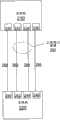
图3的示意图图示了根据本发明的一种实施例,具有虚拟端口通道综合体(complex)的链路聚集的示例。Figure 3 is a schematic diagram illustrating an example of link aggregation with a virtual port channel complex, according to one embodiment of the present invention.
图4a是系统标识符的示意图。Figure 4a is a schematic diagram of a system identifier.
图4b是端口标识符的示意图。Figure 4b is a schematic diagram of port identifiers.
图5的流程图示出了根据本发明的一种实施例,用于把来自两个网络设备的实体链路聚集以形成虚拟端口通道的技术,其中,活动链路在该虚拟端口通道综合体的这些设备间均匀地分布。Figure 5 is a flow diagram illustrating a technique for aggregating physical links from two network devices to form a virtual port channel in which active links are in the virtual port channel complex, according to one embodiment of the present invention. are evenly distributed among these devices.
图6的示意图图示了根据本发明的一种实施例,虚拟端口通道综合体与交换机之间的链路聚集以及表明活动链路的典型选择顺序的评级(ranking)。Figure 6 is a schematic diagram illustrating link aggregation between a virtual port channel complex and a switch and a ranking indicating a typical selection order of active links, according to one embodiment of the present invention.
图7的示意图图示了对于本发明的各种示例技术,虚拟端口通道综合体与个体交换机之间的链路聚集以及表明活动链路的选择顺序的评级。7 is a schematic diagram illustrating the aggregation of links between a virtual port channel complex and individual switches and rankings indicating the order of selection of active links for various example techniques of the present invention.
图8的示意图图示了根据本发明的一种实施例,虚拟端口通道综合体与个体交换机之间的链路聚集以及评级,该评级表明了在链路失效之后,对于活动链路的选择顺序的重新排序。Figure 8 is a schematic diagram illustrating the aggregation of links between a virtual port channel complex and individual switches and a ranking indicating the order in which active links are selected after a link failure, according to one embodiment of the present invention reordering of .
图9图示了适于实施本发明实施例的示例性交换机。Figure 9 illustrates an exemplary switch suitable for implementing embodiments of the present invention.
具体实施方式Detailed ways
现在将详细参考本发明的一些具体实施例,这些实施例包含了发明人所想到的用于实施本发明的最佳模式。这些具体实施例的示例被图示于附图中。尽管将结合这些具体实施例来描述本发明,但是应当明白,不应将本发明限制在所描述的实施例。相反,应当认为覆盖了可以由所附权利要求限定的本发明精神和范围内可能包含的替代、变更和等效形式。Reference will now be made in detail to specific embodiments of the invention including the best modes contemplated by the inventors for carrying out the invention. Examples of these specific embodiments are illustrated in the accompanying drawings. While the invention will be described in conjunction with these specific embodiments, it will be understood that the invention is not to be limited to the described embodiments. On the contrary, it should be considered to cover alternatives, modifications and equivalents as may be included within the spirit and scope of the invention as defined by the appended claims.
例如,将在以太网网络的背景下描述本发明的技术。但是应当注意,本发明的这些技术可以应用于其他类型的网络。在下面的说明中,阐述了大量的具体细节以提供对于本发明的详尽理解。可以不依赖于这些具体细节中的一些或全部来实施本发明。在其他情况下,公知的处理操作并未被详细描述,以免不必要地使本发明含糊不清。此外,为了清楚起见,本发明的技术和机制有时是以单数形式描述的。但是应当注意,一些实施例可以包含技术的多次重复或者机制的多个实例。例如,在许多背景下使用了“处理器”。但是应当明白,在本发明范围内,也可以使用多个处理器。For example, the techniques of the present invention will be described in the context of Ethernet networks. It should be noted, however, that the techniques of the present invention can be applied to other types of networks. In the following description, numerous specific details are set forth in order to provide a thorough understanding of the present invention. The present invention may be practiced without relying on some or all of these specific details. In other instances, well known process operations have not been described in detail so as not to unnecessarily obscure the present invention. Additionally, the techniques and mechanisms of the present invention are sometimes described in the singular for clarity. It should be noted, however, that some embodiments may contain multiple repetitions of techniques or multiple instances of mechanisms. For example, "processor" is used in many contexts. It should be understood, however, that multiple processors may also be used within the scope of the present invention.
概貌overview
根据本发明,提供了多种方法和装置来允许把来自两个或更多个网络设备的实体链路有效地聚集成一个逻辑链路(即端口通道)。通过这种聚集所形成的端口通道将在本申请中称为虚拟端口通道(“vPC”),彼此协作以形成该逻辑链路的这两个或更多个网络设备将在本申请中称为虚拟端口通道综合体(“vPC综合体”)。在具体实施例中,这两个或更多个网络设备可以以下述方式设定优先级(priority):该虚拟端口通道的活动(active)链路会自动地在vPC综合体的这些网络设备间大体上相等地分布。In accordance with the present invention, methods and apparatus are provided to allow efficient aggregation of physical links from two or more network devices into one logical link (ie, port channel). The port channel formed by this aggregation will be referred to herein as a virtual port channel ("vPC"), and the two or more network devices that cooperate with each other to form this logical link will be referred to herein as a vPC. Virtual Port Channel Complex (“vPC Complex”). In a specific embodiment, the two or more network devices can be prioritized in such a way that the active link of the virtual port channel is automatically routed between the network devices in the vPC complex roughly equally distributed.
在一种实施例中,提供了用于把两个或更多个网络设备的端口聚集成一个联合端口通道(joint port channel)或虚拟端口通道的方法,该方法包括:(i)在第一网络设备处与第二网络设备协作建立第一端口通道,所述第一端口通道形成联合端口通道的一部分,其中,所述联合端口通道把所述第一端口通道的多个链路与所述第二网络设备的第二端口通道的多个链路组合,其中,所述联合端口通道的每一链路以可通信方式与第三网络设备的端口耦合;(ii)在所述第一网络设备处,向所述第一端口通道中的每个链路指派优先级,使得一组最高优先级链路会被大体上均匀地在所述第一端口通道和所述第二端口通道之间划分;以及(iii)从所述第一网络设备向所述第三网络设备传送所述第一端口通道的每个链路的优先级。In one embodiment, a method for aggregating ports of two or more network devices into a joint port channel or virtual port channel is provided, comprising: (i) first A network device cooperating with a second network device to establish a first port channel, the first port channel forming part of a joint port channel, wherein the joint port channel connects multiple links of the first port channel with the Combining a plurality of links of a second port channel of a second network device, wherein each link of the combined port channel is communicatively coupled to a port of a third network device; (ii) on the first network at the device, assigning a priority to each link in the first port channel such that a set of highest priority links are distributed substantially evenly between the first port channel and the second port channel dividing; and (iii) communicating from the first network device to the third network device a priority for each link of the first port channel.
在具体实现方式中,所述第一网络设备与所述第二网络设备之间的协作包括对所述第一网络设备和所述第二网络设备中哪一者是主要(primary)网络设备以及所述第一网络设备和所述第二网络设备中哪一者是次要(secondary)网络设备进行识别,其中,指派所述优先级的步骤是基于所述第一网络设备被指派为主要网络设备还是次要网络设备。在某些实施例中,向所述第一端口通道中的每个链路指派优先级的步骤包括:(i)确定在建立要向所述主要网络设备的端口指派的一组优先级时所要使用的、预先建立的判据;(ii)基于所述预先建立的判据,确定这组优先级;以及(iii)向所述第一网络设备的多个端口指派这些优先级。在另一种实施例中,向所述第一端口通道中的每个链路指派优先级的步骤包括:基于所述第一网络设备被指定为主要设备还是次要设备,指派一组唯一(unique)的偶数或一组唯一的奇数。在某些实施例中,所述第一网络设备和所述第二网络设备的协作产生了虚拟端口通道综合体,所述虚拟端口通道综合体与所述第三网络设备通信以形成所述联合端口通道。在另一种实施例中,上述方法还包括:(i)至少部分地基于向所述联合端口通道的每个链路指派的这些优先级,来确定所述联合端口通道的、要被赋予活动状态的多个链路;(ii)在确定了哪些链路将是活动链路之后,在所述第一网络设备处通过对向所述第一端口通道的这些链路指派的优先级进行重新指派,来对所述第一网络设备处的这些活动链路之一的失效(failure)进行响应,使得一组最高优先级链路仍然会在所述第一端口通道和所述第二端口通道之间大体上均匀地划分;以及(iii)在对向所述第一端口通道的这些链路指派的优先级进行重新指派之后,从所述第一网络设备向所述第三网络设备传送所述第一端口通道的这些链路的重新指派的优先级。在某些实施例中,上述方法还包括:(i)至少部分地基于向所述联合端口通道的每个链路指派的这些优先级,来确定所述联合端口通道的、要被赋予活动状态的多个链路;以及(ii)在确定了哪些链路将是活动链路之后,在所述第一网络设备处通过把与所述第三网络设备进行的同步处理延迟预先定义的时间段,来对所述第二网络设备处的这些活动链路之一的失效进行响应,使得所述第二网络设备能够使用这种预先定义的时间段来对向所述第二端口通道的这些链路指派的优先级进行重新指派并把所述第二通道的这些链路这种重新指派的优先级传送给所述第三网络设备。In a specific implementation manner, the cooperation between the first network device and the second network device includes determining which of the first network device and the second network device is the primary network device and identifying which of the first network device and the second network device is a secondary network device, wherein the step of assigning the priority is based on the first network device being assigned as a primary network device The device is also a secondary network device. In some embodiments, the step of assigning a priority to each link in the first port channel includes: (i) determining what is required in establishing a set of priorities to be assigned to the ports of the primary network device; using pre-established criteria; (ii) determining the set of priorities based on said pre-established criteria; and (iii) assigning these priorities to a plurality of ports of said first network device. In another embodiment, the step of assigning a priority to each link in the first port channel includes assigning a set of unique ( unique) or a set of unique odd numbers. In some embodiments, the cooperation of the first network device and the second network device results in a virtual port channel complex that communicates with the third network device to form the joint port channel. In another embodiment, the above method further includes: (i) determining the activity to be assigned to the joint port channel based at least in part on the priorities assigned to each link of the joint port channel; (ii) after determining which links will be active links, at said first network device by reassigning priorities to those links of said first port channel assigned to respond to a failure of one of the active links at the first network device such that a set of highest priority links will still be on the first port channel and the second port channel and (iii) after reassigning the priorities assigned to the links of the first port-channel, transmitting from the first network device to the third network device the The reassignment priority of these links for the first port channel described above. In some embodiments, the method above further includes: (i) determining, based at least in part on the priorities assigned to each link of the joint port channel, the link of the joint port channel to be assigned an active status; and (ii) after determining which links will be the active links, at said first network device by delaying the synchronization process with said third network device for a predefined period of time , to respond to the failure of one of the active links at the second network device, so that the second network device can use this predefined period of time to link the links to the second port channel reassigning the assigned priorities of the links of the second path and transmitting the reassigned priorities of the links of the second path to the third network device.
在另一种实施例中,提供了一种网络设备。该网络设备是与第二网络设备进行对等通信(peer communication)的第一网络设备,所述第一网络设备包括存储器、多个端口以及处理器,所述多个端口通过第三网络设备的多个端口而耦合到所述第三网络设备,所述处理器被配置成:(i)在所述第一网络设备处与所述第二网络设备协作建立第一端口通道,所述第一端口通道形成联合端口通道的一部分,其中,所述联合端口通道把所述第一端口通道的多个链路与所述第二网络设备的第二端口通道的多个链路聚集,其中,所述联合端口通道的每一链路以可通信方式与所述第三网络设备的所述多个端口耦合;(ii)在所述第一网络设备处,向所述第一端口通道中的每个链路指派优先级,使得一组最高优先级链路会被大体上均匀地在所述第一端口通道和所述第二端口通道之间划分;以及(iii)从所述第一网络设备向所述第三网络设备传送所述第一端口通道的每个链路的优先级。In another embodiment, a network device is provided. The network device is a first network device that performs peer communication with a second network device, and the first network device includes a memory, a plurality of ports, and a processor, and the plurality of ports pass through the third network device a plurality of ports coupled to the third network device, the processor configured to: (i) establish a first port channel at the first network device in cooperation with the second network device, the first The port channel forms part of a joint port channel, wherein the joint port channel aggregates links of the first port channel with links of a second port channel of the second network device, wherein the each link of the joint port channel is communicatively coupled with the plurality of ports of the third network device; (ii) at the first network device, to each of the first port channels link assignment priorities such that a set of highest priority links is divided substantially evenly between the first port channel and the second port channel; and (iii) from the first network device The priority of each link of the first port channel is communicated to the third network device.
在另一种实施例中,本发明涉及一种以功能方式限定的装置。在某些实施例中,本发明涉及至少一种计算机可读存储介质,该介质上存储有计算机程序指令,这些计算机程序指令被布置来执行上述操作中的一项或多项。In another embodiment, the invention relates to a functionally defined device. In some embodiments, the invention relates to at least one computer-readable storage medium having stored thereon computer program instructions arranged to perform one or more of the operations described above.
在本发明的下述说明书以及附图中将更详细地呈现本发明的这些以及其他的特征和优点,附图以示例方式图示了本发明的原理。These and other features and advantages of the invention will appear in more detail in the following description of the invention and in the accompanying drawings, illustrating by way of example the principles of the invention.
具体示例性实施例Specific Exemplary Embodiments
如上所述,网络中的网络设备通常是用多个实体链路来互连的。例如,在以太网网络中,两个网络设备之间可以存在多个链路。把一对网络设备相连的这些实体链路在这些网络设备之间传输数据。As mentioned above, network devices in a network are usually interconnected by multiple physical links. For example, in an Ethernet network, multiple links can exist between two network devices. These physical links connecting a pair of network devices transmit data between the network devices.
在一些情况下,把多个实体链路聚集成一个逻辑链路可能是有利的。可以不管所用的具体实体链路而通过具体的逻辑链路来传输数据,而不是经过具体的实体链路来传输数据。已有一些机制用于把多个实体链路聚集成逻辑链路或端口通道。与这种技术有关的一种协议是IEEE 802.3ad以太网标准,一般称为链路聚集控制协议(“LACP”)。这些机制使得若干个链路或端口可以聚集成逻辑链路或端口通道。实体链路在本申请中也称为实体接口和通道,而逻辑链路在本申请中也称为逻辑接口和端口通道。In some cases, it may be advantageous to aggregate multiple physical links into one logical link. Data may be transferred over specific logical links rather than over specific physical links regardless of the specific physical link used. There are mechanisms for aggregating multiple physical links into logical links or port channels. One protocol related to this technique is the IEEE 802.3ad Ethernet standard, commonly known as the Link Aggregation Control Protocol ("LACP"). These mechanisms allow several links or ports to be aggregated into logical links or port channels. Physical links are also referred to as physical interfaces and channels in this application, and logical links are also referred to as logical interfaces and port channels in this application.
如果被聚集以形成逻辑链路的这些实体链路可以来自两个或更多个不同的网络设备,则通过这种聚集所获得的优点可以更进一步。例如,人们可能希望把来自两个或更多个网络设备的实体链路组合成一个逻辑链路。即,在一些情况下,网络设备A可能具有将其与网络设备B连接的多个实体链路。另外,这“一个”网络设备A可能还具有将其与另一网络设备C连接的多个实体链路。在一些情况下,把将网络设备A与网络设备B和C相连的实体链路中的一些或全部聚集成一个逻辑链路或端口通道可能是有利的。换言之,对于网络设备A的经聚集逻辑链路会包括来自网络设备B和C二者的实体链路。如果链路聚集除了增加链路冗余度还增加设备冗余度的话,则能够实现显著的优点。但是,用于把实体链路聚集成逻辑链路的这些传统机制没有提供用于这种聚集的手段。The advantages obtained by such aggregation can go even further if the physical links aggregated to form a logical link can come from two or more different network devices. For example, one may wish to combine physical links from two or more network devices into one logical link. That is, in some cases, network device A may have multiple physical links connecting it with network device B. In addition, this "one" network device A may also have multiple physical links connecting it with another network device C. In some cases, it may be advantageous to aggregate some or all of the physical links connecting network device A with network devices B and C into one logical link or port channel. In other words, the aggregated logical links for network device A would include physical links from both network devices B and C. Significant advantages can be realized if link aggregation increases device redundancy in addition to link redundancy. However, these conventional mechanisms for aggregating physical links into logical links do not provide a means for such aggregation.
因此,本发明的技术和机制使两个或更多个网络设备能够作为综合体或者组而一起协作,以形成联合端口通道或虚拟端口通道,该端口通道包含从构成组的这两个或更多个网络设备中的每一者到另一网络设备的链路,如下文中进一步描述的那样。通过这种聚集所形成的逻辑链路或端口通道在本申请中称为“虚拟端口通道”。此外,本发明的技术和机制提供了下述机制:这些机制用于在构成组的两个或更多个网络设备之间实现大体上相等的活动链路分布。Accordingly, the techniques and mechanisms of the present invention enable two or more network devices to work together as a complex or group to form a joint or virtual port channel that includes A link from each of the plurality of network devices to another network device, as described further below. The logical links or port-channels formed by such aggregation are referred to in this application as "virtual port-channels". Additionally, the techniques and mechanisms of the present invention provide mechanisms for achieving a substantially equal distribution of active links between two or more network devices comprising a group.
本发明的某些实施例允许有很大优点。例如,通过把可用逻辑链路的数目增多可以使逻辑链路的带宽显著增大,在多设备的背景下通过把存在的故障转移(failover)特征延伸到其他链路聚集机制中可以改善逻辑链路级的适应性,并且,逻辑拓扑结构是无环路的,因而在一些示例中不那么需要对生成树协议(Spanning Tree Protocol)的依赖性及其相关联的计算成本。Certain embodiments of the invention allow for great advantages. For example, the bandwidth of a logical link can be significantly increased by increasing the number of available logical links, and the logical link can be improved in a multi-device context by extending the existing failover feature to other link aggregation mechanisms Road-level adaptability, and the logical topology is loop-free, so in some examples the dependency on Spanning Tree Protocol (Spanning Tree Protocol) and its associated computational cost is less necessary.
此外,对属于构成组的两个或更多个网络设备的实体链路进行聚集还能够提供设备冗余度,以及随之而来的硬件失效替代路径。即,即使具体的网络设备失效或过载,数据仍然能够经过虚拟端口通道来传输。这种传输可靠性能够实现是因为当经过逻辑链路传输帧时,并不关心正在使用哪个具体的实体链路。因此,只要虚拟端口通道的这些实体链路分布在构成组的这两个或更多个网络设备上,那么即使该综合体或组的某个具体网络设备坏了,逻辑链路仍然能保持为可操作。In addition, aggregating physical links belonging to two or more network devices that make up a group can also provide device redundancy and consequently an alternate path for hardware failure. That is, even if a specific network device fails or is overloaded, data can still be transmitted through the virtual port channel. This reliability of transmission is achieved because when a frame is transmitted over a logical link, it does not care which specific physical link is being used. Therefore, even if a specific network device of the complex or group fails, the logical link remains as operable.
下面将进一步描述本发明用于在虚拟端口通道的、构成组的两个或更多个网络设备间实现大体上相等数目的活动链路的技术和机制,以及与形成虚拟端口通道有关的其他技术和机制。The techniques and mechanisms of the present invention for achieving a substantially equal number of active links between two or more network devices constituting a group of virtual port channels, as well as other techniques related to the formation of virtual port channels, will be further described below and mechanism.
图1示出了根据本发明的一种具体实现方式,为链路聚集而配置的以太网网络部分。如图所示,该网络可以包括交换机(switch)105和107,这些交换机被配置来把实体链路聚集成虚拟端口通道170。尽管只示出了两个交换机(例如105和107)对于实体链路的聚集有贡献,但是也想到了两个或更多个交换机对于具体的虚拟端口通道有贡献。另外,还应当注意,图1没有示出整个网络,而是示出了该网络的一部分。在一种实施例中,主机121和123可以被配置成服务器和/或客户端系统。Fig. 1 shows an Ethernet network part configured for link aggregation according to a specific implementation manner of the present invention. As shown, the network may include switches 105 and 107 configured to aggregate physical links into virtual port channels 170 . Although only two switches (eg, 105 and 107 ) are shown contributing to the aggregation of physical links, it is also contemplated that two or more switches can contribute to a particular virtual port channel. In addition, it should also be noted that Fig. 1 does not show the entire network, but a part of the network. In one embodiment, hosts 121 and 123 may be configured as server and/or client systems.
这些交换机中的每一者可以通过个体的实体链路,或者通过被配置成逻辑链路或端口通道的多个实体链路,而连接到相邻实体。交换机105和107也可以通过虚拟端口通道170连接到相邻的交换机109。作为虚拟端口通道综合体150的成员,交换机105和107可以协作以形成去往交换机109的虚拟端口通道170。该网络可以包括任何合适数目和类型的网络设备。在所示的实施例中,交换机105还耦合到交换机103以及交换机109。交换机107还耦合到交换机111和主机123以及交换机109。在替代性实施例(图1中未示出)中,虚拟端口通道综合体150与交换机109之间可以存在多于一个虚拟端口通道107。Each of these switches may be connected to neighboring entities by an individual physical link, or by multiple physical links configured as logical links or port channels. Switches 105 and 107 may also be connected to adjacent switch 109 through virtual port channel 170 . As members of virtual
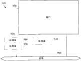
在描述更复杂的链路聚集之前,首先将描述两个网络设备之间的简单链路聚集。图2的示意图图示了根据本发明的一种实施例,两个交换机(例如图1所示的任意两个交换机)之间的链路聚集。图2所示的交换机210包括端口230、232、234和236。交换机220包括端口240、242、244和246。这些端口是实体端口,连接它们的链路是实体链路。交换机210的端口230通过个体实体链路或通道260而耦合到交换机220的端口240。相连的端口在本申请中也称为对等端口。交换机210的端口232耦合到交换机220的端口242,交换机210的端口234耦合到交换机220的端口244。所得的两个实体链路262和264可以被聚集以形成端口通道250。端口通道250在图2中被标记卫“正常端口通道”以将其与随后的附图中所示的虚拟端口通道区分开来。同样,交换机210的端口236通过实体链路266而耦合到交换机220的端口266。个体实体链路或通道260和266不被聚集。在可替代实施例中,交换机210与交换机220之间可以形成多于一个链路聚集。A simple link aggregation between two network devices will first be described before describing more complex link aggregation. FIG. 2 is a schematic diagram illustrating link aggregation between two switches (for example, any two switches shown in FIG. 1 ) according to an embodiment of the present invention. Switch 210 shown in FIG. 2 includes
图3的示意图图示了根据本发明的一种实施例,具有虚拟端口通道综合体340的链路聚集的示例。大体上,本发明的示例技术把来自两个(或更多个)网络设备的多个链路聚集以形成去往另一网络设备的逻辑链路或端口通道。如图3所示,虚拟端口通道综合体(“vPC综合体”)340包括交换机1(Switch_1)310和交换机2(Switch_2)320。Switch_1 310和Switch_2 320可以彼此协作以形成去往另一交换机3(Switch_3)330的虚拟端口通道300。Figure 3 is a schematic diagram illustrating an example of link aggregation with a virtual port channel complex 340, according to one embodiment of the present invention. In general, the example techniques of this disclosure aggregate multiple links from two (or more) network devices to form a logical link or port channel to another network device. As shown in FIG. 3 , virtual port channel complex ("vPC complex") 340 includes Switch 1 (Switch_1 ) 310 and Switch 2 (Switch_2 ) 320 .
尽管未图示图3中这些交换机的端口,但它们在实体链路380、382、384、386、390、392、394和396的各个末端以与图2所示方式相同的方式存在于Switch_1、Switch_2和Switch_3中。在这种示例中,vPC综合体340包括八个端口:四个在Switch_1处,四个在Switch_2处。在所示的这种示例中,Switch_3包括八个端口。Switch_1和Switch_2的个体端口通过个体实体链路或通道而连接到Switch_3的个体端口。Although the ports of these switches in FIG. 3 are not shown, they exist on Switch_1, Switch_2 and Switch_3. In this example, vPC complex 340 includes eight ports: four at Switch_1 and four at Switch_2. In such an example shown, Switch_3 includes eight ports. Individual ports of Switch_1 and Switch_2 are connected to individual ports of Switch_3 through individual physical links or channels.
在一种构造中,图3所示的vPC综合体可以通过四个实体链路384、386、390和392而连接到Switch_3。从Switch_1发出的实体链路384和386可以被配置成第一端口通道365。从Switch_2发出的实体链路390和392可以被配置成第二端口通道375。第一端口通道365和第二端口通道375可以被配置以形成虚拟端口通道300。即,在具体实施例中,来自Switch_1和Switch_2的多个链路可以首先被配置成第一端口通道365和第二端口通道375,然后被配置成虚拟端口通道300。在替代性实施例中,实体链路384、386、390、392可以被配置成虚拟端口通道300而无需事先被配置成第一端口通道365和第二端口通道375。In one configuration, the vPC complex shown in FIG. 3 may be connected to Switch_3 by four
虚拟端口通道综合体可以同时通过虚拟端口通道和正常端口通道而连接到另一设备。如图所示,Switch_1也可以通过正常端口通道360连接到Switch_3。同样,Switch_2可以通过正常端口通道370连接到Switch_3。端口通道360和370被描述为正常的,是因为它们可以用其他链路聚集技术(包括常规的链路聚集技术)来形成。在未示出的替代性实施例中,任何成对的交换机也可以通过个体实体链路而彼此连接。A virtual port channel complex can be connected to another device through both a virtual port channel and a normal port channel. As shown, Switch_1 can also be connected to Switch_3 through normal port channel 360. Likewise, Switch_2 can connect to Switch_3 through normal port channel 370. Port channels 360 and 370 are described as normal because they can be formed using other link aggregation techniques, including conventional link aggregation techniques. In an alternative embodiment not shown, any pair of switches may also be connected to each other by individual physical links.
尽管Switch_1和Switch_2可以协作以形成虚拟端口通道,但它们在其他方面可以在很大程度上独立地操作。在具体实施例中,Switch_1和Switch_2具有分布式控制平面(control plane)、分布式数据平面(dataplane)和分布式管理。这种分布式的性质可以提供实现形式简便和可升级性(scalability)的优点。Although Switch_1 and Switch_2 can cooperate to form a virtual port channel, they can otherwise operate largely independently. In a specific embodiment, Switch_1 and Switch_2 have a distributed control plane (control plane), a distributed data plane (dataplane) and distributed management. This distributed nature can provide the advantages of simplicity of implementation and scalability.
对等链路300是把第一本地交换机310与第二本地交换机320相连的交换机间链路(interswitch link,“ISL”)。对等链路350可以用来在Switch_1与Switch_2的控制平面之间传送信息,以执行vPC综合体的任何合适的对等功能。在具体实施例中,除了其他通信,对等链路350还可以执行Switch_1与Switch_2之间的心跳(heartbeat)机制,该机制传送与虚拟端口通道的这些链路有关的状态信息。在替代性实施例中,由对等链路350传输的信息是通过其他机制(例如以无线方式或者通过其他设备间接地)传输的,对等链路350不是必需的。Peer link 300 is an interswitch link ("ISL") connecting a first
在一些示例中,作为建立虚拟端口通道的处理的一部分,网络设备或交换机可以交换协议数据单元(“PDU”)。这些PDU和用于传送与协议有关的数据的其他类似分组在本申请中称为链路聚集协议分组。链路聚集协议分组可以传送建立兼容性(compability)所需的数据以及建立虚拟端口通道300所需的参数。在一种示例中,它们提供了链路广告(linkadvertisement)和优先级消息。它们可以在vPC综合体(例如340)的交换机或设备与另一交换机(例如Switch_3)之间的各个实体链路的伙伴实体端口之间发送。In some examples, network devices or switches may exchange protocol data units ("PDUs") as part of the process of establishing a virtual port channel. These PDUs and other similar packets used to convey protocol-related data are referred to in this application as Link Aggregation Protocol packets. Link Aggregation Protocol packets may convey data required to establish compatibility and parameters required to establish
链路聚集协议分组因而可以包括诸如下述参数:系统标识符、端口标识符、端口通道标识符、沟通(channeling)意图、沟通状态。沟通意图参数可以向对等端口表明该端口是否意图参与端口通道,或以其他方式作为个体端口。沟通状态参数可以把发送端口的当前沟通状态向对等端口通知。该参数由这些经过附接的对等端口来交换,以在对链路的沟通状态达成协议并确保这两端是同步的。Link aggregation protocol packets may thus include parameters such as: system identifier, port identifier, port channel identifier, channeling intent, communication status. A communication intent parameter may indicate to a peer port whether the port intends to participate in a port channel, or otherwise act as an individual port. The communication state parameter may inform the peer port of the current communication state of the sending port. This parameter is exchanged by the attached peer ports to agree on the communication state of the link and to ensure that the two ends are synchronized.
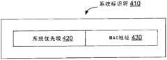
各个网络设备或交换机可以被配置有具体的系统标识和系统优先级。例如,如图4a所示,各个设备可以与系统标识符410相关联,该标识符由系统优先级420和MAC地址430串接组成。如图4a所示,在一些实施例中,系统标识符410是全局唯一标识符,例如与全局媒体接入控制(MAC)地址430串接的交换机优先级编号420。Each network device or switch can be configured with specific system identification and system priority. For example, as shown in FIG. 4 a , each device may be associated with a system identifier 410 consisting of a system priority 420 and a MAC address 430 concatenated. As shown in FIG. 4 a , in some embodiments, the system identifier 410 is a globally unique identifier, such as a switch priority number 420 concatenated with a global medium access control (MAC) address 430 .
每个端口还可以与端口标识符相关联。图4b是端口标识符440的示意图。如图所示,在一些实施例中,端口标识符440可以采取端口指定标识符的形式,例如与端口编号460串接的端口优先级450。端口编号本身可以是与个体端口编号470串接的插槽(slot)(或线路卡(line card))编号460。端口优先级450可以从一个范围的值中选取,也可以具有给定的缺省值。端口优先级450可以是可由用户配置的,并可以由系统管理员设定。在一种实现方式中,端口优先级450可以包括端口标识符440的数值高位数字。Each port can also be associated with a port identifier. FIG. 4 b is a schematic diagram of a port identifier 440 . As shown, in some embodiments, port identifier 440 may take the form of a port designation identifier, such as port priority 450 concatenated with port number 460 . The port number itself may be a slot (or line card) number 460 concatenated with an
每个端口通道也可以与标识符相关联或被配置有标识符。在一些示例中,每个端口通道具有针对该通道各个端口的端口通道标识符。根据各种实施例,每个端口通道标识符是网络设备或交换机内的唯一编号。Each port channel may also be associated with or configured with an identifier. In some examples, each port channel has a port channel identifier for each port of the channel. According to various embodiments, each port channel identifier is a unique number within a network device or switch.
在具体实施例中,可以基于哪些链路具有的与之相关联的端口标识符440最低,来针对活动状态选择链路。这样,向端口标识符440指派值可以确定针对活动状态来对端口进行选择的顺序。在具体实施例中,端口标识符可以用来便于针对活动状态自动地选择链路。这种自动选择可以包括向端口标识符440的端口优先级450指派值,如下文中更详细地描述的那样。In particular embodiments, links may be selected for active status based on which links have the lowest port identifier 440 associated with them. As such, assigning a value to port identifier 440 may determine the order in which ports are selected for the active state. In particular embodiments, port identifiers may be used to facilitate automatic selection of links for active states. Such automatic selection may include assigning a value to port priority 450 of port identifier 440, as described in more detail below.
在具体实施例中,本发明的技术和机制使用系统标识符410来把虚拟端口通道综合体340呈现为单一的网络设备,以与另一网络设备建立逻辑链路。例如,在交换上文所述的PDU以建立逻辑链路时,虚拟端口通道综合体可能希望将其自身呈现为单一实体而不是呈现为其要素(constituent)网络设备。在一些实施例中,这种结果是通过向虚拟端口通道综合体指派新的系统标识符(例如410)并使用这个新的系统标识符将其自身呈现给另一网络设备(例如Switch_3 330)来实现的。具体而言,不是向另一网络设备传送其要素网络设备各自的系统标识符,而是虚拟端口通道综合体能够呈现新的系统标识符,该新的系统标识符包括新的MAC地址和/或新的系统优先级。这些要素网络设备协作来向该另一网络设备传送虚拟端口通道综合体的系统标识符410。In particular embodiments, the techniques and mechanisms of the present invention use system identifier 410 to present virtual port channel complex 340 as a single network device to establish a logical link with another network device. For example, when exchanging the PDUs described above to establish a logical link, the virtual port channel complex may wish to present itself as a single entity rather than as its constituent network device. In some embodiments, this result is achieved by assigning a new system identifier (e.g., 410) to the virtual port channel complex and presenting itself to another network device (e.g., Switch_3 330) using this new system identifier. Achieved. Specifically, rather than communicating the respective system identifiers of its constituent network devices to another network device, the virtual port channel complex can assume a new system identifier that includes a new MAC address and/or New system priority. The element network devices cooperate to communicate the system identifier 410 of the virtual port channel complex to the other network device.
在具体实施例中,虚拟端口通道是部分地通过经现有的协议标准(例如链路聚集控制协议(“LACP”)、IEEE 802.3ad)进行操作来形成的。在具体实施例中,本发明的技术和机制通过建立在这些现有的链路聚集技术纸上而实现了实现形式相对简便和可升级性。把vPC综合体的这些设备呈现为单一的实体还可以使本发明的技术能够结合针对链路聚集的传统机制(例如LACP)来使用。In particular embodiments, virtual port channels are formed in part by operating via existing protocol standards (eg, Link Aggregation Control Protocol ("LACP"), IEEE 802.3ad). In a specific embodiment, the technology and mechanism of the present invention are based on these existing link aggregation technologies to achieve relatively simple implementation and upgradeability. Presenting these devices of the vPC complex as a single entity also enables the techniques of the present invention to be used in conjunction with traditional mechanisms for link aggregation, such as LACP.
端口优先级可以是可人工配置的,但是这种人工处理是麻烦、耗时且容易出错的。如下文所述,本发明的技术和机制提供了自动地配置虚拟端口通道300的端口优先级的方式。Port priority may be manually configurable, but such manual processing is cumbersome, time-consuming, and error-prone. As described below, the techniques and mechanisms of the present invention provide a way to automatically configure the port priorities of
图5的流程图示出了根据本发明的一种实施例,用于聚集两个网络设备的技术。该流程示出了一种实施例,用于形成虚拟端口通道,并向该虚拟端口通道综合体的端口指派优先级以在该虚拟端口通道综合体的这些联合网络设备间实现大体上相等的活动链路数目。在图5所示处理的第一个步骤510,两个网络设备被配置以形成去往被连网络设备(在图5中称为第三网络设备)的虚拟端口通道。这两个网络设备可以组成vPC综合体。该第一步骤510可以包括确定vPC综合体的公共的系统标识符。它还可以包括在这两个联合网络设备处都许用(enable)vPC特征,并建立vPC对等链路。另外,第一步骤510还可以包括在这两个联合网络设备之间交换消息。第一步骤510还可以包括由这两个联合网络设备向被连网络设备提供它们交换机配置的拷贝,以确定这些vPC综合体网络设备与被连网络设备之间是否有在开始虚拟端口通道之前需要解决的任何配置不一致。第一步骤510还可以包括解决任何一致性问题并确保任何所需的协议都是和谐的。Figure 5 is a flowchart illustrating a technique for aggregating two network devices, according to one embodiment of the present invention. This flow shows an embodiment for forming virtual port channels and assigning priorities to ports of the virtual port channel complex to achieve substantially equal activity among the federated network devices of the virtual port channel complex number of links. In a
在图5所示处理的第二个步骤520,这两个联合网络设备可以协作以确定该虚拟端口通道中多个链路的优先级,使得活动链路大体上均匀地在这两个联合网络设备之间划分。这个第二步骤520可以包括识别这两个联合网络设备中哪一者是主要系统、哪一者是次要系统,并确定预先建立的判据,这个判据将在建立向主要网络设备和次要网络设备的端口指派的一组优先级时使用。这个第二步骤520还可以包括基于这个预先建立的判据来确定这组优先级,并向第一和第二网络设备的多个端口指派这组优先级。In a
在图5所示处理的第三个步骤530,这两个联合网络设备可以向被连的网络设备通知所确定的链路的优先级。在具体实施例中,这种通信可以通过下述方式来执行:向端口标识符指派与被确定的优先级相对应的优先级值,并在由vPC综合体向被连网络设备(例如图3的Switch_3)发送的链路聚集协议分组中包含相应的端口标识符和公共的系统标识符。In a
在图5所示处理的第四个步骤540,这两个联合网络设备和被连网络设备可以把该虚拟端口通道用于数据通信。In the
图6的示意图图示了根据本发明的一种实施例,虚拟端口通道综合体340的Switch_1和Switch_2与Switch_3之间的链路聚集以及表明活动链路的典型选择情况的优先级评级。对于以太网网络中所用的LACP协议,例如如果端口1/1-8(插槽1的端口1-8)被配置在端口通道中,则对于活动状态,端口1/1-8将比端口2/1-8(插槽2的端口1-8)优先。根据LACP的规约,具有较低的端口标识符440的端口首先被选择来集束(bundling)。FIG. 6 is a schematic diagram illustrating link aggregation between Switch_1 and Switch_2 and Switch_3 of virtual port channel complex 340 and priority ratings indicating a typical selection of active links according to one embodiment of the present invention. For the LACP protocol used in Ethernet networks, for example, if
尽管在单一机架(chassis)的背景下有些顾虑,但是在例如构成组的两个网络设备作为vPC综合体而协作的背景下,这种评级结果更容易出问题。例如,在没有不同的端口标识符450配置的情况下,来自活动机架的端口可以一直比来自待机(standby)网络设备的端口优先地用作活动链路。这种配置难以利用由形成下述端口通道所赋予的设备冗余度优势:该端口通道包括在vPC综合体的两个(或更多个)联合网络设备之间均匀分布的实体链路。While somewhat worrisome in the context of a single chassis, such ratings are more problematic in the context of, for example, two network devices forming a group collaborating as a vPC complex. For example, without a different port identifier 450 configuration, a port from an active chassis may always be used as an active link in preference to a port from a standby network device. This configuration makes it difficult to take advantage of the device redundancy advantages conferred by forming a port channel comprising physical links evenly distributed between two (or more) federated network devices of a vPC complex.
可以利用对端口优先级的智能指派来推翻通常的评级顺序。在具体实施例中,端口优先级的交错(interleaving)可以解决上述问题。可以容易地意识到,对于以使用端口标识符来反映所需评级顺序的方式来指派端口优先级,存在多种可能性。The usual ranking order can be overridden with intelligent assignment of port priorities. In a specific embodiment, the interleaving of port priorities can solve the above problems. It can be readily appreciated that there are several possibilities for assigning port priorities in such a way that port identifiers are used to reflect the desired ranking order.
图6示出了在不使用本发明的机制和技术的情况下操作的虚拟端口通道系统的操作。为了说明目的,在图6中,所示的系统是活动链路的最大数目是两个、并且待机链路的最大数目是两个的系统(尽管通常会利用更多的活动链路)。虚拟端口通道300包含四个实体链路。链路610被标记为S1L1以表明Switch_1 310的第一链路;链路620被标记为S1L2以表明Switch_1 310的第二链路,等等。假定不应用本发明的技术和机制,则由于上述原因,则将得到由带圈的数字所表示的数字(1)到(4)表明的评级顺序。即,链路S1L1将被评级为第一,链路S1L2将被评级为第二。链路S2L1将被评级为第三,而链路S2L2将被评级为第四。通过这样的评级,假定活动链路的最大数目是两个,并且待机链路的最大数目是两个,则链路S1L1和S1L2将被标记为活动链路。换言之,全部这些活动链路会来自一个网络设备。Figure 6 illustrates the operation of a virtual port channel system operating without using the mechanisms and techniques of the present invention. For purposes of illustration, in FIG. 6, the system shown is one with a maximum number of active links of two and a maximum number of standby links of two (although more active links would typically be utilized).
图7的示意图图示了根据本发明的一种实施例,个体交换机与虚拟端口通道综合体之间的链路聚集以及反映虚拟端口通道的活动链路的选择方式的优先级评级。对于这种评级,所选择的活动链路会大体上均匀地在vPC综合体的这些交换机之间分布。假定应用本发明的技术和机制,则将得到由带圈的数字所表示的评级顺序(1)到(4)。Switch_1的链路S1L1将被评级为第一(1),而Switch_1的链路S1L2将仅被评级为第三(3)。Switch_2的链路S2L1将被评级为第二(2),而Switch_2的链路S2L2将被评级为第四(4)。通过这种评级,假定活动链路的最大数目是两个,并且待机链路的最大数目是两个,则由粗线包围的链路——即链路S1L1和S2L1——将被标记为活动链路。Figure 7 is a schematic diagram illustrating link aggregation between individual switches and a virtual port channel complex and priority ratings reflecting how active links of a virtual port channel are selected, according to one embodiment of the present invention. For this rating, the selected active links would be substantially evenly distributed among the switches of the vPC complex. Assuming the techniques and mechanisms of the present invention are applied, the ranking order (1) to (4) represented by the encircled numbers will result. Link S1 L1 of Switch_1 will be rated first (1), while link S1 L2 of Switch_1 will only be rated third (3). Link S2 L1 of Switch_2 will be rated second (2), while link S2 L2 of Switch_2 will be rated fourth (4). With this rating, assuming that the maximum number of active links is two and the maximum number of standby links is two, the links surrounded by thick lines—that is, links S1 L1 and S2 L1 — — will be marked as an active link.
对于vPC综合体的端口优先级的指派可以通过多种机制来实现。在一种示例中,这些要素网络设备可能首先需要在它们自身之间确定哪个网络设备是主要系统,哪个网络设备是次要系统。这种确定可以基于预先建立的判据(例如谁具有最低的设备MAC地址430和设备系统标识符410)来自动地作出。一旦确定了主要系统和次要系统,网络设备就可以查询预先建立的一组端口优先级,并基于它是主要系统还是次要系统来选取一组端口优先级。确定了可应用的这组端口优先级,然后就可以前进到从它的端口优先级组向它的vPC端口中的每一者指派个体端口优先级。可以以使每个端口将具有唯一的端口优先级的方式来指派端口优先级。Assignment of port priorities for the vPC complex can be implemented through various mechanisms. In one example, these element network devices may first need to determine among themselves which network device is the primary system and which network device is the secondary system. This determination can be made automatically based on pre-established criteria such as who has the lowest device MAC address 430 and device system identifier 410 . Once the primary and secondary systems are determined, the network device can query a pre-established set of port priorities and choose a set of port priorities based on whether it is the primary or secondary system. Having determined the applicable set of port priorities, it can then proceed to assigning an individual port priority to each of its vPC ports from its port priority set. Port priorities can be assigned in such a way that each port will have a unique port priority.
在具体实施例中,这些vPC综合体设备随后可以通过链路聚集协议分组来向其伙伴网络设备(即虚拟端口通道的另一端的被连设备)广告其个体vPC端口各自的优先级。该信息可以通过链路聚集协议分组来发送。一旦接收到这些链路聚集协议分组,该伙伴网络设备就可以向接收到链路聚集协议分组的实体端口指派与其配对vPC综合体端口的端口优先级相同的端口优先级。例如,第一网络设备可以对于插槽1/端口1通告优先级“一”。这个同一端口优先级随后可以被指派给该伙伴网络设备的相应端口。In particular embodiments, these vPC complex devices may then advertise the respective priorities of their individual vPC ports to their partner network devices (ie, connected devices at the other end of the virtual port channel) via Link Aggregation Protocol packets. This information may be sent via Link Aggregation Protocol packets. Upon receiving these link aggregation protocol packets, the partner network device may assign the port priority of the entity port that received the link aggregation protocol packets to be the same as the port priority of its counterpart vPC complex port. For example, the first network device may advertise a priority of "one" for
在具体实施例中,端口优先级信息随后可以由伙伴网络设备用来对于活动状态选择链路。在具体实施例中,这种选择可以根据用于确定活动链路的已有技术(例如LACP中那些)来进行。在LACP下,如果一些链路具有在数值上较低的端口标识符,则它们被选择以集束成活动链路。即,具有最低的端口标识符的端口首先被选择,然后具有第二低的端口标识符的端口被选择,等等。In particular embodiments, the port priority information may then be used by a partner network device to select a link for an active state. In particular embodiments, this selection may be made according to existing techniques for determining active links, such as those in LACP. Under LACP, some links are selected to bundle into active links if they have numerically lower port identifiers. That is, the port with the lowest port identifier is selected first, then the port with the second lowest port identifier is selected, and so on.
假定由两个网络设备组成的虚拟端口通道综合体,在具体实施例中,实现了一种系统,在该系统中,第一网络设备(例如主要设备)的端口被指派奇数(即1、3、5、7等),第二网络设备(例如次要设备)的端口被指派偶数(即2、4、6、8等)。随后,利用LACP提供的特征,可以实现该vPC综合体的这些成员网络设备之间大致相等的活动链路分布。具体实施例把LACP的这些自动选择特征与上述端口优先级指派特征相组合来实现活动链路的均匀分布。Assuming a virtual port channel complex consisting of two network devices, in a specific embodiment a system is implemented in which the ports of the first network device (e.g. the master) are assigned odd numbers (i.e. 1, 3 , 5, 7, etc.), the ports of the second network device (eg, the secondary device) are assigned even numbers (ie, 2, 4, 6, 8, etc.). Then, using the features provided by LACP, an approximately equal distribution of active links among the member network devices of the vPC complex can be achieved. Particular embodiments combine these automatic selection features of LACP with the port priority assignment features described above to achieve an even distribution of active links.
换言之,vPC综合体的端口优先级可以以下述方式来指派:该方式使得Switch_1的端口在优先级方面与Switch_2的端口交错。例如,在一种实施例中,LACP端口优先级被配置如下:In other words, the port priorities of the vPC complex can be assigned in such a way that the ports of Switch_1 are interleaved with the ports of Switch_2 in priority. For example, in one embodiment, LACP port priority is configured as follows:
1/1的优先级=1,2/1的优先级=21/1 priority = 1, 2/1 priority = 2
1/2的优先级=3,2/2的优先级=41/2 priority = 3, 2/2 priority = 4
1/3的优先级=5,2/3的优先级=61/3 priority = 5, 2/3 priority = 6
… …... ...
1/7的优先级=13,2/7的优先级=141/7 priority = 13, 2/7 priority = 14
1/8的优先级=15,2/8的优先级=161/8 priority = 15, 2/8 priority = 16
通过这种区分优先级方式,端口1/1-4和2/1-4将被集束,端口1/5-8和2/5-8将待机。图7示出了在总共只有四个链路(活动链路的最大数目是两个,并且待机链路的最大数目是两个)的系统中,这种区分优先级方案如何工作的一种示例。具有由粗线包围的优先级数字的链路(链路S1L1和S2L1)将被标记为活动链路,从而实现对于在两个或更多个网络设备间对于大体上相等数目的活动链路的追求。With this prioritization,
图8的示意图图示了根据本发明的一种具体实现方式,个体交换机与虚拟端口通道综合体之间的链路聚集,以及在虚拟端口通道的这些实体链路之一坏了的时候由本发明的技术所产生的经调整的评级顺序。例如,本发明的技术和机制不应限于初始链路选择。在链路失效的情况下,具体实施例可以提供对于包含失效链路的vPC网络设备的端口优先级进行重新指派的机制,以在vPC综合体的这些网络设备间维持大体上均匀的活动链路分布。Figure 8 is a schematic diagram illustrating link aggregation between an individual switch and a virtual port-channel complex, and when one of these physical links of a virtual port-channel fails, according to a specific implementation of the present invention. The adjusted ranking order produced by the technology. For example, the techniques and mechanisms of the present invention should not be limited to initial link selection. In the event of a link failure, particular embodiments may provide mechanisms for reassigning port priorities of vPC network devices containing failed links to maintain a substantially even distribution of active links across those network devices in the vPC complex distributed.
在具体实施例中,如果某个链路坏了,网络设备可以从失效的该链路取得端口优先级并将这个优先级指派给其链路的另一者。例如,在图8所示的示例中,当Switch_2的活动链路S2L1(该链路具有优先级(2))失效时,这个Switch_2可以对其vPC端口的优先级进行重新指派,使得此前具有优先级(4)的链路现在会具有优先级(2)。这种重新指派处理可以包括与最初向这些vPC端口指派端口优先级时所用的处理相似的处理。In a specific embodiment, if a certain link fails, the network device can take the port priority from the failed link and assign this priority to the other of its links. For example, in the example shown in Figure 8, when the active link S2 L1 of Switch_2 (the link has priority (2)) fails, this Switch_2 can reassign the priority of its vPC port, so that Links that previously had priority (4) will now have priority (2). This reassignment process may include similar processing as was used when initially assigning port priorities to these vPC ports.
另外,也可以给vPC综合体340的、并未经历失效链路的交换机(例如Switch_1)提供机制,使同步处理延迟某个预先建立的时间段,以确保Switch_2的链路有足够的时间来完成上述重新指派端口优先级的处理。In addition, it is also possible to provide a mechanism for the switch (such as Switch_1) of the vPC complex 340 that has not experienced a failed link to delay the synchronization process for a certain pre-established period of time to ensure that the link of Switch_2 has enough time to complete The above process of reassigning port priority.
如图8所示,Switch_3可以通过向Switch_1发送消息,来对S2L1的链路失效进行响应,使具有优先级(3)的链路S1L2成为活动链路。Switch_1可以进行检查以得知Switch_2是否已有链路坏了(例如通过对等通信)。如果Switch_1确定Switch_2有链路失效,则Switch_1可以随后引入预先建立的时间长度的延迟,以给Switch_2时间来对其端口指派进行重新配置。在这个预先建立的时间长度的延迟之后,Switch_1可以对Switch_3的、使链路S1L2活动的请求作出否定响应。Switch_3随后可以再次履行其选择处理,这次可以选择链路S2L2,该链路在Switch_2对其优先级指派进行重新配置之后具有优先级(2)。这个新的优先级将使由粗线包围的链路(即链路S1L1和S2L2)现在被标记为活动链路。这种配置会在vPC综合体的这两个网络设备间实现大体上均匀的活动链路数目。As shown in FIG. 8 , Switch_3 can respond to the link failure of S2 L1 by sending a message to Switch_1 , so that the link S1 L2 with priority (3) becomes an active link. Switch_1 can check to know whether Switch_2 has a broken link (for example, through peer-to-peer communication). If Switch_1 determines that Switch_2 has a link failure, Switch_1 may then introduce a delay of a pre-established length of time to give Switch_2 time to reconfigure its port assignments. After a delay of this pre-established length of time, Switch_1 may respond negatively to Switch_3's request to make link S1 L2 active. Switch_3 can then perform its selection process again, this time selecting link S2 L2 , which has priority (2) after Switch_2 has reconfigured its priority assignments. This new priority will cause the links surrounded by thick lines (ie links S1 L1 and S2 L2 ) to be marked as active links now. Such a configuration would achieve a substantially even number of active links between the two network devices of the vPC complex.
如上所述,用于对端口进行聚集的技术可以在多种网络设备或交换机中执行。根据各种实施例,交换机包括处理器、网络接口和存储器。如本领域技术人员所知,也可以提供各种端口、媒体接入控制(MAC)块和缓冲器。另外,尽管描述了示例性的交换机,但是上述这些实施例可以在多种网络设备(例如服务器)中以及用多种介质来实现。As described above, techniques for aggregating ports can be implemented in a variety of network devices or switches. According to various embodiments, a switch includes a processor, a network interface and memory. Various ports, media access control (MAC) blocks and buffers may also be provided as known to those skilled in the art. Additionally, while an exemplary switch is described, the above-described embodiments may be implemented in a variety of network devices (eg, servers) and in a variety of media.
现在参考图9,适于实现本发明实施例的交换机310包括主中央处理单元(CPU)910、接口950和总线960(例如PCI总线)。当在合适的软件或固件控制下动作时,CPU 910负责诸如对计算和网络管理进行交换和/或路由(routing)的任务。它优选为在软件的控制下完成所有这些功能,该软件包括操作系统(例如Cisco Systems,Inc.的Internetwork OperatingSystem(IOS
接口950通常是作为接口卡(有时候称为“线路卡”)来提供的。它们一般对分组或分组段(packet segment)通过网络的发送和接收进行控制,有时候支持与交换机310一起使用的其他外围设备。可以提供的接口包括以太网接口、帧中继接口、线缆接口、DSL接口、令牌环接口等。另外,也可以提供各种非常高速的接口,例如快速以太网接口、吉比特(Gigabit)以太网接口、ATM接口、HSSI接口、POS接口、FIID接口等。这些接口一般可以包括适于与合适的介质进行通信的端口。在一些情形下,它们还可以包括独立的处理器,在一些情况下可以包括易失性的RAM。这些独立的处理器可以对通信密集(communications intensive)的任务进行控制,这些任务例如分组交换和/或路由、媒体控制和广告。通过给这些通信密集的任务提供单独的处理器,这些接口使主微处理器910可以有效地执行交换和/或路由计算、网络诊断、安全功能等。
尽管图9所示的系统是本发明的一种具体交换机,但它决不是可以实现本发明的仅有交换机架构。例如,常常使用这样的架构:该架构具有对通信进行处理的单一处理器,并对计算进行交换和/或路由。此外,也可以把其他类型的接口和介质与该交换机一起使用。Although the system shown in FIG. 9 is a specific switch of the present invention, it is by no means the only switch architecture on which the present invention can be implemented. For example, architectures are often used that have a single processor that handles communications and switches and/or routes computations. Additionally, other types of interfaces and media can be used with the switch.
不管网络设备的配置如何,它都可以采用一个或多个存储器或存储器模块(例如存储器块940),该存储器或存储器模块被配置来存储数据、用于通用网络操作的程序指令、和/或本申请中所述的发明技术。这些程序指令可以对操作系统和/或一个或多个应用的操作进行控制。这一个或多个存储器还可以被配置来存储合理份额的值和参数、突发阈值、最小和最大阈值、选项选择位、类参数/说明、定时器、队列特性、分组到达历史参数等。Regardless of the configuration of a network device, it may employ one or more memories or memory modules (such as memory block 940) configured to store data, program instructions for general network operations, and/or Inventive technology described in the application. These program instructions may control the operation of the operating system and/or one or more applications. The one or more memories may also be configured to store a fair share of values and parameters, burst thresholds, minimum and maximum thresholds, option selection bits, class parameters/descriptions, timers, queue characteristics, packet arrival history parameters, and the like.
由于这些信息和程序指令可以被用来实现本申请中所述的系统/方法,所以本发明涉及机器可读介质,该介质包含程序指令、状态信息等以执行本申请中所述的各种操作。机器可读介质的示例包括但不限于:磁性介质(例如硬盘、软盘和磁带);光学介质(例如CD-ROM盘和DVD);磁光介质(例如可光读的软磁盘(floptical disk));被专门配置来存储和执行程序指令的硬件器件(例如只读存储器器件(ROM)和随机存取存储器(RAM))。本发明也可以以经过合适介质(例如无线电波、光学线路、电线等)而行进的载波的形式来实施。这些程序指令的示例既包括机器代码(例如由编译器产生的机器代码),也包括包含高级代码的文件,所述高级代码可以用解释器来由计算机执行。Since such information and program instructions can be used to implement the systems/methods described in this application, the present invention relates to machine-readable media containing program instructions, state information, etc. to perform the various operations described in this application . Examples of machine-readable media include, but are not limited to: magnetic media (such as hard disks, floppy disks, and magnetic tape); optical media (such as CD-ROM disks and DVDs); magneto-optical media (such as optically readable floptical disks); Hardware devices (such as read-only memory devices (ROM) and random-access memory (RAM)) that are specially configured to store and execute program instructions. The invention can also be implemented in the form of carrier waves traveling through a suitable medium (eg, radio waves, optical lines, electrical wires, etc.). Examples of these program instructions include both machine code, such as produced by a compiler, and files containing high-level code that can be executed by a computer using an interpreter.
尽管已经参考本发明的具体实施例具体图示和描述了本发明,但是本领域技术人员应当理解,在不脱离本发明的精神和范围的情况下,可以对所公开的实施例的形式和细节进行改变。例如,本发明的实施例可以通过各种网络协议和架构来使用。因此,本发明应当被解释为包含了落在本发明真实精神和范围内的全部变更和等同形式。Although the invention has been particularly shown and described with reference to specific embodiments thereof, it will be understood by those skilled in the art that changes may be made in form and detail of the disclosed embodiments without departing from the spirit and scope of the invention. Make changes. For example, embodiments of the invention may be used with various network protocols and architectures. Therefore, the present invention should be interpreted as including all changes and equivalents falling within the true spirit and scope of the present invention.
Claims (20)
Applications Claiming Priority (3)
| Application Number | Priority Date | Filing Date | Title |
|---|---|---|---|
| US12/467,675US8401026B2 (en) | 2009-05-18 | 2009-05-18 | Achieving about an equal number of active links across chassis in a virtual port-channel environment |
| US12/467,675 | 2009-05-18 | ||
| PCT/US2010/035287WO2010135345A1 (en) | 2009-05-18 | 2010-05-18 | Achieving about an equal number of active links across chassis in a virtual port-channel environment |
Publications (2)
| Publication Number | Publication Date |
|---|---|
| CN102428679Atrue CN102428679A (en) | 2012-04-25 |
| CN102428679B CN102428679B (en) | 2015-01-07 |
Family
ID=43068465
Family Applications (1)
| Application Number | Title | Priority Date | Filing Date |
|---|---|---|---|
| CN201080021772.3AExpired - Fee RelatedCN102428679B (en) | 2009-05-18 | 2010-05-18 | Achieving about an equal number of active links across chassis in a virtual port-channel environment |
Country Status (4)
| Country | Link |
|---|---|
| US (1) | US8401026B2 (en) |
| EP (1) | EP2433395B1 (en) |
| CN (1) | CN102428679B (en) |
| WO (1) | WO2010135345A1 (en) |
Cited By (8)
| Publication number | Priority date | Publication date | Assignee | Title |
|---|---|---|---|---|
| CN103580979A (en)* | 2012-07-24 | 2014-02-12 | 中兴通讯股份有限公司 | Logic channel establishing method and system, edge virtual bridging station and bridges |
| WO2014056367A1 (en)* | 2012-10-12 | 2014-04-17 | 中兴通讯股份有限公司 | Aggregation port id allocation method and device |
| CN104488238A (en)* | 2012-07-23 | 2015-04-01 | 思科技术公司 | System and method for cluster link aggregation control in a network environment |
| CN107078951A (en)* | 2014-11-21 | 2017-08-18 | 思科技术公司 | Recovery from Virtual Port Channel Peer Failure |
| CN107347027A (en)* | 2017-06-08 | 2017-11-14 | 中国电子信息产业集团有限公司第六研究所 | A kind of link redundancy communication system based on EtherCAT |
| CN109716717A (en)* | 2016-09-07 | 2019-05-03 | 思科技术公司 | From software-defined network controller management virtual port channel switching equipment peer-to-peer |
| CN110635931A (en)* | 2018-06-22 | 2019-12-31 | 华为技术有限公司 | Link group configuration method and device |
| CN119065528A (en)* | 2024-11-04 | 2024-12-03 | 浙江鑫柔科技有限公司 | Conductive grids, touch sensors and touch displays |
Families Citing this family (59)
| Publication number | Priority date | Publication date | Assignee | Title |
|---|---|---|---|---|
| US8059638B2 (en)* | 2009-06-30 | 2011-11-15 | Alcatel Lucent | Inter-node link aggregation system and method |
| GB2473023A (en)* | 2009-08-27 | 2011-03-02 | Intergrated Security Mfg Ltd | Monitoring system |
| EP2503738A4 (en)* | 2009-11-18 | 2015-09-30 | Nec Corp | Relay device, relay method, and program |
| US9270486B2 (en) | 2010-06-07 | 2016-02-23 | Brocade Communications Systems, Inc. | Name services for virtual cluster switching |
| US9769016B2 (en) | 2010-06-07 | 2017-09-19 | Brocade Communications Systems, Inc. | Advanced link tracking for virtual cluster switching |
| US8867552B2 (en) | 2010-05-03 | 2014-10-21 | Brocade Communications Systems, Inc. | Virtual cluster switching |
| US9716672B2 (en) | 2010-05-28 | 2017-07-25 | Brocade Communications Systems, Inc. | Distributed configuration management for virtual cluster switching |
| US8700811B2 (en)* | 2010-05-25 | 2014-04-15 | Microsoft Corporation | Virtual machine I/O multipath configuration |
| US9806906B2 (en) | 2010-06-08 | 2017-10-31 | Brocade Communications Systems, Inc. | Flooding packets on a per-virtual-network basis |
| US9807031B2 (en) | 2010-07-16 | 2017-10-31 | Brocade Communications Systems, Inc. | System and method for network configuration |
| US8842670B2 (en) | 2010-12-21 | 2014-09-23 | Cisco Technology, Inc. | Scaling number of virtual links in a fiber channel forwarder device |
| US8644156B2 (en) | 2011-01-28 | 2014-02-04 | Cisco Technology, Inc. | Load-balancing traffic with virtual port channels |
| US9450870B2 (en) | 2011-11-10 | 2016-09-20 | Brocade Communications Systems, Inc. | System and method for flow management in software-defined networks |
| CN103179178B (en)* | 2011-12-26 | 2016-06-15 | 杭州华三通信技术有限公司 | The method and apparatus of aggregation group member port between extension cluster |
| CN102447639B (en)* | 2012-01-17 | 2016-03-09 | 华为技术有限公司 | A kind of policy routing method and device |
| US9742693B2 (en) | 2012-02-27 | 2017-08-22 | Brocade Communications Systems, Inc. | Dynamic service insertion in a fabric switch |
| US9154416B2 (en) | 2012-03-22 | 2015-10-06 | Brocade Communications Systems, Inc. | Overlay tunnel in a fabric switch |
| US9374301B2 (en) | 2012-05-18 | 2016-06-21 | Brocade Communications Systems, Inc. | Network feedback in software-defined networks |
| US10277464B2 (en) | 2012-05-22 | 2019-04-30 | Arris Enterprises Llc | Client auto-configuration in a multi-switch link aggregation |
| CN102811172B (en)* | 2012-07-25 | 2018-09-04 | 南京中兴软件有限责任公司 | Aggregated links dispatching method and data forwarding device based on virtual port mapping |
| US9225549B2 (en) | 2012-08-06 | 2015-12-29 | Lenovo Enterprise Solutions (Singapore) Pte. Ltd. | Multi-chassis link aggregation in a distributed virtual bridge |
| US9401872B2 (en) | 2012-11-16 | 2016-07-26 | Brocade Communications Systems, Inc. | Virtual link aggregations across multiple fabric switches |
| US9548926B2 (en) | 2013-01-11 | 2017-01-17 | Brocade Communications Systems, Inc. | Multicast traffic load balancing over virtual link aggregation |
| US8982692B2 (en)* | 2013-02-28 | 2015-03-17 | Dell Products L.P. | System and method for rapid link failure handling |
| US9565099B2 (en) | 2013-03-01 | 2017-02-07 | Brocade Communications Systems, Inc. | Spanning tree in fabric switches |
| WO2014145750A1 (en) | 2013-03-15 | 2014-09-18 | Brocade Communications Systems, Inc. | Scalable gateways for a fabric switch |
| US9219687B2 (en)* | 2013-03-15 | 2015-12-22 | Cisco Technology, Inc. | Path optimization in multi-node virtual switch with orphan ports |
| US9419919B2 (en)* | 2013-03-15 | 2016-08-16 | Cisco Technology, Inc. | VPC auto configuration |
| CN104104570B (en)* | 2013-04-07 | 2018-09-04 | 新华三技术有限公司 | Aggregation processing method in IRF systems and device |
| US9716615B1 (en)* | 2013-04-16 | 2017-07-25 | Extreme Networks, Inc. | Apparatus and method for network ring resiliency, availability and performance |
| US9806949B2 (en) | 2013-09-06 | 2017-10-31 | Brocade Communications Systems, Inc. | Transparent interconnection of Ethernet fabric switches |
| US9912612B2 (en) | 2013-10-28 | 2018-03-06 | Brocade Communications Systems LLC | Extended ethernet fabric switches |
| US9876711B2 (en) | 2013-11-05 | 2018-01-23 | Cisco Technology, Inc. | Source address translation in overlay networks |
| US9548873B2 (en) | 2014-02-10 | 2017-01-17 | Brocade Communications Systems, Inc. | Virtual extensible LAN tunnel keepalives |
| US10581758B2 (en)* | 2014-03-19 | 2020-03-03 | Avago Technologies International Sales Pte. Limited | Distributed hot standby links for vLAG |
| US10476698B2 (en)* | 2014-03-20 | 2019-11-12 | Avago Technologies International Sales Pte. Limited | Redundent virtual link aggregation group |
| US10063473B2 (en)* | 2014-04-30 | 2018-08-28 | Brocade Communications Systems LLC | Method and system for facilitating switch virtualization in a network of interconnected switches |
| US10291553B2 (en)* | 2014-05-06 | 2019-05-14 | Lenovo Enterprise Solutions (Singapore) Pte. Ltd. | Logical switch architecture for network virtualization |
| US9800471B2 (en) | 2014-05-13 | 2017-10-24 | Brocade Communications Systems, Inc. | Network extension groups of global VLANs in a fabric switch |
| US10616108B2 (en) | 2014-07-29 | 2020-04-07 | Avago Technologies International Sales Pte. Limited | Scalable MAC address virtualization |
| US9807007B2 (en) | 2014-08-11 | 2017-10-31 | Brocade Communications Systems, Inc. | Progressive MAC address learning |
| CN105471824A (en)* | 2014-09-03 | 2016-04-06 | 阿里巴巴集团控股有限公司 | Method, device and system for invoking local service assembly by means of browser |
| US10003552B2 (en) | 2015-01-05 | 2018-06-19 | Brocade Communications Systems, Llc. | Distributed bidirectional forwarding detection protocol (D-BFD) for cluster of interconnected switches |
| US9942097B2 (en) | 2015-01-05 | 2018-04-10 | Brocade Communications Systems LLC | Power management in a network of interconnected switches |
| US9807005B2 (en) | 2015-03-17 | 2017-10-31 | Brocade Communications Systems, Inc. | Multi-fabric manager |
| US10038592B2 (en) | 2015-03-17 | 2018-07-31 | Brocade Communications Systems LLC | Identifier assignment to a new switch in a switch group |
| US10579406B2 (en) | 2015-04-08 | 2020-03-03 | Avago Technologies International Sales Pte. Limited | Dynamic orchestration of overlay tunnels |
| US10439929B2 (en) | 2015-07-31 | 2019-10-08 | Avago Technologies International Sales Pte. Limited | Graceful recovery of a multicast-enabled switch |
| US9992102B2 (en)* | 2015-08-28 | 2018-06-05 | Ciena Corporation | Methods and systems to select active and standby ports in link aggregation groups |
| US10171303B2 (en) | 2015-09-16 | 2019-01-01 | Avago Technologies International Sales Pte. Limited | IP-based interconnection of switches with a logical chassis |
| US9923781B2 (en)* | 2015-11-18 | 2018-03-20 | Telefonaktiebolaget Lm Ericsson (Publ) | Designated forwarder (DF) election and re-election on provider edge (PE) failure in all-active redundancy topology |
| US9912614B2 (en) | 2015-12-07 | 2018-03-06 | Brocade Communications Systems LLC | Interconnection of switches based on hierarchical overlay tunneling |
| US10142163B2 (en) | 2016-03-07 | 2018-11-27 | Cisco Technology, Inc | BFD over VxLAN on vPC uplinks |
| US20170311204A1 (en)* | 2016-04-26 | 2017-10-26 | Laurent Cariou | Access point (ap), station (sta) and method for link aggregation |
| US10333828B2 (en) | 2016-05-31 | 2019-06-25 | Cisco Technology, Inc. | Bidirectional multicasting over virtual port channel |
| US11509501B2 (en) | 2016-07-20 | 2022-11-22 | Cisco Technology, Inc. | Automatic port verification and policy application for rogue devices |
| US10237090B2 (en) | 2016-10-28 | 2019-03-19 | Avago Technologies International Sales Pte. Limited | Rule-based network identifier mapping |
| US10547509B2 (en) | 2017-06-19 | 2020-01-28 | Cisco Technology, Inc. | Validation of a virtual port channel (VPC) endpoint in the network fabric |
| US11736466B2 (en)* | 2019-09-18 | 2023-08-22 | Bioconnect Inc. | Access control system |
Citations (3)
| Publication number | Priority date | Publication date | Assignee | Title |
|---|---|---|---|---|
| US20070025252A1 (en)* | 2005-08-01 | 2007-02-01 | Mcgee Michael S | Network resource teaming combining receive load-balancing with redundant network connections |
| US20080181196A1 (en)* | 2007-01-31 | 2008-07-31 | Alcatel Lucent | Link aggregation across multiple chassis |
| US20080205402A1 (en)* | 2007-02-26 | 2008-08-28 | Mcgee Michael Sean | Network resource teaming on a per virtual network basis |
Family Cites Families (28)
| Publication number | Priority date | Publication date | Assignee | Title |
|---|---|---|---|---|
| US5959968A (en) | 1997-07-30 | 1999-09-28 | Cisco Systems, Inc. | Port aggregation protocol |
| US6567376B1 (en)* | 1999-02-25 | 2003-05-20 | Telefonaktiebolaget Lm Ericsson (Publ) | Using system frame number to implement timers in telecommunications system having redundancy |
| US6658018B1 (en)* | 1999-06-30 | 2003-12-02 | Intel Corporation | Method and system of providing advanced teaming functionality capable of utilizing heterogeneous adapters to improve utility and performance |
| US6687751B1 (en)* | 2000-01-28 | 2004-02-03 | 3Com Corporation | Multi-point link aggregation spoofing |
| US8411298B2 (en)* | 2001-01-11 | 2013-04-02 | Sharp Laboratories Of America, Inc. | Methods and systems for printing device load-balancing |
| US7239636B2 (en)* | 2001-07-23 | 2007-07-03 | Broadcom Corporation | Multiple virtual channels for use in network devices |
| US6910149B2 (en)* | 2001-09-24 | 2005-06-21 | Intel Corporation | Multi-device link aggregation |
| US6947375B2 (en)* | 2003-01-27 | 2005-09-20 | Nokia Inc. | System and method for network card switchovers in an IP network |
| US20040158651A1 (en)* | 2003-02-10 | 2004-08-12 | Fan Kan Frankie | System and method for teaming |
| US7336605B2 (en)* | 2003-05-13 | 2008-02-26 | Corrigent Systems, Inc. | Bandwidth allocation for link aggregation |
| US7760626B2 (en)* | 2004-03-31 | 2010-07-20 | Intel Corporation | Load balancing and failover |
| JP2005347943A (en)* | 2004-06-01 | 2005-12-15 | Hitachi Ltd | Network relay device and control method thereof |
| US9491084B2 (en)* | 2004-06-17 | 2016-11-08 | Hewlett Packard Enterprise Development Lp | Monitoring path connectivity between teamed network resources of a computer system and a core network |
| US7782760B2 (en)* | 2004-09-30 | 2010-08-24 | Telefonaktiebolaget L M Ericsson (Publ) | Carrier class resilience solution for switched Ethernet local area networks (LANs) |
| US7796638B2 (en)* | 2006-04-20 | 2010-09-14 | Dell Products L.P. | Priority based load balancing when teaming |
| US20080037418A1 (en)* | 2006-08-10 | 2008-02-14 | Tellabs Petaluma, Inc. | Method, system, apparatus, and program to link aggregate over independent redundant switches |
| JP5086585B2 (en)* | 2006-08-11 | 2012-11-28 | アラクサラネットワークス株式会社 | Network relay device |
| US8031632B2 (en)* | 2006-08-30 | 2011-10-04 | Hewlett-Packard Development Company, L.P. | Method and system of implementing virtual local area networks (VLANS) with teamed communication ports |
| JP4676403B2 (en)* | 2006-08-30 | 2011-04-27 | 株式会社日立製作所 | Communication apparatus and communication system |
| US7835291B2 (en)* | 2006-10-17 | 2010-11-16 | Verizon Patent And Licensing Inc. | Disabled state and state signaling for link aggregation |
| US7746769B2 (en)* | 2007-03-26 | 2010-06-29 | Alcatel Lucent | Management of redundant and multi-segment pseudo-wire |
| US7881230B2 (en)* | 2007-10-29 | 2011-02-01 | Alcatel Lucent | Facilitating self configuring link aggregation using link aggregation control protocol |
| US8300523B2 (en)* | 2008-07-28 | 2012-10-30 | Cisco Technology, Inc. | Multi-chasis ethernet link aggregation |
| US9237034B2 (en)* | 2008-10-21 | 2016-01-12 | Iii Holdings 1, Llc | Methods and systems for providing network access redundancy |
| WO2010069382A1 (en)* | 2008-12-18 | 2010-06-24 | Telefonaktiebolaget Lm Ericsson (Publ) | Method and apparatus for transferring data packets between a first network and a second network |
| US8385335B2 (en)* | 2009-05-13 | 2013-02-26 | Avaya Inc. | Method and apparatus for providing fast reroute of a unicast packet within a network element to an available port associated with a multi-link trunk |
| US8059638B2 (en)* | 2009-06-30 | 2011-11-15 | Alcatel Lucent | Inter-node link aggregation system and method |
| US8503329B2 (en)* | 2009-08-05 | 2013-08-06 | Cisco Technology, Inc. | Signaling of attachment circuit status and automatic discovery of inter-chassis communication peers |
- 2009
- 2009-05-18USUS12/467,675patent/US8401026B2/ennot_activeExpired - Fee Related
- 2010
- 2010-05-18CNCN201080021772.3Apatent/CN102428679B/ennot_activeExpired - Fee Related
- 2010-05-18EPEP10778267.4Apatent/EP2433395B1/enactiveActive
- 2010-05-18WOPCT/US2010/035287patent/WO2010135345A1/enactiveApplication Filing
Patent Citations (3)
| Publication number | Priority date | Publication date | Assignee | Title |
|---|---|---|---|---|
| US20070025252A1 (en)* | 2005-08-01 | 2007-02-01 | Mcgee Michael S | Network resource teaming combining receive load-balancing with redundant network connections |
| US20080181196A1 (en)* | 2007-01-31 | 2008-07-31 | Alcatel Lucent | Link aggregation across multiple chassis |
| US20080205402A1 (en)* | 2007-02-26 | 2008-08-28 | Mcgee Michael Sean | Network resource teaming on a per virtual network basis |
Cited By (13)
| Publication number | Priority date | Publication date | Assignee | Title |
|---|---|---|---|---|
| CN104488238B (en)* | 2012-07-23 | 2017-12-22 | 思科技术公司 | The system and method controlled for cluster link aggregation in network environment |
| CN104488238A (en)* | 2012-07-23 | 2015-04-01 | 思科技术公司 | System and method for cluster link aggregation control in a network environment |
| CN103580979A (en)* | 2012-07-24 | 2014-02-12 | 中兴通讯股份有限公司 | Logic channel establishing method and system, edge virtual bridging station and bridges |
| CN103580979B (en)* | 2012-07-24 | 2018-06-01 | 中兴通讯股份有限公司 | The virtual bridged website in method for building up and system, edge and bridge of logical channel |
| WO2014056367A1 (en)* | 2012-10-12 | 2014-04-17 | 中兴通讯股份有限公司 | Aggregation port id allocation method and device |
| CN107078951A (en)* | 2014-11-21 | 2017-08-18 | 思科技术公司 | Recovery from Virtual Port Channel Peer Failure |
| CN107078951B (en)* | 2014-11-21 | 2020-09-29 | 思科技术公司 | Recovery from virtual port channel peer failure |
| CN109716717A (en)* | 2016-09-07 | 2019-05-03 | 思科技术公司 | From software-defined network controller management virtual port channel switching equipment peer-to-peer |
| CN109716717B (en)* | 2016-09-07 | 2021-09-28 | 思科技术公司 | Managing virtual port channel switch peers from a software-defined network controller |
| CN107347027A (en)* | 2017-06-08 | 2017-11-14 | 中国电子信息产业集团有限公司第六研究所 | A kind of link redundancy communication system based on EtherCAT |
| CN110635931A (en)* | 2018-06-22 | 2019-12-31 | 华为技术有限公司 | Link group configuration method and device |
| US11252043B2 (en) | 2018-06-22 | 2022-02-15 | Huawei Technologies Co., Ltd. | Link group configuration method and apparatus |
| CN119065528A (en)* | 2024-11-04 | 2024-12-03 | 浙江鑫柔科技有限公司 | Conductive grids, touch sensors and touch displays |
Also Published As
| Publication number | Publication date |
|---|---|
| CN102428679B (en) | 2015-01-07 |
| EP2433395B1 (en) | 2019-08-07 |
| US20100290472A1 (en) | 2010-11-18 |
| US8401026B2 (en) | 2013-03-19 |
| EP2433395A1 (en) | 2012-03-28 |
| WO2010135345A1 (en) | 2010-11-25 |
| EP2433395A4 (en) | 2014-12-10 |
Similar Documents
| Publication | Publication Date | Title |
|---|---|---|
| CN102428679B (en) | Achieving about an equal number of active links across chassis in a virtual port-channel environment | |
| US8009684B2 (en) | High capacity ring communication network | |
| CN110098992B (en) | Private virtual local area network for transporting peer-to-peer traffic between switches | |
| US10334059B2 (en) | Network for transporting ethernet and time sensitive data | |
| JP6841918B2 (en) | Methods and devices for transmitting service flows based on flexible Ethernet, as well as communication systems | |
| US7869432B1 (en) | Peer-to-peer link aggregation across a service provider network | |
| CN104488238B (en) | The system and method controlled for cluster link aggregation in network environment | |
| EP2617165B1 (en) | System and method for providing ethernet over infiniband virtual hub scalability in a middleware machine environment | |
| US7760738B1 (en) | Admission control for services | |
| CN100477601C (en) | Specific Flag Messages for the Link Aggregation Flag Protocol | |
| US8839023B2 (en) | Transmitting network information using link or port aggregation protocols | |
| US8121051B2 (en) | Network resource teaming on a per virtual network basis | |
| EP3208977A1 (en) | Data forwarding method, device and system in software-defined networking | |
| CN103152260B (en) | Message forwarding system, method and device | |
| CN101675346A (en) | Pseudowire load balancing | |
| WO2012142910A1 (en) | Method and system for implementing elastic network interface and interconnection | |
| US20110176421A1 (en) | Methods for intelligent nic bonding and load-balancing | |
| WO2012065336A1 (en) | Device-level redundancy protection method and system based on link aggregation control protocol | |
| US9565112B2 (en) | Load balancing in a link aggregation | |
| WO2014059867A1 (en) | Method and device for flow path negotiation in link aggregation group | |
| CN112751763A (en) | Message forwarding method, device, storage medium and system | |
| WO2012100671A1 (en) | Method for binding physical network ports, network card and communication system | |
| CN104160666A (en) | Bonding Technology in Link Aggregation | |
| FI123673B (en) | Procedure, systems and elements for general data flow management in data traffic and routing of data traffic | |
| CN102239670A (en) | A load sharing method and device |
Legal Events
| Date | Code | Title | Description |
|---|---|---|---|
| C06 | Publication | ||
| PB01 | Publication | ||
| C10 | Entry into substantive examination | ||
| SE01 | Entry into force of request for substantive examination | ||
| C14 | Grant of patent or utility model | ||
| GR01 | Patent grant | ||
| CF01 | Termination of patent right due to non-payment of annual fee | Granted publication date:20150107 Termination date:20210518 | |
| CF01 | Termination of patent right due to non-payment of annual fee |