CN102428401B - Objective lens of endoscope - Google Patents
Objective lens of endoscopeDownload PDFInfo
- Publication number
- CN102428401B CN102428401BCN201080021667.XACN201080021667ACN102428401BCN 102428401 BCN102428401 BCN 102428401BCN 201080021667 ACN201080021667 ACN 201080021667ACN 102428401 BCN102428401 BCN 102428401B
- Authority
- CN
- China
- Prior art keywords
- lens combination
- lens group
- lens
- positive
- objective
- Prior art date
- Legal status (The legal status is an assumption and is not a legal conclusion. Google has not performed a legal analysis and makes no representation as to the accuracy of the status listed.)
- Expired - Fee Related
Links
Images


Classifications
- A—HUMAN NECESSITIES
- A61—MEDICAL OR VETERINARY SCIENCE; HYGIENE
- A61B—DIAGNOSIS; SURGERY; IDENTIFICATION
- A61B1/00—Instruments for performing medical examinations of the interior of cavities or tubes of the body by visual or photographical inspection, e.g. endoscopes; Illuminating arrangements therefor
- A61B1/00163—Optical arrangements
- A61B1/00188—Optical arrangements with focusing or zooming features
- A—HUMAN NECESSITIES
- A61—MEDICAL OR VETERINARY SCIENCE; HYGIENE
- A61B—DIAGNOSIS; SURGERY; IDENTIFICATION
- A61B1/00—Instruments for performing medical examinations of the interior of cavities or tubes of the body by visual or photographical inspection, e.g. endoscopes; Illuminating arrangements therefor
- A61B1/00064—Constructional details of the endoscope body
- A61B1/00071—Insertion part of the endoscope body
- A61B1/0008—Insertion part of the endoscope body characterised by distal tip features
- A61B1/00096—Optical elements
- A—HUMAN NECESSITIES
- A61—MEDICAL OR VETERINARY SCIENCE; HYGIENE
- A61B—DIAGNOSIS; SURGERY; IDENTIFICATION
- A61B1/00—Instruments for performing medical examinations of the interior of cavities or tubes of the body by visual or photographical inspection, e.g. endoscopes; Illuminating arrangements therefor
- A61B1/00163—Optical arrangements
- A61B1/00174—Optical arrangements characterised by the viewing angles
- A61B1/00183—Optical arrangements characterised by the viewing angles for variable viewing angles
- G—PHYSICS
- G02—OPTICS
- G02B—OPTICAL ELEMENTS, SYSTEMS OR APPARATUS
- G02B23/00—Telescopes, e.g. binoculars; Periscopes; Instruments for viewing the inside of hollow bodies; Viewfinders; Optical aiming or sighting devices
- G02B23/24—Instruments or systems for viewing the inside of hollow bodies, e.g. fibrescopes
- G02B23/2407—Optical details
- G02B23/2423—Optical details of the distal end
- G02B23/243—Objectives for endoscopes
- G02B23/2438—Zoom objectives
Landscapes
- Health & Medical Sciences (AREA)
- Life Sciences & Earth Sciences (AREA)
- Surgery (AREA)
- Physics & Mathematics (AREA)
- Optics & Photonics (AREA)
- Biomedical Technology (AREA)
- Animal Behavior & Ethology (AREA)
- Radiology & Medical Imaging (AREA)
- Nuclear Medicine, Radiotherapy & Molecular Imaging (AREA)
- Engineering & Computer Science (AREA)
- Biophysics (AREA)
- Heart & Thoracic Surgery (AREA)
- Medical Informatics (AREA)
- Molecular Biology (AREA)
- Pathology (AREA)
- General Health & Medical Sciences (AREA)
- Public Health (AREA)
- Veterinary Medicine (AREA)
- Astronomy & Astrophysics (AREA)
- General Physics & Mathematics (AREA)
- Lenses (AREA)
- Instruments For Viewing The Inside Of Hollow Bodies (AREA)
Abstract
Translated fromChineseDescription
Translated fromChinese技术领域technical field
本发明涉及一种内窥镜的物镜,特别涉及一种除了能够进行通常的广角观察之外还能够进行放大观察的内窥镜的物镜。The present invention relates to an objective lens of an endoscope, and particularly relates to an objective lens of an endoscope capable of magnified observation in addition to normal wide-angle observation.
背景技术Background technique
以往,关于在内窥镜中使用的、具有变焦作用的物镜,具有以下所示出的物镜。Conventionally, objective lenses having a zoom function used in endoscopes include the following objective lenses.
1)一般是用于使内窥镜主体靠近对象被摄体而改变倍率的物镜。作为这种通过改变工作距离(WD)而进行靠近放大的例子,具有专利文献1所公开的物镜。1) Generally, it is an objective lens used to change the magnification by bringing the endoscope main body closer to the subject. As an example of such close-up magnification by changing the working distance (WD), there is an objective lens disclosed in
2)作为用于以恒定的工作距离(WD)变焦的物镜,例如具有专利文献2所公开的物镜。2) As an objective lens for zooming at a constant working distance (WD), there is an objective lens disclosed in Patent Document 2, for example.
3)作为用于以恒定的工作距离变焦并且通过改变工作距离(WD)而进行靠近放大的物镜,例如专利文献3所公开的物镜。3) As an objective lens for zooming at a constant working distance and performing close magnification by changing the working distance (WD), for example, the objective lens disclosed in Patent Document 3.
另一方面,在内窥镜以外的领域中,作为具有变焦作用的设备,众所周知摄像机。作为摄像机用物镜的例子,具有专利文献4所公开的物镜。On the other hand, in fields other than endoscopes, video cameras are well known as devices having a zoom function. As an example of an objective lens for a video camera, there is an objective lens disclosed in Patent Document 4.
此外,作为除光学变焦以外的方法,还众所周知电子放大图像的电子放大。In addition, as a method other than optical zooming, electronic zooming in which an image is electronically enlarged is also known.
专利文献patent documents
专利文献1:日本特公昭61-44283号公报Patent Document 1: Japanese Patent Publication No. 61-44283
专利文献2:日本特开2002-14285号公报Patent Document 2: Japanese Unexamined Patent Publication No. 2002-14285
专利文献3:日本特开昭58-193512号公报Patent Document 3: Japanese Patent Application Laid-Open No. 58-193512
专利文献4:日本特开2000-206407号公报Patent Document 4: Japanese Patent Laid-Open No. 2000-206407
发明内容Contents of the invention
发明要解决的问题The problem to be solved by the invention
但是,在适用于内窥镜的物镜中,没有分别独立地具有变焦功能和调焦功能的物镜。专利文献1、专利文献2均具有简易的变焦功能,而不是分别独立地具有变焦功能和调焦功能。However, among objective lenses suitable for endoscopes, there is no objective lens that independently has a zoom function and a focus function. Both
专利文献1所记载的物镜将在变焦中改变工作距离这一点利用于靠近放大,而不能以恒定的工作距离进行变焦。The objective lens described in
专利文献2所记载的物镜能够以恒定的工作距离进行变焦,但不能通过改变工作距离来进行对焦。而且,在广角侧,亮度光阑和第1透镜组透镜之间的间隔较大,第1透镜的外径容易变大,不利于内窥镜顶端部的小型化。The objective lens described in Patent Document 2 can zoom at a constant working distance, but cannot focus by changing the working distance. Furthermore, on the wide-angle side, the distance between the brightness stop and the first lens group lens is large, and the outer diameter of the first lens tends to become large, which is disadvantageous for miniaturization of the distal end of the endoscope.
此外,在专利文献3所记载的物镜中,广角侧的视场角(2ω)为60°至80°左右,对于内窥镜来说在近几年是不够的。同样,专利文献4所记载的物镜用于摄像机,广角侧的视场角(2ω)为55°左右而对于内窥镜是不够的。In addition, in the objective lens described in Patent Document 3, the angle of view (2ω) on the wide-angle side is about 60° to 80°, which is insufficient for endoscopes in recent years. Similarly, the objective lens described in Patent Document 4 is used for a video camera, and has an angle of view (2ω) on the wide-angle side of about 55°, which is insufficient for an endoscope.
此外,在电子放大中,由于显示像素数变少而不能避免图像质量变差。Furthermore, in electronic magnification, image quality deterioration cannot be avoided due to the decrease in the number of display pixels.
另外,在本发明中,如下定义变焦和调焦。In addition, in the present invention, zooming and focusing are defined as follows.
变焦是指,在将自物体至像面的距离保持为恒定的情况下使整个系统的焦距改变并改变成像倍率。例如,在相对于被摄体固定内窥镜主体的情况下改变倍率。Zooming refers to changing the focal length of the entire system and changing the imaging magnification while keeping the distance from the object to the image plane constant. For example, the magnification is changed while the endoscope main body is fixed relative to the subject.
调焦是指,校正工作距离(WD)的改变所带来的焦点位置的移动并将其保持为恒定。例如,自相对于远方的对象被摄体处于对焦的状态起,使内窥镜主体靠近对象被摄体侧并相对于对象被摄体对焦。Focusing refers to correcting the movement of the focus position due to the change of the working distance (WD) and keeping it constant. For example, from a state in which a distant target subject is in focus, the endoscope main body is brought closer to the target subject side to focus on the target subject.
本发明是鉴于以往技术的这种问题而完成的,其目的在于提供一种内窥镜的物镜,该内窥镜的物镜适用于内窥镜并分别独立地具有变焦功能和调焦功能,并且能够进行放大观察。The present invention has been made in view of the problems of the prior art, and its object is to provide an objective lens of an endoscope which is suitable for an endoscope and has a zoom function and a focus function independently, and Capable of magnified observation.
用于解决问题的方案solutions to problems
为了解决上述问题,本发明提供一种内窥镜的物镜,其特征在于,In order to solve the above-mentioned problem, the present invention provides a kind of objective lens of endoscope, it is characterized in that,
上述内窥镜的物镜的广角端的视场角(2ω)为100°以上,The field angle (2ω) of the wide-angle end of the objective lens of the above-mentioned endoscope is 100° or more,
自物体侧起依次具有正的第1透镜组、负的第2透镜组、正的第3透镜组,It has a positive first lens group, a negative second lens group, and a positive third lens group in order from the object side,
第3透镜组包括正的第3-1透镜组和正的第3-2透镜组,The third lens group includes the positive 3-1 lens group and the positive 3-2 lens group,
至少第2透镜组中的透镜组移动,并进行以下(1)、(2);At least the lens group in the second lens group is moved, and the following (1), (2) are performed;
(1)改变整个系统的焦距;以及(1) changing the focal length of the entire system; and
(2)校正焦距变化带来的像位置的移动;(2) Correct the movement of the image position caused by the change of focal length;
第2透镜组、第3透镜组中的一个透镜组以工作距离(WD)自较长的一侧向较短的一侧变化的方式向像侧移动,并进行以下(3);One lens group in the second lens group and the third lens group moves to the image side in a manner that the working distance (WD) changes from the longer side to the shorter side, and performs the following (3);
(3)校正工作距离的变化带来的焦点位置的移动。(3) Correct the movement of the focus position caused by the change of the working distance.
以下,说明采用上述结构的理由和作用。Hereinafter, the reason and effect of adopting the above-mentioned structure will be described.
欲实现具有变焦功能和调焦功能、同时小型且具有较宽视场角的光学系统,重要的是光学系统的基本结构的选择。在最简易的两组变焦中,难以同时实现变焦功能和小型化。虽然透镜组数越多越有利于具有变焦功能和调焦功能,但结果导致透镜结构复杂,作为内窥镜用并不优选。In order to realize an optical system having a zoom function and a focus function while being compact and having a wide field of view, it is important to select the basic structure of the optical system. Among the easiest two groups of zooms, it is difficult to achieve both zoom function and miniaturization. Although the larger the number of lens groups, the more favorable the function of zooming and focusing, but the result is a complicated lens structure, which is not preferable for use as an endoscope.
在本发明中,作为基本结构,自物体侧起依次具有正的第1透镜组、负的第2透镜组、正的第3透镜组,变焦作用是移动至少包含第2透镜组中的透镜组的两组以上且使整个系统的焦距改变,并且校正焦距变化带来的像位置的移动。因此,能够在将工作距离保持为恒定的情况下使成像倍率改变,从而能够进行放大观察。另外,透镜组的正、负意指透镜组的折射力的正、负。以下相同。In the present invention, as a basic structure, there are a positive first lens group, a negative second lens group, and a positive third lens group in order from the object side, and the zoom function is to move the lens group including at least the second lens group. There are more than two groups and the focal length of the entire system is changed, and the movement of the image position caused by the focal length change is corrected. Therefore, the imaging magnification can be changed while keeping the working distance constant, and magnified observation can be performed. In addition, the positive and negative of the lens group mean the positive and negative of the refractive power of the lens group. The following are the same.
第2透镜组、第3透镜组中的一个透镜组以工作距离(WD)自较长的一侧向较短的一侧变化的方式向像侧移动,由此起到调焦作用。校正工作距离的变化带来的焦点位置的移动,并将焦点位置保持为恒定。因此,使内窥镜主体靠近对象被摄体侧并相对于对象被摄体对焦,结果能够实现通过靠近进行的放大观察。One of the second lens group and the third lens group moves toward the image side so that the working distance (WD) changes from a longer side to a shorter side, thereby performing a focus adjustment function. Corrects the movement of the focus position due to the change of the working distance, and keeps the focus position constant. Therefore, by bringing the endoscope main body close to the target subject side and focusing on the target subject, magnified observation by approaching can be realized as a result.
第1透镜组固定,将透镜直径相对较小的透镜组作为移动组,由此能够使包含机械结构的物镜小型化。作为内窥镜用,优选的是广角侧的视场角(2ω)为100°以上。The first lens group is fixed, and a lens group having a relatively small lens diameter is used as a moving group, thereby making it possible to miniaturize the objective lens including the mechanical structure. For an endoscope, it is preferable that the angle of view (2ω) on the wide-angle side is 100° or more.
此外,优选的是,第2透镜组具有亮度光阑。In addition, it is preferable that the second lens group has a brightness stop.
通过配置位于光学系统的大致中央部的亮度光阑,而将整个系统中的轴外光线抑制得较低。特别是,在如本发明那样视场角较宽的光学系统的情况下,重要的是将第1透镜组的透镜直径设为较小。通过在第2透镜组中配置亮度光阑,能够将相邻的第1透镜组的轴外光线也抑制的相对较低,从而作为内窥镜用的光学系统是优选的。此外,在第2透镜组中轴外的光线高度变得最低,从而能够减小移动组的透镜直径。By arranging the luminance stop located approximately in the center of the optical system, off-axis rays in the entire system are kept low. In particular, in the case of an optical system having a wide angle of view as in the present invention, it is important to make the lens diameter of the first lens group small. By arranging the brightness stop in the second lens group, the off-axis rays of the adjacent first lens group can also be suppressed to be relatively low, which is preferable as an optical system for an endoscope. In addition, the off-axis ray height becomes the lowest in the second lens group, so that the lens diameter of the moving group can be reduced.
此外,优选的是,上述内窥镜的物镜满足以下的条件。In addition, it is preferable that the objective lens of the above-mentioned endoscope satisfies the following conditions.
0.4<(D12t-D12w)/fw<1.4 ···(1)0.4<(D12t-D12w)/fw<1.4 ···(1)
0.02<ΔDwd/fw<0.4 ···(2)0.02<ΔDwd/fw<0.4 …(2)
0<(rb+ra)/(rb-ra)<2 ···(3)0<(rb+ra)/(rb-ra)<2···(3)
-0.7<1/βwd<0.2 ···(4)-0.7<1/βwd<0.2 ···(4)
其中,in,
fw为广角端下的整个系统的焦距,是工作距离为远端下的值,fw is the focal length of the entire system at the wide-angle end, and is the value when the working distance is at the far end.
D12w为广角端下的第1透镜组和第2透镜组之间的间隔,D12w is the distance between the first lens group and the second lens group at the wide-angle end,
D12t为远摄端下的第1透镜组和第2透镜组之间的间隔,D12t is the distance between the first lens group and the second lens group at the telephoto end,
ΔDwd为自远端向近端改变工作距离时的移动组的移动量,设向像侧移动的方向为+符号,ΔDwd is the movement amount of the moving group when changing the working distance from the far end to the near end, and the direction of moving to the image side is the + sign,
ra为第1透镜组的第1透镜的像侧面的曲率半径,ra is the radius of curvature of the image side of the first lens of the first lens group,
rb为第1透镜组的第2透镜的物体侧面的曲率半径,rb is the radius of curvature of the object side of the second lens of the first lens group,
βwd为改变工作距离时的移动组的成像倍率,是广角端并且工作距离为远端下的值。βwd is the imaging magnification of the moving group when the working distance is changed, and it is the value at the wide-angle end and the working distance is at the far end.
若满足条件式(1)~(4)则更为优选。条件式(1)与变焦作用相关,限定在变焦时移动的透镜组的移动量。It is more preferable that conditional expressions (1) to (4) are satisfied. The conditional expression (1) relates to the zooming action, and limits the amount of movement of the lens group that moves during zooming.
若超过条件式(1)的下限0.4,则难以获得利用变焦的足够的变焦比。若超过上限1.4,则虽然有利于确保变焦比,但透镜的整个长度变长,在内窥镜用中并不优选。If the lower limit 0.4 of the conditional expression (1) is exceeded, it will be difficult to obtain a sufficient zoom ratio by zooming. If it exceeds the upper limit of 1.4, it is advantageous for securing the zoom ratio, but the overall length of the lens becomes long, which is not preferable for endoscopes.
条件式(2)与调焦作用相关,限定在调焦时移动的透镜组的移动量。The conditional expression (2) is related to the focusing action, and limits the amount of movement of the lens group that moves during focusing.
若超过条件式(2)的下限0.02,则不能进行足够的靠近观察。若超过上限0.4,则虽然有利于靠近观察,但透镜的整个长度变长,在内窥镜用中并不优选。If the lower limit of conditional expression (2) exceeds 0.02, close observation cannot be performed sufficiently. If the upper limit of 0.4 is exceeded, close observation is advantageous, but the overall length of the lens becomes long, which is not preferable for endoscopes.
条件式(3)与第1透镜组的小型化相关,限定透镜顶端部的透镜形状。The conditional expression (3) is related to the miniaturization of the first lens group, and limits the lens shape of the lens tip.
若超过条件式(3)的上限2,则入射光瞳变远,第1透镜组的透镜直径容易变大。此外,不利于广视场角化。若超过下限0,则虽然有利于透镜直径的小型化,但容易产生轴外的高次像差,故不优选。If the upper limit 2 of the conditional expression (3) is exceeded, the entrance pupil becomes farther, and the lens diameter of the first lens group tends to become larger. In addition, it is not conducive to wide field of view angle. If it exceeds the lower limit of 0, it is not preferable because off-axis higher-order aberrations are likely to occur, although it is advantageous for downsizing the lens diameter.
条件式(4)与调焦作用相关,限定在调焦时移动的透镜组的成像倍率。Conditional expression (4) is related to the focusing effect, and defines the imaging magnification of the lens group that moves during focusing.
若超过条件式(4)的下限-0.7或上限0.2的任意一者,则焦点位置相对于移动量的校正效果变差,导致调焦作用的效率变差。If either of the lower limit -0.7 or the upper limit 0.2 of the conditional expression (4) is exceeded, the effect of correcting the focus position relative to the movement amount will deteriorate, resulting in a reduction in the efficiency of the focusing action.
此外,优选的是,本发明提供一种内窥镜的物镜,其特征在于,In addition, preferably, the present invention provides an objective lens of an endoscope, characterized in that,
上述内窥镜的物镜的广角端的视场角(2ω)为100°以上,The field angle (2ω) of the wide-angle end of the objective lens of the above-mentioned endoscope is 100° or more,
自物体侧起依次具有正的第1透镜组、负的第2透镜组、正的第3透镜组,It has a positive first lens group, a negative second lens group, and a positive third lens group in order from the object side,
第2透镜组具有亮度光阑,The second lens group has a brightness diaphragm,
第3透镜组包括正的第3-1透镜组和正的第3-2透镜组,The third lens group includes the positive 3-1 lens group and the positive 3-2 lens group,
至少第2透镜组中的透镜组移动,并进行以下(1)、(2);At least the lens group in the second lens group is moved, and the following (1), (2) are performed;
(1)改变整个系统的焦距;以及(1) changing the focal length of the entire system; and
(2)校正焦距变化带来的像位置的移动;(2) Correct the movement of the image position caused by the change of focal length;
第2透镜组、第3透镜组中的一个透镜组以工作距离(WD)自较长的一侧向较短的一侧变化的方式向像侧移动,并进行以下(3);One lens group in the second lens group and the third lens group moves to the image side in a manner that the working distance (WD) changes from the longer side to the shorter side, and performs the following (3);
(3)校正工作距离的变化带来的焦点位置的移动;(3) Correct the movement of the focus position caused by the change of the working distance;
上述内窥镜的物镜还满足以下的条件。The objective lens of the above-mentioned endoscope also satisfies the following conditions.
0.4<(D12t-D12w)/fw<1.4 ···(1)0.4<(D12t-D12w)/fw<1.4 ···(1)
0.02<ΔDwd/fw<0.4 ···(2)0.02<ΔDwd/fw<0.4 …(2)
0<(rb+ra)/(rb-ra)<2 ···(3)0<(rb+ra)/(rb-ra)<2···(3)
-0.7<1/βwd<0.2 ···(4)-0.7<1/βwd<0.2 ···(4)
其中,in,
fw为广角端下的整个系统的焦距,是工作距离为远端下的值,fw is the focal length of the entire system at the wide-angle end, and is the value when the working distance is at the far end.
D12w为广角端下的第1透镜组和第2透镜组之间的间隔,D12w is the distance between the first lens group and the second lens group at the wide-angle end,
D12t为远摄端下的第1透镜组和第2透镜组之间的间隔,D12t is the distance between the first lens group and the second lens group at the telephoto end,
ΔDwd为自远端向近端改变工作距离时的移动组的移动量,设向像侧移动的方向为+符号,ΔDwd is the movement amount of the moving group when changing the working distance from the far end to the near end, and the direction of moving to the image side is the + sign,
ra为第1透镜组的第1透镜的像侧面的曲率半径,ra is the radius of curvature of the image side of the first lens of the first lens group,
rb为第1透镜组的第2透镜的物体侧面的曲率半径,rb is the radius of curvature of the object side of the second lens of the first lens group,
βwd为改变工作距离时的移动组的成像倍率,是广角端并且工作距离为远端下的值。βwd is the imaging magnification of the moving group when the working distance is changed, and it is the value at the wide-angle end and the working distance is at the far end.
此外,优选的是,在进行通常的远处观察之后,将工作距离自较长的一侧改变成较短的一侧并近进行近处观察,而且在将工作距离保持在近处观察的情况下使整个系统的焦距改变,从而能够进行更高倍率的放大观察。In addition, it is preferable to change the working distance from the longer side to the shorter side and perform near observation after performing usual far observation, and in the case of keeping the working distance at near observation The focal length of the entire system is changed to enable higher magnification observation.
这涉及具体的使用方法。根据上述使用方法,能够进行较宽视场范围下的观察、及以近距离放大观察对象被摄体,而且还能够在将内窥镜保持为恒定距离的情况下进行高倍率的观察。在靠近放大之后能够进行光学变焦的本发明与电子变焦相比,不具有图像质量下降的问题。This involves specific usage methods. According to the usage method described above, it is possible to perform observation over a wide field of view, to zoom in on a subject to be observed at a close distance, and to perform high-magnification observation while keeping the endoscope at a constant distance. The present invention, which enables optical zooming after close zooming, does not have the problem of image quality degradation compared to electronic zooming.
当然,若在本发明的基础上加入电子变焦则更为优选。Of course, it is more preferable to add electronic zoom on the basis of the present invention.
此外,优选的是,以自广角侧向望远侧变化的方式,第2透镜组向像侧移动,In addition, it is preferable that the second lens group is moved to the image side so as to change from the wide-angle side to the telephoto side,
第3-1透镜组以与第2透镜组不同的轨迹移动,以校正焦距变化带来的像位置的移动,The 3-1 lens group moves on a different trajectory from the 2nd lens group to correct the shift of the image position caused by the focal length change,
第3-1透镜组以工作距离(WD)自较长的一侧向较短的一侧变化的方式向像侧移动。The 3-1st lens group moves toward the image side so that the working distance (WD) changes from the long side to the short side.
该结构与后述的实施例1及实施例7对应。This configuration corresponds to
该结构为在具有变焦功能和调焦功能的同时移动组为合计两组,是简易结构。This structure is a simple structure in which a total of two groups are moved while having a zoom function and a focus function.
另外,也可以取代第3-1透镜组以自较长的一侧向较短的一侧变化的方式向像侧移动,使第3-2透镜组向物体侧移动。但是,第3-2透镜组的尺寸较大,不利于移动。In addition, instead of moving the 3-1st lens group toward the image side so as to change from the longer side to the shorter side, the 3-2nd lens group may be moved toward the object side. However, the large size of lens group 3-2 is not conducive to movement.
最优选的是,亮度光阑配置于第2透镜组。Most preferably, the brightness stop is arranged in the second lens group.
此外,优选的是,第1透镜组包括负的第1-1透镜组和正的第1-2透镜组,In addition, preferably, the first lens group includes a negative 1-1 lens group and a positive 1-2 lens group,
以自广角侧向望远侧变化的方式,第2透镜组向像侧移动,The second lens group moves to the image side in such a way that it changes from the wide-angle side to the telephoto side,
第1-2透镜组以与第2透镜组不同的轨迹移动,以校正焦距变化带来的像位置的移动,The 1st-2nd lens group moves on a different trajectory from the 2nd lens group to correct the movement of the image position caused by the focal length change,
第3-1透镜组以工作距离(WD)自较长的一侧向较短的一侧变化的方式向像侧移动。The 3-1st lens group moves toward the image side so that the working distance (WD) changes from the long side to the short side.
该结构与后述的实施例2对应。This structure corresponds to Example 2 described later.
该结构通过以不同透镜组分担变焦功能和调焦功能,能够使机械结构、控制系统简化。最优选的是,亮度光阑配置于第2透镜组。The structure can simplify the mechanical structure and the control system by sharing the zoom function and the focus function with different lens groups. Most preferably, the brightness stop is arranged in the second lens group.
此外,优选的是,第1透镜组包括负的第1-1透镜组和正的第1-2透镜组,In addition, preferably, the first lens group includes a negative 1-1 lens group and a positive 1-2 lens group,
以自广角侧向望远侧变化的方式,第1-2透镜组向物体侧移动,并第2透镜组向像侧移动,In such a way that it changes from the wide-angle side to the telephoto side, the 1st and 2nd lens groups move toward the object side, and the 2nd lens group moves toward the image side,
第3-1透镜组以与第1-2透镜组、第2透镜组不同的轨迹移动,以校正焦距变化带来的像位置的移动,The 3-1 lens group moves in a different trajectory from the 1-2 lens group and the 2nd lens group to correct the movement of the image position caused by the focal length change,
第3-1透镜组以工作距离(WD)自较长的一侧向较短的一侧变化的方式向像侧移动。The 3-1st lens group moves toward the image side so that the working distance (WD) changes from the long side to the short side.
该结构与后述的实施例3对应。This structure corresponds to Example 3 described later.
该结构通过以三个组分担变焦功能,而有利于高变焦化。最优选的是,亮度光阑配置于第2透镜组。This configuration contributes to high zooming by sharing the zoom function with three groups. Most preferably, the brightness stop is arranged in the second lens group.
此外,优选的是,第1透镜组包括负的第1-1透镜组和正的第1-2透镜组,In addition, preferably, the first lens group includes a negative 1-1 lens group and a positive 1-2 lens group,
以自广角侧向望远侧变化的方式,第1-2透镜组向物体侧移动,The 1st and 2nd lens groups move toward the object side in such a way that it changes from the wide-angle side to the telephoto side,
第2透镜组以与第1-2透镜组不同的轨迹移动,以校正焦距变化带来的像位置的移动,The second lens group moves on a different trajectory from the first-second lens group to correct the movement of the image position caused by the change of focal length,
第2透镜组以工作距离(WD)自较长的一侧向较短的一侧变化的方式向像侧移动。The second lens group moves toward the image side so that the working distance (WD) changes from the long side to the short side.
该结构与后述的实施例4对应。This structure corresponds to Embodiment 4 described later.
该结构为在具有变焦功能和调焦功能的同时移动组为合计两组,是简易结构。最优选的是,亮度光阑配置于第2透镜组。This structure is a simple structure in which a total of two groups are moved while having a zoom function and a focus function. Most preferably, the brightness stop is arranged in the second lens group.
此外,优选的是,根据上述技术方案1、2、4中任一项所述的内窥镜的物镜,其特征在于,In addition, preferably, according to the objective lens of the endoscope described in any one of the above-mentioned
第2透镜组包括负的第2-1透镜组和负的第2-2透镜组,The second lens group includes a negative 2-1 lens group and a negative 2-2 lens group,
以自广角侧向望远侧变化的方式,第2-1透镜组向物体侧移动,第2-2透镜组向像侧移动,The 2-1 lens group moves to the object side, the 2-2 lens group moves to the image side in such a way that it changes from the wide-angle side to the telephoto side,
第3透镜组以与第2-1透镜组、第2-2透镜组不同的轨迹移动,以校正焦距变化带来的像位置的移动,The third lens group moves on a trajectory different from that of the 2-1 lens group and the 2-2 lens group to correct the movement of the image position caused by the focal length change,
第2-2透镜组以工作距离(WD)自较长的一侧向较短的一侧变化的方式向像侧移动。The 2nd-2nd lens group moves toward the image side so that the working distance (WD) changes from the long side to the short side.
该结构与后述的实施例5对应。This configuration corresponds to Embodiment 5 described later.
在该结构中,第2-2透镜组为小型并有利于移动。最优选的是,亮度光阑配置于第2透镜组。In this structure, the 2-2 lens group is small and easy to move. Most preferably, the brightness stop is arranged in the second lens group.
此外,优选的是,第2透镜组包括正的第2-1透镜组和负的第2-2透镜组,In addition, preferably, the second lens group includes a positive 2-1 lens group and a negative 2-2 lens group,
以自广角侧向望远侧变化的方式,第2-2透镜组向像侧移动,The 2-2 lens group moves to the image side in such a way that it changes from the wide-angle side to the telephoto side,
第2-1透镜组以与第2-2透镜组不同的轨迹移动,以校正焦距变化带来的像位置的移动,The 2-1 lens group moves on a different trajectory from the 2-2 lens group to correct the movement of the image position caused by the focal length change,
第2-2透镜组以工作距离(WD)自较长的一侧向较短的一侧变化的方式向像侧移动。The 2nd-2nd lens group moves toward the image side so that the working distance (WD) changes from the long side to the short side.
该结构与后述的实施例6对应。This configuration corresponds to Embodiment 6 described later.
该结构在具有变焦功能和调焦功能的同时移动组为合计两组,是简易结构。此外,由于移动最小型的透镜组,因此有利于包含机械结构的物镜的小型化。最优选的是,亮度光阑配置于第2透镜组。This structure has a zoom function and a focus function while moving the group into a total of two groups, which is a simple structure. In addition, since the smallest lens group is moved, it facilitates the miniaturization of the objective lens including the mechanical structure. Most preferably, the brightness stop is arranged in the second lens group.
发明的效果The effect of the invention
根据本发明,能够提供一种内窥镜的物镜,该内窥镜的物镜适用于内窥镜并分别独立地具有变焦功能和调焦功能,并且能够进行放大观察。According to the present invention, it is possible to provide an objective lens for an endoscope that is suitable for an endoscope, has a zoom function and a focus function independently, and is capable of magnified observation.
附图说明Description of drawings
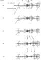
图1是本发明的实施例1的内窥镜的物镜在不同工作距离情况下的广角端、中间状态、远摄端的透镜剖视图。Fig. 1 is a cross-sectional view of the lens of the endoscope objective lens of the
图2是本发明的实施例2的内窥镜的物镜的与图1相同的透镜剖视图。Fig. 2 is a lens cross-sectional view of an objective lens of an endoscope according to a second embodiment of the present invention, similar to Fig. 1 .
图3是本发明的实施例3的内窥镜的物镜的与图1相同的透镜剖视图。3 is a sectional view of an objective lens of an endoscope according to Example 3 of the present invention, similar to that of FIG. 1 .
图4是本发明的实施例4的内窥镜的物镜在广角端改变了工作距离的情况下的、以及在近端的广角端、中间状态、远摄端的透镜剖视图。4 is a cross-sectional view of the objective lens of the endoscope according to Example 4 of the present invention when the working distance is changed at the wide-angle end, and at the wide-angle end at the near end, at the intermediate state, and at the telephoto end.
图5是本发明的实施例5的内窥镜的物镜的与图1相同的透镜剖视图。Fig. 5 is a lens sectional view of an objective lens of an endoscope according to a fifth embodiment of the present invention, similar to Fig. 1 .
图6是本发明的实施例6的内窥镜的物镜的与图1相同的透镜剖视图。Fig. 6 is a lens cross-sectional view of an objective lens of an endoscope according to a sixth embodiment of the present invention, similar to Fig. 1 .
图7是本发明的实施例6的内窥镜的物镜的与图1相同的透镜剖视图。Fig. 7 is a lens sectional view of an objective lens of an endoscope according to a sixth embodiment of the present invention, similar to Fig. 1 .
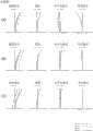
图8是表示实施例1的图1的(a)~(c)的状态下的球面像差、像散、倍率色像差、畸变像差的图。8 is a diagram showing spherical aberration, astigmatism, chromatic aberration of magnification, and distortion aberration in the states of (a) to (c) of FIG. 1 in Example 1. FIG.
图9是表示实施例1的图1的(d)~(f)的状态下的球面像差、像散、倍率色像差、畸变像差的图。9 is a diagram showing spherical aberration, astigmatism, lateral chromatic aberration, and distortion aberration in the states shown in (d) to (f) of FIG. 1 in Example 1. FIG.
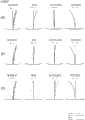
图10是实施例2的与图8相同的图。FIG. 10 is the same diagram as FIG. 8 of the second embodiment.
图11是实施例2的与图9相同的图。FIG. 11 is the same view as FIG. 9 of the second embodiment.
图12是实施例3的与图8相同的图。FIG. 12 is the same view as FIG. 8 of the third embodiment.
图13是实施例3的与图9相同的图。FIG. 13 is the same view as FIG. 9 of the third embodiment.
图14是表示实施例4的图4的(a)~(c)的状态下的球面像差、像散、倍率色像差、畸变像差的图。14 is a diagram showing spherical aberration, astigmatism, lateral chromatic aberration, and distortion aberration in the states of (a) to (c) of FIG. 4 in Example 4. FIG.
图15是表示实施例4的图4的(c)~(e)的状态下的球面像差、像散、倍率色像差、畸变像差的图。15 is a diagram showing spherical aberration, astigmatism, chromatic aberration of magnification, and distortion aberration in the states of (c) to (e) of FIG. 4 in Example 4. FIG.
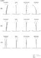
图16是实施例5的与图14相同的图。FIG. 16 is the same view as FIG. 14 of Embodiment 5. FIG.
图17是实施例5的与图15相同的图。FIG. 17 is the same view as FIG. 15 of Embodiment 5. FIG.
图18是实施例6的与图14相同的图。FIG. 18 is the same view as FIG. 14 of Embodiment 6. FIG.
图19是实施例6的与图15相同的图。Fig. 19 is the same view as Fig. 15 of the sixth embodiment.
图20是实施例7的与图14相同的图。Fig. 20 is the same view as Fig. 14 of the seventh embodiment.
图21是实施例7的与图15相同的图。Fig. 21 is the same view as Fig. 15 of the seventh embodiment.
具体实施方式Detailed ways
以下,说明本发明的内窥镜的物镜的实施例1~7。Hereinafter, Examples 1 to 7 of the objective lens of the endoscope of the present invention will be described.
在图1中分别示出实施例1的内窥镜的物镜的工作距离为远端(a)~(c)、及近端(d)~(f)的情况下的广角端(a)、(d)、中间状态(b)、(e)、远摄端(c)、(f)的透镜剖视图。以G1表示该物镜的第1透镜组,以G2表示第2透镜组,以G3表示第3透镜组,以G31表示第3透镜组G3的第3-1透镜组,以G32表示第3-2透镜组。此外,以S表示孔径光阑,以I表示像面。而且,图中的P表示假想激光截止滤光片,红外截止滤光片,光学低通滤光器等光学构件,C表示玻璃盖片,D表示CCD芯片密封玻璃,F表示杂光光阑。在图1的(a)~(b)、(b)~(c)中,箭头概略地表示透镜组的移动方向,图1的(d)中的箭头表示将工作距离自远端改变到近端时的透镜组的移动方向。另外,在这些透镜剖视图(a)~(c)中,为了使附图简单化,仅在图1的(a)中示出以上的附图标记,而在其他附图中省略表示。而且在附图中省略了光学面的面编号及面间隔。另外,以上的附图标记、箭头、图示方法在其他实施例2~7(图2~图7)中也相同。In Fig. 1, the working distances of the objective lens of the endoscope according to Example 1 are respectively shown at the wide-angle end (a), when the working distance is the far end (a) to (c), and at the near end (d) to (f). (d), Lens sectional view of intermediate state (b), (e), telephoto end (c), (f). G1 represents the first lens group of the objective lens, G2 represents the second lens group, G3 represents the third lens group, G31 represents the 3-1 lens group of the third lens group G3, and G32 represents the 3-2 lens group. In addition, an aperture stop is represented by S, and an image plane is represented by I. Moreover, P in the figure represents optical components such as a virtual laser cut filter, an infrared cut filter, and an optical low-pass filter, C represents a cover glass, D represents CCD chip sealing glass, and F represents a stray light stop. In Fig. 1 (a) ~ (b), (b) ~ (c), the arrows roughly indicate the moving direction of the lens group, and the arrows in Fig. 1 (d) represent changing the working distance from the far end to the near end. The direction of movement of the lens group at the end. In addition, in these lens cross-sectional views (a) to (c), in order to simplify the drawings, the above reference numerals are shown only in (a) of FIG. 1 , and are omitted in other drawings. In addition, in the drawings, the surface numbers and surface intervals of the optical surfaces are omitted. In addition, the above reference numerals, arrows, and illustration methods are also the same in other Examples 2 to 7 (FIGS. 2 to 7).
另外,在后述中说明实施例1~7的数值数据,关于面编号,以“No”表示自第1透镜组G1的顶端面起数的光学面的面编号,以“r”表示曲率半径,以“d”表示面间隔或空气间隔,以“nd”表示d线的折射率,以“vd”表示阿贝数。曲率半径、面间隔、焦距的单位为mm。In addition, the numerical data of Examples 1 to 7 will be described later. Regarding the surface number, "No" represents the surface number of the optical surface counted from the front end surface of the first lens group G1, and "r" represents the radius of curvature. , "d" means the plane interval or air interval, "nd" means the refractive index of the d line, and "vd" means the Abbe number. The units of the radius of curvature, surface spacing, and focal length are mm.
如图1所示,实施例1的内窥镜的物镜包括正的第1透镜组G1、负的第2透镜组G2、以及正的第3透镜组G3,该第1透镜组G1包括平凹负透镜、凸面朝向物体侧的负凹凸透镜与双凸正透镜的接合透镜、以及双凸正透镜,该第2透镜组G2在物体侧一体地配置有孔径光阑S并包括凹面朝向物体侧的正凹凸透镜与双凹负透镜的接合透镜,该第3透镜组G3包括双凸正透镜与凹面朝向物体侧的负凹凸透镜的接合透镜、以及双凸正透镜与凹面朝向物体侧的负凹凸透镜的接合透镜,第3透镜组G3的物体侧的接合透镜构成正的第3-1透镜组G31,像侧的接合透镜构成正的第3-2透镜组G32。另外,在第1透镜组G1的平凹负透镜与接合透镜之间以及在第3透镜组G3的像侧配置有激光截止滤光片等光学构件P,在其第3透镜组G3的像侧的光学构件P的像侧接合有玻璃盖片C和CCD芯片密封玻璃D,像面I位于CCD芯片密封玻璃D的背后。此外,用后述的数值数据中的面编号3、6、10、13、18、22、26、27、30、31表示的平面为杂光光阑F。As shown in Figure 1, the objective lens of the endoscope of
图1的(a)是在广角端下工作距离为30mm的远端,(b)是在中间状态下工作距离为30mm的远端,(c)是在远摄端下工作距离为30mm的远端,(d)是在广角端下工作距离为15mm的近端,(e)是在中间状态下工作距离为15mm的近端,(f)是在远摄端下工作距离为15mm的近端。在远端,自广角端成为远摄端的期间,第1透镜组G1、第3-2透镜组G32固定,第2透镜组G2单调地向像侧移动,第3-1透镜组G31一边减少其与第2透镜组G2之间的间隔一边向像侧移动直到成为中间状态,并自中间状态成为远摄端的期间向物体侧移动,在广角端和远端成为相同的位置。Figure 1 (a) is the far end with a working distance of 30mm at the wide-angle end, (b) is the far end with a working distance of 30mm at the intermediate state, and (c) is the far end with a working distance of 30mm at the telephoto end end, (d) is the near end with a working distance of 15mm at the wide-angle end, (e) is the near end with a working distance of 15mm at the intermediate state, (f) is the near end with a working distance of 15mm at the telephoto end . At the telephoto end, from the wide-angle end to the telephoto end, the first lens group G1 and the 3-2 lens group G32 are fixed, the second lens group G2 moves monotonously toward the image side, and the 3-1 lens group G31 reduces its The distance from the second lens group G2 moves toward the image side until it becomes an intermediate state, and moves toward the object side while the intermediate state becomes the telephoto end, and becomes the same position at the wide-angle end and the telephoto end.
当自远端向近端改变工作距离时,在图1的(a)~(c)各自的状态下,向像侧移动第3-1透镜组G31。即,在近端,自广角端成为远摄端的期间,第2透镜组G2与远端的情况相同地单调地向像侧移动,第3-1透镜组G31与远端的情况不同,按照比远端的轨迹靠近像侧的轨迹移动。该移动是使第3-1透镜组G31一边减少其与第2透镜组G2之间的间隔一边向像侧移动直到成为中间状态,并在自中间状态成为远摄端的期间向物体侧移动,在远摄端位于比广角端靠近像侧的位置。When changing the working distance from the far end to the near end, the 3-1 lens group G31 is moved to the image side in each state of (a) to (c) of FIG. 1 . That is, at the near end, when changing from the wide-angle end to the telephoto end, the second lens group G2 monotonously moves toward the image side as in the case of the telephoto end, and the 3-1 lens group G31 is different from the case of the telephoto end in that The track at the far end moves closer to the track at the image side. This movement is to make the 3-1 lens group G31 move toward the image side while reducing the distance between it and the second lens group G2 until it becomes an intermediate state, and move toward the object side while the intermediate state becomes the telephoto end. The telephoto end is located closer to the image side than the wide-angle end.
在图8的(a)、(b)、(c)中示出该实施例1在图1的(a)、(b)、(c)状态下的像差曲线图,在图9的(a)、(b)、(c)中示出在图1的(d)、(e)、(f)状态下的像差曲线图。在像差曲线图中,除了畸变像差以外,横轴为像差量(mm)。此外,畸变像差的横轴为像差量(%)。此外,“FIY”为像高(mm)。此外,像差曲线的波长单位为nm。以下相同。(a), (b) and (c) of FIG. 8 show the aberration curves of this
接着,在图2中示出实施例2的内窥镜的物镜的与图1相同的透镜剖视图。以G1表示该物镜的第1透镜组,以G2表示第2透镜组,以G3表示第3透镜组,以G11表示第1透镜组G1的第1-1透镜组,以G12表示第1-2透镜组,以G31表示第3透镜组G3的第3-1透镜组,以G32表示第3-2透镜组。Next, FIG. 2 shows a lens cross-sectional view of the objective lens of the endoscope of Example 2, which is the same as FIG. 1 . G1 represents the first lens group of the objective lens, G2 represents the second lens group, G3 represents the third lens group, G11 represents the 1st-1st lens group of the first lens group G1, and G12 represents the 1st-2nd lens group As for the lens groups, G31 represents the 3-1 lens group of the third lens group G3, and G32 represents the 3-2 lens group.
如图2所示,实施例2的内窥镜的物镜包括正的第1透镜组G1、负的第2透镜组G2、以及正的第3透镜组G3,该第1透镜组G1包括平凹负透镜、双凹负透镜与双凸正透镜的接合透镜、以及双凸正透镜,该第2透镜组G2在物体侧一体地配置有孔径光阑S并包括凹面朝向物体侧的正凹凸透镜与双凹负透镜的接合透镜,该第3透镜组G3包括双凸正透镜与凹面朝向物体侧的负凹凸透镜的接合透镜、以及双凸正透镜与凹面朝向物体侧的负凹凸透镜的接合透镜,第1透镜组G1的平凹负透镜构成负的第1-1透镜组G11,接合透镜与双凸正透镜构成正的第1-2透镜组G12,第3透镜组G3的物体侧的接合透镜构成正的第3-1透镜组G31,像侧的接合透镜构成正的第3-2透镜组G32。另外,在第1透镜组G1的平凹负透镜与接合透镜之间以及在第3透镜组G3的像侧配置有激光截止滤光片等光学构件P,在其第3透镜组G3的像侧的光学构件P的像侧接合有玻璃盖片C和CCD芯片密封玻璃D,像面I位于CCD芯片密封玻璃D的背后。此外,用后述的数值数据中的面编号3、6、10、13、18、22、26、27、30、31表示的平面为杂光光阑F。As shown in Figure 2, the objective lens of the endoscope of embodiment 2 includes positive first lens group G1, negative second lens group G2, and positive third lens group G3, and this first lens group G1 includes plano-concave A negative lens, a cemented lens of a biconcave negative lens and a biconvex positive lens, and a biconvex positive lens. The second lens group G2 is integrally provided with an aperture stop S on the object side and includes a positive concave-convex lens with a concave surface facing the object side and a positive concave-convex lens. A cemented lens of a biconcave negative lens, the third lens group G3 includes a cemented lens of a biconvex positive lens and a negative meniscus lens whose concave surface faces the object side, and a cemented lens of a biconvex positive lens and a negative meniscus lens whose concave surface faces the object side, The plano-concave negative lens of the first lens group G1 constitutes the negative 1-1 lens group G11, the cemented lens and the biconvex positive lens constitute the positive 1-2 lens group G12, and the cemented lens of the object side of the third lens group G3 The positive 3-1 lens group G31 is constituted, and the cemented lens on the image side constitutes the positive 3-2 lens group G32. In addition, between the plano-concave negative lens and the cemented lens of the first lens group G1 and on the image side of the third lens group G3, optical members P such as laser cut filters are disposed, and on the image side of the third lens group G3 The image side of the optical member P is bonded with a cover glass C and a CCD chip sealing glass D, and the image plane I is located behind the CCD chip sealing glass D. In addition, planes represented by
图2的(a)是在广角端下工作距离为30mm的远端,(b)是在中间状态下工作距离为30mm的远端,(c)是在远摄端下工作距离为30mm的远端,(d)是在广角端下工作距离为15mm的近端,(e)是在中间状态下工作距离为15mm的近端,(f)是在远摄端下工作距离为15mm的近端。在远端,在自广角端成为远摄端的期间,第1-1透镜组G11、第3透镜组G3固定,第1-2透镜组G12单调地向物体侧移动,第2透镜组G2单调地向像侧移动。Figure 2 (a) is the far end with a working distance of 30mm at the wide-angle end, (b) is the far end with a working distance of 30mm at the intermediate state, and (c) is the far end with a working distance of 30mm at the telephoto end end, (d) is the near end with a working distance of 15mm at the wide-angle end, (e) is the near end with a working distance of 15mm at the intermediate state, (f) is the near end with a working distance of 15mm at the telephoto end . At the telephoto end, the 1st-1st lens group G11 and the 3rd lens group G3 are fixed, the 1st-2nd lens group G12 moves monotonously toward the object side, and the 2nd lens group G2 monotonously moves from the wide-angle end to the telephoto end. Move to the image side.
当自远端向近端改变工作距离时,在图2的(a)~(c)各自的状态下,向像侧移动第3-1透镜组G31。When changing the working distance from the far end to the near end, the 3-1 lens group G31 is moved to the image side in each state of (a) to (c) of FIG. 2 .
在图10的(a)、(b)、(c)中示出该实施例2在图2的(a)、(b)、(c)状态下的像差曲线图,在图11的(a)、(b)、(c)中示出在图2的(d)、(e)、(f)状态下的像差曲线图。(a), (b) and (c) of FIG. 10 show the aberration graphs of this embodiment 2 in the states of (a), (b) and (c) of FIG. 2 , and in (a) of FIG. 11 ( a), (b), and (c) show aberration graphs in the states (d), (e), and (f) of FIG. 2 .
接着,在图3中示出实施例3的内窥镜的物镜的与图1相同的透镜剖视图。以G1表示该物镜的第1透镜组,以G2表示第2透镜组,以G3表示第3透镜组,以G11表示第1透镜组G1的第1-1透镜组,以G12表示第1-2透镜组,以G31表示第3透镜组G3的第3-1透镜组,以G32表示第3-2透镜组。Next, FIG. 3 shows a lens cross-sectional view of the objective lens of the endoscope of Example 3, which is the same as FIG. 1 . G1 represents the first lens group of the objective lens, G2 represents the second lens group, G3 represents the third lens group, G11 represents the 1st-1st lens group of the first lens group G1, and G12 represents the 1st-2nd lens group As for the lens groups, G31 represents the 3-1 lens group of the third lens group G3, and G32 represents the 3-2 lens group.
如图3所示,实施例3的内窥镜的物镜包括正的第1透镜组G1、负的第2透镜组G2、以及正的第3透镜组G3,该第1透镜组G1包括平凹负透镜、凸面朝向物体侧的负凹凸透镜与双凸正透镜的接合透镜、以及双凸正透镜,该第2透镜组G2在物体侧一体地配置有孔径光阑S并包括凹面朝向物体侧的正凹凸透镜与双凹负透镜的接合透镜,该第3透镜组G3包括双凸正透镜与凹面朝向物体侧的负凹凸透镜的接合透镜、以及双凸正透镜与凹面朝向物体侧的负凹凸透镜的接合透镜,第1透镜组G1的平凹负透镜构成负的第1-1透镜组G11,接合透镜与双凸正透镜构成正的第1-2透镜组G12,第3透镜组G3的物体侧的接合透镜构成正的第3-1透镜组G31,像侧的接合透镜构成正的第3-2透镜组G32。另外,在第1透镜组G1的平凹负透镜与接合透镜之间以及在第3透镜组G3的像侧配置有激光截止滤光片等光学构件P,在其第3透镜组G3的像侧的光学构件P的像侧接合有玻璃盖片C和CCD芯片密封玻璃D,像面I位于CCD芯片密封玻璃D的背后。此外,用后述的数值数据中的面编号3、6、10、13、18、22、26、27、30、31表示的平面为杂光光阑F。As shown in Figure 3, the objective lens of the endoscope of embodiment 3 comprises positive first lens group G1, negative second lens group G2, and positive third lens group G3, and this first lens group G1 includes plano-concave A negative lens, a cemented lens of a negative meniscus lens with a convex surface facing the object side and a biconvex positive lens, and a biconvex positive lens, the second lens group G2 is integrally provided with an aperture stop S on the object side and includes a A cemented lens of a positive meniscus lens and a biconcave negative lens, the third lens group G3 includes a cemented lens of a biconvex positive lens and a negative meniscus lens whose concave surface faces the object side, and a biconvex positive lens and a negative meniscus lens whose concave surface faces the object side The cemented lens, the plano-concave negative lens of the first lens group G1 constitutes the negative 1-1 lens group G11, the cemented lens and the biconvex positive lens constitute the positive 1-2 lens group G12, the object of the third lens group G3 The cemented lens on the side constitutes a positive 3-1 lens group G31, and the cemented lens on the image side constitutes a positive 3-2 lens group G32. In addition, between the plano-concave negative lens and the cemented lens of the first lens group G1 and on the image side of the third lens group G3, optical members P such as laser cut filters are disposed, and on the image side of the third lens group G3 The image side of the optical member P is bonded with a cover glass C and a CCD chip sealing glass D, and the image plane I is located behind the CCD chip sealing glass D. In addition, planes represented by
图3(a)是在广角端下工作距离为30mm的远端,(b)是在中间状态下工作距离为30mm的远端,(c)是在远摄端下工作距离为30mm的远端,(d)是在广角端下工作距离为15mm的近端,(e)是在中间状态下工作距离为15mm的近端,(f)是在远摄端下工作距离为15mm的近端。在远端,自广角端成为远摄端的期间,第1-1透镜组G11、第3-2透镜组G32固定,第1-2透镜组G12单调地向物体侧移动,第2透镜组G2单调地向像侧移动,第3-1透镜组G31一边减少其与第2透镜组G2之间的间隔一边向像侧移动直到成为中间状态,并在自中间状态成为远摄端的期间一边减少其与第2透镜组G2之间的间隔一边向物体侧移动,在远摄端位于比广角端靠物体侧的位置。Figure 3(a) is the far end with a working distance of 30mm at the wide-angle end, (b) is the far end with a working distance of 30mm at the intermediate state, and (c) is the far end with a working distance of 30mm at the telephoto end , (d) is the near end with a working distance of 15mm at the wide-angle end, (e) is the near end with a working distance of 15mm at the intermediate state, and (f) is the near end with a working distance of 15mm at the telephoto end. At the tele end, from the wide-angle end to the telephoto end, the 1-1st lens group G11 and the 3-2nd lens group G32 are fixed, the 1st-2nd lens group G12 moves monotonously toward the object side, and the 2nd lens group G2 monotonously 3-1 lens group G31 moves toward the image side while reducing the distance between it and the second lens group G2 until it becomes an intermediate state, and reduces its distance from the intermediate state to the telephoto end. The gap between the second lens groups G2 moves toward the object side, and is positioned closer to the object side at the telephoto end than at the wide-angle end.
当自远端向近端改变工作距离时,在图3的(a)~(c)各自的状态下,向像侧移动第3-1透镜组G31。即,在近端,在自广角端成为远摄端的期间,第1-2透镜组G12和第2透镜组G2与远端的情况相同地单调地向像侧移动,第3-1透镜组G31与远端的情况不同,按照比远端的轨迹靠近像侧的轨迹移动。该移动是使第3-1透镜组G31一边减少其与第2透镜组G2之间的间隔一边向像侧移动直到成为中间状态,并在自中间状态成为远摄端的期间向物体侧移动,在远摄端位于比广角端稍靠像侧的位置。When changing the working distance from the far end to the near end, the 3-1 lens group G31 is moved to the image side in each state of (a) to (c) of FIG. 3 . That is, at the near end, during the period from the wide-angle end to the telephoto end, the 1-2 lens group G12 and the second lens group G2 move monotonously to the image side as in the case of the far end, and the 3-1 lens group G31 Unlike the case of the far end, it moves along a trajectory closer to the image side than the trajectory of the far end. This movement is to make the 3-1 lens group G31 move toward the image side while reducing the distance between it and the second lens group G2 until it becomes an intermediate state, and move toward the object side while the intermediate state becomes the telephoto end. The telephoto end is located slightly closer to the image side than the wide-angle end.
在图12的(a)、(b)、(c)中示出该实施例3在图3的(a)、(b)、(c)状态下的像差曲线图,在图13的(a)、(b)、(c)中示出在图3的(d)、(e)、(f)状态下的像差曲线图。(a), (b) and (c) of FIG. 12 show the aberration curves of this embodiment 3 in the states of (a), (b) and (c) of FIG. 3 , and in ( a), (b), and (c) show aberration graphs in the states (d), (e), and (f) of FIG. 3 .
在图4中示出实施例4的内窥镜的物镜的工作距离为远端、中间距离及近端的情况下的、各自在广角端的透镜剖视图(a)、(b)、(c)、以及工作距离为近端的情况下的、在中间状态与远摄端的透镜剖视图(d)、(e)。以G1表示该物镜的第1透镜组,以G2表示第2透镜组,以G3表示第3透镜组,以G11表示第1透镜组G1的第1-1透镜组,以G12表示第1-2透镜组。The working distance of the objective lens of the endoscope of embodiment 4 is shown in Fig. 4 under the situation of far end, intermediate distance and near end, lens sectional view (a), (b), (c) respectively at the wide angle end, And the sectional views (d) and (e) of the lens at the intermediate state and the telephoto end when the working distance is at the near end. G1 represents the first lens group of the objective lens, G2 represents the second lens group, G3 represents the third lens group, G11 represents the 1st-1st lens group of the first lens group G1, and G12 represents the 1st-2nd lens group lens group.
如图4所示,实施例4的内窥镜的物镜包括正的第1透镜组G1、负的第2透镜组G2、以及正的第3透镜组G3,该第1透镜组G1包括平凹负透镜、凹面朝向物体侧的正凹凸透镜、以及双凸正透镜与凹面朝向物体侧的负凹凸透镜的接合透镜,该第2透镜组G2在物体侧一体地配置有孔径光阑S并包括凸面朝向物体侧的负凹凸透镜与凸面朝向物体侧的正凹凸透镜的接合透镜,该第3透镜组G3包括双凸正透镜、以及双凸正透镜与凹面朝向物体侧的负凹凸透镜的接合透镜,第1透镜组G1的平凹负透镜与正凹凸透镜构成负的第1-1透镜组G11,接合透镜构成正的第1-2透镜组G12。另外,在第3透镜组G3的像侧配置有激光截止滤光片等光学构件P,在其第3透镜组G3的像侧的光学构件P的像侧接合有玻璃盖片C和CCD芯片密封玻璃D,像面I位于CCD芯片密封玻璃D的背后。此外,用后述的数值数据中的面编号3、15、16、22表示的平面为杂光光阑F。As shown in Figure 4, the objective lens of the endoscope of embodiment 4 comprises positive first lens group G1, negative second lens group G2, and positive third lens group G3, and this first lens group G1 includes plano-concave A negative lens, a positive meniscus lens with a concave surface facing the object side, and a cemented lens of a biconvex positive lens and a negative meniscus lens with a concave surface facing the object side, the second lens group G2 is integrally provided with an aperture stop S on the object side and includes a convex surface A cemented lens of a negative meniscus lens facing the object side and a positive meniscus lens whose convex surface faces the object side, the third lens group G3 includes a biconvex positive lens and a cemented lens of a biconvex positive lens and a negative meniscus lens whose concave surface faces the object side, The plano-concave negative lens and the positive meniscus lens of the first lens group G1 constitute a negative 1-1 lens group G11, and the cemented lens constitutes a positive 1-2 lens group G12. In addition, on the image side of the third lens group G3, optical components P such as laser cut filters are arranged, and the image side of the optical components P on the image side of the third lens group G3 is bonded with a cover glass C and a CCD chip seal. Glass D, the image plane I is located behind the sealing glass D of the CCD chip. In addition, planes represented by plane numbers 3, 15, 16, and 22 in numerical data described later are the stray light stops F. FIG.
图4(a)是在广角端下工作距离为15mm的远端,(b)是在广角端下工作距离为5mm的中间距离,(c)是在广角端下工作距离为2.47641mm的近端,(d)是在工作距离为2.47641mm的近端为中间状态,(e)是在工作距离为2.47641mm的近端为远摄端。在近端,在自广角端成为远摄端的期间,第1-1透镜组G11、第3透镜组G3固定,第1-2透镜组G12单调地向物体侧移动,第2透镜组G2一边扩宽其与第1-2透镜组G12之间的间隔一边单调地向物体侧移动((c)~(e))。Figure 4(a) is the far end with a working distance of 15mm at the wide-angle end, (b) is the middle distance with a working distance of 5mm at the wide-angle end, and (c) is the near end with a working distance of 2.47641mm at the wide-angle end , (d) is the intermediate state at the near end of the working distance of 2.47641mm, and (e) is the telephoto end at the near end of the working distance of 2.47641mm. At the near end, during the period from the wide-angle end to the telephoto end, the 1-1 lens group G11 and the 3rd lens group G3 are fixed, the 1-2 lens group G12 moves monotonously to the object side, and the 2nd lens group G2 expands It moves toward the object side monotonously while increasing the distance between it and the first-second lens group G12 ((c) to (e)).
当在广角端自远端向近端改变工作距离时,向像侧移动第2透镜组G2((a)~(c))。When changing the working distance from the far end to the near end at the wide-angle end, the second lens group G2 is moved toward the image side ((a) to (c)).
在图14的(a)、(b)、(c)中示出该实施例4在图4的(a)、(b)、(c)状态下的像差曲线图,在图15的(a)、(b)、(c)中示出在图4的(c)、(d)、(e)状态下的像差曲线图。(a), (b) and (c) of FIG. 14 show the aberration curves of this embodiment 4 in the state of (a), (b) and (c) of FIG. 4 , and in (a) of FIG. 15 a), (b), and (c) show aberration graphs in the states of (c), (d), and (e) in FIG. 4 .
接着,在图5中示出实施例5的内窥镜的物镜的与图4相同的透镜剖视图。以G1表示该物镜的第1透镜组,以G2表示第2透镜组,以G3表示第3透镜组,以G21表示第2透镜组G2的第2-1透镜组,以G22表示第2-2透镜组。Next, FIG. 5 shows a lens cross-sectional view of the objective lens of the endoscope of Example 5, which is the same as FIG. 4 . G1 represents the first lens group of the objective lens, G2 represents the second lens group, G3 represents the third lens group, G21 represents the 2nd-1 lens group of the second lens group G2, and G22 represents the 2-2nd lens group lens group.
如图5所示,实施例5的内窥镜的物镜包括正的第1透镜组G1、负的第2透镜组G2、以及正的第3透镜组G3,该第1透镜组G1包括平凹负透镜、凹面朝向物体侧的正凹凸透镜、以及双凸正透镜与凹面朝向物体侧的负凹凸透镜的接合透镜,该第2透镜组G2在物体侧配置有孔径光阑S并包括凹面朝向物体侧的负凹凸透镜、以及凸面朝向物体侧的负凹凸透镜与凸面朝向物体侧的负凹凸透镜的接合透镜,该第3透镜组G3包括双凸正透镜、以及凹面朝向物体侧的正凹凸透镜与凹面朝向物体侧的负凹凸透镜的接合透镜,第2透镜组G2的单独的负凹凸透镜构成负的第2-1透镜组G21,接合透镜构成负的第2-2透镜组G22。孔径光阑S一体地配置于单独的负凹凸透镜的物体侧。另外,在第3透镜组G3的像侧配置有激光截止滤光片等光学构件P,在其第3透镜组G3的像侧的光学构件P的像侧接合有玻璃盖片C和CCD芯片密封玻璃D,像面I位于CCD芯片密封玻璃D的背后。此外,用后述的数值数据中的面编号3、4、5、19、20、26表示的平面为杂光光阑F。As shown in Figure 5, the objective lens of the endoscope of embodiment 5 comprises positive first lens group G1, negative second lens group G2, and positive third lens group G3, and this first lens group G1 includes plano-concave A negative lens, a positive meniscus lens with a concave surface facing the object side, and a cemented lens of a biconvex positive lens and a negative meniscus lens with a concave surface facing the object side, the second lens group G2 is provided with an aperture stop S on the object side and includes a concave surface facing the object The negative meniscus lens on the negative side, and the cemented lens of the negative meniscus lens with the convex surface facing the object side and the negative meniscus lens with the convex surface facing the object side, the third lens group G3 includes a biconvex positive lens, a positive meniscus lens with a concave surface facing the object side and The cemented lens of the negative meniscus lens with the concave surface facing the object side, the single negative meniscus lens of the second lens group G2 constitutes the negative 2-1 lens group G21, and the cemented lens constitutes the negative 2-2 lens group G22. The aperture stop S is integrally arranged on the object side of the single negative meniscus lens. In addition, on the image side of the third lens group G3, optical components P such as laser cut filters are arranged, and the image side of the optical components P on the image side of the third lens group G3 is bonded with a cover glass C and a CCD chip seal. Glass D, the image plane I is located behind the sealing glass D of the CCD chip. In addition, planes represented by
图5的(a)是在广角端下工作距离为15mm的远端,(b)是在广角端下工作距离为2.5mm的中间距离,(c)是在广角端下工作距离为1.58mm的近端,(d)是在工作距离为1.58mm的近端为中间状态,(e)是在工作距离为1.58mm的近端为远摄端。在近端,在自广角端成为远摄端的期间,第1透镜组G1固定,第2-1透镜组G21单调地向物体侧移动,第2-2透镜组G22单调地向像侧移动,第3透镜组G3一边扩宽其与第2-2透镜组G22之间的间隔一边单调地向像侧移动((c)~(e))。Figure 5 (a) is the far end with a working distance of 15mm at the wide-angle end, (b) is the middle distance with a working distance of 2.5mm at the wide-angle end, and (c) is the working distance at the wide-angle end of 1.58mm Near end, (d) is the intermediate state at the near end with the working distance of 1.58mm, and (e) is the telephoto end at the near end with the working distance of 1.58mm. At the near end, during the period from the wide-angle end to the telephoto end, the first lens group G1 is fixed, the 2-1st lens group G21 moves monotonously to the object side, the 2-2nd lens group G22 moves monotonously to the image side, and the 2nd-1st lens group G22 moves monotonously to the image side. The 3-lens group G3 moves toward the image side monotonously while widening the distance from the 2-2 lens group G22 ((c) to (e)).
当在广角端自远端向近端改变工作距离时,向像侧移动第2-2透镜组G22((a)~(c)))。When changing the working distance from the far end to the near end at the wide-angle end, the 2-2 lens group G22 is moved toward the image side ((a) to (c))).
在图16的(a)、(b)、(c)中示出该实施例5在图5的(a)、(b)、(c)状态下的像差曲线图,在图17的(a)、(b)、(c)中示出在图5的(c)、(d)、(e)状态下的像差曲线图。(a), (b) and (c) of FIG. 16 show the aberration curve diagrams of this embodiment 5 in the states of (a), (b) and (c) of FIG. 5 , and in ( a), (b), and (c) show aberration graphs in the states (c), (d), and (e) of FIG. 5 .
接着,在图6中示出实施例6的内窥镜的物镜的与图4相同的透镜剖视图。以G1表示该物镜的第1透镜组,以G2表示第2透镜组,以G3表示第3透镜组,以G21表示第2透镜组G2的第2-1透镜组,以G22表示第2-2透镜组。Next, FIG. 6 shows a lens cross-sectional view of the objective lens of the endoscope according to the sixth embodiment, which is the same as that in FIG. 4 . G1 represents the first lens group of the objective lens, G2 represents the second lens group, G3 represents the third lens group, G21 represents the 2nd-1 lens group of the second lens group G2, and G22 represents the 2-2nd lens group lens group.
如图6所示,实施例6的内窥镜的物镜包括正的第1透镜组G1、负的第2透镜组G2、以及正的第3透镜组G3,该第1透镜组G1包括平凹负透镜、凹面朝向物体侧的正凹凸透镜、以及双凸正透镜与凹面朝向物体侧的负凹凸透镜的接合透镜,该第2透镜组G2包括双凸正透镜以及双凹负透镜与凸面朝向物体侧的正凹凸透镜的接合透镜并在该双凸正透镜和该接合透镜之间配置有孔径光阑S,该第3透镜组G3包括双凸正透镜、以及双凸正透镜与凹面朝向物体侧的负凹凸透镜的接合透镜,第2透镜组G2的双凸正透镜构成正的第2-1透镜组G21,接合透镜构成负的第2-2透镜组G22。孔径光阑S配置在接合透镜的最靠物体侧的透镜面的面顶位置。另外,在第3透镜组G3的像侧配置有激光截止滤光片等光学构件P,在其第3透镜组G3的像侧的光学构件P的像侧接合有玻璃盖片C和CCD芯片密封玻璃D,像面I位于CCD芯片密封玻璃D的背后。此外,用后述的数值数据中的面编号3、4、5、11、19、20、26表示的平面为杂光光阑F。As shown in Figure 6, the objective lens of the endoscope of embodiment 6 includes positive first lens group G1, negative second lens group G2, and positive third lens group G3, and this first lens group G1 includes plano-concave A negative lens, a positive meniscus lens with a concave surface facing the object side, and a cemented lens of a biconvex positive lens and a negative meniscus lens with a concave surface facing the object side. The second lens group G2 includes a biconvex positive lens and a double concave negative lens with a convex surface facing the object. The cemented lens of the positive concave-convex lens on the side and the aperture stop S is arranged between the double convex positive lens and the cemented lens, the third lens group G3 includes a double convex positive lens, and a double convex positive lens with a concave surface facing the object side The cemented lens of the negative meniscus lens, the biconvex positive lens of the second lens group G2 constitutes the positive 2-1 lens group G21, and the cemented lens constitutes the negative 2-2 lens group G22. The aperture stop S is arranged at the top position of the lens surface on the most object side of the cemented lens. In addition, on the image side of the third lens group G3, optical components P such as laser cut filters are arranged, and the image side of the optical components P on the image side of the third lens group G3 is bonded with a cover glass C and a CCD chip seal. Glass D, the image plane I is located behind the sealing glass D of the CCD chip. In addition, planes represented by
图6的(a)是在广角端下工作距离为15mm的远端,(b)是在广角端下工作距离为2.5mm的中间距离,(c)是在广角端下工作距离为1.58mm的近端,(d)是在工作距离为1.58mm的近端为中间状态,(e)是在工作距离为1.58mm的近端为远摄端。在近端,在自广角端成为远摄端期间,第1透镜组G1、第3透镜组G3固定,第2-1透镜组G21单调地向像侧移动,第2-2透镜组G22一边减少其与第2-1透镜组G21之间的间隔一边单调地向像侧移动((c)~(e))。Figure 6 (a) is the far end with a working distance of 15mm at the wide-angle end, (b) is the middle distance with a working distance of 2.5mm at the wide-angle end, and (c) is the working distance at the wide-angle end with a working distance of 1.58mm Near end, (d) is the intermediate state at the near end with the working distance of 1.58mm, and (e) is the telephoto end at the near end with the working distance of 1.58mm. At the near end, when changing from the wide-angle end to the telephoto end, the first lens group G1 and the third lens group G3 are fixed, the 2-1st lens group G21 moves monotonously toward the image side, and the 2-2nd lens group G22 decreases The distance between this and the 2-1st lens group G21 moves monotonously toward the image side ((c) to (e)).
当在广角端自远端向近端改变工作距离时,向像侧移动第2-2透镜组G22((a)~(c)))。When changing the working distance from the far end to the near end at the wide-angle end, the 2-2 lens group G22 is moved toward the image side ((a) to (c))).
在图18的(a)、(b)、(c)中示出该实施例6在图6的(a)、(b)、(c)状态下的像差曲线图,在图19的(a)、(b)、(c)中示出在图6的(c)、(d)、(e)状态下的像差曲线图。(a), (b) and (c) of FIG. 18 show the aberration graphs of this embodiment 6 in the states of (a), (b) and (c) of FIG. 6 , and in (a) of FIG. 19 ( a), (b), and (c) show aberration graphs in the states of (c), (d), and (e) in FIG. 6 .
接着,在图7中示出实施例7的内窥镜的物镜的与图4相同的透镜剖视图。以G1表示该物镜的第1透镜组,以G2表示第2透镜组,以G3表示第3透镜组,以G31表示第3透镜组G3的第3-1透镜组,以G32表示第3-2透镜组。Next, FIG. 7 shows a lens cross-sectional view of the objective lens of the endoscope of Example 7, which is the same as FIG. 4 . G1 represents the first lens group of the objective lens, G2 represents the second lens group, G3 represents the third lens group, G31 represents the 3-1 lens group of the third lens group G3, and G32 represents the 3-2 lens group.
如图7所示,实施例7的内窥镜的物镜包括正的第1透镜组G1、负的第2透镜组G2、以及正的第3透镜组G3,该第1透镜组G1包括平凹负透镜、凹面朝向物体侧的正凹凸透镜、以及双凸正透镜与凹面朝向物体侧的负凹凸透镜的接合透镜,该第2透镜组G2在物体侧一体地配置有孔径光阑S并包括双凹负透镜与凸面朝向物体侧的正凹凸透镜的接合透镜,该第3透镜组G3包括两个双凸正透镜、以及双凸正透镜与凹面朝向物体侧的负凹凸透镜的接合透镜,第3透镜组G3的物体侧的两个双凸正透镜构成正的第3-1透镜组G31,接合透镜构成正的第3-2透镜组G32。另外,在第1透镜组G1的平凹负透镜与正凹凸透镜之间以及在第3透镜组G3的像侧配置有激光截止滤光片等光学构件P,在其第3透镜组G3的像侧的光学构件P的像侧接合有玻璃盖片C和CCD芯片密封玻璃D,像面I位于CCD芯片密封玻璃D的背后。此外,用后述的数值数据中的面编号3、4、20、21、27表示的平面为杂光光阑F。As shown in Figure 7, the objective lens of the endoscope of embodiment 7 includes positive first lens group G1, negative second lens group G2, and positive third lens group G3, and this first lens group G1 includes plano-concave A negative lens, a positive meniscus lens with a concave surface facing the object side, and a cemented lens of a biconvex positive lens and a negative meniscus lens with a concave surface facing the object side. The second lens group G2 is integrally provided with an aperture stop S on the object side and includes double A cemented lens of a concave negative lens and a positive meniscus lens whose convex surface faces the object side, the third lens group G3 includes two biconvex positive lenses, and a cemented lens of a biconvex positive lens and a negative meniscus lens whose concave surface faces the object side, the third The two biconvex positive lenses on the object side of the lens group G3 constitute a positive 3-1 lens group G31, and the cemented lenses constitute a positive 3-2 lens group G32. In addition, between the plano-concave negative lens and the positive concave-convex lens of the first lens group G1 and on the image side of the third lens group G3, optical components P such as laser cut filters are arranged. The image side of the optical component P on the side is bonded with a cover glass C and a CCD chip sealing glass D, and the image plane I is located behind the CCD chip sealing glass D. In addition, planes represented by
图7的(a)是在广角端下工作距离为12mm的远端,(b)是在广角端下工作距离为6mm的中间距离,(c)是在广角端下工作距离为3mm的近端,(d)是在工作距离为3mm的近端为中间状态,(e)是在工作距离为3mm的近端为远摄端。在近端,在自广角端成为远摄端的期间,第1透镜组G1、第3-2透镜组G32固定,第2透镜组G2单调地向像侧移动,第3-1透镜组G31一边减少其与第2透镜组G2之间的间隔一边单调地向像侧移动((c)~(e))。Figure 7 (a) is the far end with a working distance of 12mm at the wide-angle end, (b) is the middle distance at the wide-angle end with a working distance of 6mm, and (c) is the near end with a working distance of 3mm at the wide-angle end , (d) is the intermediate state at the near end where the working distance is 3 mm, and (e) is the telephoto end at the near end where the working distance is 3 mm. At the near end, during the period from the wide-angle end to the telephoto end, the first lens group G1 and the 3-2 lens group G32 are fixed, the second lens group G2 moves monotonously to the image side, and the 3-1 lens group G31 decreases The distance between this and the second lens group G2 moves monotonously toward the image side ((c) to (e)).
当在广角端自远端向近端改变工作距离时,向像侧移动第3-1透镜组G31((a)~(c))。When changing the working distance from the far end to the near end at the wide-angle end, the 3-1 lens group G31 is moved toward the image side ((a) to (c)).
在图20的(a)、(b)、(c)中示出该实施例7在图7的(a)、(b)、(c)状态下的像差曲线图,在图21的(a)、(b)、(c)中示出在图7的(c)、(d)、(e)状态下的像差曲线图。(a), (b) and (c) of FIG. 20 show the aberration curve diagrams of this embodiment 7 in the states of (a), (b) and (c) of FIG. 7 , and in (a) of FIG. 21 a), (b), and (c) show aberration graphs in the states of (c), (d), and (e) of FIG. 7 .
以下,示出上述实施例1~7的数值数据。在以下的表中,“INF”表示无穷大。“WD”表示工作距离,“f”表示整个系统的焦距,“2ω”表示视场角(°),“Fno”表示有效F序号,“IH”表示像高。“WF”表示在广角端下工作距离为远端,“MF”表示在中间状态下工作距离为远端,“TF”表示在远摄端下工作距离为远端,“WN”表示在广角端下工作距离为近端,“MN”表示在中间状态下工作距离为近端,“TN”表示在远摄端下工作距离为近端,“WM”表示在广角端下工作距离为中间距离。Numerical data of the above-mentioned Examples 1 to 7 are shown below. In the following tables, "INF" means infinity. "WD" indicates the working distance, "f" indicates the focal length of the entire system, "2ω" indicates the field of view (°), "Fno" indicates the effective F number, and "IH" indicates the image height. "WF" means the working distance is the far end at the wide-angle end, "MF" means the working distance is the far end at the intermediate state, "TF" means the working distance is the far end at the telephoto end, "WN" means the working distance is at the wide-angle end The lower working distance is the near end, "MN" means the working distance is the near end in the intermediate state, "TN" means the working distance is the near end in the telephoto end, and "WM" means the working distance is the middle distance in the wide-angle end.
实施例1Example 1


实施例2Example 2


实施例3Example 3


实施例4Example 4


实施例5Example 5


实施例6Example 6


实施例7Example 7


此外,各实施例中的条件式的值及条件式元素的值如下。In addition, the value of the conditional expression and the value of the element of a conditional expression in each Example are as follows.
另外,实施例5不满足条件式(1)。但是,主要具有变焦作用的第2-2透镜组G22向像侧移动,实质上正的第1透镜组与负的第2透镜组之间的间隔随着自广角侧成为望远侧逐渐变宽。若以(D12t-D12w)作为第2-2透镜组G22的移动量来计算则为1.89,条件式(1)的值成为1.89/fw=1.89/1.478=1.28,满足本发明的思想。In addition, Example 5 does not satisfy conditional expression (1). However, the 2-2 lens group G22, which mainly functions as a zoom, moves toward the image side, and substantially the distance between the positive first lens group and the negative second lens group gradually increases from the wide-angle side to the telephoto side. . When calculated as (D12t-D12w) as the movement amount of the 2-2 lens group G22, it is 1.89, and the value of the conditional expression (1) becomes 1.89/fw=1.89/1.478=1.28, which satisfies the idea of the present invention.
以上的本发明的内窥镜的物镜可以以例如以下方式构成。The above objective lens of the endoscope of the present invention can be configured, for example, as follows.
[1]一种内窥镜的物镜,其特征在于,[1] An objective lens of an endoscope, characterized in that,
上述内窥镜的物镜的广角端的视场角(2ω)为100°以上,The field angle (2ω) of the wide-angle end of the objective lens of the above-mentioned endoscope is 100° or more,
自物体侧起依次具有正的第1透镜组、负的第2透镜组、正的第3透镜组,It has a positive first lens group, a negative second lens group, and a positive third lens group in order from the object side,
第3透镜组包括正的第3-1透镜组和正的第3-2透镜组,The third lens group includes the positive 3-1 lens group and the positive 3-2 lens group,
至少第2透镜组中的透镜组移动,并进行以下(1)、(2);At least the lens group in the second lens group is moved, and the following (1), (2) are performed;
(1)改变整个系统的焦距;以及(1) changing the focal length of the entire system; and
(2)校正焦距变化带来的像位置的移动;(2) Correct the movement of the image position caused by the change of focal length;
第2透镜组、第3透镜组中的一个透镜组以工作距离(WD)自较长的一侧向较短的一侧变化的方式向像侧移动,并进行以下(3):One lens group of the second lens group and the third lens group is moved to the image side in such a manner that the working distance (WD) changes from the longer side to the shorter side, and the following (3) is performed:
(3)校正工作距离的变化带来的焦点位置的移动。(3) Correct the movement of the focus position caused by the change of the working distance.
[2]根据上述1所述的内窥镜的物镜,其特征在于,[2] The objective lens for an endoscope according to the above-mentioned 1, wherein
第2透镜组具有亮度光阑。The second lens group has a brightness stop.
[3]根据上述1所述的内窥镜的物镜,其特征在于,[3] The objective lens for an endoscope according to the above 1, wherein
上述内窥镜的物镜满足以下条件:The objective lens of the above-mentioned endoscope meets the following conditions:
0.4<(D12t-D12w)/fw<1.4 ···(1)0.4<(D12t-D12w)/fw<1.4 ···(1)
0.02<ΔDwd/fw<0.4 ···(2)0.02<ΔDwd/fw<0.4 …(2)
0<(rb+ra)/(rb-ra)<2 ···(3)0<(rb+ra)/(rb-ra)<2···(3)
-0.7<1/βwd<0.2 ···(4)-0.7<1/βwd<0.2 ···(4)
其中,in,
fw为广角端下的整个系统的焦距,是工作距离为远端下的值,fw is the focal length of the entire system at the wide-angle end, and is the value when the working distance is at the far end.
D12w为广角端下的第1透镜组和第2透镜组之间的间隔,D12w is the distance between the first lens group and the second lens group at the wide-angle end,
D12t为远摄端下的第1透镜组和第2透镜组之间的间隔,D12t is the distance between the first lens group and the second lens group at the telephoto end,
ΔDwd为自远端向近端改变工作距离时的移动组的移动量,设向像侧移动的方向为+符号,ΔDwd is the movement amount of the moving group when changing the working distance from the far end to the near end, and the direction of moving to the image side is the + sign,
ra为第1透镜组的第1透镜的像侧面的曲率半径,ra is the radius of curvature of the image side of the first lens of the first lens group,
rb为第1透镜组的第2透镜的物体侧面的曲率半径,rb is the radius of curvature of the object side of the second lens of the first lens group,
βwd为改变工作距离时的移动组的成像倍率,是广角端并且工作距离为远端下的值。βwd is the imaging magnification of the moving group when the working distance is changed, and it is the value at the wide-angle end and the working distance is at the far end.
[4]一种内窥镜的物镜,其特征在于,[4] An objective lens of an endoscope, characterized in that,
上述内窥镜的物镜的广角端的视场角(2ω)为100°以上,The field angle (2ω) of the wide-angle end of the objective lens of the above-mentioned endoscope is 100° or more,
自物体侧起依次具有正的第1透镜组、负的第2透镜组、正的第3透镜组,It has a positive first lens group, a negative second lens group, and a positive third lens group in order from the object side,
第2透镜组具有亮度光阑,The second lens group has a brightness diaphragm,
第3透镜组包括正的第3-1透镜组和正的第3-2透镜组,The third lens group includes the positive 3-1 lens group and the positive 3-2 lens group,
至少第2透镜组中的透镜组移动,并进行以下(1)、(2):At least the lens group in the second lens group is moved, and the following (1), (2) are performed:
(1)改变整个系统的焦距;以及(1) changing the focal length of the entire system; and
(2)校正焦距变化带来的像位置的移动;(2) Correct the movement of the image position caused by the change of focal length;
第2透镜组、第3透镜组中的一个透镜组以工作距离(WD)自较长的一侧向较短的一侧变化的方式向像侧移动,并进行以下(3);One lens group in the second lens group and the third lens group moves to the image side in a manner that the working distance (WD) changes from the longer side to the shorter side, and performs the following (3);
(3)校正工作距离的变化带来的焦点位置的移动,(3) Correct the movement of the focus position caused by the change of the working distance,
上述内窥镜的物镜还满足以下的条件:The objective lens of the above-mentioned endoscope also meets the following conditions:
0.4<(D12t-D12w)/fw<1.4 ···(1)0.4<(D12t-D12w)/fw<1.4 ···(1)
0.02<ΔDwd/fw<0.4 ···(2)0.02<ΔDwd/fw<0.4 …(2)
0<(rb+ra)/(rb-ra)<2 ···(3)0<(rb+ra)/(rb-ra)<2···(3)
-0.7<1/βwd<0.2 ···(4)-0.7<1/βwd<0.2 ···(4)
其中,in,
fw为广角端下的整个系统的焦距,是工作距离为远端下的值,fw is the focal length of the entire system at the wide-angle end, and is the value when the working distance is at the far end.
D12w为广角端下的第1透镜组和第2透镜组之间的间隔,D12w is the distance between the first lens group and the second lens group at the wide-angle end,
D12t为远摄端下的第1透镜组和第2透镜组之间的间隔,D12t is the distance between the first lens group and the second lens group at the telephoto end,
ΔDwd为自远端向近端改变工作距离时的移动组的移动量,设向像侧移动的方向为+符号,ΔDwd is the movement amount of the moving group when changing the working distance from the far end to the near end, and the direction of moving to the image side is the + sign,
ra为第1透镜组的第1透镜的像侧面的曲率半径,ra is the radius of curvature of the image side of the first lens of the first lens group,
rb为第1透镜组的第2透镜的物体侧面的曲率半径,rb is the radius of curvature of the object side of the second lens of the first lens group,
βwd为改变工作距离时的移动组的成像倍率,是广角端并且工作距离为远端下的值。βwd is the imaging magnification of the moving group when the working distance is changed, and it is the value at the wide-angle end and the working distance is at the far end.
[5]根据上述1至4中任一项所述的内窥镜的物镜,其特征在于,[5] The objective lens for an endoscope according to any one of 1 to 4 above, wherein
在进行通常的远处观察之后,将工作距离自较长的一侧改变成较短的一侧并进行近处观察,而且在将工作距离保持在近处的情况下使整个系统的焦距改变,从而能够进行更高倍率的放大观察。After the usual far observation, changing the working distance from the longer side to the shorter side and performing close observation, and changing the focal length of the entire system while keeping the working distance at near, This enables magnified observation at a higher magnification.
[6]根据上述1至4中任一项所述的内窥镜的物镜,其特征在于,[6] The objective lens for an endoscope according to any one of 1 to 4 above, wherein
以自广角侧向望远侧变化的方式,第2透镜组向像侧移动,The second lens group moves to the image side in such a way that it changes from the wide-angle side to the telephoto side,
第3-1透镜组以与第2透镜组不同的轨迹移动,以校正焦距变化带来的像位置的移动,The 3-1 lens group moves on a different trajectory from the 2nd lens group to correct the shift of the image position caused by the focal length change,
第3-1透镜组以工作距离(WD)自较长的一侧向较短的一侧变化的方式向像侧移动。The 3-1st lens group moves toward the image side so that the working distance (WD) changes from the long side to the short side.
[7]根据上述1至4中任一项所述的内窥镜的物镜,其特征在于,[7] The objective lens for an endoscope according to any one of 1 to 4 above, wherein
第1透镜组包括负的第1-1透镜组和正的第1-2透镜组,The first lens group includes negative 1-1 lens group and positive 1-2 lens group,
以自广角侧向望远侧变化的方式,第2透镜组向像侧移动,The second lens group moves to the image side in such a way that it changes from the wide-angle side to the telephoto side,
第1-2透镜组以与第2透镜组不同的轨迹移动,以第1-2透镜组校正焦距变化带来的像位置的移动,The 1st-2nd lens group moves on a different trajectory from the 2nd lens group, and the 1st-2nd lens group corrects the movement of the image position caused by the change of focal length,
第3-1透镜组以工作距离(WD)自较长的一侧向较短的一侧变化的方式向像侧移动。The 3-1st lens group moves toward the image side so that the working distance (WD) changes from the long side to the short side.
[8]根据上述1至4中任一项所述的内窥镜的物镜,其特征在于,[8] The objective lens for an endoscope according to any one of 1 to 4 above, wherein
第1透镜组包括负的第1-1透镜组和正的第1-2透镜组,The first lens group includes negative 1-1 lens group and positive 1-2 lens group,
以自广角侧向望远侧变化的方式,第1-2透镜组向物体侧移动,第2透镜组向像侧移动,In such a way that it changes from the wide-angle side to the telephoto side, the 1st and 2nd lens groups move toward the object side, and the 2nd lens group moves toward the image side,
第3-1透镜组以与第1-2透镜组、第2透镜组不同的轨迹移动,以校正焦距变化带来的像位置的移动,The 3-1 lens group moves in a different trajectory from the 1-2 lens group and the 2nd lens group to correct the movement of the image position caused by the focal length change,
第3-1透镜组以工作距离(WD)自较长的一侧向较短的一侧变化的方式向像侧移动。The 3-1st lens group moves toward the image side so that the working distance (WD) changes from the long side to the short side.
[9]根据上述1至4中任一项所述的内窥镜的物镜,其特征在于,[9] The objective lens for an endoscope according to any one of 1 to 4 above, wherein
第1透镜组包括负的第1-1透镜组和正的第1-2透镜组,The first lens group includes negative 1-1 lens group and positive 1-2 lens group,
以自广角侧向望远侧变化的方式,第1-2透镜组向物体侧移动,The 1st and 2nd lens groups move toward the object side in such a way that it changes from the wide-angle side to the telephoto side,
第2透镜组以与第1-2透镜组不同的轨迹移动,以校正焦距变化带来的像位置的移动,The second lens group moves on a different trajectory from the first-second lens group to correct the movement of the image position caused by the change of focal length,
第2透镜组以工作距离(WD)自较长的一侧向较短的一侧变化的方式向像侧移动。The second lens group moves toward the image side so that the working distance (WD) changes from the long side to the short side.
[10]根据上述1至4中任一项所述的内窥镜的物镜,其特征在于,[10] The objective lens for an endoscope according to any one of 1 to 4 above, wherein
第2透镜组包括负的第2-1透镜组和负的第2-2透镜组,The second lens group includes a negative 2-1 lens group and a negative 2-2 lens group,
以自广角侧向望远侧变化的方式,第2-1透镜组向物体侧移动,第2-2透镜组向像侧移动,The 2-1 lens group moves to the object side, the 2-2 lens group moves to the image side in such a way that it changes from the wide-angle side to the telephoto side,
第3透镜组以与第2-1透镜组、第2-2透镜组不同的轨迹移动,以校正焦距变化带来的像位置的移动,The third lens group moves on a trajectory different from that of the 2-1 lens group and the 2-2 lens group to correct the movement of the image position caused by the focal length change,
第2-2透镜组以工作距离(WD)自较长的一侧向较短的一侧变化的方式向像侧移动。The 2nd-2nd lens group moves toward the image side so that the working distance (WD) changes from the long side to the short side.
[11]根据上述1至4中任一项所述的内窥镜的物镜,其特征在于,[11] The objective lens for an endoscope according to any one of 1 to 4 above, wherein
第2透镜组包括正的第2-1透镜组和负的第2-2透镜组,The second lens group includes a positive 2-1 lens group and a negative 2-2 lens group,
以自广角侧向望远侧变化的方式,第2-2透镜组向像侧移动,The 2-2 lens group moves to the image side in such a way that it changes from the wide-angle side to the telephoto side,
第2-1透镜组以与第2-2透镜组不同的轨迹移动,以校正焦距变化带来的像位置的移动,The 2-1 lens group moves on a different trajectory from the 2-2 lens group to correct the movement of the image position caused by the focal length change,
第2-2透镜组以工作距离(WD)自较长的一侧向较短的一侧变化的方式向像侧移动。The 2nd-2nd lens group moves toward the image side so that the working distance (WD) changes from the long side to the short side.
产业上的可利用性Industrial availability
根据本发明,能够提供一种内窥镜的物镜,该内窥镜的物镜适用于内窥镜并能够分别独立地具有变焦功能和调焦功能,并且能够进行放大观察。According to the present invention, it is possible to provide an objective lens for an endoscope that is suitable for use in an endoscope, can independently have a zoom function and a focus function, and can perform magnified observation.
附图标记的说明Explanation of reference signs
G1第1透镜组;G2第2透镜组;G3第3透镜组;G11第1-1透镜组;G12第1-2透镜组;G21第2-1透镜组;G22第2-2透镜组;G31第3-1透镜组;G32第3-2透镜组;S孔径光阑;I像面;P光学构件(激光截止滤光片,红外截止滤光片,光学低通滤波器等);C玻璃盖片;D CCD芯片密封玻璃;F杂光光阑。
Claims (9)
Applications Claiming Priority (3)
| Application Number | Priority Date | Filing Date | Title |
|---|---|---|---|
| JP2009-126037 | 2009-05-26 | ||
| JP2009126037 | 2009-05-26 | ||
| PCT/JP2010/003079WO2010137238A1 (en) | 2009-05-26 | 2010-04-30 | Objective lens of endoscope |
Publications (2)
| Publication Number | Publication Date |
|---|---|
| CN102428401A CN102428401A (en) | 2012-04-25 |
| CN102428401Btrue CN102428401B (en) | 2014-06-25 |
Family
ID=43222370
Family Applications (1)
| Application Number | Title | Priority Date | Filing Date |
|---|---|---|---|
| CN201080021667.XAExpired - Fee RelatedCN102428401B (en) | 2009-05-26 | 2010-04-30 | Objective lens of endoscope |
Country Status (5)
| Country | Link |
|---|---|
| US (1) | US8164836B2 (en) |
| EP (1) | EP2437094B1 (en) |
| JP (1) | JP4834799B2 (en) |
| CN (1) | CN102428401B (en) |
| WO (1) | WO2010137238A1 (en) |
Families Citing this family (64)
| Publication number | Priority date | Publication date | Assignee | Title |
|---|---|---|---|---|
| US8926502B2 (en) | 2011-03-07 | 2015-01-06 | Endochoice, Inc. | Multi camera endoscope having a side service channel |
| US9642513B2 (en) | 2009-06-18 | 2017-05-09 | Endochoice Inc. | Compact multi-viewing element endoscope system |
| US9492063B2 (en) | 2009-06-18 | 2016-11-15 | Endochoice Innovation Center Ltd. | Multi-viewing element endoscope |
| US9706903B2 (en) | 2009-06-18 | 2017-07-18 | Endochoice, Inc. | Multiple viewing elements endoscope system with modular imaging units |
| US9101287B2 (en) | 2011-03-07 | 2015-08-11 | Endochoice Innovation Center Ltd. | Multi camera endoscope assembly having multiple working channels |
| US9872609B2 (en) | 2009-06-18 | 2018-01-23 | Endochoice Innovation Center Ltd. | Multi-camera endoscope |
| US11278190B2 (en) | 2009-06-18 | 2022-03-22 | Endochoice, Inc. | Multi-viewing element endoscope |
| US11864734B2 (en) | 2009-06-18 | 2024-01-09 | Endochoice, Inc. | Multi-camera endoscope |
| US11547275B2 (en) | 2009-06-18 | 2023-01-10 | Endochoice, Inc. | Compact multi-viewing element endoscope system |
| WO2010146587A1 (en) | 2009-06-18 | 2010-12-23 | Peer Medical Ltd. | Multi-camera endoscope |
| US10165929B2 (en) | 2009-06-18 | 2019-01-01 | Endochoice, Inc. | Compact multi-viewing element endoscope system |
| US9713417B2 (en) | 2009-06-18 | 2017-07-25 | Endochoice, Inc. | Image capture assembly for use in a multi-viewing elements endoscope |
| US9402533B2 (en) | 2011-03-07 | 2016-08-02 | Endochoice Innovation Center Ltd. | Endoscope circuit board assembly |
| US12137873B2 (en) | 2009-06-18 | 2024-11-12 | Endochoice, Inc. | Compact multi-viewing element endoscope system |
| US9901244B2 (en) | 2009-06-18 | 2018-02-27 | Endochoice, Inc. | Circuit board assembly of a multiple viewing elements endoscope |
| US9101268B2 (en) | 2009-06-18 | 2015-08-11 | Endochoice Innovation Center Ltd. | Multi-camera endoscope |
| US12220105B2 (en) | 2010-06-16 | 2025-02-11 | Endochoice, Inc. | Circuit board assembly of a multiple viewing elements endoscope |
| EP2618718B1 (en) | 2010-09-20 | 2020-04-15 | EndoChoice Innovation Center Ltd. | Multi-camera endoscope having fluid channels |
| US9560953B2 (en) | 2010-09-20 | 2017-02-07 | Endochoice, Inc. | Operational interface in a multi-viewing element endoscope |
| CN103403605A (en) | 2010-10-28 | 2013-11-20 | 恩多巧爱思创新中心有限公司 | Optical systems for multi-sensor endoscopes |
| US12204087B2 (en) | 2010-10-28 | 2025-01-21 | Endochoice, Inc. | Optical systems for multi-sensor endoscopes |
| US9320419B2 (en) | 2010-12-09 | 2016-04-26 | Endochoice Innovation Center Ltd. | Fluid channeling component of a multi-camera endoscope |
| US11889986B2 (en) | 2010-12-09 | 2024-02-06 | Endochoice, Inc. | Flexible electronic circuit board for a multi-camera endoscope |
| CN107361721B (en) | 2010-12-09 | 2019-06-18 | 恩多巧爱思创新中心有限公司 | Flexible electronic circuit boards for multi-camera endoscopes |
| EP2672878B1 (en) | 2011-02-07 | 2017-11-22 | Endochoice Innovation Center Ltd. | Multi-element cover for a multi-camera endoscope |
| CN103282817B (en)* | 2011-06-23 | 2015-08-12 | 奥林巴斯医疗株式会社 | Objective lens optical system for endoscope |
| JP5788257B2 (en)* | 2011-07-28 | 2015-09-30 | 株式会社シグマ | Imaging optics |
| WO2013069263A1 (en)* | 2011-11-08 | 2013-05-16 | 富士フイルム株式会社 | Objective lens for endoscope, and endoscope |
| JP5860712B2 (en)* | 2012-02-03 | 2016-02-16 | オリンパス株式会社 | Objective optical system and observation apparatus equipped with the same |
| EP2604172B1 (en) | 2011-12-13 | 2015-08-12 | EndoChoice Innovation Center Ltd. | Rotatable connector for an endoscope |
| CA2798716A1 (en) | 2011-12-13 | 2013-06-13 | Peermedical Ltd. | Removable tip endoscope |
| EP2851727B1 (en)* | 2012-05-17 | 2018-10-17 | Olympus Corporation | Endoscope objective optical system |
| CN103890631B (en)* | 2012-07-03 | 2016-08-24 | 奥林巴斯株式会社 | Objective optical system for endoscope |
| US9560954B2 (en) | 2012-07-24 | 2017-02-07 | Endochoice, Inc. | Connector for use with endoscope |
| JP5537750B1 (en)* | 2012-09-14 | 2014-07-02 | オリンパスメディカルシステムズ株式会社 | Endoscope objective lens |
| JP5580953B1 (en)* | 2012-09-18 | 2014-08-27 | オリンパスメディカルシステムズ株式会社 | Endoscope objective lens |
| TWI559064B (en) | 2012-10-19 | 2016-11-21 | Japan Display Inc | Display device |
| WO2014132494A1 (en)* | 2013-02-28 | 2014-09-04 | オリンパスメディカルシステムズ株式会社 | Objective optical system |
| CN104254799B (en)* | 2013-03-26 | 2016-08-31 | 奥林巴斯株式会社 | Endoscope optical system |
| US9986899B2 (en) | 2013-03-28 | 2018-06-05 | Endochoice, Inc. | Manifold for a multiple viewing elements endoscope |
| US9993142B2 (en) | 2013-03-28 | 2018-06-12 | Endochoice, Inc. | Fluid distribution device for a multiple viewing elements endoscope |
| US10499794B2 (en) | 2013-05-09 | 2019-12-10 | Endochoice, Inc. | Operational interface in a multi-viewing element endoscope |
| DE102013220945A1 (en)* | 2013-10-16 | 2015-04-30 | Olympus Winter & Ibe Gmbh | Endoscope with adjustable viewing direction |
| JP6234784B2 (en)* | 2013-11-13 | 2017-11-22 | 富士フイルム株式会社 | Zoom lens and imaging device |
| EP3130274A4 (en)* | 2014-04-10 | 2017-12-20 | Olympus Corporation | Endoscope |
| CN106455915B (en)* | 2014-10-06 | 2018-06-12 | 奥林巴斯株式会社 | Endoscope |
| WO2016129056A1 (en)* | 2015-02-10 | 2016-08-18 | オリンパス株式会社 | Zoom imaging device |
| WO2016129054A1 (en) | 2015-02-10 | 2016-08-18 | オリンパス株式会社 | Zoom imaging device |
| WO2016147501A1 (en)* | 2015-03-18 | 2016-09-22 | オリンパス株式会社 | Image pickup optical system |
| CN107003503B (en)* | 2015-06-18 | 2019-07-30 | 奥林巴斯株式会社 | Objective optical system for endoscope |
| JP6812101B2 (en)* | 2015-12-18 | 2021-01-13 | 株式会社タムロン | Optical system and imaging device |
| US9874728B1 (en)* | 2016-01-08 | 2018-01-23 | General Electric Company | Long working distance lens system, assembly, and method |
| JP6046322B1 (en)* | 2016-02-23 | 2016-12-14 | Hoya株式会社 | Endoscope variable magnification optical system and endoscope |
| JP6355866B2 (en) | 2016-06-20 | 2018-07-11 | オリンパス株式会社 | Endoscope objective optical system |
| JP6713386B2 (en)* | 2016-09-07 | 2020-06-24 | オリンパス株式会社 | Objective optical system for stereoscopic endoscope, stereoscopic endoscope, and imaging device for stereoscopic endoscope |
| DE112017006663T5 (en) | 2016-12-28 | 2019-09-26 | Olympus Corporation | Optical endoscope lens system |
| WO2018203465A1 (en) | 2017-05-01 | 2018-11-08 | オリンパス株式会社 | Objective optical system |
| CN107450151B (en)* | 2017-08-25 | 2020-04-28 | 天津津航技术物理研究所 | Operation microscope afocal continuous zoom system |
| CN107561677A (en)* | 2017-08-25 | 2018-01-09 | 天津津航技术物理研究所 | The continuous vari-focus illuminator of surgical operation microscope |
| CN108873275B (en)* | 2018-06-11 | 2020-12-29 | 青岛奥美克医疗科技有限公司 | Zoom adapter optical system, zoom adapter, and endoscope system |
| JP7024100B2 (en) | 2018-09-07 | 2022-02-22 | オリンパス株式会社 | Objective optical system and endoscope |
| JP6903850B1 (en)* | 2020-03-27 | 2021-07-14 | エスゼット ディージェイアイ テクノロジー カンパニー リミテッドSz Dji Technology Co.,Ltd | Lens system, image pickup device, and moving object |
| CN111522081A (en)* | 2020-05-26 | 2020-08-11 | 重庆金山科技(集团)有限公司 | Liquid lens, zoom endoscope objective lens, endoscope and zoom method |
| CN116009221B (en)* | 2023-03-24 | 2023-07-25 | 联创电子科技股份有限公司 | Optical lens and camera module |
Citations (3)
| Publication number | Priority date | Publication date | Assignee | Title |
|---|---|---|---|---|
| US20070206293A1 (en)* | 2006-03-01 | 2007-09-06 | Hideyasu Takato | Magnifying optical system for endoscope |
| JP2007260305A (en)* | 2006-03-29 | 2007-10-11 | Olympus Medical Systems Corp | Imaging optical system |
| WO2009031549A1 (en)* | 2007-09-04 | 2009-03-12 | Nikon Corporation | Relay variable magnification optical system and microscope with same |
Family Cites Families (7)
| Publication number | Priority date | Publication date | Assignee | Title |
|---|---|---|---|---|
| JPS5590928A (en) | 1978-12-29 | 1980-07-10 | Olympus Optical Co Ltd | Endoscope objective lens which performs changing of magnification and focusing simultaneously |
| JPS58193512A (en)* | 1982-05-07 | 1983-11-11 | Fuji Photo Optical Co Ltd | Endoscope objective lens system |
| JPH11125770A (en)* | 1997-10-21 | 1999-05-11 | Olympus Optical Co Ltd | Zoom image pickup optical system for endoscope |
| JP4365919B2 (en) | 1999-01-19 | 2009-11-18 | キヤノン株式会社 | Rear focus type zoom lens and optical apparatus using the same |
| JP3722458B2 (en)* | 1999-09-20 | 2005-11-30 | フジノン株式会社 | Endoscope objective lens |
| JP2002014285A (en) | 2000-06-29 | 2002-01-18 | Asahi Optical Co Ltd | Endoscope objective variable power optical system |
| JP4653823B2 (en)* | 2008-06-06 | 2011-03-16 | オリンパスメディカルシステムズ株式会社 | Objective optical system |
- 2010
- 2010-04-30CNCN201080021667.XApatent/CN102428401B/ennot_activeExpired - Fee Related
- 2010-04-30WOPCT/JP2010/003079patent/WO2010137238A1/enactiveApplication Filing
- 2010-04-30JPJP2011515858Apatent/JP4834799B2/enactiveActive
- 2010-04-30EPEP10780200.1Apatent/EP2437094B1/ennot_activeNot-in-force
- 2011
- 2011-02-16USUS12/932,211patent/US8164836B2/ennot_activeExpired - Fee Related
Patent Citations (3)
| Publication number | Priority date | Publication date | Assignee | Title |
|---|---|---|---|---|
| US20070206293A1 (en)* | 2006-03-01 | 2007-09-06 | Hideyasu Takato | Magnifying optical system for endoscope |
| JP2007260305A (en)* | 2006-03-29 | 2007-10-11 | Olympus Medical Systems Corp | Imaging optical system |
| WO2009031549A1 (en)* | 2007-09-04 | 2009-03-12 | Nikon Corporation | Relay variable magnification optical system and microscope with same |
Non-Patent Citations (3)
| Title |
|---|
| JP特开2001-91832A 2001.04.06 |
| JP特开2007-260305A 2007.10.11 |
| JP特开平11-125770A 1999.05.11 |
Also Published As
| Publication number | Publication date |
|---|---|
| US20110235192A1 (en) | 2011-09-29 |
| EP2437094A4 (en) | 2012-10-24 |
| CN102428401A (en) | 2012-04-25 |
| EP2437094B1 (en) | 2016-06-01 |
| WO2010137238A1 (en) | 2010-12-02 |
| US8164836B2 (en) | 2012-04-24 |
| EP2437094A1 (en) | 2012-04-04 |
| JPWO2010137238A1 (en) | 2012-11-12 |
| JP4834799B2 (en) | 2011-12-14 |
Similar Documents
| Publication | Publication Date | Title |
|---|---|---|
| CN102428401B (en) | Objective lens of endoscope | |
| US8767314B2 (en) | Zoom lens and photographing device having the same | |
| JP4815304B2 (en) | Wide angle lens | |
| KR101932722B1 (en) | Zoom lens and photographing apparatus having the same | |
| KR101844509B1 (en) | Zoon lens and photographing apparatus | |
| US7221519B2 (en) | Zoom lens system and image pickup apparatus including the same | |
| JP2000284177A (en) | Three-group zoom lens | |
| CN102981253A (en) | Single focus lens system and photographing apparatus including the same | |
| CN102087405B (en) | Zoom lens and image pickup device including the same | |
| US20150015956A1 (en) | Zoom lens and electronic device including the same | |
| JP4777018B2 (en) | Zoom lens and imaging apparatus having the same | |
| US7333275B2 (en) | Zoom lens system and image pickup apparatus including the same | |
| JP2008165143A (en) | Zoom lens and imaging apparatus having the same | |
| JP4829629B2 (en) | Zoom lens and imaging apparatus having the same | |
| US20070019302A1 (en) | Zoom lens and image pickup apparatus including the same | |
| US8705179B2 (en) | Zoom lens system | |
| CN112424665A (en) | Endoscope optical system | |
| KR20110056106A (en) | Lens system and imaging device having same | |
| JP2013054191A (en) | Zoom lens | |
| KR20130013513A (en) | Zoom lens and photographing device having the same | |
| JP5183072B2 (en) | Zoom lens system, imaging device and camera | |
| JP2008203346A (en) | Zoom lens and optical apparatus having the same | |
| JPWO2013031110A1 (en) | Zoom lens and imaging device | |
| US7940473B2 (en) | Zoom lens and image pickup apparatus including the same | |
| JPWO2009096152A1 (en) | Zoom lens system, imaging device and camera |
Legal Events
| Date | Code | Title | Description |
|---|---|---|---|
| C06 | Publication | ||
| PB01 | Publication | ||
| C10 | Entry into substantive examination | ||
| SE01 | Entry into force of request for substantive examination | ||
| C14 | Grant of patent or utility model | ||
| GR01 | Patent grant | ||
| C41 | Transfer of patent application or patent right or utility model | ||
| TR01 | Transfer of patent right | Effective date of registration:20151118 Address after:Tokyo, Japan, Japan Patentee after:Olympus Corporation Address before:Tokyo, Japan, Japan Patentee before:Olympus Medical Systems Corp. | |
| CF01 | Termination of patent right due to non-payment of annual fee | ||
| CF01 | Termination of patent right due to non-payment of annual fee | Granted publication date:20140625 Termination date:20180430 |