CN102426703B - Course and pitch angle speed acquisition method of vehicle panoramic image acquisition platform - Google Patents
Course and pitch angle speed acquisition method of vehicle panoramic image acquisition platformDownload PDFInfo
- Publication number
- CN102426703B CN102426703BCN201110229350.1ACN201110229350ACN102426703BCN 102426703 BCN102426703 BCN 102426703BCN 201110229350 ACN201110229350 ACN 201110229350ACN 102426703 BCN102426703 BCN 102426703B
- Authority
- CN
- China
- Prior art keywords
- frame
- panoramic image
- heading
- vehicle
- angular velocity
- Prior art date
- Legal status (The legal status is an assumption and is not a legal conclusion. Google has not performed a legal analysis and makes no representation as to the accuracy of the status listed.)
- Active
Links
Images


Landscapes
- Closed-Circuit Television Systems (AREA)
- Image Processing (AREA)
- Image Analysis (AREA)
Abstract
Translated fromChinese
Description
Translated fromChinese技术领域technical field
本发明涉及车载平台航向和俯仰角速度获取方法,尤其是一种车载全景影像采集平台的航向和俯仰角速度获取方法。The invention relates to a vehicle-mounted platform heading and pitch angular velocity acquisition method, in particular to a vehicle-mounted panoramic image acquisition platform heading and pitch angular velocity acquisition method.
背景技术Background technique
全景影像是360°无死角的图片。连续全景影像由采集时间间隔相等的多张全景影像按时间顺序排序的视频影像。连续全景影像采集平台由全景采集镜头、云台支架、运载车辆、附属设备构成。运载车辆在全景采集过程中的航向角速度与俯仰角速度对全景数据的应用至关重要。A panoramic image is a 360° picture with no dead angles. A continuous panoramic image is a video image that is sequenced in time order by multiple panoramic images that are collected at equal time intervals. The continuous panoramic image acquisition platform is composed of a panoramic acquisition lens, a pan-tilt support, a carrying vehicle, and ancillary equipment. The heading angular velocity and pitch angular velocity of the carrier vehicle during the panorama acquisition process are crucial to the application of panorama data.
目前,公知的连续全景影像采集平台大都使用陀螺仪或者惯性导航单元及辅助电子设备来获取航向与俯仰角速度数据。大多数连续全景影像采集平台都集成了全景摄像机,陀螺仪或惯性导航单元,GPS,车速传感器,以及连接这些传感器的电子设备。在采集过程中,把GPS获得的经纬度坐标,陀螺仪或惯性导航单元获得的角速度,以及汽车速度通过一定算法,求解采集平台的运行轨迹。这种技术方案要集成陀螺仪或惯性导航单元,这些设备够价格昂贵,并且需要增加辅助电子设备才能完成陀螺仪或惯性导航单元的集成,增加了采集平台的复杂性与成本。At present, most of the known continuous panoramic image acquisition platforms use gyroscopes or inertial navigation units and auxiliary electronic equipment to acquire heading and pitch angular velocity data. Most continuous panoramic image capture platforms integrate panoramic cameras, gyroscopes or inertial navigation units, GPS, vehicle speed sensors, and the electronics that interface these sensors. During the collection process, the longitude and latitude coordinates obtained by GPS, the angular velocity obtained by gyroscope or inertial navigation unit, and the speed of the vehicle are passed through a certain algorithm to solve the running track of the collection platform. This technical solution needs to integrate gyroscopes or inertial navigation units, which are expensive enough, and need to add auxiliary electronic equipment to complete the integration of gyroscopes or inertial navigation units, which increases the complexity and cost of the acquisition platform.
发明内容Contents of the invention
本发明的目的是提供一种车载全景影像采集平台的航向和俯仰角速度获取方法,其不使用陀螺仪或者惯导单元等硬件,就可以获得连续全景影像采集平台的航向角速度和俯仰角速度,降低了采集平台的设计成本。The purpose of the present invention is to provide a heading and pitch angular velocity acquisition method of a vehicle-mounted panoramic image acquisition platform, which can obtain the heading angular velocity and pitch angular velocity of a continuous panoramic image acquisition platform without using hardware such as a gyroscope or an inertial navigation unit, reducing the The design cost of the acquisition platform.
为了实现上述目的,本发明提供了一种车载全景影像采集平台的航向和俯仰角速度获取方法,由以下步骤组成:In order to achieve the above object, the present invention provides a heading and pitch angular velocity acquisition method of a vehicle-mounted panoramic image acquisition platform, which consists of the following steps:
S1、车载全景影像采集平台间隔地采集全景影像,构成全景影像图片,其中采集的间隔时间为 


S2、采用3D中的纹理映射技术将所述全景影像图片中的全景影像纹理映射至投影模型上;S2. Using texture mapping technology in 3D to map the panoramic image texture in the panoramic image picture to the projection model;
S3、利用3D技术,在投影模型的中心点设置摄像机,所述摄像机正对运载车辆行驶正前方或者正后方,获得水平和垂直视野范围


S4、以所述区域影像图片的中心点为原点建立坐标系统,设定水平向右为X轴正向,垂直向上为Y轴正向,且计算第


S5、计算第


S6、求取特征向量集合 


S7、根据投影模型单位宽度对应的角度,计算所述车载全景影像采集平台第

S8、航向偏转角度/


当选用球面投影模型时,所述步骤S1中所述全景影像图片中高度

所述步骤S3中所述区域影像图片的宽度等于高度


所述步骤S7中所述车载全景影像采集平台第


当选用正方体投影模型时,所述步骤S1中所述全景影像图片中宽度等于高度

所述步骤S3中所述区域影像图片的宽度


所述步骤S7中所述车载全景影像采集平台第帧相对于第


所述c的取值范围为20~40。所述c取30。The value range of c is 20-40. The c takes 30.
所述视野范围
综上所述,由于采用了上述技术方案,本发明的有益效果是:In summary, owing to adopting above-mentioned technical scheme, the beneficial effect of the present invention is:
本发明通过分析连续全景影像的相邻帧,不使用陀螺仪或者惯导单元等硬件,就可以获得连续全景影像采集平台的航向角速度和俯仰角速度,无需硬件投入,简化了平台设计,降低了成本。By analyzing adjacent frames of continuous panoramic images, the present invention can obtain the heading angular velocity and pitch angular velocity of the continuous panoramic image acquisition platform without using hardware such as gyroscope or inertial navigation unit, without hardware investment, which simplifies the platform design and reduces the cost .
附图说明Description of drawings
本发明将通过例子并参照附图的方式说明,其中:The invention will be illustrated by way of example with reference to the accompanying drawings, in which:
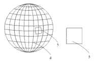
图1是本发明中全景影像采集平台的工作示意图;Fig. 1 is the working schematic diagram of panorama image collection platform among the present invention;
图2是本发明的获取方法流程图;Fig. 2 is the flow chart of acquisition method of the present invention;
图3是本发明的第一实施例中全景影像图片的示意图;FIG. 3 is a schematic diagram of a panoramic video picture in the first embodiment of the present invention;
图4是本发明的第一实施例中球面投影模型的示意图;Fig. 4 is the schematic diagram of spherical projection model in the first embodiment of the present invention;
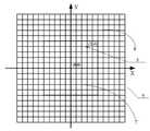
图5是本发明的第一实施例中区域影像图片坐标系的示意图;FIG. 5 is a schematic diagram of a coordinate system of an area image in the first embodiment of the present invention;
图6是本发明的第一实施例中区域影像图片的宽度和长度推导示意图;FIG. 6 is a schematic diagram of deriving the width and length of an area image picture in the first embodiment of the present invention;
图7是本发明的第二实施例中全景影像图片的示意图;FIG. 7 is a schematic diagram of a panoramic video picture in the second embodiment of the present invention;
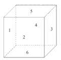
图8是本发明的第二实施例中立方体投影模型的示意图。Fig. 8 is a schematic diagram of a cube projection model in the second embodiment of the present invention.
其中标记:1为第

具体实施方式Detailed ways
本说明书中公开的所有特征,或公开的所有方法或过程中的步骤,除了互相排斥的特征和/或步骤以外,均可以以任何方式组合。All features disclosed in this specification, or steps in all methods or processes disclosed, may be combined in any manner, except for mutually exclusive features and/or steps.
本说明书(包括任何附加权利要求、摘要和附图)中公开的任一特征,除非特别叙述,均可被其他等效或具有类似目的的替代特征加以替换。即,除非特别叙述,每个特征只是一系列等效或类似特征中的一个例子而已。Any feature disclosed in this specification (including any appended claims, abstract and drawings), unless expressly stated otherwise, may be replaced by alternative features which are equivalent or serve a similar purpose. That is, unless expressly stated otherwise, each feature is one example only of a series of equivalent or similar features.
如图1所示,在车载全景影像采集平台的运行过程中间隔地采集全景影像图片,1、2分别表示在第帧和第
本发明中车载全景影像采集平台的航向和俯仰角速度计算不必依赖于陀螺仪或者惯性导航单元等硬件设备,本发明的原理是在车载全景影像采集平台的影像采集过程中,沿着运载车辆行驶方向的较小视野范围内像素点的坐标变化与运载车辆直线运动关系很小,而与运载车辆转向运动关系很大,即该较小视野范围内像素点的坐标变化可以用来表现车载全景影像采集平台的转动情况。In the present invention, the heading and pitch angular velocity calculation of the vehicle-mounted panoramic image acquisition platform does not need to rely on hardware devices such as gyroscopes or inertial navigation units. The coordinate changes of the pixels in the small field of view have little relationship with the linear motion of the vehicle, but have a great relationship with the steering movement of the vehicle, that is, the coordinate changes of the pixels in the small field of view can be used to represent the vehicle panoramic image acquisition The rotation of the platform.
如图2所示,该车载全景影像采集平台的航向和俯仰角速度获取方法由以下步骤组成:As shown in Figure 2, the heading and pitch angular velocity acquisition method of the vehicle-mounted panoramic image acquisition platform consists of the following steps:
S1、车载全景影像采集平台间隔地采集全景影像,构成全景影像图片,其中采集的时间间隔为


S2、采用3D中的纹理映射技术将全景影像图片中的全景影像纹理映射至投影模型上。同样地,当选用球面投影模型时,经纹理映射后的全景影像图片形成球面全景,如图4所示;当选用立方体投影模型时,经纹理映射后的全景影像图片形成立方体全景,如图8所示。S2. Map the panoramic image texture in the panoramic image picture to the projection model by using the texture mapping technology in 3D. Similarly, when the spherical projection model is selected, the panoramic image picture after texture mapping forms a spherical panorama, as shown in Figure 4; when the cubic projection model is selected, the panoramic image picture after texture mapping forms a cubic panorama, as shown in Figure 8 shown.
S3、利用3D技术,在投影模型的中心点设置摄像机,该摄像机正对运载车辆行驶正前方或者正后方,获得水平和垂直视野范围


S4、以上述区域影像图片的中心点为原点建立坐标系统,设定水平向右为X轴正向,垂直向上为Y轴正向,且计算第i帧区域影像图片的原点附近任意像素点(u,v)的特征向量
S5、计算第i+1帧所述区域影像图片的小区域U={(x,y)︱-c≤x-u≤c,-c≤y-v≤c}中所有像素点的特征向量集合 
S6、求取特征向量集合 


S7、根据投影模型单位宽度对应的角度,计算所述车载全景影像采集平台第i+1帧相对于第i帧的航向偏转角度和俯仰偏转角度;S7. According to the angle corresponding to the unit width of the projection model, calculate the heading deflection angle and the pitch deflection angle of the i+1 frame of the vehicle-mounted panoramic image acquisition platform relative to the i frame;
S8、航向偏转角度/


当通过车载全景影像采集平台前进方向获取区域影像图片时,当车载全景影像采集平台向右转向时,航向角速度为正,反之为负;当车载全景影像采集平台上坡时,俯仰角速度为正,反之为负。航向角速度和俯仰角速度的采样率与连续全景影像帧率相同;最小分辨率受全景帧分辨率限制,当

在本发明的第一个实施例中选用球面投影模型作为投影模型,如图3~6所示。图3是车载全景影像采集平台间隔采集到的全景影像图片,其中采集的间隔时间为,且设定该全景影像图片的宽度为


采用3D中的纹理映射技术将全景影像图片中的全景影像纹理映射至球面投影模型上,形成如图4所示的由经纬网格组成的球面全景4。利用3D技术,在3D球体的球心设置摄像机,摄像机沿着运载车辆行驶的正前方或者正后方,获得水平和垂直视野范围内球面上的区域影像5,该区域影像5与运载车辆的直线运动关系无关,利用3D中的渲染到纹理技术将3D球面上的区域影像5渲染到区域影像图片9上,如图5所示,其中区域影像图片的宽度为


如图5所示,区域影像图片中每个交叉点6即表示一个像素点,以该区域影像图片的中心点为原点建立坐标系统,设定水平向右为X轴正向,垂直向上为Y轴正向,针对第i帧的区域影像图片求取坐标系统原点附近任意像素点的特征向量,本实施例中选定以原点(0,0)为中心宽度、高度均为11像素的矩形7,以该矩形的特征向量作为原点(0,0)的特征向量
计算第i+1帧区域影像图片的小区域U={(x,y)︱-c≤x-u≤c,-c≤y-v≤c}中所有像素点的特征向量集合 ,其中x,y均为整数,本实施例中c取30,则小区域即为U={(x,y)︱-30≤x-u≤30,-30≤y-v≤30}。求取特征向量集合 中与特征向量


由于球面投影模型为宽度方向的角度为360度,则单位宽度对应的角度为360/


本实施例中设定相邻帧的时间间隔为63ms,则


在本发明的第二实施例中选用立方体投影模型,如图7~8所示。车载全景影像采集平台采集的全景影像图片如图7所示,由六张大小相同,宽度为
将六张图片分别编号为1-6,采用3D中的纹理映射技术将全景影像图片中的全景影像纹理映射至立方体投影模型上,形成如图8所示的立方体。利用3D技术在立方体的中心设置一个摄像机,摄像机正对运载车辆行驶的正前方或者正后方,获得水平和垂直视野范围


与本发明的第一实施例相同,第二实施例采用相同的方法获得第i+1帧区域影像图片

计算出车载全景影像采集平台第i+1帧相对于第i帧的航向偏转角度、俯仰偏转角度分别为


本实施例中设定相邻帧的时间间隔为63ms,则


除了上述列举出的球面投影模型、立方体投影模型,本发明还可以选用圆柱体投影模型等,根据本发明的总体思路完全可以很容易将此等投影模型用于实际操作中。In addition to the above-listed spherical projection models and cube projection models, the present invention can also use cylindrical projection models, etc. According to the general idea of the present invention, these projection models can be easily used in actual operations.
本发明并不局限于前述的具体实施方式。本发明扩展到任何在本说明书中披露的新特征或任何新的组合,以及披露的任一新的方法或过程的步骤或任何新的组合。The present invention is not limited to the foregoing specific embodiments. The present invention extends to any new feature or any new combination disclosed in this specification, and any new method or process step or any new combination disclosed.
Claims (5)
Translated fromChinese


Priority Applications (1)
| Application Number | Priority Date | Filing Date | Title |
|---|---|---|---|
| CN201110229350.1ACN102426703B (en) | 2011-08-11 | 2011-08-11 | Course and pitch angle speed acquisition method of vehicle panoramic image acquisition platform |
Applications Claiming Priority (1)
| Application Number | Priority Date | Filing Date | Title |
|---|---|---|---|
| CN201110229350.1ACN102426703B (en) | 2011-08-11 | 2011-08-11 | Course and pitch angle speed acquisition method of vehicle panoramic image acquisition platform |
Publications (2)
| Publication Number | Publication Date |
|---|---|
| CN102426703A CN102426703A (en) | 2012-04-25 |
| CN102426703Btrue CN102426703B (en) | 2014-04-09 |
Family
ID=45960682
Family Applications (1)
| Application Number | Title | Priority Date | Filing Date |
|---|---|---|---|
| CN201110229350.1AActiveCN102426703B (en) | 2011-08-11 | 2011-08-11 | Course and pitch angle speed acquisition method of vehicle panoramic image acquisition platform |
Country Status (1)
| Country | Link |
|---|---|
| CN (1) | CN102426703B (en) |
Families Citing this family (4)
| Publication number | Priority date | Publication date | Assignee | Title |
|---|---|---|---|---|
| CN103496339B (en)* | 2013-08-26 | 2015-12-09 | 江西好帮手电子科技有限公司 | A kind of display system by 3D display automobile panorama and its implementation |
| CN106658220B (en)* | 2016-11-11 | 2019-11-19 | 理光图像技术(上海)有限公司 | Subtitle creating device, display module and subtitle create display systems |
| US10097757B1 (en)* | 2017-03-24 | 2018-10-09 | Fotonation Limited | Method for determining bias in an inertial measurement unit of an image acquisition device |
| CN107146274B (en) | 2017-05-05 | 2021-06-22 | 上海兆芯集成电路有限公司 | Image data processing system, texture mapping compression method and method for generating panoramic video |
Family Cites Families (3)
| Publication number | Priority date | Publication date | Assignee | Title |
|---|---|---|---|---|
| CN100458560C (en)* | 2004-12-17 | 2009-02-04 | 上海杰图软件技术有限公司 | Methd for generating spherical panorama based on full frame image |
| JP2006310975A (en)* | 2005-04-26 | 2006-11-09 | Mitsubishi Electric Corp | Video mosaicing device, panoramic video transmission / reception system, panoramic video creation / transmission device, panoramic video reception device, panoramic video strip creation / transmission device, and panoramic video strip reception device |
| CN101938599A (en)* | 2009-06-30 | 2011-01-05 | 爱国者全景(北京)网络科技发展有限公司 | Method for generating interactive dynamic panoramic image |
- 2011
- 2011-08-11CNCN201110229350.1Apatent/CN102426703B/enactiveActive
Also Published As
| Publication number | Publication date |
|---|---|
| CN102426703A (en) | 2012-04-25 |
Similar Documents
| Publication | Publication Date | Title |
|---|---|---|
| CN103761737B (en) | Robot motion's method of estimation based on dense optical flow | |
| CN105627991B (en) | A kind of unmanned plane image real time panoramic joining method and system | |
| CN108534782B (en) | A real-time positioning method of landmark map vehicles based on binocular vision system | |
| CN105352509B (en) | Unmanned plane motion target tracking and localization method under geography information space-time restriction | |
| US9843810B2 (en) | Method of using laser scanned point clouds to create selective compression masks | |
| CN101231456B (en) | Method of Correcting Panoramic Video Jitter Using Angle Sensor | |
| CN103345630B (en) | A kind of traffic signs localization method based on spherical panoramic video | |
| JP6723533B2 (en) | Driving simulator | |
| CN106017463A (en) | Aircraft positioning method based on positioning and sensing device | |
| WO2019084804A1 (en) | Visual odometry and implementation method therefor | |
| CA2395257A1 (en) | Any aspect passive volumetric image processing method | |
| CN105849771A (en) | Simultaneous positioning and mapping on mobile devices | |
| CN106875331B (en) | A kind of asymmetric mapping method of panoramic picture | |
| CN109883433B (en) | Vehicle localization method in structured environment based on 360-degree panoramic view | |
| CN113870367B (en) | Method, apparatus, device, storage medium and program product for generating camera external parameters | |
| CN102426703B (en) | Course and pitch angle speed acquisition method of vehicle panoramic image acquisition platform | |
| CN106303417B (en) | Enhanced panoramic monitoring method for unmanned platform | |
| CN105096284A (en) | Method, device and system of generating road orthographic projection image | |
| TWI444593B (en) | Ground target geolocation system and method | |
| CN113807282B (en) | Data processing method, device and readable storage medium | |
| WO2019119597A1 (en) | Method for implementing planar recording and panoramic recording by coordination between mobile terminal and lens assembly and lens assembly | |
| CN104457758A (en) | Video-acquisition-based Visual Map database establishing method and indoor visual positioning method using database | |
| JP2019533875A (en) | Method and system for generating a composite top view image of a road | |
| CN117629241B (en) | Multi-camera visual inertial odometer optimization method based on continuous time model | |
| JP2019085056A (en) | Environmental change detection method around orbit |
Legal Events
| Date | Code | Title | Description |
|---|---|---|---|
| C06 | Publication | ||
| PB01 | Publication | ||
| C10 | Entry into substantive examination | ||
| SE01 | Entry into force of request for substantive examination | ||
| C14 | Grant of patent or utility model | ||
| GR01 | Patent grant | ||
| TR01 | Transfer of patent right | ||
| TR01 | Transfer of patent right | Effective date of registration:20240328 Address after:6th floor, No. 76 Jianxin North Road, Jiangbei District, Chongqing, 400020 Patentee after:CHONGQING CYBERCITY SCI-TECH Co.,Ltd. Country or region after:China Address before:400020 Jiangbei District, Chongqing electric measuring Village No. 231 Patentee before:CHONGQING SURVEY INSTITUTE Country or region before:China Patentee before:CHONGQING CYBERCITY SCI-TECH Co.,Ltd. |