CN102420373B - Electrical connectors and combinations thereof - Google Patents
Electrical connectors and combinations thereofDownload PDFInfo
- Publication number
- CN102420373B CN102420373BCN201110154007.5ACN201110154007ACN102420373BCN 102420373 BCN102420373 BCN 102420373BCN 201110154007 ACN201110154007 ACN 201110154007ACN 102420373 BCN102420373 BCN 102420373B
- Authority
- CN
- China
- Prior art keywords
- connector
- docking port
- mating
- port
- docking
- Prior art date
- Legal status (The legal status is an assumption and is not a legal conclusion. Google has not performed a legal analysis and makes no representation as to the accuracy of the status listed.)
- Active
Links
Images


Classifications
- H—ELECTRICITY
- H01—ELECTRIC ELEMENTS
- H01R—ELECTRICALLY-CONDUCTIVE CONNECTIONS; STRUCTURAL ASSOCIATIONS OF A PLURALITY OF MUTUALLY-INSULATED ELECTRICAL CONNECTING ELEMENTS; COUPLING DEVICES; CURRENT COLLECTORS
- H01R27/00—Coupling parts adapted for co-operation with two or more dissimilar counterparts
- H01R27/02—Coupling parts adapted for co-operation with two or more dissimilar counterparts for simultaneous co-operation with two or more dissimilar counterparts
- H—ELECTRICITY
- H01—ELECTRIC ELEMENTS
- H01R—ELECTRICALLY-CONDUCTIVE CONNECTIONS; STRUCTURAL ASSOCIATIONS OF A PLURALITY OF MUTUALLY-INSULATED ELECTRICAL CONNECTING ELEMENTS; COUPLING DEVICES; CURRENT COLLECTORS
- H01R13/00—Details of coupling devices of the kinds covered by groups H01R12/70 or H01R24/00 - H01R33/00
- H01R13/46—Bases; Cases
- H01R13/514—Bases; Cases composed as a modular blocks or assembly, i.e. composed of co-operating parts provided with contact members or holding contact members between them
- H—ELECTRICITY
- H01—ELECTRIC ELEMENTS
- H01R—ELECTRICALLY-CONDUCTIVE CONNECTIONS; STRUCTURAL ASSOCIATIONS OF A PLURALITY OF MUTUALLY-INSULATED ELECTRICAL CONNECTING ELEMENTS; COUPLING DEVICES; CURRENT COLLECTORS
- H01R13/00—Details of coupling devices of the kinds covered by groups H01R12/70 or H01R24/00 - H01R33/00
- H01R13/46—Bases; Cases
- H01R13/516—Means for holding or embracing insulating body, e.g. casing, hoods
Landscapes
- Details Of Connecting Devices For Male And Female Coupling (AREA)
Abstract
Description
Translated fromChinese【技术领域】【Technical field】
本发明涉及一种电连接器及其组合,尤指一种具有组合接口的电连接器组合。The invention relates to an electric connector and its combination, especially to an electric connector combination with a combination interface.
【背景技术】【Background technique】
科技的进步带动了信息产业输入输出接口技术的发展,如IEEE1394(火线接口)、HDMI(高清晰度多媒体接口)等新兴接口层出不穷。其中,USB(通用串行总线接口)便是当前规范计算机与外部设备通讯中应用最为普遍的一种接口技术。藉由业界大厂的持续推动及其支持设备即插即用等优势功能,亦逐渐成为键鼠、游戏机、事务机、数字相机等计算机外设设备的主流接口。The advancement of science and technology has driven the development of input and output interface technology in the information industry, such as IEEE1394 (FireWire interface), HDMI (High Definition Multimedia Interface) and other emerging interfaces emerge in endlessly. Among them, USB (Universal Serial Bus Interface) is the most common interface technology used in standardizing the communication between computers and external devices. Thanks to the continuous promotion of major manufacturers in the industry and its advantages such as supporting plug-and-play functions, it has gradually become the mainstream interface for computer peripherals such as keyboards and mice, game consoles, business machines, and digital cameras.
为因应不断增加的数据传输速度及稳定性需求,USB自身亦进行着持续的提升和演进,在经历了USB1.0、USB1.1等多个不同的版本之后,目前市场上广泛应用的是USB2.0版本。与此同时,USB3.0版本正在推进中,其具有高达4.8Gpbs的数据传输速度,同时可以向下兼容现有的USB2.0版本。In response to the ever-increasing data transmission speed and stability requirements, USB itself is also undergoing continuous improvement and evolution. After experiencing many different versions such as USB1.0 and USB1.1, USB2 is currently widely used in the market. .0 version. At the same time, the USB3.0 version is being promoted, which has a data transmission speed of up to 4.8Gpbs, and can be backward compatible with the existing USB2.0 version.
连接器功能在不断强大的同时,介面的复杂度和接插难度也变得越来越大,特别是多个差异化介面在整合的过程中,对准、插入力以及电性连接的稳定性等等都遭遇到不小的挑战。While the functions of connectors are becoming more and more powerful, the complexity of the interface and the difficulty of plugging are also becoming more and more difficult, especially in the process of integrating multiple differentiated interfaces, alignment, insertion force and stability of electrical connection And so on have encountered no small challenges.
因此,需要一种可以解决上述问题的电连接器及其组合。Therefore, there is a need for an electrical connector and its combination that can solve the above problems.
【发明内容】【Content of invention】
发明的目的在于提供一种电连接器,其可提供更方便和稳定的配接。The object of the invention is to provide an electrical connector which can provide more convenient and stable mating.
本发明的目的是通过以下技术方案实现的:一种电连接器组合,其定义有接插方向,所述电连接器组合包括第一电连接器和与第一电连接器配接的第二电连接器,所述第一电连接器包括具有对接舌板的第一连接器对接口以及由金属遮蔽壳体包围的第二连接器对接口,所述第一连接器对接口的对接舌板上和第二连接器对接口内均设有若干导电端子,第一、第二连接器对接口沿纵长方向并列排列,第二连接器对接口的金属遮蔽壳体包围有保护框,第一电连接器在纵长方向的两端分别设有端壁,每一端壁设有向前贯穿的导引槽,其中一导引槽面对对接舌板,另一导引槽面对保护框;所述第二电连接器包括第三连接器对接口和第四连接器对接口,所述第三连接器对接口具有收容第一连接器对接口对接舌板的对接槽,所述第四连接器对接口收容于第二连接器对接口内,第二电连接器在纵长方向的两端分别设有与第一电连接器的导引槽相配合的导引柱,所述第一连接器对接口和第二连接器对接口分别具有最先与第三连接器对接口和第四连接器对接口匹配的配接端缘,所述第二连接器对接口的配接端缘较第一连接器对接口的配接端缘在接插方向上更向前凸伸;所述第三连接器对接口和第四连接器对接口分别具有最先与第一连接器对接口和第二连接器对接口匹配的配接端缘,所述第四连接器对接口的配接端缘较第三连接器对接口的配接端缘在接插方向上更向前凹陷。The object of the present invention is achieved through the following technical solutions: an electrical connector assembly, which defines a plugging direction, and the electrical connector assembly includes a first electrical connector and a second electrical connector mated with the first electrical connector. An electrical connector, the first electrical connector includes a first connector mating port with a mating tongue and a second connector mating port surrounded by a metal shielding shell, the mating tongue of the first connector mating port There are a number of conductive terminals in the upper and second connector mating ports, the first and second connector mating ports are arranged side by side along the longitudinal direction, the metal shielding shell of the second connector mating port is surrounded by a protective frame, and the first The electrical connector is provided with end walls at both ends in the longitudinal direction, and each end wall is provided with a guide groove penetrating forward, one of the guide grooves faces the docking tongue plate, and the other guide groove faces the protective frame; The second electrical connector includes a third connector mating port and a fourth connector mating port, the third connector mating port has a mating groove for accommodating the mating tongue of the first connector mating port, and the fourth connector mating port The connector mating port is accommodated in the second connector mating port, and the two ends of the second electrical connector in the longitudinal direction are respectively provided with guide posts that match the guide grooves of the first electrical connector. The connector mating interface and the second connector mating interface have mating end edges that first match the third connector mating interface and the fourth connector mating interface, respectively, and the mating end edges of the second connector mating interface are smaller than the mating end edges of the first connector mating interface. The mating edge of a connector mating port protrudes forward in the insertion direction; the third connector mating port and the fourth connector mating port respectively have the first connector mating port and the second connector mating port. The mating edge of the mating interface of the connector is matched, and the mating end edge of the mating interface of the fourth connector is more concave forward in the insertion direction than the mating end edge of the mating interface of the third connector.
与现有技术相比,本发明具有以下有益效果:通过向前突出的第一连接器对接口的配接端缘有助于第一电连接器首先对齐,然后整个连接器对齐插入,进而使得两电连接器更容易及更稳定的对接。Compared with the prior art, the present invention has the following beneficial effects: the mating edge of the mating interface of the first connector protruding forward helps the first electrical connector to be aligned first, and then the entire connector is aligned and inserted, thereby making The two electrical connectors are easier and more stable to connect.
【附图说明】【Description of drawings】
图1是电连接器组合的立体图。FIG. 1 is a perspective view of an electrical connector assembly.
图2是第一电连接器跟电路板、支架的立体分解图。FIG. 2 is a three-dimensional exploded view of the first electrical connector, the circuit board, and the bracket.
图3是图2另一角度的立体分解图。Fig. 3 is an exploded perspective view of Fig. 2 from another angle.
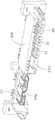
图4是第二电连接器的立体图。Fig. 4 is a perspective view of the second electrical connector.
图5是两连接器的前视图。Fig. 5 is a front view of two connectors.
图6是图3中第一电连接器另一中实施方式的立体图。FIG. 6 is a perspective view of another embodiment of the first electrical connector in FIG. 3 .
【具体实施方式】【Detailed ways】
下面结合图式来详细说明本发明电连接器组合的具体实施方式。The specific implementation manner of the electrical connector combination of the present invention will be described in detail below with reference to the drawings.
请参阅图1所示,所述电连接器组合1000包括安装于可动端的存储设备,比如硬盘的支架5中的第一电连接器100及安装固定端的主板,比如服务器等系统设备端的电路板6上的第二电连接器200。所述电连接器组合1000定义有纵长方向Z、垂直于纵长方向Z的宽度方向X以及垂直于纵长方向Z和宽度方向X的接插方向Y。Please refer to FIG. 1, the
请参阅图1至图3所示,所述第一电连接器100具有一纵长绝缘本体1及位于绝缘本体1中的若干导电端子2,该绝缘本体具有一配接端缘11,导电端子2的焊接部223延伸出绝缘本体相对配接端缘11的后端面。所述第一电连接器100坐落在电路板51设置的缺口511内,导电端子的焊接部223稳定地连接于电路板位于缺口边缘的导电片512,绝缘本体1底面的一对定位柱12则插入电路板6的通孔513内,从而将绝缘本体1固定在电路板51上。然后,支架52向下组装于第一电连接器的顶面。绝缘本体的定位柱13插入支架52的通孔523中,从而将电路板及第一电连接器组装至存储设备中。1 to 3, the first
所述第一电连接器100包括沿纵长方向间隔设置的第一连接器对接口14a和由金属遮蔽壳体16包围的第二连接器对接口14b,来完成电气连接,所述第一连接器对接口14a在纵长方向Z上较第二连接器对接口14b长,所述第二连接器对接口14b较第一连接器对接口14a在接插方向Y上更向前凸伸。第一连接器对接口14a包括一对接舌板15及三组端子21a、21b、21c,其中两组沿纵长方向设置在舌板的第一表面152,另外一组设置在对接舌板的第二表面152。第二连接器对接口14b由金属遮蔽壳体包围若干导电端子22而形成。第一连接器对接口14a适用于电源,第二连接器对接口14b适用于USB3.0Micro B类型,其向后兼容USB2.0Micro B类型。第一电连接器100还包括一保护框17,该保护框跟对接舌板15沿纵长方向并列排列,跟对接舌板15间隔一段距离。第一、二连接器对接口14a、14b沿纵长方向并列排列。The first
所述第一电连接器100的绝缘本体1包括一后壁181、分别位于后壁两端的两端壁182及一侧壁183,该侧壁连接两端壁182,侧壁183位于对接舌板的第一表面侧。保护框17及端壁182均跟对接舌板15间隔开。每一端壁182的内侧设有向前贯穿的导引槽184,其中一导引槽侧向面对对接舌板15,另一导引槽面对保护框。上述端壁、侧壁、对接舌板及保护框均自后壁一体向前延伸形成。侧壁跟舌板平行且间隔一段距离,而侧壁则一体连接于保护框的顶面。The insulating body 1 of the first
所述第一连接器对接口14a的第一组端子21a及第二组端子21b设置在舌板第一表面151的相对两端;而第三组端子21c的数量较多,设置在对接舌板第二表面152的中间部分及靠近端壁的侧。即,第二表面152在靠近保护框17侧的一端具有第一表面积A,该第一表面积与第一表面的第二组端子21b对齐且没有设置任何端子,也就是说对接舌板第二表面上的导电端子设置于远离第二连接器对接口的一端。该舌板的第二表面152可以进一步设置如图6所示,舌板第二表面的在靠近端壁的一端设置有第二表面积B,该第二表面积B跟第一表面的第一组端子21a对齐,且该第二表面积B没有设置任何端子;相对图3而言,其中最左端的3根端子被去处而裸露该第二表面积B。本发明的第一连接器对接口14a类似于习知的SATA电源部分的连接器,跟SATA电源部分的连接器相比较而言,其中位于第一表面积A的3根符合3V电源端子被去除,及位于第二表面积B的3根符合12V电源端子被去除。如此,不但可增强舌板的强度,防止断裂,而且也能兼容SATA电源部分的连接器。舌板的第一表面151在邻近两组端子处还分别进一步设有一固定槽19,来跟第二电连接器配合,达成稳定配合。The first group of terminals 21a and the second group of
请参阅图4所示,所述第二电连接器200属于背板连接器,用来跟第一电连接器100对接。第二电连接器200包括沿纵长方向间隔设置的第三连接器对接口34a和第四连接器对接口34b,所述第三连接器对接口在纵长方向上较第四连接器对接口长,所述第四连接器对接口较第三连接器对接口在接插方向Y上更向前凹陷。第三连接器对接口34a具有一向前贯穿的以收容对接舌板的倒L型对接槽32,及若干裸露于对接槽内的端子41,对接槽由四个侧壁32包围形成。第四连接器对接口34b由金属遮蔽壳体包围形成。对接时,所述第四连接器对接口收容于第二连接器对接口内。Please refer to FIG. 4 , the second
请结合图2并参阅图5所示,每一连接器对接口具有一配接端缘111a、111b、30a、30b,该等配接端缘是指连接器对接时最早接触的点、线或者面。例如,所述第一连接器对接口14a和第二连接器对接口14b分别具有最先与第三连接器对接口34a和第四连接器对接口34b匹配的配接端缘111a,111b,所述第二连接器对接口14b的配接端缘111b较第一连接器对接口14a的配接端缘111a在接插方向Y上更向前凸伸;而所述第三连接器对接口34a和第四连接器对接口34b分别具有最先与第一连接器对接口14a和第二连接器对接口14b匹配的配接端缘30a,30b,所述第四连接器对接口34b的配接端缘30b较第三连接器对接口30a的配接端缘30a在接插方向Y上更向前凹陷。第一连接器对接口的配接端缘111a较第二连接器对接口的配接端缘111b向前延伸,在最佳实施方式中,向前延伸出1.3mm。第三连接器对接口34a的配接端缘30a较第四连接器对接口34b的第四对接面30b向前延伸。所述第三连接器对接口34a在宽度方向X上较第四连接器对接口34b长。Please refer to FIG. 2 and as shown in FIG. 5, each connector mating interface has a
一般的,第一电连接器100位于存储设备端,使用者需要将其插入位于服务器端的第二电连接器200中,向前突出的第一连接器对接口14a的配接端缘111a有助于第一电连接器100首先对齐,然后整个连接器对齐插入,使得两电连接器更容易及更稳定的对接。第二电连接器200的纵长两端凸伸有一对与第一电连接器100的导引槽184相配合的导引柱35,所述导引柱35较第三连接器对接口和第四连接器对接口在接插方向Y上更向前凸伸。而本发明设置长度和宽度上相对较小的对接口提前接触,确保先对准接触小区域,再对准接触大区域,进而使得电连接器组合的配接过程更加地容易和稳定。Generally, the first
综上所述,上述描述的是本发明的较佳实施例,当然并不限于此。即凡是依本发明权利要求书及说明书内容所作的简单的等效变化与修饰,皆应仍属本发明涵盖的范围内。To sum up, what is described above is a preferred embodiment of the present invention, but of course it is not limited thereto. That is, all simple equivalent changes and modifications made according to the claims of the present invention and the content of the description should still fall within the scope of the present invention.
Claims (4)
Applications Claiming Priority (3)
| Application Number | Priority Date | Filing Date | Title |
|---|---|---|---|
| US12/891,825 | 2010-09-28 | ||
| US12/891825 | 2010-09-28 | ||
| US12/891,825US8210874B2 (en) | 2010-09-28 | 2010-09-28 | Combo electrical connector |
Publications (2)
| Publication Number | Publication Date |
|---|---|
| CN102420373A CN102420373A (en) | 2012-04-18 |
| CN102420373Btrue CN102420373B (en) | 2014-02-19 |
Family
ID=45871100
Family Applications (1)
| Application Number | Title | Priority Date | Filing Date |
|---|---|---|---|
| CN201110154007.5AActiveCN102420373B (en) | 2010-09-28 | 2011-06-09 | Electrical connectors and combinations thereof |
Country Status (3)
| Country | Link |
|---|---|
| US (1) | US8210874B2 (en) |
| CN (1) | CN102420373B (en) |
| TW (1) | TWI477000B (en) |
Families Citing this family (9)
| Publication number | Priority date | Publication date | Assignee | Title |
|---|---|---|---|---|
| TWM438739U (en)* | 2012-04-13 | 2012-10-01 | Tyco Electronics Holdings Bermuda No 7 Ltd | Connector with a guide portion |
| TWI574466B (en)* | 2012-04-16 | 2017-03-11 | 鴻海精密工業股份有限公司 | Electrical connector |
| CN103378469B (en)* | 2012-04-17 | 2017-01-25 | 富士康(昆山)电脑接插件有限公司 | Electric connector |
| CN104332759A (en)* | 2014-11-12 | 2015-02-04 | 成都缤果科技有限公司 | Positioning mechanism for USB (Universal Serial Bus) connection |
| USD807865S1 (en)* | 2015-08-07 | 2018-01-16 | Airgain Incorporated | Antenna mounting frame |
| CN105511569B (en)* | 2015-11-30 | 2019-01-18 | 英业达科技有限公司 | server |
| CN111799603A (en)* | 2020-06-09 | 2020-10-20 | 东莞市鼎通精密科技股份有限公司 | Communication connector in staggered connection |
| TWI798625B (en)* | 2021-01-20 | 2023-04-11 | 佳必琪國際股份有限公司 | Electric-connecting module and power integration structure of connecting interface thereof |
| TWI807835B (en)* | 2022-05-20 | 2023-07-01 | 台灣莫仕股份有限公司 | socket connector |
Citations (6)
| Publication number | Priority date | Publication date | Assignee | Title |
|---|---|---|---|---|
| US5067915A (en)* | 1984-10-23 | 1991-11-26 | Siemens Aktiengesellschaft | Plug-in component |
| US5667401A (en)* | 1994-05-31 | 1997-09-16 | Fujitsu Limited | Cable connector, circuit board and system having circuit boards connected together by the cable connector |
| US6069992A (en)* | 1996-11-05 | 2000-05-30 | Itt Manufacturing Enterprises, Inc. | Connector system with precision alignment |
| CN2415500Y (en)* | 2000-01-20 | 2001-01-17 | 富士康(昆山)电脑接插件有限公司 | socket connector |
| CN1992447A (en)* | 2005-12-29 | 2007-07-04 | 富士康(昆山)电脑接插件有限公司 | Electrical connector assembly |
| CN101673903A (en)* | 2008-09-09 | 2010-03-17 | 富士康(昆山)电脑接插件有限公司 | Electric connector and electric connector assembly |
Family Cites Families (5)
| Publication number | Priority date | Publication date | Assignee | Title |
|---|---|---|---|---|
| USD469407S1 (en)* | 2002-04-02 | 2003-01-28 | Hon Hai Precision Ind. Co., Ltd. | Electrical connector |
| US6908330B2 (en)* | 2002-11-15 | 2005-06-21 | Western Digital Technologies, Inc. | Storage peripheral having a robust serial advanced technology attachment (SATA) PCB connector |
| US6832934B1 (en)* | 2004-03-18 | 2004-12-21 | Hon Hai Precision Ind. Co., Ltd | High speed electrical connector |
| US6887098B1 (en)* | 2004-05-17 | 2005-05-03 | Cheng Uei Precision Industry Co., Ltd. | Combined electrical connector |
| US7497709B1 (en)* | 2007-09-12 | 2009-03-03 | Hon Hai Precision Ind. Co., Ltd. | Electrical connector with switch device |
- 2010
- 2010-09-28USUS12/891,825patent/US8210874B2/ennot_activeExpired - Fee Related
- 2011
- 2011-06-09CNCN201110154007.5Apatent/CN102420373B/enactiveActive
- 2011-07-11TWTW100124388Apatent/TWI477000B/enactive
Patent Citations (6)
| Publication number | Priority date | Publication date | Assignee | Title |
|---|---|---|---|---|
| US5067915A (en)* | 1984-10-23 | 1991-11-26 | Siemens Aktiengesellschaft | Plug-in component |
| US5667401A (en)* | 1994-05-31 | 1997-09-16 | Fujitsu Limited | Cable connector, circuit board and system having circuit boards connected together by the cable connector |
| US6069992A (en)* | 1996-11-05 | 2000-05-30 | Itt Manufacturing Enterprises, Inc. | Connector system with precision alignment |
| CN2415500Y (en)* | 2000-01-20 | 2001-01-17 | 富士康(昆山)电脑接插件有限公司 | socket connector |
| CN1992447A (en)* | 2005-12-29 | 2007-07-04 | 富士康(昆山)电脑接插件有限公司 | Electrical connector assembly |
| CN101673903A (en)* | 2008-09-09 | 2010-03-17 | 富士康(昆山)电脑接插件有限公司 | Electric connector and electric connector assembly |
Also Published As
| Publication number | Publication date |
|---|---|
| TWI477000B (en) | 2015-03-11 |
| CN102420373A (en) | 2012-04-18 |
| US20120077379A1 (en) | 2012-03-29 |
| US8210874B2 (en) | 2012-07-03 |
| TW201223009A (en) | 2012-06-01 |
Similar Documents
| Publication | Publication Date | Title |
|---|---|---|
| CN102420373B (en) | Electrical connectors and combinations thereof | |
| CN102324656B (en) | Electrical connector and combination thereof | |
| CN102195223B (en) | Electrical connector and complex thereof | |
| US7559805B1 (en) | Electrical connector with power contacts | |
| CN201029182Y (en) | Cable Connector Assembly | |
| US7467977B1 (en) | Electrical connector with additional mating port | |
| US8864506B2 (en) | Cable connector with improved grounding plate | |
| CN201113076Y (en) | socket electrical connector | |
| US7618293B2 (en) | Extension to electrical connector with improved housing structures | |
| CN101364692B (en) | Electric connector for socket | |
| US7736184B1 (en) | Receptacle connector | |
| US7803009B2 (en) | Plug connector with improved cable arrangement and convenient assembly | |
| US8920197B2 (en) | Connector receptacle with ground contact having split rear extensions | |
| CN201097426Y (en) | socket electrical connector | |
| CN2687869Y (en) | Electric connector | |
| CN105024195A (en) | Straddle mount connector and pluggable transceiver module having the same | |
| CN201860011U (en) | All-in-one connector | |
| CN100466392C (en) | Electrical Connector Assembly | |
| CN201113078Y (en) | electrical connector | |
| CN103972670A (en) | Cable connector subassembly | |
| CN101924303A (en) | socket electrical connector | |
| CN203596429U (en) | Electric connector for coupling first circuit board and second circuit board | |
| CN106785532B (en) | Composite connector | |
| CN201656181U (en) | Conductive contact structure of connector | |
| CN2318731Y (en) | Electric connection switching device |
Legal Events
| Date | Code | Title | Description |
|---|---|---|---|
| C06 | Publication | ||
| PB01 | Publication | ||
| C10 | Entry into substantive examination | ||
| SE01 | Entry into force of request for substantive examination | ||
| C14 | Grant of patent or utility model | ||
| GR01 | Patent grant |