CN102419261B - Automobile wheel positioner TDOF (three degrees of freedom) calibrating system with extended wide-area visual field space - Google Patents
Automobile wheel positioner TDOF (three degrees of freedom) calibrating system with extended wide-area visual field spaceDownload PDFInfo
- Publication number
- CN102419261B CN102419261BCN 201110232285CN201110232285ACN102419261BCN 102419261 BCN102419261 BCN 102419261BCN 201110232285CN201110232285CN 201110232285CN 201110232285 ACN201110232285 ACN 201110232285ACN 102419261 BCN102419261 BCN 102419261B
- Authority
- CN
- China
- Prior art keywords
- plate
- processed
- holes
- threaded
- workbench
- Prior art date
- Legal status (The legal status is an assumption and is not a legal conclusion. Google has not performed a legal analysis and makes no representation as to the accuracy of the status listed.)
- Expired - Fee Related
Links
- 230000000007visual effectEffects0.000titleclaimsabstractdescription4
- 238000006073displacement reactionMethods0.000claimsabstractdescription24
- 229910000831SteelInorganic materials0.000claimsdescription40
- 239000010959steelSubstances0.000claimsdescription40
- 238000001514detection methodMethods0.000abstractdescription9
- 238000009434installationMethods0.000description5
- 238000005259measurementMethods0.000description5
- 238000000034methodMethods0.000description5
- 238000004519manufacturing processMethods0.000description4
- 238000007689inspectionMethods0.000description2
- 238000003754machiningMethods0.000description2
- 230000009286beneficial effectEffects0.000description1
- 230000003247decreasing effectEffects0.000description1
- 239000000446fuelSubstances0.000description1
- 230000007774longtermEffects0.000description1
Images


Landscapes
- Length Measuring Devices With Unspecified Measuring Means (AREA)
Abstract
Translated fromChinese
Description
Translated fromChinese技术领域technical field
本发明涉及一种汽车工业领域的标定设备,更具体的说,它涉及一种在广域视场空间延拓的汽车车轮定位仪三自由度标定系统。The invention relates to a calibration device in the field of the automobile industry, more specifically, it relates to a three-degree-of-freedom calibration system for an automobile wheel aligner extended in a wide field of view space.
背景技术Background technique
为保证汽车的操纵稳定性,汽车的车轮、转向节和车轴三者之间的安装具有一定的相对位置,称为车轮定位。汽车车轮参数是否准确,对汽车的行驶安全性、操纵稳定性和燃油经济性具有重要影响。车轮定位仪是检验车辆安全性的重要的检测设备。目前全国仅车轮定位仪的保有量就达30000多台,并且以每年30%的速度在递增。In order to ensure the handling stability of the car, the installation between the wheels, steering knuckle and axle shaft of the car has a certain relative position, which is called wheel alignment. Whether the vehicle wheel parameters are accurate or not has an important impact on the driving safety, handling stability and fuel economy of the vehicle. The wheel aligner is an important testing device for checking the safety of the vehicle. At present, there are more than 30,000 wheel aligners in the country alone, and the number is increasing at an annual rate of 30%.
立体视觉测量车轮定位参数可以实现非接触检测,视觉系统检测前需要进行标定,现有车轮定位参数立体视觉检测系统的标定均采用二维或三维标定板,在由标定板的尺寸所确定的空间内标定精度较高,在标定板空间之外系统的标定精度无法得到保证。在进行车轮定位参数检测时,由于汽车的轴距和轮距通常在1.5米到3米之间,无法加工与该尺寸相同的大型标定板并保证标定板各特征点的相对位置尺寸。Stereo vision measurement of wheel alignment parameters can realize non-contact detection, and the vision system needs to be calibrated before detection. The calibration of existing wheel alignment parameter stereo vision detection systems uses two-dimensional or three-dimensional calibration plates. The space determined by the size of the calibration plate The internal calibration accuracy is high, and the calibration accuracy of the system outside the calibration board space cannot be guaranteed. When detecting wheel alignment parameters, since the wheelbase and wheelbase of the car are usually between 1.5 meters and 3 meters, it is impossible to process a large calibration plate of the same size and ensure the relative position and size of each feature point on the calibration plate.
目前,国内外尚未发现相关的报道。At present, no relevant reports have been found at home and abroad.
发明内容Contents of the invention
本发明采用纵向、横向导轨及回转工作台的结构,使标定板实现了在汽车轴距和轮距确定的空间内任意位置和角度的移动,并通过传感器计量标定板在各运动位置时,标定板上的特征点相对于初始世界坐标系原点的世界坐标,实现了将小标定板在广域视场空间延拓的目的。系统具有体积较小、标定板位置及角度可调整、操作简便、性能可靠、通用性强、易于安装、制造成本低、精度高等特点,提供了一种可以满足国家计量、质量监督部门以及生产厂家标定要求的在广域视场空间延拓的汽车车轮定位仪三自由度标定系统。The invention adopts the structure of longitudinal and transverse guide rails and a rotary workbench, so that the calibration plate can move at any position and angle in the space determined by the wheelbase and wheelbase of the automobile, and when the calibration plate is in each moving position, the calibration plate can be calibrated by the sensor. The world coordinates of the feature points on the board relative to the origin of the initial world coordinate system realize the purpose of extending the small calibration board in the wide field of view space. The system has the characteristics of small size, adjustable position and angle of the calibration plate, easy operation, reliable performance, strong versatility, easy installation, low manufacturing cost and high precision. A three-degree-of-freedom calibration system for automobile wheel aligners extended in a wide field of view space required for calibration.
参阅图1至图9,为解决上述技术问题,本发明采用如下技术方案予以实现。本发明所提供的在广域视场空间延拓的汽车车轮定位仪三自由度标定系统包括有底板、纵向导轨、滑块、横向连接板、横向导轨、标定板、拉线位移传感器、传感器安装架、工作台连接座、标定板连接座与工作台。Referring to Fig. 1 to Fig. 9, in order to solve the above-mentioned technical problems, the present invention adopts the following technical solutions to realize. The three-degree-of-freedom calibration system of the automobile wheel alignment instrument provided by the present invention, which extends in the space of the wide field of view, includes a base plate, a longitudinal guide rail, a slider, a transverse connecting plate, a transverse guide rail, a calibration plate, a cable displacement sensor, and a sensor mounting frame , Workbench connection seat, calibration plate connection seat and workbench.
螺栓自上而下分别穿过两个相同的纵向导轨的T型通孔和底板的两排螺纹孔,将纵向导轨与底板螺纹固定连接,每个纵向导轨与两个滑块底部的凹槽滑动配合,螺栓自上而下分别穿过两个横向导轨的T型通孔和横向连接板中部的螺纹孔,将横向导轨与横向连接板螺纹固定连接,横向导轨与纵向导轨垂直,螺栓自下而上分别穿过与纵向导轨滑动配合的滑块的T型通孔和横向连接板底部的螺纹孔,将四个滑块与横向连接板螺纹固定连接,每个横向导轨与两个滑块底部的凹槽滑动配合,螺栓自下而上分别穿过与横向导轨滑动配合的滑块的T型通孔和工作台连接座底部的螺纹孔,将横向导轨上的四个滑块与工作台连接座螺纹固定连接。The bolts pass through the T-shaped through holes of two identical longitudinal guide rails and the two rows of threaded holes in the base plate from top to bottom, and the longitudinal guide rails are screwed to the base plate, and each longitudinal guide rail slides with the grooves at the bottom of the two sliders. Cooperate, the bolts pass through the T-shaped through holes of the two transverse guide rails and the threaded hole in the middle of the transverse connecting plate from top to bottom, and the transverse guide rail and the transverse connecting plate are screwed and fixedly connected. Through the T-shaped through hole of the slider that is slidingly matched with the longitudinal guide rail and the threaded hole at the bottom of the transverse connecting plate, the four sliders are screwed to the transverse connecting plate, and each transverse guide rail is connected to the bottom of the two sliders. The groove is slidingly fitted, and the bolts pass through the T-shaped through hole of the slider that is slidingly matched with the horizontal guide rail and the threaded hole at the bottom of the workbench connecting seat from bottom to top, and connect the four sliders on the transverse guide rail to the workbench connecting seat Screw fixed connection.
两个螺栓自上而下穿过工作台底部侧面的两个半圆通孔和工作台连接座顶部加工的两个螺纹孔,将工作台与工作台连接座螺纹固定连接,螺栓插入工作台顶面的T型槽后穿过标定板连接座下端的螺纹通孔,通过螺母将标定板连接座与工作台固定连接,螺栓自下而上穿过标定板连接座上端的圆形通孔和标定板底部的螺纹盲孔,将标定板与标定板连接座螺纹固定连接。Two bolts pass through the two semicircular through holes on the bottom side of the workbench and the two threaded holes processed on the top of the workbench connection seat from top to bottom, and the workbench and the workbench connection seat are screwed and fixedly connected, and the bolts are inserted into the top surface of the workbench After passing through the threaded hole at the lower end of the connecting seat of the calibration plate, the connecting seat of the calibration plate is fixedly connected with the workbench through nuts, and the bolts pass through the circular through hole at the upper end of the connecting seat of the calibration plate and the calibration plate from bottom to top The threaded blind hole at the bottom securely connects the calibration plate with the calibration plate connecting seat.
螺栓自上而下穿过传感器安装架水平面的四个圆形通孔和底板沿钢板较长方向的一端加工的四个螺纹孔,将一个传感器安装架与底板螺纹固定连接,两个螺栓穿过传感器安装架垂直面的两个圆形通孔与一个拉线位移传感器底部的螺纹盲孔螺纹固定连接,拉线位移传感器的拉线端部的螺杆与横向连接板侧面加工的螺纹孔螺纹固定连接,螺栓自上而下穿过传感器安装架水平面的四个圆形通孔和横向连接板顶面沿钢板较长方向的一端加工的四个螺纹孔,将一个传感器安装架与横向连接板螺纹固定连接,两个螺栓穿过传感器安装架垂直面的两个圆形通孔与一个拉线位移传感器底部的螺纹盲孔螺纹固定连接,拉线位移传感器的拉线端部的螺杆与工作台连接座侧面加工的螺纹孔螺纹固定连接。The bolts pass through the four circular through holes on the horizontal plane of the sensor mounting frame from top to bottom and the four threaded holes processed on one end of the bottom plate along the longer direction of the steel plate, and a sensor mounting frame is fixedly connected with the bottom plate with threads, and two bolts pass through The two circular through holes on the vertical surface of the sensor mounting frame are fixedly connected with the threaded blind hole at the bottom of a cable displacement sensor. The four circular through holes passing through the horizontal plane of the sensor mounting frame from top to bottom and the four threaded holes processed on the top surface of the transverse connecting plate along the long direction of the steel plate are fixedly connected with one sensor mounting frame and the transverse connecting plate by screws. Two bolts pass through the two circular through holes on the vertical surface of the sensor mounting frame and are fixedly connected with the threaded blind hole at the bottom of a pull wire displacement sensor. Fixed connection.
技术方案中所述的底板为一矩形钢板,沿钢板较长方向加工有两排螺纹孔,沿钢板较长方向的一端加工有四个螺纹孔。The bottom plate described in the technical solution is a rectangular steel plate, two rows of threaded holes are processed along the long direction of the steel plate, and four threaded holes are processed along one end of the long direction of the steel plate.
技术方案中所述的横向连接板为一矩形钢板,顶面沿钢板较长方向加工有两排螺纹孔,顶面沿钢板较长方向的一端加工有四个螺纹孔,底面两端分别加工有八个螺纹孔,侧面加工有一个螺纹孔。The transverse connecting plate described in the technical proposal is a rectangular steel plate, two rows of threaded holes are processed on the top surface along the longer direction of the steel plate, four threaded holes are processed on one end of the top surface along the longer direction of the steel plate, and two rows of threaded holes are processed on the two ends of the bottom surface respectively. Eight threaded holes, one threaded hole machined on the side.
技术方案中所述的工作台连接座为长方体零件,工作台连接座底部加工有螺纹孔,顶部加工有两个螺纹孔,侧面加工有一个螺纹孔。The workbench connecting seat described in the technical solution is a cuboid part, the bottom of the workbench connecting seat is processed with threaded holes, the top is processed with two threaded holes, and the side is processed with a threaded hole.
技术方案中所述的标定板连接座为两端粗、中部细的阶梯圆柱型零件,下端加工有均布螺纹孔,上端加工有均布圆形通孔。The connecting seat of the calibration plate described in the technical proposal is a stepped cylindrical part with thick ends and a thin middle part. The lower end is processed with uniformly distributed threaded holes, and the upper end is processed with uniformly distributed circular through holes.
技术方案中所述的标定板为三块矩形钢板垂直焊接的零件,底部加工有螺纹盲孔。The calibration plate described in the technical proposal is a vertically welded part of three rectangular steel plates, and the bottom is processed with threaded blind holes.
技术方案中所述的传感器安装架为L型钢板,L型钢板的水平面加工有四个圆形通孔,垂直面加工两个圆形通孔。The sensor mounting frame described in the technical proposal is an L-shaped steel plate, four circular through holes are processed on the horizontal plane of the L-shaped steel plate, and two circular through holes are processed on the vertical plane.
本发明的有益效果是:The beneficial effects of the present invention are:
(1)本发明采用纵向、横向导轨及回转工作台的结构,使标定板实现了在汽车轴距和轮距确定的空间内任意位置和角度的移动,并通过传感器计量标定板在各运动位置时,标定板上的特征点相对于初始世界坐标系原点的世界坐标,实现了将小标定板在广域视场空间延拓的目的,解决了由于标定板过小导致的在标定板所确定的空间之外视觉系统测量精度下降的问题,对机器视觉检测领域的技术进步具有重要意义。(1) The present invention adopts the structure of longitudinal and transverse guide rails and a rotary table, so that the calibration plate can move at any position and angle in the space determined by the wheelbase and wheelbase of the automobile, and the calibration plate can be measured at each moving position by the sensor. When the feature points on the calibration board are relative to the world coordinates of the origin of the initial world coordinate system, the purpose of extending the small calibration board in the wide field of view space is realized, and the problem caused by the calibration board being too small is solved. The problem of the decrease of the measurement accuracy of the vision system outside the space is of great significance to the technological progress in the field of machine vision inspection.
(2)本发明的部分零件采用标准钢材进行加工,首先,标准钢材产量大,机械加工工序少,生产成本较低;其次,作为测量仪器的重要附件,采用标准钢材具有一定的强度,能够在长期使用中不变形,保证测量的精度,可以满足国家标准对检测精度的要求;最后,部分零件为钢材组成的空心结构,大大降低了检测设备的重量,提高了设备安装调整操作的灵活性。(2) part parts of the present invention adopt standard steel to process, at first, the output of standard steel is big, and machining process is few, and production cost is lower; Secondly, as the important accessory of measuring instrument, adopt standard steel to have certain strength, can It does not deform during long-term use, ensures the accuracy of measurement, and can meet the requirements of national standards for detection accuracy; finally, some parts are hollow structures composed of steel, which greatly reduces the weight of the detection equipment and improves the flexibility of equipment installation and adjustment operations.
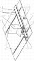
图1是在广域视场空间延拓的汽车车轮定位仪三自由度标定系统的轴测图;Figure 1 is an axonometric view of a three-degree-of-freedom calibration system for a vehicle wheel aligner extended in a wide field of view space;
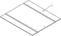
图2是底板1的轴测图;Fig. 2 is the axonometric view of
图3是横向连接板4的轴测图;Fig. 3 is the axonometric view of transverse connecting
图4是底板1、纵向导轨2、滑块3、横向连接板4、横向导轨5、拉线位移传感器7、传感器安装架8、工作台连接座9、标定板连接座10和工作台11连接位置的局部轴测图;Figure 4 shows the connection positions of the
图5是标定板6的轴测图;Fig. 5 is the axonometric view of calibration plate 6;
图6是传感器安装架8的轴测图;Fig. 6 is an axonometric view of the
图7是拉线位移传感器7和传感器安装座8的轴测图;Fig. 7 is an axonometric view of the stay
图8是工作台连接座9的轴测图;Fig. 8 is an axonometric view of the
图9是标定板连接座10的轴测图;Fig. 9 is an axonometric view of the calibration
图中:1.底板,2.纵向导轨,3.滑块,4.横向连接板,5.横向导轨,6.标定板,7.拉线位移传感器,8.传感器安装架,9.工作台连接座,10.标定板连接座,11.工作台。In the figure: 1. Bottom plate, 2. Longitudinal guide rail, 3. Slider, 4. Transverse connecting plate, 5. Transverse guide rail, 6. Calibration plate, 7. Pull wire displacement sensor, 8. Sensor mounting frame, 9. Workbench connection Seat, 10. Calibration board connection seat, 11. Workbench.
具体实施方式Detailed ways
下面结合附图对本发明作进一步的详细描述:Below in conjunction with accompanying drawing, the present invention will be described in further detail:
本发明采用纵向、横向导轨及回转工作台的结构,使标定板实现了在汽车轴距和轮距确定的空间内任意位置和角度的移动,并通过传感器计量标定板在各运动位置时,标定板上的特征点相对于初始世界坐标系原点的世界坐标,实现了将小标定板在广域视场空间延拓的目的。系统具有体积较小、标定板位置及角度可调整、操作简便、性能可靠、通用性强、易于安装、制造成本低、精度高等特点,提供了一种可以满足国家计量、质量监督部门以及生产厂家标定要求的在广域视场空间延拓的汽车车轮定位仪三自由度标定系统。The invention adopts the structure of longitudinal and transverse guide rails and a rotary workbench, so that the calibration plate can move at any position and angle in the space determined by the wheelbase and wheelbase of the automobile, and when the calibration plate is in each moving position, the calibration plate can be calibrated by the sensor. The world coordinates of the feature points on the board relative to the origin of the initial world coordinate system realize the purpose of extending the small calibration board in the wide field of view space. The system has the characteristics of small size, adjustable position and angle of the calibration plate, easy operation, reliable performance, strong versatility, easy installation, low manufacturing cost and high precision. A three-degree-of-freedom calibration system for automobile wheel aligners extended in a wide field of view space required for calibration.
本发明采用纵向、横向导轨及回转工作台的结构,使标定板实现了在汽车轴距和轮距确定的空间内任意位置和角度的移动,并通过传感器计量标定板在各运动位置时,标定板上的特征点相对于初始世界坐标系原点的世界坐标,实现了将小标定板在广域视场空间延拓的目的,解决了由于标定板过小导致的在标定板所确定的空间之外视觉系统测量精度下降的问题,对机器视觉检测领域的技术进步具有重要意义。The invention adopts the structure of longitudinal and transverse guide rails and a rotary workbench, so that the calibration plate can move at any position and angle in the space determined by the wheelbase and wheelbase of the automobile, and when the calibration plate is in each moving position, the calibration plate can be calibrated by the sensor. The feature points on the board are relative to the world coordinates of the origin of the initial world coordinate system, which realizes the purpose of extending the small calibration board in the wide field of view space, and solves the gap between the space determined by the calibration board due to the small calibration board. The problem of decreased measurement accuracy of the external vision system is of great significance to the technological progress in the field of machine vision inspection.
本发明的部分零件采用标准钢材进行加工,首先,标准钢材产量大,机械加工工序少,生产成本较低;其次,作为测量仪器的重要附件,采用标准钢材具有一定的强度,能够在长期使用中不变形,保证测量的精度,可以满足国家标准对检测精度的要求;最后,部分零件为钢材组成的空心结构,大大降低了检测设备的重量,提高了设备安装调整操作的灵活性。Some parts of the present invention are processed by standard steel. Firstly, the output of standard steel is large, the machining process is less, and the production cost is low; secondly, as an important accessory of the measuring instrument, the standard steel has a certain strength and can be It does not deform, ensures the accuracy of measurement, and can meet the requirements of national standards for detection accuracy; finally, some parts are hollow structures composed of steel, which greatly reduces the weight of the detection equipment and improves the flexibility of equipment installation and adjustment operations.
参阅图1至图9,在广域视场空间延拓的汽车车轮定位仪三自由度标定系统包括有底板1、纵向导轨2、滑块3、横向连接板4、横向导轨5、标定板6、拉线位移传感器7、传感器安装架8、工作台连接座9、标定板连接座10与工作台11。Referring to Fig. 1 to Fig. 9, the three-degree-of-freedom calibration system of the automobile wheel aligner extended in the wide field of view space includes a
底板1为一矩形钢板,沿钢板较长方向加工有两排螺纹孔,沿钢板较长方向的一端加工有四个螺纹孔,螺栓自上而下分别穿过两个相同的纵向导轨2的T型通孔和底板1的两排螺纹孔,将纵向导轨2与底板1螺纹固定连接,每个纵向导轨2与两个滑块3底部的凹槽滑动配合。The
横向连接板4为一矩形钢板,顶面沿钢板较长方向加工有两排螺纹孔,顶面沿钢板较长方向的一端加工有四个螺纹孔,底面两端分别加工有八个螺纹孔,侧面加工有一个螺纹孔,用于连接拉线位移传感器7,螺栓自上而下分别穿过两个横向导轨5的T型通孔和横向连接板4中部的螺纹孔,将横向导轨5与横向连接板4螺纹固定连接,横向导轨5与纵向导轨2垂直,螺栓自下而上分别穿过与纵向导轨2滑动配合的滑块3的T型通孔和横向连接板4底部的螺纹孔,将四个滑块3与横向连接板4螺纹固定连接,每个横向导轨5与两个滑块3底部的凹槽滑动配合。The transverse connecting
螺栓自下而上分别穿过与横向导轨5滑动配合的滑块3的T型通孔和工作台连接座9底部的螺纹孔,将横向导轨5上的四个滑块3与工作台连接座9螺纹固定连接。The bolts pass through the T-shaped through hole of the
工作台连接座9为长方体零件,工作台连接座9底部加工有螺纹孔,用于连接滑块3,顶部加工有两个螺纹孔,侧面加工有一个螺纹孔,用于连接拉线位移传感器7,两个螺栓自上而下穿过工作台11底部侧面的两个半圆通孔和工作台连接座9顶部加工的两个螺纹孔,将工作台11与工作台连接座9螺纹固定连接。The
标定板连接座10为两端粗、中部细的阶梯圆柱型零件,下端加工有均布螺纹孔,上端加工有均布圆形通孔,螺栓插入工作台11顶面的T型槽后穿过标定板连接座10下端的螺纹通孔,通过螺母将标定板连接座10与工作台11固定连接,螺栓自下而上穿过标定板连接座10上端的圆形通孔和标定板6底部的螺纹盲孔,将标定板6与标定板连接座10螺纹固定连接。The connecting
标定板6为三块矩形钢板垂直焊接的零件,底部加工有螺纹盲孔。The calibration plate 6 is a vertically welded part of three rectangular steel plates, and the bottom is processed with threaded blind holes.
传感器安装架8为L型钢板,L型钢板的水平面加工有四个圆形通孔,垂直面加工两个圆形通孔,螺栓自上而下穿过传感器安装架8水平面的四个圆形通孔和底板1沿钢板较长方向的一端加工的四个螺纹孔,将一个传感器安装架8与底板1螺纹固定连接,两个螺栓穿过传感器安装架8垂直面的两个圆形通孔与一个拉线位移传感器7底部的螺纹盲孔螺纹固定连接,拉线位移传感器7的拉线端部的螺杆与横向连接板4侧面加工的螺纹孔螺纹固定连接,螺栓自上而下穿过传感器安装架8水平面的四个圆形通孔和横向连接板4顶面沿钢板较长方向的一端加工的四个螺纹孔,将一个传感器安装架8与横向连接板4螺纹固定连接,两个螺栓穿过传感器安装架8垂直面的两个圆形通孔与一个拉线位移传感器7底部的螺纹盲孔螺纹固定连接,拉线位移传感器7的拉线端部的螺杆与工作台连接座9侧面加工的螺纹孔螺纹固定连接。The
在广域视场空间延拓的汽车车轮定位仪三自由度标定系统的使用方法:The method of using the three-degree-of-freedom calibration system of the automobile wheel aligner extended in the wide field of view space:
设标定板6的初始位置为世界坐标系的原点,移动横向连接板4,使横向连接板4在纵向导轨2上移动一定距离,从拉线位移传感器7上读出位移量Δx,然后移动工作台连接座9,使工作台连接座9在横向导轨上移动一定距离,从拉线位移传感器7上读出位移量Δy,最后调整工作台11带动标定板6绕垂直轴旋转一定角度,从工作台11的手轮刻度中读出旋转角度Δθ,则经过调整后的位置为(Δx,Δy,Δθ)。经过三次调整,可以得到标定板6在运动后新位置的世界坐标,因此该方法相当于将标定板6上的特征坐标点在x,y和θ方向分别延拓了Δx、Δy、Δθ,通过摄像机采集标定板6在不同位置的多幅图像可以利用标定板已知的位移量Δx、Δy、Δθ,建立更广阔范围的标准标定点,达到视觉系统的标定物在广域视场空间延拓的目的,可实现采用小标定板在汽车轴距和轮距所确定的较大视场空间范围的视觉系统标定,实现视觉式汽车车轮定位仪的精确检测。Set the initial position of the calibration plate 6 as the origin of the world coordinate system, move the transverse connecting
Claims (6)
Translated fromChinesePriority Applications (1)
| Application Number | Priority Date | Filing Date | Title |
|---|---|---|---|
| CN 201110232285CN102419261B (en) | 2011-08-15 | 2011-08-15 | Automobile wheel positioner TDOF (three degrees of freedom) calibrating system with extended wide-area visual field space |
Applications Claiming Priority (1)
| Application Number | Priority Date | Filing Date | Title |
|---|---|---|---|
| CN 201110232285CN102419261B (en) | 2011-08-15 | 2011-08-15 | Automobile wheel positioner TDOF (three degrees of freedom) calibrating system with extended wide-area visual field space |
Publications (2)
| Publication Number | Publication Date |
|---|---|
| CN102419261A CN102419261A (en) | 2012-04-18 |
| CN102419261Btrue CN102419261B (en) | 2013-11-06 |
Family
ID=45943776
Family Applications (1)
| Application Number | Title | Priority Date | Filing Date |
|---|---|---|---|
| CN 201110232285Expired - Fee RelatedCN102419261B (en) | 2011-08-15 | 2011-08-15 | Automobile wheel positioner TDOF (three degrees of freedom) calibrating system with extended wide-area visual field space |
Country Status (1)
| Country | Link |
|---|---|
| CN (1) | CN102419261B (en) |
Families Citing this family (8)
| Publication number | Priority date | Publication date | Assignee | Title |
|---|---|---|---|---|
| CN103292700B (en)* | 2013-05-28 | 2015-07-15 | 吉林大学 | Space general position and orientation measurement standard of machine vision measurement system |
| CN104359688B (en)* | 2014-12-02 | 2016-08-31 | 吉林大学 | The T-shaped displacement overall situation verification system of vehicle wheel alignment parameter vision detection system |
| CN108981603A (en)* | 2018-05-29 | 2018-12-11 | 北京零壹空间科技有限公司 | Scaling method and device for spatial digitizer |
| CN111307033B (en)* | 2018-12-12 | 2022-01-18 | 成都蒸汽巨人机器人科技有限公司 | Industrial robot depth vision sensor calibration board and calibration method |
| CN109548538A (en)* | 2018-12-31 | 2019-04-02 | 杭州珑亚珀伟科技有限公司 | Apple fast bagging system and method |
| CN109566212B (en)* | 2018-12-31 | 2021-04-02 | 杭州珑亚珀伟科技有限公司 | Automatic apple bagging device and method |
| CN111192330A (en)* | 2020-03-13 | 2020-05-22 | 北京石头世纪科技股份有限公司 | Binocular camera calibration tool |
| CN112762819A (en)* | 2020-12-02 | 2021-05-07 | 北京机械工业自动化研究所有限公司 | Detection device and measurement method for precision detection of visual sensor |
Family Cites Families (4)
| Publication number | Priority date | Publication date | Assignee | Title |
|---|---|---|---|---|
| JP4931867B2 (en)* | 2008-06-27 | 2012-05-16 | 黒田精工株式会社 | Variable terminal |
| CN100575865C (en)* | 2008-07-18 | 2009-12-30 | 西安交通大学 | Spatial localization method based on dual rotating laser planar transmitter network |
| CN101691995B (en)* | 2009-10-14 | 2011-10-26 | 吉林大学 | Stereovision-based method and stereovision-based device for detecting vehicle wheelbase difference |
| CN202177517U (en)* | 2011-08-15 | 2012-03-28 | 吉林大学 | Automobile wheel position indicator three-freedom-degree calibrating system extending in wide view field space |
- 2011
- 2011-08-15CNCN 201110232285patent/CN102419261B/ennot_activeExpired - Fee Related
Also Published As
| Publication number | Publication date |
|---|---|
| CN102419261A (en) | 2012-04-18 |
Similar Documents
| Publication | Publication Date | Title |
|---|---|---|
| CN102419261B (en) | Automobile wheel positioner TDOF (three degrees of freedom) calibrating system with extended wide-area visual field space | |
| CN102322797B (en) | Three-degree-of-freedom vehicle wheel alignment parameters stereo vision flexible detection system | |
| CN202177517U (en) | Automobile wheel position indicator three-freedom-degree calibrating system extending in wide view field space | |
| CN102175417B (en) | Spatial positioning test rack for use in tunnel body of wind tunnel | |
| CN105526885B (en) | A kind of taper hole cone angle high-precision detecting method based on composite probe | |
| CN103292700B (en) | Space general position and orientation measurement standard of machine vision measurement system | |
| CN102607502A (en) | Automatic detection device and method for size of automobile rear axle assembly | |
| CN202229727U (en) | Three freedom-degree vehicle wheel alignment parameter stereoscopic vision flexible detection system | |
| CN102661700A (en) | Detection apparatus of long stroke leading screw installation precision and application method thereof | |
| CN102788550A (en) | Comprehensive visualization measuring instrument of multi-sensor shape and position errors | |
| CN103592139B (en) | Based on the multiaxis commercial vehicle wheel alignment parameter vision measurement system of two-dimensional target | |
| CN102679877B (en) | Calibration system for commercial vehicle vision measurement based on longitude and altitude spatial positioning principle | |
| CN203405335U (en) | An installing clamp suitable for real-time wheel detection | |
| CN202420360U (en) | Automobile tail light support measurement checking tool | |
| CN105115465B (en) | A kind of measuring method and device of cycloid gear flank profil normal error | |
| CN103100974A (en) | Honing machine detecting system | |
| CN203069163U (en) | Displacement sensor clamping device for steering frame parameter testing | |
| CN203249590U (en) | General space position and attitude measurement benchmark of machine vision measurement system | |
| CN110567387B (en) | Continuous measuring instrument for channel steel/I-steel machining hole site | |
| CN105423952B (en) | The mechanical distortion factor measuring instrument of automobile shape measurement system | |
| CN204202884U (en) | The T-shaped displacement overall situation verification system of vehicle wheel alignment parameter vision detection system | |
| CN204988148U (en) | Measuring tool of FSAE cycle racing wheel and frame orientation angle | |
| CN210400313U (en) | Channel steel/I-steel processing hole site continuous measurement appearance | |
| CN202547959U (en) | Hexastyle stereoscopic vision detection system for automobile wheel positioning parameters | |
| CN202403668U (en) | Detachable positioning device for column type dashboard skeleton of automobile |
Legal Events
| Date | Code | Title | Description |
|---|---|---|---|
| C06 | Publication | ||
| PB01 | Publication | ||
| C10 | Entry into substantive examination | ||
| SE01 | Entry into force of request for substantive examination | ||
| C14 | Grant of patent or utility model | ||
| GR01 | Patent grant | ||
| CF01 | Termination of patent right due to non-payment of annual fee | Granted publication date:20131106 Termination date:20150815 | |
| EXPY | Termination of patent right or utility model |