CN102402133B - Double-workpiece-platform same-phase rotation exchange method based on parallel connection mechanisms, and device thereof - Google Patents
Double-workpiece-platform same-phase rotation exchange method based on parallel connection mechanisms, and device thereofDownload PDFInfo
- Publication number
- CN102402133B CN102402133BCN 201110377373CN201110377373ACN102402133BCN 102402133 BCN102402133 BCN 102402133BCN 201110377373CN201110377373CN 201110377373CN 201110377373 ACN201110377373 ACN 201110377373ACN 102402133 BCN102402133 BCN 102402133B
- Authority
- CN
- China
- Prior art keywords
- workpiece
- rotary
- workpiece table
- linear motor
- parallel
- Prior art date
- Legal status (The legal status is an assumption and is not a legal conclusion. Google has not performed a legal analysis and makes no representation as to the accuracy of the status listed.)
- Expired - Fee Related
Links
- 238000000034methodMethods0.000titleclaimsabstractdescription56
- 230000007246mechanismEffects0.000titleclaimsabstractdescription39
- 238000012546transferMethods0.000claimsabstractdescription55
- 230000008569processEffects0.000claimsabstractdescription33
- 230000033001locomotionEffects0.000claimsdescription52
- 230000003068static effectEffects0.000claimsdescription30
- 238000006243chemical reactionMethods0.000claimsdescription16
- 238000003032molecular dockingMethods0.000claimsdescription9
- 238000007667floatingMethods0.000claimsdescription7
- 238000000926separation methodMethods0.000claimsdescription5
- 230000005540biological transmissionEffects0.000claimsdescription3
- 230000009977dual effectEffects0.000claims1
- 238000001179sorption measurementMethods0.000claims1
- 238000001459lithographyMethods0.000abstractdescription19
- 238000005516engineering processMethods0.000abstractdescription9
- 238000004519manufacturing processMethods0.000abstractdescription8
- 238000004804windingMethods0.000abstractdescription4
- 238000004904shorteningMethods0.000abstractdescription3
- 239000004065semiconductorSubstances0.000abstractdescription2
- 230000008859changeEffects0.000description22
- 230000008901benefitEffects0.000description8
- 238000012545processingMethods0.000description4
- 235000012431wafersNutrition0.000description4
- XUIMIQQOPSSXEZ-UHFFFAOYSA-NSiliconChemical compound[Si]XUIMIQQOPSSXEZ-UHFFFAOYSA-N0.000description3
- 230000001133accelerationEffects0.000description3
- 238000011161developmentMethods0.000description3
- 238000010586diagramMethods0.000description3
- 238000007781pre-processingMethods0.000description3
- 229910052710siliconInorganic materials0.000description3
- 239000010703siliconSubstances0.000description3
- 230000020169heat generationEffects0.000description2
- 230000003287optical effectEffects0.000description2
- 230000033764rhythmic processEffects0.000description2
- 230000017105transpositionEffects0.000description2
- 229910000831SteelInorganic materials0.000description1
- 230000002411adverseEffects0.000description1
- 230000009286beneficial effectEffects0.000description1
- 230000008878couplingEffects0.000description1
- 238000010168coupling processMethods0.000description1
- 238000005859coupling reactionMethods0.000description1
- 230000007812deficiencyEffects0.000description1
- 238000009826distributionMethods0.000description1
- 230000000694effectsEffects0.000description1
- 230000006872improvementEffects0.000description1
- 210000001503jointAnatomy0.000description1
- 238000012423maintenanceMethods0.000description1
- 238000005259measurementMethods0.000description1
- 238000011160researchMethods0.000description1
- 239000010959steelSubstances0.000description1
- 230000007704transitionEffects0.000description1
Images


Landscapes
- Exposure And Positioning Against Photoresist Photosensitive Materials (AREA)
- Container, Conveyance, Adherence, Positioning, Of Wafer (AREA)
Abstract
Translated fromChineseDescription
Translated fromChinese技术领域technical field
本发明属于半导体制造装备技术领域,主要涉及基于并联机构的双工件台同相位回转交换方法与装置。 The invention belongs to the technical field of semiconductor manufacturing equipment, and mainly relates to a method and device for in-phase rotation and exchange of double workpiece tables based on a parallel mechanism. the
背景技术Background technique
光刻机是极大规模集成电路制造中重要的超精密装备之一。光刻机的分辨率和套刻精度决定了集成电路芯片的最小线宽,同时光刻机的产率则极大的影响集成电路芯片的生产成本,而作为光刻机关键子系统的工件台又在很大程度上决定了光刻机的分辨率、套刻精度和产率。 Lithography machine is one of the important ultra-precision equipment in the manufacture of very large scale integrated circuits. The resolution and engraving accuracy of the lithography machine determine the minimum line width of the integrated circuit chip. At the same time, the yield of the lithography machine greatly affects the production cost of the integrated circuit chip. As the key subsystem of the lithography machine, the workpiece table It also determines the resolution, overlay accuracy and productivity of the lithography machine to a large extent. the
产率是光刻机发展的主要追求目标之一。在满足分辨率和套刻精度的条件下,提高工件台运行效率进而提高光刻机产率是工件台技术的发展方向。提高工件台运行效率最直接的方式就是提高工件台的运动加速度和速度,但是为保证原有精度,速度和加速度不能无限制提高。最初的工件台只有一个硅片承载装置,光刻机一次只能处理一个硅片,全部工序串行处理,生产效率低。为此有人提出了双工件台技术,这也是目前提高光刻机生产效率的主流技术手段。双工件台技术在工件台上设有曝光工位,预处理工位两个工位和两个工件台,曝光和测量调整可并行处理,大大缩短了时间,提高了生产效率。目前的代表产品为荷兰ASML公司基于TwinScan技术即双工件台技术的光刻机。 Productivity is one of the main goals of lithography machine development. Under the condition of satisfying the resolution and overlay accuracy, improving the operating efficiency of the workpiece table and thus improving the productivity of the lithography machine is the development direction of the workpiece table technology. The most direct way to improve the operating efficiency of the workpiece table is to increase the motion acceleration and speed of the workpiece table, but in order to ensure the original accuracy, the speed and acceleration cannot be increased without limit. The initial workpiece table only had one silicon wafer carrier, and the lithography machine could only process one silicon wafer at a time. All processes were processed serially, and the production efficiency was low. For this reason, someone has proposed a double worktable technology, which is also the mainstream technical means to improve the production efficiency of lithography machines. The double worktable technology has an exposure station on the worktable, two pretreatment stations and two worktables. The exposure and measurement adjustment can be processed in parallel, which greatly shortens the time and improves the production efficiency. The current representative product is the lithography machine based on the TwinScan technology, that is, the double-workpiece technology of the Dutch ASML company. the
提高双工件台的运行效率是目前光刻机工件台技术的发展目标之一。双工件台技术牵涉到工件台在两个工位之间切换的问题,换台效率直接影响双工件台的运行效率以及光刻机的产率。如何在尽可能缩短换台时间的条件下减小换台对其它系统的干扰一直是研究的重点。在传统双台切换过程中,工件台与曝光和预处理工序中一样为直线驱动。双台专利US2001/0004105A1和 WO98/40791中,每个工件台有两个可交换配合的单元来实现双台的交换,在不提高工件台运动速度的前提下提高了产率,但由于工件台与导轨之间也采用耦合连接方式,在换台过程中工件台与驱动单元会出现短暂的分离,对工件台的定位精度产生较大影响。同时运动单元和导轨较长,运动质量较大,对于运动速度和加速度的提高都产生不良影响。专利CN101231471A中,采用H型驱动单元与过渡承接装置上的摩擦轮对接,以避免导轨对接精度问题,但是工件台在换台时需要等待驱动单元与摩擦轮完成对接后才可进行换台操作,对产率带来很大影响。专利CN1828427A中,在预处理工位设置了一个X向导轨,曝光工位设置有两个X向导轨,实现两个工位的并行工作,但由于驱动单元固定在基座上,在工件台运动时会有较大力传递到基座上,对整体带来不良影响。 Improving the operating efficiency of the double workpiece table is one of the development goals of the current lithography machine workpiece table technology. The double worktable technology involves the problem of switching the worktable between two stations, and the efficiency of changing the worktable directly affects the operating efficiency of the double worktable and the productivity of the lithography machine. How to reduce the interference of channel switching to other systems while shortening the channel switching time as much as possible has always been the focus of research. In the traditional double-stage switching process, the workpiece stage is linearly driven as in the exposure and pretreatment process. In the double-table patents US2001/0004105A1 and WO98/40791, each workpiece table has two interchangeable and coordinated units to realize the exchange of double tables, which improves the productivity without increasing the moving speed of the workpiece table. However, due to the The coupling connection with the guide rail is also used, and the workpiece table and the drive unit will be separated temporarily during the table change process, which will have a great impact on the positioning accuracy of the workpiece table. At the same time, the motion unit and the guide rail are longer, and the motion mass is larger, which has adverse effects on the improvement of the motion speed and acceleration. In the patent CN101231471A, the H-type drive unit is used to dock with the friction wheel on the transition receiving device to avoid the problem of the butt joint accuracy of the guide rail. However, when the workpiece table is changed, it is necessary to wait for the drive unit to complete the docking with the friction wheel before performing the table change operation. have a great impact on productivity. In the patent CN1828427A, one X-guiding rail is set at the pretreatment station, and two X-guiding rails are provided at the exposure station to realize the parallel work of the two stations. However, since the drive unit is fixed on the base, the workpiece table moves Occasionally, a greater force will be transmitted to the base, which will have a bad influence on the whole. the
上述方案中,换台时都没有考虑换台时导向装置的运动对效率的影响。从换台节拍上考虑都采用五节拍形式,即在换台过程中,两个工件台需要停留一段时间使得抓卡装置完成交换,从而完成换台工作。在对光刻机产率要求越来越高的情况下,抓卡装置的交换时间也会对产率产生很大的影响。专利CN101201555中,利用传送带和对接滑块完成换台过程,运动节拍少,操作维护简单,但传送带机构和对接滑块固定在基台上,因此在换台过程中,会有较大的力作用在基台上,对整体动态性能影响较大。专利CN1485694中,利用Y向直线电机和直线导轨的对接完成换台操作,但由于基台中间的间隙过大而引入桥接装置,使得运动节拍增加,增加了换台时间,同时X向直线电机磁钢部分固定在基台上,换台时运动部件的运动会对基台产生较大的反作用力,进而影响整个系统的动态性能。专利CN101770181中利用置换单元的对接完成换台工作,但其导向装置固定在基台上,在换台运动中,运动部件会对基台产生较大的反作用力,进而影响整个系统的动态性能。因此目前的双台直线换台方案 有待改进。 In the above solutions, the influence of the movement of the guide device on the efficiency during the channel change is not taken into account. In terms of the beat of the table change, the form of five beats is adopted, that is, in the process of changing the table, the two workpiece tables need to stay for a period of time so that the card grabbing device can complete the exchange, thereby completing the work of changing the table. In the case of higher and higher requirements on the productivity of lithography machines, the replacement time of the card grabbing device will also have a great impact on the productivity. In the patent CN101201555, the conveyor belt and the docking slider are used to complete the stage changing process, the movement rhythm is small, and the operation and maintenance are simple. However, the conveyor belt mechanism and the docking slider are fixed on the abutment, so there will be a large force during the stage changing process On the abutment, it has a great influence on the overall dynamic performance. In the patent CN1485694, the table-changing operation is completed by the docking of the Y-direction linear motor and the linear guide rail. However, due to the excessive gap in the middle of the abutment, a bridging device is introduced, which increases the movement rhythm and increases the time for table-changing. At the same time, the X-direction linear motor magnetically The steel part is fixed on the abutment, and the movement of the moving parts will generate a large reaction force on the abutment when changing the stage, which in turn affects the dynamic performance of the entire system. In the patent CN101770181, the docking of the replacement unit is used to complete the table changing work, but its guide device is fixed on the abutment. During the table changing movement, the moving parts will generate a large reaction force on the abutment, which in turn affects the dynamic performance of the entire system. Therefore, the current two-stage straight-line exchange program needs to be improved. the
回转换台方案较直线换台方案有独特优势,因此出现了采用回转方式换台的双工件台技术。例如欧洲专利WO98/28665采用带传动实现工件台上曝光工位和预处理工位的两个工件台交换位置,简化了换台工序,但是带传动难以实现纳米定位精度。专利CN101071275采用回转整个基台的方式实现双工件台的换位,简化了系统结构,同时两个工件台运动无重叠区域,避免了碰撞安全隐患。但是通过回转整个基台实现工件台换位存在转动惯量大,大功率回转电机精密定位困难和发热量大引起系统温升等问题,同时回转半径大,使光刻机主机结构显著增大。专利CN102141739采用旋转电机完成硅片台工位的交换,避免了大惯量的基台旋转,省去要求极高的导轨对接装置和辅助装置,但是该系统换台过程中造成了工件台上传感器和对准标记的相位反转,从而难以实现同位相的双工件台交换。上述方案均没有考虑回转换台方式下工件台相位反转与光学系统难以配合的问题。在光刻机曝光和预处理工序中,光学系统需要对工件台各位置传感器和对准标记进行检测,由于各位置传感器和对准标记分布不均,各对准标记结构原理不一致,工件台存在朝向问题。当回转换台后,工件台回转180°造成工件台位置传感器和对准标记反向,因此目前回转换台方案还有待改进。此外回转换台方式的回转特性造成工件台线缆缠绕以及激光干涉仪反射镜回转导致目标丢失等问题还有待解决。 Compared with the straight-line table-changing scheme, the rotary table-changing scheme has unique advantages, so the double-workpiece table technology that adopts the rotary method for table-changing has emerged. For example, the European patent WO98/28665 uses a belt drive to exchange positions between the exposure station and the pretreatment station on the work table, which simplifies the stage change process, but it is difficult to achieve nanometer positioning accuracy with the belt drive. Patent CN101071275 adopts the method of rotating the whole abutment to realize the transposition of the double workpiece table, which simplifies the system structure, and at the same time, the movement of the two workpiece tables has no overlapping area, avoiding the potential safety hazard of collision. However, there are problems such as large moment of inertia, difficulty in precise positioning of high-power rotary motors, and high heat generation that cause system temperature rise by rotating the entire base to achieve workpiece table transposition. At the same time, the radius of rotation is large, which significantly increases the main structure of the lithography machine. The patent CN102141739 uses a rotary motor to complete the exchange of the wafer stage station, which avoids the rotation of the base stage with large inertia, and saves the extremely demanding guide rail docking device and auxiliary device. The phases of the alignment marks are reversed, making it difficult to exchange double work stages with the same phase. None of the above-mentioned solutions considers the problem that the phase inversion of the workpiece table and the optical system are difficult to cooperate in the way of returning to the conversion table. In the exposure and pretreatment process of the lithography machine, the optical system needs to detect the position sensors and alignment marks of the workpiece table. Due to the uneven distribution of the position sensors and alignment marks, the structural principles of each alignment mark are inconsistent, and the workpiece table has towards the problem. When the transfer table is turned back, the workpiece table rotates 180°, causing the position sensor of the workpiece table and the alignment mark to be reversed, so the current plan of returning the transfer table still needs to be improved. In addition, the rotary characteristics of the rotary table method cause the cable winding of the workpiece table and the target loss due to the rotation of the laser interferometer mirror has yet to be solved. the
发明内容Contents of the invention
本发明针对上述已有技术中存在的不足,设计提供一种基于并联机构的双工件台同相位回转交换方法与装置。此装置采用回转方式进行双台切换,降低了双台切换时间,提高了换台效率和光刻机的产率。同时解决了工件台相位反转,工件台线缆缠绕以及激光干涉仪目标丢失等问题。本发明解决了现有线性 换台方案冲击转矩大和换台节拍多的问题,采用较小的质量平衡系统,有利于缩短平衡时间,同时简化系统,降低成本,换台节拍减少缩短了换台时间,有效提高了光刻机产率。 The present invention aims at the deficiencies in the above-mentioned prior art, and designs and provides a method and device for in-phase rotation and exchange of double workpiece tables based on a parallel mechanism. This device adopts a rotary method to switch between two sets, which reduces the time for switching between two sets, improves the efficiency of switching between sets and the productivity of the lithography machine. At the same time, it solves the problems of phase inversion of the workpiece table, cable winding of the workpiece table, and loss of the target of the laser interferometer. The present invention solves the problems of large impact torque and many beats in the existing linear channel change scheme, adopts a smaller mass balance system, which is beneficial to shorten the balance time, simplifies the system at the same time, reduces costs, reduces the cycle time of channel change and shortens the change of channel time, effectively improving the productivity of the lithography machine. the
本发明的目的是这样实现的: The purpose of the present invention is achieved like this:
基于并联机构的双工件台同相位回转交换方法,该方法由三个节拍组成,第一个节拍是:第一工件台完成曝光工序、第二工件台完成预处理工序后,分别从曝光工位和预处理工位向基台中心运动,回转换台抓卡装置通过电磁吸附第一工件台的第一工件台回转环套和第二工件台的第二工件台回转环套,同时,X向第一直线电机动子和X向第二直线电机动子上的抓卡机构分别松开第一工件台的第一工件台转接装置和第二工件台的第二工件台转接装置,同时,第一防转杆和第二防转杆伸长,并抓卡住第一工件台,第三防转杆和第四防转杆伸长,并抓卡住第二工件台,实现两工件台与回转转接台相向对接;第二节拍是:回转转接台吸附住第一工件台和第二工件台绕基台中心轴线沿顺时针或逆时针回转180°(下一次回转交换沿逆时针或顺时针),同时第一并联杆和第二并联杆随第一工件台和Y向第一静压气浮导轨的距离远近而自动伸缩,防止第一工件台在换台过程中回转运动带来的相位变化;同时第三并联杆和第四并联杆随第二工件台和Y向第二静压气浮导轨的距离远近而自动伸缩,防止第二工件台在换台过程中回转运动带来的相位变化,实现第一工件台和第二工件台在整个回转换台传动过程中的同相位;第三个节拍是:回转转接台回转180°后,回转换台抓卡装置放开第一工件台的第一工件台回转环套和第二工件台的第二工件台回转环套;同时X向第一直线电机动子上的抓卡机构抓卡住第二工件台的第二工件台转接装置,并运动到曝光工位,X向第二直线电机动子上的抓卡机构抓卡住第一工件台的第一工件台转接装置,并运动到预处理工位,实现两工件 台与回转转接台反向分离并到各自工位;通过上述三个节拍完成双工件台同相位回转交换。 Based on the parallel mechanism, the double-workpiece stage rotation exchange method in the same phase is composed of three beats. The first beat is: after the first worktable completes the exposure process and the second workbench completes the pretreatment process, respectively from the exposure work The station and the pretreatment station move to the center of the abutment, and the clamping device of the rotary conversion table electromagnetically absorbs the first workpiece table rotary ring sleeve of the first workpiece table and the second workpiece table rotary ring sleeve of the second workpiece table. At the same time, X Loosen the first workpiece table adapter device of the first workpiece table and the second workpiece table adapter device of the second workpiece table respectively to the gripping mechanism on the first linear motor mover and the X-direction second linear motor mover , at the same time, the first anti-rotation rod and the second anti-rotation rod are elongated, and grasp the first workpiece table, the third anti-rotation rod and the fourth anti-rotation rod are extended, and grasp the second workpiece table, realizing The two workpiece tables are oppositely docked with the rotary transfer table; the second beat is: the rotary transfer table absorbs the first workpiece table and the second workpiece table and rotates 180° clockwise or counterclockwise around the central axis of the abutment (the next rotary exchange Counterclockwise or clockwise), at the same time, the first parallel rod and the second parallel rod automatically expand and contract with the distance between the first workpiece table and the first static pressure air bearing guide rail in the Y direction, so as to prevent the first workpiece table from changing stages The phase change caused by the rotary motion; at the same time, the third parallel rod and the fourth parallel rod automatically expand and contract with the distance between the second workpiece table and the second static pressure air bearing guide rail in the Y direction, preventing the second workpiece table from changing stages The phase change brought about by the rotary motion realizes the same phase between the first workpiece table and the second workpiece table during the entire transmission process of the rotary transfer table; the third beat is: after the rotary transfer table rotates 180°, the rotary transfer table grabs the card The device releases the first workpiece table rotary ring sleeve of the first workpiece table and the second workpiece table rotary ring sleeve of the second workpiece table; at the same time, the clamping mechanism on the X-direction first linear motor mover grabs the second workpiece The second worktable transfer device of the first worktable, and move to the exposure station, the grabbing mechanism on the X-direction second linear motor mover grabs the first worktable transfer device of the first worktable, and moves to the preset position The processing station realizes the reverse separation of the two workpiece tables from the rotary transfer table and goes to their respective stations; the same-phase rotary exchange of the two workpiece tables is completed through the above three beats. the
基于并联机构的双工件台同相位回转交换装置包括基台、第一工件台、第二工件台,基台长边Y方向两端为曝光工位和预处理工位,第一工件台和第二工件台分别运行于曝光工位和预处理工位,沿基台长边两侧对应分别设置由Y向第一直线电机、Y向第一静压气浮导轨和由Y向第二直线电机、Y向第二静压气浮导轨构成的两个Y向长行程直线运动单元,曝光工位上设置有由X向第一直线电机动子、X向第一直线电机定子、X向第一静压气浮导轨以及第一承载梁构成的X向第一长行程直线运动单元,预处理工位上设置有由X向第二直线电机动子、X向第二直线电机定子、X向第二静压气浮导轨以及第二承载梁构成的X向第二长行程直线运动单元,在基台四周装有激光干涉仪;第一工件台和第二工件台分别配装在X向第一长行程直线运动单元和X向第二长行程直线运动单元上,X向第一长行程直线运动单元和X向第二长行程直线运动单元分别与Y向长行程直线运动单元成H型配置;在基台上位于曝光工位和预处理工位之间部位处配装一个回转转接台,回转转接台包括回转电机定子、回转电机动子和回转换台抓卡装置,其中回转电机定子固装在基台下侧部上,回转电机动子可转动地配装在回转电机定子上,在回转电机动子上端部上固装回转换台抓卡装置;在第一工件台中部设置第一工件台回转环套,在第一工件台底部X向侧面设置第一工件台转接装置;在第二工件台中部设置第二工件台回转环套,在第二工件台底部X向侧面设置第二工件台转接装置;在Y向第一静压气浮导轨和第一工件台之间连接设置由两个长度可伸缩的第一并联杆和第二并联杆组成的第一并联防转机构,在Y向第二静压气浮导轨和第二工件台之间连接设置由两个长度可伸缩的第三并联杆和第四并联杆组成的第二并联防转机构;第一 工件台和第二工件台底面为气浮面,且第一工件台和第二工件台气浮在基台之上;第一工件台回转环套与第一工件台的接触环面为静压气浮轴承,回转换台时套与台做相对回转运动;第二工件台回转环套与第二工件台的接触面为气浮环面,回转换台时套与台做相对回转运动;在运行过程中,激光干涉仪发出的光束始终与第一工件台、第二工件台对应的侧面反射镜垂直;Y向第一直线电机、Y向第二直线电机、X向第一直线电机动子、X向第一直线电机定子、X向第二直线电机动子、X向第二直线电机定子采用平板电机,或采用U型槽式电机。 The same-phase rotary exchange device for double workpiece tables based on a parallel mechanism includes a base, a first workpiece, and a second workpiece. The two ends of the long side of the base in the Y direction are the exposure station and the pretreatment station. The first workpiece and the The second workpiece table runs on the exposure station and the pretreatment station respectively. The first linear motor from the Y direction, the first static pressure air bearing guide rail from the Y direction and the second Two Y-direction long-stroke linear motion units composed of linear motors and Y-direction second static pressure air bearing guide rails. The exposure station is equipped with X-direction first linear motor movers, X-direction first linear motor stators, The X-direction first long-stroke linear motion unit composed of the X-direction first static pressure air bearing guide rail and the first load beam. The pre-processing station is equipped with an X-direction second linear motor mover and an X-direction second linear motor stator. , the second X-direction static pressure air bearing guide rail and the second X-direction long-stroke linear motion unit composed of the second load beam, and a laser interferometer is installed around the base; the first workpiece table and the second workpiece table are respectively equipped on On the X-direction first long-stroke linear motion unit and the X-direction second long-stroke linear motion unit, the X-direction first long-stroke linear motion unit and the X-direction second long-stroke linear motion unit are respectively formed with the Y-direction long-stroke linear motion unit H-type configuration; a rotary transfer table is installed on the base between the exposure station and the pretreatment station. The rotary transfer table includes a rotary motor stator, a rotary motor mover and a rotary transfer table grabbing device. Among them, the stator of the rotary motor is fixedly installed on the lower side of the abutment, the mover of the rotary motor is rotatably fitted on the stator of the rotary motor, and the upper end of the mover of the rotary motor is fixedly installed back to the clamping device of the conversion table; Set the first workpiece table rotary ring sleeve in the middle of the table, and install the first workpiece table transfer device on the X-direction side of the bottom of the first workpiece table; set the second workpiece table rotary ring sleeve in the middle of the second workpiece table, The second workpiece table transfer device is arranged on the side of the X direction; the second parallel rod composed of two stretchable lengths of the first parallel rod and the second parallel rod is connected between the first static pressure air bearing guide rail and the first workpiece table in the Y direction. A parallel anti-rotation mechanism, a second parallel anti-rotation mechanism composed of two telescopic third parallel rods and fourth parallel rods is connected between the Y-direction second static pressure air bearing guide rail and the second workpiece table; The bottom surfaces of the first workpiece platform and the second workpiece platform are air-floating surfaces, and the first workpiece platform and the second workpiece platform are air-floated on the base platform; the contact ring surface of the first workpiece platform rotary ring sleeve and the first workpiece platform is static Compressed air bearing, the sleeve and the table make relative rotary motion when turning the transfer table; the contact surface between the rotary ring sleeve of the second workpiece table and the second workpiece table is an air-floating ring surface, and the sleeve and the table make relative rotary motion when the transfer table is turned; During operation, the beam emitted by the laser interferometer is always perpendicular to the side reflectors corresponding to the first workpiece table and the second workpiece table; Y to the first linear motor, Y to the second linear motor, X to the first linear motor The motor mover, the X-direction first linear motor stator, the X-direction second linear motor mover, and the X-direction second linear motor stator adopt flat motors or U-shaped slot motors. the
本发明具有以下创新点和突出优点: The present invention has the following innovations and outstanding advantages:
1.提出基于并联机构的双工件台同相位回转交换方法。采用该方法换台仅需三个节拍,即第一节拍是两工件台沿轴线(Z轴O-O)与回转转接台相向对接;第二节拍是回转转接台携两工件台绕回转轴线沿顺时针或逆时针方向回转180°(下一次转位沿逆时针或顺时针方向回转180°);第三节拍是两工件台与回转转接台反向分离并到各自工位。该方法解决了现有线性换台方法节拍过多(五个节拍)的问题,同时解决了回转换台传感器和标记板相位反转、整体转动平台方式转动惯量大、换台时间长等问题。与现有方法与装置相比,本方法和装置实现了双工件台换台过程同相位保持,并缩短了换台时间,显著提高换台效率和光刻机的产片率,这是本发明的创新点和突出优点之一。 1. Propose a method for the same-phase rotation exchange of double workpiece tables based on the parallel mechanism. Using this method, only three beats are needed to change the table, that is, the first beat is that the two workpiece tables are oppositely docked with the rotary transfer table along the axis (Z axis O-O); the second beat is that the rotary transfer table carries the two workpiece tables along the axis of rotation. Rotate 180° clockwise or counterclockwise (the next indexing will rotate 180° counterclockwise or clockwise); the third beat is that the two workpiece tables are separated from the rotary transfer table in reverse and go to their respective stations. The method solves the problem of too many beats (five beats) in the existing linear channel changing method, and at the same time solves the problems of the phase inversion of the sensor and the marking plate of the return conversion table, the large moment of inertia of the overall rotating platform mode, and the long time for channel changing. Compared with the existing method and device, the method and device realize the same phase during the process of changing the double workpiece stage, shorten the time for changing the stage, and significantly improve the efficiency of changing the stage and the film production rate of the lithography machine. One of the innovative points and outstanding advantages of the invention. the
2.提出基于并联机构的双工件台同相位回转交换装置。两工件台在随回转转接台绕轴线(Z轴O-O)回转180°的过程中,两工件台通过各自对应的并联机构控制自转运动,始终保持两工件台在零位时的相位不变,保证双工件台在换台过程中的同相位。解决了现有回转换台方式存在的三大问题,即工件台相位反相、工件台线缆缠绕和激光干涉仪目标丢失等问题。确保在换台过程中工 件台相位始终不变,线缆不缠绕和激光干涉仪目标连续跟踪,这是本发明的创新点和突出优点之二。 2. Propose a double-workpiece rotary exchange device with the same phase based on the parallel mechanism. During the 180° rotation of the two workpiece tables around the axis (Z axis O-O) with the rotary transfer table, the two workpiece tables control the self-rotation movement through their corresponding parallel mechanisms, and keep the phase of the two workpiece tables at the zero position. Ensure the same phase of the double workpiece table during the table changing process. It solves the three major problems existing in the existing conversion table method, that is, the phase reversal of the workpiece table, the winding of the cable of the workpiece table, and the loss of the target of the laser interferometer. It is the second innovation point and outstanding advantage of the present invention to ensure that the phase of the workpiece stage remains unchanged during the stage change process, the cable is not entangled and the laser interferometer target is continuously tracked. the
3.提出一种快速平稳的回转驱动控制方法和结构方案。回转换台过程连续平稳,转矩冲击小,且速度快;同时回转转矩严格作用在精密气浮轴轴线上,不产生冲击力,使平衡方向和位置及平衡力准确可控。解决了现有线性换台方法与方案冲击力和冲击转矩过大,力平衡方向、大小以及力与力矩平衡位置无法准确预测和准确平衡控制的难题;也解决了现有整体回转换台方案质量和惯量过大、所需转矩大、冲击转矩大和所需电机体积大、功能和发热量大等一系列问题。具有换台过程无冲击力、冲击转矩小、换台速度快且平稳、力矩平衡精确且平衡时间短等多种优点,这是本发明的创新点和突出优点之三。 3. Propose a fast and stable slewing drive control method and structure scheme. The process of turning the table is continuous and stable, the torque impact is small, and the speed is fast; at the same time, the turning torque strictly acts on the axis of the precision air bearing shaft, without impact force, so that the balance direction, position and balance force are accurate and controllable. It solves the problem that the impact force and impact torque are too large in the existing linear table changing method and scheme, and the force balance direction, size, and force and moment balance position cannot be accurately predicted and accurately balanced. There are a series of problems such as excessive mass and inertia, large required torque, large impact torque, large required motor volume, large function and heat generation. It has many advantages, such as no impact force during channel change, small impact torque, fast and stable channel change, precise moment balance and short balance time, which is the third innovation point and outstanding advantage of the present invention. the
4.提出一种换台系统对冲力抵消方法和结构方案。在两工件台与回转转接台对接与分离过程中,使两工件台的质心与回转转接台回转轴心在一条直线上,且该直线与双工件台系统基台气浮平台y向几何中线重合,且过平衡质量框架的质心位置;使换台过程中两工件台与回转转接台线性对接与分离时产生的冲击力大小相等,方向相反,在平衡质量框架上的作用力合力为零。解决了现有线性换台方案中线性冲击力大和平衡质量框架质量与体积庞大及平衡速度慢等问题,具有换台过程中无冲击力,换台对接和分离速度快,对主机框架和基台冲击小等多项优点,这是本发明的创新点和突出优点之四。 4. Propose a counteracting method and structural scheme of the channel changing system. During the docking and separation process of the two workpiece tables and the rotary transfer table, the center of mass of the two workpiece tables and the rotary axis of the rotary transfer table are on a straight line, and the line is in the y direction of the air bearing platform of the double workpiece table system The geometric center line coincides with the position of the center of mass of the balanced mass frame; the impact force generated when the two workpiece tables and the rotary transfer table are linearly docked and separated during the stage change process is equal in magnitude and opposite in direction, and the resultant force on the balanced mass frame to zero. It solves the problems of large linear impact force, large mass and volume of the balance quality frame, and slow balance speed in the existing linear channel changing scheme. It has no impact force during the channel changing process, and the docking and separation speed of the channel changing is fast. Multiple advantages such as small impact, this is innovation and outstanding advantage four of the present invention. the
附图说明Description of drawings
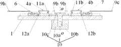
图1是本发明总体结构示意图。 Figure 1 is a schematic diagram of the overall structure of the present invention. the
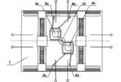
图2是本发明总体结构剖视图。 Fig. 2 is a sectional view of the overall structure of the present invention. the
图3是回转转接台与工件台、并联防转机构装配结构示意图。 Fig. 3 is a schematic diagram of the assembly structure of the rotary transfer table, the workpiece table, and the parallel anti-rotation mechanism. the
图4是第一工件台轴测图。 Fig. 4 is an isometric view of the first workpiece table. the
图5、6、7、8、9、10、11是双工件台换台流程示意图。 Figures 5, 6, 7, 8, 9, 10, and 11 are schematic diagrams of the process of changing two workpiece stages. the
图中件号:1-基台;2-曝光工位;3-预处理工位;4a-第一工件台;4b-第二工件台;5-Y向长行程直线运动单元;5a-Y向第一直线电机;5b-Y向第一静压气浮导轨;5c-Y向第二直线电机;5d-Y向第二静压气浮导轨;6-X向第一长行程直线运动单元;6a-X向第一直线电机动子;6b-X向第一直线电机定子;6c-X向第一静压气浮导轨;6d-第一承载梁;7-X向第二长行程直线运动单元;7a-X向第二直线电机动子;7b-X向第二直线电机定子;7c-X向第二静压气浮导轨;7d-第二承载梁;8a-第一并联杆;8b-第二并联杆;8c-第三并联杆;8d-第四并联杆;9a、9b、9c、9d、9e、9f、9g、9h-激光干涉仪;10-回转转接台;10a-回转电机定子;10b-回转电机动子;10c-回转换台抓卡装置;11a-第一工件台回转环套;11b-第二工件台回转环套;12a-第一工件台转接装置;12b-第二工件台转接装置。 Part number in the picture: 1-base platform; 2-exposure station; 3-pretreatment station; 4a-first workpiece table; 4b-second workpiece table; 5-Y long-stroke linear motion unit; 5a-Y To the first linear motor; 5b-Y to the first static pressure air bearing guide rail; 5c-Y to the second linear motor; 5d-Y to the second static pressure air bearing guide rail; 6-X to the first long stroke linear motion Unit; 6a-X to the first linear motor mover; 6b-X to the first linear motor stator; 6c-X to the first static pressure air bearing guide rail; 6d- the first load beam; 7-X to the second Long stroke linear motion unit; 7a-X to the second linear motor mover; 7b-X to the second linear motor stator; 7c-X to the second static pressure air bearing guide rail; 7d- the second load beam; 8a- the first 8b-second parallel rod; 8c-third parallel rod; 8d-fourth parallel rod; 9a, 9b, 9c, 9d, 9e, 9f, 9g, 9h-laser interferometer; 10-rotary adapter ; 10a-rotary motor stator; 10b-rotary motor mover; 10c-rotary conversion table grabbing device; connecting device; 12b-the second workpiece platform connecting device. the
具体实施方式Detailed ways
下面结合附图对本发明实施方案作进一步详细说明: Below in conjunction with accompanying drawing, embodiment of the present invention is described in further detail:
基于并联机构的双工件台同相位回转交换方法,该方法由三个节拍组成,第一个节拍是:第一工件台完成曝光工序、第二工件台完成预处理工序后,分别从曝光工位和预处理工位向基台中心运动,回转换台抓卡装置通过电磁吸附第一工件台的第一工件台回转环套和第二工件台的第二工件台回转环套,同时,X向第一直线电机动子和X向第二直线电机动子上的抓卡机构分别松开第一工件台的第一工件台转接装置和第二工件台的第二工件台转接装置,同时,第一并联杆和第二并联杆伸长,并抓卡住第一工件台,第三并联杆和第四并联杆伸长,并抓卡住第二工件台,实现两工件台与回转转接台相向对接;第二节拍是:回转转接台吸附住第一工件台和第二工件台绕基台中心轴线沿顺时针或逆时针回转180°(下一次回转交换沿逆时针或顺时针),同时第一并联杆和第二并联杆随第一工件台和Y向第一静压气浮导轨的距离远近而自动伸缩,防止第一工件台在换台过程中回转运动带来的相位变化;同时第三并联杆和第四并联杆随第二工件台和Y向第二静压气浮导轨的距离远近而自动伸缩,防止第二工件台在换台过程中回转运动带来的相位变化,实现第一工件台和第二工件台在整个回转换台传动过程中的同相位;第三个节拍是:回转转接台回转180°后,回转换台抓卡装置放开第一工件台的第一工件台回转环套和第二工件台的第二工件台回转环套;同时X向第一直线电机动子上的抓卡机构抓卡住第二工件台的第二工件台转接装置,并运动到曝光工位,X向第二直线电机动子上的抓卡机构抓卡住第一工件台的第一工件台转接装置,并运动到预处理工位,实现两工件台与回转转接台反向分离并到各自工位;通过上述三个节拍完成基于并联机构的双工件台同相位回转交换。 Based on the parallel mechanism, the double-workpiece stage rotation exchange method in the same phase is composed of three beats. The first beat is: after the first worktable completes the exposure process and the second workbench completes the pretreatment process, respectively from the exposure work The station and the pretreatment station move to the center of the abutment, and the clamping device of the rotary conversion table electromagnetically absorbs the first workpiece table rotary ring sleeve of the first workpiece table and the second workpiece table rotary ring sleeve of the second workpiece table. At the same time, X Loosen the first workpiece table adapter device of the first workpiece table and the second workpiece table adapter device of the second workpiece table respectively to the gripping mechanism on the first linear motor mover and the X-direction second linear motor mover , at the same time, the first parallel rod and the second parallel rod elongate and grab the first workpiece table, and the third parallel rod and the fourth parallel rod elongate and grab the second workpiece table to realize the two workpiece tables and The rotary transfer table is oppositely docked; the second beat is: the rotary transfer table absorbs the first workpiece table and the second workpiece table and rotates 180° clockwise or counterclockwise around the central axis of the abutment (the next rotary exchange is along the counterclockwise or counterclockwise direction). Clockwise), at the same time, the first parallel rod and the second parallel rod automatically expand and contract with the distance between the first workpiece table and the Y-direction first static pressure air bearing guide rail, so as to prevent the first workpiece table from being caused by the rotary motion during the table change process. At the same time, the third parallel rod and the fourth parallel rod automatically expand and contract with the distance between the second workpiece table and the second static pressure air bearing guide rail in the Y direction, so as to prevent the second workpiece table from being caused by the rotary motion during the table change process. The phase change of the first workpiece table and the second workpiece table are in the same phase during the entire transmission process of the rotary transfer table; the third beat is: after the rotary transfer table rotates 180°, the clamping device of the rotary transfer table releases the first The first workpiece table rotary ring sleeve of the first workpiece table and the second workpiece table rotary ring sleeve of the second workpiece table; at the same time, the clamping mechanism on the X-direction first linear motor mover grabs the second workpiece table. Workpiece table transfer device, and move to the exposure station, the clamp mechanism on the X-direction second linear motor mover grabs the first work table transfer device of the first work table, and moves to the pretreatment station, Realize the reverse separation of the two workpiece tables from the rotary transfer table and go to their respective stations; complete the same-phase rotary exchange of the double workpiece tables based on the parallel mechanism through the above three beats. the
基于并联机构的双工件台同相位回转交换装置,该装置包括基台1、第一工件台4a、第二工件台4b,基台1长边Y方向两端为曝光工位2和预处理工位3,第一工件台4a和第二工件台4b分别运行于曝光工位2和预处理工位3,沿基台1长边两侧对应分别设置由Y向第一直线电机5a、Y向第一静压气浮导轨5b和由Y向第二直线电机5c、Y向第二静压气浮导轨5d构成的两个Y向长行程直线运动单元5,曝光工位2上设置有由X向第一直线电机动子6a、X向第一直线电机定子6b、X向第一静压气浮导轨6c以及第一承载梁6d构成的X向第一长行程直线运动单元6,预处理工位3上设置有由X向第二直线电机动子7a、X向第二直线电机定子7b、X向第二静压气浮导轨7c以及第二承载梁7d构成的X向第二长行程直线运动单元7,在基台1四周装有激光干涉仪9a、9b、9c、9d、9e、9f、9g、9h;第一工件台4a和第二工件台4b分别配装在X向第一长行程 直线运动单元6和X向第二长行程直线运动单元7上,X向第一长行程直线运动单元6和X向第二长行程直线运动单元7分别与Y向长行程直线运动单元5成H型配置;在基台1上位于曝光工位2和预处理工位3之间部位处配装一个回转转接台10,回转转接台10包括回转电机定子10a、回转电机动子10b和回转换台抓卡装置10c,其中回转电机定子10a固装在基台1下侧部上,回转电机动子10b可转动地配装在回转电机定子10a上,在回转电机动子10b上端部上固装回转换台抓卡装置10c;在第一工件台4a中部设置第一工件台回转环套11a,在第一工件台4a底部X向侧面设置第一工件台转接装置12a;在第二工件台4b中部设置第二工件台回转环套11b,在第二工件台4b底部X向侧面设置第二工件台转接装置12b;在Y向第一静压气浮导轨5b和第一工件台4a之间连接设置由两个长度可伸缩的第一并联杆8a和第二并联杆8b组成的第一并联防转机构,在Y向第二静压气浮导轨5d和第二工件台4b之间连接设置由两个长度可伸缩的第三并联杆8c和第四并联杆8d组成的第二并联防转机构;第一工件台4a和第二工件台4b底面为气浮面,且第一工件台4a和第二工件台4b气浮在基台1之上;第一工件台回转环套11a与第一工件台4a的接触环面为静压气浮轴承,回转换台时套与台做相对回转运动;第二工件台回转环套11b与第二工件台4b的接触面为气浮环面,回转换台时套与台做相对回转运动;在运行过程中,激光干涉仪9a、9b、9c、9d、9e、9f、9g、9h发出的光束始终与第一工件台4a、第二工件台4b对应的侧面反射镜垂直;Y向第一直线电机5a、Y向第二直线电机5c、X向第一直线电机动子6a、X向第一直线电机定子6b、X向第二直线电机动子7a、X向第二直线电机定子7b采用平板电机,或采用U型槽式电机。 The same-phase rotary exchange device for double workpiece tables based on a parallel mechanism, the device includes a
本发明提出的基于并联机构的双工件台同相位回转交换装置工作流程如下: The working process of the parallel mechanism-based double-workpiece rotary exchange device in the same phase as proposed by the present invention is as follows:
如图5所示,初始工作状态,处于曝光工位2的第一工件台4a预对准完毕, 处于预处理工位3的第二工件台4b装载新硅片完毕;接下来,处于曝光工位2的第一工件台4a开始进行曝光处理,与此同时处于预处理工位3的第二工件台4b开始进行预对准处理。两工件台完成本工位所需时间不相同,一般曝光处理时间较长,位于预处理工位3的第二工件台4b完成对准工作后处于等待状态,当位于曝光工位2的第一工件台4a完成曝光工作后,准备进行工件台交换。 As shown in Figure 5, in the initial working state, the pre-alignment of the first workpiece table 4a in the
如图6所示,第一工件台4a完成曝光工序、第二工件台4b完成预处理工序后,分别从曝光工位2和预处理工位3向基台1中心运动,回转换台抓卡装置10c通过电磁吸附第一工件台4a的第一工件台回转环套11a和第二工件台4b的第二工件台回转环套11b,同时,X向第一直线电机动子6a和X向第二直线电机动子7a上的抓卡机构分别松开第一工件台4a的第一工件台转接装置12a和第二工件台4b的第二工件台转接装置12b。 As shown in Figure 6, after the first workpiece table 4a completes the exposure process and the second workpiece table 4b completes the pretreatment process, it moves from the
如图7、图8、图9、图10所示,回转转接台10吸附住第一工件台4a和第二工件台4b绕基台1中心回转180°;同时第一并联杆8a和第二并联杆8b随第一工件台4a的位置变化而自动伸缩,防止第一工件台4a在换台过程中回转运动带来的相位变化;同时第三并联杆8c和第四并联杆8d随第二工件台4b位置变化而自动伸缩,防止第二工件台4b在换台过程中回转运动带来的相位变化,实现第一工件台4a和第二工件台4b在整个回转换台传动过程中的同相位。 As shown in Figure 7, Figure 8, Figure 9, and Figure 10, the rotary transfer table 10 absorbs the first workpiece table 4a and the second workpiece table 4b and rotates 180° around the center of the
如图11所示,回转转接台10回转180°后,回转换台抓卡装置10c放开第一工件台4a的第一工件台回转环套11a和第二工件台4b的第二工件台回转环套11b,X向第一直线电机动子6a上的抓卡机构抓卡住第二工件台4b的第二工件台转接装置12b,并运动到曝光工位,X向第二直线电机动子7a上的抓卡机构抓卡住第一工件台4a的第一工件台转接装置12a,并运动到预处理工位;通过上述三个节拍完成了基于并联机构的双工件台同相位回转交换。 As shown in Figure 11, after the rotary transfer table 10 rotates 180°, the
Claims (2)
Translated fromChinesePriority Applications (1)
| Application Number | Priority Date | Filing Date | Title |
|---|---|---|---|
| CN 201110377373CN102402133B (en) | 2011-11-12 | 2011-11-12 | Double-workpiece-platform same-phase rotation exchange method based on parallel connection mechanisms, and device thereof |
Applications Claiming Priority (1)
| Application Number | Priority Date | Filing Date | Title |
|---|---|---|---|
| CN 201110377373CN102402133B (en) | 2011-11-12 | 2011-11-12 | Double-workpiece-platform same-phase rotation exchange method based on parallel connection mechanisms, and device thereof |
Publications (2)
| Publication Number | Publication Date |
|---|---|
| CN102402133A CN102402133A (en) | 2012-04-04 |
| CN102402133Btrue CN102402133B (en) | 2013-09-18 |
Family
ID=45884476
Family Applications (1)
| Application Number | Title | Priority Date | Filing Date |
|---|---|---|---|
| CN 201110377373Expired - Fee RelatedCN102402133B (en) | 2011-11-12 | 2011-11-12 | Double-workpiece-platform same-phase rotation exchange method based on parallel connection mechanisms, and device thereof |
Country Status (1)
| Country | Link |
|---|---|
| CN (1) | CN102402133B (en) |
Families Citing this family (6)
| Publication number | Priority date | Publication date | Assignee | Title |
|---|---|---|---|---|
| CN104375388B (en)* | 2014-10-13 | 2016-09-14 | 江苏影速光电技术有限公司 | A kind of multi-work piece platform direct-write photoetching system |
| CN105319868B (en)* | 2015-08-06 | 2018-05-08 | 南京全弗精密机械有限公司 | A kind of double-workpiece-table zapping rotating device and its application method |
| CN105005180A (en)* | 2015-08-06 | 2015-10-28 | 哈尔滨工业大学 | Automatic rotation device for dual-workpiece-stage changing based on lifting lever mechanism |
| CN105487348B (en)* | 2016-01-14 | 2017-09-22 | 哈尔滨工业大学 | Dynamic magnet steel magnetic based on active balancing quality floats double-workpiece-table vector circular arc channel switching method and device |
| CN106527056B (en)* | 2016-12-20 | 2019-03-12 | 湖北凯昌光电科技有限公司 | A kind of single table surface write-through exposure machine |
| CN108663907B (en)* | 2017-03-31 | 2019-12-24 | 上海微电子装备(集团)股份有限公司 | Substrate table system, lithographic apparatus and lithographic method |
Family Cites Families (4)
| Publication number | Priority date | Publication date | Assignee | Title |
|---|---|---|---|---|
| EP0634699A1 (en)* | 1993-07-16 | 1995-01-18 | Semiconductor Systems, Inc. | Clustered photolithography system |
| JP3919782B2 (en)* | 2004-10-08 | 2007-05-30 | キヤノン株式会社 | Exposure apparatus and device manufacturing method |
| CN101694560B (en)* | 2009-04-03 | 2011-08-17 | 清华大学 | Silicon wafer stage double-stage exchange system by adopting air-floatation planar motor |
| JP2011018861A (en)* | 2009-07-10 | 2011-01-27 | Canon Inc | Exposure apparatus and exposure method, as well as method of manufacturing device employing the same |
- 2011
- 2011-11-12CNCN 201110377373patent/CN102402133B/ennot_activeExpired - Fee Related
Also Published As
| Publication number | Publication date |
|---|---|
| CN102402133A (en) | 2012-04-04 |
Similar Documents
| Publication | Publication Date | Title |
|---|---|---|
| CN102495528B (en) | Double-workpiece-table same-phase rotation exchange method and device based on follow-up rotation-resisting mechanisms | |
| CN102402133B (en) | Double-workpiece-platform same-phase rotation exchange method based on parallel connection mechanisms, and device thereof | |
| CN100470379C (en) | A dual-stage exchange system for silicon wafer stages of a lithography machine | |
| CN201364459Y (en) | Double wafer stage exchanging device of photo-etching machine | |
| CN102393613A (en) | Double workpiece stage rotary exchange device based on synchronous gear direction adjustment | |
| CN1200321C (en) | Step-by-step projection photo-etching machine double set shifting exposure ultra-sophisticated positioning silicon chip bench system | |
| WO2017121127A1 (en) | Dynamic-magnetic steel magnetic levitation double-workpiece-stage vector arc switching method and apparatus based on planar grating measurement | |
| CN101963763B (en) | Double-driving double-bridge table changing station-based double-workpiece table high-accuracy exchange device | |
| WO2017121128A1 (en) | Dynamic magnetic steel magnetic levitation dual workpiece stage vector arc stage switching method and device based on rotary balance mass | |
| CN101727019A (en) | Double-platform exchange system for silicon chip platform of lithography machine and exchange method thereof | |
| CN105629673A (en) | Vector arc rotary stage switching method and device for double interferometer measurement-based gas-magnetic-combined air floatation workpiece stage | |
| WO2017121126A1 (en) | Dynamic-magnetic steel magnetic levitation double-workpiece-stage vector arc switching method and apparatus based on wireless energy transmission | |
| CN102393609B (en) | Girder-type single/double guide rail double-drive step-scanning double-workpiece exchange device and method | |
| CN102508414B (en) | Rotary exchanging method and rotary exchanging device for double workpiece platforms based on synchronous steering of turntable gear | |
| CN102520587B (en) | Two-workpiece-platform rotary exchange method and device based on cable-box anti-rotation mechanisms | |
| CN105629674A (en) | Vector arc stage switching method and device for double dual-layer water cooling-based dynamic magnetic steel type magnetic levitation workpiece stages | |
| CN102419517A (en) | Exchange apparatus and method for double-workpiece stage based on double-guide rail double-drive step scanning | |
| CN102495531B (en) | Double-stage revolving and switching method and apparatus based on independent synchronic direction-regulation | |
| CN102495529B (en) | Lintel type dual-guide rail dual-drive stepping scanning double silicon wafer stage exchanging device and method thereof | |
| CN102723303B (en) | XY two-coordinate air-floatation positioning platform | |
| CN102393608B (en) | Double workpiece table revolution exchanging method and device based on self rotating direction adjustment of measurement positions | |
| CN105629675A (en) | Vector arc stage switching method and device for double hexagon magnetic steel layout-based dynamic magnetic steel type magnetic levitation workpiece stages | |
| CN105425548A (en) | Moving coil magnetic-levitation wireless micro-motion-stage vector circular-arc exchange method and device based on herringbone coil arrangement | |
| CN202712146U (en) | XY two-coordinate air-floatation positioning platform | |
| CN105549330A (en) | Active balanced mass moving coil magnetic-suspension dual workpiece stage vector arc based stage exchanging method and device |
Legal Events
| Date | Code | Title | Description |
|---|---|---|---|
| C06 | Publication | ||
| PB01 | Publication | ||
| C10 | Entry into substantive examination | ||
| SE01 | Entry into force of request for substantive examination | ||
| C14 | Grant of patent or utility model | ||
| GR01 | Patent grant | ||
| CF01 | Termination of patent right due to non-payment of annual fee | Granted publication date:20130918 Termination date:20211112 | |
| CF01 | Termination of patent right due to non-payment of annual fee |