CN102401250B - lamps - Google Patents
lampsDownload PDFInfo
- Publication number
- CN102401250B CN102401250BCN2010102861153ACN201010286115ACN102401250BCN 102401250 BCN102401250 BCN 102401250BCN 2010102861153 ACN2010102861153 ACN 2010102861153ACN 201010286115 ACN201010286115 ACN 201010286115ACN 102401250 BCN102401250 BCN 102401250B
- Authority
- CN
- China
- Prior art keywords
- base
- combined
- circuit board
- emitting element
- shell
- Prior art date
- Legal status (The legal status is an assumption and is not a legal conclusion. Google has not performed a legal analysis and makes no representation as to the accuracy of the status listed.)
- Expired - Fee Related
Links
- 230000017525heat dissipationEffects0.000claimsabstractdescription47
- 238000001816coolingMethods0.000claimsdescription30
- 230000008878couplingEffects0.000claimsdescription9
- 238000010168coupling processMethods0.000claimsdescription9
- 238000005859coupling reactionMethods0.000claimsdescription9
- 230000002093peripheral effectEffects0.000claimsdescription7
- 238000004891communicationMethods0.000claimsdescription2
- 230000000149penetrating effectEffects0.000claims1
- 230000000694effectsEffects0.000abstractdescription22
- 230000005855radiationEffects0.000abstract2
- 238000004519manufacturing processMethods0.000description3
- 238000009423ventilationMethods0.000description3
- 238000000034methodMethods0.000description2
- 230000000903blocking effectEffects0.000description1
- 238000010586diagramMethods0.000description1
- 230000005611electricityEffects0.000description1
- 238000003466weldingMethods0.000description1
Images


Landscapes
- Cooling Or The Like Of Electrical Apparatus (AREA)
Abstract
Description
Translated fromChinese技术领域technical field
本发明是关于一种灯具,尤其是一种可借助散热器构成一中空壳体的灯具。The invention relates to a lamp, especially a lamp which can form a hollow shell by means of a radiator.
背景技术Background technique
请参照图1所示,现有灯具8具有一散热本体81,该散热本体81的外周面设有数个鳍片811;又,散热本体81的一端结合一发光元件82,另一端设置一电连接件83,该电连接件83电性连接该发光元件82;借此,该电连接件83通电后可通过如电路板等控制组件控制该发光元件82投射灯光;借此,当该发光元件82及该电连接件83于运作过程中产生热量时,即可利用该散热本体81的热传导作用辅助进行散热。Please refer to Fig. 1, the existing lamp 8 has a
然而,现有灯具8的散热本体81虽然可吸收该发光元件82及该电连接件83运作时所产生的热量。只是该散热本体81的体积必须足够提供该发光元件82及该电连接件83预定的散热作用,因此,该散热本体81的整体体积略为笨重,造成使用上的诸多不便;再者,由于该灯具8并无类似“通风孔”及“散热风扇”的设计;因此,导致该发光元件82及该电连接件83无法达到良好的通风散热效果,容易影响该灯具8的整体散热效果,令该发光元件82的使用寿命降低。However, although the
为解决前述现有灯具8的缺点,如图2所示,揭示另一种现有灯具9,该灯具9包含一第一外壳91、一第二外壳92、一电路板93、一散热模组94及一发光元件95。该第一外壳91设有数个入风孔911,该第二外壳92设有数个出风孔921,该电路板93、散热模组94及发光元件95则设置于该第一外壳91及第二外壳92相互对组后所构成的中空壳体内;其中该散热模组94由一散热风扇941及一散热器942所构成,该电路板93电性连接该散热风扇941及发光元件95,该发光元件95结合该散热器942。In order to solve the shortcomings of the aforementioned existing lamp 8, as shown in Figure 2, another existing
当该发光元件95因通电产生热源时,则可利用该电路板93驱动该散热风扇941工作,以便经由各该入风孔911引入外界气流,并配合该散热器942传导该发光元件95热源所产生的热量,再进一步利用该散热风扇941使该外界气流经由各该出风孔921将热量传递至外界空间,以达到预定的散热效果,进而可延长该发光元件95的使用寿命。When the light-
上述现有灯具9于实际使用时,仍有如下所述的诸多缺点:When the above-mentioned existing
1、结构复杂及组装不便:该灯具9必须利用该第一外壳91及该第二外壳92所对组而成的中空壳体,方可容置该电路板93、散热模组94及发光元件95等构件;因此,整体结构相对较为复杂,并导致组装上较为不便;再者,该第一外壳91及该第二外壳92必须另行加工形成该入风孔911及该出风孔921,不仅制作便利性不佳,也造成制造成本的提高。1. Complex structure and inconvenient assembly: the
2、散热效果不佳:该散热风扇941自该入风孔911所引入的外界气流,主要用以针对该发光元件95进行散热,以该入风孔911及该出风孔921的设计而言,对该电路板93所能提供的散热效果仍相当有限,因此,现有灯具9的散热功能仍有改善的空间。2. The heat dissipation effect is not good: the external airflow introduced by the
发明内容Contents of the invention
本发明提供一种灯具,以有效降低整体结构复度,为其主要的发明目的。The invention provides a lamp to effectively reduce the complexity of the overall structure, which is the main purpose of the invention.
本发明的次一目的,是提供一种组装上更为方便的灯具。Another object of the present invention is to provide a lamp that is more convenient to assemble.
本发明的另一目的,是提供一种散热效果佳的灯具。Another object of the present invention is to provide a lamp with good heat dissipation effect.
根据本发明灯具,包含:一散热器,包含一基座及一结合件,该基座设有一第一导风部及一固定部,该结合件设置于该基座的外周边,且该结合件与该基座之间形成一第二导风部;一发光元件,结合于该散热器的基座;一外壳,结合于该散热器的结合件,该外壳与该散热器的间形成一容置空间,该容置空间与该第一导风部及该第二导风部为相互连通设置;一散热风扇,结合于该基座的固定部,该散热风扇对位该第一导风部;及一电路板,结合于该容置空间,该电路板电性连结该发光元件及该散热风扇,且该电路板也电性连接有一电连接件,该电连接件的一端穿伸至该外壳的外部。According to the lamp of the present invention, it includes: a heat sink, including a base and a joint, the base is provided with a first air guiding part and a fixing part, the joint is arranged on the outer periphery of the base, and the joint A second air guide part is formed between the part and the base; a light-emitting element is combined with the base of the radiator; a shell is combined with the joint part of the radiator, and a gap is formed between the shell and the radiator. an accommodating space, the accommodating space communicates with the first air guide part and the second air guide part; a heat dissipation fan is combined with the fixed part of the base, and the heat dissipation fan is aligned with the first air guide part; and a circuit board, combined in the accommodating space, the circuit board is electrically connected to the light-emitting element and the cooling fan, and the circuit board is also electrically connected to an electrical connector, and one end of the electrical connector extends to the exterior of the enclosure.
基于相同技术概念下,本发明灯具也可包含:一散热器,包含一基座及一结合件,该基座设有一第一导风部及一固定部,该结合件设置于该基座的外周边;一发光元件,结合于该散热器的基座;一外壳,结合于该散热器的结合件,该外壳设有一第二导风部,且该外壳与该散热器之间形成一容置空间,该容置空间与该第一导风部及该第二导风部为相互连通设置;一散热风扇,结合于该基座的固定部,该散热风扇对位该第一导风部;及一电路板,结合于该容置空间,该电路板电性连结该发光元件及该散热风扇,且该电路板也电性连接有一电连接件,该电连接件的一端穿伸至该外壳的外部。Based on the same technical concept, the lamp of the present invention may also include: a radiator, including a base and a joint, the base is provided with a first air guiding part and a fixing part, the joint is arranged on the base Outer periphery; a light-emitting element, combined with the base of the radiator; a casing, combined with the joint of the radiator, the casing is provided with a second air guide part, and a container is formed between the casing and the radiator An accommodating space, the accommodating space communicates with the first air guide part and the second air guide part; a heat dissipation fan, combined with the fixed part of the base, the heat dissipation fan and a circuit board, combined in the accommodating space, the circuit board is electrically connected to the light-emitting element and the cooling fan, and the circuit board is also electrically connected to an electrical connector, and one end of the electrical connector extends to the exterior of the enclosure.
附图说明Description of drawings
图1:现有第一种灯具的立体外观图。Figure 1: The three-dimensional appearance diagram of the first type of lamp.
图2:现有第二种灯具的组合剖视图。Figure 2: A combined sectional view of the second existing lamp.
图3:本发明第一实施例的灯具的立体分解图。Fig. 3: An exploded perspective view of the lamp of the first embodiment of the present invention.
图4:本发明第一实施例的灯具的组合剖视图。Fig. 4: An assembled sectional view of the lamp of the first embodiment of the present invention.
图5:本发明灯具的散热器另一实施方式的俯视图。Fig. 5: A top view of another embodiment of the radiator of the lamp of the present invention.
图6:本发明第二实施例的灯具的立体分解图。Fig. 6: An exploded perspective view of the lamp of the second embodiment of the present invention.
图7:本发明第二实施例的灯具的组合剖视图。Fig. 7: An assembled sectional view of the lamp of the second embodiment of the present invention.
图8:本发明第三实施例的灯具的立体分解图。Fig. 8: An exploded perspective view of the lamp of the third embodiment of the present invention.
图9:本发明第三实施例的灯具的组合剖视图。Fig. 9: An assembled sectional view of the lamp of the third embodiment of the present invention.
主要元件符号说明:Description of main component symbols:
1、1’、1”散热器 11基座 11a座板1. 1’, 1”
11b环墙 111第一导风部 112固定部 12结合件
12a结合环圈 12b连接肋 12c凸块 12d环凸缘12a combined
12e支撑块 121第二导风部 2发光元件 3、3’外壳
31容置空间 32开口 33穿孔 34第二导风部31 Accommodating
4散热风扇 41扇框 411挡止部 42扇轮4
43固定元件 5电路板 51电连接件 8灯具43 Fixed
81散热本体 811鳍片 82发光元件 83电连接件81
9灯具 91第一外壳 911入风孔 92第二外壳9
921出风孔 93电路板 94散热模组 941散热风扇921
942散热器 95发光元件942 Radiator 95 Light-emitting Elements
具体实施方式Detailed ways
为让本发明的上述及其他目的、特征及优点能更明显易懂,下文特举本发明的较佳实施例,并配合附图,作详细说明如下:In order to make the above-mentioned and other objects, features and advantages of the present invention more comprehensible, the preferred embodiments of the present invention are specifically cited below, together with the accompanying drawings, as follows:
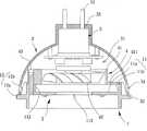
请参照图3及4所示,本发明第一实施例的灯具包含一散热器1、一发光元件2、一外壳3、一散热风扇4及一电路板5。其中该散热器1可供该发光元件2结合;该外壳3结合该散热器1以构成一中空壳体,该中空壳体用以容置该散热风扇4及该电路板5;该散热风扇4另结合该散热器1,用以搭配该散热器1提供该发光元件2预定的散热效果;该电路板5电性连结该散热风扇4,用以驱动该散热风扇4旋转工作。Referring to FIGS. 3 and 4 , the lamp according to the first embodiment of the present invention includes a
该散热器1包含一基座11及一结合件12。该基座11设有一第一导风部111及一固定部112,其中该第一导风部111为各种能够供气流通过的结构设计,并可提供入风或出风功能(第一导风部111为出风或入风功能依散热风扇4的旋转方向而定),该固定部112则为各种能够供该散热风扇4结合固定的结构设计;又,该结合件12设置于该基座11的外周边,且该结合件12与该基座11之间形成一第二导风部121,该第二导风部121同样为各种能够供气流通过的结构设计,亦可提供出风或入风功能(第二导风部121为出风或入风功能同样依散热风扇4的旋转方向而定)。The
本实施例中,上述该基座11具有一座板11a,该座板11a的外周缘形成一环墙11b;借此,该第一导风部111为形成于该座板11a及环墙11b的接邻部位的至少一个通道,该通道可作为出风孔的用途,而该固定部112为形成于该环墙11b的内侧的数个固定柱。又,该结合件12具有一结合环圈12a,该结合环圈12a以数个连接肋12b连接该环墙11b;借此,该第二导风部121为形成于各该连接肋12b之间的数个通道,该通道可作为入风孔的用途;或者,如图5所示,该结合件12亦可为形成于该环墙11b的外周面的数个凸块12c,该第二导风部121为形成于各该凸块12c之间的数个通道,该通道可作为入风孔的用途。In this embodiment, the above-mentioned
该发光元件2结合于该散热器1的基座11,该发光元件2可选自发光二极体(LED)、灯泡或其他可通电后产生灯光的构件。本实施例中,该发光元件2结合于该散热器1的座板11a的一侧表面。The light-emitting
该外壳3结合于该散热器1的结合件12,使该外壳3与该散热器1之间形成一容置空间31(如图4所示),该容置空间31与该第一导风部111及该第二导风部121为相互连通设置。本实施例中,该外壳3为半球形的中空壳体,该中空壳体的一端设有一开口32,另一端设有一穿孔33,又,该外壳3以该开口32的端缘固定于该结合件12的结合环圈12a,该固定方式可采用如焊接、粘着、锁固、卡扣、......等。The
该散热风扇4结合于该基座11的固定部112,且该散热风扇4对位该第一导风部111。本实施例中,该散热风扇4具有一扇框41,该扇框41内侧设置可旋转的一扇轮42,该扇框41可借助数个固定元件43(如螺丝或具有相同固定功能的构件)与该固定部112(即数个固定柱)相互固定,令该扇框41稳固结合于该基座11上;另外,该扇框41的外侧周缘可形成一挡止部411,该挡止部411结合该基座11,且该挡止部411可用以防止流通于该第一导风部111的气流产生逆流现象。The
该电路板5结合于该容置空间31,该电路板5电性连结该发光元件2及该散热风扇4,用以控制该发光元件2投射灯光,以及驱动该散热风扇4的扇轮42旋转工作;该电路板5另电性连接有一电连接件51,该电连接件51的一端裸露于该外壳3的外部。本实施例中,该电路板5的电连接件51的一端穿伸于该外壳3的穿孔33的外部。The
本发明灯具于实际使用时,该灯具可装设于如墙壁、天花板或桌上等地点的灯座(未绘示),并利用该电连接件51外接一般供电系统,使该发光元件2可通电产生灯光,并提供该散热风扇4运作的主要电力来源。再者,当该发光元件2及该电路板5因通电产生热源时,借助该第一导风部111及第二导风部121连通该容置空间31、该电路板5位于该容置空间31、以及发光元件2结合该散热器1等结构设计,该第一导风部111及第二导风部121即可搭配该散热风扇4提供该发光元件2及该电路板5良好的通风散热效果。When the lamp of the present invention is actually used, the lamp can be installed on a lamp holder (not shown) such as a wall, a ceiling, or a table, and the
更详言之,如图4所示的实施例中,当该电路板5驱动该散热风扇4的扇轮42旋转工作时,该扇轮42可经由该第二导风部121引入气流,该气流可进入该容置空间31,对该电路板5预定的散热作用;再者,该散热器1可用以传导该发光元件2因通电所产生的热源,以便该扇轮42进一步导引气流经由该第一导风部111将该热源的热量传递至外界空间,以达到更佳的散热效果,进而可延长该发光元件2的使用寿命。More specifically, in the embodiment shown in FIG. 4 , when the
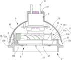
请参照图6及7所示,揭示本发明第二实施例的灯具,该灯具同样包含一散热器1’、一发光元件2、一外壳3’、一散热风扇4及一电路板5。其中本实施例的发光元件2、散热风扇4及电路板5与第一实施例所揭示的发光元件2、散热风扇4及电路板5仅外观形状略有不同,其主要结构特征仍大致相同,容不赘述。Please refer to Figures 6 and 7, which disclose a lamp according to a second embodiment of the present invention, which also includes a radiator 1 ', a
本发明第二实施例的散热器1’及外壳3’与第一实施例的散热器1及外壳3的主要的差异仅在于:该散热器1’的第一导风部111为形成于该座板11a的中央部位的至少一个通道,且该散热器1’未设有如第一实施例所述的该第二导风部121;又,该外壳3’则另设有可连通该容置空间31的一第二导风部34,本实施例中,该第二导风部34为贯穿该外壳3’的数个通道,该通道可作为入风孔的用途;借此,如图7所示的实施例中,当该散热风扇4的扇轮42旋转工作时,该扇轮42同样可经由该第二导风部34引入气流,以便该气流可经由该第一导风部111将该电路板5及该发光元件2运作时所产生的热量传递至外界空间,进而达到更佳的散热效果,也可延长该发光元件2的使用寿命。The main difference between the radiator 1' and the casing 3' of the second embodiment of the present invention and the
请参照图8及9所示,揭示本发明第三实施例的灯具,该灯具同样包含一散热器1”、一发光元件2、一外壳3、一散热风扇4及一电路板5。其中本实施例的发光元件2、外壳3、散热风扇4及电路板5与第一实施例所揭示的发光元件2、外壳3、散热风扇4及电路板5的主要结构特征仍大致相同,容不赘述。Please refer to Figures 8 and 9, which disclose a lamp according to a third embodiment of the present invention, which also includes a
本发明第三实施例的散热器1”与第一实施例的散热器1的主要的差异仅在于:该散热器1”的第一导风部111为形成于该座板11a的中央部位的至少一个通道;又,该结合件12具有环凸缘12d,该环凸缘12d表面凸出数个支撑块12e,该外壳3则以该开口32的端缘固定于该结合件12的支撑块12e;借此,该第二导风部121为径向形成于各该支撑块12e之间的数个通道,该通道可作为入风孔的用途;如图9所示的实施例中,当该散热风扇4的扇轮42旋转工作时,该扇轮42同样可经由该第二导风部121引入气流,以便该气流可经由该第一导风部111将该电路板5及该发光元件2运作时所产生的热量传递至外界空间,进而达到更佳的散热效果,也可延长该发光元件2的使用寿命。The main difference between the
又,该结合件12的环凸缘12d与该基座11的环墙11b的接邻部位可进一步形成一导弧面F,以便利用该导弧面提供一导流效果。Moreover, an arc-guiding surface F can be further formed at the adjacent portion of the
借助前揭的结构特征,本发明灯具的主要特点至少包含有:With the help of the structural features disclosed above, the main features of the lamp of the present invention at least include:
1、结构精简:借助该散热器1、1’、1”的结合件12设计,该外壳3、3’可与该散热器1、1’、1”相互对组以形成该容置空间31,该容置空间31则用以容置该发光元件2、散热风扇4及电路板5;因此,相较于如图2所示的现有灯具9必须利用该第一外壳91及该第二外壳92方可构成中空壳体的设计,本发明灯具则可直接利用该散热器1、1’、1”取代其中一外壳结构,故整体结构相对较为精简,且制作便利性亦佳,可达到有效降低整体结构复度的功效。1. Simplified structure: With the help of the design of the joint 12 of the
2、组装便利性佳:本发明灯具于实际组装时,仅须将该发光元件2及该散热风扇4结合于该散热器1、1’、1”,以及将该电路板5结合于该外壳3、3’后,再将该外壳3、3’与该散热器1、1’、1”相互对组即可完成组装作业;因此,整体组装步骤相当简易,可达到提升组装便利性的功效。2. Good assembly convenience: when the lamp of the present invention is actually assembled, it is only necessary to combine the light-emitting
3、散热效果佳:借助该第一导风部111及第二导风部121、34连通该容置空间31、该电路板5位于该容置空间31、以及发光元件2结合该散热器1、1’、1”等结构设计,该散热风扇4可引入外界气流流通于第一导风部111及第二导风部121、34,用以分别针对该发光元件2及该电路板5进行散热,故可达到提升散热效果的功效。3. Good heat dissipation effect: the
如上所述,本发明灯具确具结构精简、组装便利性佳及散热效果佳等诸多功效。As mentioned above, the lamp of the present invention has many functions such as simplified structure, good assembly convenience and good heat dissipation effect.
Claims (11)
Translated fromChinesePriority Applications (1)
| Application Number | Priority Date | Filing Date | Title |
|---|---|---|---|
| CN2010102861153ACN102401250B (en) | 2010-09-19 | 2010-09-19 | lamps |
Applications Claiming Priority (1)
| Application Number | Priority Date | Filing Date | Title |
|---|---|---|---|
| CN2010102861153ACN102401250B (en) | 2010-09-19 | 2010-09-19 | lamps |
Publications (2)
| Publication Number | Publication Date |
|---|---|
| CN102401250A CN102401250A (en) | 2012-04-04 |
| CN102401250Btrue CN102401250B (en) | 2013-09-04 |
Family
ID=45883735
Family Applications (1)
| Application Number | Title | Priority Date | Filing Date |
|---|---|---|---|
| CN2010102861153AExpired - Fee RelatedCN102401250B (en) | 2010-09-19 | 2010-09-19 | lamps |
Country Status (1)
| Country | Link |
|---|---|
| CN (1) | CN102401250B (en) |
Families Citing this family (5)
| Publication number | Priority date | Publication date | Assignee | Title |
|---|---|---|---|---|
| TWI481798B (en)* | 2012-04-11 | 2015-04-21 | Sunonwealth Electr Mach Ind Co | Lamp |
| TWI509192B (en)* | 2013-12-19 | 2015-11-21 | Sunonwealth Electr Mach Ind Co | Lamp and airing cover thereof |
| TWI529337B (en)* | 2014-03-04 | 2016-04-11 | 建準電機工業股份有限公司 | A lamp with airing functions |
| CN107631192A (en)* | 2017-11-01 | 2018-01-26 | 佛山市高明区云大机械科技有限公司 | A kind of heat-dissipation lamp bulb |
| CN107906387A (en)* | 2017-11-20 | 2018-04-13 | 佛山市德平灯饰有限公司 | A kind of light bulb with radiator structure |
Citations (4)
| Publication number | Priority date | Publication date | Assignee | Title |
|---|---|---|---|---|
| US6068385A (en)* | 1998-03-18 | 2000-05-30 | Hsieh; Jordan | Durable lamp having air cooled moveable bulb |
| CN201047575Y (en)* | 2007-02-12 | 2008-04-16 | 陈柏璋 | Improved lamp heat radiator |
| CN101672432A (en)* | 2008-09-11 | 2010-03-17 | 富准精密工业(深圳)有限公司 | Light-emitting diode (LED) lamp |
| CN101769521A (en)* | 2009-01-04 | 2010-07-07 | 亿光电子工业股份有限公司 | Heat dissipation device for light-emitting device and light-emitting device thereof |
Family Cites Families (1)
| Publication number | Priority date | Publication date | Assignee | Title |
|---|---|---|---|---|
| US7677770B2 (en)* | 2007-01-09 | 2010-03-16 | Lighting Science Group Corporation | Thermally-managed LED-based recessed down lights |
- 2010
- 2010-09-19CNCN2010102861153Apatent/CN102401250B/ennot_activeExpired - Fee Related
Patent Citations (4)
| Publication number | Priority date | Publication date | Assignee | Title |
|---|---|---|---|---|
| US6068385A (en)* | 1998-03-18 | 2000-05-30 | Hsieh; Jordan | Durable lamp having air cooled moveable bulb |
| CN201047575Y (en)* | 2007-02-12 | 2008-04-16 | 陈柏璋 | Improved lamp heat radiator |
| CN101672432A (en)* | 2008-09-11 | 2010-03-17 | 富准精密工业(深圳)有限公司 | Light-emitting diode (LED) lamp |
| CN101769521A (en)* | 2009-01-04 | 2010-07-07 | 亿光电子工业股份有限公司 | Heat dissipation device for light-emitting device and light-emitting device thereof |
Also Published As
| Publication number | Publication date |
|---|---|
| CN102401250A (en) | 2012-04-04 |
Similar Documents
| Publication | Publication Date | Title |
|---|---|---|
| TWI397650B (en) | Lamp | |
| US8319408B1 (en) | LED lamp with simplified structure | |
| CN103499033B (en) | Lamp fitting | |
| TWI583894B (en) | Ventilator with illumination function | |
| US9243792B2 (en) | Lamp | |
| US8292465B2 (en) | Lamp | |
| CN102679193B (en) | Lamp fitting | |
| TWI408312B (en) | Lamp | |
| CN103062646B (en) | Lamp fitting | |
| CN103185234B (en) | Lamp and heat dissipation unit thereof | |
| CN202629847U (en) | Lamp fitting | |
| CN102840468B (en) | Lamp fitting | |
| CN102401250B (en) | lamps | |
| EP3208522B1 (en) | Omnidirectional light emission led lamp | |
| TW201239258A (en) | Lamp | |
| US10571109B2 (en) | Illuminating device | |
| CN103423676B (en) | lamps | |
| CN101639163B (en) | lamps | |
| CN101813244A (en) | Lamp fitting | |
| CN103697344B (en) | Lamp fitting | |
| CN102853280B (en) | Lamp and lamp body thereof | |
| TW201537100A (en) | Lamp with ventilation function | |
| CN201382285Y (en) | Lamp fitting | |
| CN102444805A (en) | lamps | |
| TWM272039U (en) | Heat dissipation structure of lighting appliances |
Legal Events
| Date | Code | Title | Description |
|---|---|---|---|
| C06 | Publication | ||
| PB01 | Publication | ||
| C10 | Entry into substantive examination | ||
| SE01 | Entry into force of request for substantive examination | ||
| C14 | Grant of patent or utility model | ||
| GR01 | Patent grant | ||
| CF01 | Termination of patent right due to non-payment of annual fee | Granted publication date:20130904 Termination date:20170919 | |
| CF01 | Termination of patent right due to non-payment of annual fee |