CN102394396A - Contact for coaxial cable and end processing method for coaxial cable - Google Patents
Contact for coaxial cable and end processing method for coaxial cableDownload PDFInfo
- Publication number
- CN102394396A CN102394396ACN2011101684866ACN201110168486ACN102394396ACN 102394396 ACN102394396 ACN 102394396ACN 2011101684866 ACN2011101684866 ACN 2011101684866ACN 201110168486 ACN201110168486 ACN 201110168486ACN 102394396 ACN102394396 ACN 102394396A
- Authority
- CN
- China
- Prior art keywords
- coaxial cable
- crimping
- conductor
- barrel
- joint
- Prior art date
- Legal status (The legal status is an assumption and is not a legal conclusion. Google has not performed a legal analysis and makes no representation as to the accuracy of the status listed.)
- Granted
Links
Images


Classifications
- H—ELECTRICITY
- H01—ELECTRIC ELEMENTS
- H01R—ELECTRICALLY-CONDUCTIVE CONNECTIONS; STRUCTURAL ASSOCIATIONS OF A PLURALITY OF MUTUALLY-INSULATED ELECTRICAL CONNECTING ELEMENTS; COUPLING DEVICES; CURRENT COLLECTORS
- H01R43/00—Apparatus or processes specially adapted for manufacturing, assembling, maintaining, or repairing of line connectors or current collectors or for joining electric conductors
- H01R43/04—Apparatus or processes specially adapted for manufacturing, assembling, maintaining, or repairing of line connectors or current collectors or for joining electric conductors for forming connections by deformation, e.g. crimping tool
- H01R43/048—Crimping apparatus or processes
- H01R43/05—Crimping apparatus or processes with wire-insulation stripping
- H—ELECTRICITY
- H01—ELECTRIC ELEMENTS
- H01R—ELECTRICALLY-CONDUCTIVE CONNECTIONS; STRUCTURAL ASSOCIATIONS OF A PLURALITY OF MUTUALLY-INSULATED ELECTRICAL CONNECTING ELEMENTS; COUPLING DEVICES; CURRENT COLLECTORS
- H01R4/00—Electrically-conductive connections between two or more conductive members in direct contact, i.e. touching one another; Means for effecting or maintaining such contact; Electrically-conductive connections having two or more spaced connecting locations for conductors and using contact members penetrating insulation
- H01R4/10—Electrically-conductive connections between two or more conductive members in direct contact, i.e. touching one another; Means for effecting or maintaining such contact; Electrically-conductive connections having two or more spaced connecting locations for conductors and using contact members penetrating insulation effected solely by twisting, wrapping, bending, crimping, or other permanent deformation
- H01R4/18—Electrically-conductive connections between two or more conductive members in direct contact, i.e. touching one another; Means for effecting or maintaining such contact; Electrically-conductive connections having two or more spaced connecting locations for conductors and using contact members penetrating insulation effected solely by twisting, wrapping, bending, crimping, or other permanent deformation by crimping
- H01R4/183—Electrically-conductive connections between two or more conductive members in direct contact, i.e. touching one another; Means for effecting or maintaining such contact; Electrically-conductive connections having two or more spaced connecting locations for conductors and using contact members penetrating insulation effected solely by twisting, wrapping, bending, crimping, or other permanent deformation by crimping for cylindrical elongated bodies, e.g. cables having circular cross-section
- H01R4/184—Electrically-conductive connections between two or more conductive members in direct contact, i.e. touching one another; Means for effecting or maintaining such contact; Electrically-conductive connections having two or more spaced connecting locations for conductors and using contact members penetrating insulation effected solely by twisting, wrapping, bending, crimping, or other permanent deformation by crimping for cylindrical elongated bodies, e.g. cables having circular cross-section comprising a U-shaped wire-receiving portion
- H01R4/185—Electrically-conductive connections between two or more conductive members in direct contact, i.e. touching one another; Means for effecting or maintaining such contact; Electrically-conductive connections having two or more spaced connecting locations for conductors and using contact members penetrating insulation effected solely by twisting, wrapping, bending, crimping, or other permanent deformation by crimping for cylindrical elongated bodies, e.g. cables having circular cross-section comprising a U-shaped wire-receiving portion combined with a U-shaped insulation-receiving portion
- H—ELECTRICITY
- H01—ELECTRIC ELEMENTS
- H01R—ELECTRICALLY-CONDUCTIVE CONNECTIONS; STRUCTURAL ASSOCIATIONS OF A PLURALITY OF MUTUALLY-INSULATED ELECTRICAL CONNECTING ELEMENTS; COUPLING DEVICES; CURRENT COLLECTORS
- H01R9/00—Structural associations of a plurality of mutually-insulated electrical connecting elements, e.g. terminal strips or terminal blocks; Terminals or binding posts mounted upon a base or in a case; Bases therefor
- H01R9/03—Connectors arranged to contact a plurality of the conductors of a multiconductor cable, e.g. tapping connections
- H01R9/05—Connectors arranged to contact a plurality of the conductors of a multiconductor cable, e.g. tapping connections for coaxial cables
- Y—GENERAL TAGGING OF NEW TECHNOLOGICAL DEVELOPMENTS; GENERAL TAGGING OF CROSS-SECTIONAL TECHNOLOGIES SPANNING OVER SEVERAL SECTIONS OF THE IPC; TECHNICAL SUBJECTS COVERED BY FORMER USPC CROSS-REFERENCE ART COLLECTIONS [XRACs] AND DIGESTS
- Y10—TECHNICAL SUBJECTS COVERED BY FORMER USPC
- Y10T—TECHNICAL SUBJECTS COVERED BY FORMER US CLASSIFICATION
- Y10T29/00—Metal working
- Y10T29/49—Method of mechanical manufacture
- Y10T29/49002—Electrical device making
- Y10T29/49117—Conductor or circuit manufacturing
- Y10T29/49174—Assembling terminal to elongated conductor
- Y10T29/49181—Assembling terminal to elongated conductor by deforming
- Y10T29/49185—Assembling terminal to elongated conductor by deforming of terminal
- Y10T29/49192—Assembling terminal to elongated conductor by deforming of terminal with insulation removal
Landscapes
- Engineering & Computer Science (AREA)
- Manufacturing & Machinery (AREA)
- Coupling Device And Connection With Printed Circuit (AREA)
- Connections Effected By Soldering, Adhesion, Or Permanent Deformation (AREA)
Abstract
Translated fromChinese
Description
Translated fromChinese技术领域technical field
本发明涉及同轴电缆用接头以及终端处理方法。特别涉及压接同轴电缆中具备的内部导体以及电介质的接头的构造、以及使用了该接头的同轴电缆的终端处理方法。The invention relates to a connector for coaxial cables and a terminal processing method. In particular, it relates to a structure of a joint for crimping an inner conductor and a dielectric provided in a coaxial cable, and a method for terminal processing of a coaxial cable using the joint.
背景技术Background technique
同轴电缆是为了传送电信号而被规定了特性阻抗的不平衡型的屏蔽电线。同轴电缆的特征在于,能够防止电磁波向外部泄漏,且能够以某种程度弯曲,被广泛用作将电视接收机或无线机等与天线连接的供电线。A coaxial cable is an unbalanced shielded electric wire with a predetermined characteristic impedance for transmitting electrical signals. Coaxial cables are characterized by preventing the leakage of electromagnetic waves to the outside and being able to bend to a certain extent, and are widely used as power supply lines for connecting antennas, such as television receivers and wireless devices.
关于同轴电缆,通过聚乙烯等电介质(绝缘体)来包覆配置在中心部的内部导体。该电介质被由编织线构成的外部导体覆盖,进而通过包层(保护包覆层)覆盖该外部导体。In the coaxial cable, the inner conductor arranged at the center is covered with a dielectric (insulator) such as polyethylene. The dielectric is covered by an outer conductor made of a braided wire, which is further covered by a cladding (protective cladding).
在将接头接线到这样的同轴电缆的终端时,利用具有用于压接外部导体的导体筒(conductor barrel)和用于压接包层的绝缘夹头(insulation grip)的外部导体用接头,与外部导体电连接。When wiring a joint to the terminal of such a coaxial cable, a joint for an outer conductor having a conductor barrel for crimping the outer conductor and an insulation grip for crimping the cladding is utilized, Electrically connected to the external conductor.
在利用导体筒压接外部导体的情况下,如果其压接力较强,则电介质将发生变形而被压毁,在传送电信号时,会对阻抗变动产生影响。In the case of crimping an external conductor with a conductor barrel, if the crimping force is strong, the dielectric will be deformed and crushed, which will affect impedance changes when transmitting electrical signals.
另一方面,在利用导体筒压接外部导体的情况下,如果其压接力较弱,则外部导体用接头与同轴电缆之间的固着力小,当作用了使外部导体用接头与同轴电缆相离的张力时,有时会相对于彼此而脱落。On the other hand, in the case of using the conductor barrel to crimp the outer conductor, if the crimping force is weak, the fixing force between the outer conductor joint and the coaxial cable is small, and when the effect is to make the outer conductor joint and the coaxial cable Cables sometimes fall apart relative to each other when the cables are under tension.
为了防止上述缺陷,例如在日本特开2006-302824号公报(以下,称为专利文献1)中,公开了一种具有通过导体筒来压接外部导体的外部导体用接头的同轴电缆用连接器,其中,在电介质上插嵌圆筒状的金属制套管,在该套管上包覆外部导体,通过导体筒来进行压接。In order to prevent the above-mentioned defects, for example, in Japanese Patent Application Laid-Open No. 2006-302824 (hereinafter referred to as Patent Document 1), a coaxial cable connection with a connector for an outer conductor that crimps an outer conductor through a conductor barrel is disclosed. In this device, a cylindrical metal sleeve is inserted into the dielectric, an external conductor is covered on the sleeve, and crimping is performed through the conductor barrel.
专利文献1中公开的套管的特征在于,混合形成有以下两部分,其中,第一部分形成为这样的锥面:该锥面沿径向倾斜成,使得该套管的圆周方向的作为接缝的对接端缘中的一个端缘压到另一个端缘上;第二部分形成为这样的锥面:该锥面沿径向倾斜成,滑入另一个端缘下,并且,与该一个端缘相对的另一个端缘形成为能够沿着锥面滑动的倒锥面。The bushing disclosed in
专利文献1中公开的套管给出了以下提示:在将外部导体用接头连接到应对高频的同轴电缆上时,能够抑制同轴电缆的变形,得到良好的高频特性、电线固着力以及电连接。The bushing disclosed in
根据专利文献1的第1实施方式,分别构成了内部导体用接头(内导体端子20)、外部导体用接头(外导体端子50)以及套管(圆筒状套管30),因此,同轴电缆的终端处理步骤(处理时间)繁多。因此,很难降低用于将同轴电缆用连接器安装到同轴电缆的终端上的、所谓线束(wiring harness)的制造成本。According to the first embodiment of
根据专利文献1的第2实施方式,虽然外部导体用接头(外导体端子51)与套管(圆筒状套管30)构成为一体,但是为了连接外部导体用接头(外导体端子51)和编织线(屏蔽导体16),需要用到外壳(与屏蔽导体压接部54以及包层压接部56相伴地使用的额外的遮蔽部件58)。According to the second embodiment of
因此,在专利文献1的第2实施方式的终端处理步骤中,也与专利文献1的第1实施方式相同,很难降低用于将同轴电缆用连接器安装到同轴电缆的终端上的、线束的制造成本。Therefore, in the terminal processing step of the second embodiment of
另外,在专利文献1的第1以及第2实施方式中都存在如下问题:由于构成为需要分别安装内部导体用接头(内导体端子20)和套管(圆筒状套管30),因此,相对于内部导体用接头,套管在电介质(绝缘体14)上的安装位置不可靠。如果套管未相对于内部导体用接头安装在规定的位置处而导致位置偏差的变动大,则由信号的反射引起的、作为设计值的电压驻波比(VSWR:Voltage Standing Wave Ratio)发生变动,而当VSWR较高时,在接收侧可能会产生噪声等障碍。In addition, in both the first and second embodiments of
发明内容Contents of the invention
本发明正是鉴于上述问题而完成的,其目的在于,提供一种能够缩短同轴电缆的终端处理步骤,且能够抑制VSWR的变动的同轴电缆用接头以及终端处理方法。The present invention has been made in view of the above problems, and an object of the present invention is to provide a coaxial cable connector and a termination method capable of shortening coaxial cable termination processing steps and suppressing variations in VSWR.
本发明的第1方式是一种同轴电缆用接头,其安装在同轴电缆的终端上,该同轴电缆具有:配置于中心部的内部导体、覆盖该内部导体的电介质、覆盖该电介质的编织线以及覆盖该编织线的包层,其中,该同轴电缆用接头具有:与对方侧接头连接的接头部;以及从该接头部的基端部延伸出来而与所述同轴电缆的终端进行接线的长条的接线部,所述接线部具有:开口成U字状的导体筒,其配置在所述接头部的基端部侧,能够压接所述内部导体;开口成U字状的开口式压接筒,其与该导体筒相邻,能够以圆筒状地围住所露出的所述电介质的方式,压接该电介质;以及宽度窄的结合带,其以桥接的方式结合所述导体筒的端缘的一部分与相邻的所述开口式压接筒的端缘的一部分,所述结合带形成为,在对所述导体筒以及所述开口式压接筒进行压接时、或进行压接之后,能够切断该结合带的两端部,使得该导体筒与该开口式压接筒断开。A first aspect of the present invention is a joint for a coaxial cable, which is attached to a terminal of a coaxial cable, the coaxial cable having: an inner conductor disposed at the center, a dielectric covering the inner conductor, and a connector covering the dielectric. A braided wire and a sheath covering the braided wire, wherein the connector for the coaxial cable has: a connector part connected to a connector on the other side; A long connection part for connection, the connection part has: a conductor barrel with a U-shaped opening, which is arranged on the base end side of the joint part, and can be crimped to the inner conductor; the opening is U-shaped An open-type crimping barrel, which is adjacent to the conductor barrel, can crimp the dielectric in a manner that cylindrically surrounds the exposed dielectric; and a narrow-width bonding strip, which bridges the exposed dielectric. A part of the end edge of the conductor barrel and a part of the end edge of the adjacent open crimping barrel, the bonding band is formed so that when the conductor barrel and the open crimping barrel are crimped , or after crimping, the two ends of the bonding tape can be cut off, so that the conductor barrel is disconnected from the open crimping barrel.
上述第1方式中记载的导体筒和开口式压接筒中的“筒(barrel)”,表示用于构成接头的压接部位,而“对筒进行压接”,表示为了得到良好的连接,而对筒进行成形使其产生塑性变形。在第1方式中,将导体筒压接在内部导体上,从而能够将导体筒保持在内部导体上,同时实现电连接。伴随与此,将开口式压接筒压接在电介质上,从而能够将开口式压接筒保持在电介质上。The "barrel" in the conductor barrel and the open-type crimping barrel described in the first aspect above means the crimping part for constituting the joint, and "the barrel is crimped" means that in order to obtain a good connection, the The barrel is shaped to cause plastic deformation. In the first aspect, the conductor barrel is crimped to the inner conductor, so that electrical connection can be achieved while holding the conductor barrel on the inner conductor. Along with this, the open crimping barrel can be held on the dielectric by crimping the open crimping barrel on the dielectric.
在上述第1方式的同轴电缆用接头中,通过结合带来规定导体筒与开口式压接筒之间的间隔距离。因此,即使在分别对导体筒与开口式压接筒进行压接之后,分离了结合带,两者之间的间隔距离也会得到保持。In the coaxial cable connector according to the first aspect, the bonding tape regulates the distance between the conductor barrel and the open crimp barrel. Therefore, even if the bonding tape is separated after crimping the conductor barrel and the open crimp barrel respectively, the separation distance between them is maintained.
本发明的第2方式是一种同轴电缆的终端处理方法,将同轴电缆用接头安装到同轴电缆的终端上,该同轴电缆具有:配置于中心部的内部导体、覆盖该内部导体的电介质、覆盖该电介质的编织线以及覆盖该编织线的包层,其中,该同轴电缆用接头具有:与对方侧接头连接的接头部;以及从该接头部的基端部延伸出来而与所述同轴电缆的终端进行接线的长条的接线部,所述接线部具有:开口成U字状的导体筒,其配置在所述接头部的基端部侧,能够压接所述内部导体;开口成U字状的开口式压接筒,其与该导体筒相邻,能够以圆筒状地围住所露出的所述电介质的方式,压接该电介质;以及宽度窄的结合带,其结合所述导体筒的端缘的一部分与相邻的所述开口式压接筒的端缘的一部分,该同轴电缆的终端处理方法包括以下步骤:切断及剥离步骤,调整所述同轴电缆的长度尺寸而切断该同轴电缆的终端,之后,从所述内部导体的端面,按规定长度阶段性地剥离所述电介质、所述编织线以及所述包层;编织线翻折步骤,将所述编织线翻折成覆盖所述包层;以及压接及切断步骤,在针对所述导体筒以及所述开口式压接筒进行压接时、或进行压接之后,切断所述结合带的两端部,使得该导体筒与该开口式压接筒断开。A second aspect of the present invention is a method for processing a terminal of a coaxial cable, wherein a connector for a coaxial cable is attached to a terminal of a coaxial cable, the coaxial cable having an inner conductor disposed at a central portion, and a coaxial cable covering the inner conductor. a dielectric, a braided wire covering the dielectric, and a sheath covering the braided wire, wherein the connector for the coaxial cable has: a connector part connected to the counterpart side connector; The terminal of the coaxial cable is an elongated connection part for connection, and the connection part has a conductor barrel with a U-shaped opening, which is arranged on the base end side of the joint part and can be crimped to the inner part. a conductor; an open-type crimping barrel with a U-shaped opening, which is adjacent to the conductor barrel, and can crimp the dielectric in a manner that cylindrically surrounds the exposed dielectric; and a bonding tape with a narrow width, It combines a part of the end edge of the conductor barrel with a part of the end edge of the adjacent open-type crimping barrel. The terminal processing method of the coaxial cable includes the following steps: cutting and stripping steps, adjusting the coaxial cable Cut off the terminal of the coaxial cable according to the length dimension of the cable, and then, from the end face of the inner conductor, peel off the dielectric, the braided wire, and the cladding step by step according to a specified length; the braided wire is turned over. folding the braided wire to cover the cladding; and a crimping and cutting step of cutting the joint during or after crimping the conductor barrel and the open crimping barrel. both ends of the strip such that the conductor barrel is disconnected from the open crimp barrel.
在上述第2方式的同轴电缆的终端处理方法中,还包括以下步骤:编织线复原步骤,使所述编织线复原,用该编织线覆盖已压接后的圆筒状的所述开口式压接筒;以及外部导体用接头安装步骤,使用具有第1压接部以及第2压接部的外部导体用接头,通过所述第1压接部从所述编织线的上方对已压接后的所述开口式压接筒进行压接,并且通过所述第2压接部对所述包层进行压接。In the terminal treatment method of the coaxial cable of the above-mentioned second aspect, the following steps are further included: a braided wire restoration step, wherein the braided wire is restored, and the crimped cylindrical open-ended cable is covered with the braided wire. a crimping barrel; and an outer conductor fitting installation step, using a fitting for an outer conductor having a first crimping portion and a second crimping portion, and crimping the crimped wire from above the braided wire through the first crimping portion The last open-type crimping barrel is crimped, and the cladding is crimped by the second crimping part.
在本发明的同轴电缆用接头中,包含接头部和导体筒的内部导体用的接头与保护电介质不发生变形的套管(对开口式压接筒进行压接之后的套管)构成为一体。由此,能够提高安装到同轴电缆上的容易性、可靠性以及精度中的至少一项。而且,本发明的同轴电缆用接头有助于同轴电缆的终端处理步骤(处理时间)的缩短以及线束的制造成本的降低。In the coaxial cable joint of the present invention, the joint for the inner conductor including the joint part and the conductor barrel is integrally formed with a sleeve (sleeve after crimping the open-type crimping barrel) to protect the dielectric from deformation. . As a result, at least one of ease of attachment to the coaxial cable, reliability, and accuracy can be improved. Furthermore, the joint for a coaxial cable of the present invention contributes to shortening of a coaxial cable terminal processing step (processing time) and reduction of manufacturing cost of a wire harness.
附图说明Description of drawings
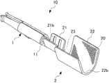
图1是表示本发明的一个实施方式的同轴电缆用接头的结构的立体图。FIG. 1 is a perspective view showing a configuration of a coaxial cable connector according to an embodiment of the present invention.
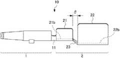
图2是表示上述实施方式的同轴电缆用接头的主视图。Fig. 2 is a front view showing the coaxial cable connector of the above embodiment.
图3A是表示上述实施方式的同轴电缆用接头的结构的立体图,是将同轴电缆用接头压接到同轴电缆的终端上之前的状态图。3A is a perspective view showing the configuration of the coaxial cable connector according to the above-mentioned embodiment, and is a state view before crimping the coaxial cable connector to the terminal of the coaxial cable.
图3B是表示上述实施方式的同轴电缆用接头的结构的立体图,是将同轴电缆用接头压接到同轴电缆的终端上之后的状态图。3B is a perspective view showing the structure of the coaxial cable connector according to the above-mentioned embodiment, and is a state view after the coaxial cable connector is crimped to the terminal of the coaxial cable.
图4的(A)是表示上述实施方式的同轴电缆用接头的主视图,是将同轴电缆用接头压接到同轴电缆的终端上之前的状态图;图4的(B)是表示上述实施方式的同轴电缆用接头的主视图,是将同轴电缆用接头压接到同轴电缆的终端上、并去掉了结合带后的状态图。(A) of Fig. 4 is a front view showing the joint for coaxial cable of the above-mentioned embodiment, and is a state view before the joint for coaxial cable is crimped on the terminal of the coaxial cable; (B) of Fig. 4 is a view showing The front view of the coaxial cable connector of the above-mentioned embodiment is a state view after the coaxial cable connector is crimped to the terminal of the coaxial cable and the bonding tape is removed.
图5A~5E是分别表示本发明的一个实施方式的同轴电缆的终端的处理步骤的图。5A to 5E are diagrams each showing a processing procedure of a termination of a coaxial cable according to an embodiment of the present invention.
图6A及图6B是分别用于说明套管的端面与插座(电介质筒)的端面之间的距离发生变动时的问题的、连接了插座与插头后的状态的主视图。6A and 6B are front views of a state where a socket and a plug are connected, for explaining problems when the distance between the end surface of the ferrule and the end surface of the socket (dielectric cylinder) varies, respectively.
符号说明Symbol Description
1:接头部;1: joint part;
2:接线部;2: wiring part;
9:同轴电缆;9: coaxial cable;
9a:内部导体;9a: inner conductor;
9b:电介质;9b: Dielectric;
9c:编织线;9c: braided wire;
9d:包层(sheath);9d: cladding (sheath);
10:第1接头(同轴电缆用接头);10: The first connector (connector for coaxial cable);
21:导体筒;21: conductor barrel;
21b:U字状底部(导体筒的U字状底部);21b: U-shaped bottom (U-shaped bottom of the conductor cylinder);
22:开口式压接筒(open crimp barrel);22: open crimp barrel (open crimp barrel);
22b:U字状底部(开口式压接筒的U字状底部);22b: U-shaped bottom (U-shaped bottom of the open crimping barrel);
23:结合带。23: Combined belt.
具体实施方式Detailed ways
在本发明中,压接同轴电缆的内部导体的内部导体用接头与压接同轴电缆的电介质的开口式压接筒构成为一体。当该开口式压接筒被压接在同轴电缆的电介质上之后,覆盖上编织线,在被压接了编织线时,该开口式压接筒作为保护电介质的套管发挥功能,以这种方式将所压接的套管与内部导体用接头隔离。根据如上所述的结构,能够解决上述问题。以下,参照附图来说明用于实施本发明的最佳方式。In the present invention, the inner conductor joint for crimping the inner conductor of the coaxial cable and the open-type crimping barrel for crimping the dielectric of the coaxial cable are integrally formed. After the open-type crimping barrel is crimped on the dielectric of the coaxial cable, the braided wire is covered. When the braided wire is crimped, the open-type crimping barrel functions as a sleeve for protecting the dielectric. One way is to isolate the crimped bushing from the inner conductor with a joint. According to the configuration as described above, the above-mentioned problems can be solved. Hereinafter, the best mode for carrying out the present invention will be described with reference to the drawings.
[同轴电缆用接头的结构][Structure of connector for coaxial cable]
首先,说明本发明的一个实施方式的同轴电缆用接头的结构。图1是表示本发明的一个实施方式的同轴电缆用接头的结构的立体图。图2是表示上述实施方式的同轴电缆用接头的主视图。First, the structure of a joint for a coaxial cable according to an embodiment of the present invention will be described. FIG. 1 is a perspective view showing a configuration of a coaxial cable connector according to an embodiment of the present invention. Fig. 2 is a front view showing the coaxial cable connector of the above embodiment.
图3A、3B是分别表示上述实施方式的同轴电缆用接头的结构的立体图,图3A是将同轴电缆用接头压接到同轴电缆的终端上之前的状态图,图3B是将同轴电缆用接头压接到同轴电缆的终端上之后的状态图。3A and 3B are perspective views respectively showing the structure of the coaxial cable connector of the above-mentioned embodiment. FIG. 3A is a state view before crimping the coaxial cable connector to the terminal of the coaxial cable. Diagram of the state after the cable has been crimped onto the end of the coaxial cable with a connector.
图4的(A)、(B)是分别表示上述实施方式的同轴电缆用接头的主视图,图4的(A)是将同轴电缆用接头压接到同轴电缆的终端上之前的状态图,图4的(B)是将同轴电缆用接头压接到同轴电缆的终端上、并且去掉了结合带后的状态图。(A) and (B) of FIG. 4 are front views respectively showing the coaxial cable connector of the above-mentioned embodiment, and FIG. State diagram, FIG. 4(B) is a state diagram after crimping the connector for the coaxial cable to the terminal of the coaxial cable and removing the bonding tape.
参照图1至图4的(A)、(B),本发明的一个实施方式的同轴电缆用接头10被安装在同轴电缆9的终端上。即,既包含机械地连接同轴电缆用接头(以下称为第1接头)10与同轴电缆9的方式,又包含将同轴电缆用接头10与同轴电缆9电连接的方式。同轴电缆9具有内部导体9a、电介质9b、编织线9c以及包层9d。内部导体9a被配置于同轴电缆9的中心部。电介质9b覆盖内部导体9a。编织线9c覆盖电介质9b。包层9d覆盖编织线9c。另外,在图3A、3B以及图4的(A)、(B)中,以使编织线9c向包层9d侧翻折后的状态示出了同轴电缆9。Referring to (A) and (B) of FIGS. 1 to 4 , a
内部导体9a也称为中心导体,可以使用单线,也可以使用由多个细线捻合而成的捻合线。电介质9b一般使用聚乙烯,但根据用途不同,有时也可以使用发泡树脂。电介质9b虽属于非导电性的绝缘体,但具有规定的相对介电常数。根据同轴电缆的截面形状以及相对介电常数,能够计算出特性阻抗。The
编织线9c是将多个细铜线编织为筒状而成的,可在规定范围内进行扩径,因此,也能够朝向包层9d侧翻折。包层9d是覆盖编织线9c的绝缘体,可使用聚氯乙烯、聚乙烯、氟树脂等绝缘材料。The
关于第1接头(同轴电缆用接头)10,优选对展开的导电性的金属板进行成形。关于展开板,如果考虑加工的容易性、导电性等,则例如优选使用铜合金,但并不限于铜合金。As for the first joint (joint for coaxial cable) 10, it is preferable to form a stretched conductive metal plate. Regarding the developed plate, for example, copper alloy is preferably used in consideration of easiness of processing, electrical conductivity, etc., but is not limited to copper alloy.
参照图1或图2,第1接头10具有接头部1和长条的接线部2。接头部1与未图示的对方侧接头相连。接线部2通过基端延伸部11从接头部1的基端部延伸出来。并且,接线部2接线在同轴电缆9的终端上(参照图3A、3B或图4的(A)、(B))。Referring to FIG. 1 or FIG. 2 , the first joint 10 has a
参照图1至图4的(A)、(B),接线部2具有:开口成U字状的导体筒21、开口成U字状的开口式压接筒22以及宽度窄的结合带23。结合带23例如是宽度比基端延伸部11窄的细带状的桥接部。导体筒21是从接头部1的基端部侧隔着基端延伸部11而配置的。另外,导体筒21能够对内部导体9a进行压接。Referring to (A) and (B) of FIG. 1 to FIG. 4 , the
参照图1至图4的(A)、(B),开口式压接筒22与导体筒21相邻。另外,开口式压接筒22能够以圆筒状地围住所露出的电介质9b的方式压接电介质9b。Referring to (A) and (B) of FIGS. 1 to 4 , the
参照图2或图4的(A),结合带23以桥接的方式结合导体筒21的端缘的一部分与相邻的开口式压接筒22的端缘的一部分。换言之,结合带23以桥接的方式结合导体筒21的U字状底部21b与开口式压接筒22的U字状底部22b。并且,结合带23形成为,在对导体筒21以及开口式压接筒22进行压接时、或进行压接之后,能够切断该结合带23的两端部,以去除该结合带23而使导体筒21与开口式压接筒22断开(参照图4的(B))。Referring to FIG. 2 or (A) of FIG. 4 , the
如图4的(B)所示,关于第1接头10,在压接了导体筒21以及开口式压接筒22且分离(除去)了结合带23之后,导体筒21作为内部导体用接头发挥功能,开口式压接筒22作为保护电介质不发生变形的套管发挥功能。As shown in FIG. 4(B), regarding the first joint 10, after the
参照图1至图4的(A)、(B),实施方式的第1接头10是对展开的导电性的金属板(未图示)进行成形而成的。接头部1构成为如下的插孔式接头:其基端部侧被成形为圆筒状,其末端部侧分支为两股,接纳对方侧的针状的插头式接头,在其内面进行电连接。但是,接头部1不限于插孔式接头。接头部1也可以设置为插头式接头,其插入到对方侧的插孔式接头之中,且在该插头式接头的外表面进行电连接。Referring to (A) and (B) of FIGS. 1 to 4 , the first joint 10 according to the embodiment is formed by forming a developed conductive metal plate (not shown). The
参照图1,开口式压接筒22优选在其内壁上设置有防止从电介质9b上脱落的防脱落单元20。防脱落单元20为了提高与电介质9b之间的摩擦系数,可以是通过滚花加工(刻痕加工)形成的钻石切割状的样子(图示了一部分),也可以是通过锯齿加工实现的具有凹凸的条纹状的样子(未图示)。Referring to FIG. 1 , the open-
另外,参照图1,防脱落单元20可包含突出于开口式压接筒22的内壁的突起(未图示),而且可包含凹入开口式压接筒22的内壁中的凹坑(未图示)。In addition, referring to FIG. 1 , the
[同轴电缆的终端处理方法][Terminal processing method of coaxial cable]
接着,对使用了实施方式的第1接头10的、同轴电缆的终端的处理步骤进行说明。图5A~5E是表示本发明的一个实施方式的同轴电缆的终端的处理步骤的图。Next, a process procedure for terminating a coaxial cable using the
首先,参照图5A,调整同轴电缆9的长度尺寸,切断同轴电缆9的终端(尺寸调整及切断步骤)。接着,从内部导体9a的端面,按预定长度阶段性地剥离电介质9b、编织线9c、以及包层9d(切断及剥离步骤)。进而,使得内部导体9a以及编织线9c露出。First, referring to FIG. 5A , the length dimension of the
接着,如图5B所示,将编织线9c翻折成覆盖包层9d(编织线翻折步骤)。Next, as shown in FIG. 5B, the
接着,如图5C所示,利用接头部1的导体筒21以及通过结合带23与该导体筒21构成为一体的开口式压接筒22,使导体筒21压接到内部导体9a上,并且将开口式压接筒22压接到电介质9b上。并且,在对导体筒21以及开口式压接筒22进行压接时、或者进行压接之后,切断结合带23的两端部,使得导体筒21与开口式压接筒22断开(压接及切断步骤)。由此,去除掉结合带23。Next, as shown in FIG. 5C, the
接着,如图5D所示,使编织线9c复原,而用编织线9c覆盖进行压接后的圆筒状的开口式压接筒22(编织线复原步骤)。Next, as shown in FIG. 5D , the
接着,如图5E所示,使用具有第1压接部31以及第2压接部32的外部导体用接头(以下称为第2接头)30,通过第1压接部31从编织线9c的上方针对已压接后的开口式压接筒22进行压接,用第2压接部32针对包层9d进行压接(外部导体用接头安装步骤)。Next, as shown in FIG. 5E , using a joint for an outer conductor (hereinafter referred to as a second joint) 30 having a first crimping
另外,在图5E中,第1接头10与第2接头30通过未图示的电介质筒(壳体)而相互结合。经过如上这样一系列的处理步骤,能够将具有第1接头10和第2接头30的同轴电缆用连接器连接到同轴电缆9的终端上。In addition, in FIG. 5E , the first joint 10 and the second joint 30 are coupled to each other through a dielectric cylinder (case) not shown. Through a series of processing steps as described above, the coaxial cable connector having the first joint 10 and the second joint 30 can be connected to the terminal of the
[同轴电缆用接头的作用][Functions of Coaxial Cable Connectors]
接着,说明实施方式的第1接头10的作用及効果。Next, the operation and effect of the first joint 10 of the embodiment will be described.
参照图1或图2,第1接头10通常是链接状接头,其中,开口式压接筒22与带板状的支撑架(carrier)(未图示)链接在一起。并且,与支撑架链接在一起的第1接头10被卷绕在未图示的卷轴上。Referring to FIG. 1 or FIG. 2 , the
对于从卷轴上拉出的带支撑架的第1接头10,使用自动压接机(未图示),针对导体筒21以及开口式压接筒22进行压接(参照图5C)。然后,如图5C所示,在针对导体筒21以及开口式压接筒22进行压接时、或进行压接之后,通过自动压接机所具备的切断工具,切断结合带23的两端部。接着,将第1接头10从支撑架上切离。The
如上所述,实施方式的第1接头10适合于通过自动压接机进行压接。如果使用自动压接机,则在针对导体筒21以及开口式压接筒22进行压接时、或进行压接之后,能够直接切断结合带23的两端部。进而,能够提高线束的生产性。As described above, the first joint 10 of the embodiment is suitable for crimping with an automatic crimping machine. If an automatic crimping machine is used, both ends of the
一般而言,压接电线(包含同轴电缆)的压接接头构成为很难使导体筒与开口式压接筒分离(断开)。另一方面,参照图1或图2,实施方式的第1接头10则形成为:能够将结合着导体筒21与开口式压接筒22的结合带23的两端部切断。In general, crimp joints for crimping electric wires (including coaxial cables) are configured so that it is difficult to separate (disconnect) the conductor barrel from the open crimp barrel. On the other hand, referring to FIG. 1 or FIG. 2 , the
参照图4的(A)、(B),关于实施方式的第1接头10,在断开导体筒21与开口式压接筒22之后,开口式压接筒22以圆筒状地围住电介质9b的方式而压接电介质9b,从而该开口式压接筒22作为保护电介质9b不发生变形的套管发挥功能。Referring to (A) and (B) of FIG. 4 , regarding the
参照图4的(A)、图5C,在实施方式的第1接头10中,包含接头部1和导体筒21的内部导体用的接头与保护电介质9b不发生变形的套管构成为一体,因此,容易安装到同轴电缆9上。Referring to Fig. 4(A) and Fig. 5C, in the first joint 10 of the embodiment, the joint for the inner conductor including the
例如,在专利文献1中,构成为,分别对内部导体用接头(内导体端子20)和套管(圆筒状套管30)进行压接。相对于此,在本发明中,如图4的(A)、图5C所示,由于是同时对导体筒21(内部导体用接头)和开口式压接筒22(套管)进行压接,因此能够缩短同轴电缆9的终端处理步骤(处理时间)。For example, in
如上所述,实施方式的第1接头10能够缩短同轴电缆9的终端处理步骤(处理时间)。并且,实施方式的第1接头10有助于降低线束的制造成本。As described above, the
图6A、6B是使用与专利文献1相同的结构,连接了插座(同轴电缆用连接器)71与插头(同轴电缆用连接器)72后的状态的主视图。参照图6A,在插座71中,套管7s从外部导体用接头7b的压接部突出。并且,套管7s的端面与插座71(电介质筒7c)的端面之间的距离为“δ1”。6A and 6B are front views of a state where a receptacle (connector for a coaxial cable) 71 and a plug (connector for a coaxial cable) 72 are connected using the same structure as
另一方面,参照图6B,在插座71中,套管7s与外部导体用接头7b的压接部的端面大致一致。并且,套管7s的端面与插座71(电介质筒7c)的端面之间的距离为“δ2”。这里,满足“δ2”>“δ1”的关系。On the other hand, referring to FIG. 6B , in the
当将几GHz频带的高频信号(行波)输送(传送)到图6A、6B中所示的同轴电缆9中时,对于同轴电缆9与插座71彼此而言,存在阻抗的略微不匹配,因此会产生信号的反射(反射波)。即、电压驻波比(VSWR:Voltage Standing Wave Ratio)为“1”以上。一般而言,理想的VSWR为“1.5”以下,且实际应用中的极限为“3”以下。并且,当VSWR的值大时,在接收侧有时会发生噪音等障碍。When a high-frequency signal (traveling wave) of several GHz band is conveyed (transmitted) into the
比较图6A和图6B,当将4GHz附近的高频信号输送到同轴电缆9中时,相比于图6A状态,图6B的状态的VSWR得到改善。即、可以看出,VSWR至少取决于套管7s的端面与插座71(电介质筒7c)的端面之间的距离δ,距离δ的变动会导致VSWR不稳定。Comparing FIGS. 6A and 6B , when a high-frequency signal around 4 GHz is sent to the
因此,参照图4的(A),在实施方式的第1接头10中,导体筒21与开口式压接筒22以具有由“δ”规定的间隔距离的方式,通过结合带23而结合。Therefore, referring to FIG. 4(A), in the first joint 10 of the embodiment, the
参照图4的(B),在实施方式的第1接头10中,即使在分别针对导体筒21与开口式压接筒22进行压接之后,分离了结合带23,导体筒21与开口式压接筒22两者之间的间隔距离“δ”也会得到保持。换言之,在第1接头10中,规定了导体筒21与开口式压接筒22之间的间隔距离“δ”。Referring to FIG. 4(B), in the first joint 10 of the embodiment, even after the
如上所述,根据图4的(A)、(B),在实施方式的第1接头10中,相对于导体筒21(内部导体用接头),开口式压接筒22(套管)在电介质上的安装位置是确定的。在实施方式的第1接头10中,相对于导体筒21(内部导体用触点),能够将开口式压接筒22(套管)安装到规定位置处。因此,能够抑制作为设计值的VSWR的变动。As described above, according to (A) and (B) of FIG. 4 , in the first joint 10 of the embodiment, the open-type crimping barrel 22 (sleeve) is placed on the dielectric body with respect to the conductor barrel 21 (joint for inner conductor). The installation location on is determined. In the first joint 10 of the embodiment, the open-type crimping barrel 22 (sleeve) can be attached at a predetermined position with respect to the conductor barrel 21 (contact for inner conductor). Therefore, fluctuations in VSWR, which is a design value, can be suppressed.
另外,参照图1,开口式压接筒22在内壁上具有通过滚花加工等形成的防止从电介质9b上脱落的防脱落单元20。因此,在针对开口式压接筒22进行压接之后,能够防止开口式压接筒22(套管)从电介质9b上脱落。即、在相对于导体筒21(内部导体用接头)、确定了开口式压接筒22(套管)在电介质上的安装位置之后,其位置关系不容易发生变动。In addition, referring to FIG. 1 , the open-
根据上述实施方式,在本发明的同轴电缆用接头中,包含接头部和导体筒的内部导体用的接头与保护电介质不发生变形的套管(对开口式压接筒进行压接之后的套管)构成为一体。由此,能够提高安装到同轴电缆上的容易性、可靠性以及精度中的至少一项。而且,本发明的同轴电缆用接头有助于同轴电缆的终端处理步骤(处理时间)的缩短以及线束的制造成本的降低。According to the above-mentioned embodiment, in the joint for coaxial cable of the present invention, the joint for the inner conductor including the joint part and the conductor barrel and the sleeve for protecting the dielectric from deformation (the sleeve after crimping the open crimping sleeve) tube) form a single unit. As a result, at least one of ease of attachment to the coaxial cable, reliability, and accuracy can be improved. Furthermore, the joint for a coaxial cable of the present invention contributes to shortening of a coaxial cable terminal processing step (processing time) and reduction of manufacturing cost of a wire harness.
Claims (5)
Applications Claiming Priority (2)
| Application Number | Priority Date | Filing Date | Title |
|---|---|---|---|
| JP2010143093AJP2012009229A (en) | 2010-06-23 | 2010-06-23 | Contact for coaxial cable and terminal processing method |
| JP2010-143093 | 2010-06-23 |
Publications (2)
| Publication Number | Publication Date |
|---|---|
| CN102394396Atrue CN102394396A (en) | 2012-03-28 |
| CN102394396B CN102394396B (en) | 2015-07-15 |
Family
ID=45352958
Family Applications (1)
| Application Number | Title | Priority Date | Filing Date |
|---|---|---|---|
| CN201110168486.6AExpired - Fee RelatedCN102394396B (en) | 2010-06-23 | 2011-06-21 | Contact for coaxial cable and end processing method for coaxial cable |
Country Status (3)
| Country | Link |
|---|---|
| US (1) | US8277249B2 (en) |
| JP (1) | JP2012009229A (en) |
| CN (1) | CN102394396B (en) |
Cited By (6)
| Publication number | Priority date | Publication date | Assignee | Title |
|---|---|---|---|---|
| CN103515795A (en)* | 2012-06-20 | 2014-01-15 | 矢崎总业株式会社 | Terminal structure of electrical cable, shielded connector and terminal treatment method of electrical cable |
| CN106329274A (en)* | 2015-06-23 | 2017-01-11 | 德州职业技术学院 | Processing method of connection protection device of radio-frequency coaxial cable assembly |
| CN112636091A (en)* | 2019-09-24 | 2021-04-09 | 日本压着端子制造株式会社 | Coaxial connector |
| CN113224693A (en)* | 2020-02-06 | 2021-08-06 | 矢崎总业株式会社 | Fabric cutting apparatus and fabric cutting method |
| CN113228428A (en)* | 2018-12-28 | 2021-08-06 | 株式会社自动网络技术研究所 | Connector with a locking member |
| CN114421187A (en)* | 2022-03-07 | 2022-04-29 | 亿嘉和科技股份有限公司 | Wire harness fixing sleeve, crimping tool, crimping effect testing device and method |
Families Citing this family (17)
| Publication number | Priority date | Publication date | Assignee | Title |
|---|---|---|---|---|
| EP2809470B1 (en) | 2012-02-03 | 2020-01-15 | Milwaukee Electric Tool Corporation | Rotary hammer |
| US8991045B2 (en) | 2013-03-12 | 2015-03-31 | Delphi Technologies, Inc. | Grounding arrangement and method for a shielded cable |
| US9510491B2 (en) | 2014-02-17 | 2016-11-29 | Lear Corporation | Electromagnetic shield termination device |
| US9142895B2 (en)* | 2014-02-17 | 2015-09-22 | Tyco Electronics Corporation | Coaxial connector assembly |
| JP6409672B2 (en)* | 2015-05-14 | 2018-10-24 | 株式会社オートネットワーク技術研究所 | Electric wire module |
| TWM512225U (en)* | 2015-07-01 | 2015-11-11 | Cooler Master Technology Inc | Power supply connector and its conductive terminal |
| JP6394524B2 (en)* | 2015-07-10 | 2018-09-26 | 株式会社オートネットワーク技術研究所 | Electromagnetic shield member and wiring device with electromagnetic shield member |
| CN106469899B (en)* | 2015-08-19 | 2018-03-13 | 浙江正泰电缆有限公司 | A kind of gum cover cable water-blocking joint structure |
| US9960504B2 (en)* | 2016-01-12 | 2018-05-01 | Yazaki Corporation | Shielded connector |
| JP2017147027A (en)* | 2016-02-15 | 2017-08-24 | 住友電装株式会社 | Electrical wire with terminal fitting and method of producing electrical wire with terminal fitting |
| KR102338051B1 (en)* | 2017-09-01 | 2021-12-10 | 가부시키가이샤 무라타 세이사쿠쇼 | Coaxial Connectors and Coaxial Connectors with Coaxial Cables |
| JP6551764B1 (en) | 2018-08-07 | 2019-07-31 | Smk株式会社 | Coaxial connector |
| US10741975B2 (en)* | 2018-10-19 | 2020-08-11 | Aptiv Technologies Limited | Sheilded cable assembly and electromagnetic shield terminal assembly for same |
| DE102018127969A1 (en)* | 2018-11-08 | 2020-05-14 | Rosenberger Hochfrequenztechnik Gmbh & Co. Kg | Measuring and positioning methods as well as arrangements for the assembly of an electrical cable |
| JP7103204B2 (en)* | 2018-12-21 | 2022-07-20 | 株式会社オートネットワーク技術研究所 | Connector structure |
| JP7129010B2 (en)* | 2018-12-21 | 2022-09-01 | 株式会社オートネットワーク技術研究所 | connector structure |
| US11050168B2 (en)* | 2019-09-12 | 2021-06-29 | Lear Corporation | Crimping terminal with wire hook to loop wire |
Citations (3)
| Publication number | Priority date | Publication date | Assignee | Title |
|---|---|---|---|---|
| JPH0620747A (en)* | 1992-06-30 | 1994-01-28 | Japan Aviation Electron Ind Ltd | Connector and manufacturing method thereof |
| US6808417B2 (en)* | 2002-04-05 | 2004-10-26 | Autonetworks Technologies, Ltd. | Coaxial connector |
| JP2006302824A (en)* | 2005-04-25 | 2006-11-02 | Auto Network Gijutsu Kenkyusho:Kk | Shield connector |
Family Cites Families (13)
| Publication number | Priority date | Publication date | Assignee | Title |
|---|---|---|---|---|
| US5203079A (en) | 1991-11-13 | 1993-04-20 | Molex Incorporated | Method of terminating miniature coaxial electrical connector |
| JP2003257560A (en) | 2002-03-04 | 2003-09-12 | Auto Network Gijutsu Kenkyusho:Kk | Shield connector |
| JP3738388B2 (en) | 2002-04-24 | 2006-01-25 | 株式会社オートネットワーク技術研究所 | Coaxial connector |
| JP4096190B2 (en)* | 2003-09-16 | 2008-06-04 | 矢崎総業株式会社 | Shield terminal for coaxial cable |
| JP2005317260A (en)* | 2004-04-27 | 2005-11-10 | Tyco Electronics Amp Kk | Coaxial connector |
| FR2877150B1 (en)* | 2004-10-27 | 2007-01-19 | Radiall Sa | METHOD FOR MOUNTING AN ELECTRICAL CONNECTOR ON A COAXIAL CABLE, AND SUCH A CONNECTOR |
| JP4235185B2 (en)* | 2005-02-24 | 2009-03-11 | 矢崎総業株式会社 | Earth plate and jig for attaching coaxial cable to it |
| JP2006310135A (en) | 2005-04-28 | 2006-11-09 | Auto Network Gijutsu Kenkyusho:Kk | Shield connector and connector cable |
| JP2006318788A (en) | 2005-05-13 | 2006-11-24 | Auto Network Gijutsu Kenkyusho:Kk | Shield connector |
| US7422480B1 (en)* | 2007-04-20 | 2008-09-09 | Delphi Technologies, Inc. | Shielded electric connector and cable assembly and method for making same |
| JP2009187826A (en) | 2008-02-07 | 2009-08-20 | Autonetworks Technologies Ltd | Shield connector and sleeve member used therefor |
| JP5156467B2 (en) | 2008-04-23 | 2013-03-06 | 株式会社オートネットワーク技術研究所 | Shield connector |
| KR101502420B1 (en) | 2008-09-22 | 2015-03-25 | 삼성디스플레이 주식회사 | Light source module and display device having the same |
- 2010
- 2010-06-23JPJP2010143093Apatent/JP2012009229A/enactivePending
- 2011
- 2011-06-21CNCN201110168486.6Apatent/CN102394396B/ennot_activeExpired - Fee Related
- 2011-06-22USUS13/166,462patent/US8277249B2/ennot_activeExpired - Fee Related
Patent Citations (3)
| Publication number | Priority date | Publication date | Assignee | Title |
|---|---|---|---|---|
| JPH0620747A (en)* | 1992-06-30 | 1994-01-28 | Japan Aviation Electron Ind Ltd | Connector and manufacturing method thereof |
| US6808417B2 (en)* | 2002-04-05 | 2004-10-26 | Autonetworks Technologies, Ltd. | Coaxial connector |
| JP2006302824A (en)* | 2005-04-25 | 2006-11-02 | Auto Network Gijutsu Kenkyusho:Kk | Shield connector |
Cited By (11)
| Publication number | Priority date | Publication date | Assignee | Title |
|---|---|---|---|---|
| CN103515795A (en)* | 2012-06-20 | 2014-01-15 | 矢崎总业株式会社 | Terminal structure of electrical cable, shielded connector and terminal treatment method of electrical cable |
| CN103515795B (en)* | 2012-06-20 | 2016-01-20 | 矢崎总业株式会社 | The method of edge treatment of the end structure of cable, shielded connector and cable |
| CN106329274A (en)* | 2015-06-23 | 2017-01-11 | 德州职业技术学院 | Processing method of connection protection device of radio-frequency coaxial cable assembly |
| CN106329274B (en)* | 2015-06-23 | 2018-07-06 | 德州职业技术学院 | The processing method of the connection protective device of radio frequency co-axial cable subassembly |
| CN113228428A (en)* | 2018-12-28 | 2021-08-06 | 株式会社自动网络技术研究所 | Connector with a locking member |
| CN113228428B (en)* | 2018-12-28 | 2024-03-12 | 株式会社自动网络技术研究所 | Connector with a plurality of connectors |
| CN112636091A (en)* | 2019-09-24 | 2021-04-09 | 日本压着端子制造株式会社 | Coaxial connector |
| CN112636091B (en)* | 2019-09-24 | 2023-03-21 | 日本压着端子制造株式会社 | Coaxial connector |
| CN113224693A (en)* | 2020-02-06 | 2021-08-06 | 矢崎总业株式会社 | Fabric cutting apparatus and fabric cutting method |
| CN113224693B (en)* | 2020-02-06 | 2022-09-13 | 矢崎总业株式会社 | Braid cutting equipment and braid cutting method |
| CN114421187A (en)* | 2022-03-07 | 2022-04-29 | 亿嘉和科技股份有限公司 | Wire harness fixing sleeve, crimping tool, crimping effect testing device and method |
Also Published As
| Publication number | Publication date |
|---|---|
| US20110318960A1 (en) | 2011-12-29 |
| US8277249B2 (en) | 2012-10-02 |
| CN102394396B (en) | 2015-07-15 |
| JP2012009229A (en) | 2012-01-12 |
Similar Documents
| Publication | Publication Date | Title |
|---|---|---|
| CN102394396B (en) | Contact for coaxial cable and end processing method for coaxial cable | |
| CN101569063B (en) | shielded connector | |
| JP4926890B2 (en) | Coaxial cable terminal processing structure | |
| US7635282B2 (en) | Coaxial cable shielding terminal with improved press-clamping portion | |
| EP3379659B1 (en) | L-type inner terminal, t-type coaxial connector including the l-type inner terminal, and method for producing the l-type coaxial connector | |
| CN101926062B (en) | Coaxial connector and method for assembling coaxial connector | |
| US7291043B2 (en) | Coaxial cable, coaxial cable end-processing structure and coaxial cable shielding terminal | |
| KR20170132741A (en) | Manufacturing method of plug connector structure | |
| US20050266727A1 (en) | Coaxial cable shielding terminal | |
| JP2004319175A (en) | Coaxial cable shield terminal | |
| US6322390B1 (en) | Coaxial connector | |
| JP2006302824A (en) | Shield connector | |
| US9236666B2 (en) | Structure of connection between coaxial cable and shield terminal, and method of connection therebetween | |
| JP2003317882A (en) | Coaxial connector | |
| US12113315B2 (en) | Shield connector | |
| US7427715B2 (en) | Cable assembly and method of making the same | |
| JP4530890B2 (en) | Coaxial cable terminal processing structure and coaxial cable shield terminal | |
| JP2004055426A (en) | Electronic element built-in coaxial connector, and connection method of this connector to coaxial wire | |
| JP2006024499A (en) | Connector for coaxial cable | |
| JPH11176527A (en) | Connector connection structure | |
| KR20200029254A (en) | Wire crimping device for high voltage connector | |
| JP5171457B2 (en) | Wiring harness | |
| JP5222169B2 (en) | Shield connector | |
| JP3378751B2 (en) | Connecting terminal | |
| JPH0245976Y2 (en) |
Legal Events
| Date | Code | Title | Description |
|---|---|---|---|
| C06 | Publication | ||
| PB01 | Publication | ||
| C10 | Entry into substantive examination | ||
| SE01 | Entry into force of request for substantive examination | ||
| C14 | Grant of patent or utility model | ||
| GR01 | Patent grant | ||
| CF01 | Termination of patent right due to non-payment of annual fee | ||
| CF01 | Termination of patent right due to non-payment of annual fee | Granted publication date:20150715 Termination date:20180621 |