CN102390370B - Stereoscopic vision based emergency treatment device and method for running vehicles - Google Patents
Stereoscopic vision based emergency treatment device and method for running vehiclesDownload PDFInfo
- Publication number
- CN102390370B CN102390370BCN 201110327030CN201110327030ACN102390370BCN 102390370 BCN102390370 BCN 102390370BCN 201110327030CN201110327030CN 201110327030CN 201110327030 ACN201110327030 ACN 201110327030ACN 102390370 BCN102390370 BCN 102390370B
- Authority
- CN
- China
- Prior art keywords
- vehicle
- road
- processing unit
- central processing
- information
- Prior art date
- Legal status (The legal status is an assumption and is not a legal conclusion. Google has not performed a legal analysis and makes no representation as to the accuracy of the status listed.)
- Expired - Fee Related
Links
- 238000000034methodMethods0.000titleclaimsabstractdescription15
- 238000012545processingMethods0.000claimsabstractdescription72
- 230000000007visual effectEffects0.000claimsabstractdescription28
- 238000001514detection methodMethods0.000claimsdescription14
- 238000009434installationMethods0.000claimsdescription12
- XLYOFNOQVPJJNP-UHFFFAOYSA-NwaterSubstancesOXLYOFNOQVPJJNP-UHFFFAOYSA-N0.000claimsdescription9
- 230000003287optical effectEffects0.000claimsdescription5
- 238000004458analytical methodMethods0.000claimsdescription4
- 238000012937correctionMethods0.000claimsdescription4
- 238000000605extractionMethods0.000claimsdescription4
- 238000003384imaging methodMethods0.000claimsdescription4
- 238000004364calculation methodMethods0.000claimsdescription3
- 238000009499grossingMethods0.000claimsdescription3
- 238000005516engineering processMethods0.000description8
- 206010039203Road traffic accidentDiseases0.000description5
- 238000011160researchMethods0.000description4
- 238000010586diagramMethods0.000description3
- 230000009286beneficial effectEffects0.000description2
- 239000000446fuelSubstances0.000description2
- 239000011159matrix materialSubstances0.000description2
- 239000010705motor oilSubstances0.000description2
- 238000011161developmentMethods0.000description1
- 230000000694effectsEffects0.000description1
- 238000005265energy consumptionMethods0.000description1
- 230000004927fusionEffects0.000description1
- 231100001267hazard identificationToxicity0.000description1
- 230000010365information processingEffects0.000description1
- 230000002093peripheral effectEffects0.000description1
- 238000007781pre-processingMethods0.000description1
- 230000008054signal transmissionEffects0.000description1
- 238000012360testing methodMethods0.000description1
Images


Landscapes
- Traffic Control Systems (AREA)
Abstract
Translated fromChinese
Description
Translated fromChinese技术领域technical field
本发明涉及汽车主动安全驾驶领域,具体是基于立体视觉图像处理的车辆行驶应急处理装置及实现方法。The invention relates to the field of active and safe driving of automobiles, in particular to a vehicle driving emergency processing device and an implementation method based on stereo vision image processing.
背景技术Background technique
汽车技术的发展给交通运输和人们的生活带来了便利,但公路交通事故的发生给人民生命财产和国民经济造成了巨大的损失。为了解决车辆交通的负面影响,人们积极寻求采用高新技术来提高车辆性能,作为智能交通系统(ITS)的组成部分,车辆安全辅助系统、先进的车辆控制系统以及自动车辆驾驶系统成为了当前研究的重点。先进的车辆系统(Advanced Vehicle System)是指借助车载设备及路测、路面的电子设备来检测周围行驶环境的变化情况,进行部分或完全的自动驾驶控制以达到行车安全和增加道路通行能力的目的。The development of automobile technology has brought convenience to transportation and people's life, but the occurrence of road traffic accidents has caused huge losses to people's lives and properties and the national economy. In order to solve the negative impact of vehicle traffic, people are actively seeking to adopt high-tech to improve vehicle performance. As a component of intelligent transportation system (ITS), vehicle safety assistance system, advanced vehicle control system and automatic vehicle driving system have become the current research topics. focus. Advanced Vehicle System (Advanced Vehicle System) refers to the use of on-board equipment, road testing, and electronic equipment on the road to detect changes in the surrounding driving environment and perform partial or complete automatic driving control to achieve driving safety and increase road traffic capacity. .
目前,在探测道路障碍物的技术中,主要有激光雷达测距、微波雷达测距、超声波测距、夜间红外测距和视觉测距。激光雷达探测距离远、精度高,但受云、雨、雾等恶劣天气影响较大,且成本较高。微波雷达性能稳定,受天气影响较小,但易受电磁干扰。超声波探测原理简单、成本低,受天气影响大,适合近距离探测,常用于倒车防撞系统。红外探测一般只适合在夜间使用。视觉探测又可分为单目视觉探测和立体视觉探测,视觉成像设备尺寸小、功耗低、获取信息量大,有利于后续信号处理,单目视觉可以检测车道信息,但无法准确确定与前方被测物体的距离,立体视觉系统可以获取道路场景及场景内物体的深度信息,结合自动光圈和自动白平衡技术,可以在夜间、隧道等可视程度较低的情况下使用,因此,立体视觉在车辆运行场景探测及车辆安全驾驶领域中具有广阔的应用前景。At present, in the technology of detecting road obstacles, there are mainly laser radar ranging, microwave radar ranging, ultrasonic ranging, infrared ranging at night and visual ranging. Lidar has a long detection distance and high accuracy, but it is greatly affected by bad weather such as clouds, rain, and fog, and its cost is high. Microwave radar has stable performance and is less affected by weather, but is susceptible to electromagnetic interference. Ultrasonic detection has a simple principle, low cost, and is greatly affected by weather. It is suitable for close-range detection and is often used in reversing collision avoidance systems. Infrared detection is generally only suitable for use at night. Visual detection can be divided into monocular vision detection and stereo vision detection. The visual imaging equipment is small in size, low in power consumption, and obtains a large amount of information, which is beneficial to subsequent signal processing. The distance of the measured object, the stereo vision system can obtain the depth information of the road scene and the objects in the scene, combined with the automatic aperture and automatic white balance technology, it can be used at night and in tunnels with low visibility. Therefore, stereo vision It has broad application prospects in the field of vehicle running scene detection and vehicle safety driving.
DSP(Digital Signal Processor,数字信号处理器)芯片是专门为快速实现各种数字信号处理算法而设计的、具有特殊的结构的微处理器,以其作为核心处理器的立体视觉控制系统,能够满足系统的实时性和体积的要求,适用于各种便携、移动终端设备的数据处理单元。DSP芯片本身的结构特性和特点,使其在数据处理方面比通用CPU具有更大优势,如采用哈佛结构、流水线操作、硬件乘法器和特殊的DSP指令。通过提高DSP芯片的硬件能力和算法的执行效率,能够在提升产品整体性能的同时,降低能源消耗和产品成本,对用户产生更大的吸引力。DSP (Digital Signal Processor, digital signal processor) chip is a microprocessor with a special structure designed for the rapid realization of various digital signal processing algorithms. As the core processor of the stereo vision control system, it can meet The real-time and volume requirements of the system are suitable for data processing units of various portable and mobile terminal equipment. The structural characteristics and characteristics of the DSP chip itself make it have greater advantages than general-purpose CPUs in data processing, such as the use of Harvard structure, pipeline operations, hardware multipliers and special DSP instructions. By improving the hardware capability of the DSP chip and the execution efficiency of the algorithm, it is possible to improve the overall performance of the product while reducing energy consumption and product cost, creating greater appeal to users.
车辆运行场景中道路状况信息的获取对于驾驶员极为重要,有关资料研究表明,若在交通事故发生前1秒钟给驾驶员发出警报,则可避免90%的交通事故。因此,及时发现前方道路的障碍及危险信息,对于避免或减少交通事故的损失,挽救人员生命,具有重要意义。同时,车辆本身的机械或电路的故障也是引发交通事故的重要原因,因此,需要车辆迅速及时地感知到故障信息,降低车速,以避免事故发生。Acquisition of road condition information in vehicle operation scenarios is extremely important for drivers. Relevant research shows that if the driver is alerted 1 second before a traffic accident occurs, 90% of traffic accidents can be avoided. Therefore, timely detection of obstacles and dangerous information on the road ahead is of great significance for avoiding or reducing the loss of traffic accidents and saving people's lives. At the same time, the mechanical or circuit failure of the vehicle itself is also an important cause of traffic accidents. Therefore, it is necessary for the vehicle to sense the failure information in a timely manner and reduce the speed of the vehicle to avoid accidents.
发明内容Contents of the invention
本发明所要解决的技术问题在于针对背景技术中存在的问题,提供一种基于立体视觉的车辆行驶应急处理装置及方法,辅助驾驶员实现道路安全驾驶。The technical problem to be solved by the present invention is to provide a vehicle driving emergency processing device and method based on stereo vision to assist the driver to realize road safety driving in view of the problems existing in the background technology.
本发明为解决上述技术问题采用以下技术方案:The present invention adopts the following technical solutions for solving the problems of the technologies described above:
一种基于立体视觉的车辆行驶应急处理装置,包括双目视觉摄像单元、车载总线接口电路、中央处理单元、车辆制动控制系统和声光告警电路;其中,A vehicle driving emergency processing device based on stereo vision, comprising a binocular vision camera unit, a vehicle bus interface circuit, a central processing unit, a vehicle braking control system and an acousto-optic alarm circuit; wherein,
所述双目视觉摄像单元用于获取车辆前方道路的两路视觉图像信息,并将其传输到中央处理单元;The binocular vision camera unit is used to obtain two-way visual image information of the road ahead of the vehicle, and transmit it to the central processing unit;
所述车载总线接口电路用于将车辆内部传感器采集得到的车辆状态信息传输到中央处理单元;The vehicle-mounted bus interface circuit is used to transmit the vehicle state information collected by the vehicle internal sensor to the central processing unit;
所述中央处理单元对所述视觉图像信息进行处理后判断车辆行进方向是否存在障碍物,以及根据车辆状态信息判断车辆是否存在故障;当车辆行进方向存在障碍物或车辆存在故障时,向车辆制动控制系统及声光告警电路发出控制信号;After processing the visual image information, the central processing unit judges whether there is an obstacle in the direction of travel of the vehicle, and judges whether there is a fault in the vehicle according to the vehicle state information; The control signal is sent out by the automatic control system and the sound and light alarm circuit;
所述车辆制动控制系统用于根据中央处理单元的控制信号,将汽车制动;The vehicle braking control system is used to brake the vehicle according to the control signal of the central processing unit;
所述声光告警电路用于接收中央处理单元输出的控制信号,发出声、光告警信息。The sound and light alarm circuit is used to receive the control signal output by the central processing unit, and send out sound and light alarm information.
进一步的,本发明的基于立体视觉的车辆行驶应急处理装置,所述双目视觉摄像单元包括两台相同型号的CCD数字彩色摄像机、数字视频输出接口;其中两台CCD数字彩色摄像机分别获取车辆前方道路的视觉图像信息,然后通过数字视频输出接口发送至中央处理单元融合成立体视觉图像信息。Further, in the vehicle driving emergency processing device based on stereo vision of the present invention, the binocular vision camera unit includes two CCD digital color cameras of the same model and a digital video output interface; wherein the two CCD digital color cameras respectively capture the front of the vehicle. The visual image information of the road is then sent to the central processing unit through the digital video output interface for fusion into stereoscopic visual image information.
进一步的,本发明的基于立体视觉的车辆行驶应急处理装置,所述中央处理单元包括数字视频输入接口、DSP中央处理器、存储器、车辆传感器总线接口、车辆制动控制系统接口和告警信息输出接口;其中,Further, in the vehicle driving emergency processing device based on stereo vision of the present invention, the central processing unit includes a digital video input interface, a DSP central processing unit, a memory, a vehicle sensor bus interface, a vehicle braking control system interface, and an alarm information output interface ;in,
所述数字视频输入接口用于将两路视觉图像信息传输至DSP中央处理器;The digital video input interface is used to transmit two-way visual image information to the DSP central processing unit;
所述DSP中央处理器用于处理所述视觉图像信息,然后与存储器中存储的安全行车道路模型进行比对,计算车辆行进方向是否存在障碍物;The DSP central processor is used to process the visual image information, then compares it with the safe driving road model stored in the memory, and calculates whether there is an obstacle in the direction of travel of the vehicle;
所述车辆传感器总线接口用于传输车辆内部传感器采集得到的车辆状态信息;The vehicle sensor bus interface is used to transmit the vehicle state information collected by the vehicle internal sensors;
所述DSP中央处理器分别通过车辆制动控制系统接口和告警信息输出接口向车辆制动控制系统和声光告警电路发送控制信号。The DSP central processor sends control signals to the vehicle brake control system and the sound and light alarm circuit through the vehicle brake control system interface and the alarm information output interface respectively.
进一步的,本发明的基于立体视觉的车辆行驶应急处理装置,所述车辆制动控制系统包括节气门执行器和制动执行器,以及节气门位置传感器、制动压力传感器;其中,节气门执行器通过直流电机和第一拉线连接发动机节气门体;制动执行器通过直流电机和第二拉线连接制动踏板,所述节气门位置传感器和制动压力传感器分别将节气门位置信号、制动压力信号反馈到中央处理单元。Further, in the vehicle emergency processing device based on stereo vision of the present invention, the vehicle braking control system includes a throttle actuator and a brake actuator, as well as a throttle position sensor and a brake pressure sensor; The actuator is connected to the throttle body of the engine through the DC motor and the first cable; the brake actuator is connected to the brake pedal through the DC motor and the second cable, and the throttle position sensor and the brake pressure sensor respectively transmit the throttle position signal, brake The pressure signal is fed back to the central processing unit.
一种基于立体视觉的车辆行驶应急处理装置的工作方法,包括安装调试步骤、应急情况识别处理步骤;A working method of a vehicle driving emergency processing device based on stereo vision, including an installation and debugging step, and an emergency situation identification and processing step;
其中安装调试步骤如下:The installation and debugging steps are as follows:
步骤1:将双目视觉摄像单元采用标准立体相机布局,安装于车辆顶部或挡风玻璃后面,用于拍摄前方道路图像;Step 1: Install the binocular vision camera unit on the top of the vehicle or behind the windshield in a standard stereo camera layout to capture images of the road ahead;
步骤2:安装制动控制系统和声光告警电路,并将双目视觉摄像单元、车载总线接口电路、车辆制动控制系统和声光告警电路连接到中央处理单元;Step 2: Install the brake control system and the sound and light alarm circuit, and connect the binocular vision camera unit, the vehicle bus interface circuit, the vehicle brake control system and the sound and light alarm circuit to the central processing unit;
步骤3:确定CCD数字彩色摄像机的内部参数和外部参数以及径向畸变系数k; Step 3: Determine the internal parameters and external parameters and radial distortion coefficient k of the CCD digital color camera;
步骤4:确定道路平面方程Sr; Step 4: Determine the road plane equation Sr;
步骤5:计算安全距离Ds:Step 5: Calculate the safety distance Ds:

其中,Ds为安全距离,


步骤6:根据道路平面Sr、车辆宽度L、车辆高度H、安全距离
图像识别处理步骤为:The image recognition processing steps are:
步骤11:将两路视觉图像信息和车辆状态信息分别输入DSP中央处理器;Step 11: Input the two-way visual image information and the vehicle state information into the DSP central processing unit respectively;
步骤12:根据步骤3获得的图像径向畸变系数k,对视觉图像信息进行径向畸变校正;Step 12: Perform radial distortion correction on the visual image information according to the image radial distortion coefficientk obtained in step 3;
步骤13:对矫正后的图像进行窗口为3像素的平滑滤波;Step 13: smoothing the corrected image with a window of 3 pixels;
步骤14:对平滑滤波后的图像进行直方图均衡化,增强对比度;Step 14: performing histogram equalization on the smoothed and filtered image to enhance the contrast;
步骤15:进行匹配基元提取,获取Harris特征点;Step 15: Perform matching primitive extraction to obtain Harris feature points;
步骤16:将两路视觉图像进行特征匹配,即在左图像中的角点寻找其在右图像中对应的角点;Step 16: Perform feature matching on the two visual images, that is, find the corresponding corner point in the right image from the corner point in the left image;
步骤17:根据以下公式进行视差计算和三维重建,得到立体视场内各点的深度信息z,进而得到具体位置信息,建立实时道路场景:Step 17: Perform parallax calculation and 3D reconstruction according to the following formula to obtain the depth informationz of each point in the stereoscopic field of view, and then obtain specific location information to establish a real-time road scene:

其中B是两摄像机采用步骤1布局时的光轴基线距离,


步骤18:道路状况检测;对步骤14获得的预处理后道路图像进行灰度和纹理分析,判断道路上是否存在积水、积雪、结冰或塌陷情况;Step 18: Road condition detection; perform grayscale and texture analysis on the preprocessed road image obtained in step 14, and determine whether there is water, snow, icing or subsidence on the road;
步骤19:障碍物及危险识别;由步骤11获得的车速信息和步骤18获得的路况信息,查询存储器,得到对应的安全行车道路模型M,确定安全行车区域范围;Step 19: Obstacle and danger identification; from the vehicle speed information obtained in step 11 and the road condition information obtained in step 18, query the memory to obtain the corresponding safe driving road model M, and determine the safe driving area;
结合步骤17获得的实时道路场景,对安全行车范围内的实际路况图像进行分割,计算各物体的实际宽度


设世界坐标系原点O在道路平面Sr上的投影为


根据步骤18获得的道路状况检测结果,如果道路上存在积水、结冰、积雪或塌陷情况,且在车辆安全行车道路模型区域内,则判断其为影响行车安全的危险信息,发送控制信号至制动控制系统及声光告警电路;如果不存在障碍和危险,则返回步骤11;According to the road condition detection result obtained in step 18, if there is water, ice, snow or subsidence on the road, and it is within the safe driving road model area of the vehicle, it is judged as dangerous information affecting driving safety, and a control signal is sent Go to the brake control system and the sound and light alarm circuit; if there are no obstacles and dangers, return to step 11;
步骤20:根据车载总线传输到中央处理单元的车辆机械和电路状态信息,判断车辆本身是否存在故障或危险,如果存在,则判断其为影响行车安全的危险信息,发送控制信号至制动控制系统及声光告警电路;如果不存在,则返回步骤11。Step 20: According to the vehicle mechanical and circuit status information transmitted to the central processing unit by the vehicle bus, determine whether there is a fault or danger in the vehicle itself, and if so, determine that it is dangerous information that affects driving safety, and send a control signal to the brake control system And the sound and light alarm circuit; if it does not exist, return to step 11.
本发明采用以上技术方案具有以下有益效果:The present invention has the following beneficial effects by adopting the above technical solutions:
本发明利用双目视觉摄像单元获取车辆前方道路场景,采用基于数字信号处理器(DSP)芯片的中央处理单元,实时计算视频图像,建立道路三维场景;根据车速和路况信息,将实际道路场景与系统存储的安全行车道路模型进行对比,计算安全行车区域内是否存在障碍或者危险,发现障碍或者危险时,启动车辆制动系统,降低车速,并向驾驶员发出声光告警信息。同时,中央处理单元通过车内总线连接车辆传感器,检测车辆的状态信息,当车辆本身发生机械或者电路故障时,启动制动系统,降低车速,发出声光告警。The invention uses a binocular vision camera unit to obtain the road scene in front of the vehicle, uses a central processing unit based on a digital signal processor (DSP) chip to calculate video images in real time, and establishes a three-dimensional road scene; according to vehicle speed and road condition information, the actual road scene and The safe driving road model stored in the system is compared to calculate whether there are obstacles or dangers in the safe driving area. When obstacles or dangers are found, the vehicle braking system is activated, the speed of the vehicle is reduced, and an audible and visual warning message is sent to the driver. At the same time, the central processing unit is connected to the vehicle sensor through the in-vehicle bus to detect the status information of the vehicle. When the vehicle itself has a mechanical or circuit failure, it will activate the braking system, reduce the speed of the vehicle, and issue an audible and visual alarm.
附图说明Description of drawings
图1是基于立体视觉的车辆行驶应急处理装置结构框图。Fig. 1 is a structural block diagram of a vehicle driving emergency processing device based on stereo vision.
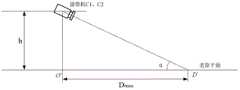
图2是双目视觉摄像单元布局俯视图。Fig. 2 is a top view of the layout of the binocular vision camera unit.
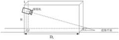
图3是双目视觉摄像单元布局侧视图。Fig. 3 is a side view of the layout of the binocular vision camera unit.
图4是安全行车道路模型图。Fig. 4 is a safe driving road model diagram.
图5是装置安装调试流程图。Figure 5 is a flow chart of device installation and commissioning.
图6是车辆运行阶段装置工作流程图。Fig. 6 is a working flow diagram of the device in the vehicle running phase.
具体实施方式Detailed ways
下面结合附图对本发明的技术方案做进一步的详细说明:Below in conjunction with accompanying drawing, technical scheme of the present invention is described in further detail:
如图1所示,所述基于立体视觉的车辆行驶应急处理装置,包括双目视觉摄像单元、车载总线接口、中央处理单元、车辆制动控制系统和声光告警电路。其中,As shown in FIG. 1 , the vehicle driving emergency processing device based on stereo vision includes a binocular vision camera unit, a vehicle bus interface, a central processing unit, a vehicle braking control system, and an acousto-optic alarm circuit. in,
所述双目视觉摄像单元包括两台相同型号的CCD数字彩色摄像机、数字视频输出接口和摄像机安装支架。两台摄像机固定在同一支架上,安装于车辆顶部或挡风玻璃后面的位置,如图2和图3所示;The binocular vision camera unit includes two CCD digital color cameras of the same model, a digital video output interface and a camera mounting bracket. The two cameras are fixed on the same bracket and installed on the top of the vehicle or behind the windshield, as shown in Figure 2 and Figure 3;
所述中央处理单元包括一个DSP中央处理器、存储器、数字视频输入接口、车辆传感器总线接口、车辆制动控制系统接口和告警信息输出接口。中央处理器包括一个高性能DSP芯片和外围电路,存储器用于数据信息的存储,该单元的供电由车内电源提供直流供电;The central processing unit includes a DSP central processing unit, a memory, a digital video input interface, a vehicle sensor bus interface, a vehicle braking control system interface and an alarm information output interface. The central processing unit includes a high-performance DSP chip and peripheral circuits, and the memory is used to store data information. The power supply of this unit is provided by the DC power supply in the car;
所述车载总线接口电路,传输车辆状态信息到中央处理单元,包括车速信息、燃油指示信息、车胎胎压信息、机油信息、水温信息、发动机故障信息和电子油门信息。目前,汽车中广泛应用CAN和LIN等总线技术,进行车内仪器设备的数据和信号传输,中央处理单元通过总线,连接车辆内部传感设备,对车辆状态进行检测;The vehicle bus interface circuit transmits vehicle status information to the central processing unit, including vehicle speed information, fuel indication information, tire pressure information, engine oil information, water temperature information, engine failure information and electronic throttle information. At present, bus technologies such as CAN and LIN are widely used in automobiles for data and signal transmission of in-vehicle instruments and equipment. The central processing unit is connected to the vehicle's internal sensor equipment through the bus to detect the vehicle status;
所述车辆制动控制系统包括节气门执行器和制动执行器,以及节气门开度和制动压力反馈电路;节气门执行器是通过直流电机和拉线连接发动机节气门体,中央处理单元输出控制信号,控制直流电机驱动机构,带动绕线器的中心轴旋转,绕线器进行正转或反转使拉绳伸长或缩短,进而控制发动机节气门开度。制动执行器是通过直流电机和拉线控制制动压力,拉线连接制动踏板,中央处理单元输出控制信号,电机带动拉线拉动制动踏板上下摆动,控制制动力的大小,在装有ABS系统(Antilock Brake System,防抱死系统)的车辆上,能够产生更好的制动效果。节气门执行器和制动执行器分别有节气门位置传感器和制动压力传感器反馈信号到中央处理单元,作为车辆制动控制系统的闭环回路,实现车辆制动的精确控制;The vehicle braking control system includes a throttle actuator and a brake actuator, and a throttle opening and a brake pressure feedback circuit; the throttle actuator is connected to the throttle body of the engine through a DC motor and a pull wire, and the central processing unit outputs The control signal controls the driving mechanism of the DC motor to drive the central axis of the winder to rotate, and the winder rotates forward or reverse to make the pull rope extend or shorten, thereby controlling the opening of the engine throttle. The brake actuator controls the braking pressure through a DC motor and a cable, the cable is connected to the brake pedal, the central processing unit outputs a control signal, and the motor drives the cable to pull the brake pedal to swing up and down to control the braking force. Antilock Brake System, anti-lock braking system) vehicles, can produce better braking effect. The throttle actuator and the brake actuator respectively have throttle position sensor and brake pressure sensor feedback signals to the central processing unit, which serve as a closed loop of the vehicle brake control system to achieve precise control of vehicle brakes;
所述声光告警电路包括语音电路和告警指示灯。语音电路存储有车辆告警提示语音,具体包括障碍告警提示和危险信息告警提示。告警指示灯分为车辆正常运行的绿色指示和行车危险时的红色闪烁指示。中央处理单元输出信号,控制声光告警电路协调工作,向驾驶员发出告警信息;The sound and light alarm circuit includes a voice circuit and an alarm indicator light. The voice circuit stores vehicle warning prompt voices, specifically including obstacle warning prompts and danger information warning prompts. The warning indicator lights are divided into green indications for normal vehicle operation and red flashing indications for dangerous driving. The central processing unit outputs signals to control the coordinating work of the sound and light warning circuit, and sends warning information to the driver;
其中,双目视觉摄像单元获取车辆前方道路场景,采用自动曝光和自动白平衡技术,获得光照条件不同场景的图像信息。中央处理单元是利用数字信号处理器(DSP),实时快速计算双目视觉图像,建立三维场景;结合存储器中存储的安全行车道路模型,与实际行车场景进行对比,计算车辆行进方向是否存在障碍或者危险,发现危险时,启动车辆制动系统,降低车速,并向驾驶员发出声光告警信息。同时,中央处理单元通过车内总线连接车辆传感器,检测车辆的状态信息,当车辆本身发生机械或者电路故障时,启动制动系统,降低车速,发出声光告警。Among them, the binocular vision camera unit acquires the road scene in front of the vehicle, and adopts automatic exposure and automatic white balance technology to obtain image information of scenes with different lighting conditions. The central processing unit uses a digital signal processor (DSP) to quickly calculate binocular vision images in real time to establish a three-dimensional scene; combined with the safe driving road model stored in the memory, it is compared with the actual driving scene to calculate whether there are obstacles or obstacles in the direction of the vehicle. Danger, when a danger is found, the vehicle brake system is activated, the vehicle speed is reduced, and an audible and visual warning message is sent to the driver. At the same time, the central processing unit is connected to the vehicle sensor through the in-vehicle bus to detect the status information of the vehicle. When the vehicle itself has a mechanical or circuit failure, it will activate the braking system, reduce the speed of the vehicle, and issue an audible and visual alarm.
本装置的安装使用分为安装调试阶段和实际运行阶段。The installation and use of this device is divided into the installation and commissioning stage and the actual operation stage.
1.如图5所示,安装调试阶段流程如下:1. As shown in Figure 5, the installation and commissioning phase process is as follows:
(1)设备安装(1) Equipment installation
设备安装包括摄像机单元、中央处理单元、制动控制系统和声光告警电路的安装,以及车载总线与中央处理单元的连接。安装完成后,给该装置各部分分别供电。Equipment installation includes the installation of camera unit, central processing unit, brake control system and sound and light alarm circuit, as well as the connection between the vehicle bus and the central processing unit. After the installation is complete, power is supplied to each part of the device separately.
(2)设备调试(2) Equipment debugging
步骤1:确定双目视觉摄像机的内部参数。包括设定摄像机的焦距f,图像坐标系的原点(u0,v0)为图像的中心像素点,每一像素在图像坐标系x轴与y轴上的物理尺寸dx和dy。取点阵图像标定模板,放置于摄像机前方,两摄像机分别拍摄点阵图像,根据模板图像的参数计算摄像机的畸变系数k(畸变系数的求解参见:范勇等,《图像几何畸变校正方法》,计算机工程与应用,2009,45(29))。Step 1: Determine the internal parameters of the binocular vision camera. It includes setting the focal lengthf of the camera, the origin (u0 ,v0 ) of the image coordinate system is the center pixel of the image, and the physical dimensionsdx anddy of each pixel on the x-axis and y-axis of the image coordinate system. Take the dot matrix image calibration template and place it in front of the camera. The two cameras take the dot matrix image respectively, and calculate the distortion coefficientk of the camera according to the parameters of the template image (for the solution of the distortion coefficient, please refer to: Fan Yong et al., "Image Geometric Distortion Correction Method", Computer Engineering and Applications, 2009, 45(29)).
步骤2:确定双目视觉摄像机的外部参数。已确定摄像机的布局为标准立体相机布局,两摄像机光轴平行,相机坐标系x轴重合,基线距离(光轴距离)为B。取摄像机平面标定模板,放置于摄像机前方,拍摄三组以上的画面,根据标定参考图像的参数计算摄像机外部参数(
步骤3:计算道路平面方程Sr。取左摄像机C1的坐标系为世界坐标系(x,y,z),最远对焦距离为Dmax。设该平面方程的表达式为Step 3: Calculate the road plane equation Sr . The coordinate system of the left camera C1 is taken as the world coordinate system (x, y, z), and the farthest focusing distance is Dmax . Let the expression of the plane equation be
Ax+By+Cz+D=0Ax+By+Cz+D=0
该平面与世界坐标系(x,y,z)的z轴的夹角为
步骤4:计算安全距离Ds。建立车速数据表,从0km/h到120km/h,以2km/h为间隔建立车速数据表vi,道路状况分为普通路况i1、雨水路况i2、积雪路况i3和结冰路况i4,不同道路状况对应车辆平均制动减速度acd不同,根据制动过程运动学分析的车辆安全距离:Step 4: Calculate the safety distance Ds . Create a speed data table, from 0km/h to 120km/h, establish a speed data table vi at intervals of 2km/h, the road conditions are divided into ordinary road conditions i1 , rainy road conditions i2 , snowy road conditions i3 and icy road conditions i4 , different road conditions correspond to different vehicle average braking deceleration acd , the vehicle safety distance according to the kinematic analysis of the braking process:
其中,Ds为安全距离,为系统和制动延迟时间,为制动后保持的安全车距。根据实际车辆行驶统计结果,路况i1对应的acd为6~8m/s2,路况i2对应的acd为5~7 m/s2,路况i3对应的acd为5~7 m/s2,路况i4对应的acd为2~5 m/s2,

步骤5:建立安全行车道路模型M,如图4所示。在道路平面Sr上建立的空间立体区域,宽度为车辆宽度L,高度为车辆高度H,长度是安全距离


2. 如图6所示,实际运行阶段装置工作流程如下:2. As shown in Figure 6, the working process of the device in the actual operation stage is as follows:
步骤6:外部数据输入。具体包括双目视觉数字视频图像的输入和车辆状态信息的输入,其中视频图像包括从摄像机C1和摄像机C2分别读入的数字视频,车辆状态信息包括车速、燃油指示、车胎胎压、机油信息、水温信息、发动机故障信息和电子油门信息。Step 6: External data input. It specifically includes the input of binocular vision digital video images and the input of vehicle status information, wherein the video images include digital videos read from cameras C1 and C2 respectively, and the vehicle status information includes vehicle speed, fuel indication, tire pressure, engine oil information, Water temperature information, engine failure information and electronic throttle information.
步骤7:视频图像预处理。根据设备调试阶段获得的图像径向畸变参数k,对两路视频图像进行径向畸变校正;对矫正后的图像进行窗口为3像素的平滑滤波;对平滑滤波后的图像进行直方图均衡化,增强对比度。Step 7: Video image preprocessing. According to the image radial distortion parameterk obtained in the equipment debugging stage, the radial distortion correction is performed on the two video images; the smoothing filter with a window of 3 pixels is performed on the corrected image; the histogram equalization is performed on the smoothed filtered image, Enhance contrast.
步骤8:匹配基元提取。匹配基元选取为图像的角点,采用具有尺度适应性的Harris尺度不变检测子,首先进行图像滤波生成图像尺度空间,计算图像中每点的Harris角点值R以及每幅图像中的最大角点值

步骤9:特征匹配,即在左图像中的角点寻找其在右图像中对应的角点;采用基于尺度不变特征匹配算法,构建Harris特征描述向量,采用最近邻算法进行匹配,即标准特征点与待匹配样本特征点的最近欧氏距离与次近欧氏距离的比值小于一定的阈值
步骤10:计算视差和三维重建。由于采用标准立体相机布局,左右图像只存在水平x轴方向的视差,不存在y轴方向的视差。设B是两摄像机采用步骤1布局时的光轴基线距离,Pl、Pr分别是空间一点P在左右像平面上的成像点,f是摄像机的焦距,
由视差信息可计算出立体视场内各点的深度信息z和位置信息(x,y,z),建立实时道路场景。The depth information z and position information (x, y, z) of each point in the stereoscopic field of view can be calculated from the disparity information, and a real-time road scene can be established.
步骤11:道路状况检测。对步骤7获得的预处理后道路图像进行灰度和纹理分析,判断道路上是否存在积水、积雪和结冰情况,如果不存在上述情况则判断为普通路况i1,有积水时判断为积水路况i2,有积雪时判断为积雪路况i3,有结冰时判断为结冰路况i4;(路况识别方法参见:Xiumin Chu,Yong Wu,《Designed on the Low Cost System Framework of Road Condition Recognition Based on Roadside Multi-sensors》,2009 Asia-Pacific Conference on Information Processing)。Step 11: Road condition detection. Carry out grayscale and texture analysis on the preprocessed road image obtained in step 7, and judge whether there is water, snow andice on the road. It is road condition i2 with accumulated water, it is judged as snow-covered road condition i3 when there is snow, and it is judged as icy road condition i4 when there is icing; Framework of Road Condition Recognition Based on Roadside Multi-sensors”, 2009 Asia-Pacific Conference on Information Processing).
步骤12:障碍物及危险识别。由步骤6获得的车速信息v和步骤11获得的路况信息i,查询存储器,得到对应的安全行车道路模型M,确定安全行车区域范围。结合步骤10获得的实时道路场景,对安全行车范围内的实际路况进行分水岭算法的分割,计算各物体的实际宽度、高度、面积


步骤13:制动与告警。当检测到车辆安全行车区域内存在障碍或危险时,中央处理单元输出控制信号,控制制动控制系统和告警电路,并且监测节气门和制动器位置,控制制动压力;告警电路向驾驶员发出语音和指示灯告警。然后,返回步骤6。Step 13: Braking and warning. When an obstacle or danger is detected in the safe driving area of the vehicle, the central processing unit outputs a control signal to control the brake control system and the alarm circuit, monitor the position of the throttle and brake, and control the brake pressure; the alarm circuit sends a voice to the driver and warning lights. Then, go back to step 6.
Claims (4)
Translated fromChinesePriority Applications (1)
| Application Number | Priority Date | Filing Date | Title |
|---|---|---|---|
| CN 201110327030CN102390370B (en) | 2011-10-25 | 2011-10-25 | Stereoscopic vision based emergency treatment device and method for running vehicles |
Applications Claiming Priority (1)
| Application Number | Priority Date | Filing Date | Title |
|---|---|---|---|
| CN 201110327030CN102390370B (en) | 2011-10-25 | 2011-10-25 | Stereoscopic vision based emergency treatment device and method for running vehicles |
Publications (2)
| Publication Number | Publication Date |
|---|---|
| CN102390370A CN102390370A (en) | 2012-03-28 |
| CN102390370Btrue CN102390370B (en) | 2013-07-03 |
Family
ID=45857798
Family Applications (1)
| Application Number | Title | Priority Date | Filing Date |
|---|---|---|---|
| CN 201110327030Expired - Fee RelatedCN102390370B (en) | 2011-10-25 | 2011-10-25 | Stereoscopic vision based emergency treatment device and method for running vehicles |
Country Status (1)
| Country | Link |
|---|---|
| CN (1) | CN102390370B (en) |
Families Citing this family (51)
| Publication number | Priority date | Publication date | Assignee | Title |
|---|---|---|---|---|
| DE102012209316A1 (en)* | 2012-06-01 | 2013-12-05 | Robert Bosch Gmbh | Method and device for processing sensor data of a stereo sensor system |
| CN102774325B (en)* | 2012-07-31 | 2014-12-10 | 西安交通大学 | Rearview reversing auxiliary system and method for forming rearview obstacle images |
| CN103010025B (en)* | 2012-12-21 | 2016-04-13 | 浙江吉利汽车研究院有限公司杭州分公司 | A kind of vehicle safety starting control method and realize the device of the method |
| CN103407407A (en)* | 2013-08-28 | 2013-11-27 | 沈阳工业大学 | Automobile safety distance warning device and method based on binocular stereo vision |
| CN103692974B (en)* | 2013-12-16 | 2015-11-25 | 广州中国科学院先进技术研究所 | A kind of vehicle driving safety method for early warning based on environmental monitoring and system |
| CN103745241A (en)* | 2014-01-14 | 2014-04-23 | 浪潮电子信息产业股份有限公司 | Intelligent driving method based on self-learning algorithm |
| CN104290730B (en)* | 2014-06-20 | 2017-08-04 | 郑州宇通客车股份有限公司 | A kind of radar applied to senior emergency braking system and video information fusion method |
| CN104401321A (en)* | 2014-11-19 | 2015-03-11 | 柳州航盛科技有限公司 | Automobile safety control system |
| CN104401304B (en)* | 2014-11-19 | 2017-10-27 | 柳州航盛科技有限公司 | Control system for automotive safety |
| CN105984447B (en)* | 2015-01-27 | 2019-01-25 | 陕西汽车集团有限责任公司 | To anticollision automatic emergency brake system and method before vehicle based on machine vision |
| CN104680816A (en)* | 2015-01-29 | 2015-06-03 | 柳州市二和汽车零部件有限公司 | Intelligent vehicle safety auxiliary control system with real-time communication |
| CN112902975B (en)* | 2015-02-10 | 2024-04-30 | 御眼视觉技术有限公司 | Autonomous vehicle navigation method, readable device, server, vehicle and system |
| US9616773B2 (en) | 2015-05-11 | 2017-04-11 | Uber Technologies, Inc. | Detecting objects within a vehicle in connection with a service |
| CN105196910B (en)* | 2015-09-15 | 2018-06-26 | 浙江吉利汽车研究院有限公司 | Safe driving assistant system and its control method under a kind of misty rain weather |
| CN105387866A (en)* | 2015-10-22 | 2016-03-09 | 广东欧珀移动通信有限公司 | Route switching method and user terminal |
| US10712160B2 (en) | 2015-12-10 | 2020-07-14 | Uatc, Llc | Vehicle traction map for autonomous vehicles |
| US9841763B1 (en) | 2015-12-16 | 2017-12-12 | Uber Technologies, Inc. | Predictive sensor array configuration system for an autonomous vehicle |
| US9840256B1 (en) | 2015-12-16 | 2017-12-12 | Uber Technologies, Inc. | Predictive sensor array configuration system for an autonomous vehicle |
| CN106954036A (en)* | 2016-01-07 | 2017-07-14 | 宁波舜宇光电信息有限公司 | Monitoring system and monitoring street lamp and its monitoring method based on 3D deep visions |
| CN107134006B (en)* | 2016-02-29 | 2020-11-24 | 株式会社理光 | Method and device for creating physical scene model and method and device for assisting driving |
| US9990548B2 (en) | 2016-03-09 | 2018-06-05 | Uber Technologies, Inc. | Traffic signal analysis system |
| CN114694113A (en)* | 2016-03-15 | 2022-07-01 | 无比视视觉技术有限公司 | Method, system and storage medium for processing road surface visual data |
| CN105913474A (en)* | 2016-04-05 | 2016-08-31 | 清华大学深圳研究生院 | Binocular three-dimensional reconstruction device and three-dimensional reconstruction method thereof, and Android application |
| US10459087B2 (en) | 2016-04-26 | 2019-10-29 | Uber Technologies, Inc. | Road registration differential GPS |
| US9672446B1 (en) | 2016-05-06 | 2017-06-06 | Uber Technologies, Inc. | Object detection for an autonomous vehicle |
| US20180005052A1 (en) | 2016-07-01 | 2018-01-04 | Uber Technologies, Inc. | Static object detection for operating autonomous vehicle |
| CN106291520A (en)* | 2016-07-14 | 2017-01-04 | 江苏大学 | A kind of DAS (Driver Assistant System) based on coded laser light and binocular vision and method |
| CN106356757B (en)* | 2016-08-11 | 2018-03-20 | 河海大学常州校区 | A kind of power circuit unmanned plane method for inspecting based on human-eye visual characteristic |
| US11094208B2 (en)* | 2016-09-30 | 2021-08-17 | The Boeing Company | Stereo camera system for collision avoidance during aircraft surface operations |
| CN106444837A (en)* | 2016-10-17 | 2017-02-22 | 北京理工大学 | Obstacle avoiding method and obstacle avoiding system for unmanned aerial vehicle |
| CN106671961A (en)* | 2017-03-02 | 2017-05-17 | 吉林大学 | Active anti-collision system based on electric automobile and control method thereof |
| CN107292263B (en)* | 2017-06-19 | 2019-01-15 | 盐城塞纳世信息技术有限公司 | A kind of motor-driven, electric vehicle automatic driving recognition system |
| CN107622510A (en)* | 2017-08-25 | 2018-01-23 | 维沃移动通信有限公司 | An information processing method and device |
| CN107609502A (en)* | 2017-09-05 | 2018-01-19 | 百度在线网络技术(北京)有限公司 | Method and apparatus for controlling automatic driving vehicle |
| CN107664598A (en)* | 2017-09-22 | 2018-02-06 | 大连海事大学 | Fibrous material tensile property measuring method based on one-dimensional digital figure correlation method |
| CN108556828A (en)* | 2018-04-26 | 2018-09-21 | 贵州大学 | A kind of autobrake system based on binocular vision |
| US11334753B2 (en) | 2018-04-30 | 2022-05-17 | Uatc, Llc | Traffic signal state classification for autonomous vehicles |
| WO2020013043A1 (en)* | 2018-07-13 | 2020-01-16 | Whill株式会社 | Electric mobility apparatus |
| CN109017729A (en)* | 2018-07-31 | 2018-12-18 | 南京越博动力系统股份有限公司 | A kind of vehicle braking auxiliary system and its control method |
| US11164287B2 (en)* | 2018-09-10 | 2021-11-02 | Lumileds Llc | Large LED array with reduced data management |
| CN109774840A (en)* | 2018-12-07 | 2019-05-21 | 纳恩博(北京)科技有限公司 | Control method, control device, system and the storage medium of the vehicles |
| CN109903325B (en)* | 2019-04-03 | 2021-05-11 | 杭州晶一智能科技有限公司 | Ground accurate description method based on stereoscopic vision depth information |
| CN110032193B (en)* | 2019-04-30 | 2020-07-03 | 盐城工业职业技术学院 | Intelligent tractor field obstacle avoidance control system and method |
| CN110321877B (en)* | 2019-06-04 | 2022-09-16 | 中北大学 | Trinocular rearview mirror and trinocular vision safe driving method and system |
| CN110738704A (en)* | 2019-10-29 | 2020-01-31 | 福建省汽车工业集团云度新能源汽车股份有限公司 | vehicle-mounted lens-free binocular imaging method and automobile thereof |
| CN110906937B (en)* | 2019-12-17 | 2023-06-27 | 陕西瑞特测控技术有限公司 | Navigation positioning method avoiding frozen road surface |
| CN112009383A (en)* | 2020-09-28 | 2020-12-01 | 天津职业技术师范大学(中国职业培训指导教师进修中心) | Road congestion pre-judging device, system and method |
| WO2022141294A1 (en)* | 2020-12-30 | 2022-07-07 | 深圳市大疆创新科技有限公司 | Simulation test method and system, simulator, storage medium, and program product |
| CN113561947B (en)* | 2021-07-02 | 2022-09-20 | 北京中科慧眼科技有限公司 | Automatic braking method, device and system for passenger car |
| CN113984085A (en)* | 2021-11-16 | 2022-01-28 | 华东交通大学 | Information sensing method and system for road covered by rain and snow and storage medium |
| CN117953065B (en)* | 2024-03-26 | 2024-06-11 | 新乡职业技术学院 | A field vehicle control system based on image processing |
Citations (8)
| Publication number | Priority date | Publication date | Assignee | Title |
|---|---|---|---|---|
| EP1441936B1 (en)* | 2001-10-30 | 2005-12-21 | Robert Bosch Gmbh | Device for longitudinally guiding a motor vehicle |
| CN101135558A (en)* | 2007-09-28 | 2008-03-05 | 深圳先进技术研究院 | A method and device for vehicle collision avoidance warning based on machine vision |
| EP1318042B1 (en)* | 2001-12-07 | 2008-07-30 | Hitachi Ltd. | Vehicle distance and speed control with navigation system input |
| CN201249721Y (en)* | 2008-06-23 | 2009-06-03 | 长安大学 | Vehicle lane departure prewarning device |
| CN101585318A (en)* | 2009-06-30 | 2009-11-25 | 奇瑞汽车股份有限公司 | Automatic emergency processing system of tire pressure failure and processing method thereof |
| CN201812368U (en)* | 2010-08-24 | 2011-04-27 | 清华大学 | Test setup for lane departure warning system |
| CN102069770A (en)* | 2010-12-16 | 2011-05-25 | 福州名品电子科技有限公司 | Automobile active safety control system based on binocular stereo vision and control method thereof |
| CN202271980U (en)* | 2011-10-25 | 2012-06-13 | 河海大学 | Stereoscopic-vision-based vehicle running emergency treatment device |
- 2011
- 2011-10-25CNCN 201110327030patent/CN102390370B/ennot_activeExpired - Fee Related
Patent Citations (8)
| Publication number | Priority date | Publication date | Assignee | Title |
|---|---|---|---|---|
| EP1441936B1 (en)* | 2001-10-30 | 2005-12-21 | Robert Bosch Gmbh | Device for longitudinally guiding a motor vehicle |
| EP1318042B1 (en)* | 2001-12-07 | 2008-07-30 | Hitachi Ltd. | Vehicle distance and speed control with navigation system input |
| CN101135558A (en)* | 2007-09-28 | 2008-03-05 | 深圳先进技术研究院 | A method and device for vehicle collision avoidance warning based on machine vision |
| CN201249721Y (en)* | 2008-06-23 | 2009-06-03 | 长安大学 | Vehicle lane departure prewarning device |
| CN101585318A (en)* | 2009-06-30 | 2009-11-25 | 奇瑞汽车股份有限公司 | Automatic emergency processing system of tire pressure failure and processing method thereof |
| CN201812368U (en)* | 2010-08-24 | 2011-04-27 | 清华大学 | Test setup for lane departure warning system |
| CN102069770A (en)* | 2010-12-16 | 2011-05-25 | 福州名品电子科技有限公司 | Automobile active safety control system based on binocular stereo vision and control method thereof |
| CN202271980U (en)* | 2011-10-25 | 2012-06-13 | 河海大学 | Stereoscopic-vision-based vehicle running emergency treatment device |
Non-Patent Citations (4)
| Title |
|---|
| 伍宗富.基于图像识别的汽车智能防撞系统研究与实现.《机械与电子》.2008,(第9期), |
| 基于DSP的智能车辆防撞系统研究;陈善勇等;《自动化技术与应用》;20050131;第24卷(第1期);第58页左栏倒数第1段,图1* |
| 基于图像识别的汽车智能防撞系统研究与实现;伍宗富;《机械与电子》;20080930(第9期);第56-60页* |
| 陈善勇等.基于DSP的智能车辆防撞系统研究.《自动化技术与应用》.2005,第24卷(第1期), |
Also Published As
| Publication number | Publication date |
|---|---|
| CN102390370A (en) | 2012-03-28 |
Similar Documents
| Publication | Publication Date | Title |
|---|---|---|
| CN102390370B (en) | Stereoscopic vision based emergency treatment device and method for running vehicles | |
| CN202271980U (en) | Stereoscopic-vision-based vehicle running emergency treatment device | |
| CN111010532B (en) | Vehicle-mounted machine vision system based on multi-focal-distance camera group | |
| CN110444014A (en) | The anti-method for early warning that knocks into the back based on reversed ST-MRF vehicle tracking algorithm | |
| CN111994068B (en) | Intelligent driving automobile control system based on intelligent tire touch perception | |
| CN103072537B (en) | Automotive collision avoidance safety protecting method based on infrared image processing | |
| US20140063248A1 (en) | Vehicle periphery monitoring device | |
| CN202169907U (en) | Device used for identifying environment outside vehicle | |
| CN104802710B (en) | A kind of intelligent automobile reversing aid system and householder method | |
| CN101549691A (en) | Vehicle intelligent device for automatically identifying road pit or obstruction | |
| CN102632839A (en) | Vehicle-mounted blind area early warning system and method based on rear view image cognition | |
| WO2021164463A1 (en) | Detection method and apparatus, storage medium | |
| CN110816527A (en) | A vehicle night vision security method and system | |
| CN115320584A (en) | Vehicle remote driving assistance method and remote driving system considering obstacle early warning | |
| CN103692974B (en) | A kind of vehicle driving safety method for early warning based on environmental monitoring and system | |
| CN113808418B (en) | Road condition information display system, method, vehicle, computer device and storage medium | |
| CN111650944A (en) | Auto-driving parallel control method for improving driving safety | |
| CN108528337A (en) | A kind of lubrication groove difference intelligent early-warning system and method for early warning based on video projection | |
| CN114155257A (en) | Industrial vehicle early warning and obstacle avoidance method and system based on binocular camera | |
| CN207607439U (en) | A kind of vehicle collision avoidance prior-warning device based on binocular camera | |
| CN205800930U (en) | Automotive safety DAS (Driver Assistant System) based on monocular camera machine vision | |
| CN211578054U (en) | Ghost probe anti-collision early warning system in Internet of things environment | |
| CN202863435U (en) | Automatic control device for vehicle turning | |
| CN204596166U (en) | Vehicle intelligent Traffic Sign Recognition System | |
| CN114715152A (en) | Vehicle formation method based on perception safety redundancy |
Legal Events
| Date | Code | Title | Description |
|---|---|---|---|
| C06 | Publication | ||
| PB01 | Publication | ||
| C10 | Entry into substantive examination | ||
| SE01 | Entry into force of request for substantive examination | ||
| C14 | Grant of patent or utility model | ||
| GR01 | Patent grant | ||
| CF01 | Termination of patent right due to non-payment of annual fee | Granted publication date:20130703 | |
| CF01 | Termination of patent right due to non-payment of annual fee |