CN102388512A - Cascaded Raman fiber laser system based on filter fiber - Google Patents
Cascaded Raman fiber laser system based on filter fiberDownload PDFInfo
- Publication number
- CN102388512A CN102388512ACN2010800101553ACN201080010155ACN102388512ACN 102388512 ACN102388512 ACN 102388512ACN 2010800101553 ACN2010800101553 ACN 2010800101553ACN 201080010155 ACN201080010155 ACN 201080010155ACN 102388512 ACN102388512 ACN 102388512A
- Authority
- CN
- China
- Prior art keywords
- wavelength
- optical fiber
- raman
- filter
- output
- Prior art date
- Legal status (The legal status is an assumption and is not a legal conclusion. Google has not performed a legal analysis and makes no representation as to the accuracy of the status listed.)
- Granted
Links
Images


Classifications
- H—ELECTRICITY
- H01—ELECTRIC ELEMENTS
- H01S—DEVICES USING THE PROCESS OF LIGHT AMPLIFICATION BY STIMULATED EMISSION OF RADIATION [LASER] TO AMPLIFY OR GENERATE LIGHT; DEVICES USING STIMULATED EMISSION OF ELECTROMAGNETIC RADIATION IN WAVE RANGES OTHER THAN OPTICAL
- H01S3/00—Lasers, i.e. devices using stimulated emission of electromagnetic radiation in the infrared, visible or ultraviolet wave range
- H01S3/05—Construction or shape of optical resonators; Accommodation of active medium therein; Shape of active medium
- H01S3/06—Construction or shape of active medium
- H01S3/063—Waveguide lasers, i.e. whereby the dimensions of the waveguide are of the order of the light wavelength
- H01S3/067—Fibre lasers
- H01S3/06708—Constructional details of the fibre, e.g. compositions, cross-section, shape or tapering
- H01S3/06729—Peculiar transverse fibre profile
- H01S3/06733—Fibre having more than one cladding
- H—ELECTRICITY
- H01—ELECTRIC ELEMENTS
- H01S—DEVICES USING THE PROCESS OF LIGHT AMPLIFICATION BY STIMULATED EMISSION OF RADIATION [LASER] TO AMPLIFY OR GENERATE LIGHT; DEVICES USING STIMULATED EMISSION OF ELECTROMAGNETIC RADIATION IN WAVE RANGES OTHER THAN OPTICAL
- H01S3/00—Lasers, i.e. devices using stimulated emission of electromagnetic radiation in the infrared, visible or ultraviolet wave range
- H01S3/05—Construction or shape of optical resonators; Accommodation of active medium therein; Shape of active medium
- H01S3/06—Construction or shape of active medium
- H01S3/063—Waveguide lasers, i.e. whereby the dimensions of the waveguide are of the order of the light wavelength
- H01S3/067—Fibre lasers
- H01S3/0675—Resonators including a grating structure, e.g. distributed Bragg reflectors [DBR] or distributed feedback [DFB] fibre lasers
- H—ELECTRICITY
- H01—ELECTRIC ELEMENTS
- H01S—DEVICES USING THE PROCESS OF LIGHT AMPLIFICATION BY STIMULATED EMISSION OF RADIATION [LASER] TO AMPLIFY OR GENERATE LIGHT; DEVICES USING STIMULATED EMISSION OF ELECTROMAGNETIC RADIATION IN WAVE RANGES OTHER THAN OPTICAL
- H01S3/00—Lasers, i.e. devices using stimulated emission of electromagnetic radiation in the infrared, visible or ultraviolet wave range
- H01S3/09—Processes or apparatus for excitation, e.g. pumping
- H01S3/091—Processes or apparatus for excitation, e.g. pumping using optical pumping
- H01S3/094—Processes or apparatus for excitation, e.g. pumping using optical pumping by coherent light
- H01S3/094042—Processes or apparatus for excitation, e.g. pumping using optical pumping by coherent light of a fibre laser
- H01S3/094046—Processes or apparatus for excitation, e.g. pumping using optical pumping by coherent light of a fibre laser of a Raman fibre laser
- H—ELECTRICITY
- H01—ELECTRIC ELEMENTS
- H01S—DEVICES USING THE PROCESS OF LIGHT AMPLIFICATION BY STIMULATED EMISSION OF RADIATION [LASER] TO AMPLIFY OR GENERATE LIGHT; DEVICES USING STIMULATED EMISSION OF ELECTROMAGNETIC RADIATION IN WAVE RANGES OTHER THAN OPTICAL
- H01S3/00—Lasers, i.e. devices using stimulated emission of electromagnetic radiation in the infrared, visible or ultraviolet wave range
- H01S3/30—Lasers, i.e. devices using stimulated emission of electromagnetic radiation in the infrared, visible or ultraviolet wave range using scattering effects, e.g. stimulated Brillouin or Raman effects
- H01S3/302—Lasers, i.e. devices using stimulated emission of electromagnetic radiation in the infrared, visible or ultraviolet wave range using scattering effects, e.g. stimulated Brillouin or Raman effects in an optical fibre
- H—ELECTRICITY
- H01—ELECTRIC ELEMENTS
- H01S—DEVICES USING THE PROCESS OF LIGHT AMPLIFICATION BY STIMULATED EMISSION OF RADIATION [LASER] TO AMPLIFY OR GENERATE LIGHT; DEVICES USING STIMULATED EMISSION OF ELECTROMAGNETIC RADIATION IN WAVE RANGES OTHER THAN OPTICAL
- H01S3/00—Lasers, i.e. devices using stimulated emission of electromagnetic radiation in the infrared, visible or ultraviolet wave range
- H01S3/005—Optical devices external to the laser cavity, specially adapted for lasers, e.g. for homogenisation of the beam or for manipulating laser pulses, e.g. pulse shaping
- H01S3/0064—Anti-reflection devices, e.g. optical isolaters
- H—ELECTRICITY
- H01—ELECTRIC ELEMENTS
- H01S—DEVICES USING THE PROCESS OF LIGHT AMPLIFICATION BY STIMULATED EMISSION OF RADIATION [LASER] TO AMPLIFY OR GENERATE LIGHT; DEVICES USING STIMULATED EMISSION OF ELECTROMAGNETIC RADIATION IN WAVE RANGES OTHER THAN OPTICAL
- H01S3/00—Lasers, i.e. devices using stimulated emission of electromagnetic radiation in the infrared, visible or ultraviolet wave range
- H01S3/005—Optical devices external to the laser cavity, specially adapted for lasers, e.g. for homogenisation of the beam or for manipulating laser pulses, e.g. pulse shaping
- H01S3/0078—Frequency filtering
- H—ELECTRICITY
- H01—ELECTRIC ELEMENTS
- H01S—DEVICES USING THE PROCESS OF LIGHT AMPLIFICATION BY STIMULATED EMISSION OF RADIATION [LASER] TO AMPLIFY OR GENERATE LIGHT; DEVICES USING STIMULATED EMISSION OF ELECTROMAGNETIC RADIATION IN WAVE RANGES OTHER THAN OPTICAL
- H01S3/00—Lasers, i.e. devices using stimulated emission of electromagnetic radiation in the infrared, visible or ultraviolet wave range
- H01S3/05—Construction or shape of optical resonators; Accommodation of active medium therein; Shape of active medium
- H01S3/06—Construction or shape of active medium
- H01S3/063—Waveguide lasers, i.e. whereby the dimensions of the waveguide are of the order of the light wavelength
- H01S3/067—Fibre lasers
- H01S3/06708—Constructional details of the fibre, e.g. compositions, cross-section, shape or tapering
- H—ELECTRICITY
- H01—ELECTRIC ELEMENTS
- H01S—DEVICES USING THE PROCESS OF LIGHT AMPLIFICATION BY STIMULATED EMISSION OF RADIATION [LASER] TO AMPLIFY OR GENERATE LIGHT; DEVICES USING STIMULATED EMISSION OF ELECTROMAGNETIC RADIATION IN WAVE RANGES OTHER THAN OPTICAL
- H01S3/00—Lasers, i.e. devices using stimulated emission of electromagnetic radiation in the infrared, visible or ultraviolet wave range
- H01S3/05—Construction or shape of optical resonators; Accommodation of active medium therein; Shape of active medium
- H01S3/06—Construction or shape of active medium
- H01S3/063—Waveguide lasers, i.e. whereby the dimensions of the waveguide are of the order of the light wavelength
- H01S3/067—Fibre lasers
- H01S3/06754—Fibre amplifiers
- H01S3/06758—Tandem amplifiers
- H—ELECTRICITY
- H01—ELECTRIC ELEMENTS
- H01S—DEVICES USING THE PROCESS OF LIGHT AMPLIFICATION BY STIMULATED EMISSION OF RADIATION [LASER] TO AMPLIFY OR GENERATE LIGHT; DEVICES USING STIMULATED EMISSION OF ELECTROMAGNETIC RADIATION IN WAVE RANGES OTHER THAN OPTICAL
- H01S3/00—Lasers, i.e. devices using stimulated emission of electromagnetic radiation in the infrared, visible or ultraviolet wave range
- H01S3/05—Construction or shape of optical resonators; Accommodation of active medium therein; Shape of active medium
- H01S3/06—Construction or shape of active medium
- H01S3/07—Construction or shape of active medium consisting of a plurality of parts, e.g. segments
- H—ELECTRICITY
- H01—ELECTRIC ELEMENTS
- H01S—DEVICES USING THE PROCESS OF LIGHT AMPLIFICATION BY STIMULATED EMISSION OF RADIATION [LASER] TO AMPLIFY OR GENERATE LIGHT; DEVICES USING STIMULATED EMISSION OF ELECTROMAGNETIC RADIATION IN WAVE RANGES OTHER THAN OPTICAL
- H01S3/00—Lasers, i.e. devices using stimulated emission of electromagnetic radiation in the infrared, visible or ultraviolet wave range
- H01S3/05—Construction or shape of optical resonators; Accommodation of active medium therein; Shape of active medium
- H01S3/08—Construction or shape of optical resonators or components thereof
- H01S3/08086—Multiple-wavelength emission
- H—ELECTRICITY
- H01—ELECTRIC ELEMENTS
- H01S—DEVICES USING THE PROCESS OF LIGHT AMPLIFICATION BY STIMULATED EMISSION OF RADIATION [LASER] TO AMPLIFY OR GENERATE LIGHT; DEVICES USING STIMULATED EMISSION OF ELECTROMAGNETIC RADIATION IN WAVE RANGES OTHER THAN OPTICAL
- H01S3/00—Lasers, i.e. devices using stimulated emission of electromagnetic radiation in the infrared, visible or ultraviolet wave range
- H01S3/09—Processes or apparatus for excitation, e.g. pumping
- H01S3/091—Processes or apparatus for excitation, e.g. pumping using optical pumping
- H01S3/094—Processes or apparatus for excitation, e.g. pumping using optical pumping by coherent light
- H01S3/094003—Processes or apparatus for excitation, e.g. pumping using optical pumping by coherent light the pumped medium being a fibre
- H01S3/094007—Cladding pumping, i.e. pump light propagating in a clad surrounding the active core
- H—ELECTRICITY
- H01—ELECTRIC ELEMENTS
- H01S—DEVICES USING THE PROCESS OF LIGHT AMPLIFICATION BY STIMULATED EMISSION OF RADIATION [LASER] TO AMPLIFY OR GENERATE LIGHT; DEVICES USING STIMULATED EMISSION OF ELECTROMAGNETIC RADIATION IN WAVE RANGES OTHER THAN OPTICAL
- H01S3/00—Lasers, i.e. devices using stimulated emission of electromagnetic radiation in the infrared, visible or ultraviolet wave range
- H01S3/09—Processes or apparatus for excitation, e.g. pumping
- H01S3/091—Processes or apparatus for excitation, e.g. pumping using optical pumping
- H01S3/094—Processes or apparatus for excitation, e.g. pumping using optical pumping by coherent light
- H01S3/09408—Pump redundancy
- H—ELECTRICITY
- H01—ELECTRIC ELEMENTS
- H01S—DEVICES USING THE PROCESS OF LIGHT AMPLIFICATION BY STIMULATED EMISSION OF RADIATION [LASER] TO AMPLIFY OR GENERATE LIGHT; DEVICES USING STIMULATED EMISSION OF ELECTROMAGNETIC RADIATION IN WAVE RANGES OTHER THAN OPTICAL
- H01S3/00—Lasers, i.e. devices using stimulated emission of electromagnetic radiation in the infrared, visible or ultraviolet wave range
- H01S3/09—Processes or apparatus for excitation, e.g. pumping
- H01S3/091—Processes or apparatus for excitation, e.g. pumping using optical pumping
- H01S3/094—Processes or apparatus for excitation, e.g. pumping using optical pumping by coherent light
- H01S3/094084—Processes or apparatus for excitation, e.g. pumping using optical pumping by coherent light with pump light recycling, i.e. with reinjection of the unused pump light, e.g. by reflectors or circulators
- H—ELECTRICITY
- H01—ELECTRIC ELEMENTS
- H01S—DEVICES USING THE PROCESS OF LIGHT AMPLIFICATION BY STIMULATED EMISSION OF RADIATION [LASER] TO AMPLIFY OR GENERATE LIGHT; DEVICES USING STIMULATED EMISSION OF ELECTROMAGNETIC RADIATION IN WAVE RANGES OTHER THAN OPTICAL
- H01S3/00—Lasers, i.e. devices using stimulated emission of electromagnetic radiation in the infrared, visible or ultraviolet wave range
- H01S3/09—Processes or apparatus for excitation, e.g. pumping
- H01S3/091—Processes or apparatus for excitation, e.g. pumping using optical pumping
- H01S3/094—Processes or apparatus for excitation, e.g. pumping using optical pumping by coherent light
- H01S3/0941—Processes or apparatus for excitation, e.g. pumping using optical pumping by coherent light of a laser diode
- H01S3/09415—Processes or apparatus for excitation, e.g. pumping using optical pumping by coherent light of a laser diode the pumping beam being parallel to the lasing mode of the pumped medium, e.g. end-pumping
- H—ELECTRICITY
- H01—ELECTRIC ELEMENTS
- H01S—DEVICES USING THE PROCESS OF LIGHT AMPLIFICATION BY STIMULATED EMISSION OF RADIATION [LASER] TO AMPLIFY OR GENERATE LIGHT; DEVICES USING STIMULATED EMISSION OF ELECTROMAGNETIC RADIATION IN WAVE RANGES OTHER THAN OPTICAL
- H01S3/00—Lasers, i.e. devices using stimulated emission of electromagnetic radiation in the infrared, visible or ultraviolet wave range
- H01S3/14—Lasers, i.e. devices using stimulated emission of electromagnetic radiation in the infrared, visible or ultraviolet wave range characterised by the material used as the active medium
- H01S3/16—Solid materials
- H01S3/1601—Solid materials characterised by an active (lasing) ion
- H01S3/1603—Solid materials characterised by an active (lasing) ion rare earth
- H01S3/1608—Solid materials characterised by an active (lasing) ion rare earth erbium
- H—ELECTRICITY
- H01—ELECTRIC ELEMENTS
- H01S—DEVICES USING THE PROCESS OF LIGHT AMPLIFICATION BY STIMULATED EMISSION OF RADIATION [LASER] TO AMPLIFY OR GENERATE LIGHT; DEVICES USING STIMULATED EMISSION OF ELECTROMAGNETIC RADIATION IN WAVE RANGES OTHER THAN OPTICAL
- H01S3/00—Lasers, i.e. devices using stimulated emission of electromagnetic radiation in the infrared, visible or ultraviolet wave range
- H01S3/14—Lasers, i.e. devices using stimulated emission of electromagnetic radiation in the infrared, visible or ultraviolet wave range characterised by the material used as the active medium
- H01S3/16—Solid materials
- H01S3/1601—Solid materials characterised by an active (lasing) ion
- H01S3/1603—Solid materials characterised by an active (lasing) ion rare earth
- H01S3/1618—Solid materials characterised by an active (lasing) ion rare earth ytterbium
- H—ELECTRICITY
- H01—ELECTRIC ELEMENTS
- H01S—DEVICES USING THE PROCESS OF LIGHT AMPLIFICATION BY STIMULATED EMISSION OF RADIATION [LASER] TO AMPLIFY OR GENERATE LIGHT; DEVICES USING STIMULATED EMISSION OF ELECTROMAGNETIC RADIATION IN WAVE RANGES OTHER THAN OPTICAL
- H01S3/00—Lasers, i.e. devices using stimulated emission of electromagnetic radiation in the infrared, visible or ultraviolet wave range
- H01S3/23—Arrangements of two or more lasers not provided for in groups H01S3/02 - H01S3/22, e.g. tandem arrangements of separate active media
- H01S3/2375—Hybrid lasers
Landscapes
- Physics & Mathematics (AREA)
- Electromagnetism (AREA)
- Engineering & Computer Science (AREA)
- Plasma & Fusion (AREA)
- Optics & Photonics (AREA)
- Lasers (AREA)
- Optical Modulation, Optical Deflection, Nonlinear Optics, Optical Demodulation, Optical Logic Elements (AREA)
Abstract
Description
Translated fromChinese对相关申请的交叉引用Cross References to Related Applications
本申请要求2009年5月11日提交的61/177058号美国临时专利申请的优先权,该临时申请由本申请的受让人拥有,并且其全部内容通过引用包含于此。This application claims priority to US Provisional Patent Application No. 61/177058, filed May 11, 2009, which is owned by the assignee of the present application and is hereby incorporated by reference in its entirety.
技术领域technical field
本发明总体上涉及光纤装置和方法,并且更具体地涉及基于滤波器光纤的改进的级联拉曼光纤激光器系统。The present invention relates generally to fiber optic devices and methods, and more particularly to improved cascaded Raman fiber laser systems based on filter fibers.
背景技术Background technique
级联拉曼光纤激光器(cascaded Raman fiber laser,CRFL)是用于产生在无法获得稀土离子增益的波长下的激光输出的有用装置。CRFL提供从开始波长向选定的目标波长的逐步转换。该逐步转换是通过在适当的拉曼增益介质中一个或多个拉曼级的级联激光发射产生的。例如通过对应的一系列嵌套的串联(in-line)反射光栅对在增益介质中产生一系列嵌套的拉曼腔体。通过前面的腔体中的拉曼散射引入的相应的拉曼斯托克斯频移将该系列中的每个连续的腔体的波长与前面的腔体分离。典型地使用高功率连续波(CW)激光器(如包层泵浦的掺Yb光纤激光器)来泵浦CRFL。A cascaded Raman fiber laser (CRFL) is a useful device for generating laser output at wavelengths where rare earth ion gain is not available. CRFLs provide a stepwise transition from a starting wavelength to a selected target wavelength. This stepwise conversion is produced by cascaded lasing of one or more Raman stages in a suitable Raman gain medium. A series of nested Raman cavities are created in the gain medium, eg by a corresponding series of nested in-line reflective grating pairs. The wavelength of each successive cavity in the series is separated from the preceding cavity by a corresponding Raman-Stokes shift introduced by Raman scattering in the preceding cavity. The CRFL is typically pumped using a high power continuous wave (CW) laser such as a cladding pumped Yb-doped fiber laser.
图1是当前的CRFL系统配置20的图,在该系统中展示了在1480nm下41W功率的系统输出。单模1480nm的系统输出70适于用作用于掺铒光纤激光器(EDFL)或掺铒光纤放大器(EDFA)的纤芯泵浦的高功率泵浦。如图1中所示,系统20包括两个级:整体掺Yb光纤激光器40和级联拉曼谐振器(CRR)60。Figure 1 is a diagram of a current
在激光器40中,由在1000nm至1200nm的区域内工作的一段双包层掺Yb光纤42提供激活增益介质。在光纤42的输入端44提供高反射光栅HR1,并且在光纤42的输出端46提供输出耦合光栅OC1。高反射器件HR1、输出耦合器OC1和光纤42起到激光器腔体48的作用。由利用锥形光纤束(tapered fiber bundle)TFB1耦合到光纤42的多个泵浦50(例如多模915nm或975nm二极管激光器)向光纤42提供泵浦功率。在本示例中,激光器输出52是波长在1117nm的单模辐射。In the
激光器输出52被用于将泵浦功率输入到级联拉曼谐振器60中。谐振器60包括具有小的有效面积和正常色散的拉曼激活光纤62。正常色散防止调制不稳定性,调制不稳定性会导致在高功率时产生超连续谱。小的有效面积导致高拉曼增益,并且因此可以产生多个斯托克斯级。
在拉曼光纤的输入端64提供第一多个高反射光栅HR2-HR6,并且在拉曼光纤的输出端66提供第二多个高反射光栅HR7-HR11和输出耦合器OC2。附加的泵浦反射器件重复利用未使用的Yb辐射以增加效率。输入光栅HR2-HR6、输出光栅HR7-HR11和OC2以及拉曼光纤64提供一系列嵌套的拉曼腔体68。每个嵌套的拉曼腔体的相应波长被配置成在宽范围上产生一系列级联的斯托克斯频移,以通过一系列步骤将波长为1117nm的激光器输出增加到1480nm的目标波长。输出耦合器OC2提供1480nm的目标波长的系统输出70,该系统输出可随后被用于以基模泵浦EDFA或EDFL。At the
现有技术的系统20受到多个已知的缺点和局限的影响。The
首先,在1480nm将输出功率增加到41W时,发现必须限制谐振器60中拉曼光纤62的长度,以避免对位于1590nm的下一斯托克斯级的不希望的拉曼散射。First, when increasing the output power to 41 W at 1480 nm, it was found that the length of the Raman fiber 62 in the
此外,位于系统20中的不同波长和位置处的多个反射器件结合以产生耦合的腔体。将会看到,在1117nm的激光波长下有三个反射器件,即光栅HR1、OC1和HR7。通常这不会对在相对低功率工作的系统(例如,在1480nm下输出5W)造成问题。然而,近来,关于拉曼光纤激光器的功率调整(scaling)进行了研究。从CRR展示出上面提到的高达41W的功率水平。Furthermore, multiple reflective devices at different wavelengths and locations in the
尽管从这种系统展示出高功率,但是图1中的装置的耦合腔体的特性对长期可靠工作具有严重影响。特别地,耦合腔体能够使该系统变得不稳定,并且产生相当高峰值功率的脉冲,从而损坏部件。特别发现激光器的高反射器件HR1是该系统中的薄弱环节,推测起来,这是由于通过它传播的高功率造成的,并且还观察到在包括例如使用系统20泵浦掺铒光纤激光器或放大器的各种条件下激光器的高反射器件HR1失效。另外,在拉曼激光器中产生的中间斯托克斯级的光可能传播回Yb放大器中并回到泵浦二极管,造成它们失效。此外,在第一斯托克斯频移下的光仍在Yb的增益带宽内,并且在到达二极管之前被放大。这显然也是有害的。Although high power is exhibited from such a system, the characteristics of the coupled cavity of the device in Fig. 1 have serious implications for long-term reliable operation. In particular, coupled cavities can destabilize the system and generate pulses of rather high peak power that can damage components. The highly reflective element HR1 of the laser was found in particular to be the weak link in the system, presumably due to the high power propagating through it, and was also observed to include, for example, an erbium-doped fiber laser or amplifier pumped using the
发明内容Contents of the invention
本发明的各方面涉及包括滤波器光纤的光放大系统,在该滤波器光纤中具有腔体,该腔体将离子增益和非线性增益同时用于高功率级联拉曼激光发射。Aspects of the invention relate to an optical amplification system comprising a filter fiber having a cavity therein that utilizes both ion gain and nonlinear gain for high power cascaded Raman lasing.
根据本发明的一个示例性光放大系统包括具有折射率分布的一段激光激活滤波器光纤,该激光激活滤波器光纤抑制在比目标波长更长的波长下的不希望的斯托克斯级,并且在它的工作波长上具有正常色散。An exemplary optical amplification system according to the present invention includes a length of laser-activated filter fiber having a refractive index profile that suppresses undesired Stokes orders at wavelengths longer than the target wavelength, and It has normal dispersion at its operating wavelength.
提供一系列嵌套的拉曼腔体,该系列拉曼腔体通过相应的斯托克斯频移在波长上分开。该系列中的第一拉曼腔体是结合腔体,该结合腔体向在选定的输入波长下的光输入提供离子增益,并且当光输入具有超过拉曼散射阈值的能量时向输入波长的第一斯托克斯频移下的光输入提供拉曼增益。该系列嵌套拉曼腔体中的每个连续的拉曼腔体在每个连续的斯托克斯频移下提供拉曼增益。从而该系列拉曼腔体提供输入波长和目标波长之间的逐步转换。适当的泵浦功率源将泵浦功率输入到该滤波器光纤中。Provides a series of nested Raman cavities separated in wavelength by a corresponding Stokes shift. The first Raman cavity in the series is a binding cavity that provides ionic gain to the light input at a selected input wavelength and to the input wavelength when the light input has energy above the Raman scattering threshold. The optical input under the first Stokes shift provides Raman gain. Each successive Raman cavity in the series of nested Raman cavities provides Raman gain at each successive Stokes shift. The series of Raman cavities thus provides a stepwise conversion between input and target wavelengths. A suitable pump power source inputs pump power into the filter fiber.
为了减小工作阈值并改进装置效率和操作,被配置为提供离子增益的第一腔体嵌套在后续的腔体内,后续的腔体在第一和更高斯托克斯频移下提供拉曼增益。利用这种结构,在第一增益波长下的光不受到来自用于形成其它腔体的元件损耗的影响。To reduce operating threshold and improve device efficiency and operation, a first cavity configured to provide ion gain is nested within a subsequent cavity that provides Raman at first and higher Stokes shifts gain. With this structure, light at the first gain wavelength is not affected by losses from elements used to form other cavities.
在根据本发明的进一步描述的系统中,结合主振荡器功率放大器配置使用单腔体谐振器设计。In a further described system according to the invention, a single cavity bulk resonator design is used in conjunction with a master oscillator power amplifier configuration.
附图说明Description of drawings
图1是根据现有技术的激光器泵浦的级联拉曼谐振器系统的图。Figure 1 is a diagram of a laser pumped cascaded Raman resonator system according to the prior art.
图2是根据本发明第一方面的示例性级联拉曼谐振器系统的图。Figure 2 is a diagram of an exemplary cascaded Raman resonator system according to the first aspect of the invention.
图3是示出图2中所示的级联拉曼谐振器的示例性波长和斯托克斯频移的表格。FIG. 3 is a table showing exemplary wavelengths and Stokes shifts for the cascaded Raman resonators shown in FIG. 2 .
图4和图5是分别示出针对从1000nm到1480nm的级联拉曼散射设计的滤波器光纤的测得的损耗和测得的与计算的色散的一对曲线图。Figures 4 and 5 are a pair of graphs showing measured loss and measured and calculated dispersion, respectively, for a filter fiber designed for cascaded Raman scattering from 1000 nm to 1480 nm.
图6A和图6B是示出根据本发明另一方面的级联拉曼谐振器的示例性主振荡器功率放大器配置的图。6A and 6B are diagrams illustrating exemplary master oscillator power amplifier configurations of cascaded Raman resonators according to another aspect of the present invention.
图7和图8A-B是示出根据所描述的本发明各方面的总体技术的一对流程图。7 and 8A-B are a pair of flowcharts illustrating general techniques in accordance with aspects of the invention described.
具体实施方式Detailed ways
本发明的各方面涉及例如以20W以上的高功率泵浦级联拉曼谐振器(CRR)的系统和技术。Aspects of the invention relate to systems and techniques for pumping cascaded Raman resonators (CRRs) at high power, eg, above 20W.
如上面讨论的,较早的设计受到由嵌套的耦合腔体引起的不稳定性的影响。一个可能的解决方案是使用主振荡器功率放大器(masteroscillator power amplifier,MOPA)配置,在该配置中整体高功率Yb光纤激光器的部件被分成低功率振荡器加上高功率放大器。MOPA配置允许使用适当的反向传播防止装置(如光纤耦合隔离器或波分复用器(WDM))将振荡器与放大器和级联拉曼谐振器有效隔离,从而得到能够以20W的连续波(continuous wave,CW)功率可靠工作的系统。在2009年5月11日提交的61/177058号美国临时专利申请中描述了该方法,该临时申请由本申请的受让人拥有,并且其全部内容通过引用包含在本文中。然而,MOPA方法的一个潜在缺点是部件数增加。As discussed above, earlier designs suffered from instabilities caused by nested coupled cavities. One possible solution is to use a master oscillator power amplifier (MOPA) configuration, in which parts of the overall high-power Yb fiber laser are split into a low-power oscillator plus a high-power amplifier. The MOPA configuration allows the oscillator to be effectively isolated from the amplifier and cascaded Raman resonators using appropriate backpropagation prevention devices such as fiber-coupled isolators or wavelength-division multiplexers (WDMs), resulting in CW capable of 20W (continuous wave, CW) power system that works reliably. This method is described in US Provisional Patent Application No. 61/177058, filed May 11, 2009, which is owned by the assignee of the present application and is incorporated herein by reference in its entirety. However, one potential disadvantage of the MOPA approach is the increased part count.
根据本发明的一个方面,由使用嵌套的耦合腔体引起的上述问题是通过使用由基于特别设计的掺Yb滤波器光纤的单腔体激光器提供级联拉曼放大的系统配置而被有效消除的。在当前描述的“合而为一(all-in-one)”的单腔设计中,级联拉曼谐振器和泵浦功率源被合并为单个结构。在该方法中,由掺杂离子提供离子增益,同时通过拉曼散射在较长的波长下提供非线性增益。一系列串联的输入和输出光栅对提供反馈,该系列光栅中的每个连续光栅对的相应波长与先前的光栅对的波长分离近似于对应的斯托克斯频移的量。与其它方法相比较,本文中描述的“合而为一”腔体配置提供具有较少光纤和较低部件数的更简单的装置。According to one aspect of the present invention, the above-mentioned problems caused by the use of nested coupled cavities are effectively eliminated by using a system configuration in which cascaded Raman amplification is provided by single-cavity lasers based on specially designed Yb-doped filter fibers of. In the presently described "all-in-one" single-cavity design, cascaded Raman resonators and pump power sources are combined into a single structure. In this approach, ionic gain is provided by dopant ions, while nonlinear gain is provided at longer wavelengths by Raman scattering. Feedback is provided by a series of input and output grating pairs in series, the respective wavelengths of each successive grating pair in the series being separated from the wavelength of the preceding grating pair by approximately the amount of the corresponding Stokes shift. The "all-in-one" cavity configuration described herein provides a simpler device with fewer optical fibers and lower part count than other approaches.
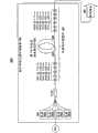
图2示出根据本发明的示例性系统100的图。系统100包括一段适于向通过其传播的光提供离子增益和拉曼增益的滤波器光纤102。在本示例中,滤波器光纤102是特别设计的掺Yb双包层滤波器光纤,其具有抑制在比选定的目标波长更长的波长下的不希望的斯托克斯级的W形折射率分布,并且在其工作带宽上具有正常色散。在2009年5月11日提交的61/177058号美国临时专利申请中描述了该光纤,该临时申请由与本申请相同的受让人拥有并且其全部内容通过引用包含在本文中。FIG. 2 shows a diagram of an
如下所述,根据本发明一方面的系统包括通过相应的斯托克斯频移在波长上分离的一系列嵌套的拉曼腔体。可以使用另选的结构和波长选择元件,例如使用熔合光纤耦合器或薄膜滤波器以构造WDM环路镜,来构造拉曼谐振器,这对本领域的技术人员来说是公知的。另外,还可以考虑线性的单向环或双向环腔体几何结构。此外,图2还示出该级联拉曼谐振器被配置作为激光器工作,但是还可以通过去除最后一组光栅并替代地注入该波长的信号而将其配置作为放大器工作。仅是为了说明的目的而将本讨论集中在使用布拉格光栅反射器件构造的谐振器。As described below, a system according to one aspect of the invention includes a series of nested Raman cavities separated in wavelength by corresponding Stokes shifts. Raman resonators can be constructed using alternative structures and wavelength selective elements, such as using fused fiber couplers or thin film filters to construct WDM loop mirrors, and are well known to those skilled in the art. In addition, linear one-way ring or two-way ring cavity geometries are also contemplated. Furthermore, Figure 2 also shows that the cascaded Raman resonator is configured to operate as a laser, but it can also be configured to operate as an amplifier by removing the last set of gratings and injecting a signal at that wavelength instead. For purposes of illustration only, this discussion focuses on resonators constructed using Bragg grating reflective devices.
出于本讨论的目的,术语“反射器件”被用于一般地指代高反射器件或输出耦合器或者类似的装置,并且术语“多个反射器件”被用于一般地指代多个高反射器件或输出耦合器或者类似的装置,或者它们的任意组合。For the purposes of this discussion, the term "reflective device" is used to refer generally to a highly reflective device or output coupler or similar device, and the term "reflective devices" is used to generally refer to a plurality of highly reflective devices or output couplers or similar devices, or any combination thereof.
在滤波器光纤102的输入端104提供第一多个高反射器件HR20-HR25,并且在滤波器光纤102的输出端106提供第二多个高反射器件HR26-HR30和输出耦合器OC20。在本示例中,使用光纤布拉格光栅或类似装置产生输入高反射器件HR20-HR25、输出高反射器件HR26-HR30和输出耦合器OC20,它们被写入与滤波器光纤102分离的光纤段中,并且然后被熔接到滤波器光纤102。应该指出,还可以将该光栅直接写入滤波器光纤102中。At the
系统100还包括泵浦功率源108,泵浦功率源108包括一个或多个二极管激光泵浦108a-d或者类似的装置。泵浦108a-d通过泵浦组合器,即锥形光纤束TFB20或其它适当装置,耦合到滤波器光纤102。
图2示出反射器件HR20-HR30和OC20的示例性波长。然而,要指出的是,这些波长和腔体数目特定于所描述的系统100,并且它们是出于本讨论的目的而提供的。应该理解,可以在具有其它波长的反射器件的系统中实现本发明。此外,还可以针对给定的应用修改反射器件的数量和配置。还应该理解,可以关于泵浦组合器TFB20修改输入光栅HR20-HR25的位置。在图2中,输入光栅HR20-HR25被示出在泵浦组合器TFB20的右侧,TFB20在嵌套激光器腔体的外部。然而,输入光栅HR20-HR25同样也可以位于泵浦组合器TFB20的左侧,泵浦组合器TFB20在嵌套激光器腔体的内部。Figure 2 shows exemplary wavelengths for reflective devices HR20-HR30 and OC20. Note, however, that these wavelengths and cavity numbers are specific to the
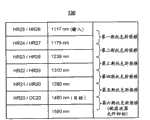
在图2中所示的示例性系统100中,反射器件HR10-HR20和OC20具有相应的波长和位置,使得它们形成一系列嵌套的波长匹配的反射器件对,第一反射器件位于滤波器光纤输入端104和第二反射器件位于滤波器光纤输入端106。该嵌套系列中的第一反射器件对包括高反射器件HR25和HR26,它们中的每一个具有1117nm的波长。该系列还有下列对:1175nm的HR24/HR27;1239nm的HR23/HR28;1310nm的HR22/HR29;1390nm的HR21/HR30;以及1480nm的HR20/OC20。这些对以及滤波器光纤102提供由相应的斯托克斯频移在波长上分开的一系列嵌套的拉曼腔体110。In the
图3是示出图2中所示的示例性系统100的反射器件波长的表格130。图3中的表格130还示出有五个斯托克斯频移发生。出于说明的目的,表格130中包括1590nm的第六斯托克斯频移。然而,如下面讨论的,该斯托克斯频移(以及其后的更高级斯托克斯频移)被滤波器光纤102抑制。FIG. 3 is a table 130 showing reflective device wavelengths for the
1117nm的第一反射器件对HR25/HR26和滤波器光纤102提供起到激光器腔体和拉曼腔体作用的组合腔体。由位于高反射器件HR25和HR26之间的滤波器光纤102中的Yb提供离子增益。当掺Yb增益介质在1117nm产生的功率超过受激拉曼散射的阈值时,产生第一斯托克斯频移的光,所述第一斯托克斯频移在本示例中大约为1175nm。The 1117nm first reflective device provides a combined cavity functioning as a laser cavity and a Raman cavity for the HR25/HR26 and the
该嵌套系列中的下一个反射器件对HR24/HR27具有对应于第一斯托克斯频移的波长。在1175nm下来自该光栅对的反馈将导致在该波长下的激光发射。根据本发明的另一方面,第一反射器件对位于下一个反射器件对内,以使第一腔体中的损耗最小化。其余的反射器件对HR23/HR28、HR22/HR29和HR21/HR30提供反馈,该系列中的每个光栅对的波长与该系列中的前一对的波长相差接近氧化硅光纤中相应的斯托克斯频移的量。当功率增加时,继续向更长波长进一步级联,直到在最后的光栅对HR20/OC20实现在目标波长(即1480nm)下的激光发射。因此,所述系列的斯托克斯频移提供从开始波长到目标波长的逐步转换。The next reflective device pair in the nested series, HR24/HR27, has a wavelength corresponding to the first Stokes shift. Feedback from this grating pair at 1175 nm will result in lasing at this wavelength. According to another aspect of the invention, a first pair of reflective devices is located within a next pair of reflective devices to minimize losses in the first cavity. The rest of the reflectors provide feedback to HR23/HR28, HR22/HR29 and HR21/HR30, the wavelength of each grating pair in the series differs from the wavelength of the previous pair in the series by close to the corresponding Stokes in silica fiber The amount of frequency shift. As the power is increased, the cascade continues further to longer wavelengths until lasing at the target wavelength (ie 1480nm) is achieved at the final grating pair HR20/OC20. Thus, the series of Stokes shifts provides a stepwise transition from the starting wavelength to the target wavelength.
在目标波长(即1480nm)下的光有可能经历进一步的拉曼增益。为了防止进一步级联到不希望的更长波长的斯托克斯级,该掺Yb增益介质具有基于W形凹陷包层设计的折射率分布,其中基本LP01模式在比目标波长更长的波长下截止。在2009年5月11日提交的61/177058号美国临时专利申请中描述了这种滤波器光纤的设计,该临时申请由本申请的受让人拥有,并且其全部内容通过引用包含在本文中。Light at the wavelength of interest (ie, 1480nm) has the potential to undergo further Raman gain. To prevent further cascading to the undesired longer-wavelength Stokes order, this Yb-doped gain medium has a refractive index profile based on a W-shaped depressed cladding design, where the fundamental LP01 mode is at a wavelength longer than the target wavelength cut off. The design of such a filter fiber is described in US Provisional Patent Application No. 61/177058, filed May 11, 2009, which is owned by the assignee of the present application and is incorporated herein by reference in its entirety.
具有基模截止的W形折射率分布的光纤已经被用在铒S波段放大器应用的情况中,并且还被用于抑制高功率的掺Yb光纤放大器中的拉曼散射。然而,这些光纤不适合于在高功率拉曼激光器的情况中使用,因为在这两种情况中滤波器光纤在宽波长范围上的色散特征都不是重要的考虑因素。如果在其中发生拉曼散射的光栅的色散是反常色散,那么调制不稳定性将导致超连续谱产生,而不是向离散的拉曼斯托克斯级散射。因此,针对级联拉曼散射设计的滤波器光纤必须在整个工作波长区域上具有正常色散。Fibers with a W-shaped index profile with a fundamental mode cutoff have been used in the case of Erbium S-band amplifier applications, and have also been used to suppress Raman scattering in high power Yb-doped fiber amplifiers. However, these fibers are not suitable for use in the context of high power Raman lasers, since in both cases the dispersion characteristics of the filter fibers over a broad wavelength range are not an important consideration. If the dispersion of the grating in which Raman scattering occurs is anomalous, then modulation instability will lead to supercontinuum generation rather than scattering to discrete Raman-Stokes orders. Therefore, filter fibers designed for cascaded Raman scattering must have normal dispersion over the entire operating wavelength region.
本讨论使用以ps/(nm-km)为单位的色散参数D。负值的D表示正常色散,而正值的D表示反常色散。在反常色散情况下,会发生在正常色散情况中不存在的调制不稳定和孤波形成等现象。标准的单模光纤在大约1300nm的波长下具有零色散,并且在比该零色散波长更长的波长下具有反常色散。This discussion uses the dispersion parameter D in units of ps/(nm-km). A negative value of D indicates normal dispersion, while a positive value of D indicates anomalous dispersion. In the case of anomalous dispersion, phenomena such as modulation instability and solitary wave formation, which do not exist in the case of normal dispersion, occur. Standard single-mode fiber has zero dispersion at a wavelength of about 1300 nm, and anomalous dispersion at wavelengths longer than this zero dispersion wavelength.
图4是示出针对从1000nm到1480nm的级联拉曼散射,同时抑制在更长的波长下的斯托克斯频移而设计的滤波器光纤的测得的损耗。图5是示出针对该滤波器光纤计算出的色散151和测得的色散152的曲线图150。在本文中描述的示例性系统中,提供基模截止的W形折射率分布与传统的双包层设计相结合以产生包层泵浦Yb光纤,该包层泵浦Yb光纤也将提供本文中所描述的级联拉曼散射。Figure 4 is a graph showing the measured loss of a filter fiber designed for cascaded Raman scattering from 1000 nm to 1480 nm while suppressing Stokes shift at longer wavelengths. FIG. 5 is a
在关于使用高功率Yb激光器来泵浦级联拉曼谐振器的系统的一些试验中,发现Yb激光高反射器件在该系统中是薄弱环节,这可能是由通过它传播的高功率造成的。已经观察到这种系统在例如使用这些系统泵浦掺铒光纤放大器等的各种情况下失效。因此,在有些情况下,使用MOPA配置可能是有益的,在MOPA配置中使用可以与功率放大器隔离的低功率振荡器。根据本发明的另一方面,功率放大和级联拉曼激光发射的功能在同一腔体内发生。In some experiments with systems using high power Yb lasers to pump cascaded Raman resonators, it was found that the Yb laser highly reflective device was the weak link in the system, probably due to the high power propagating through it. Such systems have been observed to fail in various situations such as pumping erbium doped fiber amplifiers etc. using these systems. Therefore, in some cases it may be beneficial to use a MOPA configuration in which a low power oscillator that can be isolated from the power amplifier is used. According to another aspect of the invention, the functions of power amplification and cascaded Raman lasing occur within the same cavity.
图6A和图6B是示出根据本发明另一方面的示例性的基于MOPA的系统200的图。系统200包括在两个不同功率范围的两级操作:低功率振荡器220(图6A)和高功率单腔体功率放大器及级联拉曼谐振器240(图6B)。振荡器220以及组合的放大器和级联拉曼谐振器240通过光学隔离器234(图6A)和波分复用器236(图6A)相互隔离。6A and 6B are diagrams illustrating an exemplary MOPA-based
振荡器220(图6A)包括一段激光激活双包层掺Yb光纤222或者能够提供适当的增益介质的其它光纤。高反射器件HR40和输出耦合器OC40分别位于光纤222的输入端224和输出端226。高反射器件HR40、输出耦合器OC40和光纤222提供激光器腔体228。泵浦230,如二极管激光器或其它适当的泵浦功率源,将泵浦功率输入到光纤222中。泵浦230通过锥形光纤束TFB40或类似装置耦合到光纤222。在本示例中,振荡器220在1117nm下提供大约15W的激光输出232。在该相对低的功率水平,高反射器件HR40具有最小的可靠性问题。The oscillator 220 (FIG. 6A) includes a length of laser-activated double-clad Yb-doped fiber 222 or other fiber capable of providing a suitable gain medium. The highly reflective element HR40 and the output coupler OC40 are located at the
振荡器输出232馈送通过光学隔离器234和波分复用器236,并且作为输入进入组合的功率放大器和级联拉曼谐振器240。The
组合的功率放大器和级联拉曼谐振器240(图6B)由一段掺Yb双包层滤波器光纤242(如上面关于图2的系统100讨论的滤波器光纤102)制成。如上面讨论的,滤波器光纤242适合于作为用于振荡器输出232的功率放大和用于拉曼激光发射的增益介质。在光纤输入244提供第一多个高反射器件HR41-HR45,并且在光纤输出246提供第二多个高反射器件HR46-HR50和输出耦合器OC41。输入反射器件HR41-HR45、输出反射器件HR46-HR50、输出耦合器OC41和光纤242在其间限定选定波长的一系列嵌套激光器腔体248。应该理解,输入反射器件HR41-HR45同样可以位于TFB41之前,使得TFB41在该嵌套谐振器内。A combined power amplifier and cascaded Raman resonator 240 (FIG. 6B) is made from a length of Yb-doped double-clad filter fiber 242 (as
泵浦源250将泵浦功率输入到滤波器光纤242内,用于振荡器输出230的功率放大。在图6B中,泵浦源250被示出为多个泵浦装置250a-d,如二极管激光器等。泵浦装置250通过锥形光纤束TFB41或其它适当装置耦合到滤波器光纤242。The
泵浦源250通过掺杂的滤波器光纤242中的离子增益将振荡器输出232放大到允许在滤波器光纤242中发生拉曼散射的功率水平。如上面讨论的,在该特定滤波器光纤242中,第一斯托克斯频移将传播光的波长增加到1175nm。高反射器件HR46被提供用于将1117nm的任何未被散射的光都反射回来。在所示出的配置200中,没有1117nm的输入高反射器件,以允许1117nm的辐射进入拉曼腔体。Pump
高反射器件HR41-HR50和输出耦合器OC41形成一系列嵌套的波长匹配对,该系列中的每对与前一对分开相应的斯托克斯频移。在该系列中的每对之间发生拉曼激光发射,结果实现从振荡器输出波长(即1117nm)到目标波长(即1489nm)的级联逐步转换。由高反射器件HR45和输出耦合器OC41提供与输出波长的耦合。滤波器光纤242提供比目标波长更长的波长的基模截止,从而防止不希望的更高级斯托克斯频移。Highly reflective devices HR41-HR50 and output coupler OC41 form a series of nested wavelength-matched pairs, each pair in the series separated from the previous pair by a corresponding Stokes frequency shift. Raman lasing occurs between each pair in the series, resulting in a cascaded stepwise conversion from the oscillator output wavelength (ie, 1117nm) to the target wavelength (ie, 1489nm). Coupling to the output wavelength is provided by highly reflective element HR45 and output coupler OC41. Filter fiber 242 provides fundamental mode cutoff at wavelengths longer than the target wavelength, thereby preventing unwanted higher order Stokes shifts.
隔离器234防止从放大器和谐振器240反向传播的光到达谐振器220,并干扰其操作。隔离器234保护振荡器220不受反向传播的隔离器带宽内所有波长的光的影响,所述波长包括与振荡器输出232的波长类似的波长。依赖于波长的损耗元件,即WDM 236,防止反向传播的斯托克斯辐射到达振荡器220。
在本发明的另一实践方式中,一种光产生和放大系统包括有效掺杂的拉曼滤波器光纤,其中在偏离峰值离子增益波长多于两个斯托克斯频移的波长下损耗增加。今天的有效掺杂滤波器光纤一般试图滤除偏离信号波长一个斯托克斯频移的拉曼增益。根据本发明的该实践方式,使用一种新的光纤,该光纤增加偏离信号多个斯托克斯频移的分布损耗,即相比于前面已经考虑的,增加信号和损耗之间极大的波长频移。因此,不仅使用该光纤的腔体几何结构是新颖的,而且该光纤本身也是新颖的。In another practice of the invention, a light generation and amplification system includes an efficiently doped Raman filter fiber, wherein the loss increases at wavelengths that deviate from the peak ion gain wavelength by more than two Stokes shifts . Today's efficiently doped filter fibers generally attempt to filter out Raman gain that is one Stokes shift away from the signal wavelength. According to this practice of the invention, a new type of fiber is used that increases the distributed loss by several Stokes shifts away from the signal, i.e. increases the extreme distance between signal and loss compared to what has been considered before. wavelength shift. Thus, not only are the cavity geometries using this fiber novel, but the fiber itself is also novel.
图7和图8A-B是示出根据本发明的上述各方面的总体技术的一对流程图300和350。应该理解,流程图300和350意图是说明性的,而不是限制性的。应该特别指出的是,所列出的方法的一些或全部要素可以在本发明的精神和范围内改变顺序、相互结合或者与未列出的要素结合、或者被分成多个子要素。另外,不必执行所有提到的要素。7 and 8A-B are a pair of
图7的流程图300中说明的技术包括以下要素:The technique illustrated in
框301:提供一段具有折射率分布并且在工作带宽上具有正常色散的激光激活滤波器光纤,该折射率分布抑制在比目标波长更长的波长下的不希望的斯托克斯级。Block 301: Providing a length of laser activated filter fiber having a refractive index profile that suppresses undesired Stokes orders at wavelengths longer than a target wavelength and having normal dispersion over an operating bandwidth.
框302:使用该激光激活光纤为在波长上分开大约相应斯托克斯频移的一系列嵌套拉曼腔体提供增益介质,Block 302: using the laser-activated fiber to provide a gain medium for a series of nested Raman cavities separated in wavelength by approximately the corresponding Stokes shift,
其中该系列嵌套腔体中的第一腔体是组合腔体,其被配置为提供从在选定的第一波长下的离子增益和反馈的组合产生的激光振荡,并且当所述第一波长下的光具有超过拉曼散射阈值的强度时向所述第一波长的第一斯托克斯频移下的光提供拉曼增益,wherein the first cavity in the series of nested cavities is a combination cavity configured to provide laser oscillation resulting from a combination of ion gain and feedback at a selected first wavelength, and when said first providing Raman gain to light at a first Stokes shift of said first wavelength when light at a wavelength has an intensity exceeding a Raman scattering threshold,
其中该系列嵌套拉曼腔体中的每个连续的拉曼腔体被配置为在每个连续的斯托克斯频移下提供拉曼增益,从而该系列嵌套拉曼腔体提供在所述第一波长和所述目标波长之间的逐步转换。Wherein each successive Raman cavity in the series of nested Raman cavities is configured to provide Raman gain at each successive Stokes frequency shift, so that the series of nested Raman cavities provides A stepwise transition between said first wavelength and said target wavelength.
步骤303:提供泵浦功率源,该泵浦功率源用于提供输入到所述滤波器光纤中的泵浦功率。Step 303: providing a pump power source, the pump power source is used to provide pump power input into the filter fiber.
图8A-B的流程图350中示出的技术包括以下要素:The technique shown in the flowchart 350 of FIGS. 8A-B includes the following elements:
框351:使用低功率振荡器以产生激光输出。Block 351 : Using a low power oscillator to generate laser output.
框352:将该振荡器耦合到组合的放大器和谐振器,其中所述振荡器的输出被提供作为进入所述组合的放大器和谐振器的输入,并且其中所述组合的放大器和谐振器提供在目标波长下的单模输出,Block 352: Coupling the oscillator to a combined amplifier and resonator, wherein the output of the oscillator is provided as an input into the combined amplifier and resonator, and wherein the combined amplifier and resonator is provided at single-mode output at the wavelength of interest,
其中所述组合的放大器和谐振器包括:wherein the combined amplifier and resonator comprises:
一段具有折射率分布并且在工作带宽上具有正常色散的激光激活和拉曼激活滤波器光纤,该折射率分布抑制在比目标波长更长的波长下的不希望的斯托克斯级,A length of laser-activated and Raman-activated filter fiber having a refractive index profile that suppresses undesired Stokes orders at wavelengths longer than the wavelength of interest, with normal dispersion over the operating bandwidth,
耦合到所述滤波器光纤的泵浦功率源,其用于提供输入到所述滤波器光纤中的泵浦功率,从而所述振荡器输出被放大到超过所述滤波器光纤的拉曼散射阈值的水平,a pump power source coupled to the filter fiber for providing pump power input into the filter fiber such that the oscillator output is amplified beyond the Raman scattering threshold of the filter fiber s level,
位于所述滤波器光纤的输出端的所述振荡波长的第一高反射器件,其用于将未被散射的所述振荡波长下的光反射回来,a first highly reflective device at the oscillation wavelength located at the output end of the filter fiber, which is used to reflect back unscattered light at the oscillation wavelength,
一系列反射器件对,每对包括提供在所述滤波器光纤的输入端的相应波长的相应第一反射器件和提供在所述滤波器光纤的输出端的相应波长的相应第二反射器件,其中该系列中的每个反射器件对和所述滤波器光纤被配置为提供一系列嵌套拉曼腔体,该系列嵌套拉曼腔体提供所述振荡波长和所述目标波长之间的逐步转换,以及a series of reflective device pairs, each pair comprising a respective first reflective device providing a respective wavelength at an input end of said filter fiber and a respective second reflective device providing a respective wavelength at an output end of said filter fiber, wherein the series Each reflective device pair and said filter fiber in are configured to provide a series of nested Raman cavities providing a stepwise conversion between said oscillation wavelength and said target wavelength, as well as
最后反射器件对,其包括提供在所述滤波器光纤输入端的高反射器件和写入所述滤波器光纤输出端的输出耦合器,用以提供耦合出所述滤波器光纤的所述目标波长的输出。A final reflective device pair comprising a highly reflective device provided at an input end of said filter fiber and an output coupler written to an output end of said filter fiber to provide an output coupled out of said filter fiber at said target wavelength .
框353:在所述振荡器和放大器之间连接反向传播预防装置,从而所述振荡器与所述放大器和谐振器光学隔离,并且所述振荡器可在第一功率水平范围内工作,所述放大器和振荡器可在超过所述第一功率水平范围的第二功率水平范围内工作。Block 353: connecting a backpropagation prevention device between the oscillator and an amplifier, such that the oscillator is optically isolated from the amplifier and resonator, and the oscillator is operable within a first range of power levels, the The amplifier and oscillator are operable within a second power level range that exceeds the first power level range.
框354:使用所述滤波器光纤和所述泵浦功率源放大所述振荡器输出并且产生在所述目标波长下的激光输出。Block 354: Amplifying the oscillator output and producing a laser output at the target wavelength using the filter fiber and the pump power source.
注意,所述拉曼增益带宽是相当大的,并且所述反射器件可以位于所述增益带宽内的任何位置,而不必在所述增益的峰值处。Note that the Raman gain bandwidth is quite large, and the reflective device can be located anywhere within the gain bandwidth, not necessarily at the peak of the gain.
上述系统和技术可适用于许多其它情况,包括但不限于:线性和环拉曼谐振器;拉曼放大器结构;包括第二泵浦的双泵浦系统,第二泵浦不与任何一个拉曼腔体谐振,但是仍在所述拉曼增益带宽内;撞击倍频晶体,窄线宽的偏振输出对该倍频晶体是有益的;例如在参数系统中使用的脉动或调制的操作等等。The systems and techniques described above are applicable to many other situations, including but not limited to: linear and ring Raman resonators; Raman amplifier structures; dual pump systems including a second pump that is not coupled to either Raman The cavity is resonant, but still within the Raman gain bandwidth; strikes a frequency doubling crystal for which a narrow linewidth polarized output is beneficial; operations such as dithering or modulation used in parametric systems, etc.
对于拉曼放大器要指出的是,它们的结构除了放大器拉曼腔体被构造为没有最后的斯托克斯频移和输出耦合器以外,典型地类似于拉曼激光器的结构。此外,还在最后的斯托克斯频移下将种子激光耦合到拉曼腔体中。可以将来自种子源的种子输入在不同的位置注入到放大器中。该种子激光控制多个放大器性质,例如偏振输出、窄线宽、可调谐性等等。It is noted for Raman amplifiers that their structure is typically similar to that of a Raman laser, except that the amplifier Raman cavity is constructed without the final Stokes shift and the output coupler. In addition, a seed laser is also coupled into the Raman cavity at the final Stokes shift. The seed input from the seed source can be injected into the amplifier at different locations. This seed laser controls multiple amplifier properties such as polarization output, narrow linewidth, tunability, and more.
尽管以上描述包括使本领域技术人员能够实现本发明的细节,但是应该理解,本描述本质上是说明性的,并且对于受益于这些教导的本领域技术人员来说,对以上描述的许多修改及改变是显而易见的。因此,希望本发明仅由所附权利要求限定,并且如现有技术所允许的那样宽泛地解释权利要求。While the above description includes details to enable one skilled in the art to practice the invention, it should be understood that this description is illustrative in nature and that many modifications and adaptations of the above description will come to those skilled in the art having the benefit of these teachings. The changes are palpable. Accordingly, it is intended that the present invention be limited only by the appended claims and to interpret the claims as broadly as the prior art will allow.
Claims (22)
Applications Claiming Priority (3)
| Application Number | Priority Date | Filing Date | Title |
|---|---|---|---|
| US17705809P | 2009-05-11 | 2009-05-11 | |
| US61/177,058 | 2009-05-11 | ||
| PCT/US2010/034423WO2010132482A1 (en) | 2009-05-11 | 2010-05-11 | Cascaded raman fiber laser system based on filter fiber |
Publications (2)
| Publication Number | Publication Date |
|---|---|
| CN102388512Atrue CN102388512A (en) | 2012-03-21 |
| CN102388512B CN102388512B (en) | 2013-12-04 |
Family
ID=43062199
Family Applications (4)
| Application Number | Title | Priority Date | Filing Date |
|---|---|---|---|
| CN2010800101534APendingCN102449936A (en) | 2009-05-11 | 2010-05-11 | Systems and techniques for suppressing backward lasing in high-power cascaded raman fiber lasers |
| CN2010800101553AActiveCN102388512B (en) | 2009-05-11 | 2010-05-11 | Cascaded Raman fiber laser system based on filter fiber |
| CN201080010143.0AActiveCN102449864B (en) | 2009-05-11 | 2010-05-11 | Systems and methods for cascaded raman lasting at high power levels |
| CN201080010152.XAActiveCN102439805B (en) | 2009-05-11 | 2010-05-11 | The filter fiber and manufacturing technology thereof that use in application is launched at raman laser |
Family Applications Before (1)
| Application Number | Title | Priority Date | Filing Date |
|---|---|---|---|
| CN2010800101534APendingCN102449936A (en) | 2009-05-11 | 2010-05-11 | Systems and techniques for suppressing backward lasing in high-power cascaded raman fiber lasers |
Family Applications After (2)
| Application Number | Title | Priority Date | Filing Date |
|---|---|---|---|
| CN201080010143.0AActiveCN102449864B (en) | 2009-05-11 | 2010-05-11 | Systems and methods for cascaded raman lasting at high power levels |
| CN201080010152.XAActiveCN102439805B (en) | 2009-05-11 | 2010-05-11 | The filter fiber and manufacturing technology thereof that use in application is launched at raman laser |
Country Status (6)
| Country | Link |
|---|---|
| US (4) | US20100284061A1 (en) |
| EP (4) | EP2430716B1 (en) |
| JP (6) | JP5611328B2 (en) |
| KR (4) | KR101747153B1 (en) |
| CN (4) | CN102449936A (en) |
| WO (4) | WO2010132466A1 (en) |
Cited By (7)
| Publication number | Priority date | Publication date | Assignee | Title |
|---|---|---|---|---|
| CN103022865A (en)* | 2012-12-14 | 2013-04-03 | 清华大学 | Multi-wavelength pumping composite fiber optic laser |
| CN105431754A (en)* | 2013-03-15 | 2016-03-23 | 恩耐激光技术有限公司 | Rotated non-circular and non-elliptical core fiber and devices using same |
| CN105470802A (en)* | 2015-12-30 | 2016-04-06 | 昂纳信息技术(深圳)有限公司 | All-fiber acousto-optic Q laser and output method thereof |
| CN110235320A (en)* | 2017-01-31 | 2019-09-13 | 株式会社藤仓 | Fiber laser system and its control method |
| CN111817120A (en)* | 2020-07-20 | 2020-10-23 | 长沙大科激光科技有限公司 | Optical fiber for inhibiting stimulated Raman scattering effect and application thereof |
| CN111903018A (en)* | 2018-03-30 | 2020-11-06 | 株式会社藤仓 | Fiber laser device, method for manufacturing fiber laser device, and method for setting fiber laser device |
| CN113067252A (en)* | 2015-07-15 | 2021-07-02 | 努布鲁有限公司 | Applications, methods and systems for laser-transmissive addressable arrays |
Families Citing this family (51)
| Publication number | Priority date | Publication date | Assignee | Title |
|---|---|---|---|---|
| KR101747153B1 (en)* | 2009-05-11 | 2017-06-14 | 오에프에스 피텔 엘엘씨 | Filter fiber for use in raman lasing applications and techniques for manufacturing same |
| JP5353582B2 (en)* | 2009-09-10 | 2013-11-27 | 富士通株式会社 | Optical amplifier |
| US8441718B2 (en)* | 2009-11-23 | 2013-05-14 | Lockheed Martin Corporation | Spectrally beam combined laser system and method at eye-safer wavelengths |
| ES3001658T3 (en)* | 2010-02-01 | 2025-03-05 | Draka Comteq Bv | Non-zero dispersion shifted optical fiber having a short cutoff wavelength |
| DE112011101288T5 (en) | 2010-04-12 | 2013-02-07 | Lockheed Martin Corporation | Beam diagnostic and feedback system and methods for spectrally beam combined lasers |
| US7929818B1 (en)* | 2010-06-30 | 2011-04-19 | Corning Incorporated | Large effective area fiber with graded index GE-free core |
| US8472486B1 (en)* | 2011-08-17 | 2013-06-25 | The United States Of America As Represented By The Secretary Of The Air Force | Seeded raman amplifier for applications in the 1100-1500 nm spectral region |
| JP2014532894A (en)* | 2011-10-19 | 2014-12-08 | オーエフエス ファイテル,エルエルシー | Cascade Raman lasing system |
| US9602200B2 (en) | 2012-02-07 | 2017-03-21 | Afl Telecommunications Llc | Multiple wavelength optical assemblies for inline measurement of optical power and fiber optic networks |
| GB2505409B (en)* | 2012-08-27 | 2016-08-03 | V-Gen Ltd | Generation of narrow line width high power optical pulses |
| US9366810B2 (en)* | 2012-08-29 | 2016-06-14 | Ofs Fitel, Llc | Double-clad, gain-producing fibers with increased cladding absoroption while maintaining single-mode operation |
| US9366806B2 (en)* | 2012-08-29 | 2016-06-14 | Ofs Fitel, Llc | Gain-producing fibers with increased cladding absorption while maintaining single-mode operation |
| IL221918A (en) | 2012-09-12 | 2016-11-30 | V-Gen Ltd | Optical isolator |
| US20140198377A1 (en)* | 2013-01-15 | 2014-07-17 | Omron Corporation | Laser oscillator |
| KR101440580B1 (en)* | 2013-01-23 | 2014-09-17 | 주식회사 에이제이월드 | Optical connector having filtering function |
| US9164230B2 (en)* | 2013-03-15 | 2015-10-20 | Ofs Fitel, Llc | High-power double-cladding-pumped (DC) erbium-doped fiber amplifier (EDFA) |
| US10971896B2 (en) | 2013-04-29 | 2021-04-06 | Nuburu, Inc. | Applications, methods and systems for a laser deliver addressable array |
| US10562132B2 (en) | 2013-04-29 | 2020-02-18 | Nuburu, Inc. | Applications, methods and systems for materials processing with visible raman laser |
| US11612957B2 (en)* | 2016-04-29 | 2023-03-28 | Nuburu, Inc. | Methods and systems for welding copper and other metals using blue lasers |
| WO2014177724A1 (en)* | 2013-05-03 | 2014-11-06 | Norwegian University Of Science And Technology (Ntnu) | Optical fiber amplifier |
| US9835778B1 (en) | 2013-09-13 | 2017-12-05 | Lockheed Martin Corporation | Apparatus and method for a diamond substrate for a multi-layered dielectric diffraction grating |
| JP5680170B1 (en)* | 2013-11-14 | 2015-03-04 | 株式会社フジクラ | Fiber laser equipment |
| CN105006733A (en)* | 2014-04-22 | 2015-10-28 | 深圳激扬光电有限公司 | High-peak power laser, and protection method and apparatus thereof |
| US9397466B2 (en) | 2014-07-11 | 2016-07-19 | Nlight, Inc. | High power chirally coupled core optical amplification systems and methods |
| CN107078801B (en) | 2014-08-06 | 2020-02-14 | 莫克斯网络有限责任公司 | Distributed Raman amplifier system |
| US9793679B2 (en) | 2014-08-06 | 2017-10-17 | Mox Networks, LLC | Distributed Raman amplifier systems |
| US11646549B2 (en) | 2014-08-27 | 2023-05-09 | Nuburu, Inc. | Multi kW class blue laser system |
| TWI556532B (en)* | 2014-09-16 | 2016-11-01 | Ipg光電公司 | Broadband red light generator for red, green and blue displays |
| JP6140743B2 (en)* | 2015-02-12 | 2017-05-31 | 株式会社フジクラ | Fiber laser device and method for manufacturing amplification coil |
| US20160285230A1 (en)* | 2015-03-26 | 2016-09-29 | Ofs Fitel, Llc | Systems and techniques for termination of ports in fiber lasers |
| US12172377B2 (en) | 2016-04-29 | 2024-12-24 | Nuburu, Inc. | Blue laser metal additive manufacturing system |
| US20220072659A1 (en)* | 2016-04-29 | 2022-03-10 | Nuburu, Inc. | Methods and Systems for Reducing Hazardous Byproduct from Welding Metals Using Lasers |
| WO2017189982A1 (en) | 2016-04-29 | 2017-11-02 | Nuburu, Inc. | Visible laser additive manufacturing |
| JP7316791B2 (en)* | 2016-04-29 | 2023-07-28 | ヌブル インク | Monolithic visible wavelength fiber laser |
| KR102350424B1 (en)* | 2016-07-01 | 2022-01-11 | 아이피지 포토닉스 코포레이션 | Fiber Laser System With Mechanism for Inducing Parasitic Light Loss |
| CA2971601C (en) | 2017-01-27 | 2022-06-21 | Teraxion Inc. | Optical fiber filter of wideband deleterious light and uses thereof |
| JP6911153B2 (en) | 2017-01-31 | 2021-07-28 | ヌブル インク | Methods and systems for welding copper using a blue laser |
| US11473982B2 (en)* | 2017-03-02 | 2022-10-18 | Ofs Fitel, Llc | Broad bandwidth graded index multimode optical fiber for distributed temperature sensing in the 1550 NM region |
| EP4220252A3 (en) | 2017-04-21 | 2023-08-09 | Nuburu, Inc. | Multi-clad optical fiber |
| WO2019013862A2 (en)* | 2017-05-15 | 2019-01-17 | Ipg Photonics Corporation | High power cladding pumped single mode fiber raman laser |
| KR102416499B1 (en) | 2017-06-13 | 2022-07-01 | 누부루 인크. | Ultra-Dense Wavelength Beam Combination Laser System |
| CN108695680B (en)* | 2018-06-22 | 2020-10-02 | 电子科技大学 | Multimode fiber cascade Raman random laser of all-fiber LD pumping |
| CN109193336B (en)* | 2018-10-29 | 2019-11-05 | 中国人民解放军国防科技大学 | Method for suppressing stimulated Brillouin scattering by fiber laser oscillator |
| CN109193337A (en)* | 2018-10-29 | 2019-01-11 | 中国人民解放军国防科技大学 | Stimulated Raman Scattering Suppression Method for High Power Fiber Laser Amplifier System |
| WO2020107030A1 (en)* | 2018-11-23 | 2020-05-28 | Nuburu, Inc | Multi-wavelength visible laser source |
| WO2020139704A1 (en)* | 2018-12-28 | 2020-07-02 | Nlight, Inc. | Optical fiber devices and methods for suppressing stimulated raman scattering (srs) |
| CA3127651A1 (en) | 2019-02-02 | 2020-08-06 | Nuburu, Inc. | High reliability, high power, high brightness blue laser diode systems and methods of making the same |
| EP3997766A4 (en)* | 2019-07-10 | 2023-08-16 | Ofs Fitel Llc | WIDELY TUNABLE ULTRA FAST FIBER LASER SOURCE |
| CN112397978B (en)* | 2019-08-15 | 2022-01-28 | 中国科学院大连化学物理研究所 | Optical fiber Raman laser of alkali metal laser pump |
| EP4321910A4 (en)* | 2021-04-08 | 2025-03-26 | Furukawa Electric Co., Ltd. | OPTICAL FIBER |
| EP4352836A4 (en)* | 2021-06-10 | 2025-04-30 | Ofs Fitel Llc | SYSTEMS AND METHODS FOR WAVELENGTH DIVISION MUNICIPALITY |
Citations (3)
| Publication number | Priority date | Publication date | Assignee | Title |
|---|---|---|---|---|
| US20030021302A1 (en)* | 2001-07-18 | 2003-01-30 | Grudinin Anatoly Borisovich | Raman cascade light sources |
| EP1518305B1 (en)* | 2002-06-28 | 2006-03-15 | Photonami Inc. | A back reflection insensitive electro-optical interface and a method of coupling the same to a waveguide |
| US20070297462A1 (en)* | 2004-10-06 | 2007-12-27 | The Regents Of The University Of California | Cascaded cavity silicon raman laser with electrical modulation, switching, and active mode locking capability |
Family Cites Families (75)
| Publication number | Priority date | Publication date | Assignee | Title |
|---|---|---|---|---|
| US4947134A (en)* | 1987-10-30 | 1990-08-07 | American Telephone And Telegraph Company | Lightwave systems using optical amplifiers |
| US4894833A (en)* | 1988-08-09 | 1990-01-16 | General Electric Company | Surface emitting lasers with combined output |
| JPH0561079A (en)* | 1991-08-29 | 1993-03-12 | Sumitomo Electric Ind Ltd | Optical filter |
| JPH05224102A (en)* | 1992-02-07 | 1993-09-03 | Ando Electric Co Ltd | Optical module for excitation with a little return light |
| US5892615A (en)* | 1997-03-17 | 1999-04-06 | Sdl, Inc. | Output power enhancement in optical fiber lasers |
| JP2007516600A (en)* | 1997-03-21 | 2007-06-21 | イムラ アメリカ インコーポレイテッド | High energy fiber optic amplifier for picosecond-nanosecond pulses for advanced material processing applications |
| US5815518A (en)* | 1997-06-06 | 1998-09-29 | Lucent Technologies Inc. | Article comprising a cascaded raman fiber laser |
| US5864644A (en)* | 1997-07-21 | 1999-01-26 | Lucent Technologies Inc. | Tapered fiber bundles for coupling light into and out of cladding-pumped fiber devices |
| US5887093A (en)* | 1997-09-12 | 1999-03-23 | Lucent Technologies Incorporated | Optical fiber dispersion compensation |
| US6141470A (en)* | 1998-02-06 | 2000-10-31 | Lucent Technologies, Inc. | Magnetically reconfigurable optical grating devices and communication systems |
| WO1999043117A2 (en)* | 1998-02-20 | 1999-08-26 | Sdl, Inc. | Upgradable, gain flattened fiber amplifiers for wdm applications |
| US6310899B1 (en)* | 1998-04-15 | 2001-10-30 | Lucent Technologies Inc. | Cascaded raman resonator system and apparatus |
| US6005877A (en)* | 1998-04-22 | 1999-12-21 | Hughes Electronics Corporation | Distributed-feedback fiber-laser with asymmetric output ports |
| JP5069825B2 (en)* | 1998-06-16 | 2012-11-07 | エクステラ コミュニケイションズ インコーポレイテッド | Optical fiber compensation for dispersion, gain tilt, and band-pumping nonlinearity |
| WO2000005622A1 (en)* | 1998-07-23 | 2000-02-03 | The Furukawa Electric Co., Ltd. | Raman amplifier, optical repeater, and raman amplification method |
| US6556346B1 (en)* | 1998-09-22 | 2003-04-29 | Corning O.T.I.Spa | Optical amplifying unit and optical transmission system |
| US6525872B1 (en)* | 1999-02-11 | 2003-02-25 | Jds Uniphase Corporation | Fiber grating-stabilized, semiconductor pump source |
| US6407855B1 (en)* | 1999-10-29 | 2002-06-18 | Sdl, Inc. | Multiple wavelength optical sources |
| WO2001065646A2 (en)* | 2000-02-29 | 2001-09-07 | Jds Uniphase Corporation | Multiple stage optical fiber amplifier |
| JP2001249369A (en)* | 2000-03-02 | 2001-09-14 | Nec Corp | Optical amplifier and optical amplification repeater using the same, and wavelength multiplex transmission device |
| US6885683B1 (en)* | 2000-05-23 | 2005-04-26 | Imra America, Inc. | Modular, high energy, widely-tunable ultrafast fiber source |
| US6621835B1 (en)* | 2000-06-12 | 2003-09-16 | Jds Uniphase Corporation | Raman amplifier in ring configuration |
| JP2002006348A (en)* | 2000-06-21 | 2002-01-09 | Mitsubishi Electric Corp | Optical amplifier |
| US6700696B2 (en)* | 2000-08-09 | 2004-03-02 | Jds Uniphase Corporation | High order fiber Raman amplifiers |
| US6941054B2 (en) | 2000-08-31 | 2005-09-06 | Pirelli S.P.A. | Optical transmission link with low slope, raman amplified fiber |
| US6594288B1 (en)* | 2000-11-06 | 2003-07-15 | Cidra Corporation | Tunable raman laser and amplifier |
| KR100358158B1 (en)* | 2000-11-21 | 2002-10-25 | 주식회사 케이티 | Hybrid fiber amplifier using a dispersion compensating Raman amplifier with a pump depolarizer |
| US6563995B2 (en)* | 2001-04-02 | 2003-05-13 | Lightwave Electronics | Optical wavelength filtering apparatus with depressed-index claddings |
| WO2002093704A1 (en)* | 2001-05-15 | 2002-11-21 | Ocg Technology Licensing, Llc | Optical fiber and system containing same |
| WO2002095885A1 (en)* | 2001-05-22 | 2002-11-28 | Mitsubishi Denki Kabushiki Kaisha | Fiber laser |
| US6845194B2 (en)* | 2001-06-27 | 2005-01-18 | Furukawa Electric North America Inc. | Optical bandpass filter using long period gratings |
| US7039076B2 (en)* | 2001-08-10 | 2006-05-02 | Jds Uniphase Corporation | Fiber amplifier system for producing visible light |
| JP3917392B2 (en)* | 2001-08-28 | 2007-05-23 | 日本電信電話株式会社 | Design method of Raman amplifier |
| DE60220369T2 (en)* | 2002-01-11 | 2007-09-20 | Alcatel Lucent | Cascade Raman fiber laser and optical system with such a laser |
| JP4007812B2 (en)* | 2002-01-18 | 2007-11-14 | 富士通株式会社 | Raman amplifier, wavelength division multiplexing optical communication system, and control method of Raman amplification |
| US6757468B2 (en)* | 2002-03-14 | 2004-06-29 | Corning Incorporated | Dispersion compensation optical fiber and optical transmission line using same |
| US6721088B2 (en)* | 2002-03-15 | 2004-04-13 | Ofs Fitel | Single-source multiple-order raman amplifier for optical transmission systems |
| US20050259315A1 (en)* | 2002-05-31 | 2005-11-24 | Alexis Debut | Cascaded raman pump for raman amplification in optical systems |
| US7149231B2 (en)* | 2002-10-04 | 2006-12-12 | Spectra Systems Corporation | Monolithic, side-pumped, passively Q-switched solid-state laser |
| DE60316989T2 (en)* | 2002-12-10 | 2008-07-24 | Nikon Corp. | ULTRAVIOLETT LIGHT SOURCE, PHOTOTHERAPY DEVICE USING AN ULTRAVIOLET LIGHT SOURCE AND EXPOSURE SYSTEM USING AN ULTRAVIOLET LIGHT SOURCE |
| US6952517B2 (en) | 2003-01-29 | 2005-10-04 | Furukawa Electric North America | Method for the manufacture of optical fibers, improved optical fibers, and improved raman fiber amplifier communication systems |
| ATE348425T1 (en)* | 2003-03-03 | 2007-01-15 | Cit Alcatel | RAMAN FIBER LASER WITH MULTI-WAVE LENGTH, STABLE, SMALL OUTPUT FOR SEED LASER APPLICATIONS |
| FR2852154B1 (en)* | 2003-03-04 | 2005-05-20 | Cit Alcatel | AMPLIFIER OPTICAL FIBER WITH DOPE RING AND AMPLIFIER CONTAINING SUCH A FIBER |
| FR2854249B1 (en)* | 2003-04-25 | 2005-07-08 | Cit Alcatel | DEVICE AND METHOD FOR SIGNAL PROPAGATION MODE TRANSFORMATION BY INTERFERENCE |
| DE60310382T2 (en)* | 2003-05-28 | 2007-04-12 | Alcatel | Method for adjusting the spectrum of a multi-wavelength Raman laser |
| US7046433B2 (en)* | 2003-12-30 | 2006-05-16 | The Furukawa Electric Co., Ltd. | Optical fiber, and optical module and Raman amplifier using the optical fiber |
| CN1806200A (en)* | 2004-05-20 | 2006-07-19 | 古河电气工业株式会社 | Optical fiber for raman amplification, optical fiber coil, raman amplifier, and optical communication system |
| US7590155B2 (en)* | 2004-08-05 | 2009-09-15 | Jian Liu | Hybrid high power laser to achieve high repetition rate and high pulse energy |
| JP2006108426A (en)* | 2004-10-06 | 2006-04-20 | Kansai Electric Power Co Inc:The | Optical fiber raman laser |
| US7171074B2 (en)* | 2004-11-16 | 2007-01-30 | Furakawa Electric North America Inc. | Large mode area fibers using higher order modes |
| US7508853B2 (en)* | 2004-12-07 | 2009-03-24 | Imra, America, Inc. | Yb: and Nd: mode-locked oscillators and fiber systems incorporated in solid-state short pulse laser systems |
| US7130512B2 (en)* | 2005-03-04 | 2006-10-31 | Corning Incorporated | Supercontinuum emitting device |
| US7420994B2 (en)* | 2005-03-04 | 2008-09-02 | Corning Incorporated | Pulsed cascaded Raman laser |
| US7236672B2 (en)* | 2005-03-30 | 2007-06-26 | Corning Incorporated | Optical systems utilizing optical fibers transmitting high power signal and a method of operating such systems |
| JP2006286844A (en)* | 2005-03-31 | 2006-10-19 | Furukawa Electric Co Ltd:The | Optical fiber amplifier |
| US7409128B2 (en)* | 2005-06-29 | 2008-08-05 | Lucent Technologies Inc. | Pumping arrangement for fiber amplifiers with reduced reflective feedback |
| US20070003198A1 (en)* | 2005-06-29 | 2007-01-04 | Lance Gibson | Low loss optical fiber designs and methods for their manufacture |
| US7620077B2 (en)* | 2005-07-08 | 2009-11-17 | Lockheed Martin Corporation | Apparatus and method for pumping and operating optical parametric oscillators using DFB fiber lasers |
| US7391561B2 (en)* | 2005-07-29 | 2008-06-24 | Aculight Corporation | Fiber- or rod-based optical source featuring a large-core, rare-earth-doped photonic-crystal device for generation of high-power pulsed radiation and method |
| JP4699131B2 (en)* | 2005-08-05 | 2011-06-08 | 株式会社フジクラ | Optical fiber laser, optical fiber amplifier, MOPA optical fiber laser |
| US7505489B2 (en)* | 2005-10-17 | 2009-03-17 | Polaronyx, Inc. | Ultrahigh energy short pulse lasers |
| JP5269764B2 (en)* | 2006-04-28 | 2013-08-21 | コーニング インコーポレイテッド | Pulsed UV and visible Raman laser system |
| US20080089366A1 (en)* | 2006-05-15 | 2008-04-17 | Polaronyx, Inc. | High energy short pulse fiber laser achieved by combining pulse shaping, polarization shaping and spectral shaping |
| JP5064777B2 (en)* | 2006-12-08 | 2012-10-31 | 古河電気工業株式会社 | Laser equipment |
| US7916386B2 (en)* | 2007-01-26 | 2011-03-29 | Ofs Fitel, Llc | High power optical apparatus employing large-mode-area, multimode, gain-producing optical fibers |
| AU2008213831B2 (en)* | 2007-02-05 | 2012-12-20 | Ofs Fitel, Llc | Selectively pumping a gain-doped region of an optical fiber |
| US8081376B2 (en)* | 2007-06-06 | 2011-12-20 | Sumitomo Electric Industries, Ltd. | Multi-stage fiber amplifier to suppress Raman scattered light |
| CN101584093B (en)* | 2007-06-27 | 2011-11-23 | 株式会社藤仓 | Fiber laser with excellent resistance to reflected light |
| WO2009014623A1 (en)* | 2007-07-20 | 2009-01-29 | Corning Incorporated | Large-mode-area optical fiber |
| JP4873645B2 (en)* | 2007-08-15 | 2012-02-08 | 新日本製鐵株式会社 | Optical fiber Raman laser device |
| CN100492148C (en)* | 2007-12-13 | 2009-05-27 | 中国科学院上海光学精密机械研究所 | All-fiber narrow-linewidth hundreds of nanosecond pulse signal system |
| CN101217227A (en)* | 2008-01-16 | 2008-07-09 | 中国科学院上海光学精密机械研究所 | Protective Isolation Device for Pump Source Laser Diode |
| JP4834718B2 (en)* | 2008-01-29 | 2011-12-14 | キヤノン株式会社 | Pulse laser device, terahertz generator, terahertz measuring device, and terahertz tomography device |
| JP5323562B2 (en)* | 2008-03-31 | 2013-10-23 | 古河電気工業株式会社 | Cascade Raman laser |
| KR101747153B1 (en)* | 2009-05-11 | 2017-06-14 | 오에프에스 피텔 엘엘씨 | Filter fiber for use in raman lasing applications and techniques for manufacturing same |
- 2010
- 2010-05-11KRKR1020117026881Apatent/KR101747153B1/enactiveActive
- 2010-05-11JPJP2012510918Apatent/JP5611328B2/enactiveActive
- 2010-05-11WOPCT/US2010/034406patent/WO2010132466A1/enactiveApplication Filing
- 2010-05-11USUS12/778,025patent/US20100284061A1/ennot_activeAbandoned
- 2010-05-11KRKR1020117026887Apatent/KR20120023651A/ennot_activeWithdrawn
- 2010-05-11WOPCT/US2010/034321patent/WO2010132405A1/enactiveApplication Filing
- 2010-05-11CNCN2010800101534Apatent/CN102449936A/enactivePending
- 2010-05-11EPEP10775422.8Apatent/EP2430716B1/enactiveActive
- 2010-05-11USUS12/777,963patent/US8792157B2/enactiveActive
- 2010-05-11EPEP10775413.7Apatent/EP2430715B1/enactiveActive
- 2010-05-11WOPCT/US2010/034423patent/WO2010132482A1/enactiveApplication Filing
- 2010-05-11KRKR1020117026882Apatent/KR101723802B1/enactiveActive
- 2010-05-11JPJP2012510945Apatent/JP5773991B2/enactiveActive
- 2010-05-11JPJP2012510949Apatent/JP2012527018A/enactivePending
- 2010-05-11CNCN2010800101553Apatent/CN102388512B/enactiveActive
- 2010-05-11CNCN201080010143.0Apatent/CN102449864B/enactiveActive
- 2010-05-11USUS12/777,465patent/US8428409B2/enactiveActive
- 2010-05-11EPEP10775368.3Apatent/EP2430714A4/ennot_activeWithdrawn
- 2010-05-11JPJP2012510955Apatent/JP2012527019A/enactivePending
- 2010-05-11EPEP10775429.3Apatent/EP2430781A4/ennot_activeWithdrawn
- 2010-05-11WOPCT/US2010/034435patent/WO2010132493A1/enactiveApplication Filing
- 2010-05-11USUS12/778,012patent/US8351111B2/ennot_activeExpired - Fee Related
- 2010-05-11KRKR1020117026884Apatent/KR101764156B1/enactiveActive
- 2010-05-11CNCN201080010152.XApatent/CN102439805B/enactiveActive
- 2014
- 2014-12-19JPJP2014256947Apatent/JP2015084113A/enactivePending
- 2017
- 2017-04-13JPJP2017079491Apatent/JP2017126088A/enactivePending
Patent Citations (3)
| Publication number | Priority date | Publication date | Assignee | Title |
|---|---|---|---|---|
| US20030021302A1 (en)* | 2001-07-18 | 2003-01-30 | Grudinin Anatoly Borisovich | Raman cascade light sources |
| EP1518305B1 (en)* | 2002-06-28 | 2006-03-15 | Photonami Inc. | A back reflection insensitive electro-optical interface and a method of coupling the same to a waveguide |
| US20070297462A1 (en)* | 2004-10-06 | 2007-12-27 | The Regents Of The University Of California | Cascaded cavity silicon raman laser with electrical modulation, switching, and active mode locking capability |
Cited By (12)
| Publication number | Priority date | Publication date | Assignee | Title |
|---|---|---|---|---|
| CN103022865A (en)* | 2012-12-14 | 2013-04-03 | 清华大学 | Multi-wavelength pumping composite fiber optic laser |
| CN105431754A (en)* | 2013-03-15 | 2016-03-23 | 恩耐激光技术有限公司 | Rotated non-circular and non-elliptical core fiber and devices using same |
| CN105431754B (en)* | 2013-03-15 | 2018-05-15 | 恩耐公司 | Rotated non-circular and non-elliptical core fiber and devices using same |
| CN113067252A (en)* | 2015-07-15 | 2021-07-02 | 努布鲁有限公司 | Applications, methods and systems for laser-transmissive addressable arrays |
| CN105470802A (en)* | 2015-12-30 | 2016-04-06 | 昂纳信息技术(深圳)有限公司 | All-fiber acousto-optic Q laser and output method thereof |
| CN105470802B (en)* | 2015-12-30 | 2019-07-12 | 昂纳信息技术(深圳)有限公司 | Whole optical fiber acousto-optic Q laser and its output method |
| CN110235320A (en)* | 2017-01-31 | 2019-09-13 | 株式会社藤仓 | Fiber laser system and its control method |
| US10797463B2 (en) | 2017-01-31 | 2020-10-06 | Fujikura Ltd. | Fiber laser system and method for controlling same |
| CN110235320B (en)* | 2017-01-31 | 2021-07-13 | 株式会社藤仓 | Fiber laser system and control method thereof |
| CN111903018A (en)* | 2018-03-30 | 2020-11-06 | 株式会社藤仓 | Fiber laser device, method for manufacturing fiber laser device, and method for setting fiber laser device |
| CN111903018B (en)* | 2018-03-30 | 2023-08-22 | 株式会社藤仓 | Fiber laser device, method for manufacturing fiber laser device, and method for setting fiber laser device |
| CN111817120A (en)* | 2020-07-20 | 2020-10-23 | 长沙大科激光科技有限公司 | Optical fiber for inhibiting stimulated Raman scattering effect and application thereof |
Also Published As
Similar Documents
| Publication | Publication Date | Title |
|---|---|---|
| CN102388512B (en) | Cascaded Raman fiber laser system based on filter fiber | |
| CN108683064B (en) | All-fiber laser oscillator based on fiber core size longitudinal gradual gain fiber | |
| US7912099B2 (en) | Method and apparatus for preventing distortion of powerful fiber-laser systems by backreflected signals | |
| EP1564853A2 (en) | Fiber amplifier for generating femtosecond pulses in single mode fiber | |
| US8982452B2 (en) | All-in-one raman fiber laser | |
| JP6144705B2 (en) | High-power single-mode ytterbium fiber laser system using a single-mode neodymium fiber source | |
| JPWO2009001852A1 (en) | Fiber laser with excellent reflected light resistance | |
| US9634458B2 (en) | Pump recycling integrated amplifier | |
| JP2014517510A (en) | High-power single-mode fiber laser system with a wavelength operating in the 2μm range | |
| JP6026885B2 (en) | Light source for mounting doped fiber, fiber for the light source, and method for manufacturing the fiber | |
| JPWO2003067723A1 (en) | Multimode optical fiber, fiber laser amplifier and fiber laser oscillator | |
| JP2003031879A (en) | Optical device, optical fiber used therefor, pulse generator, optical amplifier, and fiber laser | |
| JP5014640B2 (en) | Multimode fiber, optical amplifier and fiber laser | |
| JP5202820B2 (en) | Optical coupler, fiber laser and optical fiber amplifier | |
| CN212485783U (en) | Laser system | |
| JP3635065B2 (en) | Optical fiber amplifier | |
| JP2001358388A (en) | Optical fiber, optical fiber amplifier, and fiber laser | |
| Goodno et al. | Single-frequency, single-mode emission at 2040 nm from a 600-W thulium-doped fiber amplifier chain | |
| WO2013121371A9 (en) | High efficient system based on erbium - ytterbium co-doped fiber amplifier |
Legal Events
| Date | Code | Title | Description |
|---|---|---|---|
| C06 | Publication | ||
| PB01 | Publication | ||
| C10 | Entry into substantive examination | ||
| SE01 | Entry into force of request for substantive examination | ||
| C14 | Grant of patent or utility model | ||
| GR01 | Patent grant |