CN102387760A - wearable motion assist device - Google Patents
wearable motion assist deviceDownload PDFInfo
- Publication number
- CN102387760A CN102387760ACN2010800160602ACN201080016060ACN102387760ACN 102387760 ACN102387760 ACN 102387760ACN 2010800160602 ACN2010800160602 ACN 2010800160602ACN 201080016060 ACN201080016060 ACN 201080016060ACN 102387760 ACN102387760 ACN 102387760A
- Authority
- CN
- China
- Prior art keywords
- finger
- wearer
- unit
- signal
- glove
- Prior art date
- Legal status (The legal status is an assumption and is not a legal conclusion. Google has not performed a legal analysis and makes no representation as to the accuracy of the status listed.)
- Granted
Links
Images


Classifications
- A—HUMAN NECESSITIES
- A61—MEDICAL OR VETERINARY SCIENCE; HYGIENE
- A61H—PHYSICAL THERAPY APPARATUS, e.g. DEVICES FOR LOCATING OR STIMULATING REFLEX POINTS IN THE BODY; ARTIFICIAL RESPIRATION; MASSAGE; BATHING DEVICES FOR SPECIAL THERAPEUTIC OR HYGIENIC PURPOSES OR SPECIFIC PARTS OF THE BODY
- A61H1/00—Apparatus for passive exercising; Vibrating apparatus; Chiropractic devices, e.g. body impacting devices, external devices for briefly extending or aligning unbroken bones
- A61H1/02—Stretching or bending or torsioning apparatus for exercising
- A61H1/0274—Stretching or bending or torsioning apparatus for exercising for the upper limbs
- A61H1/0285—Hand
- A—HUMAN NECESSITIES
- A61—MEDICAL OR VETERINARY SCIENCE; HYGIENE
- A61B—DIAGNOSIS; SURGERY; IDENTIFICATION
- A61B5/00—Measuring for diagnostic purposes; Identification of persons
- A61B5/103—Measuring devices for testing the shape, pattern, colour, size or movement of the body or parts thereof, for diagnostic purposes
- A61B5/11—Measuring movement of the entire body or parts thereof, e.g. head or hand tremor or mobility of a limb
- A61B5/1121—Determining geometric values, e.g. centre of rotation or angular range of movement
- A—HUMAN NECESSITIES
- A61—MEDICAL OR VETERINARY SCIENCE; HYGIENE
- A61B—DIAGNOSIS; SURGERY; IDENTIFICATION
- A61B5/00—Measuring for diagnostic purposes; Identification of persons
- A61B5/68—Arrangements of detecting, measuring or recording means, e.g. sensors, in relation to patient
- A61B5/6801—Arrangements of detecting, measuring or recording means, e.g. sensors, in relation to patient specially adapted to be attached to or worn on the body surface
- A61B5/6802—Sensor mounted on worn items
- A61B5/6804—Garments; Clothes
- A61B5/6806—Gloves
- A—HUMAN NECESSITIES
- A61—MEDICAL OR VETERINARY SCIENCE; HYGIENE
- A61B—DIAGNOSIS; SURGERY; IDENTIFICATION
- A61B5/00—Measuring for diagnostic purposes; Identification of persons
- A61B5/68—Arrangements of detecting, measuring or recording means, e.g. sensors, in relation to patient
- A61B5/6801—Arrangements of detecting, measuring or recording means, e.g. sensors, in relation to patient specially adapted to be attached to or worn on the body surface
- A61B5/6802—Sensor mounted on worn items
- A61B5/6812—Orthopaedic devices
- A—HUMAN NECESSITIES
- A61—MEDICAL OR VETERINARY SCIENCE; HYGIENE
- A61F—FILTERS IMPLANTABLE INTO BLOOD VESSELS; PROSTHESES; DEVICES PROVIDING PATENCY TO, OR PREVENTING COLLAPSING OF, TUBULAR STRUCTURES OF THE BODY, e.g. STENTS; ORTHOPAEDIC, NURSING OR CONTRACEPTIVE DEVICES; FOMENTATION; TREATMENT OR PROTECTION OF EYES OR EARS; BANDAGES, DRESSINGS OR ABSORBENT PADS; FIRST-AID KITS
- A61F2/00—Filters implantable into blood vessels; Prostheses, i.e. artificial substitutes or replacements for parts of the body; Appliances for connecting them with the body; Devices providing patency to, or preventing collapsing of, tubular structures of the body, e.g. stents
- A61F2/50—Prostheses not implantable in the body
- A61F2/54—Artificial arms or hands or parts thereof
- A—HUMAN NECESSITIES
- A61—MEDICAL OR VETERINARY SCIENCE; HYGIENE
- A61F—FILTERS IMPLANTABLE INTO BLOOD VESSELS; PROSTHESES; DEVICES PROVIDING PATENCY TO, OR PREVENTING COLLAPSING OF, TUBULAR STRUCTURES OF THE BODY, e.g. STENTS; ORTHOPAEDIC, NURSING OR CONTRACEPTIVE DEVICES; FOMENTATION; TREATMENT OR PROTECTION OF EYES OR EARS; BANDAGES, DRESSINGS OR ABSORBENT PADS; FIRST-AID KITS
- A61F5/00—Orthopaedic methods or devices for non-surgical treatment of bones or joints; Nursing devices ; Anti-rape devices
- A61F5/01—Orthopaedic devices, e.g. long-term immobilising or pressure directing devices for treating broken or deformed bones such as splints, casts or braces
- A61F5/0102—Orthopaedic devices, e.g. long-term immobilising or pressure directing devices for treating broken or deformed bones such as splints, casts or braces specially adapted for correcting deformities of the limbs or for supporting them; Ortheses, e.g. with articulations
- A61F5/013—Orthopaedic devices, e.g. long-term immobilising or pressure directing devices for treating broken or deformed bones such as splints, casts or braces specially adapted for correcting deformities of the limbs or for supporting them; Ortheses, e.g. with articulations for the arms, hands or fingers
- A—HUMAN NECESSITIES
- A61—MEDICAL OR VETERINARY SCIENCE; HYGIENE
- A61H—PHYSICAL THERAPY APPARATUS, e.g. DEVICES FOR LOCATING OR STIMULATING REFLEX POINTS IN THE BODY; ARTIFICIAL RESPIRATION; MASSAGE; BATHING DEVICES FOR SPECIAL THERAPEUTIC OR HYGIENIC PURPOSES OR SPECIFIC PARTS OF THE BODY
- A61H1/00—Apparatus for passive exercising; Vibrating apparatus; Chiropractic devices, e.g. body impacting devices, external devices for briefly extending or aligning unbroken bones
- A61H1/02—Stretching or bending or torsioning apparatus for exercising
- A61H1/0274—Stretching or bending or torsioning apparatus for exercising for the upper limbs
- A61H1/0285—Hand
- A61H1/0288—Fingers
- A—HUMAN NECESSITIES
- A61—MEDICAL OR VETERINARY SCIENCE; HYGIENE
- A61B—DIAGNOSIS; SURGERY; IDENTIFICATION
- A61B5/00—Measuring for diagnostic purposes; Identification of persons
- A61B5/103—Measuring devices for testing the shape, pattern, colour, size or movement of the body or parts thereof, for diagnostic purposes
- A61B5/11—Measuring movement of the entire body or parts thereof, e.g. head or hand tremor or mobility of a limb
- A61B5/1124—Determining motor skills
- A61B5/1125—Grasping motions of hands
- A—HUMAN NECESSITIES
- A61—MEDICAL OR VETERINARY SCIENCE; HYGIENE
- A61B—DIAGNOSIS; SURGERY; IDENTIFICATION
- A61B5/00—Measuring for diagnostic purposes; Identification of persons
- A61B5/24—Detecting, measuring or recording bioelectric or biomagnetic signals of the body or parts thereof
- A—HUMAN NECESSITIES
- A61—MEDICAL OR VETERINARY SCIENCE; HYGIENE
- A61B—DIAGNOSIS; SURGERY; IDENTIFICATION
- A61B5/00—Measuring for diagnostic purposes; Identification of persons
- A61B5/24—Detecting, measuring or recording bioelectric or biomagnetic signals of the body or parts thereof
- A61B5/316—Modalities, i.e. specific diagnostic methods
- A61B5/369—Electroencephalography [EEG]
- A—HUMAN NECESSITIES
- A61—MEDICAL OR VETERINARY SCIENCE; HYGIENE
- A61F—FILTERS IMPLANTABLE INTO BLOOD VESSELS; PROSTHESES; DEVICES PROVIDING PATENCY TO, OR PREVENTING COLLAPSING OF, TUBULAR STRUCTURES OF THE BODY, e.g. STENTS; ORTHOPAEDIC, NURSING OR CONTRACEPTIVE DEVICES; FOMENTATION; TREATMENT OR PROTECTION OF EYES OR EARS; BANDAGES, DRESSINGS OR ABSORBENT PADS; FIRST-AID KITS
- A61F2/00—Filters implantable into blood vessels; Prostheses, i.e. artificial substitutes or replacements for parts of the body; Appliances for connecting them with the body; Devices providing patency to, or preventing collapsing of, tubular structures of the body, e.g. stents
- A61F2/50—Prostheses not implantable in the body
- A61F2/68—Operating or control means
- A61F2/70—Operating or control means electrical
- A61F2/72—Bioelectric control, e.g. myoelectric
- A—HUMAN NECESSITIES
- A61—MEDICAL OR VETERINARY SCIENCE; HYGIENE
- A61F—FILTERS IMPLANTABLE INTO BLOOD VESSELS; PROSTHESES; DEVICES PROVIDING PATENCY TO, OR PREVENTING COLLAPSING OF, TUBULAR STRUCTURES OF THE BODY, e.g. STENTS; ORTHOPAEDIC, NURSING OR CONTRACEPTIVE DEVICES; FOMENTATION; TREATMENT OR PROTECTION OF EYES OR EARS; BANDAGES, DRESSINGS OR ABSORBENT PADS; FIRST-AID KITS
- A61F2/00—Filters implantable into blood vessels; Prostheses, i.e. artificial substitutes or replacements for parts of the body; Appliances for connecting them with the body; Devices providing patency to, or preventing collapsing of, tubular structures of the body, e.g. stents
- A61F2/50—Prostheses not implantable in the body
- A61F2/76—Means for assembling, fitting or testing prostheses, e.g. for measuring or balancing, e.g. alignment means
- A61F2002/7615—Measuring means
- A61F2002/7625—Measuring means for measuring angular position
- A—HUMAN NECESSITIES
- A61—MEDICAL OR VETERINARY SCIENCE; HYGIENE
- A61F—FILTERS IMPLANTABLE INTO BLOOD VESSELS; PROSTHESES; DEVICES PROVIDING PATENCY TO, OR PREVENTING COLLAPSING OF, TUBULAR STRUCTURES OF THE BODY, e.g. STENTS; ORTHOPAEDIC, NURSING OR CONTRACEPTIVE DEVICES; FOMENTATION; TREATMENT OR PROTECTION OF EYES OR EARS; BANDAGES, DRESSINGS OR ABSORBENT PADS; FIRST-AID KITS
- A61F2/00—Filters implantable into blood vessels; Prostheses, i.e. artificial substitutes or replacements for parts of the body; Appliances for connecting them with the body; Devices providing patency to, or preventing collapsing of, tubular structures of the body, e.g. stents
- A61F2/50—Prostheses not implantable in the body
- A61F2/76—Means for assembling, fitting or testing prostheses, e.g. for measuring or balancing, e.g. alignment means
- A61F2002/7615—Measuring means
- A61F2002/7635—Measuring means for measuring force, pressure or mechanical tension
- A—HUMAN NECESSITIES
- A61—MEDICAL OR VETERINARY SCIENCE; HYGIENE
- A61F—FILTERS IMPLANTABLE INTO BLOOD VESSELS; PROSTHESES; DEVICES PROVIDING PATENCY TO, OR PREVENTING COLLAPSING OF, TUBULAR STRUCTURES OF THE BODY, e.g. STENTS; ORTHOPAEDIC, NURSING OR CONTRACEPTIVE DEVICES; FOMENTATION; TREATMENT OR PROTECTION OF EYES OR EARS; BANDAGES, DRESSINGS OR ABSORBENT PADS; FIRST-AID KITS
- A61F5/00—Orthopaedic methods or devices for non-surgical treatment of bones or joints; Nursing devices ; Anti-rape devices
- A61F5/01—Orthopaedic devices, e.g. long-term immobilising or pressure directing devices for treating broken or deformed bones such as splints, casts or braces
- A61F5/0102—Orthopaedic devices, e.g. long-term immobilising or pressure directing devices for treating broken or deformed bones such as splints, casts or braces specially adapted for correcting deformities of the limbs or for supporting them; Ortheses, e.g. with articulations
- A61F2005/0188—Orthopaedic devices, e.g. long-term immobilising or pressure directing devices for treating broken or deformed bones such as splints, casts or braces specially adapted for correcting deformities of the limbs or for supporting them; Ortheses, e.g. with articulations having pressure sensors
- A—HUMAN NECESSITIES
- A61—MEDICAL OR VETERINARY SCIENCE; HYGIENE
- A61H—PHYSICAL THERAPY APPARATUS, e.g. DEVICES FOR LOCATING OR STIMULATING REFLEX POINTS IN THE BODY; ARTIFICIAL RESPIRATION; MASSAGE; BATHING DEVICES FOR SPECIAL THERAPEUTIC OR HYGIENIC PURPOSES OR SPECIFIC PARTS OF THE BODY
- A61H2201/00—Characteristics of apparatus not provided for in the preceding codes
- A61H2201/14—Special force transmission means, i.e. between the driving means and the interface with the user
- A61H2201/1481—Special movement conversion means
- A61H2201/149—Special movement conversion means rotation-linear or vice versa
- A—HUMAN NECESSITIES
- A61—MEDICAL OR VETERINARY SCIENCE; HYGIENE
- A61H—PHYSICAL THERAPY APPARATUS, e.g. DEVICES FOR LOCATING OR STIMULATING REFLEX POINTS IN THE BODY; ARTIFICIAL RESPIRATION; MASSAGE; BATHING DEVICES FOR SPECIAL THERAPEUTIC OR HYGIENIC PURPOSES OR SPECIFIC PARTS OF THE BODY
- A61H2201/00—Characteristics of apparatus not provided for in the preceding codes
- A61H2201/16—Physical interface with patient
- A61H2201/1602—Physical interface with patient kind of interface, e.g. head rest, knee support or lumbar support
- A61H2201/165—Wearable interfaces
- A—HUMAN NECESSITIES
- A61—MEDICAL OR VETERINARY SCIENCE; HYGIENE
- A61H—PHYSICAL THERAPY APPARATUS, e.g. DEVICES FOR LOCATING OR STIMULATING REFLEX POINTS IN THE BODY; ARTIFICIAL RESPIRATION; MASSAGE; BATHING DEVICES FOR SPECIAL THERAPEUTIC OR HYGIENIC PURPOSES OR SPECIFIC PARTS OF THE BODY
- A61H2201/00—Characteristics of apparatus not provided for in the preceding codes
- A61H2201/50—Control means thereof
- A61H2201/5058—Sensors or detectors
- A61H2201/5061—Force sensors
- A—HUMAN NECESSITIES
- A61—MEDICAL OR VETERINARY SCIENCE; HYGIENE
- A61H—PHYSICAL THERAPY APPARATUS, e.g. DEVICES FOR LOCATING OR STIMULATING REFLEX POINTS IN THE BODY; ARTIFICIAL RESPIRATION; MASSAGE; BATHING DEVICES FOR SPECIAL THERAPEUTIC OR HYGIENIC PURPOSES OR SPECIFIC PARTS OF THE BODY
- A61H2201/00—Characteristics of apparatus not provided for in the preceding codes
- A61H2201/50—Control means thereof
- A61H2201/5058—Sensors or detectors
- A61H2201/5069—Angle sensors
- A—HUMAN NECESSITIES
- A61—MEDICAL OR VETERINARY SCIENCE; HYGIENE
- A61H—PHYSICAL THERAPY APPARATUS, e.g. DEVICES FOR LOCATING OR STIMULATING REFLEX POINTS IN THE BODY; ARTIFICIAL RESPIRATION; MASSAGE; BATHING DEVICES FOR SPECIAL THERAPEUTIC OR HYGIENIC PURPOSES OR SPECIFIC PARTS OF THE BODY
- A61H2230/00—Measuring physical parameters of the user
- A61H2230/08—Other bio-electrical signals
- A61H2230/10—Electroencephalographic signals
- A61H2230/105—Electroencephalographic signals used as a control parameter for the apparatus
- A—HUMAN NECESSITIES
- A61—MEDICAL OR VETERINARY SCIENCE; HYGIENE
- A61H—PHYSICAL THERAPY APPARATUS, e.g. DEVICES FOR LOCATING OR STIMULATING REFLEX POINTS IN THE BODY; ARTIFICIAL RESPIRATION; MASSAGE; BATHING DEVICES FOR SPECIAL THERAPEUTIC OR HYGIENIC PURPOSES OR SPECIFIC PARTS OF THE BODY
- A61H2230/00—Measuring physical parameters of the user
- A61H2230/60—Muscle strain, i.e. measured on the user, e.g. Electromyography [EMG]
- A61H2230/605—Muscle strain, i.e. measured on the user, e.g. Electromyography [EMG] used as a control parameter for the apparatus
Landscapes
- Health & Medical Sciences (AREA)
- Life Sciences & Earth Sciences (AREA)
- Veterinary Medicine (AREA)
- Public Health (AREA)
- General Health & Medical Sciences (AREA)
- Animal Behavior & Ethology (AREA)
- Biomedical Technology (AREA)
- Heart & Thoracic Surgery (AREA)
- Engineering & Computer Science (AREA)
- Physics & Mathematics (AREA)
- Surgery (AREA)
- Medical Informatics (AREA)
- Molecular Biology (AREA)
- Biophysics (AREA)
- Pathology (AREA)
- Orthopedic Medicine & Surgery (AREA)
- Oral & Maxillofacial Surgery (AREA)
- Vascular Medicine (AREA)
- Rehabilitation Therapy (AREA)
- Epidemiology (AREA)
- Pain & Pain Management (AREA)
- Physical Education & Sports Medicine (AREA)
- Transplantation (AREA)
- Cardiology (AREA)
- Nursing (AREA)
- Geometry (AREA)
- Physiology (AREA)
- Dentistry (AREA)
- Prostheses (AREA)
- Manipulator (AREA)
- Rehabilitation Tools (AREA)
Abstract
Description
Translated fromChinese技术领域technical field
本发明涉及一种穿着式动作辅助装置,例如是关于一种被构成为辅助或代替执行手指关节的动作的穿着式动作辅助装置。The present invention relates to a wearable motion assisting device, for example, relates to a wearable motion assisting device configured to assist or replace finger joint motions.
背景技术Background technique
有时会出现例如由于生病或受伤等使来自大脑的神经传递信号变得很难传递,或者由于肌肉力量的低下或关节上的腱或韧带的损伤等使手指关节不能按照本人的意思进行动作。作为这种对手指关节的动作进行辅助的穿着式动作辅助装置,具有穿着在各手指上的可动部和驱动各可动部的致动器(例如,参见专利文献1)。For example, due to illness or injury, it is difficult to transmit nerve signals from the brain, or the finger joints cannot move according to the person's intention due to a decrease in muscle strength or damage to the tendons or ligaments on the joints. Such a wearable motion assisting device for assisting the motion of the finger joints includes a movable part worn on each finger and an actuator for driving each movable part (for example, see Patent Document 1).
然而,在上述过去的穿着式动作辅助装置中,由于设置有与人手一样对应各手指的关节的转动机构,并将各致动器的驱动力以机械方式传递到各可动部的结构,因此由于零件众多且结构复杂,所以存在重量太重,穿着者负担大的问题。However, in the above-mentioned conventional wearable motion assisting device, since the rotation mechanism corresponding to the joints of each finger is provided like a human hand, and the driving force of each actuator is mechanically transmitted to each movable part, Since there are many parts and the structure is complicated, there is a problem that the weight is too heavy and the burden on the wearer is heavy.
另外,在上述过去的穿着式动作辅助装置中,虽然考虑到将致动器小型化并将装置的重量进行轻量化,但仍存在对于由多个零件所构成的可动部的重量的转矩不足的问题。In addition, in the above-mentioned conventional wearable motion assisting device, although it is considered to reduce the size of the actuator and reduce the weight of the device, there is still a torque for the weight of the movable part composed of a plurality of parts. Insufficient problem.
先行技术文献如下:The prior technical documents are as follows:
专利文献1:(日本)特开2002-345861号公报Patent Document 1: (Japanese) Unexamined Patent Publication No. 2002-345861
发明内容Contents of the invention
本发明要解决的课题Problems to be solved by the present invention
有鉴于上述问题,本发明想要解决的课题在于提供一种可将驱动部的驱动力高效地传递到动作辅助手套的穿着式动作辅助装置。In view of the above problems, an object of the present invention is to provide a wearable motion assisting device capable of efficiently transmitting the driving force of the driving unit to the motion assisting glove.
用于解决课题的手段means to solve the problem
由本发明的一个方案,提供一种穿着式动作辅助装置,其特征在于,包括:动作辅助手套,具有插入有穿着者手指的手指插入部;驱动部,配置在所述动作辅助手套的手背侧,驱动所述手指插入部;线状部件,沿着所述手指插入部的延伸方向配置以将所述驱动部的驱动力传递到所述手指插入部;生物信号检测部,检测用于使所述穿着者的手指动作的生物信号;控制部,根据由该生物信号检测部所生成的生物信号向所述驱动部输出驱动控制信号;其中,所述驱动部根据来自所述控制部的驱动控制信号使所述线状部件沿所述手指插入部的伸展方向或弯曲方向动作。According to one aspect of the present invention, there is provided a wearable motion assisting device, which is characterized by comprising: a motion assisting glove having a finger insertion portion into which a wearer's finger is inserted; a driving portion disposed on the back of the hand of the motion assisting glove, driving the finger insertion part; a linear member arranged along the extension direction of the finger insertion part to transmit the driving force of the driving part to the finger insertion part; a biological signal detection part for detecting The biological signal of the finger movement of the wearer; the control unit outputs a driving control signal to the driving unit according to the biological signal generated by the biological signal detection unit; wherein the driving unit outputs the driving control signal according to the driving control signal from the control unit The linear member is moved in a stretching direction or a bending direction of the finger insertion portion.
发明的效果The effect of the invention
根据本发明的一个方案,通过根据来自控制部的驱动控制信号使线状部件沿手指关节的动作方向伸展或弯曲,从而能够传递驱动部的驱动力以使得穿着者的手指关节进行动作,因此能够实现轻量化,并能够将驱动部的驱动力向动作辅助手套高效地传递从而减轻穿着者的负担。According to one aspect of the present invention, the linear member is stretched or bent in the direction of movement of the finger joints according to the drive control signal from the control unit, so that the driving force of the drive unit can be transmitted to make the wearer's finger joints move. The weight is reduced, and the driving force of the driving unit can be efficiently transmitted to the motion assisting glove, thereby reducing the burden on the wearer.
附图说明Description of drawings
本发明的其他目的、特征及优点通过参照附图及阅读发明的详细内容可一目了然。Other objects, features and advantages of the present invention will be apparent by referring to the accompanying drawings and reading the detailed description of the invention.
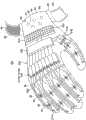
图1是表示本发明中的穿着式动作辅助装置的实施例1的俯视图。Fig. 1 is a plan
图2A是从侧面观察实施例1的穿着式动作辅助装置10的外观图。FIG. 2A is an external view of the wearable
图2B是表示使用实施例1的穿着式动作辅助装置10把持物体时的动作状态的外观图。FIG. 2B is an external view showing a motion state when an object is grasped using the wearable
图3A是表示线状部件50及驱动部40的结构的模式图。FIG. 3A is a schematic diagram showing the configuration of the
图3B是沿图3A中A-A线的纵剖面剖视图。Fig. 3B is a longitudinal sectional view along line A-A in Fig. 3A.
图3C是表示线状部件做弯曲动作时的状态的图。Fig. 3C is a diagram showing a state when the linear member is bent.
图4是表示包括控制单元70的控制系及充电系统的概略结构的模式图。FIG. 4 is a schematic diagram showing a schematic configuration of a control system and a charging system including the
图5是实施例1的控制部100A的系统图。FIG. 5 is a system diagram of a
图6是表示由生物电位信号生成各控制信号的过程的图。FIG. 6 is a diagram showing a process of generating each control signal from a biopotential signal.
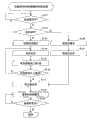
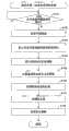
图7A是用于说明控制部100A执行的控制处理步骤的一个例子的第一部分的流程图。FIG. 7A is a flowchart illustrating a first part of an example of the control processing procedure executed by the
图7B是用于说明控制部100A执行的控制处理步骤的一个例子的第二部分的流程图。FIG. 7B is a flowchart illustrating a second part of an example of the control processing procedure executed by the
图8是模式表示实施例2的控制部100B的信号处理的系统图。FIG. 8 is a system diagram schematically showing signal processing by the
图9是将伸开手指(任务A)、把持东西(任务B)、弯曲手指(任务C)及握手(任务D)进行模式示例的图。Fig. 9 is a diagram showing pattern examples of stretching fingers (task A), holding something (task B), bending fingers (task C) and shaking hands (task D).
图10A是表示数据库300中存储的各任务及各阶段的模式图。FIG. 10A is a schematic diagram showing each task and each stage stored in the
图10B是表示通过将物理量与基准参数进行比较而对穿着者将要进行的任务及其中的阶段进行推定的过程的模式图。FIG. 10B is a schematic diagram showing a process of estimating a task to be performed by a wearer and a stage thereof by comparing a physical quantity with a reference parameter.
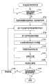
图11A是表示实施例2的控制部100B执行的控制处理的一个例子的第一部分的流程图。11A is a flowchart showing a first part of an example of control processing executed by the
图11B是表示实施例2的控制部100B执行的控制处理的一个例子的第二部分的流程图。11B is a flowchart showing a second part of an example of control processing executed by the
图12是模式表示实施例3的控制部100C的控制系的信号处理的系统图。FIG. 12 is a system diagram schematically showing signal processing in the control system of the
图13A是表示实施例3的控制部100C执行的控制处理的一个例子的第一部分的流程图。13A is a flowchart showing a first part of an example of control processing executed by the
图13B是表示实施例3的控制部100C执行的控制处理的一个例子的第二部分的流程图。13B is a flowchart showing a second part of an example of control processing executed by the
图14是模式表示实施例4的控制部100D的控制系的信号处理的系统图。FIG. 14 is a system diagram schematically showing signal processing in the control system of the
图15A是表示实施例4的控制部100D执行的控制处理的一个例子的第一部分的流程图。15A is a flowchart showing a first part of an example of control processing executed by the
图15B是表示实施例4的控制部100D执行的控制处理的一个例子的第二部分的流程图。15B is a flowchart showing a second part of an example of control processing executed by the
图16是模式表示实施例5的控制部100E的控制系的信号处理的系统图。FIG. 16 is a system diagram schematically showing signal processing in the control system of the
图17A是用于对实施例5的控制部100E执行的控制处理的一个例子的第一部分的步骤进行说明的流程图。17A is a flowchart for explaining the steps of the first part of an example of the control process executed by the
图17B是用于对实施例5的控制部100E执行的控制处理的一个例子的第二部分的步骤进行说明的流程图。FIG. 17B is a flowchart for explaining the steps of the second part of an example of the control process executed by the
图18是模式表示实施例6的控制部100F的控制系的信号处理的系统图。FIG. 18 is a system diagram schematically showing signal processing in the control system of the
图19是用于对实施例6的控制部100F执行的控制处理的步骤进行说明的流程图。FIG. 19 is a flowchart for explaining the procedure of control processing executed by the
图20是表示进行初期设定的初次校准的控制步骤的流程图。FIG. 20 is a flowchart showing a control procedure for performing initial calibration for initial settings.
图21是表示通过单一动作(1次动作)的再设定校准的控制步骤的流程图。Fig. 21 is a flowchart showing a control procedure of reset calibration by a single operation (one operation).
图22是表示再设定模式2的校准控制处理的控制步骤的流程图。FIG. 22 is a flowchart showing a control procedure of calibration control processing in
图23是表示变形例1的穿着式动作辅助装置10A的立体图。FIG. 23 is a perspective view showing a wearable
图24A是从侧面观察变形例1的穿着式动作辅助装置10A的外观图。FIG. 24A is an external view of a wearable
图24B是表示使用变形例1的穿着式动作辅助装置10A把持物体时的动作状态的外观图。FIG. 24B is an external view showing a motion state when an object is grasped using the wearable
图25A是表示致动器510的内部构造的横剖面剖视图。FIG. 25A is a cross-sectional view showing the internal structure of the
图25B是沿图25A的D-D线的纵剖面剖视图。Fig. 25B is a longitudinal sectional view taken along line D-D of Fig. 25A.
图26是表示变形例2的穿着式动作辅助装置10B的立体图。FIG. 26 is a perspective view showing a wearable
图27A是从侧面观察变形例2的穿着式动作辅助装置10B的外观图。FIG. 27A is an external view of a wearable
图27B是表示使用变形例2的穿着式动作辅助装置10B把持物体时的动作状态的外观图。FIG. 27B is an external view showing a motion state when an object is grasped using the wearable
图28是表示变形例3的穿着式动作辅助装置10C的立体图。FIG. 28 is a perspective view showing a wearable
图29A是从侧面观察变形例3的穿着式动作辅助装置10C的外观图。FIG. 29A is an external view of a wearable
图29B是表示使用变形例3的穿着式动作辅助装置10C把持物体时的动作状态的外观图。FIG. 29B is an external view showing a motion state when an object is grasped using the wearable
图30是表示变形例4的穿着式动作辅助装置10D的立体图。FIG. 30 is a perspective view showing a wearable
图31A是表示对变形例4的穿着式动作辅助装置10D的手指插入部的一部分剖视的图。31A is a diagram showing a partial sectional view of a finger insertion portion of a wearable
图31B是表示变形例4的穿着式动作辅助装置10D的手指插入部被弯曲时的动作状态的图。FIG. 31B is a diagram illustrating an operating state of a wearable
其中,附图标记说明如下:Wherein, the reference signs are explained as follows:
10、10A~10D穿着式动作辅助装置;20、20A~20D动作辅助手套;21、21A~21D手指插入部;22开口;24手腕部;30被驱动部;32、34、36环扎环;40、510、710驱动部;40a~40j驱动机构;42转动部件;44电动马达;50、50a~50j、500、700、800线状部件;51筒状体;52、53线材(wire);54帽;55中空部;57上部空间;58下部空间;59中部空间;60生物信号检测部;61~65生物电位传感器;70、70A、70C、70D控制单元;80、82带;84钩环扣;90施力部件;94转矩传感器;96角度传感器;100、100A~100F控制部;102存储器;104显示器;124、610充电式电池;130应力传感器;140充电器;200生物电位处理部件(生物信号处理部件);202放大器;204高频带通滤波器;206中频带通滤波器;212随意控制部件;220驱动电流生成部件;300数据库;310自律控制部件;320控制信号合成部件;400校准数据库;410阶段确定部件;420差值导出部件;430参数校正部件;440校准控制部件;450负荷产生部件;502中空路径;510a~510j致动器;520流动体;530外壳;540珀耳帖元件(Peltier device);612太阳电池;600物体检测传感器;710a~710j线性马达(linear motor);810施加电压切换电路;801、802电极层;803驱动层10. 10A~10D wearable motion assisting devices; 20. 20A~20D motion assisting gloves; 21. 21A~21D finger insertion parts; 22 openings; 24 wrist parts; 30 driven parts; 32, 34, 36 cerclage rings; 40, 510, 710 driving part; 40a~40j driving mechanism; 42 rotating parts; 44 electric motor; 50, 50a~50j, 500, 700, 800 linear parts; 54 cap; 55 hollow part; 57 upper space; 58 lower space; 59 middle space; 60 biological signal detection part; buckle; 90 force applying component; 94 torque sensor; 96 angle sensor; 100, 100A~100F control unit; 102 memory; 104 display; 124, 610 rechargeable battery; (biological signal processing part); 202 amplifier; 204 high-frequency band-pass filter; 206 intermediate-frequency band-pass filter; 212 random control part; 220 driving current generation part; 300 database; 310 self-discipline control part; 400 Calibration Database; 410 Phase Determination Part; 420 Difference Value Derivation Part; 430 Parameter Correction Part; 440 Calibration Control Part; 450 Load Generation Part; 502 Hollow Path; Peltier device; 612 solar cell; 600 object detection sensor; 710a ~ 710j linear motor (linear motor); 810 applied voltage switching circuit; 801, 802 electrode layer; 803 drive layer
具体实施方式Detailed ways
下面结合附图对本发明的实施方式进行说明。Embodiments of the present invention will be described below in conjunction with the accompanying drawings.
(实施例1)(Example 1)
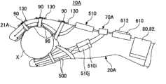
图1是表示本发明中的穿着式动作辅助装置的实施例1的俯视图。图2A是从侧面观察实施例1的穿着式动作辅助装置10的外观图。图2B是表示使用实施例1的穿着式动作辅助装置10把持物体时的动作状态的外观图。如图1及图2所示,穿着式动作辅助装置10由具有插入有穿着者各手指的手指插入部21的动作辅助手套20所构成,与通常的手套一样被穿着。动作辅助手套20中,设置有被驱动部30、驱动部40(40a~40j)、线状部件50(50a~50j)、生物信号检测部60及控制单元70。Fig. 1 is a plan
由于即使在例如操作者用于进行手的动作的神经系统麻痹时,根据由生物信号检测部60所检测出的生物信号,动作辅助手套20的各手指插入部21也可被驱动,因此穿着式动作辅助装置10能够根据来自控制单元70的控制信号进行辅助,使得各根手指沿伸展方向或弯曲方向进行动作。另外,穿着式动作辅助装置10还能够用于进行手指的动作训练的康复训练(rehabilitation:机能恢复训练)。Since each
动作辅助手套20以紧贴穿着者的手的方式被形成为配合手的大小的立体形状。另外,动作辅助手套20是将外侧动作辅助手套和内侧动作辅助手套作为一体缝入的双层构造,例如外侧动作辅助手套由牛皮或合成皮革等具有柔软性及耐久性的材质形成,内侧动作辅助手套以紧贴手的表面(皮肤)的方式由薄橡胶材料形成。The
另外,在动作辅助手套20的各手指插入部21的指尖部分上,设置有使穿着者的手指尖露出的开口22。如图2A所示,由于可使指尖的皮肤与所把持的物体直接接触,所以穿着者能够通过指尖的触感识别所把持的物体X。In addition,
在动作辅助手套20的手背侧上,沿各手指插入部21的延伸方向配置多个线状部件50(50a~50j)。多个线状部件50的一端与动作辅助手套20的各手指插入部21的尖端上设置的被驱动部30连接。多个线状部件50为传递驱动力的部件,但其与金属部件等相比被大幅度轻量化,能够减轻穿着者的负担。On the back of the hand of the
被驱动部30形成为环状,以紧贴各手指插入部21的尖端的外周的方式被配置在开口22的外侧。另外,多个线状部件50通过被缠绕在手指关节上的环扎环32、34、36被环扎在动作辅助手套20的各手指插入部21的外侧。在环扎环32、34、36上保持有检测各手指关节的角度的角度传感器96。在各手指关节的角度变化时,角度传感器96向控制单元70输出基于角度变化的检测信号。The driven
再有,多个线状部件50被缝合在动作辅助手套20的各手指插入部21的外侧或外侧动作辅助手套的内侧。因此,随着多个线状部件50在沿伸展方向或弯曲方向动作,动作辅助手套20的各手指也与线状部件50作为一体沿伸展方向或弯曲方向动作。In addition, a plurality of
如图2A及图2B所示,在位于各手指插入部21的各手指关节的外侧的部分,设置有施力部件90。作为施力部件90,例如由螺旋弹簧或橡胶材料等弹性部件构成,一端相对手指关节与手腕侧连接,另一端相对手指关节与指尖侧连接。因此,动作辅助手套20的各手指插入部21的覆盖手指关节的表面上,被赋予施力部件90的施加力以使手指插入部21趋向伸展,施加力作为各手指关节的伸展动作(从图2B所示把持状态到图2A所示开放状态的动作)的辅助力产生作用。As shown in FIGS. 2A and 2B , an urging
在此需要说明的是,施力部件90也可以以沿弯曲各手指关节的方向施力的方式安装。在以这种方式安装施力部件90时,由于施力部件90被配置在手的平侧,所以最好使用例如将手的平侧接触到的物体的触感进行传递的将橡胶材料加工成扁平状的弹性部件。It should be noted here that the urging
另外,施力部件90的连接部分上,设置有应力传感器130。应力传感器130由例如应变计(strain gauge)等构成,将基于施力部件90根据手指关节的动作伸缩时的应力变化的检测信号输出到控制单元70。In addition, a
驱动部40配置在动作辅助手套20的手背侧,是使线状部件50沿手指关节的动作方向进行伸展动作或弯曲动作的驱动部件,例如具有使在线状部件50内部贯穿插入的线材(wire)沿伸展方向或弯曲方向移动的驱动机构40a~40j。在本实施例中,在各手指插入部21的手背侧或侧面的两侧各配置有2条线状部件50a~50j,并且各手指插入部21上各自并排设置有一对驱动机构40a~40j。The driving
生物信号检测部60具有多个生物电位传感器61~65,并被配置在动作辅助手套20的手腕部24的内侧。生物电位传感器61~65分别由检测使手的各根手指动作的生物信号(例如肌肉电位信号或神经传递信号或脑波等)的电极所构成。另外,动作辅助手套20的手腕部24的两侧设置有从外侧缠绕并紧贴穿着者的手的带80、82。在带80、82上设置有用于在重叠部分相互卡固的钩环扣(hook-and-loop fastener)84。因此,在调节带80、82的在动作辅助手套20的手腕部24的外侧重叠部分的长度后,能够将带80、82的钩环扣84相对并使生物电位传感器61~65紧贴在穿着者的皮肤上。生物电位传感器61~65检测出穿着者将要使手指动作的生物信号,并根据生物信号输出检测信号。The
控制单元70根据由生物信号检测部60的生物电位传感器61~65所检测出的生物信号进行演算处理(稍后详述),并向驱动机构40a~40j输出驱动控制信号。另外,控制单元70具有下述进行演算处理的控制部、存储器及充电式电池。The
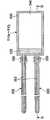
这里,对线状部件50及驱动部40的结构进行说明。图3A是表示线状部件50及驱动部40的结构的模式图。如图3所示,线状部件50具有筒状体51、线材52、53及帽54。筒状体51由具有可挠性的树脂材料形成为筒状。另外,筒状体51的内侧形成有线材52、53贯穿插入的中空部55、外侧形成有根据伸展动作或弯曲动作伸缩的凹部和凸部相互连续的波纹管(bellows)状部56。Here, the structure of the
再有,在筒状体51的尖端与中空部55连通的开口被帽54闭塞。帽54由金属材料所形成,其壁部54a被各线材52、53的一端贯穿插入且通过焊着作为一体被结合。另外,帽54的周缘部54b与筒状体51的端部粘结或焊着并成为一体。Furthermore, an opening communicating with the
图3B是沿图3A中A-A线的纵剖面剖视图。如图3B所示,筒状体51的剖面形状为由四角形构成的矩形,通过在中空部55横向架设的多个横架部件55a被分隔成上部空间57、下部空间58及中部空间59。Fig. 3B is a longitudinal sectional view along line A-A in Fig. 3A. As shown in FIG. 3B , the cross-sectional shape of the
上部空间57上架设有2条线材52,下部空间58架设有2条线材53。在本实施例中,共计4条线材52、53被以对于筒状体51上下对称的方式被配置。另外,由于筒状体51的外观形状为四角形,所以通过使其下表面与动作辅助手套20的外表面向抵接,可以配合动作方向决定其位置。Two
如图3A所示,各线材52、53的另一端与驱动部40的转动部件42连接。本实施例中的转动部件42形成为椭圆形状,在其长径部的周缘部的最远离的位置与各线材52、53的另一端连接。在此需要说明的是,由于分别被配置的2条线材52、53与一个转动部件42的两面连接,所以根据转动部件42的转动角度同时进行动作。再有,贯通转动部件42的中心部的轴与电动马达44的输出轴连接。因此,驱动部40通过使转动部件42以转动方向切换的方式转动,使线材52和线材53向反方向移动从而能够将驱动力高效地传递到动作辅助手套20的各手指插入部21。线材52、53中进行拉力作用的一方作为传递使手指插入部21动作的驱动力的传递部件进行动作。另外,在电动马达44输出轴的另一端,设置有检测马达转矩的转矩传感器94。As shown in FIG. 3A , the other ends of the
例如当转动部件42沿顺时针方向(B方向)转动时,上侧的线材52沿拉拽方向进行动作,下侧的线材53沿返回方向进行动作。由此,线状部件50进行动作使得筒状体51返回直线状。因此,线状部件50的伸展动作被传递到动作辅助手套20的各手指插入部21,能够使穿着者的各手指向打开状态(参见图1及图2A)动作。For example, when the rotating
另外,如图3A中一点虚线所示,转动部件42沿逆时针方向(C方向)转动时,上侧的线材52沿返回方向进行动作,下侧的线材53沿拉拽方向进行动作。由此,如图3C所示,线状部件50的筒状体51向弯曲状态动作。因此,线状部件50的弯曲动作被传递到动作辅助手套20的各手指插入部21,能够使穿着者的各手指向把持状态(参见图2B)动作。In addition, as shown by a dotted line in FIG. 3A , when the rotating
在本实施例中,由于向伸展方向或弯曲方向驱动上述线材52、53时的行程(stroke:动作距离)是由形成为椭圆形的转动部件42的长径尺寸所决定,所以通过加大转动部件42的长径尺寸,能够将线状部件50的从弯曲动作到伸展动作的行程设定得更大。另外,通过设置代替转动部件42的齿轮机构及缠绕线材52、53的滑轮等驱动机构并调节滑轮的转动量,能够将线状部件50的动作行程适当地调节。In this embodiment, since the stroke (stroke: action distance) when driving the above-mentioned
这样,穿着式动作辅助装置10通过根据来自控制单元70的驱动控制信号使线状部件50沿手指插入部21的关节的动作方向伸展或弯曲,能够将驱动部40的驱动力进行传递以使穿着者的手指关节进行动作,因此能够实现轻量化,还能够减轻穿着者的负担。In this way, the wearable
图4是表示包括控制单元70的控制系及充电系统的概略结构的模式图。如图4所示,控制单元70具有控制部100、存储器102、显示器104及充电式电池124。FIG. 4 is a schematic diagram showing a schematic configuration of a control system and a charging system including the
由生物电位传感器61~65检测出的生物信号、由转矩传感器94检测出的电动马达44的转矩检测信号、由角度传感器96检测出的各手指关节的角度检测信号以及由应力传感器130检测出的应力检测信号被输入到控制部100。控制部100读入在存储器102中存储的各控制程序及各参数,并根据来自转矩传感器94、角度传感器96及应力传感器130的检测信号进行演算处理并将动作辅助手套20的动作状态在显示器104上显示。充电式电池124与充电单元122的次级线圈126连接,并由充电器140定期充电。The biological signals detected by the
充电器140具有使次级线圈126产生电磁感应电流的初级线圈142。因此,通过使初级线圈142接近动作辅助手套20而由于电磁感应使充电单元122的次级线圈126产生次级电流。由此,动作辅助手套20的充电式电池124在穿着状态下仍能够进行充电,并即使在穿着者使用时也能够充电。The
图5是实施例1的控制部100A的系统图。如图5所示,控制部100A是图4中所示的控制部100的一个例子,由通过从存储器102读入控制程序而进行下述各控制处理的计算机构成。FIG. 5 is a system diagram of a
在本实施例中,控制部100A具有根据由生物电位传感器61~65检测出的生物电位取得指令信号的生物电位处理部件(生物信号处理部件)200、根据神经传递信号b及肌肉电位信号c对电动马达44的驱动进行控制的随意控制部件212及将基于由随意控制部件212输出的控制信号的驱动电流供给到电动马达44的驱动电流生成部件220。In this embodiment, the
随意控制部件212如下所述根据来自生物电位处理手段200的指令信号将控制信号输出到驱动电流生成部件220,该生物电位处理手段200根据按照穿着者的意思使各根手指动作时产生的生物电位信号a来生成神经传递信号b及肌肉电位信号c。驱动电流生成手段220根据来自随意控制部件212的控制信号来生成驱动电流并输出到电动马达44。The
生物电位传感器61~65检测在上臂的内侧产生的生物电位信号a并输出到生物电位处理部件200。生物电位处理部件200从生物电位信号a中抽出神经传递信号b及肌肉电位信号c并输入到随意控制部件212。随意控制部件212根据由按照穿着者的意思使穿着动作辅助手套20的手的各根手指动作时所产生的生物电位信号a而得到得神经传递信号b及肌肉电位信号,生成随意控制信号d1。The
换言之,随意控制部件212使用生物电位信号a中包含的神经传递信号b及肌肉电位信号c,生成随意控制信号d1,该随意控制信号d1用于使电动马达44产生按照穿着者的意思的动力。作为随意控制部件212上的控制原则,可应用比例控制。通过比例控制随意控制信号d1与驱动电流e达成比例关系。再有,由电动马达44的特性,驱动电流值与电动马达44的产生转矩值达成比例关系。在此需要说明的是,作为随意控制部件212上的控制原则,也可应用比例控制与微分控制和/或积分控制的组合。In other words, the
例如,当穿着者要使关节20动作时,生物电位传感器61~65直接检测出使手指等做的生物电位,将基于检测出的生物电位的生物电位a输出到生物电位处理部件200。这样,由于生物电位传感器61~65从由于带80、82的紧固而被动作辅助手套20的手腕部24紧贴的穿着者的手腕直接检测出生物电位信号a,因此检测精度高,并且即使是微弱的信号也能够准确的检测出。For example, when the wearer moves the joint 20 , the
从生物电位处理部件200被输入由神经传递信号b和肌肉电位信号c构成的指令信号的随意控制部件212,根据神经传递信号b和肌肉电位信号c生成控制信号d1并输出到驱动电流生成部件220。The
驱动电流生成部件220根据来自随意控制部件212的控制信号d1生成马达驱动电流e并供给到电动马达44。由此,电动马达44通过马达驱动电流e的供给而使转动部件42向伸展方向或弯曲方向转动。因此,使筒状体51的中空部55中架设的线材52、52移动以使动作辅助手套20的线状部件50进行伸展动作或弯曲动作。The drive
图6是表示由生物电位信号生成各控制信号的过程的图。如图6所示,由生物电位传感器检61~65测出的生物电位信号a具有神经传递信号b及肌肉电位信号c。神经传递信号b也可被称之为意思传递信号,与肌肉电位信号的最先范围重叠。神经传递信号b的频率一般比肌肉电位信号c的频域高,可使用不同的带通滤波器进行分离。FIG. 6 is a diagram showing a process of generating each control signal from a biopotential signal. As shown in FIG. 6 , the biopotential signal a detected by the
在将生物电位信号a经放大器202放大后,可通过例如33Hz~数KHz的高频带通滤波器204将神经传递信号b抽出。另外,在将生物电位信号a经放大器202放大后,可通过例如33Hz~500Hz的中频带通滤波器206将肌肉电位信号c抽出。在此需要说明的是,在图6中,各滤波器204、206并不限定于并联,也可将两滤波器204、206串联。After the biopotential signal a is amplified by the
另外,神经传递信号b也有可能不仅在肌肉电位信号的最先范围重叠,还有可能在最先范围之后也重叠。这时,可以只使用神经传递信号b的最先范围生成下述的脉冲电流。In addition, the neurotransmission signal b may overlap not only in the first range of the myoelectric potential signal but also after the first range. In this case, the following pulse current can be generated using only the first range of the neurotransmission signal b.
对于神经传递信号b及肌肉电位信号c进行平滑处理(去除噪声的平滑处理)。将来自生物信号处理部件200的信号进行平滑处理之后的到的控制信号作为输入,由驱动电流生成部件220生成。Smoothing processing (smoothing processing for removing noise) is performed on the neurotransmission signal b and the myoelectric potential signal c. The control signal obtained by smoothing the signal from the biological
由于神经传递信号b在时间轴上的宽度窄,所以即便只进行平滑处理其也呈脉冲形状,根据该神经传递信号b由驱动电流生成部件220所生成的电流也呈脉冲形状。另外,根据神经传递信号b得到得电流(脉冲电流)e1呈矩形波形状。另一方面,由于肌肉电位信号c在时间轴上得宽度宽,所以经平滑处理呈与实际肌肉电位成比例得山形状,根据该肌肉电位信号c由驱动电流生成部件220所生成的电流e2也成山形状。Since the nerve transmission signal b has a narrow width on the time axis, it has a pulse shape even if it is only smoothed, and the current generated by the drive
当将基于神经传递信号b生成的脉冲电流e1和基于肌肉电位信号c成比例生成的电流e2的总电流(随意控制信号)e供给到电动马达44时,电动马达44产生与该总电流e成比例的大小的转矩。输入到电动马达44的各电流e、e1、e2的大小可根据穿着者进行动作时的感觉适当设定。When the
这里,由于总电流被设定成充分大的电流,所以电动马达44按照穿着者的动作意思被及时的驱动,穿着者能够毫无别扭感地进行按照自己的意思的各手指关节的动作。在此需要说明的是,尽管将脉冲电流e1特别放大表示,但这是为了强调其作用,并非是表示实际的脉冲电流与从肌肉电位信号所得到的驱动电流e2的关系。Here, since the total current is set to a sufficiently large current, the
这里,对图5中所示上述控制系统中的控制部100a执行的控制处理的步骤,参照图7A及图7B的流程图进行说明。控制部100A读入存储器102中存储的控制程序后执行图7的控制处理。Here, the procedure of the control process executed by the control unit 100a in the control system shown in FIG. 5 will be described with reference to the flowcharts of FIGS. 7A and 7B. The
在图7A的SA11,如果控制单元70的电源开关被操作为开,则进到SA12,检查是否接收到由生物电位传感器61~65检测出的生物电位信号a。在此,当穿着者要以自己的意思使各手指关节动作时,由于由生物电位传感器61~65检测出生物电位信号a,所以进到SA13的处理。In SA11 of FIG. 7A , if the power switch of the
在SA13,根据由生物电位传感器61~65检测出的生物电位信号a取得神经传递信号b及肌肉电位信号c(生物电位处理部件)。接着,进到S14,根据神经传递信号b生成脉冲电流e1,并且根据肌肉电位信号c生成电流e2(驱动电流生成部件)。In SA13, the nerve transmission signal b and the muscle potential signal c are obtained from the biopotential signal a detected by the
接着在SA15,检查基于神经传递信号b的脉冲电流e1是否在电动马达44的可驱动开始电流的下限值It以上。在该SA15中,脉冲电流e1不在电动马达44的可驱动开始电流的下限值It以上时(“否”的情况下),进到SA16,放大脉冲电流e1以使脉冲电流e1达到可驱动开始电流的下限值It以上。Next, at SA15 , it is checked whether the pulse current e1 based on the nerve transmission signal b is equal to or greater than the lower limit value It of the drivable start current of the
另外,在S15中,脉冲电流e1在电动马达44的可驱动开始电流的下限值It以上时(“是”的情况下),进到图7B的SA17,生成基于脉冲电流e1的指令信号。接着,在SA18,将基于肌肉电位信号c的驱动电流e2输出到电动马达44。由此,动作辅助手套20的各线状部件50进行伸展动作或弯曲动作。Also, in S15, when the pulse current e1 is equal to or greater than the lower limit value It of the drivable start current of the electric motor 44 (in the case of YES), the process proceeds to SA17 in FIG. 7B to generate a command signal based on the pulse current e1. Next, at SA18 , the drive current e2 based on the myoelectric potential signal c is output to the
接着在SA19,随着动作辅助手套20的各线状部件50的动作各指关节进行动作,并检查是否接收到转矩传感器94、角度传感器96及应力传感器130(物理量传感器)的传感器信号f。Next, in SA19, each knuckle moves according to the movement of each
接着,进到SA20,检查随着由电动马达44的驱动力的各手指关节的动作而由应力传感器130检测出的检测到应力是否在预先设定的容许值以下。该容许值根据施力部件90的施加力的强度而被经选择地设定。由此,电动马达44的驱动力被控制以使手指关节不会勉强动作,另外防止了由于电动马达44的驱动力致使的手指关节的损伤。Next, proceeding to SA20, it is checked whether the detected stress detected by the
因此,在SA20中,当由应力传感器130检测出的各手指关节的检测到应力在预先设定的容许值以下时(“是”的情况下),进到S21,在显示器104上显示各物理量传感器(转矩传感器94、角度传感器96及应力传感器130)的检测值(物理信息)及生物电位信号。由此,穿着者能够由显示器104的显示对各手指关节的动作状态(由于各线状部件50的驱动力及驱动方向)进行识别。Therefore, in SA20, when the detected stress of each finger joint detected by the
另外,在上述SA20中,当由应力传感器130检测出的各手指关节的检测到应力不在预先设定的容许值以下时(“否”的情况下),进到SA22,将供给到电动马达44的驱动电流e下调例如10%。在此需要说明的是,驱动电流e的下调幅度可以设定为任意值,例如可以在1~10%的范围内被设定更改。In addition, in the above-mentioned SA20, when the detected stress of each finger joint detected by the
接着,在SA23,将上述被限制的驱动电流输出到电动马达44。由此,控制电动马达44被控制产生不超过各手指关节强度的被限制的转矩及转动角。Next, at SA23 , the aforementioned limited drive current is output to the
接着,进到SA24,将被限制的驱动电流的数据显示在显示器104上。之后,返回SA19,检查随着各手指关节的动作是否接收到各物理量传感器(转矩传感器94、角度传感器96及应力传感器130)的传感器信号f并进行之后的处理。Next, proceed to SA24, and display the data of the limited drive current on the
通过重复进行SA19、SA20、SA22~SA24的控制处理,防止了电动马达44被控制成其驱动力达到容许值以下并传递过剩的转矩的情况。By repeating the control processing of SA19 , SA20 , and SA22 to SA24 , it is prevented that the
该SA11~SA24的处理被重复执行直到控制单元70的电源开关被关闭。由此,电动马达44以进行按照穿着者意思的动作的方式被驱动控制。The processes of SA11 to SA24 are repeatedly executed until the power switch of the
(实施例2)(Example 2)
图8是模式表示实施例2的控制部100B的信号处理的系统图。在此需要说明的是,在图8中,对于与上述实施例1的图4相同部分附上相同的符号并省略其说明。FIG. 8 is a system diagram schematically showing signal processing by the
图8所示的实施例2的控制部100b具有生物电位处理部件200、随意控制部件212、数据库300及驱动电流生成部件220。在此需要说明的是,由于动作辅助手套20与上述实施例1为相同结构,所以将其说明省略。另外,图8的控制部100B是图3的控制部100的一个例子。The control unit 100 b of the second embodiment shown in FIG. 8 has a
控制部100B的数据库300存储有用于对于所有任务(task)的所有阶段(phase)根据经验求出穿着者的各手指关节的转动角及角速度等的基准参数(基准的转动角及角速度等)。在进行动作辅助手套20(参见图1至图3)的电动马达44的随意控制时,随意控制部件212根据关于穿着者的各手指关节的动作的物理量从数据库300推定任务及阶段,并使电动马达44产生出达到对应推定的阶段的助力(power assist)率的驱动力。The
这里,对上述任务(task)及其阶段(phase)进行说明。任务是对穿着者的各手指关节的动作模式进行分类的单位,阶段是构成各任务的一连串的最小动作单位。Here, the above-mentioned task (task) and its phase (phase) will be described. A task is a unit for classifying movement patterns of each finger joint of the wearer, and a stage is a series of minimum movement units constituting each task.
图9是作为各手指的基本动作,将伸开手指(任务A)、把持东西(任务B)、弯曲手指(任务C)及握手(任务D)进行模式示例的图。在此需要说明的是,如本实施例中图1~3所示,尽管是对穿着者实际穿着动作辅助手套20的情况进行说明,但在这里为了说明的方便,以上述各手指的动作为例进行说明。FIG. 9 is a diagram showing pattern examples of stretching fingers (task A), grasping objects (task B), bending fingers (task C) and shaking hands (task D) as basic actions of each finger. What needs to be explained here is that, as shown in FIGS. 1 to 3 in this embodiment, although the description is given to the situation in which the wearer actually wears the
在图9中,各任务由上述阶段构成,例如把持东西的任务B由各手指伸齐的阶段B1、各手指的第1关节弯曲的阶段B2、各手指的第1、第2关节弯曲的阶段B3及各手指的第1、第2、第3关节弯曲的阶段B4构成。In FIG. 9 , each task is composed of the above-mentioned stages. For example, the task B of grasping an object consists of stage B1 in which each finger is straightened, stage B2 in which the first joint of each finger is bent, and the stage in which the first and second joints of each finger are bent. B3 and stage B4 in which the first, second, and third joints of each finger are bent.
将这样一连串的阶段B1~B4称为阶段序列(phase sequence)。对穿着者的各手指关节动作辅助的适合的动力在每个阶段各不相同。因此,通过赋予根据各阶段而各不相同的助力率PAR1、PAR2、PAR3及PAR4,是的能够针对每个阶段进行最适当的动作辅助。Such a series of phases B1 to B4 is called a phase sequence. The appropriate power to assist the movement of each finger joint of the wearer is different for each stage. Therefore, by giving the assist ratios PAR1 , PAR2 , PAR3 , and PAR4 that differ for each stage, it is possible to perform optimal motion assistance for each stage.
通过分析穿着者的各手指关节的动作,发现在各阶段中的各手指关节的转动角及角速度,动作速度及加速度等是固定的。例如,穿着者的典型的手指动作模式是固定的,以该动作模式使动作辅助手套20进行动作时最能感觉到自然。因此,可以对于所有任务的所有阶段根据经验求出穿着者的各手指关节的转动角及角速度等,并将其作为基准参数(基准的转动角及角速度等)存储在数据库300中。By analyzing the movement of each finger joint of the wearer, it is found that the rotation angle and angular velocity, movement speed and acceleration of each finger joint in each stage are fixed. For example, the typical finger motion pattern of the wearer is fixed, and the
图10A是表示数据库300中存储的各任务及各阶段的模式图。图10B是表示通过将物理量与基准参数进行比较而对穿着者将要进行的任务及其中的阶段进行推定的过程的模式图。图10A、图10B中所示的任务及阶段即是图9中所示的任务及阶段。示例的任务A、任务B、任务C…分别由一连串的阶段(阶段A1、阶段A2、阶段A3…、阶段B1、阶段B2、阶段B3…等)构成。FIG. 10A is a schematic diagram showing each task and each stage stored in the
当穿着者开始各手指关节的动作时,将通过由作为物理量传感器的角度传感器96、应力传感器130检测出的传感器信号所得到得各种物理量得实测值与数据库300中存储得基准参数相比较。该比较由图10B中的图表概略表示。在该图表中,表示出了各手指的第1关节得转动角θ1及角速度θ1’、各手指的第2关节的转动角θ2及角速度θ2’、以及各手指的第3关节的转动角θ3及角速度θ3’,当然,比较的物理量不限定于此。When the wearer starts to move each finger joint, the actual measurement values of various physical quantities obtained from the sensor signals detected by the
以一定的短时间间隔比较实测的物理量与基准参数。该比较处理对所有的任务(A、B、C…)中的一连串的阶段进行。换言之,将如图10A的右侧表所示的所有的阶段(A1、A2、A3…、B1、B2、B3…、C1、C2、C3…)以矩阵(matrix)状抽出,与实测的物理量进行比较。The measured physical quantity is compared with the reference parameter at certain short time intervals. This comparison process is performed for a series of stages in all the tasks (A, B, C, . . . ). In other words, all stages (A1, A2, A3..., B1, B2, B3..., C1, C2, C3...) shown in the table on the right side of Figure 10A are extracted in a matrix form, and the actual measured physical quantities Compare.
如图10B的图表所示,如果分别在例如时间t1、t2、t3进行比较,则能够确定具有与实测的物理量全部一致的基准参数的阶段。为了排除一致的误差,也可以在多个时间上确认一致后,进行阶段的确定。例如在图示的例子中,如果实测值在多个时间上与阶段A1的基准参数一致时,则可得知现在的动作是阶段A1的动作。当然,具有与实测值一致的基准参数的阶段,不限定于任务的最初的阶段(A1、B1、C1等)。As shown in the graph of FIG. 10B , for example, by comparing at times t1 , t2 , and t3 , it is possible to identify a stage having reference parameters that all match the measured physical quantities. In order to eliminate the coincidence error, it is also possible to determine the stage after confirming the coincidence at multiple times. For example, in the illustrated example, if the actual measurement value coincides with the reference parameter of the stage A1 over a plurality of times, it can be known that the current operation is the operation of the stage A1. Of course, the phases having reference parameters that match the actual measurement values are not limited to the initial phases (A1, B1, C1, etc.) of the task.
图11A及图11B是用于说明实施例2的控制部100B执行的控制处理的步骤的流程图。控制部100B读入存储在存储器102中的控制程序并执行图11A及图11B的控制处理。11A and 11B are flowcharts for explaining the procedure of control processing executed by the
在此需要说明的是,由于图11A及图11B的SB11、SB12及SB14~SB17、SB24~SB29实际上与图7的SA11~SA16、SA19~SA24为相同的处理,所以将其说明省略,在此主要对SB13、SB18~SB23的处理进行说明。It should be noted here that since SB11, SB12, SB14-SB17, SB24-SB29 in FIG. 11A and FIG. 11B are actually the same process as SA11-SA16, SA19-SA24 in FIG. This section mainly describes the processing of SB13 and SB18 to SB23.
在如图11A所示的SB13中,检查是否收到检测出随着各手指关节的动作产生的各物理量(转矩、转动角、应力)的转矩传感器94、角度传感器96、应力传感器130的检测信号的无线信号。在SB13中,如果接收到转矩传感器94、角度传感器96、应力传感器130的检测信号,则进到SB14。In SB13 as shown in FIG. 11A, it is checked whether the signals from the
在SB18,依次比较由转矩传感器94、角度传感器96、应力传感器130检测出的物理量(实测值)与数据库300中存储的各阶段的基准参数。如参照图10A、图10B所说明的,由于所有的任务及每个任务各自的阶段以矩阵状方式存在,所以将物理量的实测值与各阶段的基准参数,以例如A1、A2、A3…、B1、B2、B3…、C1、C2、C3…的顺序依次进行比较。由于数据库300中存储的基准参数与所有的任务及阶段(以下只称之为“任务/阶段”)之间不重复的设定,所以能够将具有与物理量的实测值相一致的基准参数的任务及阶段抽出。In SB18 , the physical quantities (actually measured values) detected by the
接着在SB19中,检查由转矩传感器94、角度传感器96、应力传感器130检测出的物理量(实测值)与数据库300中存储的各阶段的基准参数是否一致,不一致时返回上述SB18处理,重复SB18、SB19的处理。另外,在SB19中,由转矩传感器94、角度传感器96、应力传感器130检测出的物理量(实测值)与数据库300中存储的各阶段的基准参数一致时,进到SB20,检查由传感器检测出的物理量(实测值)与数据库300中存储的各阶段的基准参数一致的次数是否达到预先设定的预定次数。Then in SB19, check whether the physical quantity (measured value) detected by the
在上述SB20中,一致的次数未达到预先设定的预定次数时,返回上述SB18的处理,重复SB18~SB20的处理。另外,在上述SB20中,一致的次数达到预先设定的预定次数时,进到图11B的SB21,选择对应于与物理量的实测值一致的基准参数的任务及阶段,将穿着者的动作推定为所选择的任务及阶段。In the above-mentioned SB20, when the number of coincidences has not reached the preset predetermined number of times, the processing returns to the processing of the above-mentioned SB18, and the processing of SB18 to SB20 is repeated. In addition, in the above-mentioned SB20, when the number of times of coincidence reaches a preset predetermined number of times, it proceeds to SB21 of FIG. Selected tasks and phases.
接着在SB22,通过参照数据库300,选择分配给对应于应辅助动作的阶段的助力率,并调整上述随意控制信号以使电动马达44产生达到该助力率的动力(随意控制部件)。Next, at SB22 , by referring to the
接着,进到SB23,生成基于调整后的随意控制信号的电流(总电流),将该总电流输出到电动马达44。之后,在SB24~S29进行与上述SA19~SA24相同的处理。Next, the process proceeds to SB23 to generate a current (total current) based on the adjusted optional control signal, and output the total current to the
这样,通过实施例2的控制处理,由于根据从转矩传感器94、角度传感器96、应力传感器130得到的物理量推定穿着者的动作及关节的动作,并生成达到针对该被推定的阶段各自最适合的助力率的随意控制信号,所以通过电动马达44进行基于该随意控制信号的动力赋予,各手指关节的动作与正常人的手指动作一样顺利地进行。由此,穿着者能够在穿着动作辅助手套20(参见图1至图3)的状态下顺利地进行各根手指的动作。In this way, through the control process of
(实施例3)(Example 3)
图12是模式表示实施例3的控制部100C的控制系的信号处理的系统图。在此需要说明的是,在图12中,对与上述图5及图8相同的部分附上相同的附后并将其说明省略。FIG. 12 is a system diagram schematically showing signal processing in the control system of the
如图12所示的实施例3的控制部100C具有,生物电位处理部件200、随意控制部件212、数据库300、自律控制部件310、控制信号合成部件320及驱动电流生成部件220。在此需要说明的是,由于动作辅助手套20与上述实施例1为相同结构,所以将其说明省略。另外,图12的控制部100C是图3的控制部100的一个例子。The
控制部100C的自律控制部件310收到由转矩传感器94、角度传感器96、应力传感器130检测出的传感器信号f(物理信息信号)时,通过将接收到的转矩传感器94、角度传感器96、应力传感器130的检测值(物理量)与数据库300中存储的基准参数相比较,来推定穿着者的任务及阶段,并生成用于使电动马达44产生基于所推定的阶段的驱动力的自律控制信号d2。另外,控制信号合成部件320,将来自随意控制部件212的随意控制信号d1与来自自律控制部件310的自律控制信号d2合成并生成控制信号d。When the
如图9及图10A、图10B所示,在穿着了动作辅助手套20(参见图1至图3)的穿着者对手腕进行动作时,自律控制部件310如果接收到由转矩传感器94、角度传感器96、应力传感器130检测出的转矩、转动角、应力的物理量,则通过将收到的转矩传感器94、角度传感器96、应力传感器130的检测信号与数据库300中存储的各任务的各阶段的基准参数相比较,来推定穿着者的任务及阶段,并生成用于使电动马达44产生基于该阶段的驱动力的自律控制信号d2。As shown in Fig. 9 and Fig. 10A, Fig. 10B, when the wearer wearing the motion assisting glove 20 (refer to Fig. The torque that
控制信号合成部件320将来自随意控制部件212的随意控制信号d1与来自自律控制部件310的自律控制信号d2合成。在自律控制中,例如对每个阶段赋予一定的动力。因此,在控制信号合成部件320被合成的控制信号d被形成为使电动马达44发生动力,该动力是将由从动作开始到结束变化的随意控制的动力与由对每个阶段赋予的一定的自律控制的动力进行合计的动力。The control
图13A及图13B是表示实施例3的控制部100C执行的控制处理的流程图。控制部100C读入存储器102中存储的控制程序并执行图13A及图13B的控制处理。13A and 13B are flowcharts showing control processing executed by the
在此需要说明的是,由于图13A及图13B的SC11~SC13、SC15~SC17、SC22~SC27实际上与图7A及图7B的SB11~SB13、SB18~SB20、SB24~SB29为相同的处理,所以省略对其的说明,在此主要对SC14、SC18~SC21的处理进行说明。It should be noted here that since SC11-SC13, SC15-SC17, and SC22-SC27 in FIG. 13A and FIG. Therefore, the description thereof will be omitted, and the processing of SC14, SC18 to SC21 will be mainly described here.
在图13A所示的SC14中,使用由生物电位传感器61~65检测出的生物电位信号a,生成用于使电动马达44产生按照穿着者意思的驱动力的随意控制信号d1(随意控制部件)。在此需要说明的是,随意控制信号d1与上述第1、2实施例相同,是为了生成基于神经传递信号的脉冲电流及基于肌肉电位信号的驱动电流的信号。In the SC14 shown in FIG. 13A, the biopotential signal a detected by the
在SC18中,选择对应于与物理量的实测值一致的基准参数的任务及阶段,将穿着者的手指关节的动作推定为所选择的任务及阶段,并规定对应于该任务及阶段的混合(hybrid)比(随意控制信号/自律控制信号)。另外,混合比被针对每个任务及阶段以能够不产生别扭感来辅助(assist)穿着者的动作的方式被预先设定,并被存储到数据库300。当通过由转矩传感器94、角度传感器96、应力传感器130的实测物理量与数据库300中存储的基准参数的比较阶段被推定时,该混合比如上所述由控制部100C被自动地规定。In SC18, tasks and phases corresponding to reference parameters consistent with actual measured values of physical quantities are selected, motions of the wearer's finger joints are estimated as the selected tasks and phases, and a hybrid (hybrid) corresponding to the tasks and phases is specified. ) ratio (voluntary control signal/autonomous control signal). In addition, the mixing ratio is preset for each task and stage so that the wearer's movement can be assisted without feeling awkward, and is stored in the
接着,进到SC19,生成用于使电动马达44发生基于所推定的阶段的驱动力的自律控制信号(自律控制部件)。Next, the process proceeds to SC19 to generate an autonomous control signal (autonomous control means) for causing the
在接下来的图13B的SC20中,以达成规定的混合比的方式合成随意控制信号d1及自律控制信号d2并生成总控制信号d(控制信号合成部件)。In the following SC20 of FIG. 13B , the voluntary control signal d1 and the autonomous control signal d2 are synthesized so as to achieve a predetermined mixing ratio to generate an overall control signal d (control signal synthesis means).
接着,进到SC21,输出对应基于该总控制信号d而生成的驱动电流e的指令信号。总控制信号d以根据随意控制信号/自律控制信号的比例而达到得所需的混合比的方式被生成。因此,通过供给基于总控制信号的驱动电流e,动作辅助手套20的电动马达44能够发生基于随意控制信号及自律控制信号的驱动力,各手指关节的动作与正常手腕的动作一样进行顺利的动作。由此,穿着者能够在穿着动作辅助手套(参见图1至图3)的状态下进行顺利的动作。Next, the process proceeds to SC21 to output a command signal corresponding to the drive current e generated based on the overall control signal d. The overall control signal d is generated in such a way that the desired mixing ratio is achieved according to the ratio of voluntary control signal/autonomous control signal. Therefore, by supplying the driving current e based on the general control signal, the
(实施例4)(Example 4)
图14是模式表示实施例4的控制部100D的控制系的信号处理的系统图。在此需要说明的是,对在图14中与上述图5、图8及图12相同的部分附上相同的符号并省略其说明。FIG. 14 is a system diagram schematically showing signal processing in the control system of the
图14所示的实施例4的控制部100D具有生物电位处理部件200、随意控制部件212、数据库300、自律控制部件310、控制信号合成部件320及驱动电流生成部件220。在此需要说明的是,由于动作辅助手套20与上述实施例1为相同的结构,所以省略其说明。另外,图14的控制部100D是图3的控制部100的一个例子。The
控制部100D的随意控制部件212及自律控制部件310具有如下功能:通过将转矩传感器94、角度传感器96、应力传感器130的检测值(物理量)与数据库300中存储的基准参数相比较,来推定穿着者将要进行的手指关节动作的任务及阶段,并以达到基于所推定的该阶段的混合比及助力率的方式来生成随意控制信号d1及自律控制信号d2。The
因此,随意控制部件212生成根据神经传递信号及肌肉电位信号对动作辅助手套20(参见图1至图3)的电动马达44的驱动进行控制的控制信号,根据关于由转矩传感器94、角度传感器96、应力传感器130检测出的穿着者的动作的物理量从数据库300推定任务及阶段,并生成使电动马达44产生达到对应所推定的阶段的助力率的驱动力的控制信号。Therefore, the
图15A及图15B是用于说明实施例4的控制部100D执行的控制处理的步骤的流程图。控制部100D读入存储在存储器102中的控制程序并执行图15A及图15B的控制处理。15A and 15B are flowcharts for explaining the procedure of control processing executed by the
在此需要说明的是,由于图15A及图15B的SD11~SD17、SD21~SD27实际上与图13A及图13B的SC11~SC17、SC21~SC27为相同的处理,所以省略其说明,在此主要对SD18~SD20的处理进行说明。It should be noted here that since SD11-SD17 and SD21-SD27 in FIG. 15A and FIG. 15B are actually the same process as SC11-SC17 and SC21-SC27 in FIG. 13A and FIG. The processing of SD18 to SD20 will be described.
在图15A所示的SD18中,选择对应于与物理量的实测值一致的基准参数的任务及阶段,将穿着者的动作推定为选择的任务及阶段,并规定对应于所推定的该任务及阶段的混合比(随意控制信号/自律控制信号)。接着,通过参照数据库300,规定分配给对应于应辅助动作的阶段的助力率。In SD18 shown in FIG. 15A , the task and stage corresponding to the reference parameter consistent with the actual measured value of the physical quantity are selected, the wearer's motion is estimated as the selected task and stage, and the task corresponding to the estimated task and stage is specified. The mixing ratio (voluntary control signal/autonomous control signal). Next, by referring to the
接着在SD19中,生成用于以基于推定的阶段的动力来驱动电动马达44的自律控制信号。Next, in SD19, an autonomous control signal for driving the
接着,进到图15B的SD20,以达到上述所规定的混合比及助力率的方式来合成随意控制信号d1及自律控制信号d2并生成总控制信号d。由此,在SC21,生成对应基于总控制信号d而生成的驱动电流e的指令信号,该总控制信号d以达到所规定的混合比及助力率的方式由随意控制信号d1及自律控制信号d2所合成。Next, proceeding to SD20 in FIG. 15B , the voluntary control signal d1 and the autonomous control signal d2 are synthesized so as to achieve the above-mentioned predetermined mixing ratio and assist ratio, and the total control signal d is generated. As a result, at SC21, a command signal corresponding to the drive current e generated based on the overall control signal d is generated from the voluntary control signal d1 and the autonomous control signal d2 so as to achieve a predetermined mixing ratio and boost ratio. Synthesized.
因此,通过供给基于以达到上述规定的混合比及助力率的方式生成的总控制信号的驱动电流e,动作辅助手套20(参见图1至图3)的电动马达44能够产生基于随意控制信号及自律控制信号的驱动力,各手指关节动作也能够同正常手腕的动作一样顺利地进行。由此,穿着者能够在穿着动作辅助手套20(参见图1至图3)的状态下使各手指关节顺利进行动作。Therefore, by supplying the driving current e based on the overall control signal generated in such a manner as to achieve the above-mentioned predetermined mixing ratio and assist ratio, the
(实施例5)(Example 5)
图16是模式表示实施例5的控制部100E的控制系的信号处理的系统图。在此需要说明的是,对于在图16中与上述图5、图8、图12及图14相同的部分附上同样的符号并省略其说明。FIG. 16 is a system diagram schematically showing signal processing in the control system of the
图16所示的实施例5中,是从穿着者的手腕上不能得到生物电位信号a时的控制系统,以不使用生物电位传感器61~65的控制方法对动作辅助手套20(参见图1至图3)的电动马达44的驱动力进行控制。在此需要说明的是,由于动作辅助手套20与上述实施例1为相同构造,所以省略其说明。另外,图16的控制部100E是图3的控制部100的一个例子。In
实施例5的控制部100E具有数据库300、自律控制部件310及驱动电流生成部件220。由于从穿着者上不能得到生物电位信号a,所以控制部100E上未设置随意控制部件212,由自律控制部件310生成的自律控制信号d2被供给到驱动电流生成部件220。The
自律控制部件310通过将转矩传感器94、角度传感器96、应力传感器130的检测值(物理量)与数据库300中存储的基准参数进行比较,推定穿着者将要进行的各手指关节的任务及阶段,并以达到对应于所推定的该阶段的混合比及助力率的方式生成自律控制信号d2。因此,驱动电流生成部件220生成基于自律控制信号d2的电流并供给到电动马达44。The
图17A及图17B是用于说明实施例5的控制部100E执行的控制处理的步骤的流程图。控制部100E读入存储器102中存储的控制程序并执行图17的控制处理。17A and 17B are flowcharts illustrating the procedure of control processing executed by the
在此需要说明的是,由于图17A及图17B的SE11~SE25实际上是图15A及图15B的除了SD12、SD14之外的处理步骤,并与SD11、SD12、SD13~SC17、SC19~SC27为相同的处理,所以省略其说明,在此主要对SE18的处理进行说明。What needs to be explained here is that since SE11-SE25 in FIG. 17A and FIG. 17B are actually processing steps other than SD12 and SD14 in FIG. 15A and FIG. Since the processing is the same, its description will be omitted, and the processing of SE18 will be mainly described here.
在SE18中,以达到所规定的混合比及助力率的方式生成自律控制信号d2。由此,能够使电动马达44产生达到所规定的混合比及助力率的动力。In SE18, the autonomous control signal d2 is generated so as to achieve the predetermined mixture ratio and assist ratio. Thereby, the
这样,实施例5的控制部100E在不能从穿着者的手腕上得到生物电位信号a时,由于根据由自律控制部件310所生成的自律控制信号d2从动作辅助手套20的电动马达44得到驱动力,所以各手指关节的动作能顺利地进行。由此,穿着者能够在穿着动作辅助手套20(参见图1至图3)的状态下使各手指关节顺利地进行动作。In this way, when the
(实施例6)(Example 6)
图18是模式表示实施例6的控制部100F的控制系的信号处理的系统图。在此需要说明的是,在图18中,对于与上述图5、图8、图12、图14及图16相同的部分附上相同的符号并省略其说明。FIG. 18 is a system diagram schematically showing signal processing in the control system of the
控制部100F除了上述驱动电流生成部件220之外,还具有校准数据库400、阶段确定部件410、差值导出部件420、参数校正部件430、校准控制部件440及负荷产生部件450。在此需要说明的是,由于动作辅助手套20与上述实施例1为相同构造,所以省略其说明。另外,图18的控制部100F是图3的控制部100的一个例子。The
校准数据库400是用于校正根据对于穿着者产生的肌肉力量的肌肉电位(生物电位)的检测灵敏度而对控制信号的参数进行校正的数据存储部件。The
换言之,校准数据库400具有预先存储将动作辅助手套20(参见图1至图3)穿着在手上的穿着者发出的肌肉力量及肌肉电位信号(生物电位信号)的第1对应关系的第1存储范围、及预先存储在穿着者进行各手指关节的基本动作过程中随着关节角度的变化而发出的肌肉力量及肌肉电位信号(生物电位信号)的第2对应关系的第2存储范围。In other words, the
由各物理量传感器所检测出的关节角度及由生物电位传感器61~65所检测出的肌肉电位信号被输入到校准数据库400。The joint angles detected by the physical quantity sensors and the muscle potential signals detected by the
接着,在动作辅助手套20被穿着在穿着者的关节上后,校准控制部件440根据在由于穿着者的各手指关节的基本动作中产生的生物信号与第2对应关系,以满足第1对应关系的方式进行由基于生物电位信号的电动马达44(参见图1至图3)的辅助动力的校正。Next, after the
换言之,在穿着者穿着动作辅助手套20并操作开启电源开关时,校准控制部件440执行校准控制处理,由负荷产生部件450对驱动电流生成部件220将来自电动马达44的驱动力作为负荷(输入转矩)阶段地赋予穿着者的各手指关节,使穿着者的各手指关节产生肌肉力量以对抗驱动力。In other words, when the wearer wears the
之后,被赋予来自电动马达44的驱动力的各手指关节进行预先被规定的预定的校准动作(例如任务A:伸开手指)产生肌肉力量。由此,随着上述校准动作角度传感器96(参见图1)检测出关节角度,并且生物电位传感器61~65检测出手腕的肌肉电位信号。Thereafter, each finger joint to which the driving force from the
接着,阶段确定部件410中,通过将由角度传感器96检测出的关节角度与校准数据库400中存储的关节角度相比较,确定穿着者的校准动作模式的阶段。Next, in the
另外,在差值导出部件420中,根据校准控制处理的开始,将由负荷产生部件450所赋予的电动马达44的负荷(输入转矩)与对应由生物电位传感器61~65所检测出的上臂的肌肉电位信号(实测值)的肌肉力量(推定转矩)进行比较,求得两者的差值并求得上述第2对应关系。In addition, in the
另外,在参数校正部件430中,根据由阶段确定部件410所确定的阶段中的由差值导出部件420所算出的负荷(输入转矩)与肌肉力量(推定转矩)之间的差值,校正参数K以满足上述第1对应关系。当由负荷产生部件450所赋予的来自电动马达44的输入转矩与对应由生物电位传感器61~65所检测出的肌肉电位信号(实测值)的肌肉力量之间不存在差时,不对基准参数进行校正。In addition, in the
但是,当由负荷产生部件450所赋予的来自电动马达44的输入转矩与对应由生物电位传感器61~65所检测出的肌肉电位信号(实测值)的肌肉力量之间存在差时,校正参数K以使两者一致。这时,校正参数K’被设定为使输入转矩与推定转矩达到相等。However, when there is a difference between the input torque from the
接着,校准控制部件440将由参数校正部件430所校正的参数作为该穿着者的参数进行设定,并对下一个阶段进行校准。Next, the
这样,由于使用经校准而设定的参数对电动马达44进行控制以产生基于由生物电位传感器61~65所检测出的生物电位信号的辅助力量,所以能够不拘泥于穿着者当日的状态(皮肤的电阻值或生物电位的状态等)或生物电位传感器61~65的安装位置的差异等进行控制使得助力率维持在预定值。In this way, since the
另外,控制部100F被供给由角度传感器96所检测出的关节角度及由生物电位传感器61~65所检测出的肌肉电位信号,使用由校准控制部件440所设定的校正参数K’对基于关节角度及肌肉电位信号的每个阶段的来自电动马达44的驱动力进行演算,将从该演算结果得出的控制信号供给到驱动电流生成部件220。In addition, the
另外,校准控制部件440可以在远距离控制器40的电源开关150被操作为开启时执行校准控制处理,或者也可以通过设置专用的校准开关460而由操作者通过亲自的操作执行校准控制处理。另外,也可以通过设置定时器开关470,而使当到了预先设定的任意时间(例如每天早上8点或星期一的8点等情况)时,自动执行校准控制处理。In addition, the
由于在穿着者对动作辅助手套20的动作进行练习的过程中为了进行动力校正希望频繁执行校准控制处理,但从练习开始后经过1星期以上后,可以切换成在任意的时间执行。因此,可以根据使用次数(练习次数)分别使用电源开关150、校准开关460及定时器开关470等,或者也可以对校准开关460或定时器开关470进行适当操作。While the wearer is practicing the movement of the
在这,对实施例6的控制部100F执行的控制处理的步骤参照图19中所示的流程图进行说明。Here, the procedure of the control process executed by the
如图19所示,控制部100F在S111中,动作辅助手套20(参见图1至图3)被穿着在穿着者的手上之后,如果电源开关被操作为开启,则进到S112,检查电源开启操作是否是初次。在S112中,是初次时,进到S113,移动到初期设定模式,在S114中执行初期设定校准处理(校准部件)。As shown in FIG. 19 , in S111, the
换言之,在S114中,接收相对于作为由动作辅助手套20的电动马达44所赋予的负荷的驱动力的由生物电位传感器61~65所检测出的生物电位,根据该生物电位信号求得校正值。在S115中,将向电动马达44的施加电压上调1级使负荷增大。接着,进到S116,确认负荷是否达到预先设定的上限值。在S116中,负荷未达到预先设定的上限值时,返回上述S114,重复S114~S116的处理。In other words, in S114, the biopotentials detected by the
接着,在S116中,负荷达到预先设定的上限值时,进到S117,设定在上述校准中得到得参数K’。Next, in S116, when the load reaches the preset upper limit, the process proceeds to S117, and the parameter K' obtained in the above-mentioned calibration is set.
在接下来的S117中,设定基于穿着了动作辅助手套20的穿着者在静止状态下的由校准所得到的穿着者的肌肉力量的校正值(参数K’)(校正值设定部件)。换言之,在S115中,例如以使得在穿着者伸直各手指关节的状态下仍然保持静止时发出1Nm的力时的表面肌肉电位值为1的方式求得参数K。在初次的校准中,相对于将电动马达44的驱动力(转矩τm)作为负荷(输入转矩)阶段地赋予到穿着者的各手指关节上,穿着者在各手指关节产生肌肉力量以对抗驱动力。In the next S117, a correction value (parameter K') based on the wearer's muscular strength obtained by calibration in a stationary state of the wearer wearing the
这样,通过生物电位传感器61~65检测出对抗由电动马达44所赋予的驱动力而产生的生物电位信号,根据该检测信号生成演算处理的参数,将该参数作为该穿着者固有的校正值存储在校准数据库400。In this way, the biopotential signals generated against the driving force given by the
由此,在穿着者刚刚穿着动作辅助手套20之后,根据在穿着者进行预定的基本动作(校准动作)的过程中发出的动力及生物电位信号的对应关系,可以以满足穿着者发出的动力及生物电位信号的对应关系的方式进行基于生物信号的电动马达44的驱动力的校正。Thus, right after the wearer puts on the
之后,进到S118,移动到执行通常的控制处理的控制模式。接着,在S119中,继续通常的控制模式直到电源开关被操作为关闭。Thereafter, the process proceeds to S118, and shifts to the control mode for performing normal control processing. Next, in S119, the normal control mode is continued until the power switch is operated to be off.
另外,在上述S112中,电源开启操作属于是第2次以后的情况下,进到S120,移动到上述再设定模式。接着,在S121中,执行穿着者进行单一动作(一次动作)的校正值设定校准(校准部件),设定基于随着进行预定的校准动作(例如从伸直手指状态到弯曲手指握手的动作模式)而得到的穿着者的肌肉力量的校正值(参数K’)(校正值设定部件)。之后,执行上述S117~S119的处理。In addition, in the above-mentioned S112, when the power-on operation belongs to the second time or later, it proceeds to S120, and shifts to the above-mentioned reset mode. Next, in S121, the correction value setting calibration (calibration part) of the wearer performing a single action (one action) is performed, and the setting is based on performing a predetermined calibration action (for example, from the state of straightening fingers to the action of shaking hands with bent fingers) mode) to obtain the correction value (parameter K') of the wearer's muscular strength (correction value setting means). Thereafter, the above-mentioned processes of S117 to S119 are executed.
在此需要说明的是,在本实施例中,在第2次以后进行的是由单一动作的校准,但不限定于此,也可以在第2次以后也和初次一样仍然保持静止状态下进行校正值设定校准。What needs to be explained here is that in this embodiment, after the second time, the calibration is performed by a single action, but it is not limited to this, and it can also be performed after the second time while still maintaining the static state as the first time The correction value sets the calibration.
接着,对每个校正值设定模式的控制处理参照图20至图22进行说明。图20是表示进行初期设定的初次校准的控制步骤的流程图。在此需要说明的是,初次校准时,如上所述,通过以穿着者对马达负荷保持关节的静止状态的方式产生肌肉力量来设定校正值。Next, control processing for each correction value setting mode will be described with reference to FIGS. 20 to 22 . FIG. 20 is a flowchart showing a control procedure for performing initial calibration for initial settings. It should be noted here that, at the time of initial calibration, as described above, the correction value is set by generating muscle force so that the wearer maintains a static state of the joint against the motor load.
如图20所示,控制部100F在S131中,在穿着者将各手指关节保持静止状态的状态下向电动马达44供给预定驱动电流并将驱动力(输入转矩)作为负荷赋予。因此,穿着者产生仍保持各手指关节伸直的状态下对抗电动马达44的驱动力的肌肉力量。As shown in FIG. 20 , in S131 , the
接着在S132中,取得由生物电位传感器61~65所检测出的穿着者的手腕的肌肉电位信号(生物电位信号)。接着在S133中,根据实测的肌肉电位信号通过演算推定假想转矩。Next, in S132 , the muscle potential signals (biopotential signals) of the wearer's wrists detected by the
之后,进到S134,比较作为负荷被赋予的输入转矩与上述假想转矩。接着,在S135中,求得输入转矩与假想转矩的比率。接着在S136中,读出对于在校准数据库400中存储的每个阶段的负荷的参数,在该参数上乘上上述比率求得供给到驱动电流生成部件220的控制信号的校正值(校正参数)。接着,进到S137,将校正参数作为自律控制的参数设定(校正值设定部件)。Thereafter, the process proceeds to S134, and the input torque given as the load is compared with the above-mentioned virtual torque. Next, in S135, the ratio of the input torque to the virtual torque is obtained. Next, in S136 , the load parameter for each stage stored in the
这样,关节上穿着有动作辅助手套20的穿着者能够在仍然保持静止的状态下自动进行基于当日状态的生物信号的校准。因此,能够大幅地消减进行校准所需的劳力或时间。In this way, the wearer wearing the
再者,对于肌肉力量衰弱的穿着者,不会为了进行校准强加多余的负担,能够根据该穿着者的状态设定校正值,并根据穿着者的肌肉电位信号与穿着者的动作产生联动而准确赋予驱动力。Furthermore, for the wearer with weakened muscle strength, no unnecessary burden is imposed on the calibration, and the correction value can be set according to the wearer's state, and the wearer's muscle potential signal is linked with the wearer's movement to achieve accurate calibration. Give drive.
由此,在进行校准时从电动马达44赋予按照穿着者的意思的辅助力量,不会产生过大或过小的辅助力量,从而能够稳定地辅助穿着者的动作并进一步提高动作辅助手套20的可信赖性。Thus, when performing calibration, the
特别是当穿着者是初学者的情况下,即便是想着会出现不能随心所欲的使用被穿着的动作辅助手套20,穿着者仍然能够放心地进行校准。Especially when the wearer is a novice, even if he thinks that the worn
下面对上述再设定模式1(参见图19的S120)的校准控制处理参照图21进行说明。Next, the calibration control process of the above-mentioned reset mode 1 (see S120 in FIG. 19 ) will be described with reference to FIG. 21 .
图21是表示通过单一动作(1次动作)的再设定校准的控制步骤的流程图。在此需要说明的是,通过单一动作进行校准时,穿着者从伸开手指的状态到弯曲手指的状态仅做1次动作。另外,存储器102中预先存储有对应校准动作的基准肌肉电位。Fig. 21 is a flowchart showing a control procedure of reset calibration by a single operation (one operation). What needs to be explained here is that when calibrating with a single action, the wearer only performs one action from the state of stretching fingers to the state of bending fingers. In addition, the reference muscle potential corresponding to the calibration action is stored in the
如图21所示,控制部100F在S141中,确认关节的来自角度传感器96的检测信号的有无。接着,当随着穿着者使各手指关节进行动作各手指关节的角度的变化由角度传感器96检测出时,进到S142,根据来自角度传感器96的检测信号设定各手指关节的动作角度。As shown in FIG. 21 , the
接着,进到S143,从存储器102读入基于各手指关节动作角度的基准肌肉电位。接着,在S144,从生物电位传感器61~65读入穿着者手腕的肌肉电位的实测值。接着,在S145,将基准肌肉电位与肌肉电位的实测值进行比较。Next, the process proceeds to S143, and the reference muscle potential based on the movement angle of each finger joint is read from the
接着,在S146,求出基准肌肉电位与肌肉电位实测值的比率。接着,在S147,读出基于在上述校准数据库400中存储的各手指关节动作角度的参数,在该参数上乘上上述比率并求出供给到驱动电流生成部件220的控制信号的校正值(校正参数)。接着,进到S148,将校正参数作为随意控制的参数进行设定(校正值设定部件)。Next, in S146, the ratio of the reference myopotential to the actual measurement value of the myopotential is obtained. Next, in S147, the parameter based on the motion angle of each finger joint stored in the
这样,通过基于伴随预定动作的关节角度的变化而求出校准值以对与通过基准肌肉电位和生物电位传感器所检测出的生物电位信号(肌肉电位信号)之间的关系进行校正,从而能够设定校准值以进行适合各种各样关节角度状态的控制。另外,第2次以后的校准,由于不将马达驱动力作为负荷使用而是在从伸直各手指的状态到弯曲各手指关节的状态中仅通过1次转动的动作便能够校正参数K’,因此能够大幅减轻穿着者的体力负担,同时能够缩短在穿着动作辅助手套20之后进行校准所要的准备时间。因此,在第2次以后的校准中,动作开始能够快速进行。再者,由于在动作中可以进行校准,所以不需要穿着者特别有意识地进行,从而能够在普通的动作中通过弯曲各手指关节而频繁地进行校准,并能够经常进行最适合的控制。In this way, by calculating the calibration value based on the change in the joint angle accompanying the predetermined movement, and correcting the relationship with the reference muscle potential and the biopotential signal (muscle potential signal) detected by the biopotential sensor, it is possible to set Calibration values can be set for control suitable for various joint angle states. In addition, since the second and subsequent calibrations do not use the motor driving force as a load, the parameter K' can be corrected only by one rotation from the state of straightening each finger to the state of bending each finger joint, Therefore, the physical burden on the wearer can be greatly reduced, and the preparation time required for calibration after wearing the
接着对上述再设定模式2的校准控制处理参照图22进行说明。在再设定模式2中,穿着者将各手指关节沿伸展方向或弯曲方向动作,例如进行从伸开手指的状态到弯曲手指的状态的动作。Next, the calibration control process in the
如图22所示,控制部100F在S151中,确认来自角度传感器96的检测信号的有无。接着,当随着穿着者使各手指关节进行动作各手指关节的变化由来自角度传感器96的检测信号检测出时,进到S152,根据来自角度传感器96的检测信号选择存储在校准数据库400中的任务并设定穿着者的基准动作。As shown in FIG. 22 , the
接着在S153,从存储器102读入基于各手指关节动作角度的基准肌肉电位。接着,进到S154,从生物电位传感器61~65读入穿着者手腕的肌肉电位的实测值。接着,在S155,将基准肌肉电位与肌肉电位的实测值进行比较。Next, at S153 , the reference muscle potential based on the movement angle of each finger joint is read from the
接着,在S156,求出基准肌肉电位与肌肉电位实测值的比率。接着,在S157,读出基于在上述校准数据库400中存储的基于关节的动作角度的参数,在该参数上乘上上述比率并求出供给到驱动电流生成部件220的控制信号的校正值(校正参数)。接着,进到S158,将校正参数作为随意控制的参数进行设定(校正值设定部件)。Next, in S156, the ratio of the reference myoelectric potential to the actual measurement value of the myoelectric potential is obtained. Next, in S157, a parameter based on the joint-based motion angle stored in the
接着在S159,确认校准动作的任务是否结束。在S159中,还残留有校准动作的阶段时,进到S160,更新到下一个阶段并再次执行上述S153以后的处理。Next, in S159, it is checked whether the task of the calibration operation is completed. In S159, if the stage of the calibration operation remains, it proceeds to S160, updates to the next stage, and executes the above-mentioned processes after S153 again.
另外,在S159中,校准动作的任务结束时,结束本次的校准处理。In addition, in S159, when the task of the calibration operation ends, the current calibration processing ends.
这样,第2次以后的校准,由于能够不使用动作辅助手套20的电动马达44的驱动力便能够校正参数K’,所以能够大幅减轻穿着者的体力负担,同时能够缩短在穿着动作辅助手套20之后进行校准所要的准备时间。In this way, in the calibration after the second time, the parameter K' can be corrected without using the driving force of the
因此,校准的动作可以是穿着者通过进行各手指关节动作的组合来进行表面肌肉电位的校准,由于能够由适合每个人的动作来进行校准,所以也可以在穿着者身体残疾时用可进行动作的任意动作来进行校准,还可以将其他的动作(任务)作为基准动作。Therefore, the calibration action can be that the wearer performs the calibration of the surface muscle potential by combining the movements of each finger joint. Since the calibration can be performed by actions suitable for each person, it can also be used when the wearer is physically disabled. It can be calibrated by any action of any action, and other actions (tasks) can also be used as reference actions.
在此需要说明的是,在实施例6中,尽管是对在上述实施例1的控制电流上附加校准控制处理进行说明,但校准控制处理同样也可以与其他的实施例2~5组合而一样地执行。由于该控制处理与上述图19~图22所示的控制处理相同,所以省略该关于其他实施例2~5的校准控制处理。It should be noted here that in Embodiment 6, although the calibration control processing is added to the control current of the above-mentioned
在这,对穿着式动作辅助装置10的变形例进行说明。Here, a modified example of the wearable
(变形例1)(Modification 1)
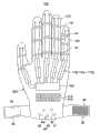
图23是表示变形例1的穿着式动作辅助装置10A的立体图。在此需要说明的是,在图23中,对于与上述图1相同的部分附上相同的符号并省略其说明。如图23所示,变形例1的穿着式动作辅助装置10A设置有动作辅助手套20A、多个线状部件500、驱动部510、生物信号检测部60、控制单元70A、充电式电池610。充电式电池610在其表面配置有太阳电池612,由接受室内的照明光或太阳光而进行发电的太阳电池612而时常被充电。FIG. 23 is a perspective view showing a wearable
动作辅助手套20A与上述实施例1的动作辅助手套20一样,以紧贴穿着者的手的方式被形成为配合手的大小的立体形状。Like the motor assist
另外,在动作辅助手套20A上,设置有穿着者插入手指的作为被驱动部的手指插入部21A。如图24A所示,手指插入部21A的尖端下侧,设置有检测物体X的物体检测传感器600。In addition, the
物体检测传感器600由薄的具有可挠性的薄膜开关(membrane switches)等构成,接触到物体X时向控制单元70A输出检测信号。控制单元70A被输入来自物体检测传感器600的检测信号时,进行产生驱动力的演算处理以使各手指插入部21A进行把持动作。The
另外,动作辅助手套20A的各手指插入部21A的尖端设置物体检测传感器600,还可以在手腕或手的侧面等的不与物体X接触的非把持部分配置按动(push)式的微动开关(micro switches),例如微动开关与桌子或椅子等接触而被操作开启时,通过控制来驱动线状部件500使各手指插入部21A进行把持动作。In addition, an
另外,作为物体检测传感器600,并不限定于上述薄膜开关、微动开关,也可以使用例如以非接触的方式检测物体X或放置物体X的桌子的反射型光传感器或靠近传感器(感应型靠近传感器、静电容量型靠近传感器、磁力型靠近传感器)。In addition, as the
在动作辅助手套20A的手背侧及各手指插入部21A的两侧沿各手指插入部21A的延伸方向配置有多个线状部件500。多个线状部件500的一端与动作辅助手套20A的各手指插入部21A连接。在此需要说明的是,在本变形例中,为了确保由线状部件500的动作所得到的辅助动力,可以在1根手指插入部21A上配置4条线状部件500,并根据穿着者手的情况适当增减线状部件500的条数。A plurality of
手指插入部21A与动作辅助手套20A作为一体被形成,被形成为覆盖各手指全体的帽状。另外,多个线状部件500通过被缠绕在手指关节上的环扎环32、34、36被环扎在动作辅助手套20A的外侧。因此,驱动部510能够借助各线状部件500将驱动力高效率地传递到动作辅助手套20A的各手指插入部21A。The
再有,多个线状部件500被缝合在动作辅助手套20A的外侧。因此,随着多个线状部件500沿伸展方向或弯曲方向动作,动作辅助手套20A的各手指插入部21A也同线状部件500作为一体沿伸展方向或弯曲方向动作。本变形例1的线状部件500由中空形状的树脂管(筒状体)构成,沿长度方向延伸形成内部填充有流动体520的中空路径502。另外,多个线状部件500虽然是传递驱动力的部件,但比起金属部件等被大幅轻量化,能够减轻穿着者的负担。In addition, a plurality of
如图24A及图24B所示,各手指插入部21A的关节部分的外侧设置有上述施力部件90。因此,动作辅助手套20A的覆盖手指关节的手指插入部21A的表面上,被赋予施力部件90的施加力,使得手指插入部21A趋向伸展,施加力作为各手指关节的伸展动作(从图24B所示把持状态到图2A所示开放状态的动作)的辅助力产生作用。As shown in FIGS. 24A and 24B , the above-mentioned urging
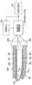
如图25A及图25B所示,驱动部510具有对线状部件500的中空路径502中填充的流动体(以梨皮斑点图案表示)进行加压或减压的致动器510a~510j。致动器510a~510j的扁平形状的外壳530的内部收纳有一对珀耳帖元件(Peltier device)540。珀耳帖元件540是由电流的流动方向发热而进行加热或由热吸收而进行冷却从而调节流动体520的温度的温度调节部件。As shown in FIGS. 25A and 25B , the driving
另外,流动体由具有高温下体积变小、低温下体积变大性质的凝胶(gel)构成。流动体520中所使用的凝胶由例如具有通过灌入向高分子的三维网状构造中灌入液体使其体积增大10倍的性质的被称为聚苄甲基丙烯酸酯(polybenzyl methacrylate)的高分子和咪唑(imidazolium)系的离子液体所形成。In addition, the fluid is composed of a gel (gel) that has a property of decreasing in volume at high temperature and increasing in volume at low temperature. The gel used in the
由于在一对珀耳帖元件540的缝隙间从上下方向同时加热或冷却,所以流动体520的体积能够在短时间内缩小或增大而填充到外壳530内。另外,当致动器510a~510j在其扁平形状的空间内被填充流动体520的状态下由一对珀耳帖元件540进行加热或冷却时,向与出口550连接的线状部件500的中空路径502对流动体520赋予响应体积变化的压力(减压或增压)。Since the gap between the pair of
由于中空路径502的内径被形成为比外壳530内空间小得多的尺寸,所以随着外壳530内的加热或冷却的流动体520的体积变化量能够在中空路径502中相对流动体520被增幅而加压或减压。另外,各线状部件500的内部由具有中空路径502的树脂制细管所形成,而且在树脂制细管的内侧及外侧,形成有如上述图3A所示的波纹管状(bellows状)的细微的凹凸形状。因此,各线状部件500被设置为能够根据填充在中空路径502中的流动体520的压力的增减而沿长度方向(轴方向)伸缩。Since the inner diameter of the
各线状部件500由环扎环32、34、36被环扎在动作辅助手套20A的外侧。动作辅助手套20A的手背侧被减压而各线状部件500沿长度方向缩短时,以及动作辅助手套20A的手的平侧被加压而各线状部件500沿长度方向伸长时,向各手指插入部21A赋予驱动力以使各手指插入部21A伸长。另外,动作辅助手套20A的手背侧被加压而各线状部件500沿长度方向伸长时,以及动作辅助手套20A的手的平侧被减压而各线状部件500沿长度方向缩短时,赋予驱动力以使各手指插入部21A部分弯曲。Each of the
在线状部件500中使用树脂材料,该树脂材料具有维持从低温到高温变化的流动体520被填充在密封的中空路径502的状态的耐热性。再有,充电式电池610中被充电的电力被供给到致动器510a~510j的各珀耳帖元件540。为了供给各珀耳帖元件540的消耗电力,充电式电池610由太阳电池612时常充电。The
在本变形例中,在各手指插入部21的侧面各配置有2条线状部件500,并且各手指插入部21上各自并排设置有致动器510a~510j。换言之,1根手指插入部21A的两侧配置有4条线状部件500,手掌侧和手背侧分别与不同的驱动部连接。因此,通过加压各线状部件500的手掌侧、加压各线状部件500的手背侧,能够驱动各手指插入部21A使其成为伸长的状态。相反,减压各线状部件500的手掌侧、加压手背侧,能够驱动各手指插入部21A使其成为把持状态。In this modified example, two
控制单元70A根据由生物信号检测部60的生物电位传感器61~65检测出的生物信号进行演算处理,并向致动器510a~510j输出驱动控制信号。由于控制单元70A中的控制处理与上述实施例1~6的控制部100及100A~F执行同样的控制处理,所以在此省略对其控制处理的说明。The
这样,使用变形例1的动作辅助手套20A时,由于与实施例1一样,由于能够通过根据来自控制单元70A的驱动控制信号将使线状部件500沿手指插入部21A的关节的动作方向伸展或弯曲,传递驱动部510的驱动力以使穿着者的手指的关节进行动作,因此能够实现轻量化,而且能够减轻穿着者的负担。In this way, when using the
另外,对流动体510进行温度调节的温度调节部件不限定于上述珀耳帖元件,也可以例如在中空路径502中配置电热丝进行通电加热。由此结构,由于能够对中空路径502内的流动体520进行全体加热所以能够使温度迅速变化,从而提高驱动部的应答性。关于流动体520的冷却,由于中空路径502形成为细线状,所以通过从中空路径502表面的散热能够充分快速地冷却。In addition, the temperature adjustment means for adjusting the temperature of the fluid 510 is not limited to the above-mentioned Peltier element, and for example, a heating wire may be arranged in the
另外,在流动体520中也可使用混入有纤维状导电体的凝胶(gel)。这种凝胶具有如下性质:通过对凝胶施加电压时,该纤维状导电体由于库伦力在凝胶内移动排列并形成导电路,使得随着在此导电路中电流流动而发热、凝胶内部温度变化从而引起凝胶自身的体积变化。使用这种混入有纤维状导电体的凝胶时,可以在配置一对珀耳帖元件540的位置上代替珀耳帖元件配置施加电压用的电极,对此电极间的凝胶施加电场并驱动驱动部510。In addition, gel mixed with fibrous conductors may also be used for the
(变形例2)(Modification 2)
图26是表示变形例2的穿着式动作辅助装置10B的立体图。在此需要说明的是,在图26中,对于与上述图23相同的部分附上相同的符号并省略其说明。如图26所示,穿着式动作辅助装置10B将动作辅助手套20B、上述变形例1的多个线状部件500、驱动部510、生物信号检测部60及控制单元70A收容在外侧动作辅助手套与内侧动作辅助手套之间。因此,驱动部510能够借助各线状部件500将驱动力高效地传递到动作辅助手套20B的各手指插入部21B。FIG. 26 is a perspective view showing a wearable
由于充电式电池610在其表面配置有太阳电池612,太阳电池612被设置为从动作辅助手套20B的外侧手套露出。Since the
如图27A及图27B所示,由于动作辅助手套20B在外观上,多个线状部件500、驱动部510、生物信号检测部60及控制单元70A被隐藏不能被看见,所以能够向通常的手套一样进行设计。由此,穿着者即便是穿着着动作辅助手套20B外出时也能够不介意他人的目光而进行手指关节的动作。As shown in Fig. 27A and Fig. 27B, since the
另外,在上述动作辅助手套20B中,在外侧动作辅助手套的内侧配置多个线状部件500、驱动部510、生物信号检测部60及控制单元70A,可以在多个线状部件500、驱动部510、生物信号检测部60及控制单元70A的至少由手指插入所接触的部分上,部分缝合布制、皮革制或合成皮革的覆盖部件。In addition, in the above-mentioned
这样,在使用变形例2的动作辅助手套20B时,也与实施例一样,由于能够通过根据来自控制单元70A的驱动控制信号将使线状部件500沿手指插入部21B的关节的动作方向伸展或弯曲,传递驱动部510的驱动力以使穿着者的手指的关节进行动作,因此能够实现轻量化,而且能够减轻穿着者的负担。In this way, when using the
(变形例3)(Modification 3)
图28是表示变形例3的穿着式动作辅助装置10C的立体图。在此需要说明的是,在图28中,对于与上述图23相同的部分附上相同的符号并省略其说明。如图28所示,穿着式动作辅助装置10C设置有动作辅助手套20C、多个线状部件700、驱动部710、生物信号检测部60、控制单元70C及充电式电池610。FIG. 28 is a perspective view showing a wearable
多个线性部件700为例如钢琴丝(piano wire)等的线材。驱动部具有线性马达(linear motor)710a~710j。多个线状部件700是传递驱动力的部件,但比起棒状的金属部件等,其能够被大幅轻量化并减轻穿着者的负担。The plurality of
线性马达710a~710j的可动元件(磁铁)上连接有线状部件700的一端。另外,线状部件700的另一端与动作辅助手套20C的手指插入部21C连接。另外,动作辅助手套20C上设置有测量线性马达710a~710j的可动元件的移动量的线性刻度(linear scale)。作为线性刻度的安装位置,可以设置为可测量可动元件的移动量,或者也可以沿着可动元件连接的线状部件700设置。One end of the
再有,多个线状部件700被缝合在动作辅助手套20C的外侧。因此,随着多个线状部件700沿伸展方向或弯曲方向进行动作,动作辅助手套20C的各手指插入部21C也与线状部件700作为一体沿伸展方向或弯曲方向进行动作。由此,驱动部710能够借助各线状部件700将线性马达710a~710j的驱动力高效地传递到动作辅助手套20C的各手指插入部21C。In addition, a plurality of
线性马达710a~710j根据来自控制单元70C的控制信号对构成固定元件的多个线圈进行通电并励磁,并产生对可动元件的推力。如图29A及29B所示,沿着动作辅助手套20C的各手指插入部21C延伸设置的多个线性部件700,由于线性马达710a~710j的推力被沿伸展方向或弯曲方向直接驱动。The
本变形例3的控制单元70C,与上述各实施例一样,根据由生物信号检测部60的生物电位传感器61~65检测出的生物信号进行演算处理(稍后详述),并向致动器710a~710j输出驱动控制信号。由于控制单元70C中的控制处理与上述实施例1~6的控制部100及100A~F执行同样的控制处理,所以在此省略对其控制处理的说明。The
这样,使用变形例3的动作辅助手套20C时,由于与实施例1一样,由于能够通过根据来自控制单元70C的驱动控制信号将使线状部件700沿手指关节的动作方向伸展或弯曲,传递驱动部510的驱动力以使穿着者的手指的关节进行动作,因此能够实现轻量化,而且能够减轻穿着者的负担。In this way, when using the
(变形例4)(Modification 4)
图30是表示变形例4的穿着式动作辅助装置10D的立体图。如图30所示,穿着式动作辅助装置10d设置有动作辅助手套20D、多个线状部件800、施加电压切换电路810、生物信号检测部60、控制单元70D及充电式电池610。FIG. 30 is a perspective view showing a wearable
各线状部件800由环扎环32、34及36被环扎在各手指插入部21D上。由此,通过线状部件800产生的驱动力被直接传递到各手指插入部21D,并产生驱动各手指插入部21D使其变成直线状态(伸直各手指的状态)或弯曲状态(弯曲各手指的状态)的作用。Each of the
多个线状部件800例如由根据施加电压的大小或施加电压的正负所产生的体积变化而产生驱动力的具有可挠性的合成树脂基板构成。换言之,各线状部件800响应由施加电压切换电路810施加在电极层的电压,产生驱动各手指插入部21D从直线状态到弯曲状态的驱动力或从弯曲状态到直线状态的驱动力。The plurality of
另外,由于各线状部件800其自身就是产生驱动力的驱动部件,因此不需要由其他马达等构成的致动器,所以比起需要设置有另一个致动器的装置能够大幅轻量化并且减轻穿着着的负担。In addition, since each
在此需要说明的是,在本变形例4的图29中,虽然示例出了在各手指插入部21D的里侧(手背侧)各配置有2条线状部件800的结构的例子,但不限定于此,也可以为配置3条以上线状部件800的结构。It should be noted here that in FIG. 29 of Modification 4, although an example in which two
图31A是表示对变形例4的穿着式动作辅助装置10D的手指插入部的一部分剖视的图。图31B是表示变形例4的穿着式动作辅助装置10D的手指插入部被弯曲时的动作状态的图。31A is a diagram showing a partial sectional view of a finger insertion portion of a wearable
如图31所示,在动作辅助手套20D的各手指插入部21D的表面侧(手掌侧)和里侧(手背侧)以沿各手指插入部21D的手指延伸方向延伸设置的方式安装有线状部件800。As shown in FIG. 31 , on the surface side (palm side) and the back side (hand side) of each
各线状部件800的电极层801、802分别借助电压控制用电线804与施加电压切换电路810(810a~810J)的输出端子连接。施加电压切换电路810分别与作为电压供给源的充电式电源610连接,并且根据来自控制单元70D的控制信号对在各线状部件800的电极层801、802上施加的电压的极性及大小进行控制。The electrode layers 801 and 802 of each
线状部件800层压成在平行配置的一对电极层801、802之间介入有驱动层803。作为驱动层803,例如由根据施加电压的极性(正负)驱动力方向发生切换的离子交换树脂形成。在这种离子交换树脂的上下面压层形成电极层801、802的离子传导致动器上未施加电压的状态下,处于延伸成直线状的静止状态(非驱动状态)。另外,在离子交换树脂的内部,通过对一对电极层801、802的正负进行切换而使高分子电解质内的正侧(阳极侧)的阳离子向负侧(阴极侧)移动,使得由离子交换树脂的正负产生润胀(swelling)上的差而向负侧(阴极侧)反转变形。驱动层803通过表里侧的润胀的差而产生的力产生驱动力使各手指插入部21D进行动作。The
由此,通过施加电压切换电路810将一对电极层801、802的极性切换成正或负,从而能够切换驱动层803的变形方向,并能够通过施加电压的大小对变形量进行控制。Thus, by switching the polarity of the pair of
在此,对各线状部件800的驱动力的产生动作进行说明。Here, the driving force generating operation of each
例如,当以将各线状部件800的电极层801、802中上侧的电极层801设为负(阴极)、下侧的电极层802设为正(阳极)的方式将施加电压的极性通过施加电压切换电路810进行切换时,在驱动层803上,由于上侧的润胀比下侧的变得更大,印次产生将各手指插入部21D向向方弯曲的驱动力Fa。For example, among the electrode layers 801, 802 of each
如图31B所示,各手指插入部21D被沿弯曲方向驱动,如虚线所示从直线状态XA向弯曲各手指关节的弯曲状态XB动作。另外,当将向各线状部件800的电极层801、802的电压设置为停止(零)时,各手指插入部21D被沿伸展方向驱动,如实线所示从弯曲状态XB向直线状态XA以缓慢的速度复原。As shown in FIG. 31B , each
再有,在弯曲状态XB中,当以将各线状部件800的电极层801、802中上侧的电极层801设为正(阳极)、下侧的电极层802设为负(阴极)的方式将施加电压的极性通过施加电压切换电路810进行切换时,产生将要使各手指插入部21D向上方反转的驱动力Fb。这样,通过对施加在各线状部件800的电极层801、802上的电压的极性进行切换,从而能够使各手指插入部21D如实线所示从弯曲状态XB向直线状态XA迅速地复原。此复原动作速度对在进行康复(rehabilitation)时非常有效,而且能够给予手指从弯曲手指的状态向伸出方向的足够大的转矩。Furthermore, in the bent state XB, when the
这样,使用变形例4的动作辅助手套20D时,与实施例1一样,通过根据来自控制单元70D的驱动控制信号,将施加在各线状部件800的电极层801、802的电压的极性进行切换,从而能够产生向使各手指插入部21D向伸展或弯曲的方向的驱动力Fa、Fb,因此能够实现轻量化,而且能够减轻穿着者的负担。In this way, when using the
另外,作为上述驱动层803,不限定于离子变换树脂,当然还可以使用通过施加电压产生由于体积膨胀的变形或位移的压电聚合物、导电性聚合物或电致伸缩聚合物等高分子材料。In addition, as the above-mentioned
产业上的可利用性如下:The industrial availability is as follows:
上述实施例尽管是对通过穿着动作辅助手套20而对穿着者的各手指关节进行辅助的情况进行说明,当并不限定于此,本发明由于通过使用上述动作辅助手套20还能进行手指关节动作的康复训练(机能恢复训练),因此还可以作为康复用手套来使用。Although the above-mentioned embodiment has described the situation in which the wearer's finger joints are assisted by wearing the
上述变形例1~4中,也可以将动作辅助手套20A~20D的指尖部分与实施例1的动作辅助手套20一样剪掉后使穿着者的指尖露出。In
本发明并不限定于具体记载的实施例,在权利要求书中记载的本发明的要点的范围内,可进行多种的变形或改良。The present invention is not limited to the specifically described examples, and various modifications and improvements can be made within the scope of the gist of the present invention described in the claims.
本国际申请以2009年4月9日申请的日本专利申请2009-094695号作为主张优先权的基础,本国际申请在此援引该日本专利申请的全部内容。This international application is based on the Japanese patent application No. 2009-094695 filed on April 9, 2009 as the basis for claiming priority, and the entire content of the Japanese patent application is hereby cited in this international application.
Claims (20)
Priority Applications (2)
| Application Number | Priority Date | Filing Date | Title |
|---|---|---|---|
| CN201410415255.4ACN104188740B (en) | 2009-04-09 | 2010-04-09 | Wearable action assisting device |
| CN201410415108.7ACN104188739B (en) | 2009-04-09 | 2010-04-09 | Wearable motion assist device |
Applications Claiming Priority (3)
| Application Number | Priority Date | Filing Date | Title |
|---|---|---|---|
| JP2009094695AJP5472680B2 (en) | 2009-04-09 | 2009-04-09 | Wearable motion assist device |
| JP2009-094695 | 2009-04-09 | ||
| PCT/JP2010/056470WO2010117065A1 (en) | 2009-04-09 | 2010-04-09 | Wearable motion assist device |
Related Child Applications (2)
| Application Number | Title | Priority Date | Filing Date |
|---|---|---|---|
| CN201410415255.4ADivisionCN104188740B (en) | 2009-04-09 | 2010-04-09 | Wearable action assisting device |
| CN201410415108.7ADivisionCN104188739B (en) | 2009-04-09 | 2010-04-09 | Wearable motion assist device |
Publications (2)
| Publication Number | Publication Date |
|---|---|
| CN102387760Atrue CN102387760A (en) | 2012-03-21 |
| CN102387760B CN102387760B (en) | 2015-06-10 |
Family
ID=42936347
Family Applications (3)
| Application Number | Title | Priority Date | Filing Date |
|---|---|---|---|
| CN201080016060.2AExpired - Fee RelatedCN102387760B (en) | 2009-04-09 | 2010-04-09 | Wearable motion assistance device |
| CN201410415108.7AExpired - Fee RelatedCN104188739B (en) | 2009-04-09 | 2010-04-09 | Wearable motion assist device |
| CN201410415255.4AExpired - Fee RelatedCN104188740B (en) | 2009-04-09 | 2010-04-09 | Wearable action assisting device |
Family Applications After (2)
| Application Number | Title | Priority Date | Filing Date |
|---|---|---|---|
| CN201410415108.7AExpired - Fee RelatedCN104188739B (en) | 2009-04-09 | 2010-04-09 | Wearable motion assist device |
| CN201410415255.4AExpired - Fee RelatedCN104188740B (en) | 2009-04-09 | 2010-04-09 | Wearable action assisting device |
Country Status (7)
| Country | Link |
|---|---|
| US (1) | US8998831B2 (en) |
| EP (1) | EP2417941B1 (en) |
| JP (1) | JP5472680B2 (en) |
| KR (1) | KR101361999B1 (en) |
| CN (3) | CN102387760B (en) |
| PL (1) | PL2417941T3 (en) |
| WO (1) | WO2010117065A1 (en) |
Cited By (23)
| Publication number | Priority date | Publication date | Assignee | Title |
|---|---|---|---|---|
| CN103285570A (en)* | 2013-06-13 | 2013-09-11 | 潘林 | Basketball shooting training device and wearing method thereof |
| CN104622613A (en)* | 2015-03-17 | 2015-05-20 | 汪兴欣 | Multifunctional hand/foot sleeve |
| CN104826280A (en)* | 2014-02-07 | 2015-08-12 | 松下知识产权经营株式会社 | Muscle supporter and muscle support method |
| CN104921902A (en)* | 2014-03-17 | 2015-09-23 | 香港理工大学 | A rehabilitation system combining sensory function and mechanical assistance |
| CN106214418A (en)* | 2016-07-01 | 2016-12-14 | 山东大学 | A kind of flexible wearable ectoskeleton drive lacking is all referring to training rehabilitation mechanical hand |
| CN106393095A (en)* | 2015-06-15 | 2017-02-15 | 通用汽车环球科技运作有限责任公司 | Grip assist device with automatic mode control logic |
| CN106456435A (en)* | 2014-06-12 | 2017-02-22 | 新加坡国立大学 | Actuator device, method and system for limb rehabilitation |
| CN106618948A (en)* | 2016-11-09 | 2017-05-10 | 矽魅信息科技(上海)有限公司 | Intelligent power assisting rehabilitation gloves |
| CN106794106A (en)* | 2014-10-07 | 2017-05-31 | 山本圭治郎 | Articulation assist device |
| CN107684504A (en)* | 2017-11-20 | 2018-02-13 | 傅雪梅 | A kind of rehabilitation training gloves |
| CN108444436A (en)* | 2018-02-28 | 2018-08-24 | 西安交通大学 | A kind of hand gestures measuring system and method based on flexible large deformation sensor |
| CN108743215A (en)* | 2018-04-11 | 2018-11-06 | 刘春龙 | A kind of rehabilitation training system based on flexible restoring gloves |
| CN109310509A (en)* | 2016-05-30 | 2019-02-05 | 拜奥伺服技术股份公司 | Grip Enhancement Support |
| CN109674483A (en)* | 2018-12-24 | 2019-04-26 | 上海大学 | A kind of adjustable single finger is at the uniform velocity passive exercise device with and single finger Muscle tensility detection method |
| CN110151495A (en)* | 2019-06-27 | 2019-08-23 | 深圳睿瀚医疗科技有限公司 | Roller hand device for healing and training |
| CN110269776A (en)* | 2019-06-28 | 2019-09-24 | 清华大学深圳研究生院 | A kind of finger recovering aid fingerstall and its manufacturing method based on pneumatic software actuator |
| CN110613580A (en)* | 2019-02-28 | 2019-12-27 | 复旦大学 | Finger-to-finger rehabilitation training glove and method |
| CN111297630A (en)* | 2020-02-27 | 2020-06-19 | 吉林大学 | A portable hand hemiplegia rehabilitation exercise auxiliary device |
| CN111307464A (en)* | 2018-12-11 | 2020-06-19 | 劳斯莱斯有限公司 | Inspection system |
| CN112245221A (en)* | 2020-10-14 | 2021-01-22 | 北京邮电大学 | A Novel Hand Exoskeleton Rehabilitation Device |
| TWI718762B (en)* | 2019-11-15 | 2021-02-11 | 國立雲林科技大學 | Smart wearable system and operation method thereof |
| CN116172859A (en)* | 2023-03-03 | 2023-05-30 | 大连理工大学 | A multi-point sensing glove for massage assistance and its use method |
| CN117138310A (en)* | 2023-08-11 | 2023-12-01 | 华南理工大学 | A VR rehabilitation training glove |
Families Citing this family (152)
| Publication number | Priority date | Publication date | Assignee | Title |
|---|---|---|---|---|
| US20150088043A1 (en)* | 2009-07-15 | 2015-03-26 | President And Fellows Of Harvard College | Actively controlled wearable orthotic devices and active modular elastomer sleeve for wearable orthotic devices |
| KR101727594B1 (en)* | 2010-12-21 | 2017-04-17 | 삼성전자주식회사 | Apparatus for transmitting force vector |
| CN103442667B (en)* | 2011-03-16 | 2015-08-19 | 达医雅工业股份有限公司 | Glove-type power assist device |
| WO2012165880A2 (en)* | 2011-05-31 | 2012-12-06 | 주식회사 네오펙트 | Apparatus for rehabilitation exercise, method and device for controlling proactive assistance control in apparatus for rehabilitation exercise, and mobile-linked glove apparatus for inputting data |
| KR101457201B1 (en)* | 2011-05-31 | 2014-10-31 | 주식회사 네오펙트 | Rehabilitation Exercise Device For Neuropathy Patient |
| JP2013146328A (en)* | 2012-01-18 | 2013-08-01 | Seiko Epson Corp | Device for supporting operation |
| US9067325B2 (en)* | 2012-02-29 | 2015-06-30 | GM Global Technology Operations LLC | Human grasp assist device soft goods |
| WO2013168738A1 (en) | 2012-05-09 | 2013-11-14 | 学校法人産業医科大学 | Exercise training apparatus |
| US9326909B2 (en)* | 2012-05-11 | 2016-05-03 | University Of Tennessee Research Foundation | Portable hand rehabilitation device |
| JP6016453B2 (en)* | 2012-05-21 | 2016-10-26 | 国立大学法人九州大学 | Hand Exo Skeleton Device with Three-layer Linked Spring Slide Mechanism |
| US9891718B2 (en)* | 2015-04-22 | 2018-02-13 | Medibotics Llc | Devices for measuring finger motion and recognizing hand gestures |
| US10921886B2 (en)* | 2012-06-14 | 2021-02-16 | Medibotics Llc | Circumferential array of electromyographic (EMG) sensors |
| JP5882145B2 (en)* | 2012-06-22 | 2016-03-09 | 独立行政法人国立高等専門学校機構 | Electric prosthesis |
| EP2911578B1 (en) | 2012-10-24 | 2019-12-25 | Dreamscape Medical LLC | Systems for detecting brain-based bio-signals |
| US9387112B2 (en) | 2013-02-28 | 2016-07-12 | Marvin Frank Bryant | Myoelectric hand orthosis |
| KR102059346B1 (en) | 2013-03-05 | 2020-02-11 | 삼성전자주식회사 | Emg sensor system, and method of operation of emg sensor system |
| EP2954988B1 (en)* | 2013-03-08 | 2020-05-06 | Kyushu University, National University Corporation | Hand exoskeleton device |
| JP2014184027A (en)* | 2013-03-25 | 2014-10-02 | Seiko Epson Corp | Finger assist device |
| CN104107133A (en)* | 2013-04-21 | 2014-10-22 | 崔贵富 | Magic glove |
| US20140364771A1 (en)* | 2013-05-16 | 2014-12-11 | David A. Pitts | Pressure sensitive assemblies for limiting movements adverse to health or surgical recovery |
| WO2014186546A2 (en)* | 2013-05-17 | 2014-11-20 | Massachusetts Institute Of Technology | Apparatus and method for augmenting functionality of a human hand using supernumerary artificial appendages |
| JP6210364B2 (en)* | 2013-05-24 | 2017-10-11 | 株式会社安川電機 | Training equipment |
| JP6210363B2 (en)* | 2013-05-24 | 2017-10-11 | 株式会社安川電機 | Training equipment |
| KR101484402B1 (en)* | 2013-08-08 | 2015-01-19 | 한국과학기술원 | Finger force assistance device with partially open structure |
| US10349888B2 (en) | 2013-10-08 | 2019-07-16 | Carlos Federico Muniz | Wearable electroencephalography device and methods of use thereof |
| KR101515951B1 (en)* | 2013-12-02 | 2015-05-04 | 주식회사 피앤에스미캐닉스 | Apparatus for exercising of finger |
| EP3099275B1 (en) | 2014-01-31 | 2021-10-13 | Nuada, Lda | Joint assistive and locking device |
| KR101500483B1 (en) | 2014-04-17 | 2015-03-19 | (주)노아텍 | Rehabilitation System And Method For Finger |
| KR101628311B1 (en)* | 2014-04-21 | 2016-06-08 | 한국기술교육대학교 산학협력단 | Exoskeleton-Type Glove |
| KR101526947B1 (en)* | 2014-04-21 | 2015-06-11 | 한국기술교육대학교 산학협력단 | Exoskeleton-Type Glove |
| US9468847B2 (en)* | 2014-04-30 | 2016-10-18 | Umm Al-Qura University | Tactile feedback gloves |
| KR101609158B1 (en)* | 2014-05-12 | 2016-05-17 | 울산과학기술원 | A finger motion measurement system and measurement method of finger motion |
| CN105267007B (en)* | 2014-05-29 | 2019-03-08 | 精工爱普生株式会社 | Driving device and driving method thereof |
| JP2015223418A (en)* | 2014-05-29 | 2015-12-14 | セイコーエプソン株式会社 | Driving device and driving method thereof |
| US10540597B1 (en) | 2014-06-25 | 2020-01-21 | Bosch Sensortec Gmbh | Method and apparatus for recognition of sensor data patterns |
| KR102238722B1 (en) | 2014-06-30 | 2021-04-22 | 주식회사 네오펙트 | Wearing Unit For Finger Movement Measuring Apparatus |
| KR102081981B1 (en) | 2014-06-30 | 2020-02-26 | 주식회사 네오펙트 | Finger Movement Measuring Apparatus |
| US10478370B2 (en)* | 2014-06-30 | 2019-11-19 | Rehabilitation Institute Of Chicago | Actuated glove orthosis and related methods |
| FR3024030B1 (en)* | 2014-07-25 | 2016-08-26 | Commissariat Energie Atomique | DEVICE FOR ASSISTING HAND PRINTING OF THE HAND |
| KR102257902B1 (en)* | 2014-07-29 | 2021-05-28 | 삼성전자주식회사 | Battery pack prividing different kind power source and charging method thereof |
| KR102250265B1 (en) | 2014-09-01 | 2021-05-10 | 삼성전자주식회사 | Apparatus and method for adjusting torque pattern |
| CN105411810A (en) | 2014-09-12 | 2016-03-23 | 精工爱普生株式会社 | Driving apparatus and driving method therefor |
| KR102342072B1 (en)* | 2014-10-14 | 2021-12-22 | 삼성전자주식회사 | Method and apparatus for conrolling walking assist |
| JP2016083000A (en)* | 2014-10-23 | 2016-05-19 | セイコーエプソン株式会社 | Drive unit, finger joint driving device, and driving method |
| TWI549666B (en)* | 2015-01-05 | 2016-09-21 | 國立清華大學 | Rehabilitation system with stiffness measurement |
| US10912701B2 (en)* | 2015-01-07 | 2021-02-09 | The Board Of Regents Of The University Of Texas System | Fluid-driven actuators and related methods |
| CN104545907A (en)* | 2015-01-19 | 2015-04-29 | 广州一康医疗设备实业有限公司 | Portable hand function training device |
| KR101541082B1 (en)* | 2015-01-23 | 2015-08-03 | 주식회사 네오펙트 | System and method for rehabilitation exercise of the hands |
| JP6489422B2 (en)* | 2015-01-28 | 2019-03-27 | パナソニックIpマネジメント株式会社 | Assist wear, assist wear operating method, and control program |
| KR101682951B1 (en)* | 2015-02-11 | 2016-12-20 | 울산과학기술원 | A finger motion measurement system and measurement method of finger motion |
| SE1550281A1 (en)* | 2015-03-06 | 2016-09-07 | Fingerprint Cards Ab | Method and system for estimating finger movement |
| US10786022B2 (en)* | 2015-04-29 | 2020-09-29 | Bioservo Technologies Aktiebolag | Control system for a strengthening glove |
| EP3106133B1 (en) | 2015-06-19 | 2018-01-31 | Georg-August-Universität Göttingen Stiftung Öffentlichen Rechts Universitätsmedizin | Powered, multi-functional limb movement auxiliary device, particularly prosthesis and movement-assisting orthosis, with combined estimation regimes |
| US20170000369A1 (en)* | 2015-07-03 | 2017-01-05 | Elwha Llc | Electrocardiogram systems and related methods |
| TWI623006B (en) | 2015-07-14 | 2018-05-01 | 宏碁股份有限公司 | Wearable trigger |
| US10121066B1 (en)* | 2017-11-16 | 2018-11-06 | Blast Motion Inc. | Method of determining joint stress from sensor data |
| KR101701695B1 (en)* | 2015-08-07 | 2017-02-03 | 대한민국 | A wearable hand exoskeleton system |
| US10067564B2 (en) | 2015-08-11 | 2018-09-04 | Disney Enterprises, Inc. | Identifying hand gestures based on muscle movement in the arm |
| US20190060099A1 (en)* | 2015-10-09 | 2019-02-28 | The Trustees Of Columbia University In The City Of New York | Wearable and functional hand orthotic |
| ITUB20155515A1 (en)* | 2015-11-12 | 2017-05-12 | Idrogenet Srl | Support device for positioning and fixing of flexural sensors, applicable to a robotic mobilizer for hand rehabilitation |
| US10979673B2 (en)* | 2015-11-16 | 2021-04-13 | Deep North, Inc. | Inventory management and monitoring |
| CN108472192B (en)* | 2015-12-21 | 2020-09-22 | 山本圭治郎 | Joint movement assistance system |
| CN105496728B (en)* | 2016-01-12 | 2018-08-31 | 上海交通大学 | Soft robot gloves for hand movement function rehabilitation |
| KR101915238B1 (en)* | 2016-03-11 | 2018-11-05 | 한국생산기술연구원 | Rehabilitation device for hand and virtual reality rehabilitation training system comprising the same |
| KR101831602B1 (en) | 2016-03-15 | 2018-02-23 | 서울대학교산학협력단 | Upper limb rehabilitation robot module and upper limb rehabilitation robot system for precision control by image processing |
| CN105641877B (en)* | 2016-03-28 | 2018-05-25 | 南通优元美术图案设计有限公司 | A kind of tendon tempers brace |
| SE539819C2 (en)* | 2016-05-30 | 2017-12-12 | Bioservo Tech Aktiebolag | Finger glove liner and strengthening finger glove with liner |
| JP6742196B2 (en)* | 2016-08-24 | 2020-08-19 | Cyberdyne株式会社 | Life activity detection device and life activity detection system |
| US11672721B2 (en) | 2016-09-26 | 2023-06-13 | Cyberdyne, Inc. | Motion assisting apparatus |
| JP6832530B2 (en)* | 2016-09-30 | 2021-02-24 | パナソニックIpマネジメント株式会社 | Assist system, assist method and computer program |
| IT201600104668A1 (en)* | 2016-10-18 | 2018-04-18 | Univ Degli Studi Padova | Robotic system for the rehabilitation of the hand and relative method of control of a robot |
| US11036295B2 (en) | 2016-11-23 | 2021-06-15 | Microsoft Technology Licensing, Llc | Electrostatic slide clutch |
| CN107049325B (en)* | 2016-11-23 | 2023-09-05 | 上海健康医学院 | Novel wearable hand exoskeleton force-displacement real-time detection system and detection method |
| DE102016123153A1 (en)* | 2016-11-30 | 2018-05-30 | Helmut-Schmidt-Universität Universität der Bundeswehr Hamburg | DEVICE AND METHOD FOR MUSCLE POWER SUPPORT |
| EP3548994B1 (en)* | 2016-12-02 | 2021-08-11 | Pison Technology, Inc. | Detecting and using body tissue electrical signals |
| KR101885504B1 (en)* | 2016-12-27 | 2018-08-06 | 부산대학교 산학협력단 | Wearable glove system |
| KR101958949B1 (en)* | 2017-02-14 | 2019-03-15 | (주)이노컴퍼스 | Tube type interface apparatus for rehabilitation training |
| US11000082B2 (en)* | 2017-02-22 | 2021-05-11 | Purdue Research Foundation | Assistive glove for artificial hands |
| WO2018169111A1 (en)* | 2017-03-17 | 2018-09-20 | 한국생산기술연구원 | Hand rehabilitation device and virtual reality rehabilitation training system including same |
| CN106943277A (en)* | 2017-04-18 | 2017-07-14 | 上海理工大学 | The submissive exoskeleton rehabilitation manipulator of self adaptation Wearable |
| CN106983634A (en)* | 2017-04-20 | 2017-07-28 | 西安交通大学 | A kind of exoskeleton finger functional rehabilitation device based on multistage continuous structure |
| KR101914136B1 (en) | 2017-05-29 | 2018-11-02 | 한국생산기술연구원 | Rehabilitation device for hand |
| US11027436B2 (en)* | 2017-06-19 | 2021-06-08 | Alekh Rajesh BERI | Soft robotic assistive gripping device |
| SE542072C2 (en)* | 2017-06-19 | 2020-02-18 | Tendo Ab | A device for pivoting a body member around a joint |
| CN107080310A (en)* | 2017-06-22 | 2017-08-22 | 东北大学 | A kind of portable wearing power-assisted gloves |
| CN107184365B (en)* | 2017-07-07 | 2019-04-05 | 北京恒通信佳科技发展有限公司 | A kind of finger joint recovery movement auxiliary member |
| CN107184366B (en)* | 2017-07-07 | 2018-04-17 | 北京恒通信佳科技发展有限公司 | A kind of finger joint recovery device |
| JP6996908B2 (en)* | 2017-08-28 | 2022-01-17 | アイコクアルファ株式会社 | Suspended support of cargo carrier |
| JP6789903B2 (en)* | 2017-09-13 | 2020-11-25 | 株式会社東芝 | Myoelectric potential measuring device |
| CN107485538B (en)* | 2017-09-15 | 2023-08-11 | 肖飞 | A hand function rehabilitation training device for hemiplegic patients |
| JP6959441B2 (en)* | 2017-09-25 | 2021-11-02 | ネオフェクト シーオー., エルティーディー.NEOFECT Co., LTD. | Finger movement assist device |
| EP3479810B1 (en)* | 2017-09-25 | 2022-05-04 | NEOFECT Co., Ltd. | Device for assisting finger movement |
| KR102070138B1 (en)* | 2017-11-23 | 2020-01-28 | 주식회사 네오펙트 | Wearable type hand robot |
| EP3492933B1 (en)* | 2017-11-29 | 2024-09-18 | Nokia Technologies Oy | An apparatus for sensing comprising a flexible substrate |
| CN108073285B (en)* | 2018-01-02 | 2021-05-18 | 联想(北京)有限公司 | Electronic equipment and control method |
| TWI642421B (en)* | 2018-01-05 | 2018-12-01 | 富伯生醫科技股份有限公司 | Finger motion sensing gloves capable of fixing sensors |
| EP3518075B1 (en)* | 2018-01-24 | 2023-10-11 | C.R.F. Società Consortile per Azioni | Sensorized glove and corresponding method for ergonomic analysis of the hand, in particular a worker's hand |
| WO2019187030A1 (en)* | 2018-03-30 | 2019-10-03 | 圭治郎 山本 | Joint movement assistance device |
| CN108452500B (en)* | 2018-04-27 | 2023-07-07 | 成都工业学院 | a booster |
| US11023047B2 (en) | 2018-05-01 | 2021-06-01 | Microsoft Technology Licensing, Llc | Electrostatic slide clutch with bidirectional drive circuit |
| KR102058848B1 (en)* | 2018-05-02 | 2019-12-24 | 인제대학교 산학협력단 | Grip strength generating apparatus for cervical segments of the cord patient |
| SE544058C2 (en)* | 2018-05-25 | 2021-11-23 | Bioservo Tech Aktiebolag | Method and system for measuring ergonomic load, using a wearable force-assisting equipment |
| US10613626B2 (en)* | 2018-06-15 | 2020-04-07 | Immersion Corporation | Kinesthetically enabled glove |
| KR102071682B1 (en)* | 2018-07-02 | 2020-01-30 | 한국과학기술원 | Finger motion assist apparatus |
| CN109172265B (en)* | 2018-08-31 | 2022-02-25 | 京东方科技集团股份有限公司 | Finger exoskeleton robot |
| US10852825B2 (en)* | 2018-09-06 | 2020-12-01 | Microsoft Technology Licensing, Llc | Selective restriction of skeletal joint motion |
| DE102018122299A1 (en)* | 2018-09-12 | 2020-03-12 | Sportec Performance UG (haftungsbeschränkt) | Garment for sport and health-oriented posture support |
| CA3116012A1 (en)* | 2018-10-22 | 2020-04-30 | Abilitech Medical, Inc. | Hand assist orthotic |
| TWI691326B (en)* | 2018-10-24 | 2020-04-21 | 南臺學校財團法人南臺科技大學 | Lower support type rehabilitation device for fingers |
| USD918198S1 (en)* | 2018-10-25 | 2021-05-04 | Bebop Sensors, Inc. | Glove |
| US20200238022A1 (en)* | 2018-11-02 | 2020-07-30 | Ara Gulesserian | Apparatus for stimulating patient tissue or gum injection during medical procedure injections |
| SE1851567A1 (en)* | 2018-12-12 | 2020-06-13 | Tendo Ab | Control of an active orthotic device |
| US10890970B2 (en)* | 2018-12-24 | 2021-01-12 | Lasarrus Clinic And Research Center | Flex force smart glove for measuring sensorimotor stimulation |
| CN109514544A (en)* | 2018-12-27 | 2019-03-26 | 浙江工业大学 | A kind of bionic mechanical hand |
| US10449677B1 (en)* | 2019-03-12 | 2019-10-22 | United Arab Emirates University | Robotic gripping assist |
| CN110236874B (en)* | 2019-04-30 | 2021-07-02 | 南通大学附属医院 | A kind of hand recovery training device for hand surgical medical care |
| US10860102B2 (en) | 2019-05-08 | 2020-12-08 | Microsoft Technology Licensing, Llc | Guide for supporting flexible articulating structure |
| US11054905B2 (en)* | 2019-05-24 | 2021-07-06 | Microsoft Technology Licensing, Llc | Motion-restricting apparatus with common base electrode |
| US11061476B2 (en) | 2019-05-24 | 2021-07-13 | Microsoft Technology Licensing, Llc | Haptic feedback apparatus |
| EP3979966A4 (en) | 2019-06-07 | 2023-07-05 | Osind Medi Tech Private Limited | SELF-PROPELLED REHABILITATION DEVICE AND METHOD THEREOF |
| US20220253140A1 (en)* | 2019-07-03 | 2022-08-11 | Brink Bionics Inc. | Myoelectric wearable system for finger movement recognition |
| KR102331549B1 (en)* | 2019-10-07 | 2021-11-26 | 주식회사 네오펙트 | Glove for assisting finger movement |
| WO2021071195A1 (en)* | 2019-10-07 | 2021-04-15 | 주식회사 네오펙트 | Rehabilitation glove |
| CN113260340A (en) | 2019-10-11 | 2021-08-13 | 神经解决方案股份有限公司 | Orthopedic system and rehabilitation of injured body parts |
| USD942023S1 (en)* | 2019-10-21 | 2022-01-25 | Neofect Co., Ltd. | Hand rehabilitation training apparatus |
| KR102275881B1 (en)* | 2019-10-25 | 2021-07-12 | 서울대학교산학협력단 | Upper Extremity Rehabilitation Apparatus for Wearable |
| KR102238692B1 (en) | 2020-02-20 | 2021-04-22 | 주식회사 네오펙트 | Finger Movement Measuring Apparatus |
| CN111643315B (en)* | 2020-04-27 | 2021-09-03 | 东南大学 | Flexible hand function rehabilitation device based on rope drive |
| KR102470787B1 (en)* | 2020-06-26 | 2022-11-28 | 만드로 주식회사 | Exoskeleton glove-type artificial arm |
| US20230263644A1 (en)* | 2020-06-30 | 2023-08-24 | Cyberdyne Inc. | Wearable hand-finger motion support apparatus |
| CN111821144B (en)* | 2020-08-05 | 2025-08-08 | 深圳扶林科技发展有限公司 | Elliptical bellows bending actuator and wearable finger flexion and extension rehabilitation device |
| US20220040027A1 (en)* | 2020-08-07 | 2022-02-10 | XZO, Inc. | Control and sensor system for devices assisting in joint flexion |
| CN112353532A (en)* | 2020-10-29 | 2021-02-12 | 北京航空航天大学 | Prosthetic finger structure and wire-driven continuous structure prosthetic hand |
| WO2022234572A1 (en)* | 2021-05-03 | 2022-11-10 | Skelable Ltd. | Dynamic orthosis |
| DE102021115951A1 (en) | 2021-06-21 | 2022-12-22 | Otto Bock Healthcare Products Gmbh | Cladding element and system of cladding element and orthopedic equipment |
| CN113413577A (en)* | 2021-07-06 | 2021-09-21 | 吴一丹 | Reciprocating contraction type hemiplegic finger rehabilitation device |
| CN113925738A (en)* | 2021-08-31 | 2022-01-14 | 广州医科大学附属脑科医院 | A kind of hand and finger nerve rehabilitation training method and device |
| WO2023161920A1 (en) | 2022-02-28 | 2023-08-31 | Wearable Devices Ltd. | Gesture and voice-controlled interface device |
| CN119384340A (en)* | 2022-04-29 | 2025-01-28 | 丹尼森科技有限公司 | Garment components designed to trigger, facilitate or resist movement |
| SE546592C2 (en)* | 2022-05-16 | 2024-12-10 | Bioservo Ab | A strengthening glove, a control system, and methods for dynamically controlling the sensitivity of a strengthening glove |
| SE546854C2 (en)* | 2022-05-16 | 2025-02-25 | Bioservo Ab | A system and method for strengthening a gripping movement |
| EP4525998A1 (en)* | 2022-05-17 | 2025-03-26 | Universität Bern | Sensomotoric hand therapy device |
| CN115518348A (en)* | 2022-08-15 | 2022-12-27 | 新乡医学院第一附属医院 | A kind of training device suitable for fine motor of hand |
| KR102815046B1 (en)* | 2022-08-17 | 2025-05-29 | (의) 삼성의료재단 | Glove for rehabilitation training |
| KR102763633B1 (en)* | 2022-09-19 | 2025-02-10 | 순천향대학교 산학협력단 | Personally Customized Hand Rehabilitation Device |
| US12340627B2 (en) | 2022-09-26 | 2025-06-24 | Pison Technology, Inc. | System and methods for gesture inference using computer vision |
| US12366920B2 (en) | 2022-09-26 | 2025-07-22 | Pison Technology, Inc. | Systems and methods for gesture inference using transformations |
| US12366923B2 (en) | 2022-09-26 | 2025-07-22 | Pison Technology, Inc. | Systems and methods for gesture inference using ML model selection |
| US12144774B2 (en)* | 2023-01-18 | 2024-11-19 | Seahak Kim | Spasticity assessment and rehabilitation support system for stroke patients using characteristic vector analysis |
| CN116211559A (en)* | 2023-01-20 | 2023-06-06 | 上海交通大学 | Wireless flexible myoelectricity acquisition system for artificial limb control |
| CN117224907B (en)* | 2023-10-31 | 2024-08-06 | 国家康复辅具研究中心 | Hand function rehabilitation glove |
| CN118787339B (en)* | 2024-06-05 | 2025-02-18 | 中国人民解放军总医院海南医院 | Heat stroke monitoring device and use method thereof |
Citations (12)
| Publication number | Priority date | Publication date | Assignee | Title |
|---|---|---|---|---|
| US3631542A (en)* | 1969-08-11 | 1972-01-04 | Univ Iowa State Res Found | Myoelectric brace |
| JPH066991A (en)* | 1992-06-03 | 1994-01-14 | Agency Of Ind Science & Technol | Actuator element |
| JPH10249768A (en)* | 1997-03-12 | 1998-09-22 | Tokai Rubber Ind Ltd | Force sensor |
| JP2001046450A (en)* | 1999-06-04 | 2001-02-20 | Takako Ieda | Finger exercise glove and exercise device |
| JP2003250842A (en)* | 2001-12-28 | 2003-09-09 | Matsushita Electric Works Ltd | Human body movement auxiliary massaging machine with actuator used for the human body movement auxiliary, and hemomanometer with actuator used for human body movement auxiliary |
| JP2004329490A (en)* | 2003-05-06 | 2004-11-25 | Osaka Industrial Promotion Organization | Tool and system for finger movement rehabilitation support |
| JP2005095561A (en)* | 2003-08-21 | 2005-04-14 | Yoshiyuki Yamaumi | Mounting type action assisting device, and method and program for controlling the device |
| JP2005253650A (en)* | 2004-03-11 | 2005-09-22 | Yoshiyuki Yamaumi | Body-worn movement aid, calibration device for body-worn movement aid and calibration program |
| JP2006000294A (en)* | 2004-06-16 | 2006-01-05 | Toshirou Noritsugi | Mounting type power assist device |
| US20060167564A1 (en)* | 2005-01-10 | 2006-07-27 | Flaherty J C | Limb and digit movement system |
| JP2007313093A (en)* | 2006-05-26 | 2007-12-06 | Tokyo Univ Of Science | Finger drive system |
| JP2009022577A (en)* | 2007-07-20 | 2009-02-05 | Nagasaki Univ | Active grasping orthosis |
Family Cites Families (15)
| Publication number | Priority date | Publication date | Assignee | Title |
|---|---|---|---|---|
| JP3068638B2 (en)* | 1990-09-26 | 2000-07-24 | アイシン精機株式会社 | Actuator by thermal operation |
| JPH0819276A (en)* | 1994-06-30 | 1996-01-19 | Agency Of Ind Science & Technol | Inductor |
| JP3941328B2 (en)* | 2000-04-06 | 2007-07-04 | セイコーエプソン株式会社 | Body-worn muscle strength assist device |
| US6689074B2 (en)* | 2000-03-28 | 2004-02-10 | Seiko Epson Corporation | Wearable muscular-force supplementing device |
| JP2002345861A (en) | 2001-05-29 | 2002-12-03 | Harada Denshi Kogyo Kk | Finger motion auxiliary device |
| SG103371A1 (en) | 2001-12-28 | 2004-04-29 | Matsushita Electric Works Ltd | Wearable human motion applicator |
| JP4542036B2 (en)* | 2003-03-28 | 2010-09-08 | 学校法人東京理科大学 | Wearable joint drive |
| JP3865068B2 (en)* | 2003-07-17 | 2007-01-10 | 雄一 引地 | Thigh prosthesis hydraulic knee joint |
| JP4038685B2 (en)* | 2003-12-08 | 2008-01-30 | 独立行政法人科学技術振興機構 | Actuator element |
| CN100557940C (en)* | 2004-05-24 | 2009-11-04 | 松下电器产业株式会社 | Electrically conductive high polymer actuator |
| SE530293C2 (en)* | 2006-09-01 | 2008-04-22 | Hans Von Holst | Finger glove for use by e.g. manual worker, has artificial tendons fixed to or connected to yoke, where pulling force exerted on artificial tendons of glove finger bends finger enclosed in glove finger inwards towards palm |
| ES2652026T3 (en)* | 2006-09-01 | 2018-01-31 | Bioservo Technologies Ab | Reinforcement glove |
| JP2009044898A (en)* | 2007-08-10 | 2009-02-26 | Yamaha Corp | Polymeric actuator unit and polymeric actuator |
| JP2009094695A (en) | 2007-10-05 | 2009-04-30 | Oki Semiconductor Co Ltd | Communication equipment |
| JP5079458B2 (en)* | 2007-11-07 | 2012-11-21 | アクティブリンク株式会社 | Operation support device |
- 2009
- 2009-04-09JPJP2009094695Apatent/JP5472680B2/enactiveActive
- 2010
- 2010-04-09KRKR1020117023351Apatent/KR101361999B1/ennot_activeExpired - Fee Related
- 2010-04-09CNCN201080016060.2Apatent/CN102387760B/ennot_activeExpired - Fee Related
- 2010-04-09CNCN201410415108.7Apatent/CN104188739B/ennot_activeExpired - Fee Related
- 2010-04-09CNCN201410415255.4Apatent/CN104188740B/ennot_activeExpired - Fee Related
- 2010-04-09USUS13/263,082patent/US8998831B2/enactiveActive
- 2010-04-09WOPCT/JP2010/056470patent/WO2010117065A1/enactiveApplication Filing
- 2010-04-09EPEP10761764.9Apatent/EP2417941B1/enactiveActive
- 2010-04-09PLPL10761764Tpatent/PL2417941T3/enunknown
Patent Citations (12)
| Publication number | Priority date | Publication date | Assignee | Title |
|---|---|---|---|---|
| US3631542A (en)* | 1969-08-11 | 1972-01-04 | Univ Iowa State Res Found | Myoelectric brace |
| JPH066991A (en)* | 1992-06-03 | 1994-01-14 | Agency Of Ind Science & Technol | Actuator element |
| JPH10249768A (en)* | 1997-03-12 | 1998-09-22 | Tokai Rubber Ind Ltd | Force sensor |
| JP2001046450A (en)* | 1999-06-04 | 2001-02-20 | Takako Ieda | Finger exercise glove and exercise device |
| JP2003250842A (en)* | 2001-12-28 | 2003-09-09 | Matsushita Electric Works Ltd | Human body movement auxiliary massaging machine with actuator used for the human body movement auxiliary, and hemomanometer with actuator used for human body movement auxiliary |
| JP2004329490A (en)* | 2003-05-06 | 2004-11-25 | Osaka Industrial Promotion Organization | Tool and system for finger movement rehabilitation support |
| JP2005095561A (en)* | 2003-08-21 | 2005-04-14 | Yoshiyuki Yamaumi | Mounting type action assisting device, and method and program for controlling the device |
| JP2005253650A (en)* | 2004-03-11 | 2005-09-22 | Yoshiyuki Yamaumi | Body-worn movement aid, calibration device for body-worn movement aid and calibration program |
| JP2006000294A (en)* | 2004-06-16 | 2006-01-05 | Toshirou Noritsugi | Mounting type power assist device |
| US20060167564A1 (en)* | 2005-01-10 | 2006-07-27 | Flaherty J C | Limb and digit movement system |
| JP2007313093A (en)* | 2006-05-26 | 2007-12-06 | Tokyo Univ Of Science | Finger drive system |
| JP2009022577A (en)* | 2007-07-20 | 2009-02-05 | Nagasaki Univ | Active grasping orthosis |
Cited By (33)
| Publication number | Priority date | Publication date | Assignee | Title |
|---|---|---|---|---|
| CN103285570B (en)* | 2013-06-13 | 2015-06-03 | 潘林 | Basketball shooting training device and wearing method thereof |
| CN103285570A (en)* | 2013-06-13 | 2013-09-11 | 潘林 | Basketball shooting training device and wearing method thereof |
| CN104826280B (en)* | 2014-02-07 | 2018-11-09 | 松下知识产权经营株式会社 | Muscle strength supports utensil and muscle strength support method |
| CN104826280A (en)* | 2014-02-07 | 2015-08-12 | 松下知识产权经营株式会社 | Muscle supporter and muscle support method |
| CN104921902A (en)* | 2014-03-17 | 2015-09-23 | 香港理工大学 | A rehabilitation system combining sensory function and mechanical assistance |
| CN106456435A (en)* | 2014-06-12 | 2017-02-22 | 新加坡国立大学 | Actuator device, method and system for limb rehabilitation |
| CN106456435B (en)* | 2014-06-12 | 2019-12-27 | 新加坡国立大学 | Actuator device, method and system for limb rehabilitation |
| CN106794106A (en)* | 2014-10-07 | 2017-05-31 | 山本圭治郎 | Articulation assist device |
| CN106794106B (en)* | 2014-10-07 | 2019-06-25 | 山本圭治郎 | Joint movement assisting device |
| CN104622613A (en)* | 2015-03-17 | 2015-05-20 | 汪兴欣 | Multifunctional hand/foot sleeve |
| CN106393095A (en)* | 2015-06-15 | 2017-02-15 | 通用汽车环球科技运作有限责任公司 | Grip assist device with automatic mode control logic |
| CN106393095B (en)* | 2015-06-15 | 2019-03-08 | 通用汽车环球科技运作有限责任公司 | Grip assist device with automatic mode control logic |
| CN109310509B (en)* | 2016-05-30 | 2021-09-14 | 拜奥伺服技术股份公司 | Gripping enhancement support device |
| CN109310509A (en)* | 2016-05-30 | 2019-02-05 | 拜奥伺服技术股份公司 | Grip Enhancement Support |
| CN106214418A (en)* | 2016-07-01 | 2016-12-14 | 山东大学 | A kind of flexible wearable ectoskeleton drive lacking is all referring to training rehabilitation mechanical hand |
| CN106618948A (en)* | 2016-11-09 | 2017-05-10 | 矽魅信息科技(上海)有限公司 | Intelligent power assisting rehabilitation gloves |
| CN107684504A (en)* | 2017-11-20 | 2018-02-13 | 傅雪梅 | A kind of rehabilitation training gloves |
| CN108444436A (en)* | 2018-02-28 | 2018-08-24 | 西安交通大学 | A kind of hand gestures measuring system and method based on flexible large deformation sensor |
| CN108743215A (en)* | 2018-04-11 | 2018-11-06 | 刘春龙 | A kind of rehabilitation training system based on flexible restoring gloves |
| CN111307464B (en)* | 2018-12-11 | 2024-04-30 | 劳斯莱斯有限公司 | Inspection system |
| CN111307464A (en)* | 2018-12-11 | 2020-06-19 | 劳斯莱斯有限公司 | Inspection system |
| CN109674483A (en)* | 2018-12-24 | 2019-04-26 | 上海大学 | A kind of adjustable single finger is at the uniform velocity passive exercise device with and single finger Muscle tensility detection method |
| CN109674483B (en)* | 2018-12-24 | 2021-11-05 | 上海大学 | An adjustable single-finger uniform passive motion device and single-finger muscle tension detection method |
| CN110613580A (en)* | 2019-02-28 | 2019-12-27 | 复旦大学 | Finger-to-finger rehabilitation training glove and method |
| CN110613580B (en)* | 2019-02-28 | 2020-11-27 | 复旦大学 | A pair of finger rehabilitation training gloves |
| CN110151495A (en)* | 2019-06-27 | 2019-08-23 | 深圳睿瀚医疗科技有限公司 | Roller hand device for healing and training |
| CN110269776A (en)* | 2019-06-28 | 2019-09-24 | 清华大学深圳研究生院 | A kind of finger recovering aid fingerstall and its manufacturing method based on pneumatic software actuator |
| TWI718762B (en)* | 2019-11-15 | 2021-02-11 | 國立雲林科技大學 | Smart wearable system and operation method thereof |
| CN111297630A (en)* | 2020-02-27 | 2020-06-19 | 吉林大学 | A portable hand hemiplegia rehabilitation exercise auxiliary device |
| CN111297630B (en)* | 2020-02-27 | 2021-05-07 | 吉林大学 | A portable hand hemiplegia rehabilitation exercise auxiliary device |
| CN112245221A (en)* | 2020-10-14 | 2021-01-22 | 北京邮电大学 | A Novel Hand Exoskeleton Rehabilitation Device |
| CN116172859A (en)* | 2023-03-03 | 2023-05-30 | 大连理工大学 | A multi-point sensing glove for massage assistance and its use method |
| CN117138310A (en)* | 2023-08-11 | 2023-12-01 | 华南理工大学 | A VR rehabilitation training glove |
Also Published As
| Publication number | Publication date |
|---|---|
| CN102387760B (en) | 2015-06-10 |
| CN104188740A (en) | 2014-12-10 |
| PL2417941T3 (en) | 2019-11-29 |
| US8998831B2 (en) | 2015-04-07 |
| EP2417941A4 (en) | 2012-10-31 |
| CN104188740B (en) | 2016-06-22 |
| EP2417941B1 (en) | 2019-05-22 |
| WO2010117065A1 (en) | 2010-10-14 |
| HK1167588A1 (en) | 2012-12-07 |
| US20120029399A1 (en) | 2012-02-02 |
| KR101361999B1 (en) | 2014-02-11 |
| EP2417941A1 (en) | 2012-02-15 |
| KR20110127252A (en) | 2011-11-24 |
| JP5472680B2 (en) | 2014-04-16 |
| JP2010240285A (en) | 2010-10-28 |
| CN104188739A (en) | 2014-12-10 |
| CN104188739B (en) | 2017-01-11 |
Similar Documents
| Publication | Publication Date | Title |
|---|---|---|
| CN104188739B (en) | Wearable motion assist device | |
| Yoo et al. | Development of 3D-printed myoelectric hand orthosis for patients with spinal cord injury | |
| US20250064605A1 (en) | Humam-Wearable Device Including a Sensor-Actuated Soft Actuator and Method for Actuation | |
| EP2138146B1 (en) | Rehabilitation supporting device | |
| CN109195565B (en) | Walking movement assisting device | |
| JP4487060B2 (en) | Wearable motion assist device, control method for wearable motion assist device, and control program | |
| CN109172265A (en) | Finger exoskeleton robot | |
| CN106491319A (en) | A kind of wearable knee joint power-assisting robot | |
| WO2014208772A1 (en) | Gait training support device, gait training support system, gait training support method, and program | |
| JP5244348B2 (en) | Wearable motion assist device and control method thereof | |
| CN106334265A (en) | Exoskeleton assisted walking system driven by functional muscle electric stimulation and assisted walking method | |
| WO2016146960A1 (en) | A modular universal joint with harmonised control method for an assistive exoskeleton | |
| Khan et al. | Pneumatic artificial muscle-based stroke rehabilitation device for upper and lower limbs | |
| JP5288367B2 (en) | Implantable motion assist device, control method thereof, and program | |
| JP2010099418A (en) | Device, method and program for walking pattern generation | |
| JP6940829B2 (en) | Optimal elastic strength calculation device, Optimal elastic strength calculation system, Exercise assistance system, Optimal elastic strength calculation method and Optimal elastic strength calculation program | |
| HK1167588B (en) | Wearable motion assist device | |
| Nadas et al. | Considerations for designing robotic upper limb rehabilitation devices | |
| JP6872847B2 (en) | Operation assist device, operation method of operation assist device, and operation assist control program | |
| RO129435A2 (en) | Mechatronic system for the medical recovery of the lower limb | |
| Bizhanoy et al. | Design Issues for AlmatyExoElbow Assisting |
Legal Events
| Date | Code | Title | Description |
|---|---|---|---|
| C06 | Publication | ||
| PB01 | Publication | ||
| C10 | Entry into substantive examination | ||
| SE01 | Entry into force of request for substantive examination | ||
| REG | Reference to a national code | Ref country code:HK Ref legal event code:DE Ref document number:1167588 Country of ref document:HK | |
| C14 | Grant of patent or utility model | ||
| GR01 | Patent grant | ||
| REG | Reference to a national code | Ref country code:HK Ref legal event code:GR Ref document number:1167588 Country of ref document:HK | |
| CF01 | Termination of patent right due to non-payment of annual fee | ||
| CF01 | Termination of patent right due to non-payment of annual fee | Granted publication date:20150610 |