CN102387736A - Endoscopic device - Google Patents
Endoscopic deviceDownload PDFInfo
- Publication number
- CN102387736A CN102387736ACN2010800159997ACN201080015999ACN102387736ACN 102387736 ACN102387736 ACN 102387736ACN 2010800159997 ACN2010800159997 ACN 2010800159997ACN 201080015999 ACN201080015999 ACN 201080015999ACN 102387736 ACN102387736 ACN 102387736A
- Authority
- CN
- China
- Prior art keywords
- light
- observation magnification
- magnification
- observation
- endoscope
- Prior art date
- Legal status (The legal status is an assumption and is not a legal conclusion. Google has not performed a legal analysis and makes no representation as to the accuracy of the status listed.)
- Pending
Links
Images


Classifications
- A—HUMAN NECESSITIES
- A61—MEDICAL OR VETERINARY SCIENCE; HYGIENE
- A61B—DIAGNOSIS; SURGERY; IDENTIFICATION
- A61B1/00—Instruments for performing medical examinations of the interior of cavities or tubes of the body by visual or photographical inspection, e.g. endoscopes; Illuminating arrangements therefor
- A61B1/06—Instruments for performing medical examinations of the interior of cavities or tubes of the body by visual or photographical inspection, e.g. endoscopes; Illuminating arrangements therefor with illuminating arrangements
- A61B1/0646—Instruments for performing medical examinations of the interior of cavities or tubes of the body by visual or photographical inspection, e.g. endoscopes; Illuminating arrangements therefor with illuminating arrangements with illumination filters
- A—HUMAN NECESSITIES
- A61—MEDICAL OR VETERINARY SCIENCE; HYGIENE
- A61B—DIAGNOSIS; SURGERY; IDENTIFICATION
- A61B1/00—Instruments for performing medical examinations of the interior of cavities or tubes of the body by visual or photographical inspection, e.g. endoscopes; Illuminating arrangements therefor
- A61B1/00064—Constructional details of the endoscope body
- A61B1/00071—Insertion part of the endoscope body
- A61B1/0008—Insertion part of the endoscope body characterised by distal tip features
- A61B1/00096—Optical elements
- A—HUMAN NECESSITIES
- A61—MEDICAL OR VETERINARY SCIENCE; HYGIENE
- A61B—DIAGNOSIS; SURGERY; IDENTIFICATION
- A61B1/00—Instruments for performing medical examinations of the interior of cavities or tubes of the body by visual or photographical inspection, e.g. endoscopes; Illuminating arrangements therefor
- A61B1/00163—Optical arrangements
- A61B1/00188—Optical arrangements with focusing or zooming features
- A—HUMAN NECESSITIES
- A61—MEDICAL OR VETERINARY SCIENCE; HYGIENE
- A61B—DIAGNOSIS; SURGERY; IDENTIFICATION
- A61B1/00—Instruments for performing medical examinations of the interior of cavities or tubes of the body by visual or photographical inspection, e.g. endoscopes; Illuminating arrangements therefor
- A61B1/04—Instruments for performing medical examinations of the interior of cavities or tubes of the body by visual or photographical inspection, e.g. endoscopes; Illuminating arrangements therefor combined with photographic or television appliances
- A61B1/043—Instruments for performing medical examinations of the interior of cavities or tubes of the body by visual or photographical inspection, e.g. endoscopes; Illuminating arrangements therefor combined with photographic or television appliances for fluorescence imaging
- A—HUMAN NECESSITIES
- A61—MEDICAL OR VETERINARY SCIENCE; HYGIENE
- A61B—DIAGNOSIS; SURGERY; IDENTIFICATION
- A61B1/00—Instruments for performing medical examinations of the interior of cavities or tubes of the body by visual or photographical inspection, e.g. endoscopes; Illuminating arrangements therefor
- A61B1/06—Instruments for performing medical examinations of the interior of cavities or tubes of the body by visual or photographical inspection, e.g. endoscopes; Illuminating arrangements therefor with illuminating arrangements
- A61B1/0638—Instruments for performing medical examinations of the interior of cavities or tubes of the body by visual or photographical inspection, e.g. endoscopes; Illuminating arrangements therefor with illuminating arrangements providing two or more wavelengths
- A—HUMAN NECESSITIES
- A61—MEDICAL OR VETERINARY SCIENCE; HYGIENE
- A61B—DIAGNOSIS; SURGERY; IDENTIFICATION
- A61B1/00—Instruments for performing medical examinations of the interior of cavities or tubes of the body by visual or photographical inspection, e.g. endoscopes; Illuminating arrangements therefor
- A61B1/06—Instruments for performing medical examinations of the interior of cavities or tubes of the body by visual or photographical inspection, e.g. endoscopes; Illuminating arrangements therefor with illuminating arrangements
- A61B1/0655—Control therefor
- A—HUMAN NECESSITIES
- A61—MEDICAL OR VETERINARY SCIENCE; HYGIENE
- A61B—DIAGNOSIS; SURGERY; IDENTIFICATION
- A61B1/00—Instruments for performing medical examinations of the interior of cavities or tubes of the body by visual or photographical inspection, e.g. endoscopes; Illuminating arrangements therefor
- A61B1/06—Instruments for performing medical examinations of the interior of cavities or tubes of the body by visual or photographical inspection, e.g. endoscopes; Illuminating arrangements therefor with illuminating arrangements
- A61B1/0661—Endoscope light sources
- A61B1/0669—Endoscope light sources at proximal end of an endoscope
Landscapes
- Health & Medical Sciences (AREA)
- Life Sciences & Earth Sciences (AREA)
- Surgery (AREA)
- Biomedical Technology (AREA)
- Medical Informatics (AREA)
- Optics & Photonics (AREA)
- Pathology (AREA)
- Radiology & Medical Imaging (AREA)
- Biophysics (AREA)
- Engineering & Computer Science (AREA)
- Physics & Mathematics (AREA)
- Heart & Thoracic Surgery (AREA)
- Nuclear Medicine, Radiotherapy & Molecular Imaging (AREA)
- Molecular Biology (AREA)
- Animal Behavior & Ethology (AREA)
- General Health & Medical Sciences (AREA)
- Public Health (AREA)
- Veterinary Medicine (AREA)
- Endoscopes (AREA)
- Instruments For Viewing The Inside Of Hollow Bodies (AREA)
- Lenses (AREA)
Abstract
Translated fromChineseDescription
Translated fromChinese技术领域technical field
本发明涉及一种内窥镜装置,特别是涉及一种能够改变观察倍率的内窥镜装置。The invention relates to an endoscope device, in particular to an endoscope device capable of changing the observation magnification.
背景技术Background technique
以往,具有内窥镜和光源装置等来构成的内窥镜装置广泛应用于医疗领域等。特别是,医疗领域的内窥镜装置主要应用于手术操作者等进行生物体内的观察等的用途。Conventionally, an endoscope device including an endoscope, a light source device, and the like has been widely used in the medical field and the like. In particular, endoscope devices in the medical field are mainly used for the observation of the living body by operators and the like.
另外,作为使用了医疗领域的内窥镜装置的观察,一般已知的例如有以下的观察:普通光观察,其通过向生物体内的被摄体照射包含R(红)、G(绿)、B(蓝)各个颜色的光,能够获得与利用肉眼的观察大致相同的色调的图像;以及窄频带光观察,其通过向该被摄体照射频带比普通光观察的照明光窄的光,能够获得增强存在于生物体的粘膜表层的血管等的图像。并且,日本特开2007-020728号公报中公开了具备能够切换为与上述两种观察相对应的各个模式的结构的内窥镜装置。In addition, as observation using an endoscope device in the medical field, the following observation is generally known, for example: ordinary light observation, which includes R (red), G (green), B (blue) light of each color can obtain an image of approximately the same tone as observation with the naked eye; and narrow-band light observation, which can be obtained by irradiating the object with light having a band narrower than that of illumination light for ordinary light observation. An image in which blood vessels and the like present on the mucosal surface of a living body are enhanced is obtained. Furthermore, Japanese Patent Application Laid-Open No. 2007-020728 discloses an endoscope apparatus having a structure capable of switching between modes corresponding to the above two types of observation.
另一方面,在医疗领域的内窥镜装置中还存在如下的装置:能够以几十倍至几百倍的观察倍率来观察存在于生物体内的被摄体的局部区域。On the other hand, among endoscope devices in the medical field, there are devices capable of observing a local area of a subject existing in a living body at an observation magnification of several tens to several hundreds.
一般,使用者在对存在于生物体内的被摄体的局部区域进行内窥镜观察时,进行以下动作:一边将该内窥镜的前端部靠近期望的区域,一边使观察倍率从低倍率侧向高倍率侧变化。并且,在一边观察利用普通光观察获得的图像一边进行上述动作的情况下,产生以下问题:设置在内窥镜中的光学系统的景深的浅与成为焦点调整的依据的观察结果(粘膜表面的微小结构和毛细血管图案中的至少一方)的对比度的降低互起作用,从而焦点难以聚焦于观察对象。Generally, when a user performs endoscopic observation of a localized area of a subject existing in a living body, the user performs an operation of changing the observation magnification from a low magnification side to a desired area while approaching the distal end portion of the endoscope to a desired area. Change to the high magnification side. And, in the case of performing the above-mentioned operation while observing the image obtained by ordinary light observation, the following problems arise: the shallow depth of field of the optical system provided in the endoscope and the observation result (the surface of the mucous membrane surface) that become the basis for focus adjustment. At least one of the microstructure and the capillary pattern) reduces the contrast interacting with each other, making it difficult to focus on the observation object.
与此相对地,在窄频带光观察中,能够获得改善了观察结果(粘膜表面的微小结构和毛细血管图案中的至少一方)的对比度的图像,所述观察结果成为进行上述动作时的焦点调整的依据。但是,在使用内窥镜进行窄频带光观察的情况下,为了获得这样的图像,需要使观察对象与内窥镜的前端部之间的距离接近到某种程度。On the other hand, in narrow-band light observation, it is possible to obtain an image with improved contrast of the observation results (at least one of the microstructure on the surface of the mucosa and the pattern of capillary vessels) which become focus adjustments during the above-mentioned operation basis. However, in order to obtain such an image when narrow-band light observation is performed using an endoscope, it is necessary to bring the distance between the observation object and the distal end of the endoscope close to some extent.
另一方面,根据日本特开2007-020728号公报,公开了以规定的观察倍率为界来切换普通光观察模式和窄频带光观察模式的技术,但另一方面,没有提及上述动作,即,没有提及设想使用者对存在于生物体内的被摄体的局部区域进行内窥镜观察时实际进行的动作而采取的两种观察模式的切换。On the other hand, according to Japanese Unexamined Patent Publication No. 2007-020728, a technology for switching between the normal light observation mode and the narrowband light observation mode is disclosed at a predetermined observation magnification, but on the other hand, the above-mentioned operation is not mentioned, that is, However, there is no mention of the switching between the two observation modes performed on the assumption of the actions actually performed by the user when endoscopically observing a local area of a subject existing in a living body.
因此,根据日本特开2007-020728号公报所记载的技术,在对存在于生物体内的被摄体的局部区域进行内窥镜观察时,容易发生无法获得适当的窄频带光观察图像的状况,其结果,产生了焦点调整所需时间变长的问题。Therefore, according to the technology described in Japanese Patent Application Laid-Open No. 2007-020728, when endoscopic observation is performed on a local area of a subject existing in a living body, it is likely to be impossible to obtain a suitable narrow-band light observation image. As a result, there is a problem that the time required for focus adjustment becomes longer.
本发明是鉴于上述情况而完成的,目的在于提供一种如下内窥镜装置,该内窥镜装置能够与以往相比缩短对存在于生物体内的被摄体的局部区域进行内窥镜观察时的焦点调整所需的时间。The present invention has been made in view of the above circumstances, and an object of the present invention is to provide an endoscope device capable of shortening the time required for endoscopic observation of a local area of a subject existing in a living body compared with conventional ones. The time required for focus adjustment.
发明内容Contents of the invention
用于解决问题的方案solutions to problems
本发明的内窥镜装置的特征在于,具有:内窥镜,其具备能够改变观察倍率的对物光学系统;光源装置,其能够选择性地射出包含可见光区域的宽频带光和将可见光区域的光离散化而得到的多个频带的窄频带光;观察倍率变更指示部,其进行用于使上述对物光学系统的观察倍率逐渐增大或减小的变倍指示;以及模式切换部,其在检测到根据上述变倍指示而观察倍率逐渐变化且达到规定的观察倍率时,将从上述光源装置射出的光从一种光切换为另一种光。The endoscope device of the present invention is characterized by comprising: an endoscope equipped with an objective optical system capable of changing the observation magnification; a light source device capable of selectively emitting broadband light including the visible light region and converting Narrow-band light of a plurality of frequency bands obtained by discretizing light; an observation magnification change instructing section for instructing a magnification change for gradually increasing or decreasing the observation magnification of the objective optical system; and a mode switching section for When it is detected that the observation magnification gradually changes according to the magnification change instruction and reaches a predetermined observation magnification, the light emitted from the light source device is switched from one light to another light.
附图说明Description of drawings
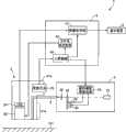
图1是表示本发明的实施例所涉及的内窥镜装置的主要部分的结构的图。FIG. 1 is a diagram showing the configuration of a main part of an endoscope apparatus according to an embodiment of the present invention.
图2是表示图1的内窥镜所具有的对物光学系统的结构的一例的图。FIG. 2 is a diagram showing an example of the configuration of an objective optical system included in the endoscope of FIG. 1 .
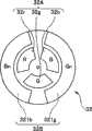
图3是表示图1的光源装置所具有的旋转滤波器的结构的一例的图。FIG. 3 is a diagram illustrating an example of a configuration of a rotary filter included in the light source device of FIG. 1 .
图4是表示图3的第一滤波器组所具有的各滤波器的透过特性的一例的图。FIG. 4 is a graph showing an example of transmission characteristics of filters included in the first filter bank in FIG. 3 .
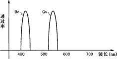
图5是表示图3的第二滤波器组所具有的各滤波器的透过特性的一例的图。FIG. 5 is a graph showing an example of transmission characteristics of filters included in the second filter bank of FIG. 3 .
具体实施方式Detailed ways
下面,参照附图来说明本发明的实施方式。图1至图5是本发明的实施例所涉及的图。Embodiments of the present invention will be described below with reference to the drawings. 1 to 5 are diagrams related to the embodiment of the present invention.
如图1所示,内窥镜装置1构成为具有:内窥镜2,其能够改变观察倍率,并且将拍摄到的被摄体101的图像作为摄像信号进行输出;光源装置3,其发出用于对被检者的体腔内的被摄体101进行照明的照明光;处理器4,其通过对来自内窥镜2的摄像信号进行图像处理来生成并输出影像信号;以及显示装置5,其显示与来自处理器4的影像信号相应的图像。As shown in FIG. 1 , an endoscope device 1 is configured to include: an
内窥镜2的内部插通有光导件(light guide)6,该光导件6用于将从光源装置3发出的照明光传送到内窥镜2的前端部21a。A
光导件6的一个端面(入射端面)与光源装置3相连接。另外,光导件6的另一个端面(射出端面)配置在设置于内窥镜2的前端部21a的未图示的照明光学系统的附近。通过这种结构,光源装置3所发出的照明光在经过光导件6和未图示的照明光学系统之后,向被摄体101射出。One end face (incident end face) of the
内窥镜2的前端部21a中设置有使被摄体的图像成像的对物光学系统22以及对经过了对物光学系统22的被摄体的图像进行摄像的CCD 24。另外,内窥镜2的基端侧(后端侧)的操作部21b中设置有用于进行变倍指示的变焦开关25。The
如图2所示,具备变倍功能的对物光学系统22具有:第一透镜组22a,其设置在前端部21a的最前端侧;可动光学系统22b,其能够沿着自身的光轴方向进行位移,从前面被入射通过了第一透镜组22a的光;焦点位置调整部22c,其能够使可动光学系统22b在沿着该光轴方向的方向(沿着图2的箭头D的方向)上移动;以及第二透镜组22d,其从前面被入射通过了可动光学系统22b的光。As shown in FIG. 2 , the objective
第一透镜组22a构成为具备位置各自固定的多个透镜,该多个透镜中至少包括被入射来自被摄体101的光的前端透镜22e。The
焦点位置调整部22c例如使用线性致动器来构成。具体地说,焦点位置调整部22c构成为具备:臂22f,其与可动光学系统22b的侧部相连接;以及臂驱动部22g,其根据处理器4的控制,使臂22f在沿着图2的箭头D的方向上进行移动。并且,根据这种结构,随着焦点位置调整部22c的动作而可动光学系统22b进行移动,由此能够分别改变对物光学系统22的焦点位置和观察倍率。The focus
第二透镜组22d构成为具备位置各自固定的多个透镜,使经由第一透镜组22a和可动光学系统22b入射的光在CCD 24的成像面上成像。The
具备作为观察倍率变更指示部的功能的变焦开关25构成为具备如下的按钮或操作杆等:在由使用者进行(按下等)操作的期间向处理器4持续输出变倍指示。并且,根据这种变焦开关25的结构,在由使用者操作变焦开关25的期间,对物光学系统22的观察倍率逐渐增大或减小。The zoom switch 25 functioning as an observation magnification change instructing unit is configured to include a button, a joystick, etc. that continuously output a magnification change instruction to the processor 4 while the user is operating (pressing, etc.). Furthermore, according to such a configuration of the zoom switch 25 , while the user operates the zoom switch 25 , the observation magnification of the objective
光源装置3具有:白色光源31,其由疝气灯等构成;旋转滤波器32,其将从白色光源31发出的白色光作为帧顺序式的照明光;马达33,其对旋转滤波器32进行旋转驱动;马达34,其使旋转滤波器32和马达33在与白色光源31的发射光路垂直的方向上移动;旋转滤波器驱动部35,其根据处理器4的控制来驱动马达33和34;以及聚光光学系统36,其会聚通过了旋转滤波器32的照明光并将其提供至光导件6的入射端面。The light source device 3 includes: a
如图3所示,旋转滤波器32构成为以中心为旋转轴的圆板状,具有:第一滤波器组32A,其具备沿着内周侧的圆周方向设置的多个滤波器;以及第二滤波器组32B,其具备沿着外周侧的圆周方向设置的多个滤波器。并且,通过向上述旋转轴传递马达33的驱动力,旋转滤波器32进行旋转。此外,设为在旋转滤波器32中,除了配置有第一滤波器组32A和第二滤波器组32B的各滤波器的部分之外,其它部分由遮光构件构成。As shown in FIG. 3 , the
第一滤波器组32A构成为具有分别沿着旋转滤波器32的内周侧的圆周方向设置的、使红色的波长频带的光透过的R滤波器32r、使绿色的波长频带的光透过的G滤波器32g以及使蓝色的波长频带的光透过的B滤波器32b。The
例如图4所示,R滤波器32r具有主要使600nm至700nm的光(R光)透过的结构。另外,例如图4所示,G滤波器32g具有主要使500nm至600nm的光(G光)透过的结构。并且,例如图4所示,B滤波器32b具有主要使400nm至500nm的光(B光)透过的结构。For example, as shown in FIG. 4, the
即,白色光源31所发出的白色光经过第一滤波器组32A,由此成为普通光观察模式用的宽频带光。That is, the white light emitted by the
第二滤波器组32B构成为具有分别沿着旋转滤波器32的外周侧的圆周方向设置的、使蓝色窄频带的光透过的Bn滤波器321b和使绿色窄频带的光透过的Gn滤波器321g。The
例如图5所示,Bn滤波器321b具有使B光的短波长侧的窄频带光(Bn光)透过的结构。For example, as shown in FIG. 5 , the
另外,例如图5所示,Gn滤波器321g具有使中心波长为540nm左右的窄频带光(Gn光)透过的结构。In addition, as shown in FIG. 5, for example, the
即,白色光源31所发出的白色光经过第二滤波器组32B而发生离散化,由此成为窄频带光观察模式用的多个频带的窄频带光。That is, the white light emitted by the
处理器4构成为具有:图像处理部41、光学系统控制部42、以及进行与变焦开关25的变倍指示相应的控制的主控制部43。The processor 4 is configured to include an
图像处理部41根据主控制部43的控制,对所输入的摄像信号按顺序进行噪声去除处理、A/D转换处理、图像生成处理以及D/A转换处理等处理,由此生成影像信号并输出到显示装置5。The
光学系统控制部42根据主控制部43的控制使焦点位置调整部22c进行动作,使得在与观察倍率相应的位置处配置可动光学系统22b。The optical
具备作为模式切换部的功能的主控制部43进行以下控制(切换普通光观察模式和窄频带光观察模式的控制):随时监视变焦开关25的变倍指示,根据监视结果来切换旋转滤波器驱动部35、图像处理部41以及光学系统控制部42的动作。The
在此,对内窥镜装置1的作用进行说明。此外,设为在接通电源时的初始状态下以等倍的观察倍率的普通光观察模式来启动内窥镜装置1的各部分,来进行之后的说明。Here, the operation of the endoscope device 1 will be described. In the following description, it is assumed that each part of the endoscope device 1 is activated in the normal light observation mode with an observation magnification of equal magnification in the initial state when the power is turned on.
随着处理器4的电源接通,主控制部43对旋转滤波器驱动部35、图像处理部41以及光学系统控制部42进行控制,使得各部分在等倍的观察倍率的普通光观察模式下进行动作。With the power of the processor 4 turned on, the
之后,旋转滤波器驱动部35根据主控制部43的控制,驱动马达33和34,使得第一滤波器组32A插入到白色光源31的光路上。另外,图像处理部41根据主控制部43的控制,进行用于根据被输入的摄像信号生成普通光观察图像(全色图像)的动作。并且,光学系统控制部42根据主控制部43的控制,使臂驱动部22g进行动作,使得可动光学系统22b配置在与等倍的观察倍率相应的位置处。After that, the rotary
使用者在接通内窥镜装置1的各部分的电源之后,一边观察显示装置5所显示的图像,一边使前端部21a向被检者的体腔内的被摄体101的附近移动。After turning on the power of each part of the endoscope apparatus 1 , the user moves the
并且,为了局部地观察被摄体101,使用者一边通过变焦开关25进行使观察倍率从低倍率侧逐渐向高倍率侧变化的变倍指示(例如一边保持按下变焦开关25的观察倍率增大侧的按钮的状态),一边进行使前端部21a靠近被摄体101的表面的动作。In addition, in order to partially observe the subject 101, the user performs a magnification change instruction to gradually change the observation magnification from the low magnification side to the high magnification side through the zoom switch 25 (for example, the observation magnification increases while keeping the zoom switch 25 pressed). The
另一方面,在通过变焦开关25进行从低倍率侧向高倍率侧变化的变倍指示的期间,主控制部43检测观察倍率从等倍起逐渐增大,并且继续控制光学系统控制部42。根据这种控制,光学系统控制部42使臂驱动部22a进行动作,使得可动光学系统22b从低倍率侧向高倍率侧移动。On the other hand, while the zoom switch 25 is instructing to change the magnification from the low magnification side to the high magnification side, the
在此,推测出当使用者在被摄体101的局部观察时进行这种动作时,观察倍率与从前端部21a到被摄体101表面的距离之间成立规定的相关关系。具体地说,推测出当观察倍率为低倍率时,从前端部21a到被摄体101表面的距离比较远。另外,推测出当观察倍率从低倍率逐渐向高倍率变化时,从前端部21a到被摄体101表面的距离逐渐接近。并且,推测出当观察倍率从高倍率逐渐向低倍率变化时,从前端部21a到被摄体101表面的距离逐渐变大。并且,在设为这种相关关系成立的情况下,认为如下规定的观察倍率与成为该规定的观察倍率时的从前端部21a到被摄体101表面的距离之间也成立同样的相关关系,所述的规定的观察倍率相当于即将能够通过窄频带光观察来观察被摄体101的粘膜表层的微小结构和毛细血管图案中的至少一方之前的观察倍率。Here, it is presumed that when the user performs such an operation while observing a part of the subject 101 , a predetermined correlation is established between the observation magnification and the distance from the
主控制部43随时监视与变焦开关25的变倍指示相应的观察倍率的增大,当检测到观察倍率变为大于等于上述规定的观察倍率时,视为从前端部21a到被摄体101表面的距离为适于窄频带光观察的距离,并对旋转滤波器驱动部35和图像处理部41进行用于以窄频带光观察模式进行动作的控制。The
之后,旋转滤波器驱动部35根据主控制部43的控制,驱动马达33和34,使得第二滤波器组32B插入到白色光源31的光路上。另外,图像处理部41根据主控制部43的控制,进行用于根据被输入的摄像信号生成窄频带观察图像(伪彩色图像)的动作。After that, the rotary
并且,根据如上所述的内窥镜装置1的作用,使用者能够一边观察显示装置5所显示的被摄体101的窄频带光观察图像,一边迅速地进行焦点调整。Furthermore, according to the functions of the endoscope apparatus 1 as described above, the user can quickly perform focus adjustment while viewing the narrow-band light observation image of the subject 101 displayed on the
此外,主控制部43根据变焦开关25的变倍指示的监视结果来检测是否通过观察倍率的增大而变为大于等于上述规定的观察倍率,但并不限于此,例如也可以根据可动光学系统22b的配置位置来进行检测,该可动光学系统22b的配置位置是根据光学系统控制部42的控制量的监视结果算出的。In addition, the
另外,只要上述规定的观察倍率是即将能够通过窄频带光观察来观察被摄体101的粘膜表层的微小结构和毛细血管图案中的至少一方之前的观察倍率,则既可以在显示装置所显示的输入画面等中适当设定为每个使用者所期望的观察倍率,也可以针对每个内窥镜独立地设定观察倍率,或者也可以是预先决定的固定的观察倍率。In addition, as long as the above-mentioned predetermined observation magnification is an observation magnification immediately before at least one of the microstructure of the mucous membrane surface layer of the subject 101 and the capillary pattern can be observed by narrow-band light observation, it may be displayed on the display device. The observation magnification desired by each user is appropriately set on the input screen or the like, and the observation magnification may be set independently for each endoscope, or may be a predetermined fixed observation magnification.
另一方面,当结束被摄体101的局部观察时,使用者一边通过变焦开关25进行使观察倍率从高倍率侧逐渐向低倍率侧变化的变倍指示(例如一边保持按下变焦开关25的观察倍率减小侧的按钮的状态),一边进行使前端部21a远离被摄体101的表面的动作。On the other hand, when the partial observation of the subject 101 is finished, the user gives an instruction to change the observation magnification gradually from a high magnification side to a low magnification side through the zoom switch 25 (for example, while keeping the zoom switch 25 pressed While observing the state of the button on the magnification reduction side), the
在通过变焦开关25进行从高倍率侧向低倍率侧变化的变倍指示的期间,主控制部43检测观察倍率从大于等于上述规定的观察倍率起逐渐减小,并且继续控制光学系统控制部42。根据这种控制,光学系统控制部42使臂驱动部22g进行动作,使得可动光学系统22b从高倍率侧向低倍率侧移动。While the zoom switch 25 is instructing to change the magnification from the high magnification side to the low magnification side, the
主控制部43随时监视与变焦开关25的变倍指示相应的观察倍率的减小,当检测到观察倍率小于上述规定的观察倍率时,视为从前端部21a到被摄体101表面的距离变为不适于窄频带光观察的距离,并对旋转滤波器驱动部35和图像处理部41进行用于以普通光观察模式进行动作的控制。The
之后,旋转滤波器驱动部35根据主控制部43的控制,驱动马达33和34,使得第一滤波器组32A插入到白色光源31的光路上。另外,图像处理部41根据主控制部43的控制,进行用于根据被输入的摄像信号来生成普通光观察图像(全色图像)的动作。After that, the rotary
此外,主控制部43根据变焦开关25的变焦指示的监视结果来检测是否通过观察倍率的减小而变为小于上述规定的观察倍率,但并不限于此,例如,也可以根据可动光学系统22b的配置位置来进行检测,该可动光学系统22b的配置位置是根据光学系统控制部42的控制量的监视结果算出的。In addition, the
如上所述,根据本实施例的内窥镜装置1,具有如下的结构和作用:在基于与变焦指示相应的观察倍率的增大的监视结果检测到观察倍率变为大于等于即将能够通过窄频带光观察来观察被摄体101的粘膜表层的微小结构和毛细血管图案中的至少一方之前的观察倍率时,进行从普通光观察模式向窄频带光观察模式的切换。即,根据本实施例的内窥镜装置1,具有如下的结构和作用:在使用者对存在于生物体内的被摄体的局部区域进行内窥镜观察时实际进行的动作中,在紧挨着需要调整焦点的时刻之前从普通光观察模式切换为窄频带光观察模式。其结果,根据本实施例的内窥镜装置1,能够与以往相比缩短对存在于生物体内的被摄体的局部区域进行内窥镜观察时的焦点调整所需的时间。As described above, according to the endoscope device 1 of the present embodiment, it has the following structure and action: when the monitoring result based on the increase of the observation magnification corresponding to the zoom instruction detects that the observation magnification becomes equal to or greater than the narrow frequency band When optical observation is used to observe at least one of the microstructure of the mucosal surface layer of the subject 101 and the capillary pattern at an observation magnification, switching is performed from the normal light observation mode to the narrowband light observation mode. That is, according to the endoscope apparatus 1 of the present embodiment, it has the following structure and function: in the action actually performed by the user when endoscopically observing a local area of a subject existing in the living body, Switch from normal light observation mode to narrowband light observation mode before the moment when the focus needs to be adjusted. As a result, according to the endoscope apparatus 1 of the present embodiment, it is possible to shorten the time required for focus adjustment when performing endoscopic observation of a local area of a subject existing in a living body, compared with conventional ones.
此外,本发明并不限于上述实施例,在不脱离发明的宗旨的范围内可以进行各种变更、应用,这是显然的。In addition, this invention is not limited to the said Example, It is obvious that various changes and applications are possible in the range which does not deviate from the summary of invention.
本申请主张2009年4月9日在日本申请的专利申请2009-95040号的优先权作为申请基础,上述公开内容被本申请的说明书、权利要求书以及说明书附图引用。This application claims the priority of the patent application No. 2009-95040 filed in Japan on April 9, 2009 as the application basis, and the above disclosure is cited by the specification, claims and drawings of the specification.
Claims (6)
Translated fromChineseApplications Claiming Priority (3)
| Application Number | Priority Date | Filing Date | Title |
|---|---|---|---|
| JP2009-095040 | 2009-04-09 | ||
| JP2009095040 | 2009-04-09 | ||
| PCT/JP2010/055415WO2010116902A1 (en) | 2009-04-09 | 2010-03-26 | Endoscopic device |
Publications (1)
| Publication Number | Publication Date |
|---|---|
| CN102387736Atrue CN102387736A (en) | 2012-03-21 |
Family
ID=42936188
Family Applications (1)
| Application Number | Title | Priority Date | Filing Date |
|---|---|---|---|
| CN2010800159997APendingCN102387736A (en) | 2009-04-09 | 2010-03-26 | Endoscopic device |
Country Status (5)
| Country | Link |
|---|---|
| US (1) | US20110270035A1 (en) |
| EP (1) | EP2417897A4 (en) |
| JP (2) | JPWO2010116902A1 (en) |
| CN (1) | CN102387736A (en) |
| WO (1) | WO2010116902A1 (en) |
Cited By (1)
| Publication number | Priority date | Publication date | Assignee | Title |
|---|---|---|---|---|
| CN109310285A (en)* | 2016-09-01 | 2019-02-05 | Hoya株式会社 | Electron mirror and electronic endoscope system |
Families Citing this family (18)
| Publication number | Priority date | Publication date | Assignee | Title |
|---|---|---|---|---|
| JP5274591B2 (en)* | 2011-01-27 | 2013-08-28 | 富士フイルム株式会社 | Endoscope system, processor device for endoscope system, and method for operating endoscope system |
| JP5292428B2 (en)* | 2011-03-22 | 2013-09-18 | 富士フイルム株式会社 | Endoscope system |
| US10215977B1 (en) | 2011-03-30 | 2019-02-26 | Designs For Vision, Inc. | Magnification device and assembly |
| US10852566B1 (en) | 2011-03-30 | 2020-12-01 | Designs For Vision, Inc. | Magnification device and assembly |
| US10061115B2 (en) | 2011-03-30 | 2018-08-28 | Designs For Vision, Inc. | Magnification device and assembly |
| WO2013115323A1 (en) | 2012-01-31 | 2013-08-08 | オリンパス株式会社 | Biological observation device |
| JP6473222B2 (en) | 2015-03-04 | 2019-02-20 | オリンパス株式会社 | Image processing apparatus, living body observation apparatus, and control method for image processing apparatus |
| JP6389140B2 (en)* | 2015-04-03 | 2018-09-12 | 富士フイルム株式会社 | Endoscope system, processor device, and operation method of endoscope system |
| JP6983067B2 (en)* | 2015-07-15 | 2021-12-17 | ソニーグループ株式会社 | Medical observation device and medical observation method |
| JP2018019975A (en)* | 2016-08-04 | 2018-02-08 | Hoya株式会社 | Turret-type optical element |
| EP3533382A4 (en) | 2016-10-27 | 2019-12-04 | Fujifilm Corporation | Endoscopic system |
| WO2018079217A1 (en) | 2016-10-27 | 2018-05-03 | 富士フイルム株式会社 | Endoscopic system and operation method thereof |
| CN114845625B (en)* | 2019-12-26 | 2025-08-26 | 富士胶片株式会社 | Endoscope system and operating method thereof |
| US11719925B2 (en) | 2020-04-21 | 2023-08-08 | Designs For Vision, Inc. | User wearable fluorescence enabled visualization system |
| US11547302B2 (en) | 2020-04-21 | 2023-01-10 | Designs For Vision, Inc. | User wearable fluorescence enabled visualization system |
| US10895735B1 (en) | 2020-05-05 | 2021-01-19 | Designs For Vision, Inc. | Magnification devices with filtering and method for selection of said filters |
| US12038630B1 (en) | 2022-11-18 | 2024-07-16 | Designs For Vision, Inc. | Telescopic image capture/recording device |
| US12332507B2 (en) | 2022-11-18 | 2025-06-17 | Designs For Vision, Inc. | Examination/visualization/collection system with light enhancement |
Citations (6)
| Publication number | Priority date | Publication date | Assignee | Title |
|---|---|---|---|---|
| JP2000019428A (en)* | 1998-06-29 | 2000-01-21 | Olympus Optical Co Ltd | Endoscopic device |
| JP2001174714A (en)* | 1999-12-15 | 2001-06-29 | Olympus Optical Co Ltd | Endoscopic device |
| JP2002045329A (en)* | 2000-08-01 | 2002-02-12 | Fuji Photo Film Co Ltd | Fluorescent device displaying diagnostic image |
| JP2002291682A (en)* | 2001-04-02 | 2002-10-08 | Olympus Optical Co Ltd | Endoscope system for fluorescent observation |
| WO2006028039A1 (en)* | 2004-09-08 | 2006-03-16 | Olympus Corporation | Endoscope |
| JP2007020728A (en)* | 2005-07-13 | 2007-02-01 | Olympus Medical Systems Corp | Image processing device |
Family Cites Families (7)
| Publication number | Priority date | Publication date | Assignee | Title |
|---|---|---|---|---|
| JPH11299730A (en)* | 1998-04-24 | 1999-11-02 | Olympus Optical Co Ltd | Endoscope device |
| US8998802B2 (en)* | 2006-05-24 | 2015-04-07 | Olympus Medical Systems Corp. | Endoscope, endoscopic apparatus, and examination method using endoscope |
| JP4847250B2 (en)* | 2006-08-03 | 2011-12-28 | オリンパスメディカルシステムズ株式会社 | Endoscope device |
| JP5041936B2 (en)* | 2007-09-12 | 2012-10-03 | オリンパスメディカルシステムズ株式会社 | Biological observation device |
| EP2179687B1 (en)* | 2008-10-22 | 2012-12-26 | FUJIFILM Corporation | Endoscope apparatus and control method therefor |
| JP2009095040A (en) | 2008-11-26 | 2009-04-30 | Kyocera Corp | Wireless communication system, mobile wireless communication device |
| JP5606120B2 (en)* | 2010-03-29 | 2014-10-15 | 富士フイルム株式会社 | Endoscope device |
- 2010
- 2010-03-26CNCN2010800159997Apatent/CN102387736A/enactivePending
- 2010-03-26EPEP10761602Apatent/EP2417897A4/ennot_activeWithdrawn
- 2010-03-26WOPCT/JP2010/055415patent/WO2010116902A1/enactiveApplication Filing
- 2010-03-26JPJP2010538240Apatent/JPWO2010116902A1/enactivePending
- 2010-10-07USUS12/899,828patent/US20110270035A1/ennot_activeAbandoned
- 2012
- 2012-07-31JPJP2012170283Apatent/JP2012245362A/enactivePending
Patent Citations (6)
| Publication number | Priority date | Publication date | Assignee | Title |
|---|---|---|---|---|
| JP2000019428A (en)* | 1998-06-29 | 2000-01-21 | Olympus Optical Co Ltd | Endoscopic device |
| JP2001174714A (en)* | 1999-12-15 | 2001-06-29 | Olympus Optical Co Ltd | Endoscopic device |
| JP2002045329A (en)* | 2000-08-01 | 2002-02-12 | Fuji Photo Film Co Ltd | Fluorescent device displaying diagnostic image |
| JP2002291682A (en)* | 2001-04-02 | 2002-10-08 | Olympus Optical Co Ltd | Endoscope system for fluorescent observation |
| WO2006028039A1 (en)* | 2004-09-08 | 2006-03-16 | Olympus Corporation | Endoscope |
| JP2007020728A (en)* | 2005-07-13 | 2007-02-01 | Olympus Medical Systems Corp | Image processing device |
Cited By (1)
| Publication number | Priority date | Publication date | Assignee | Title |
|---|---|---|---|---|
| CN109310285A (en)* | 2016-09-01 | 2019-02-05 | Hoya株式会社 | Electron mirror and electronic endoscope system |
Also Published As
| Publication number | Publication date |
|---|---|
| JPWO2010116902A1 (en) | 2012-10-18 |
| WO2010116902A1 (en) | 2010-10-14 |
| EP2417897A4 (en) | 2012-11-07 |
| US20110270035A1 (en) | 2011-11-03 |
| JP2012245362A (en) | 2012-12-13 |
| EP2417897A1 (en) | 2012-02-15 |
Similar Documents
| Publication | Publication Date | Title |
|---|---|---|
| CN102387736A (en) | Endoscopic device | |
| JP4875319B2 (en) | Endoscope | |
| JP5127639B2 (en) | Endoscope system and method of operating the same | |
| JP5203861B2 (en) | Endoscope system and method of operating the same | |
| JP4884574B2 (en) | Light source device and endoscope system | |
| US11653824B2 (en) | Medical observation system and medical observation device | |
| CN109195502B (en) | Living body observation system | |
| JP5292428B2 (en) | Endoscope system | |
| CN109963490B (en) | Branching optical system, imaging device, and imaging system | |
| JP2009034224A (en) | Medical equipment | |
| AU2006305419A1 (en) | Organism imaging device and organism observing system | |
| WO2019176253A1 (en) | Medical observation system | |
| JP5455733B2 (en) | Light source device for electronic endoscope | |
| WO2017126388A1 (en) | Medical light source device and medical observation system | |
| JP6355877B2 (en) | Endoscope device | |
| JP2011200380A (en) | Light source device for electronic endoscope | |
| JP5467966B2 (en) | Endoscope system | |
| JP5897663B2 (en) | Endoscope device | |
| JP4067358B2 (en) | Endoscope device | |
| JP5455734B2 (en) | Light source device for electronic endoscope | |
| JP5438550B2 (en) | Imaging optical system for endoscope and endoscope system | |
| JP5371941B2 (en) | Endoscope system | |
| JP3756598B2 (en) | Endoscope device | |
| WO2014054742A1 (en) | Endoscope system and control method therefor | |
| JP2004180953A (en) | Optical system for light source |
Legal Events
| Date | Code | Title | Description |
|---|---|---|---|
| C06 | Publication | ||
| PB01 | Publication | ||
| C10 | Entry into substantive examination | ||
| SE01 | Entry into force of request for substantive examination | ||
| C02 | Deemed withdrawal of patent application after publication (patent law 2001) | ||
| WD01 | Invention patent application deemed withdrawn after publication | Application publication date:20120321 |