CN102386513A - Reinforced connector - Google Patents
Reinforced connectorDownload PDFInfo
- Publication number
- CN102386513A CN102386513ACN2011103373081ACN201110337308ACN102386513ACN 102386513 ACN102386513 ACN 102386513ACN 2011103373081 ACN2011103373081 ACN 2011103373081ACN 201110337308 ACN201110337308 ACN 201110337308ACN 102386513 ACN102386513 ACN 102386513A
- Authority
- CN
- China
- Prior art keywords
- insulator
- positioning
- press
- metal sleeve
- end surface
- Prior art date
- Legal status (The legal status is an assumption and is not a legal conclusion. Google has not performed a legal analysis and makes no representation as to the accuracy of the status listed.)
- Granted
Links
Images


Landscapes
- Connector Housings Or Holding Contact Members (AREA)
Abstract
Translated fromChinese
Description
Translated fromChinese技术领域technical field
本发明涉及一种用于电流或信号转接的连接器,尤其涉及一种接触件与绝缘体之间的配合可靠的加强连接器。The invention relates to a connector for current or signal transfer, in particular to a reinforced connector with reliable cooperation between a contact piece and an insulator.
背景技术Background technique
现有一种连接器如图1、2所示,包括壳体1,壳体1内设置有贯穿前后的通孔,壳体的通孔内通过绝缘部件固定设置上有接触件2,绝缘部件包括固定设置在壳体1内的前绝缘体4与后绝缘体,后绝缘体的后方还设置有尾部绝缘体。接触件2穿设在前绝缘体、后绝缘体与尾部绝缘体的内孔中。前绝缘体4的前端部设置在内翻的固定翻沿5。接触件2通过定位爪3实现在绝缘部件内的定位,定位爪3包括一个筒状体,筒状体的内壁上设置有一端固定在筒状体的内壁上,另一端自由倾斜伸向筒状体的轴线的定位弹片,定位爪3通过其筒状体套设在接触件2上,定位爪处于前绝缘体的内孔中。定位爪的前端面顶压在前绝缘体4的固定翻沿5的外缘部位,定位爪的后端面顶压在后绝缘体的前端面上。接触件2上设置有定位轴环6,定位轴环6的前端面顶压在前绝缘体4的固定翻沿5的内缘部位,定位轴环6的后端面与定位爪的定位弹片顶压配合,从而实现接触件在壳体1内的固定。在装配时,是先将前绝缘体装配在壳体1的内孔中,然后将定位爪插设在前绝缘体4的内孔中,再依次装上后绝缘体与尾部绝缘体,最后从后端将接触件2穿入各个绝缘体的内孔中,当定位轴环碰触到定位爪的定位弹片时,会挤压定位弹片,使定位弹片弹性变形,当定位轴环越过定位弹片后,定位弹片恢复原状并与定位轴环的后端面顶压。由于接触件需要克服定位弹片的弹力,因此在装配时需要在接触件上施加一定的推压力,在操作时,如果推压力的大小控制不好,接触件的定位轴环就会撞到前绝缘体的固定翻沿,由于结构限制,固定翻沿的轴向尺寸较小,一般只有0.76-1.1mm,这就使得固定翻沿很容易被接触件撞破,造成前绝缘体损坏。As shown in Figures 1 and 2, there is an existing connector, which includes a housing 1, and a through hole passing through the front and back is arranged in the housing 1, and a
发明内容Contents of the invention
本发明的目的在于提供一种加强连接器,以解决现有技术中在连接器装配时出现的接触件将前绝缘体的固定翻沿撞破造成前绝缘体损坏的问题。The purpose of the present invention is to provide a reinforced connector to solve the problem in the prior art that the fixed edge of the front insulator is broken by the contact piece when the connector is assembled, causing damage to the front insulator.
为实现上述目的,本发明采用如下技术方案:一种加强连接器,包括壳体,壳体的贯穿前后的内孔中通过绝缘部件固定设置有接触件,接触件上具有定位轴环,绝缘部件固定设置在壳体内,绝缘部件包括前绝缘体和后绝缘体,接触件通过定位爪固定在前绝缘体与后绝缘体的内孔中,所述定位爪通过插设在前绝缘体的内孔内的金属套筒将接触件固定在前绝缘体与后绝缘体的内孔中,金属套筒的外周面上具有朝向前端的定位台阶面,定位台阶面与前绝缘体顶压配合,金属套筒的后端面与后绝缘体的前端部顶压配合,金属套筒的前端部设置有内翻的定位翻沿,定位爪的前端面与定位翻沿的外缘部分顶压配合,定位爪的后端面与后绝缘体的前端部顶压配合,所述定位轴环的前端面与定位翻沿的内缘部分顶压配合,定位轴环的后端面与定位爪的定位弹片顶压配合。 In order to achieve the above object, the present invention adopts the following technical solutions: a reinforced connector, including a housing, a contact piece is fixedly arranged in the inner hole of the housing through the front and back through an insulating component, the contact piece has a positioning collar, and the insulating component Fixedly arranged in the housing, the insulating part includes a front insulator and a rear insulator, and the contact piece is fixed in the inner holes of the front insulator and the rear insulator by positioning claws, and the positioning claws pass through the metal sleeve inserted in the inner hole of the front insulator Fix the contact piece in the inner hole of the front insulator and the rear insulator. The outer peripheral surface of the metal sleeve has a positioning step surface facing the front end. The positioning step surface is press-fitted with the front insulator. The front end is press-fitted. The front end of the metal sleeve is provided with an inward-turned positioning edge. The front end of the positioning claw is press-fitted with the outer edge of the positioning edge. The rear end of the positioning claw is pressed against the front end of the rear insulator. Press-fitting, the front end face of the positioning collar is press-fitted with the inner edge part of the positioning flange, and the rear end face of the positioning collar is press-fitted with the positioning shrapnel of the positioning claw. the
所述的定位台阶面为设置在金属套筒的后端部的外凸的定位凸缘的前端面。The positioning stepped surface is the front end surface of the outwardly protruding positioning flange provided at the rear end of the metal sleeve.
所述前绝缘体的后端面上于定位凸缘处设置有设置沉孔,设置沉孔的轴线与前绝缘体的内孔的轴线重合,所述定位台阶面通过与设置沉孔的端面的顶压配合与前绝缘体顶压配合。The rear end surface of the front insulator is provided with a counterbore at the positioning flange, the axis of the counterbore coincides with the axis of the inner hole of the front insulator, and the positioning step surface is press fit with the end surface of the counterbore. Press fit with front insulator top.
所述定位凸缘的后端面与金属套筒的后端面平齐,金属套筒的后端面与前绝缘体的后端面平齐。The rear end face of the positioning flange is flush with the rear end face of the metal sleeve, and the rear end face of the metal sleeve is flush with the rear end face of the front insulator.
所述的后绝缘体的后方设置有尾部绝缘体,尾部绝缘体处于壳体的内孔尾部,尾部绝缘体通过其内孔套设在接触件上。A tail insulator is arranged behind the rear insulator, and the tail insulator is located at the tail of the inner hole of the shell, and the tail insulator is sheathed on the contact piece through the inner hole.
本发明的前绝缘体的内孔中插设有金属套筒,金属套筒与前、后绝缘体顶压配合,定位爪的前端顶压在金属套筒的定位翻沿的外缘部位,定位爪的后端顶压在后绝缘体上,接触件的定位轴环的前端面顶压在定位翻沿的内缘部位,定位轴环的后端面与定位爪的定位弹片顶压配合,在装配时,向接触件上施加推压力,接触件挤压定位弹片以使得接触件的定位轴环越过定位弹片,由于金属套筒的材料为金属,强度较大,即便施加在接触件上的推压力较大,接触件也不会将定位翻沿撞破,金属套筒的设置增强了整个连接器的强度。In the inner hole of the front insulator of the present invention, a metal sleeve is inserted, and the metal sleeve is press-fitted with the front and rear insulators. The rear end presses against the rear insulator, the front end of the positioning collar of the contact piece presses against the inner edge of the positioning flange, and the rear end of the positioning collar is press-fitted with the positioning shrapnel of the positioning claw. A push force is applied to the contact piece, and the contact piece squeezes the positioning shrapnel so that the positioning collar of the contact piece passes over the positioning shrapnel. Since the material of the metal sleeve is metal, the strength is relatively high, even if the pushing force applied to the contact piece is large, The contact piece will not break the positioning edge, and the arrangement of the metal sleeve enhances the strength of the entire connector.
附图说明Description of drawings
图1是现有技术中的连接器的结构示意图;Fig. 1 is a structural schematic diagram of a connector in the prior art;
图2是图1中A处的局部放大图;Fig. 2 is a partial enlarged view of place A in Fig. 1;
图3是本发明的实施例的结构示意图;Fig. 3 is the structural representation of the embodiment of the present invention;
图4是图3中的接触件与金属套筒和前绝缘体的装配图;Fig. 4 is the assembly drawing of contact piece among Fig. 3 and metal sleeve and front insulator;
图5是图3中的金属套筒和前绝缘体的装配图;Fig. 5 is the assembly drawing of metal sleeve and front insulator among Fig. 3;
图6是图3中的金属套筒的结构示意图。Fig. 6 is a structural schematic diagram of the metal sleeve in Fig. 3 .
具体实施方式Detailed ways
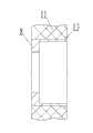
一种加强连接器的实施例,在图3-6中,加强连接器的壳体9内具有贯穿前后的内孔,壳体9的内孔中固定设置有绝缘部件,绝缘部件包括轴向叠压设置的前绝缘体11与后绝缘体,后绝缘体的后方还设置有尾部绝缘体,各个绝缘体均具有内孔,各个绝缘体的内孔中穿设有接触件7,接触件7通过定位爪10固定在前绝缘体11与后绝缘体之间。定位爪10为现有技术中的定位爪,由一个筒状体和该筒状体的内壁上设置的定位弹片组成,定位弹片的一端固定在筒状体的内壁上,另一端自由倾斜伸向筒状体的轴线。定位爪10通过其筒状体套设在接触件7上,定位爪10处于前绝缘体11的内孔中,定位爪10与前绝缘体11的内孔孔壁之间设置有金属套筒8,金属套筒8套设在定位爪10的外周,金属套筒8插设在前绝缘体11的内孔中。金属套筒8的外周面后部向外凸设有外凸的定位凸缘13,定位凸缘13的后端面与金属套筒的后端面平齐,定位凸缘13的前端面为定位台阶面。前绝缘体11的后端面上设置有与其内孔同轴线的设置沉孔,定位凸缘13处于该设置沉孔中,定位台阶面与设置沉孔的端面顶压配合,实现金属套筒与前绝缘体11的前端定位。金属套筒8的后端面与前绝缘体11的后端面平齐,金属套筒8的后端面与后绝缘体的前端面顶压配合,实现金属套筒8与后绝缘体的后端定位,从而实现金属套筒8在绝缘部件内的定位。An embodiment of a reinforced connector, in Fig. 3-6, the housing 9 of the reinforced connector has an inner hole through the front and back, and an insulating part is fixedly arranged in the inner hole of the housing 9, and the insulating part includes an axially stacked The
金属套筒8的前端部具有内翻的定位翻沿14,定位爪10的前端面与定位翻沿14的外缘部分顶压配合,定位爪10的后端面与后绝缘体的前端部顶压配合。接触件7的外周面上与定位翻沿14的配合处设置有定位轴环12,定位轴环12的前端面与定位翻沿14的内缘部分顶压配合,定位轴环12的后端面与定位弹片顶压配合,实现接触件与前绝缘体和后绝缘体的轴向固定,进而实现接触件在壳体9内的固定。The front end of the
上述实施例中的定位台阶面处于金属套筒的后端部,也可以处于金属套筒的中间部位或是前部。In the above embodiments, the positioning stepped surface is located at the rear end of the metal sleeve, and may also be located at the middle or front of the metal sleeve.
上述实施例中的定位凸缘处于前绝缘体的后端面上设置的设置沉孔中,也可以将设置沉孔去掉,使定位台阶面直接顶压在前绝缘体的后端面上,这时前绝缘体与后绝缘体不接触,两者之间具有间隙,也可以将设置沉孔设置在后绝缘体的前端面上。The positioning flange in the above embodiment is located in the setting counterbore provided on the rear end surface of the front insulator, and the setting counterbore can also be removed so that the positioning step surface is directly pressed against the rear end surface of the front insulator. At this time, the front insulator and the The rear insulator is not in contact, and there is a gap between the two, and the setting counterbore can also be arranged on the front end surface of the rear insulator.
上述实施例中设置了尾部绝缘体,也可以不设置尾部绝缘体,使后绝缘体向后延伸即可。In the above embodiments, the tail insulator is provided, and the tail insulator may not be provided, and the rear insulator only needs to extend backward.
Claims (5)
Translated fromChinesePriority Applications (1)
| Application Number | Priority Date | Filing Date | Title |
|---|---|---|---|
| CN201110337308.1ACN102386513B (en) | 2011-10-31 | 2011-10-31 | Reinforced connector |
Applications Claiming Priority (1)
| Application Number | Priority Date | Filing Date | Title |
|---|---|---|---|
| CN201110337308.1ACN102386513B (en) | 2011-10-31 | 2011-10-31 | Reinforced connector |
Publications (2)
| Publication Number | Publication Date |
|---|---|
| CN102386513Atrue CN102386513A (en) | 2012-03-21 |
| CN102386513B CN102386513B (en) | 2015-04-22 |
Family
ID=45825644
Family Applications (1)
| Application Number | Title | Priority Date | Filing Date |
|---|---|---|---|
| CN201110337308.1AExpired - Fee RelatedCN102386513B (en) | 2011-10-31 | 2011-10-31 | Reinforced connector |
Country Status (1)
| Country | Link |
|---|---|
| CN (1) | CN102386513B (en) |
Cited By (1)
| Publication number | Priority date | Publication date | Assignee | Title |
|---|---|---|---|---|
| CN106532335A (en)* | 2016-12-30 | 2017-03-22 | 珠海市业成轨道交通设备科技有限公司 | Insulator structure with embedded metal inserts of connector for high-speed motor car |
Citations (5)
| Publication number | Priority date | Publication date | Assignee | Title |
|---|---|---|---|---|
| US4746305A (en)* | 1986-09-17 | 1988-05-24 | Taisho Electric Industrial Co. Ltd. | High frequency coaxial connector |
| CN1585195A (en)* | 2003-06-20 | 2005-02-23 | 马斯普罗电工株式会社 | Connector for coaxial cable and electronic device case |
| CN201946850U (en)* | 2010-12-15 | 2011-08-24 | 中航光电科技股份有限公司 | Coaxial connector for preventing contact element from tilting |
| CN202019120U (en)* | 2010-12-15 | 2011-10-26 | 中航光电科技股份有限公司 | Coaxial connector |
| CN202352881U (en)* | 2011-10-31 | 2012-07-25 | 中航光电科技股份有限公司 | Reinforced connector |
- 2011
- 2011-10-31CNCN201110337308.1Apatent/CN102386513B/ennot_activeExpired - Fee Related
Patent Citations (5)
| Publication number | Priority date | Publication date | Assignee | Title |
|---|---|---|---|---|
| US4746305A (en)* | 1986-09-17 | 1988-05-24 | Taisho Electric Industrial Co. Ltd. | High frequency coaxial connector |
| CN1585195A (en)* | 2003-06-20 | 2005-02-23 | 马斯普罗电工株式会社 | Connector for coaxial cable and electronic device case |
| CN201946850U (en)* | 2010-12-15 | 2011-08-24 | 中航光电科技股份有限公司 | Coaxial connector for preventing contact element from tilting |
| CN202019120U (en)* | 2010-12-15 | 2011-10-26 | 中航光电科技股份有限公司 | Coaxial connector |
| CN202352881U (en)* | 2011-10-31 | 2012-07-25 | 中航光电科技股份有限公司 | Reinforced connector |
Cited By (1)
| Publication number | Priority date | Publication date | Assignee | Title |
|---|---|---|---|---|
| CN106532335A (en)* | 2016-12-30 | 2017-03-22 | 珠海市业成轨道交通设备科技有限公司 | Insulator structure with embedded metal inserts of connector for high-speed motor car |
Also Published As
| Publication number | Publication date |
|---|---|
| CN102386513B (en) | 2015-04-22 |
Similar Documents
| Publication | Publication Date | Title |
|---|---|---|
| CN106981756A (en) | A kind of electric connector and its hat spring socket | |
| CN103490200B (en) | A kind of radio frequency coaxial electric connector with punching press contact element | |
| CN202633583U (en) | Radio-frequency connector and contact element thereof | |
| CN104505620A (en) | High-current jack contact | |
| CN202352881U (en) | Reinforced connector | |
| CN106953188B (en) | An adapter connector | |
| CN102522664B (en) | Shielded connector component and plug thereof | |
| CN102386513B (en) | Reinforced connector | |
| CN202076469U (en) | Contact component and fixing clamp ring thereof | |
| CN104538807A (en) | Large current electric connector | |
| CN104183978B (en) | One can automatically reset float connector | |
| CN202454827U (en) | Shielding connector assembly and plug thereof | |
| CN101630789B (en) | Electric connector jack | |
| CN204464546U (en) | A T-SMP radio frequency connector structure | |
| CN203481518U (en) | High-precision push-and-pull self-locking circular plug | |
| CN204905511U (en) | Electric connector insulator subassembly | |
| CN101677167B (en) | Differential contact double pins and corresponding socket and plug thereof | |
| CN204361398U (en) | A kind of combining structure realizing electrical connector and reliably pull away | |
| CN201397954Y (en) | Fast-mating coaxial connector | |
| CN201266703Y (en) | Contact member and plug, socket with the same | |
| CN104183946B (en) | Adapter jack contact | |
| CN110176680A (en) | A kind of contact and the connector using the contact | |
| CN203351818U (en) | High-frequency floating contact for connector | |
| CN204103078U (en) | SMA connector | |
| CN201698249U (en) | Compression ring and switching element using the same |
Legal Events
| Date | Code | Title | Description |
|---|---|---|---|
| C06 | Publication | ||
| PB01 | Publication | ||
| C10 | Entry into substantive examination | ||
| SE01 | Entry into force of request for substantive examination | ||
| C14 | Grant of patent or utility model | ||
| GR01 | Patent grant | ||
| CF01 | Termination of patent right due to non-payment of annual fee | Granted publication date:20150422 Termination date:20181031 | |
| CF01 | Termination of patent right due to non-payment of annual fee |