CN102376089A - Target correction method and system - Google Patents
Target correction method and systemDownload PDFInfo
- Publication number
- CN102376089A CN102376089ACN201010580900XACN201010580900ACN102376089ACN 102376089 ACN102376089 ACN 102376089ACN 201010580900X ACN201010580900X ACN 201010580900XACN 201010580900 ACN201010580900 ACN 201010580900ACN 102376089 ACN102376089 ACN 102376089A
- Authority
- CN
- China
- Prior art keywords
- points
- target
- point
- marker
- dimensional coordinates
- Prior art date
- Legal status (The legal status is an assumption and is not a legal conclusion. Google has not performed a legal analysis and makes no representation as to the accuracy of the status listed.)
- Granted
Links
Images


Landscapes
- Length Measuring Devices By Optical Means (AREA)
Abstract
Translated fromChinese
Description
Translated fromChinese技术领域technical field
本发明属于机器视觉技术、三维测量领域,尤其涉及对摄像机标定的标靶制作及校正。The invention belongs to the field of machine vision technology and three-dimensional measurement, and in particular relates to the production and correction of a target for camera calibration.
背景技术Background technique
摄像机标定是计算机视觉和三维测量领域的关键技术,而摄像机标定均需要一个高精度标靶,而且标靶的精度决定了摄像机标定及测量的精度。通常一个高精密的标靶制作加工复杂、成本较高;目前,仅对于获取一个精度达到微米级的二维平面标靶来说,通常有两种方式:第一种,需要高精密加工仪器,以保证标靶上标志点的距离精度达到微米级;第二种,借用微米级精度的二维影像仪测量出所有标志点的间距或坐标。这两种方法均比较复杂,且成本较高。因此,一种简易方便、低成本的标靶校正方法对摄像机标定具有重要意义。自Zhang提出了基于二维平面标靶的摄像机标定技术(Z.Zhang.“A flexible newtechnique for camera calibration”.IEEE Transactions on Pattern Analysis andMachine Intelligence,22(11):1330-1334,2000)以来,其获得了广泛的发展与应用。但该方法须以标靶上所有标志点坐标为已知条件。一般的平面标靶,以圆形标志点为例,其标志点的形状(圆度和边缘)可以达到精度要求,但其圆心的坐标精度较难保证。如果用其它手段(如用二维影像测量仪)逐一测量标志点的准确位置,往往费时费力。Camera calibration is a key technology in the field of computer vision and three-dimensional measurement, and camera calibration requires a high-precision target, and the accuracy of the target determines the accuracy of camera calibration and measurement. Usually a high-precision target is complicated to manufacture and process, and the cost is high; at present, there are usually two ways to obtain a two-dimensional planar target with an accuracy of micron level: the first one requires high-precision processing equipment, In order to ensure that the distance accuracy of the marking points on the target reaches the micron level; the second is to use a two-dimensional imager with micron level precision to measure the distance or coordinates of all the marking points. These two methods are relatively complicated and costly. Therefore, a simple, convenient and low-cost target calibration method is of great significance for camera calibration. Since Zhang proposed a camera calibration technology based on a two-dimensional planar target (Z. Zhang. "A flexible new technique for camera calibration". IEEE Transactions on Pattern Analysis and Machine Intelligence, 22(11): 1330-1334, 2000), its It has been widely developed and applied. However, this method must take the coordinates of all marker points on the target as known conditions. For general planar targets, taking the circular mark point as an example, the shape (roundness and edge) of the mark point can meet the accuracy requirements, but the coordinate accuracy of the center of the circle is difficult to guarantee. If other means (such as a two-dimensional image measuring instrument) are used to measure the exact positions of the marker points one by one, it is often time-consuming and labor-intensive.
发明内容Contents of the invention
本发明实施例的目的在于提供一种操作简易、成本较低且适用于不同尺寸标靶的校正方法,以准确获取所有标志点的坐标,定位精度可达到微米级。The purpose of the embodiments of the present invention is to provide a calibration method that is easy to operate, low in cost and applicable to targets of different sizes, so as to accurately obtain the coordinates of all marker points, and the positioning accuracy can reach the micron level.
本发明实施例是这样实现的,一种标靶校正方法,包括以下步骤:The embodiment of the present invention is achieved in this way, a target calibration method, comprising the following steps:
从不同角度获取标靶的多幅图像,所述标靶设有多个标志点;acquiring multiple images of the target from different angles, the target being provided with multiple marker points;
分别提取各图像中标志点的中心作为特征点;Extract the centers of the marker points in each image as feature points respectively;
建立各幅图像间同名标志点的对应关系;Establish the corresponding relationship between the same-named marker points between each image;
计算所述特征点的三维坐标,所述特征点的三维坐标由尺度因子所约束;calculating the three-dimensional coordinates of the feature points, where the three-dimensional coordinates of the feature points are constrained by a scale factor;
获取所述尺度因子,将各特征点的三维坐标缩放至实际尺寸。The scale factor is obtained, and the three-dimensional coordinates of each feature point are scaled to an actual size.
本发明实施例的另一目的在于提供一种标靶校正系统,所述系统包括:Another object of the embodiments of the present invention is to provide a target calibration system, the system comprising:
图像采集模块,用于从不同角度获取标靶的多幅图像,所述标靶设有多个标志点;An image acquisition module, configured to acquire multiple images of the target from different angles, and the target is provided with a plurality of marker points;
提取模块,用于分别提取各图像中标志点的中心作为特征点;Extraction module, for extracting respectively the center of mark point in each image as feature point;
识别模块,用于建立各幅图像间同名标志点的对应关系;The recognition module is used to establish the corresponding relationship between the same-named marker points between the images;
运算模块,用于计算所述特征点的三维坐标,所述特征点的三维坐标由尺度因子所约束;An operation module, configured to calculate the three-dimensional coordinates of the feature points, where the three-dimensional coordinates of the feature points are constrained by a scale factor;
缩放模块,用于获取所述尺度因子,将各特征点的三维坐标缩放至实际尺寸。The scaling module is configured to obtain the scale factor, and scale the three-dimensional coordinates of each feature point to an actual size.
本发明实施例先从不同角度拍摄标靶,获取多幅图像,分别提取各图像中标志点的中心作为特征点,建立各幅图像间同名标志点的对应关系,计算特征点的三维坐标,该特征点的三维坐标由尺度因子所约束,最后获取尺度因子,将各特征点的三维坐标缩放至实际尺寸,经本方法制作及校正的标靶具有较高的精度,操作简易,成本低。因而本方法及系统可广泛适用于视觉测量及系统标定。In the embodiment of the present invention, the target is first photographed from different angles, multiple images are obtained, the centers of the marker points in each image are respectively extracted as feature points, the corresponding relationship between the marker points with the same name is established in each image, and the three-dimensional coordinates of the feature points are calculated. The three-dimensional coordinates of the feature points are constrained by the scale factor. Finally, the scale factor is obtained, and the three-dimensional coordinates of each feature point are scaled to the actual size. The target made and calibrated by this method has high precision, easy operation, and low cost. Therefore, the method and system can be widely used in visual measurement and system calibration.
附图说明Description of drawings
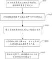
图1是本发明实施例提供的标靶校正方法的实现流程图;Fig. 1 is a flow chart of the implementation of the target calibration method provided by the embodiment of the present invention;
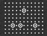
图2是本发明实施例中平面标靶的结构示意图;Fig. 2 is a schematic structural view of a planar target in an embodiment of the present invention;
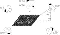
图3是本发明实施例中数码单反相机拍摄标靶的角度示意图;Fig. 3 is a schematic diagram of the angle of a target shot by a digital SLR camera in an embodiment of the present invention;
图4是本发明实施例中标靶编号及拓扑关系示意图;Fig. 4 is a schematic diagram of target numbers and topological relationships in an embodiment of the present invention;
图5是本发明实施例中摄影测量结果及数码单反相机与标靶的位置关系图;Fig. 5 is a photogrammetry result and a positional relationship diagram between a digital SLR camera and a target in an embodiment of the present invention;
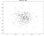
图6是本发明实施例中摄影测量的重投影误差分布图;Fig. 6 is a reprojection error distribution diagram of photogrammetry in an embodiment of the present invention;
图7是本发明实施例中条纹投影测量系统的结构示意图;7 is a schematic structural diagram of a fringe projection measurement system in an embodiment of the present invention;
图8是本发明实施例中标准球的三维图;Fig. 8 is the three-dimensional figure of standard ball in the embodiment of the present invention;
图9是本发明实施例提供的标靶校正系统图。Fig. 9 is a diagram of a target calibration system provided by an embodiment of the present invention.
具体实施方式Detailed ways
为了使本发明的目的、技术方案及优点更加清楚明白,以下结合附图及实施例,对本发明进行进一步详细说明。应当理解,此处所描述的具体实施例仅仅用以解释本发明,并不用于限定本发明。In order to make the object, technical solution and advantages of the present invention clearer, the present invention will be further described in detail below in conjunction with the accompanying drawings and embodiments. It should be understood that the specific embodiments described here are only used to explain the present invention, not to limit the present invention.
本发明实施例先从不同角度拍摄标靶,获取多幅图像,分别提取各图像中标志点的中心作为特征点,建立各幅图像间同名标志点的对应关系,计算特征点的三维坐标,该特征点的三维坐标由尺度因子所约束,最后获取尺度因子,将各特征点的三维坐标缩放至实际尺寸,经本方法制作及校正的标靶具有较高的精度,操作简易,成本低。In the embodiment of the present invention, the target is first photographed from different angles, multiple images are obtained, the centers of the marker points in each image are respectively extracted as feature points, the corresponding relationship between the marker points with the same name is established in each image, and the three-dimensional coordinates of the feature points are calculated. The three-dimensional coordinates of the feature points are constrained by the scale factor. Finally, the scale factor is obtained, and the three-dimensional coordinates of each feature point are scaled to the actual size. The target made and calibrated by this method has high precision, easy operation, and low cost.
本发明实施例提供的标靶校正方法包括以下步骤:The target calibration method provided by the embodiment of the present invention includes the following steps:
从不同角度获取标靶的多幅图像,所述标靶设有多个标志点;acquiring multiple images of the target from different angles, the target being provided with multiple marker points;
分别提取各图像中标志点的中心作为特征点;Extract the centers of the marker points in each image as feature points respectively;
建立各幅图像间同名标志点的对应关系;Establish the corresponding relationship between the same-named marker points between each image;
计算所述特征点的三维坐标,所述特征点的三维坐标由尺度因子所约束;calculating the three-dimensional coordinates of the feature points, where the three-dimensional coordinates of the feature points are constrained by a scale factor;
获取所述尺度因子,将各特征点的三维坐标缩放至实际尺寸。The scale factor is obtained, and the three-dimensional coordinates of each feature point are scaled to an actual size.
本发明实施例提供的标靶校正系统包括:The target calibration system provided by the embodiment of the present invention includes:
图像采集模块,用于从不同角度获取标靶的多幅图像,所述标靶设有多个标志点;An image acquisition module, configured to acquire multiple images of the target from different angles, and the target is provided with a plurality of marker points;
提取模块,用于分别提取各图像中标志点的中心作为特征点;Extraction module, for extracting respectively the center of mark point in each image as feature point;
识别模块,用于建立各幅图像间同名标志点的对应关系;The recognition module is used to establish the corresponding relationship between the same-named marker points between the images;
运算模块,用于计算所述特征点的三维坐标,所述特征点的三维坐标由尺度因子所约束;An operation module, configured to calculate the three-dimensional coordinates of the feature points, where the three-dimensional coordinates of the feature points are constrained by a scale factor;
缩放模块,用于获取所述尺度因子,将各特征点的三维坐标缩放至实际尺寸。The scaling module is configured to obtain the scale factor, and scale the three-dimensional coordinates of each feature point to an actual size.
以下结合具体实施例对本发明的实现进行详细描述。The implementation of the present invention will be described in detail below in conjunction with specific embodiments.
图1示出了本发明实施例提供的标靶校正方法的实现流程,详述如下:Figure 1 shows the implementation process of the target calibration method provided by the embodiment of the present invention, which is described in detail as follows:
在步骤S101中,从不同角度获取标靶的多幅图像,该标靶设有多个标志点;In step S101, multiple images of the target are acquired from different angles, and the target is provided with multiple marker points;
本发明实施例于一发黑的金属板或陶瓷板印刷或粘贴多个白色标志点制成平面标靶,标志点的图案具有多种(如方形、圆形),优选为圆形,如图2所示。图2所示的标靶具有99个圆形标志点,其中外围套圆环的4个标志点(以下简称圆环点)仅用于标识99个标志点的位置拓扑关系,以自动识别各个标志点。该图案中每个标志点间距大致相同,其精度取决于印刷精度。In the embodiment of the present invention, a plurality of white mark points are printed or pasted on a blackened metal plate or ceramic plate to make a plane target. There are various patterns of mark points (such as square, circular), preferably circular, as shown in the figure 2. The target shown in Figure 2 has 99 circular marker points, of which the 4 marker points on the outer ring (hereinafter referred to as ring points) are only used to identify the topological relationship of the 99 marker points to automatically identify each marker point. The distance between each marking point in this pattern is roughly the same, and its precision depends on the printing precision.
为从不同角度获取标靶的多幅图像,将标靶置于水平面,锁定数码单反相机的镜头焦距,分别从多个角度对标靶进行拍摄。选择如图3所示的6个角度进行拍摄即可获得理想的结果。此处以6个角度为例,并非用于限制本发明。拍摄时只要保证标靶上所有标志点被拍摄到,图像清晰即可。In order to obtain multiple images of the target from different angles, the target is placed on a horizontal plane, the lens focal length of the digital SLR camera is locked, and the target is photographed from multiple angles. Choose the 6 angles shown in Figure 3 for shooting to get ideal results. Here, 6 angles are taken as an example, which is not intended to limit the present invention. When shooting, just ensure that all the mark points on the target are captured and the image is clear.
具体地,图3中位置1、位置2、位置3和位置4分别从标靶的四个侧面斜向下拍摄,其中相机中心与标靶中心的连线与标靶平面的夹角约45度;位置5和位置6为相同的位置,只是相机旋转了180度,位置5和位置6是从标靶的正中位置垂直向下拍摄,其中相机中心与标靶中心的连线与标靶平面几乎垂直。Specifically, position 1,
在步骤S102中,分别提取各图像中标志点的中心作为特征点;In step S102, the centers of the marker points in each image are respectively extracted as feature points;
本发明实施例对所有圆形标志点进行中心定位,并以标志点的中心为特征点,具体过程如下:The embodiment of the present invention performs center positioning on all circular marker points, and takes the center of the marker point as a feature point, and the specific process is as follows:
Step1,去除图像噪声;Step1, remove image noise;
本发明实施例通过高斯滤波去除图像噪声。In the embodiment of the present invention, image noise is removed through Gaussian filtering.
Step2,对椭圆边缘进行像素级粗定位;Step2, perform pixel-level coarse positioning on the edge of the ellipse;
本发明实施例利用边缘检测算子(如Canny算子)对椭圆边缘进行像素级粗定位。In the embodiment of the present invention, an edge detection operator (such as a Canny operator) is used to perform coarse pixel-level positioning on an ellipse edge.
Step3,识别标志点;Step3, identify the marker points;
本发明实施例通过以下两个条件对标志点进行自动识别。其一,标志点轮廓所包含的像素数在一定范围内波动;其二,标志点轮廓是闭合的。同时满足该两个条件的被认为是标志点。In the embodiment of the present invention, the marker points are automatically identified through the following two conditions. First, the number of pixels included in the outline of the marker point fluctuates within a certain range; second, the outline of the marker point is closed. Those that meet the two conditions at the same time are considered as landmarks.
Step4,对椭圆边缘进行亚像素级精定位;Step4, perform sub-pixel-level fine positioning on the edge of the ellipse;
本发明实施例对像素级边缘的每个像素的5×5邻域进行三次多项式曲面拟合,求取曲面的一阶导数局部极值的位置,即亚像素位置。In the embodiment of the present invention, a cubic polynomial surface fitting is performed on the 5×5 neighborhood of each pixel of the pixel-level edge, and the position of the local extremum of the first-order derivative of the surface is obtained, that is, the sub-pixel position.
Step5,对椭圆边缘点进行最小二乘拟合,得到所述标志点的圆心的亚像素定位,并以所述标志点的圆心作为特征点。Step5, performing least square fitting on the edge points of the ellipse to obtain the sub-pixel location of the center of the mark point, and using the center of the mark point as a feature point.
在步骤S103中,建立各幅图像间同名标志点的对应关系;In step S103, establish the corresponding relationship between each image with the same name marker point;
本发明实施例采用图2所示的标靶图案,其同名标志点的对应关系确定如下:The embodiment of the present invention adopts the target pattern shown in Fig. 2, and the corresponding relationship of the mark points with the same name is determined as follows:
Step1,从标靶上多个标志点中选取部分标志点作为识别点,该识别点为多个。Step 1. Select some marker points from multiple marker points on the target as identification points, and there are multiple identification points.
本发明实施例以上述四个圆环点作为识别点,根据标志点的周长区分大小圆,得到四个圆环点的中心坐标。In the embodiment of the present invention, the above-mentioned four ring points are used as identification points, and the circles are distinguished from big and small according to the circumference of the mark point, and the center coordinates of the four ring points are obtained.
Step2,对标靶上所有标志点进行编号;Step2, number all the mark points on the target;
本发明实施例按照从左至右、从上至下的顺序对标靶上所有标志点进行编号,用Pi(i≤99)表示标靶上编号为i的标志点,如图4所示。因而四个圆环点的编号分别为P28、P69、P71和P75,但无法区分。In the embodiment of the present invention, all marking points on the target are numbered in order from left to right and from top to bottom, and Pi (i≤99) is used to represent the marking point numbered i on the target, as shown in FIG. 4 . Therefore, the numbers of the four ring points are P28 , P69 , P71 and P75 , but they cannot be distinguished.
Step3,将四个圆环点的中心两两连线,可得

Step4,在P69、P71、P75三点中,距离最近的两点为P69和P71,则另一个点可确定为P75。Step4, among the three points P69 , P71 , and P75 , if the two closest points are P69 and P71 , then the other point can be determined as P75 .
Step5,距离P75较近的点为P71,另一个点为P69。Step5, the point closer to P75 is P71 , and the other point is P69 .
Step6,连接P28及距P28较近的点,计算这些连线与l69-75的夹角,夹角最小的两条直线必为l28-27和l28-29,由此可确定P27和P29两点。应当注意,此时这两点(P27和P29)不能互相区分。接着判断P27 P29和P69中哪两点是否位于直线l28-71的同侧,与P69同侧的是P27,与P69异侧的是P29。Step6, connect P28 and the points closer to P28 , calculate the angle between these lines and l69-75 , the two straight lines with the smallest angle must be l28-27 and l28-29 , so it can be determined P27 and P29 two points. It should be noted that these two points (P27 and P29 ) cannot be distinguished from each other at this time. Then judge whether the two points among P27 P29 and P69 are on the same side of the straight line l28-71 , the one on the same side as P69 is P27 , and the one on the opposite side from P69 is P29 .
Step7,由上述六个点(P27、P28、P29、P69、P71和P75)的拓扑关系即可确定相机采集的图像与标准图像之间的单应矩阵H,由此矩阵H将采集图像中的标志点变换到标准图像,并搜索与变换后的标志点距离最近的标准的标志点,以该标志点的编号作为采集图像中对应标志点的编号。其中标准图像中标志点间的距离相等。Step7, from the topological relationship of the above six points (P27 , P28 , P29 , P69 , P71 and P75 ), the homography matrix H between the image collected by the camera and the standard image can be determined, and the matrix H transforms the marker points in the collected image to the standard image, and searches for the standard marker point closest to the transformed marker point, and uses the number of the marker point as the number of the corresponding marker point in the collected image. The distances between the marker points in the standard image are equal.
在步骤S104中,计算特征点的三维坐标,该特征点的三维坐标由尺度因子所约束;In step S104, the three-dimensional coordinates of the feature points are calculated, and the three-dimensional coordinates of the feature points are constrained by a scale factor;
本发明实施例利用近景摄影测量技术计算标靶上所有标志点的三维坐标(该三维坐标是缺少一个尺度因子的相对坐标)并标定出数码单反相机的内参及外参。关于近景摄影测量技术具体可参见黄桂平《数字近景工业摄影测量关键技术研究与应用》,博士论文,天津,天津大学,2005。其主要流程为:(1)建立数码相机成像的数学模型(为达到高精度结果,需考虑相机镜头的非线性畸变),构造目标函数;(2)以标准图像中标志点的坐标作为初始估计,获取数码单反相机的初始参数值;(3)由光束平差法(Bundle Adjustment)对目标函数进行优化,从而获得所有特征点的三维坐标X1,X2,ΛX99,如图5所示。图6示出了最终重投影误差分布图,其重投影误差不超过2个像素,满足本发明实施例中摄影测量的要求。The embodiment of the present invention utilizes close-range photogrammetry technology to calculate the three-dimensional coordinates of all marker points on the target (the three-dimensional coordinates are relative coordinates lacking a scale factor) and calibrate the internal and external parameters of the digital SLR camera. For details on close-range photogrammetry technology, please refer to Huang Guiping's "Research and Application of Key Technology of Digital Close-range Industrial Photogrammetry", Ph.D. Thesis, Tianjin, Tianjin University, 2005. Its main process is: (1) establish a mathematical model of digital camera imaging (in order to achieve high-precision results, the nonlinear distortion of the camera lens needs to be considered), and construct an objective function; (2) take the coordinates of the marker points in the standard image as the initial estimate , to obtain the initial parameter values of the digital SLR camera; (3) optimize the objective function by the bundle adjustment method (Bundle Adjustment), so as to obtain the three-dimensional coordinates X1 , X2 , ΛX99 of all feature points, as shown in Figure 5 . FIG. 6 shows the distribution diagram of the final re-projection error, and the re-projection error does not exceed 2 pixels, which meets the requirements of photogrammetry in the embodiment of the present invention.
在步骤S105中,获取尺度因子,将各特征点的三维坐标缩放至实际尺寸。In step S105, the scale factor is obtained, and the three-dimensional coordinates of each feature point are scaled to the actual size.
本发明实施例具有两种方式获取尺度因子,具体为:The embodiment of the present invention has two ways to obtain the scale factor, specifically:
方式一,利用标靶上任意两个标志点的绝对尺寸作为标尺进行缩放;Method 1, using the absolute size of any two marker points on the target as a scale for zooming;
(1)获取标靶上任意两个标志点的实际尺寸,可利用影像测量仪等高精度测量仪器获取。假设测得第i个标志点与第j个标志点实际距离为dij(本实例中取i=1,j=99,测得 dij=249.1522mm)。(1) Obtain the actual size of any two mark points on the target, which can be obtained by using a high-precision measuring instrument such as an image measuring instrument. Assume that the measured actual distance between the i-th marker point and the j-th marker point is dij (in this example, i=1, j=99, and the measured dij =249.1522mm).
(2)计算尺度因子
(3)将各特征点的三维坐标Xk均乘以该尺度因子s作为校正后的标志点三维坐标,即X′k=s·Xk,k=1,2,Λ99。(3) Multiply the three-dimensional coordinates Xk of each feature point by the scale factor s as the corrected three-dimensional coordinates of the marker points, that is, X′k =s·Xk , k=1, 2, Λ99.
方式二,利用该标靶对相位映射测量系统进行标定,并用该测量系统采集一个尺寸已知的标准球面的三维数据拟合出球面半径,真实的球半径与该拟合半径的比值即为尺度因子,将所有摄影测量获得的特征点三维坐标均乘以该尺度因子,即得标靶上所有标志点的实际尺寸。具体过程如下:Method 2: use the target to calibrate the phase mapping measurement system, and use the measurement system to collect 3D data of a standard sphere with a known size to fit the radius of the sphere, and the ratio of the real sphere radius to the fitted radius is the scale The scale factor is multiplied by the three-dimensional coordinates of all the feature points obtained by photogrammetry to get the actual size of all the mark points on the target. The specific process is as follows:
(1)搭建基于相位映射的条纹投影测量系统,如图7所示,该测量系统由位于中间的投影机101和分别位于投影机101两旁的CCD摄像机102与CCD摄像机103构成。投影机101将计算机产生的正弦条纹结构光投射至被测物体104上,被测物体104的深度变化对条纹的相位进行调制,获得相位编码的条纹图,并由CCD摄像机102与CCD摄像机103记录该条纹图。对编码条纹图进行相位解调与相位展开,获取相应于物体深度信息的绝对相位分布图。然后结合系统的标定信息确定相位与深度的映射关系,从而获取物体的深度信息。(1) Build a fringe projection measurement system based on phase mapping. As shown in FIG. 7 , the measurement system consists of a
(2)利用该标靶标定上述测量系统,具体标定方法可参见(S.Zhang,P.S.Huang.“Novel method for structured light system calibration″.Optical Engineering,45(8):083601,2006),该标定主要由双目立体视觉确定上述两个CCD摄像机的内参和外参以及它们之间的位置关系。由于该标靶的标志点三维坐标是缺少一个尺度因子的,其标定结果会造成系统的测量尺寸与实际真实尺寸相比有该尺度因子的缩放。(2) Use the target to calibrate the above-mentioned measurement system. The specific calibration method can be found in (S. Zhang, P.S. Huang. "Novel method for structured light system calibration". Optical Engineering, 45(8): 083601, 2006). The internal reference and external reference of the above two CCD cameras and the positional relationship between them are mainly determined by binocular stereo vision. Since the three-dimensional coordinates of the mark points of the target lack a scale factor, the calibration result will cause the measurement size of the system to be scaled by the scale factor compared with the actual real size.
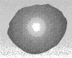
(3)由该测量系统对一个实际半径尺寸为R的标准球表面进行测量(实例中标准球的半径为25.0345mm),从一个视场采集即可获得其部分球面的三维数据(图8为实例中标准球的三维图,共134270个点)。(3) The measurement system measures the surface of a standard sphere with an actual radius of R (the radius of the standard sphere in the example is 25.0345 mm), and the three-dimensional data of a part of the sphere can be obtained from a field of view (Fig. 8 is The three-dimensional map of the standard ball in the example, a total of 134270 points).
(4)对获取的球面三维数据进行最小二乘拟合出球面方程,并计算拟合球的半径r(实例中拟合得到球的半径r为31.6998mm)。(4) Perform least squares fitting on the obtained spherical three-dimensional data to obtain the spherical equation, and calculate the radius r of the fitted sphere (in the example, the radius r of the sphere obtained by fitting is 31.6998 mm).
(5)计算尺度因子
(6)将所有摄影测量获得的标志点三维坐标Xk均乘以该尺度因子s作为校正后的标志点坐标X′k=s·Xk,k=1,2,Λ99。(6) Multiply the three-dimensional coordinates Xk of all the landmarks obtained by photogrammetry by the scale factor s as the corrected coordinates of the landmarks X′k =s·Xk , k=1, 2, Λ99.
可见,方式二不仅可以准确地校正标靶,同时还可将基于相位的测量系统进行准确标定。It can be seen that the second method can not only accurately calibrate the target, but also accurately calibrate the phase-based measurement system.
与传统采用二维影像测量仪逐个标志点测量相比,本方法只需一个数码相机即可对标靶上标志点的坐标进行校正,不仅减少了工作量和处理环节,而且降低了成本。其次,传统平面标靶制作要求标靶平面具有较高的平整度,而本方法对标靶平面的平整度不作要求,亦可大大降低制作成本。再者,由于本方法能方便、准确地对平面标靶进行校正,结合手工粘贴标志点的方法制作标靶,无需精密昂贵的加工工具,可极大地简化标靶的制作。Compared with the traditional two-dimensional image measuring instrument to measure the marker points one by one, this method only needs a digital camera to correct the coordinates of the marker points on the target, which not only reduces the workload and processing links, but also reduces the cost. Secondly, traditional planar target production requires the target plane to have high flatness, but this method does not require the flatness of the target plane, and can greatly reduce the production cost. Furthermore, since the method can conveniently and accurately calibrate the planar target, combined with the method of manually pasting the marking points to make the target, no sophisticated and expensive processing tools are needed, which can greatly simplify the production of the target.
本领域的普通技术人员可以理解,实现上述实施例方法中的全部或部分步骤可以通过程序来指令相关的硬件完成,该程序可以存储于一计算机可读取存储介质中,如ROM/RAM、磁盘、光盘等。Those of ordinary skill in the art can understand that all or part of the steps in the methods of the above-mentioned embodiments can be completed by instructing related hardware through a program, and the program can be stored in a computer-readable storage medium, such as ROM/RAM, disk , CD, etc.
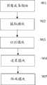
图9示出了本发明实施例提供的标靶校正系统的结构原理,为了便于描述,仅示出了与本发明实施例相关的部分。FIG. 9 shows the structural principle of the target calibration system provided by the embodiment of the present invention. For ease of description, only the parts related to the embodiment of the present invention are shown.
如图9所示,本发明实施例提供的标靶校正系统包括图像采集模块901、提取模块902、识别模块903、运算模块904和缩放模块905。其中图像采集模块901用于从不同角度获取标靶的多幅图像,所述标靶设有多个标志点;提取模块902用于分别提取各图像中标志点的中心作为特征点;识别模块903用于建立各幅图像间同名标志点的对应关系;运算模块904用于计算所述特征点的三维坐标,所述特征点的三维坐标由尺度因子所约束;缩放模块905用于获取所述尺度因子,将各特征点的三维坐标缩放至实际尺寸。As shown in FIG. 9 , the target calibration system provided by the embodiment of the present invention includes an
上述各个模块(单元)的工作原理如上文所述,此处不再加以赘述。The working principles of the above modules (units) are as described above, and will not be repeated here.
上述标靶校正系统的各个模块(单元)可以为软件单元、硬件单元或者软硬件结合的单元,软件单元部分可以存储于一计算机可读取存储介质中,如ROM/RAM、磁盘、光盘等。Each module (unit) of the above-mentioned target calibration system can be a software unit, a hardware unit, or a combination of software and hardware. The software unit can be stored in a computer-readable storage medium, such as ROM/RAM, magnetic disk, optical disk, etc.
本发明实施例先从不同角度拍摄标靶,获取多幅图像,分别提取各图像中标志点的中心作为特征点,建立各幅图像间同名标志点的对应关系,计算特征点的三维坐标,该特征点的三维坐标由尺度因子所约束,最后获取尺度因子,将各特征点的三维坐标缩放至实际尺寸,经本方法制作及校正的标靶具有较高的精度,操作简易,成本低。同时,采用条纹投影测量系统及标准球获取尺度因子,校正精度更高,其中相对精度(绝对精度/标靶尺寸)可达到1∶10000。此外,本方法可适用于从10mm至4m的各种尺寸及各种形状的标靶校正,并能够保持同样的相对精度,这是其他传统方法无法达到的。因而本方法和系统可广泛适用于视觉测量及系统标定。In the embodiment of the present invention, the target is first photographed from different angles, multiple images are obtained, the centers of the marker points in each image are respectively extracted as feature points, the corresponding relationship between the marker points with the same name is established in each image, and the three-dimensional coordinates of the feature points are calculated. The three-dimensional coordinates of the feature points are constrained by the scale factor. Finally, the scale factor is obtained, and the three-dimensional coordinates of each feature point are scaled to the actual size. The target made and calibrated by this method has high precision, easy operation, and low cost. At the same time, using the fringe projection measurement system and the standard sphere to obtain the scale factor, the calibration accuracy is higher, and the relative accuracy (absolute accuracy/target size) can reach 1:10000. In addition, the method can be applied to the calibration of targets of various sizes and shapes from 10mm to 4m, and can maintain the same relative accuracy, which cannot be achieved by other traditional methods. Therefore, the method and system can be widely used in visual measurement and system calibration.
以上所述仅为本发明的较佳实施例而已,并不用以限制本发明,凡在本发明的精神和原则之内所作的任何修改、等同替换和改进等,均应包含在本发明的保护范围之内。The above descriptions are only preferred embodiments of the present invention, and are not intended to limit the present invention. Any modifications, equivalent replacements and improvements made within the spirit and principles of the present invention should be included in the protection of the present invention. within range.
Claims (10)
Translated fromChinese


Priority Applications (1)
| Application Number | Priority Date | Filing Date | Title |
|---|---|---|---|
| CN201010580900.XACN102376089B (en) | 2010-12-09 | 2010-12-09 | Target correction method and system |
Applications Claiming Priority (1)
| Application Number | Priority Date | Filing Date | Title |
|---|---|---|---|
| CN201010580900.XACN102376089B (en) | 2010-12-09 | 2010-12-09 | Target correction method and system |
Publications (2)
| Publication Number | Publication Date |
|---|---|
| CN102376089Atrue CN102376089A (en) | 2012-03-14 |
| CN102376089B CN102376089B (en) | 2014-05-07 |
Family
ID=45794642
Family Applications (1)
| Application Number | Title | Priority Date | Filing Date |
|---|---|---|---|
| CN201010580900.XAActiveCN102376089B (en) | 2010-12-09 | 2010-12-09 | Target correction method and system |
Country Status (1)
| Country | Link |
|---|---|
| CN (1) | CN102376089B (en) |
Cited By (33)
| Publication number | Priority date | Publication date | Assignee | Title |
|---|---|---|---|---|
| CN102778199A (en)* | 2012-08-08 | 2012-11-14 | 苏州逸美德自动化科技有限公司 | Coordinate transformation method for nine-point correction of industrial camera |
| CN102915535A (en)* | 2012-08-23 | 2013-02-06 | 深圳大学 | Method and system for correcting circle center deviation of round mark points during camera projection transformation |
| CN103377469A (en)* | 2012-04-23 | 2013-10-30 | 宇龙计算机通信科技(深圳)有限公司 | Terminal and image processing method |
| CN103514450A (en)* | 2012-06-29 | 2014-01-15 | 华为技术有限公司 | Image feature extracting method and image correcting method and equipment |
| CN104754323A (en)* | 2013-12-31 | 2015-07-01 | 苏州智华汽车电子有限公司 | Calibration method of camera optical axis detection apparatus |
| CN104867160A (en)* | 2015-06-17 | 2015-08-26 | 合肥工业大学 | Directional calibration target for camera inner and outer parameter calibration |
| CN105423975A (en)* | 2016-01-12 | 2016-03-23 | 济南大学 | Calibration system and method of large-size workpiece |
| CN105643096A (en)* | 2016-03-28 | 2016-06-08 | 大族激光科技产业集团股份有限公司 | Target positioning method and device based on laser processing machine table and laser processing machine table |
| CN105678088A (en)* | 2016-01-12 | 2016-06-15 | 西安交通大学 | Balancing optimization algorithm for target measuring head |
| CN105825498A (en)* | 2015-01-27 | 2016-08-03 | 株式会社拓普康 | Survey data processing device, survey data processing method, and program therefor |
| CN106296646A (en)* | 2015-06-25 | 2017-01-04 | (株)凯希思 | The tolerance correcting unit of AVM system and method thereof |
| CN106595483A (en)* | 2016-12-19 | 2017-04-26 | 华中科技大学无锡研究院 | Active light hand-held target and cooperation mark point identification method thereof |
| CN107478155A (en)* | 2017-08-24 | 2017-12-15 | 苏州光照精密仪器有限公司 | Product inspection method, apparatus and system |
| CN107633533A (en)* | 2017-09-25 | 2018-01-26 | 深圳大学 | High precision cylindrical index point center positioning method and device under big distortion camera lens |
| CN107991665A (en)* | 2017-11-23 | 2018-05-04 | 江苏理工学院 | It is a kind of based on fixed-focus camera to target three-dimensional coordinate method for continuous measuring |
| CN108007472A (en)* | 2017-12-01 | 2018-05-08 | 深圳市沃特沃德股份有限公司 | Measure the method and system of vision sweeping robot odometer penalty coefficient |
| CN108680182A (en)* | 2017-12-01 | 2018-10-19 | 深圳市沃特沃德股份有限公司 | Measure the method and system of vision sweeping robot odometer penalty coefficient |
| CN109029382A (en)* | 2018-08-20 | 2018-12-18 | 上海矩尺土木科技有限公司 | A kind of screw retention early warning and monitoring device |
| CN109443214A (en)* | 2018-12-19 | 2019-03-08 | 广东工业大学 | A kind of scaling method of structured light three-dimensional vision, device and measurement method, device |
| WO2019051728A1 (en)* | 2017-09-14 | 2019-03-21 | 深圳大学 | Three-dimensional digital imaging method and device for wrapped phase based on phase mapping |
| CN109816724A (en)* | 2018-12-04 | 2019-05-28 | 中国科学院自动化研究所 | Method and device for 3D feature extraction based on machine vision |
| CN109916300A (en)* | 2019-03-20 | 2019-06-21 | 天远三维(天津)科技有限公司 | The index point towards 3-D scanning based on online image procossing pastes indicating means |
| CN110009692A (en)* | 2019-03-28 | 2019-07-12 | 渤海大学 | Large-scale control field artificial marker point for camera calibration and its coding method |
| CN110176035A (en)* | 2019-05-08 | 2019-08-27 | 深圳市易尚展示股份有限公司 | Localization method, device, computer equipment and the storage medium of index point |
| CN110533714A (en)* | 2019-08-21 | 2019-12-03 | 合肥晌玥科技有限公司 | Method and system based on image processing techniques detection target object maximum inscribed circle |
| CN111023995A (en)* | 2019-11-18 | 2020-04-17 | 西安电子科技大学 | A three-dimensional measurement method based on random two-frame phase-shift fringe pattern |
| CN112241988A (en)* | 2019-08-22 | 2021-01-19 | 北京新能源汽车技术创新中心有限公司 | Image processing method, image processing device, computer equipment and storage medium |
| CN113409438A (en)* | 2020-02-28 | 2021-09-17 | 华为技术有限公司 | Digital photogrammetry method, electronic equipment and system |
| CN114061472A (en)* | 2021-11-03 | 2022-02-18 | 常州市建筑科学研究院集团股份有限公司 | Method for correcting measurement coordinate error based on target |
| CN116007505A (en)* | 2022-12-15 | 2023-04-25 | 杭州鲁尔物联科技有限公司 | Monocular vision measurement target displacement correction method and device and computer equipment |
| CN117132653A (en)* | 2023-08-30 | 2023-11-28 | 中铁西南科学研究院有限公司 | Target-based machine vision displacement measurement method, system and equipment |
| CN118781206B (en)* | 2024-09-11 | 2024-12-06 | 中国人民解放军国防科技大学 | Visual navigation equipment reference calibration method based on collimator |
| CN116007505B (en)* | 2022-12-15 | 2025-10-17 | 杭州鲁尔物联科技有限公司 | Monocular vision measurement target displacement correction method and device and computer equipment |
Citations (2)
| Publication number | Priority date | Publication date | Assignee | Title |
|---|---|---|---|---|
| US20100079598A1 (en)* | 2008-09-03 | 2010-04-01 | University Of South Carolina | Robust Stereo Calibration System and Method for Accurate Digital Image Correlation Measurements |
| CN101727670A (en)* | 2009-11-10 | 2010-06-09 | 西安交通大学 | Flexible calibrating method and device for variable-format multiple-camera system |
- 2010
- 2010-12-09CNCN201010580900.XApatent/CN102376089B/enactiveActive
Patent Citations (2)
| Publication number | Priority date | Publication date | Assignee | Title |
|---|---|---|---|---|
| US20100079598A1 (en)* | 2008-09-03 | 2010-04-01 | University Of South Carolina | Robust Stereo Calibration System and Method for Accurate Digital Image Correlation Measurements |
| CN101727670A (en)* | 2009-11-10 | 2010-06-09 | 西安交通大学 | Flexible calibrating method and device for variable-format multiple-camera system |
Non-Patent Citations (3)
| Title |
|---|
| 刘晓利等: "借助标志点的深度数据全局匹配方法", 《光学学报》, vol. 29, no. 4, 30 April 2009 (2009-04-30), pages 1010 - 1014* |
| 刘炜刚等: "利用计算机自动识别和匹配标靶校正摄影镜头畸变", 《北京科技大学学报》, vol. 22, no. 6, 31 December 2000 (2000-12-31), pages 561 - 564* |
| 吴丽: "平面参数的几何光学测量及分析", 《中国优秀硕士学位论文全文数据库》, no. 3, 15 September 2007 (2007-09-15), pages 44 - 49* |
Cited By (47)
| Publication number | Priority date | Publication date | Assignee | Title |
|---|---|---|---|---|
| CN103377469A (en)* | 2012-04-23 | 2013-10-30 | 宇龙计算机通信科技(深圳)有限公司 | Terminal and image processing method |
| CN103514450B (en)* | 2012-06-29 | 2017-02-15 | 华为技术有限公司 | Image feature extracting method and image correcting method and equipment |
| CN103514450A (en)* | 2012-06-29 | 2014-01-15 | 华为技术有限公司 | Image feature extracting method and image correcting method and equipment |
| CN102778199B (en)* | 2012-08-08 | 2014-11-26 | 苏州逸美德自动化科技有限公司 | Coordinate transformation method for nine-point correction of industrial camera |
| CN102778199A (en)* | 2012-08-08 | 2012-11-14 | 苏州逸美德自动化科技有限公司 | Coordinate transformation method for nine-point correction of industrial camera |
| CN102915535A (en)* | 2012-08-23 | 2013-02-06 | 深圳大学 | Method and system for correcting circle center deviation of round mark points during camera projection transformation |
| CN102915535B (en)* | 2012-08-23 | 2016-01-20 | 深圳大学 | The circle center error modification method of circular index point and system in camera projection transformation |
| CN104754323A (en)* | 2013-12-31 | 2015-07-01 | 苏州智华汽车电子有限公司 | Calibration method of camera optical axis detection apparatus |
| CN105825498B (en)* | 2015-01-27 | 2021-10-19 | 株式会社拓普康 | Measurement data processing device, measurement data processing method, and program |
| CN105825498A (en)* | 2015-01-27 | 2016-08-03 | 株式会社拓普康 | Survey data processing device, survey data processing method, and program therefor |
| CN104867160A (en)* | 2015-06-17 | 2015-08-26 | 合肥工业大学 | Directional calibration target for camera inner and outer parameter calibration |
| CN104867160B (en)* | 2015-06-17 | 2017-11-07 | 合肥工业大学 | A kind of directionality demarcation target demarcated for camera interior and exterior parameter |
| CN106296646B (en)* | 2015-06-25 | 2019-01-08 | (株) 凯希思 | Tolerance means for correcting, method and its recording medium of AVM system |
| CN106296646A (en)* | 2015-06-25 | 2017-01-04 | (株)凯希思 | The tolerance correcting unit of AVM system and method thereof |
| CN105678088A (en)* | 2016-01-12 | 2016-06-15 | 西安交通大学 | Balancing optimization algorithm for target measuring head |
| CN105423975A (en)* | 2016-01-12 | 2016-03-23 | 济南大学 | Calibration system and method of large-size workpiece |
| CN105678088B (en)* | 2016-01-12 | 2019-01-18 | 西安交通大学 | A kind of adjustment optimization algorithm of target gauge head |
| CN105643096A (en)* | 2016-03-28 | 2016-06-08 | 大族激光科技产业集团股份有限公司 | Target positioning method and device based on laser processing machine table and laser processing machine table |
| CN106595483B (en)* | 2016-12-19 | 2019-03-01 | 华中科技大学无锡研究院 | A kind of active light hand-held target and its cooperation marker point identification method |
| CN106595483A (en)* | 2016-12-19 | 2017-04-26 | 华中科技大学无锡研究院 | Active light hand-held target and cooperation mark point identification method thereof |
| CN107478155A (en)* | 2017-08-24 | 2017-12-15 | 苏州光照精密仪器有限公司 | Product inspection method, apparatus and system |
| WO2019051728A1 (en)* | 2017-09-14 | 2019-03-21 | 深圳大学 | Three-dimensional digital imaging method and device for wrapped phase based on phase mapping |
| CN107633533A (en)* | 2017-09-25 | 2018-01-26 | 深圳大学 | High precision cylindrical index point center positioning method and device under big distortion camera lens |
| CN107633533B (en)* | 2017-09-25 | 2020-08-18 | 深圳大学 | High-precision circular marker point center positioning method and device under large distortion lens |
| CN107991665A (en)* | 2017-11-23 | 2018-05-04 | 江苏理工学院 | It is a kind of based on fixed-focus camera to target three-dimensional coordinate method for continuous measuring |
| CN108680182A (en)* | 2017-12-01 | 2018-10-19 | 深圳市沃特沃德股份有限公司 | Measure the method and system of vision sweeping robot odometer penalty coefficient |
| CN108007472A (en)* | 2017-12-01 | 2018-05-08 | 深圳市沃特沃德股份有限公司 | Measure the method and system of vision sweeping robot odometer penalty coefficient |
| CN109029382A (en)* | 2018-08-20 | 2018-12-18 | 上海矩尺土木科技有限公司 | A kind of screw retention early warning and monitoring device |
| CN109029382B (en)* | 2018-08-20 | 2023-08-08 | 上海矩尺土木科技有限公司 | Bolt looseness-prevention early warning monitoring device |
| CN109816724A (en)* | 2018-12-04 | 2019-05-28 | 中国科学院自动化研究所 | Method and device for 3D feature extraction based on machine vision |
| CN109816724B (en)* | 2018-12-04 | 2021-07-23 | 中国科学院自动化研究所 | Method and device for 3D feature extraction based on machine vision |
| CN109443214A (en)* | 2018-12-19 | 2019-03-08 | 广东工业大学 | A kind of scaling method of structured light three-dimensional vision, device and measurement method, device |
| CN109916300A (en)* | 2019-03-20 | 2019-06-21 | 天远三维(天津)科技有限公司 | The index point towards 3-D scanning based on online image procossing pastes indicating means |
| CN110009692A (en)* | 2019-03-28 | 2019-07-12 | 渤海大学 | Large-scale control field artificial marker point for camera calibration and its coding method |
| CN110176035A (en)* | 2019-05-08 | 2019-08-27 | 深圳市易尚展示股份有限公司 | Localization method, device, computer equipment and the storage medium of index point |
| CN110176035B (en)* | 2019-05-08 | 2021-09-28 | 深圳市易尚展示股份有限公司 | Method and device for positioning mark point, computer equipment and storage medium |
| CN110533714A (en)* | 2019-08-21 | 2019-12-03 | 合肥晌玥科技有限公司 | Method and system based on image processing techniques detection target object maximum inscribed circle |
| CN112241988B (en)* | 2019-08-22 | 2024-09-06 | 北京国家新能源汽车技术创新中心有限公司 | Image processing method, device, computer equipment and storage medium |
| CN112241988A (en)* | 2019-08-22 | 2021-01-19 | 北京新能源汽车技术创新中心有限公司 | Image processing method, image processing device, computer equipment and storage medium |
| CN111023995A (en)* | 2019-11-18 | 2020-04-17 | 西安电子科技大学 | A three-dimensional measurement method based on random two-frame phase-shift fringe pattern |
| CN113409438A (en)* | 2020-02-28 | 2021-09-17 | 华为技术有限公司 | Digital photogrammetry method, electronic equipment and system |
| CN114061472B (en)* | 2021-11-03 | 2024-03-19 | 常州市建筑科学研究院集团股份有限公司 | Method for correcting measurement coordinate error based on target |
| CN114061472A (en)* | 2021-11-03 | 2022-02-18 | 常州市建筑科学研究院集团股份有限公司 | Method for correcting measurement coordinate error based on target |
| CN116007505A (en)* | 2022-12-15 | 2023-04-25 | 杭州鲁尔物联科技有限公司 | Monocular vision measurement target displacement correction method and device and computer equipment |
| CN116007505B (en)* | 2022-12-15 | 2025-10-17 | 杭州鲁尔物联科技有限公司 | Monocular vision measurement target displacement correction method and device and computer equipment |
| CN117132653A (en)* | 2023-08-30 | 2023-11-28 | 中铁西南科学研究院有限公司 | Target-based machine vision displacement measurement method, system and equipment |
| CN118781206B (en)* | 2024-09-11 | 2024-12-06 | 中国人民解放军国防科技大学 | Visual navigation equipment reference calibration method based on collimator |
Also Published As
| Publication number | Publication date |
|---|---|
| CN102376089B (en) | 2014-05-07 |
Similar Documents
| Publication | Publication Date | Title |
|---|---|---|
| CN102376089A (en) | Target correction method and system | |
| CN105551039B (en) | The scaling method and device of structural light three-dimensional scanning system | |
| CN110068270B (en) | Monocular vision box volume measuring method based on multi-line structured light image recognition | |
| CN102364299B (en) | Calibration technology for multiple structured light projected three-dimensional profile measuring heads | |
| CN101727670B (en) | Flexible calibrating method and device for variable-format multiple-camera system | |
| CN103411553B (en) | The quick calibrating method of multi-linear structured light vision sensors | |
| CN104200086B (en) | Wide-baseline visible light camera pose estimation method | |
| CN109146980A (en) | The depth extraction and passive ranging method of optimization based on monocular vision | |
| CN110223355B (en) | Feature mark point matching method based on dual epipolar constraint | |
| CN103267491B (en) | The method and system of automatic acquisition complete three-dimensional data of object surface | |
| CN102654391B (en) | Stripe projection three-dimensional measurement system based on bundle adjustment principle and calibration method thereof | |
| CN100557634C (en) | A camera calibration method based on dual one-dimensional targets | |
| CN105931222B (en) | The method for realizing high-precision camera calibration with low precision two dimensional surface target | |
| CN107886547B (en) | Fisheye camera calibration method and system | |
| CN106990776B (en) | Robot homing positioning method and system | |
| CN104677277B (en) | A kind of method and system for measuring object geometric attribute or distance | |
| CN113538583B (en) | Accurate positioning method and vision system for position of workpiece on machine tool | |
| CN102155923A (en) | Splicing measuring method and system based on three-dimensional target | |
| CN102810205A (en) | Method for calibrating camera shooting or photographing device | |
| CN105574812B (en) | Multi-angle three-dimensional data method for registering and device | |
| CN111637851B (en) | Aruco code-based visual measurement method and device for plane rotation angle | |
| CN109272555B (en) | A method of obtaining and calibrating external parameters of RGB-D camera | |
| WO2023046211A1 (en) | Photogrammetry method, apparatus and device, and storage medium | |
| CN113888641B (en) | A method for measuring standing tree diameter at breast height based on machine vision and deep learning | |
| CN110763204A (en) | Planar coding target and pose measurement method thereof |
Legal Events
| Date | Code | Title | Description |
|---|---|---|---|
| C06 | Publication | ||
| PB01 | Publication | ||
| C10 | Entry into substantive examination | ||
| SE01 | Entry into force of request for substantive examination | ||
| C14 | Grant of patent or utility model | ||
| GR01 | Patent grant | ||
| C41 | Transfer of patent application or patent right or utility model | ||
| TR01 | Transfer of patent right | Effective date of registration:20170113 Address after:518000 Futian District, Shenzhen, Fu Qiang Road, No. 4001 (Shenzhen cultural and Creative Park) AB block, layer B301, three, Patentee after:Shenzhen Esun Display Co., Ltd. Address before:518060 Nanhai Road, Guangdong, Shenzhen, No. 3688, No. Patentee before:Shenzhen University | |
| CP02 | Change in the address of a patent holder | ||
| CP02 | Change in the address of a patent holder | Address after:518133 23rd floor, Yishang science and technology creative building, Jiaan South Road, Haiwang community Central District, Xin'an street, Bao'an District, Shenzhen City, Guangdong Province Patentee after:SHENZHEN ESUN DISPLAY Co.,Ltd. Address before:B301, 3rd floor, block AB, 4001 Fuqiang Road, Futian District, Shenzhen City, Guangdong Province Patentee before:SHENZHEN ESUN DISPLAY Co.,Ltd. |