CN102374652A - Fan assembly - Google Patents
Fan assemblyDownload PDFInfo
- Publication number
- CN102374652A CN102374652ACN2011102255139ACN201110225513ACN102374652ACN 102374652 ACN102374652 ACN 102374652ACN 2011102255139 ACN2011102255139 ACN 2011102255139ACN 201110225513 ACN201110225513 ACN 201110225513ACN 102374652 ACN102374652 ACN 102374652A
- Authority
- CN
- China
- Prior art keywords
- housing
- air
- fan assembly
- air outlet
- airflow
- Prior art date
- Legal status (The legal status is an assumption and is not a legal conclusion. Google has not performed a legal analysis and makes no representation as to the accuracy of the status listed.)
- Granted
Links
Images


Classifications
- F—MECHANICAL ENGINEERING; LIGHTING; HEATING; WEAPONS; BLASTING
- F04—POSITIVE - DISPLACEMENT MACHINES FOR LIQUIDS; PUMPS FOR LIQUIDS OR ELASTIC FLUIDS
- F04D—NON-POSITIVE-DISPLACEMENT PUMPS
- F04D25/00—Pumping installations or systems
- F04D25/02—Units comprising pumps and their driving means
- F04D25/08—Units comprising pumps and their driving means the working fluid being air, e.g. for ventilation
- F—MECHANICAL ENGINEERING; LIGHTING; HEATING; WEAPONS; BLASTING
- F24—HEATING; RANGES; VENTILATING
- F24F—AIR-CONDITIONING; AIR-HUMIDIFICATION; VENTILATION; USE OF AIR CURRENTS FOR SCREENING
- F24F7/00—Ventilation
- F24F7/007—Ventilation with forced flow
- F—MECHANICAL ENGINEERING; LIGHTING; HEATING; WEAPONS; BLASTING
- F04—POSITIVE - DISPLACEMENT MACHINES FOR LIQUIDS; PUMPS FOR LIQUIDS OR ELASTIC FLUIDS
- F04D—NON-POSITIVE-DISPLACEMENT PUMPS
- F04D15/00—Control, e.g. regulation, of pumps, pumping installations or systems
- F04D15/02—Stopping of pumps, or operating valves, on occurrence of unwanted conditions
- F04D15/0209—Stopping of pumps, or operating valves, on occurrence of unwanted conditions responsive to a condition of the working fluid
- F04D15/0218—Stopping of pumps, or operating valves, on occurrence of unwanted conditions responsive to a condition of the working fluid the condition being a liquid level or a lack of liquid supply
- F—MECHANICAL ENGINEERING; LIGHTING; HEATING; WEAPONS; BLASTING
- F04—POSITIVE - DISPLACEMENT MACHINES FOR LIQUIDS; PUMPS FOR LIQUIDS OR ELASTIC FLUIDS
- F04D—NON-POSITIVE-DISPLACEMENT PUMPS
- F04D29/00—Details, component parts, or accessories
- F04D29/40—Casings; Connections of working fluid
- F04D29/42—Casings; Connections of working fluid for radial or helico-centrifugal pumps
- F04D29/44—Fluid-guiding means, e.g. diffusers
- F—MECHANICAL ENGINEERING; LIGHTING; HEATING; WEAPONS; BLASTING
- F04—POSITIVE - DISPLACEMENT MACHINES FOR LIQUIDS; PUMPS FOR LIQUIDS OR ELASTIC FLUIDS
- F04F—PUMPING OF FLUID BY DIRECT CONTACT OF ANOTHER FLUID OR BY USING INERTIA OF FLUID TO BE PUMPED; SIPHONS
- F04F5/00—Jet pumps, i.e. devices in which flow is induced by pressure drop caused by velocity of another fluid flow
- F04F5/14—Jet pumps, i.e. devices in which flow is induced by pressure drop caused by velocity of another fluid flow the inducing fluid being elastic fluid
- F04F5/16—Jet pumps, i.e. devices in which flow is induced by pressure drop caused by velocity of another fluid flow the inducing fluid being elastic fluid displacing elastic fluids
- F—MECHANICAL ENGINEERING; LIGHTING; HEATING; WEAPONS; BLASTING
- F24—HEATING; RANGES; VENTILATING
- F24H—FLUID HEATERS, e.g. WATER OR AIR HEATERS, HAVING HEAT-GENERATING MEANS, e.g. HEAT PUMPS, IN GENERAL
- F24H3/00—Air heaters
- F24H3/02—Air heaters with forced circulation
- F24H3/04—Air heaters with forced circulation the air being in direct contact with the heating medium, e.g. electric heating element
- F24H3/0405—Air heaters with forced circulation the air being in direct contact with the heating medium, e.g. electric heating element using electric energy supply, e.g. the heating medium being a resistive element; Heating by direct contact, i.e. with resistive elements, electrodes and fins being bonded together without additional element in-between
- F24H3/0411—Air heaters with forced circulation the air being in direct contact with the heating medium, e.g. electric heating element using electric energy supply, e.g. the heating medium being a resistive element; Heating by direct contact, i.e. with resistive elements, electrodes and fins being bonded together without additional element in-between for domestic or space-heating systems
- F24H3/0417—Air heaters with forced circulation the air being in direct contact with the heating medium, e.g. electric heating element using electric energy supply, e.g. the heating medium being a resistive element; Heating by direct contact, i.e. with resistive elements, electrodes and fins being bonded together without additional element in-between for domestic or space-heating systems portable or mobile
- F—MECHANICAL ENGINEERING; LIGHTING; HEATING; WEAPONS; BLASTING
- F24—HEATING; RANGES; VENTILATING
- F24H—FLUID HEATERS, e.g. WATER OR AIR HEATERS, HAVING HEAT-GENERATING MEANS, e.g. HEAT PUMPS, IN GENERAL
- F24H3/00—Air heaters
- F24H3/12—Air heaters with additional heating arrangements
- F—MECHANICAL ENGINEERING; LIGHTING; HEATING; WEAPONS; BLASTING
- F24—HEATING; RANGES; VENTILATING
- F24F—AIR-CONDITIONING; AIR-HUMIDIFICATION; VENTILATION; USE OF AIR CURRENTS FOR SCREENING
- F24F13/00—Details common to, or for air-conditioning, air-humidification, ventilation or use of air currents for screening
- F24F13/02—Ducting arrangements
- F24F13/06—Outlets for directing or distributing air into rooms or spaces, e.g. ceiling air diffuser
- F—MECHANICAL ENGINEERING; LIGHTING; HEATING; WEAPONS; BLASTING
- F24—HEATING; RANGES; VENTILATING
- F24F—AIR-CONDITIONING; AIR-HUMIDIFICATION; VENTILATION; USE OF AIR CURRENTS FOR SCREENING
- F24F13/00—Details common to, or for air-conditioning, air-humidification, ventilation or use of air currents for screening
- F24F13/20—Casings or covers
- F24F2013/205—Mounting a ventilator fan therein
- F—MECHANICAL ENGINEERING; LIGHTING; HEATING; WEAPONS; BLASTING
- F24—HEATING; RANGES; VENTILATING
- F24F—AIR-CONDITIONING; AIR-HUMIDIFICATION; VENTILATION; USE OF AIR CURRENTS FOR SCREENING
- F24F2221/00—Details or features not otherwise provided for
- F24F2221/12—Details or features not otherwise provided for transportable
- F—MECHANICAL ENGINEERING; LIGHTING; HEATING; WEAPONS; BLASTING
- F24—HEATING; RANGES; VENTILATING
- F24F—AIR-CONDITIONING; AIR-HUMIDIFICATION; VENTILATION; USE OF AIR CURRENTS FOR SCREENING
- F24F2221/00—Details or features not otherwise provided for
- F24F2221/28—Details or features not otherwise provided for using the Coanda effect
- F—MECHANICAL ENGINEERING; LIGHTING; HEATING; WEAPONS; BLASTING
- F24—HEATING; RANGES; VENTILATING
- F24F—AIR-CONDITIONING; AIR-HUMIDIFICATION; VENTILATION; USE OF AIR CURRENTS FOR SCREENING
- F24F2221/00—Details or features not otherwise provided for
- F24F2221/34—Heater, e.g. gas burner, electric air heater
- F—MECHANICAL ENGINEERING; LIGHTING; HEATING; WEAPONS; BLASTING
- F24—HEATING; RANGES; VENTILATING
- F24H—FLUID HEATERS, e.g. WATER OR AIR HEATERS, HAVING HEAT-GENERATING MEANS, e.g. HEAT PUMPS, IN GENERAL
- F24H2250/00—Electrical heat generating means
- F24H2250/04—Positive temperature coefficients [PTC]; Negative temperature coefficients [NTC]
- F—MECHANICAL ENGINEERING; LIGHTING; HEATING; WEAPONS; BLASTING
- F24—HEATING; RANGES; VENTILATING
- F24H—FLUID HEATERS, e.g. WATER OR AIR HEATERS, HAVING HEAT-GENERATING MEANS, e.g. HEAT PUMPS, IN GENERAL
- F24H9/00—Details
- F24H9/0052—Details for air heaters
- F24H9/0057—Guiding means
- F24H9/0063—Guiding means in air channels
- F—MECHANICAL ENGINEERING; LIGHTING; HEATING; WEAPONS; BLASTING
- F24—HEATING; RANGES; VENTILATING
- F24H—FLUID HEATERS, e.g. WATER OR AIR HEATERS, HAVING HEAT-GENERATING MEANS, e.g. HEAT PUMPS, IN GENERAL
- F24H9/00—Details
- F24H9/18—Arrangement or mounting of grates or heating means
- F24H9/1854—Arrangement or mounting of grates or heating means for air heaters
- F24H9/1863—Arrangement or mounting of electric heating means
- F24H9/1872—PTC resistor
- Y—GENERAL TAGGING OF NEW TECHNOLOGICAL DEVELOPMENTS; GENERAL TAGGING OF CROSS-SECTIONAL TECHNOLOGIES SPANNING OVER SEVERAL SECTIONS OF THE IPC; TECHNICAL SUBJECTS COVERED BY FORMER USPC CROSS-REFERENCE ART COLLECTIONS [XRACs] AND DIGESTS
- Y10—TECHNICAL SUBJECTS COVERED BY FORMER USPC
- Y10T—TECHNICAL SUBJECTS COVERED BY FORMER US CLASSIFICATION
- Y10T137/00—Fluid handling
- Y10T137/6416—With heating or cooling of the system
- Y10T137/6525—Air heated or cooled [fan, fins, or channels]
- Y—GENERAL TAGGING OF NEW TECHNOLOGICAL DEVELOPMENTS; GENERAL TAGGING OF CROSS-SECTIONAL TECHNOLOGIES SPANNING OVER SEVERAL SECTIONS OF THE IPC; TECHNICAL SUBJECTS COVERED BY FORMER USPC CROSS-REFERENCE ART COLLECTIONS [XRACs] AND DIGESTS
- Y10—TECHNICAL SUBJECTS COVERED BY FORMER USPC
- Y10T—TECHNICAL SUBJECTS COVERED BY FORMER US CLASSIFICATION
- Y10T137/00—Fluid handling
- Y10T137/6416—With heating or cooling of the system
- Y10T137/6552—With diversion of part of fluid to heat or cool the device or its contents
Landscapes
- Engineering & Computer Science (AREA)
- Mechanical Engineering (AREA)
- General Engineering & Computer Science (AREA)
- Physics & Mathematics (AREA)
- Chemical & Material Sciences (AREA)
- Combustion & Propulsion (AREA)
- Thermal Sciences (AREA)
- Fluid Mechanics (AREA)
- Structures Of Non-Positive Displacement Pumps (AREA)
- Direct Air Heating By Heater Or Combustion Gas (AREA)
- Jet Pumps And Other Pumps (AREA)
Abstract
Translated fromChinese
Description
Translated fromChinese技术领域technical field
本发明涉及一种风扇组件。在优选实施例中,本发明涉及一种用于在住所,办公室或其他家庭环境中产生暖和气流的风扇式加热器。The invention relates to a fan assembly. In a preferred embodiment, the present invention relates to a fan heater for generating warm air flow in a dwelling, office or other domestic environment.
背景技术Background technique
传统的家用风扇一般包括安装为用于围绕轴线旋转的叶片组或翼片组,用于旋转叶片组以产生空气流的驱动装置。空气流的运动和循环产生了‘风冷’或微风,结果,使用者由于热量通过对流和蒸发被驱散而能感受到凉爽效果。Conventional domestic fans generally include a set of blades or vanes mounted for rotation about an axis, a drive means for rotating the set of blades to generate an air flow. The movement and circulation of the air stream creates a 'wind chill' or breeze and, as a result, the user experiences a cooling effect as heat is dissipated by convection and evaporation.
可以得到各种尺寸和形状的风扇。例如,吊扇直径可以为至少1m,且通常以悬吊于天花板上的方式安装,以提供向下的气流以及使房间降温。另一方面,台式风扇往往是直径约30厘米的,通常可以随意放置且可携带。落地式塔式风扇通常包括细长、竖直延伸的外壳,其约1米高,且罩着用于产生空气流的一个或多个旋转叶片组。使用摆动机构以旋转塔式风扇的出口以便空气流可以扫过房间的广阔的空间。Fans are available in a variety of sizes and shapes. For example, ceiling fans may be at least 1 m in diameter and are typically mounted suspended from the ceiling to provide downward airflow and cool the room. Desk fans, on the other hand, tend to be about 30 cm in diameter and are usually free to place and portable. A floor-standing tower fan typically includes an elongated, vertically extending housing, about 1 meter high, housing one or more sets of rotating blades for generating airflow. Use the swing mechanism to rotate the outlet of the tower fan so that the air flow can sweep across the wide spaces of the room.
风扇式加热器通常包括一些位于旋转叶片后面或前面的加热元件,使用户可以加热旋转叶片产生的空气流。加热元件通常为散热线圈或散热片的形式。可调节的恒温器(variable thermostat),或一些预定的输出功率设置,使用户能够控制从风扇式加热器发射的空气流的温度。Fan heaters typically include a number of heating elements located behind or in front of the rotating blades, allowing the user to heat the air stream created by the rotating blades. Heating elements are usually in the form of cooling coils or fins. An adjustable thermostat (variable thermostat), or some predetermined output power setting, enables the user to control the temperature of the air stream emitted from the fan heater.
这种配置类型的缺点是风扇式加热器的旋转叶片产生的空气流通常是不均衡的。这是由于跨叶片表面或跨风扇式加热器的面向外面的表面的变化。这些变化的程度可以从产品到产品甚至从一个单个的风扇式加热器到另一个而变化。这些变化导致湍流,或“波涛汹涌”的空气流的产生,该空气流可以被感觉为一系列的空气脉冲,这让用户感到不舒服。空气流的湍流导致的又一缺点是风扇式加热器的加热效果可以随距离迅速减弱。The disadvantage of this type of configuration is that the air flow created by the rotating blades of a fan heater is usually uneven. This is due to variations across the blade surface or across the outwardly facing surface of the fan heater. The extent of these variations can vary from product to product and even from one individual fan heater to another. These changes result in the creation of turbulent, or "choppy" airflow, which can be perceived as a series of air pulses, which is uncomfortable for the user. A further disadvantage caused by the turbulence of the air flow is that the heating effect of fan heaters can rapidly diminish with distance.
在家庭环境中,由于空间的限制,期望的是器具要尽可能小和尽可能紧凑。不期望的是器具的一部分向外突出或用户能够触摸任何运动部件,如叶片。风扇式加热器通常将叶片和散热线圈罩在笼子内的或带孔壳体内以防止用户通过接触移动的叶片或滚烫的散热线圈而受到伤害,但这种封闭的部分是很难清洗的。因此,在使用风扇式加热器期间,大量灰尘或其他碎屑可积聚在外壳内和散热线圈上。当散热线圈被激活,线圈的外表面的温度可迅速上升,尤其是当线圈的输出功率比较高时,其数值超过700℃。因此,在使用风扇式加热器期间,一些停在圈上的灰尘可被烧焦,导致在一些时候从风扇式加热器散发难闻的气味。In a domestic environment, due to space constraints, it is desirable that appliances be as small and compact as possible. It is not desirable for a part of the appliance to protrude outwards or for the user to be able to touch any moving parts such as blades. Fan heaters usually enclose the blades and cooling coils in a cage or perforated housing to prevent the user from being injured by touching the moving blades or hot cooling coils, but such enclosed parts are difficult to clean. Consequently, during use of the fan heater, large amounts of dust or other debris can accumulate within the housing and on the cooling coils. When the cooling coil is activated, the temperature of the outer surface of the coil can rise rapidly, especially when the output power of the coil is relatively high, and its value exceeds 700°C. Therefore, during the use of the fan heater, some of the dust settled on the ring may be burnt, causing an unpleasant smell to emanate from the fan heater at times.
我们的共同待决的专利申请PCT/GB2010/050272描述了一种风扇式加热器,该风扇式加热器不使用关在笼子里的叶片从风扇式加热器投射空气。相反,该风扇式加热器包括基部(该基部容纳用来抽吸主空气流进入基部的马达驱动的叶轮),和环形喷嘴,该环形喷嘴连接到基部,且包括环形嘴部,通过该嘴部从风扇发射出主空气流。喷嘴定义了中央开口,通过该中央开口风扇组件的局部环境中的空气被从嘴部发射的主空气流抽吸,放大主气流以产生气流。没有使用有叶片风扇从风扇式加热器投射气流,相对均衡的气流被产生并引导进入房间或朝向用户。在一个实施例中,加热器位于喷嘴内以在主空气流从嘴部发射前加热主空气流。通过将加热器容纳在喷嘴内,用户免受滚烫的加热器的外表面。Our co-pending patent application PCT/GB2010/050272 describes a fan heater that does not use caged blades to project air from the fan heater. Instead, the fan heater includes a base housing a motor-driven impeller for drawing the primary airflow into the base, and an annular nozzle connected to the base and including an annular mouth through which The main air flow is emitted from the fan. The nozzle defines a central opening through which air in the local environment of the fan assembly is drawn by the primary airflow emitted from the mouth, amplifying the primary airflow to create an airflow. Instead of using a bladed fan to project airflow from the fan heater, a relatively even airflow is generated and directed into the room or towards the user. In one embodiment, a heater is located within the nozzle to heat the primary airflow before it is emitted from the mouth. By housing the heater inside the nozzle, the user is protected from the scalding outer surface of the heater.
发明内容Contents of the invention
本发明的第一方面提供了一种风扇组件,包括:A first aspect of the invention provides a fan assembly comprising:
用于产生空气流的装置;means for generating air flow;
用于加热所述空气流的第一部分的装置;means for heating a first portion of said air stream;
用于分流所述空气流的第二部分远离加热装置的装置;及means for diverting a second portion of said air flow away from the heating means; and
壳体,包括用于发射空气流的第一部分穿过开口的至少一个第一空气出口,和用于发射空气流的第二部分穿过开口的至少一个第二空气出口;a housing comprising at least one first air outlet for emitting a first portion of the airflow through the opening, and at least one second air outlet for emitting a second portion of the airflow through the opening;
其中,至少一个第二空气出口被布置为引导空气流的第二部分的至少一部分到壳体的外表面上方。Wherein at least one second air outlet is arranged to direct at least a part of the second portion of the air flow over the outer surface of the housing.
因此,本发明提供了风扇组件,该风扇组件具有用于发射处于不同温度的空气的多个空气出口。一个或多个第一空气出口被提供用来发射相对热的空气,该相对热的空气被加热装置加热过,而一个或多个第二空气出口被提供用来发射相对冷的空气,该相对冷的空气绕过加热装置。Accordingly, the present invention provides a fan assembly having multiple air outlets for emitting air at different temperatures. One or more first air outlets are provided to emit relatively hot air that has been heated by the heating means, and one or more second air outlets are provided to emit relatively cooler air that is relatively Cool air bypasses the heating unit.
由此存在于风扇组件内的不同的空气路径可被用户选择性地打开和关闭以改变从风扇组件中发射出来的空气流的温度度。风扇组件可包括阀门,遮板或其他装置,用于选择性地关闭空气路径之一,以使所有空气流通过第一空气出口或第二空气出口离开风扇组件。例如,遮板可以是在壳体的外表面上可滑动的或以其他方式可移动的,以选择性关闭第一空气出口或第二空气出口,从而迫使空气流通过加热装置或绕过加热装置。这可以使用户可迅速改变从壳体发射的空气流的温度。The different air paths thus present within the fan assembly can be selectively opened and closed by the user to vary the temperature of the air flow emitted from the fan assembly. The fan assembly may include a valve, shutter or other means for selectively closing one of the air paths so that all airflow exits the fan assembly through either the first air outlet or the second air outlet. For example, the shutter may be slidable or otherwise movable on the outer surface of the housing to selectively close the first air outlet or the second air outlet to force air flow through or around the heating means . This may allow the user to quickly change the temperature of the air stream emitted from the housing.
替代地或附加地,壳体可被布置为同时发射空气流的第一和第二部分。Alternatively or additionally, the housing may be arranged to emit the first and second portions of the air flow simultaneously.
如上所述,至少一个第二空气出口被布置为引导空气流的第二部分的至少一部分到壳体的外表面上方。在使用风扇组件中,这可以保持喷嘴的外表面凉爽。当壳体包括多个第二空气出口时,第二空气出口可以被布置为引导空气流的大致全部第二部分到壳体的至少一个外表面上方。第二空气出口可以被布置为引导空气流的第二部分到壳体的共同的外表面上方,或壳体的多个外表面上方,如壳体的前或后表面。As mentioned above, the at least one second air outlet is arranged to direct at least a part of the second portion of the air flow over the outer surface of the housing. In using a fan assembly, this keeps the outer surface of the nozzle cool. When the housing comprises a plurality of second air outlets, the second air outlets may be arranged to direct substantially all of the second portion of the air flow over at least one outer surface of the housing. The second air outlet may be arranged to direct a second portion of the airflow over a common outer surface of the housing, or over multiple outer surfaces of the housing, such as a front or rear surface of the housing.
优选该或每个第一空气出口被布置为引导空气流的第一部分到空气流的第二部分上方,使的相对凉爽的空气流的第二部被夹在相对热的空气流的第一部分和壳体的外表面之间,从而在相对热的空气流的第一部分和壳体的外表面之间提供了隔热层。Preferably the or each first air outlet is arranged to direct a first portion of the airflow over a second portion of the airflow such that the relatively cool second portion of the airflow is sandwiched between the relatively warm first portion of the airflow and An insulating layer is provided between the outer surfaces of the housing, thereby providing insulation between the first portion of the relatively hot air flow and the outer surfaces of the housing.
壳体优选地为环形壳体的形式,其优选地限定开口,来自壳体外部的空气被从空气出口发射的空气流抽吸通过该开口。第二空气出口可以被布置为引导空气流到壳体的外表面(其远离开口)上方。例如,当壳体是环形形状,第二空气出口之一可被布置为引导空气流的一部分到壳体的内部环形部分的外表面上方,使从该第二空气出口发射的空气流的该部分穿过开口,然而第二空气出口的另一个可以布置为引导空气流的另一部分到壳体的外部环形部分的外表面上方。然而,所有的第一和第二空气出口优选地被布置为发射空气流穿过开口以便于通过壳体外部空气的夹带最大化从壳体发射的空气流的放大。The housing is preferably in the form of an annular housing which preferably defines an opening through which air from outside the housing is drawn by the air flow emitted from the air outlet. The second air outlet may be arranged to direct air flow over an outer surface of the housing which is remote from the opening. For example, when the housing is annular in shape, one of the second air outlets may be arranged to direct a portion of the air flow over the outer surface of the inner annular portion of the housing such that the portion of the air flow emitted from the second air outlet Through the opening, however another one of the second air outlets may be arranged to direct another part of the air flow over the outer surface of the outer annular part of the housing. However, all of the first and second air outlets are preferably arranged to emit airflow through the opening to facilitate entrainment of air outside the housing by maximizing the amplification of the airflow emitted from the housing.
在第二方面,本发明提供了一种风扇组件,包括:In a second aspect, the present invention provides a fan assembly comprising:
用于产生空气流的装置;means for generating air flow;
用于加热所述空气流的第一部分的装置;means for heating a first portion of said air stream;
用于分流所述空气流的第二部分远离加热装置的装置;及means for diverting a second portion of said air flow away from the heating means; and
壳体,包括用于从壳体发射空气流的多个空气出口,壳体具有限定开口的环形外表面,壳体外的空气被从空气出口发射的空气流抽吸穿过该开口;a housing comprising a plurality of air outlets for emitting airflow from the housing, the housing having an annular outer surface defining an opening through which air outside the housing is drawn by the airflow emitted from the air outlets;
其中,所述多个空气出口包括用于发射空气流的第一部分穿过开口的至少一个第一空气出口,和用于发射空气流的第二部分穿过开口的至少一个第二空气出口;wherein said plurality of air outlets comprises at least one first air outlet for emitting a first portion of the air flow through the opening, and at least one second air outlet for emitting a second portion of the air flow through the opening;
其中,所述的至少一个第二空气出口被布置为引导空气流的第二部分到所述壳体的外表面上方,且所述的至少一个第一空气出口被布置为引导空气流的第一部分到空气流的第二部分上方。wherein said at least one second air outlet is arranged to direct a second portion of the air flow over the outer surface of said housing, and said at least one first air outlet is arranged to direct a first portion of the air flow to the second part of the air stream.
除了引导从一个或多个第二空气出口发射的空气流到壳体的外表面上方,在使用风扇组件时,壳体可被布置为传输空气流的第二部分到至少一个壳体的内表面上方或沿着至少一个壳体的内表面以保持该表面相对凉爽。替代地,分流装置被布置为分流空气流的第二部分和第三部分两者远离加热装置,且内部通道可被布置为沿着壳体的第一内表面,例如壳体的内部环形部分的内表面传输空气流的第二部分,并沿着壳体的第二内表面,例如壳体的外部环形部分的内表面传输空气流的第三部分。In addition to directing the air flow emitted from the one or more second air outlets over the outer surface of the housing, when using the fan assembly, the housing may be arranged to deliver a second portion of the air flow to at least one inner surface of the housing over or along at least one interior surface of the housing to keep that surface relatively cool. Alternatively, the diverter means is arranged to divert both the second part and the third part of the air flow away from the heating means, and the internal channel may be arranged along a first inner surface of the housing, for example of an inner annular part of the housing. The inner surface conveys the second portion of the airflow and conveys the third portion of the airflow along a second inner surface of the housing, such as the inner surface of the outer annular portion of the housing.
在这种情况下,可能发现,根据空气流的第一部分的温度,无需独立于空气流的第一部分,散发空气流的第二和第三部分两者穿过单独的空气出口,就可以提供壳体的外表面的充分凉爽。例如,空气流的第一和第三部分可在加热装置的下游,而空气流的第二部分可以被引导到内部环形壳体的外表面上方。In this case, it may be found that, depending on the temperature of the first portion of the air stream, it is possible to provide the enclosure without distributing both the second and third portions of the air stream through separate air outlets independently of the first portion of the air stream. Sufficient cooling of the outer surface of the body. For example, the first and third portions of the airflow may be downstream of the heating means, while the second portion of the airflow may be directed above the outer surface of the inner annular housing.
分流装置可包括用于分流空气流的第二部分远离加热装置的至少一个挡板,壁或其他表面。分流装置可与壳体部分中的一个一体形成或连接到其中一个壳体部分。分流装置可方便地形成机架的一部分,或连接到机架,该机架用于保持加热装置。分流装置在布置为分流空气流的的第二部分和空气流的第三部分两者远离加热装置的情形下,分流装置可包括机架的两个相互间隔开的部分。The diverting means may comprise at least one baffle, wall or other surface for diverting the second portion of the air flow away from the heating means. The flow diverting device may be integrally formed with or connected to one of the housing parts. The diverter means may conveniently form part of, or be attached to, a rack which is used to hold the heating means. The diverting means In case the diverting means are arranged to divert both the second part of the air flow and the third part of the air flow remote from the heating means, the diverting means may comprise two parts of the housing which are spaced apart from each other.
壳体优选包括用于传输空气流的第一部分到第一空气出口的第一通道装置,和用于传输空气流的第二部分到第二空气出口的第二通道装置,和用于从第二通道装置分隔第一通道装置的装置。分隔装置可与用于分流空气流的第二部分远离加热装置的分流装置一体形成,因此可包括机架的至少一个侧壁以保持加热装置。这样可以减少风扇组件的独立部件的数量。壳体还可包括第三通道装置,用于传输空气流的第三部分远离加热装置,优选沿着壳体的内表面。第二通道装置还可被布置为沿着壳体的内表面传输空气流的第二部分。The housing preferably comprises first passage means for conveying a first portion of the airflow to the first air outlet, and second passage means for conveying a second portion of the airflow to the second air outlet, and for passage from the second The channel means separates the means of the first channel means. The dividing means may be integrally formed with the diverting means for diverting the second portion of the air flow away from the heating means and may thus comprise at least one side wall of the housing to hold the heating means. This reduces the number of separate parts of the fan assembly. The housing may also comprise third channel means for conveying a third portion of the air flow away from the heating means, preferably along the inner surface of the housing. The second channel means may also be arranged to convey a second portion of the air flow along the inner surface of the housing.
机架可包括第一和第二侧壁,第一和第二侧壁被构造以保持加热组件在其间。第一和第二壁可形成第一通道于其间,其中包括的加热装置,该第一通道用于传输气流到壳体的第一空气出口。第一侧壁和壳体的第一内表面可形成第二通道,用于传输气流的第二部分沿着第一内表面到壳体的第二空气出口。第二侧壁和壳体的第二内表面,可选择性地形成第三通道,用于沿着第二内表面运输气流的第三部分。第三通道可与第一或第二通道合并,或它可输送空气流的第三部分到壳体的空气出口。The frame may include first and second side walls configured to hold the heating assembly therebetween. The first and second walls may form a first passage therebetween, including heating means, the first passage for delivering airflow to the first air outlet of the housing. The first side wall and the first inner surface of the housing may form a second channel for conveying a second portion of the airflow along the first inner surface to a second air outlet of the housing. The second side wall and the second inner surface of the housing optionally form a third channel for transporting a third portion of the airflow along the second inner surface. The third channel may merge with the first or second channel, or it may deliver a third portion of the air flow to the air outlet of the housing.
如上所述,壳体可包括内部环形壳体部分和外部环形壳体部分,它们在其间限定了用于接收空气流的内部通道,且分隔装置可位于壳体部分之间。每个壳体部分优选由相应的环形构件形成,但每个壳体部分可由多个构件连接在一起提供或以其他方式组装形成壳体部分。内部壳体部分和外部壳体部分可由塑料材料或由具有相对较低的热传导率(小于1Wm-1K-1)的其他材料形成,以防止壳体的外表面在风扇组件使用的过程中变得过热。As mentioned above, the housing may comprise an inner annular housing portion and an outer annular housing portion defining therebetween an internal passage for receiving the airflow, and the separation means may be located between the housing portions. Each housing part is preferably formed from a respective annular member, but each housing part may be provided from a plurality of members joined together or otherwise assembled to form the housing part. The inner and outer housing portions may be formed from a plastic material or from other materials having a relatively low thermal conductivity (less than 1 Wm−1 K−1 ) to prevent the outer surface of the housing from deteriorating during use of the fan assembly. Get overheated.
分隔装置也可限定壳体的第一空气出口和/或第二空气出口的一部分。例如,第一空气出口可位于外部壳体部分的内部表面和分隔装置之间。替代或附加地,所述至少一个第二空气出口可位于内部壳体部分的外表面和分隔装置之间。分隔装置包括用于将第二通道与第一通道分隔的壁的情况下,第一空气出口可位于外部壳体部分的内表面和壁的第一侧表面之间,和第二空气出口可位于内部壳体部分的外表面和壁的第二侧表面之间。The partition means may also define a part of the first air outlet and/or the second air outlet of the housing. For example, the first air outlet may be located between the inner surface of the outer housing part and the separation means. Alternatively or additionally, the at least one second air outlet may be located between the outer surface of the inner housing part and the separating means. Where the partition means comprises a wall for separating the second channel from the first channel, the first air outlet may be located between the inner surface of the outer housing part and the first side surface of the wall, and the second air outlet may be located Between the outer surface of the inner housing portion and the second side surface of the wall.
分隔装置可包括用于接合内部壳体部分和外部壳体部分中的一个的多个间隔件。这样可使第二通道装置和第三通道装置的至少一个的宽度通过在间隔件和上述内部壳体部分和外部壳体部分中至少一个之间的接合而沿通道的长度受到控制。The divider means may comprise a plurality of spacers for engaging one of the inner housing part and the outer housing part. This enables the width of at least one of the second and third channel means to be controlled along the length of the channel by engagement between the spacer and at least one of said inner and outer housing parts.
从空气出口发射空气的方向优选与空气流穿过内部通道的至少一部分的方向成大致直角。空气流优选沿大致的竖直方向穿过内部通道的至少一部分,且从空气出口发射的空气沿大致水平方向。内部通道优选位于喷嘴的前部,而空气出口优选位于壳体的后部,并被布置为引导空气朝向壳体的前方,并穿过开口。因此,每个第一和第二通道装置可被成形从而大致使空气流的相应部分的流动方向反向。The direction in which air is emitted from the air outlet is preferably substantially at right angles to the direction in which air flows through at least a portion of the inner channel. Air flow is preferably in a generally vertical direction through at least a portion of the interior passageway, and air emitted from the air outlet is in a generally horizontal direction. The internal passage is preferably at the front of the nozzle, while the air outlet is preferably at the rear of the housing and is arranged to direct air towards the front of the housing and through the opening. Accordingly, each first and second channel means may be shaped so as to substantially reverse the direction of flow of a corresponding portion of the airflow.
内部通道优选是环形的,且优选成形以将空气流分成两股气流,其绕开口沿相反方向流动。在这种情况下,加热装置优选被布置以加热每股气流的第一部分,且分流装置被布置以分流每股气流的第二部分远离加热装置。这些气流的第一部分可从壳体的公用第一空气出口发射。例如,单个第一空气出口可绕壳体的开口延伸。替代地,每股气流的第一部分可从壳体的相应的空气出口发射,并共同构成空气流的第一部分。这些第一空气出口可位于开口的相对侧上。The inner passage is preferably annular and is preferably shaped to split the air flow into two air streams which flow in opposite directions about the opening. In this case, the heating means are preferably arranged to heat the first part of each gas flow and the diverting means are arranged to divert the second part of each gas flow away from the heating means. A first portion of these airflows may be emitted from a common first air outlet of the housing. For example, a single first air outlet may extend around the opening of the housing. Alternatively, the first portion of each airflow may be emitted from a respective air outlet of the housing and together constitute the first portion of the airflow. These first air outlets may be located on opposite sides of the opening.
同样的,两股气流的第二部分可从壳体的公用第二空气出口发射。同样,单个第二空气出口可绕壳体的开口延伸。替代地,每股气流的第二部分可从壳体的相应的第二空气出口发射,并共同构成空气流的第二部分。同样,该些第二空气出口可位于开口的相对侧上。Likewise, the second portion of the two air streams may be emitted from a common second air outlet of the housing. Likewise, a single second air outlet may extend around the opening of the housing. Alternatively, the second portion of each airflow may be emitted from a respective second air outlet of the housing and together constitute the second portion of the airflow. Likewise, the second air outlets may be located on opposite sides of the opening.
加热装置的至少一部分可布置在壳体中。该加热装置可在开口周围延伸。其中,壳体限定圆形开口,加热装置优选地绕开口延伸至少270°,更优选绕开口延伸至少300°。在壳体定义了细长的开口的情形中,即,开口的高度大于其宽度,加热装置优选至少位于开口的相对侧上。At least a part of the heating device may be arranged in the housing. The heating means can extend around the opening. Where the housing defines a circular opening, the heating means preferably extends at least 270° around the opening, more preferably at least 300° around the opening. In case the housing defines an elongated opening, ie the height of the opening is greater than its width, the heating means are preferably located at least on opposite sides of the opening.
加热装置可包括位于内部通道内的至少一个陶瓷加热器。陶瓷加热器可以是多孔的,使空气流的第一部分在从一个或多个第一空气出口发射前穿过加热装置内的孔眼。加热器可由PTC(正温度系数)陶瓷材料(其在激活时能够迅速加热空气流)形成。The heating means may comprise at least one ceramic heater located within the inner channel. The ceramic heater may be porous such that the first portion of the air flow passes through apertures in the heating device before being emitted from the one or more first air outlets. The heater may be formed from a PTC (Positive Temperature Coefficient) ceramic material capable of rapidly heating the air flow when activated.
陶瓷材料可至少部分涂有金属材料或其他导电材料,以便于加热装置到风扇组件内的用于激活加热器的控制器的连接。替代地,至少一个无孔,优选陶瓷,加热器可被安装在位于内部通道内的金属框架内,并可连接到风扇组件的控制器。金属框架优选包括多个片以提供更大的表面面积,从而更好地热传导到空气流,同时还提供了电连接到加热装置的装置。The ceramic material may be at least partially coated with a metallic material or other conductive material to facilitate connection of the heating device to a controller within the fan assembly for activating the heater. Alternatively, at least one non-porous, preferably ceramic, heater may be mounted within a metal frame located within the internal channel and may be connected to the controller of the fan assembly. The metal frame preferably comprises multiple pieces to provide greater surface area for better heat transfer to the air flow, while also providing means for electrical connection to the heating means.
加热装置优选包括至少一个加热器组件。在空气流被分成两股气流的情形中,加热装置优选包括多个加热器组件,每个加热器组件用于加热相应气流的第一部分,和分流装置优选包括多个壁,每个壁用于分流相应气流的第二部分远离加热器组件。The heating means preferably comprises at least one heater assembly. Where the air stream is split into two air streams, the heating means preferably includes a plurality of heater assemblies, each for heating a first portion of the respective air stream, and the splitter means preferably includes a plurality of walls, each for A second portion of the corresponding gas flow is diverted away from the heater assembly.
每个空气出口优选为槽的形式,其优选宽度范围在0.5至5mm。第一空气出口的宽度优选与第二空气出口不同。在优选实施例中,第一空气出口的宽度大于第二空气出口的宽度,使大部分主空气流穿过加热装置。Each air outlet is preferably in the form of a slot, preferably having a width in the range of 0.5 to 5mm. The width of the first air outlet is preferably different from that of the second air outlet. In a preferred embodiment, the width of the first air outlet is greater than the width of the second air outlet such that a majority of the primary air flow passes through the heating means.
壳体的外表面,空气出口被布置为引导从其发射的空气流到该表面上方,优选是弯曲表面,更优选是柯恩达表面。壳体的内部壳体部分的外表面优选被成形以限定柯恩达表面。柯恩达表面是已知类型的表面,离开接近该表面的输出口的流体流在该表面上展现出科恩达效应。流体倾向于紧贴该表面上方流动,几乎是“粘在”或“拥抱”该表面。柯恩达效应是已经证明,有据可查的夹带方法,其中,主空气流被引导到柯恩达表面上方。柯恩达表面的特征的描述,在柯恩达表面上方的流体流的效应,可在诸如Reba,Scientific American,第214卷,1966年6月,第84到92页的文献中找到。通过柯恩达表面的使用,来自风扇组件外的增加量的空气被从空气出口发射的空气抽吸穿过开口。The outer surface of the housing, preferably a curved surface, more preferably a Coanda surface, over which the air outlet is arranged to direct the air flow emitted therefrom. The outer surface of the inner housing part of the housing is preferably shaped to define a Coanda surface. A Coanda surface is a known type of surface on which a fluid flow leaving an outlet close to the surface exhibits the Coanda effect. Fluids tend to flow just above the surface, almost "sticking" or "hugging" the surface. The Coanda effect is a proven, well-documented method of entrainment in which the primary air flow is directed above the Coanda surface. Descriptions of the characteristics of Coanda surfaces, the effects of fluid flow over Coanda surfaces, can be found in documents such as Reba, Scientific American, Vol. 214, June 1966, pp. 84-92. Through the use of the Coanda surface, an increased amount of air from outside the fan assembly is drawn through the opening by the air emitted from the air outlet.
在优选的实施例中,气流通过风扇组件的壳体产生。在下面的描述中,该空气流被称为主空气流。主空气流从壳体的空气出口发射,优选在柯恩达表面上方经过。主空气流夹带壳体周围的空气,其用作空气放大器,以将主空气流和夹带的空气两者供应给用户。夹带的空气将在这里被称为次空气流。次空气流是来自壳体的嘴部周围的房间的空间,区域或外部环境,通过置换,来自风扇组件周围的其他区域,并主要穿过由壳体定义的开口。被引导到柯恩达表面上方的主空气流结合夹带的次空气流,相当于从壳体定义的开口向前发射或投射的总空气流。In a preferred embodiment, airflow is generated through the housing of the fan assembly. In the following description, this air flow is referred to as the main air flow. The primary air flow is emitted from the air outlet of the housing, preferably passing over the Coanda surface. The primary air flow entrains air around the housing, which acts as an air amplifier to supply both the primary air flow and the entrained air to the user. The entrained air will be referred to herein as the secondary air flow. The secondary air flow is from the space, area or external environment of the room around the mouth of the housing, by displacement, from other areas around the fan assembly, and primarily through the opening defined by the housing. The primary air flow directed over the Coanda surface combined with the entrained secondary air flow corresponds to the total air flow projected or projected forward from the opening defined by the shell.
壳体优选包括位于柯恩达表面下游的扩散表面。扩散表面引导朝向用户的位置发射的空气流,同时保持平稳,均匀的输出。壳体的内部壳体部分的外表面优选被成形以定义扩散表面。该外表面优选包括位于扩散表面下游的引导表面,该引导表面相对于扩散表面向内倾斜。引导部分可以是圆柱形的,或可以相对于相对于外表面所绕的轴线向内或向外成锥形。向外成锥形的表面可以设置在引导部分下游。The housing preferably comprises a diffusing surface downstream of the Coanda surface. The diffuser surface directs the airflow emitted towards the user's position while maintaining a smooth, even output. The outer surface of the inner housing part of the housing is preferably shaped to define a diffusion surface. The outer surface preferably includes a guide surface downstream of the diffusing surface, which guide surface is inclined inwardly relative to the diffusing surface. The guide portion may be cylindrical, or may taper inwardly or outwardly relative to an axis about which the outer surface is about. An outwardly tapering surface may be provided downstream of the guide portion.
风扇组件优选还包括容纳所述用于产生空气流的装置的基座,且壳体连接到基座。该基座优选为大致圆柱形,且包括多个空气进口,空气流通过该空气进口进入风扇组件。The fan assembly preferably also includes a base housing said means for generating air flow, and the housing is connected to the base. The base is preferably generally cylindrical and includes a plurality of air inlets through which air flows into the fan assembly.
产生穿过壳体的空气流的装置优选包括马达驱动的叶轮。这可以提供风扇组件有效的空气流产生。产生空气流的装置优选包括直流无刷电机。这样可避免摩擦损失和在传统的有刷马达中使用的刷子中碳屑。在干净的或污染物敏感的环境中,比如医院或那些过敏症周围,减少的碳屑和排放物是有利的。尽管一般都使用在带叶片风扇中的感应马达也没有刷子,直流无刷电机可以提供比感应马达大得多的范围的运转速度。The means for generating air flow through the housing preferably comprises a motor driven impeller. This can provide efficient airflow generation by the fan assembly. The means for generating the air flow preferably comprise a DC brushless motor. This avoids friction loss and carbon dust in the brushes used in conventional brushed motors. In clean or pollutant sensitive environments, such as around hospitals or those with allergies, the reduced carbon dust and emissions are beneficial. Although the induction motors commonly used in bladed fans also have no brushes, brushless DC motors can provide a much wider range of operating speeds than induction motors.
加热装置优选定位在壳体中。分流装置也可以定位在壳体中。The heating device is preferably positioned in the housing. A shunt device may also be located in the housing.
然而,加热装置不必要位于壳体内。例如,加热装置和分流装置都可位于基座内,且布置壳体接收来自基座的相对热的空气流的第一部分和相对冷的空气流的第二部分,并运输空气流的第一部分到第一空气出口和空气流的第二部分到第二空气出口。壳体可包括用于限定第一通道装置和第二通道装置的内壁或挡板。However, it is not necessary that the heating means be located within the housing. For example, both the heating means and the flow diverting means may be located within the base, and the housing is arranged to receive a first portion of the relatively warm air flow and a second portion of the relatively cool air flow from the base, and transport the first portion of the air flow to The first air outlet and the second portion of the air flow to the second air outlet. The housing may comprise inner walls or baffles for defining the first channel means and the second channel means.
替代地,加热装置可位于壳体中,但分流装置可位于基座。在这种情况下,第二通道装置可被布置为简单的传输来自基座的空气流的第二部分到至少一个第二空气出口的同时,第一通道装置可布置为传输来自基座的空气流的第一部分运输到至少一个第一空气出口并容纳用于加热空气流的第一部分的加热装置。Alternatively, the heating means may be located in the housing, but the flow diverting means may be located in the base. In this case, the second channel means may be arranged to simply deliver a second portion of the air flow from the base to the at least one second air outlet while the first channel means may be arranged to deliver air from the base The first portion of the flow is conveyed to at least one first air outlet and accommodates heating means for heating the first portion of the air flow.
风扇组件优选为便携式风扇式加热器的形式。The fan assembly is preferably in the form of a portable fan heater.
上述与本发明的第一方面相关的特征描述同样适用于本发明的第二方面,反之亦然。The above descriptions of features related to the first aspect of the present invention are also applicable to the second aspect of the present invention, and vice versa.
附图说明Description of drawings
现在将参考附图仅通过举例的方式描述本发明的实施例,在附图中:Embodiments of the invention will now be described, by way of example only, with reference to the accompanying drawings, in which:
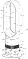
图1是从上方观察,风扇组件的前透视图;Figure 1 is a front perspective view of the fan assembly, viewed from above;
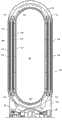
图2是风扇组件的前视图;Figure 2 is a front view of the fan assembly;
图3是沿图2的线B-B截取的剖面图;Fig. 3 is a sectional view taken along the line B-B of Fig. 2;
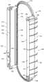
图4是风扇组件的喷嘴的分解图;Figure 4 is an exploded view of the nozzle of the fan assembly;
图5是喷嘴的加热器机架的前透视图;Figure 5 is a front perspective view of the heater housing of the nozzle;
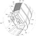
图6是从下方观察,连接到喷嘴的内部壳体部分的加热器机架的前透视图;Figure 6 is a front perspective view of the heater housing attached to the inner housing portion of the nozzle, viewed from below;
图7是图6中显示的区域X的近视图;Figure 7 is a close up view of the area X shown in Figure 6;
图8是图1中显示的区域Y的近视图;Figure 8 is a close up view of area Y shown in Figure 1;
图9是沿图2的线A-A截取的剖面图;Fig. 9 is a sectional view taken along line A-A of Fig. 2;
图10是图9中显示的区域Z的近视图;Figure 10 is a close up view of the area Z shown in Figure 9;
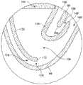
图11是沿图9的线C-C截取的喷嘴的剖面图;及Figure 11 is a cross-sectional view of the nozzle taken along line C-C of Figure 9; and
图12是风扇组件的控制系统的示意性图示。Figure 12 is a schematic illustration of a control system for a fan assembly.
具体实施方式Detailed ways
图1和图2示出了风扇组件10的外视图。风扇组件10是便携式风扇式加热器的形式。风扇组件10包括带空气进口14的本体12和喷嘴16,通过该空气进口14主空气流进入风扇组件10,喷嘴16为安装在本体12上的环形壳体的形式,该喷嘴16包括用于从风扇组件10发射主空气流的至少一个空气出口18。1 and 2 show external views of the
本体12包括安装在大致圆柱形下部本体部分22的大致圆柱形主体部分20。主体部分20和下部本体部分22优选有大致相同外部直径,使上部本体部分20的外表面与下部本体部分22的外表面是大致齐平的。在这个实施例中,本体12的高度范围在100至300mm,直径的范围在100至200mm。
主体部分20包括空气进口14,主空气流穿过该空气进口进入风扇组件10。在这个实施例中空气进口14包括形成在主体部分20中的孔的阵列。替代地,空气进口14可包括安装在形成在主体部分20中的窗口内的一个或多个栏栅或网状物。主体部分20在它的上端敞开(如图所示)以提供空气出口23,主空气流穿过该空气出口23从本体12排出。The
主体部分20可相对于下部本体部分22倾斜以调节主空气流从风扇组件10发射的方向。例如,下部本体部分22的上表面和主体部分20的下表面可设置有互相连接的结构,这些结构在防止主体部分20被提离下部本体部分22的同时,允许主体部分20相对下部本体部分22移动。例如,下部本体部分22和主体部分20可包括互锁的L形构件。The
下部本体部分22包括风扇组件10的用户界面。还参照图12,用户界面包括多个用户可操作按钮24,26,28,30,显示器32和连接到按钮24,26,28,30和显示器32的用户界面控制电路33,该多个用户可操作按钮24,26,28,30用于使用户能够控制风扇组件10的各种各样的功能,显示器32位于按钮之间用于提供用户例如风扇组件10的温度设定的视觉指示。下部本体部分22还包括窗口34,遥控装置35发出的信号通过该窗口进入风扇组件10(如图12示意性地所示)。下部本体部分22安装在基座36上,该基座用于接合一表面,风扇组件10位于该表面上。基座36包括可选的底板38,该底板优选具有从200至300mm的直径范围。Lower body portion 22 includes the user interface for
喷嘴16为环形的形状,绕中心轴线X延伸以限定开口40。用于发射来自风扇组件10的主空气流的空气出口18位于喷嘴16的后部附近,且被布置为指引主空气流朝向喷嘴16的前方,穿过开口40。在这个例子中,喷嘴16限定了细长的开口40,该开口具有大于其宽度的高度,且空气出口18位于开口40的相对的细长侧上。在这个例子中,开口40的最大高度在从300到400mm的范围,而开口40的最大宽度在从100到200mm的范围。The
喷嘴16的内部环形周边包括与空气出口18相邻的柯恩达表面42,扩散表面44和引导表面46,至少一些空气出口18被布置为引导发射自风扇组件10的空气到该柯恩达表面42上方,扩散表面44位于柯恩达表面42的下游,且引导表面46位于扩散表面44的下游。扩散表面44被布置为倾斜远离开口38的中心轴线X。扩散表面44和开口40的中心轴线X之间所对的角度为从5至25°的范围内,在这个例子中是7°左右。优选引导表面46被布置为大致平行于开口38的中心轴线X以向嘴部40发射的空气流呈现大致平坦且大致平滑的面。视觉优美的锥形表面48位于引导表面46的下游,终止于大致垂直于开口40的中心轴线X的末端表面50。锥形表面48和开口40的中心轴线X之间所对的角度优选是45°左右。The inner annular periphery of the
图3显示了穿过本体12的剖面图。下部本体部分22容纳主控制电路,该电路大体显示为52并连接到用户界面控制电路33。用户界面控制电路33包括用于接收来自遥控装置35的信号的传感器54。传感器54位于窗口34后面。用户界面控制电路33被布置为响应按钮24,26,28,30和遥控装置35的操作,发送适当的信号到主控制电路52,以控制风扇组件10的各种操作。显示器32位于下部本体部分22内,并且被布置为照亮下部本体部分22的一部分。下部本体部分22优选由半透明的塑料材料形成,其允许显示器32被用户所看到。FIG. 3 shows a sectional view through the
下部本体部分22还容纳一机构,大体指示为56,用于相对于基座36摆动下部本体部分22。摆动机构56的操作由主控制电路52根据收到的来自遥控装置35的适当控制信号控制。下部本体部分22相对于基座36的每个摆动周期的范围优选在60°和120°之间,在这个实施例中是80°左右。在这个实施例中,摆动机构56被布置为摆动大约3至5个摆动周期每分钟。用于供应电力给风扇组件10的主电源线58延伸穿过形成在基座36内的孔。该线58被连接到插头60。The lower body portion 22 also houses a mechanism, generally indicated at 56 , for swinging the lower body portion 22 relative to the
主体部分20容纳叶轮64,该叶轮用于吸引主空气流穿过空气进口14进入本体12。叶轮64优选为混流叶轮的形式。叶轮64被连接到从马达68向外延伸的旋转轴66。在这个实施例中,马达68是直流无刷马达,其具有一速度,该速度可通过主控制电路52响应用户操纵按钮26和/或从遥控装置35接收的信号来改变。马达68的最高速度优选在从5000至10000rpm的范围。马达68被容纳在马达桶中,该马达桶包括连接到下部部分72的上部部分70。马达桶的上部部分70包括扩散器74,其为具有螺旋叶片的静止盘的形式。The
马达桶位于大体截头锥形的叶轮壳体76内并安装在其上。该叶轮壳体76被转而安装在多个成角度分隔开的支撑部77上,在这个例子中为三个支撑部,其位于基部12的主体部分20内并连接到基部12的主体部分20。叶轮64和叶轮壳体76被成形为使得叶轮64靠近但不接触的叶轮壳体76的内表面。大致环形的进口构件78连接到叶轮壳体76的底部用于引导主空气流进入叶轮壳体76。The motor barrel is located within and mounted to the generally frusto-conical impeller housing 76 . The impeller housing 76 is in turn mounted on a plurality of angularly spaced supports 77 , in this example three supports, located within and connected to the
柔性密封构件80安装在叶轮壳体76上。柔性密封构件防止空气从叶轮壳体的外表面周围穿过到达进口构件78。密封构件80优选包括环形唇状密封件,优选由橡胶形成。密封构件80还包括孔环形式的引导部分,该引导部分用于引导电线82到马达68。电线82从主控制电路52行进到马达68,穿过形成在本体12的主体部分20和下部本体部分22,以及叶轮壳体76和马达桶中的孔。A flexible seal member 80 is mounted on the impeller housing 76 . The flexible sealing member prevents air from passing around the outer surface of the impeller housing to the inlet member 78 . Sealing member 80 preferably comprises an annular lip seal, preferably formed of rubber. The sealing member 80 also includes a guide portion in the form of an annular ring for guiding the wire 82 to the
本体12优选包括用于减少本体12的噪音排放的消声泡沫。在这个实施例中,本体12的主体部分20包括位于空气进口14下方的第一环型泡沫构件84和位于马达桶内的第二环型泡沫构件86。The
现在将参考图4至11中对喷嘴16进行更详细的描述。首先参考图4,喷嘴16包括被连接到环形内部壳体部分90并在其周围延伸的环形外部壳体部分88。这些部分的每个可由多个连接的部件形成,但在这个实施例中,每个壳体部分88,90是由相应的单个的模制件形成。内部壳体部分90限定了喷嘴16的中心开口40,且具有一外表面92,该外表面被成形以限定柯恩达表面42,扩散表面44,引导表面46和锥形表面48。
外部壳体部分88和内部壳体部分90一起限定了喷嘴的环形内部通道。如图9和11中所示,内部通道绕开口40延伸,因此包括两个相对直的区段94a,94b、上弯曲区段94c和下弯曲区段94d,直区段的每一个邻近开口相应的细长侧,上弯曲区段94c连接直的区段94a,94b的上端,下弯曲区段94d连接直的区段94a,94b的下端。内部通道由外部壳体部分88的内表面96和内部壳体部分90的内表面98所界定。The
还如在图1至图3中所示,外部壳体部分88包括底座100,该底座连接到基部12的主体部分20的开口上端,并在该开口端之上。外部壳体部分88的底座100包括空气进口102,主空气流穿过该空气进口从基部12的空气出口23进入内部通道的下弯曲部分94d。在下弯曲部分94d内,主空气流被分为两股气流,每股气流流入内部通道的直区段94a,94b中的相应一个。As also shown in FIGS. 1-3 , the
喷嘴16还包括一对加热器组件104。每个加热器组件104包括并排布置的一列加热器元件106。加热器元件106优选由正温度系数(PTC)陶瓷材料形成。加热器元件列被夹在两个散热部件108之间,每个散热部件包括位于框架112内的散热片110的阵列。该散热部件108优选由铝或其他具有高热传导率(约200到400W/mK)的材料形成,并可使用有机硅粘合剂颗粒或通过夹紧机构连接到该列加热器元件106。加热器元件106的侧面优选至少部分被金属薄膜覆盖以提供加热器元件106和散热部件108之间的电接触。该薄膜可由丝网印刷或溅射铝形成。回到图3和4,电端子114,116位于加热器组件104的相对端,并且每一个连接到相应的散热部件108。每个端子114被连接到绝缘线束的上部部分118以用于提供电力到加热器组件104,而每个端子116被连接到绝缘线束的下部部分120。绝缘线束转而用通过电线124连接到位于本体12的主体部分20中的加热器控制电路122。加热器控制电路122又由主控制电路52响应用户操作的按钮28,30和/或使用遥控装置35所提供的控制信号控制。
图12按示意性地示出了风扇组件10的控制系统,其包括控制电路33,52,122、按钮24,26,28,30,和遥控装置35。可合并两个或更多的控制电路33,52,122以形成单个控制电路。用于提供进入风扇组件10的主空气流的温度指示的热敏电阻126被连接到加热器控制器122。热敏电阻126可直接位于空气进口14的后方,如图3所示。主控制电路52供应控制信号到用户界面控制电路33,摆动机构56,马达68,和加热器控制电路124,而加热器控制电路124提供控制信号到加热器组件104。加热器控制电路124还可向主控制电路52提供指示由热敏电阻126检测到的温度的信号,响应该信号,主控制电路52可输出控制信号到用户界面控制电路33,指示显示器32要被改变,例如,如果主空气流的温度达到或超过用户选择的温度。加热器组件104可由公共的控制信号同时控制,或它们可由各自的控制信号控制。FIG. 12 schematically shows the control system of the
加热器组件104每个通过机架128保持在内部通道的相应的直区段94a,94b中。该机架128在图5中进行了更详细的示出。该机架128具有大体环形结构。该机架128包括一对加热器外壳130,加热器组件104是插入该加热器外壳中。每个加热器外壳130包括外壁132和内壁134。该内壁134于加热器外壳的上端和下端138,140处被连接到外壁132,从而加热器外壳130在其前端和后端处是敞开的。因此,该壁132,134限定了第一空气流通道136,该通道穿过位于加热器外壳130内的加热器组件104。The
加热器外壳130通过机架128的上部和下部弯曲部分142,144连接在一起。每个弯曲部分142,144也具有向内弯曲的大致U形的横截面。机架128的弯曲部分142,144连接到加热器外壳130的内壁134,优选部分地与内壁一体形成。加热器外壳130的内壁134有前端146和后端148。还参考图6至9,每个内壁134的后端148也向内弯曲远离相邻的外壁132,使内壁134的后端148与机架128的弯曲部分142,144大致连续。The
当组装喷嘴16的时候,机架128被推到内部壳体部分90的后端上方,使机架128的弯曲部分142,144和加热器外壳130的内壁134的后端148环绕内部壳体部分90的后端150。内部壳体部分90的内表面98包括第一组凸起间隔件152,该组间隔件接合加热器外壳130的内壁134以把内壁134从内部壳体部分90的内表面98隔开。内壁134的后端148还包括第二组间隔件154,该组间隔件接合内部壳体部分90的外表面92以把内壁134的后端从内部壳体部分90的外表面92隔开。When the
因此,机架128的加热器外壳130的内壁134和内部壳体部分90限定了两个第二空气流通道156。每个第二空气流通道156沿着内部壳体部分90的内表面98和绕着内部壳体部分90的后端150延伸。每个第二空气流通道156通过加热器外壳130的内壁134从相应的第一空气流通道136分离。每个第二空气流通道156终止于位于内部壳体部分90的外表面92和内壁134的后端148之间的空气出口158。因此,每个空气出口158为位于组装的喷嘴16的开口40的相应侧上的垂直延伸的槽的形式。每个空气出口158优选宽度范围在0.5至5mm,在这个例子中,空气出口158的宽度在1mm左右。Accordingly, the
机架128连接到内部壳体部分90的内表面98。参考图5至7,每个加热器外壳130的内壁134包括一对孔160,每个孔160位于内壁134的上端和下端的相应一个处或其附近。由于机架128被推到内部壳体部分90的后端上方,加热器外壳130的内壁134在弹性卡扣162上滑动,该弹性卡扣安装在内部壳体部分90的内表面98上,优选与内部壳体部分90的内表面98一体,该弹性卡扣162随后突出穿过孔160。机架128相对于内部壳体部分90的位置于是可做调整,使内壁134被卡扣162夹住。止动构件164安装在内部壳体部分90的内表面98上,优选也与内部壳体部分90的内表面98一体,该止动构件164也可用于保持机架128在内部壳体部分90上。The
机架128连接到内部壳体部分90的情况下,加热器组件104被插入机架128的加热器外壳130,且绝缘线束连接到加热器组件104。当然,在连接机架128到内部壳体部分90之前,加热器组件104可插入机架128的加热器外壳130。喷嘴16的内部壳体部分90然后被插入喷嘴16的外部壳体部分88,使外部壳体部分88的前端166进入位于内部壳体部分90前部的槽168,如图9所示。外部壳体部分和内部壳体部分88,90可使用引入到槽168的粘合剂连接到一起。With the
外部壳体部分88被成形为使得外部壳体部分88的内表面96的一部分绕着、且大致平行于机架128的加热器外壳130的外壁132延伸。加热器外壳130的外壁132具有前端170和后端172,和位于外壁132的外侧表面上的一组肋174,该组肋在外壁132的端部170,172之间延伸。肋174被配置为接合外部壳体部分88的内表面96使外壁132从外部壳体部分88的内表面96隔开。因此,机架128的加热器外壳130的外壁132和外部壳体部分88限定了两个第三空气流动通道176。每个第三流动通道176与外部壳体部分88的内表面96相邻并沿其延伸。每个第三流动通道176通过加热器外壳130的外壁132从相应的第一流动通道136分隔开。每个第三流动通道176终止于位于内部通道内的空气出口178,该空气出口178在加热器外壳130的外壁132的后端172和外部壳体部分88之间。每个空气出口178也为位于喷嘴16的内部通道内的垂直延伸的槽的形式,且优选宽度范围在0.5至5mm。在这个例子中,该空气出口178的宽度在1mm左右。
外部壳体部分88被成形以便在加热器外壳130的内壁134的后端148的一部分周围向内弯曲。内壁134的后端148包括位于内壁134上的与第二组间隔件154相反侧上的第三组间隔件182,且该第三组间隔件182被布置为接合外部壳体部分88的内表面96使内壁134的后端从外部壳体部分88的内表面96分隔开。因此,外部壳体部分88和内壁134的后端148限定了另外两个空气出口184。每个空气出口184定位为与相应一个空气出口158相邻,且每个空气出口158位于相应空气出口184和内部壳体部分90的外表面92之间。类似于空气出口158,每个空气出口184为位于组装的喷嘴16的开口40的相应侧上的垂直延伸的槽的形式。空气出口184优选具有和空气出口158相同的长度。每个空气出口184优选宽度的范围为从0.5到5mm,且在这个例子中,空气出口184的宽度为约2至3mm。因此,用于从风扇组件10发射主空气流的空气出口18包括两个空气出口158和两个空气出口184。The
回到图3和图4,喷嘴16优选包括两个弯曲密封构件186,188,每个密封构件用于在外部壳体部分88和内部壳体部分90之间形成密封,使得基本不存在来自喷嘴16的内部通道的弯曲部分94c,94d的空气泄漏。每个密封构件186,188被夹在位于内部通道的弯曲部分94c,94d内的两个凸缘190,192之间。凸缘190安装在内部壳体部分90上,优选与内部壳体部分90一体,而凸缘192安装在外部壳体部分88上,优选与外部壳体部分88一体。作为替代,为了防止来自内部通道的上弯曲部分94c的空气流泄露,喷嘴16可被布置为防止空气流进入该弯曲部分94c。例如,在组装的时候,内部通道的直的区段94a,94b的上端可通过机架128或通过引入内部壳体部分和外部壳体部分88,90之间的插入件堵塞。Returning to Figures 3 and 4, the
为了操作风扇组件10,用户按下用户界面的按钮24,或按下相应的遥控装置35的按钮以发射信号,该信号由用户界面电路33的传感器接收。用户界面控制电路33传达该动作到主控制电路52,主控制电路52相应该信号而激活马达68以旋转叶轮64。叶轮64的旋转导致主空气流被吸引穿过空气进口14进入本体12。用户可以通过按下用户界面的按钮26或遥控装置35的相应的按钮来控制马达68的速度,由此控制空气通过空气进口14被吸入本体12的速度。根据马达68的速度,叶轮64所产生的主空气流可能在每秒10至30升之间。主空气流连续穿过叶轮壳体76和主体部分20的开放的上端进入喷嘴16的内部通道的下弯曲部分94d。在本体12的出口23处的主空气流的压力可为至少150Pa,优选在250至1.5kPa范围。To operate the
用户可选择性地激活位于喷嘴16内的加热器组件104以在主空气流的第一部分被风扇组件10发射出之前,提高主空气流的第一部分的温度,从而增加风扇组件10发射的主空气流和位于风扇组件10坐落的空间或其他环境中的环境空气两者的温度。但虽然可供选择的是,可单独激活和关闭加热器组件104,在这个例子中,加热器组件104一起被同时激活或同时关闭。欲激活加热器组件104,用户按下用户界面的按钮30,或按下遥控装置35中的相应按钮,以发送由用户界面电路33的传感器接收的信号。用户界面控制电路33传达该动作到主控制电路52,主控制电路52响应该信号发出命令到加热器控制电路124以激活加热器组件104。用户可通过按下用户界面按钮28或遥控装置35的相应按钮来设置所需的室内温度或温度设定。用户界面电路33被布置为响应按钮28或遥控装置35的相应按钮的操作变化通过显示器34显示的温度。在这个例子中,显示器34被布置为显示由用户选择的温度设定,该温度可相当于需要的室内空气温度。替代地,显示器34可被布置为显示已经由用户选择的一些不同的温度设定中的一个。A user may selectively activate the
在喷嘴16的内部通道的下弯曲部分94d内,主空气流被分为两股气流,这两股气流沿相反的方向绕喷嘴16的开口40行进。空气流中的一股进入位于开口40的一侧的内部通道的直的区段94a,而另一股空气流进入位于开口40的另一侧的内部通道的直的区段94b。当空气流穿过直的区段94a,94b时,气流朝向喷嘴16的空气出口18转大约90°。为了引导空气流均匀地沿直的区段94a,94b的长度朝向空气出口18,喷嘴16可包括位于直的区段94a,94b中的多个固定的导流叶片,每个导流叶片用于引导空气流的一部分朝向空气出口18。导流叶片优选与内部壳体部分90的内表面98一体形成。导流叶片优选是弯曲的,使得在空气流引导朝向空气出口18时,空气流的速度没有显著的损失。在每个直的区段94a,94b内,导流叶片优选大致垂直对齐并均匀地间隔开以在导流叶片之间限定多个通道,通过这些通道,空气流被相对均匀引导朝向空气出口18。In the lower
当气流朝向空气出口18流动时,主空气流的第一部分进入位于机架128的壁132,134之间的第一空气流动通道136。由于主空气流在内部通道内分为两股气流,每个第一空气流动通道136可被视为接收相应气流的第一部分。每个主空气流的第一部分穿过相应的加热器组件104。激活的加热组件产生的热量通过对流转移到主空气流的第一部分以提高主空气流的第一部分的温度。As the airflow flows toward the
主空气流的第二部分通过加热器外壳130的内壁134的前端146被分流远离第一空气流动通道136,使得这主空气流的第二部分进入位于内部壳体部分90和加热器外壳130的内壁之间的第二空气流动通道156。再次地,在主空气流在内部通道内分为两股气流的情况下,每个第二空气流动通道156可被视为接收相应气流的第二部分。每个主空气流的第二部分沿内部壳体部分90的内表面92行进,从而作为相对热的主空气流和内部壳体部分90之间的热屏障。第二空气流动通道156被布置为绕内部壳体部分90的后壁150延伸,从而使空气流的第二部分的流动方向反向,使得它通过空气出口158朝向风扇组件10的前面并穿过开口40发射。空气出口158被布置为引导主空气流的第二部分到喷嘴16的内部壳体部分90的外表面92上方。A second portion of the primary air flow is diverted away from the first
主空气流的第三部分也被分流远离第一空气流动通道136。主空气流的该第三部分在加热器外壳130的外壁132的前端170旁边流过,使得主空气流的第三部分进入位于外部壳体部分88和加热器外壳130的外壁132之间的第三空气流动通道176。再次,在主空气流在内部通道中分成两股气流的情况下,每个第三空气流动通道176可被视为接收相应气流的第三部分。每个主空气流的第三部分沿外部壳体部分88的内表面96行进,从而作为相对热的主空气流和外部壳体部分88之间的热屏障。第三空气流动通道176被布置为传输主空气流的第三部分到位于内部通道内的空气出口178。一旦从空气出口178发射,主空气流的第三部分与该主空气流的第一部分合并。主空气流的这些合并部分在外部壳体部分88的内表面96和加热器外壳的内壁134之间被传输到空气出口184,因此在内部通道内,主空气流的这些部分的流动方向被反向。空气出口184被布置为引导相对热的,合并了的主空气流的第一和第三部分到穿过从空气出口158散发的相对冷的主空气流的第二部分上方,该主空气流的第二部分被用作内部壳体部分90的外表面92和从空气出口184散发的相对热的空气之间的热屏障。因此,喷嘴16的大部分内表面和外表面从风扇组件10发射的相对热的空气隔离开。这可使得在使用风扇组件10的时候,喷嘴16的外表面保持在低于70℃的温度。A third portion of the primary airflow is also diverted away from the
从空气出口18发射的主空气流从喷嘴16的柯恩达表面42上方经过,导致由来自外在环境的空气夹带产生的次空气流,特别是来自空气出口18周围区域或来自喷嘴后方周围。该次空气流穿过喷嘴16的开口40,在那里与主空气流相结合,以产生从风扇组件10向前投射的总空气流,其具有比从空气出口18散发的主空气流更低的温度,但比来自外在环境中夹带的空气更高的温度。因此,暖空气流从风扇组件10散发。The primary air flow emitted from the
随着外部环境空气的温度的增加,被穿过空气进口14抽吸进入风扇组件10的主空气流的温度也随之增加。该主空气流的温度的信号指示是从热敏电阻126到加热器控制电路124的输出。当主空气流的温度高于用户设定的温度或高于与用户温度设定相关的温度约1℃时,加热器控制电路124关闭加热器组件104。当主空气流的温度落到低于用户设定的温度约1℃时,加热器控制电路124重新激活加热器组件104。这可以允许风扇组件10坐落的房间或其他环境中保持相对恒定的温度。As the temperature of the outside ambient air increases, the temperature of the primary airflow drawn into the
Claims (26)
Translated fromChineseApplications Claiming Priority (2)
| Application Number | Priority Date | Filing Date | Title |
|---|---|---|---|
| GB1013265.2 | 2010-08-06 | ||
| GB1013265.2AGB2482548A (en) | 2010-08-06 | 2010-08-06 | A fan assembly with a heater |
Publications (2)
| Publication Number | Publication Date |
|---|---|
| CN102374652Atrue CN102374652A (en) | 2012-03-14 |
| CN102374652B CN102374652B (en) | 2014-05-28 |
Family
ID=42931306
Family Applications (2)
| Application Number | Title | Priority Date | Filing Date |
|---|---|---|---|
| CN201110225513.9AActiveCN102374652B (en) | 2010-08-06 | 2011-08-08 | Fan assembly |
| CN2011202852915UExpired - LifetimeCN202267207U (en) | 2010-08-06 | 2011-08-08 | Fan assembly |
Family Applications After (1)
| Application Number | Title | Priority Date | Filing Date |
|---|---|---|---|
| CN2011202852915UExpired - LifetimeCN202267207U (en) | 2010-08-06 | 2011-08-08 | Fan assembly |
Country Status (12)
| Country | Link |
|---|---|
| US (1) | US8734094B2 (en) |
| EP (1) | EP2601452B1 (en) |
| JP (1) | JP5404711B2 (en) |
| KR (1) | KR101370269B1 (en) |
| CN (2) | CN102374652B (en) |
| AU (1) | AU2011287442B2 (en) |
| CA (1) | CA2807574C (en) |
| DK (1) | DK2601452T3 (en) |
| ES (1) | ES2536311T3 (en) |
| GB (1) | GB2482548A (en) |
| RU (1) | RU2555636C2 (en) |
| WO (1) | WO2012017220A1 (en) |
Cited By (4)
| Publication number | Priority date | Publication date | Assignee | Title |
|---|---|---|---|---|
| CN104273919A (en)* | 2013-07-05 | 2015-01-14 | 戴森技术有限公司 | Hand held appliance |
| CN105637225A (en)* | 2013-07-19 | 2016-06-01 | 南洋理工大学 | Ventilator |
| CN108953242A (en)* | 2018-07-12 | 2018-12-07 | 深圳市奈士迪技术研发有限公司 | A kind of ceiling fan robot that safety coefficient is high |
| CN112119222A (en)* | 2018-05-16 | 2020-12-22 | Lg电子株式会社 | Flow generating device |
Families Citing this family (136)
| Publication number | Priority date | Publication date | Assignee | Title |
|---|---|---|---|---|
| GB0814835D0 (en)* | 2007-09-04 | 2008-09-17 | Dyson Technology Ltd | A Fan |
| GB2463698B (en)* | 2008-09-23 | 2010-12-01 | Dyson Technology Ltd | A fan |
| GB2464736A (en) | 2008-10-25 | 2010-04-28 | Dyson Technology Ltd | Fan with a filter |
| GB2468323A (en)* | 2009-03-04 | 2010-09-08 | Dyson Technology Ltd | Fan assembly |
| GB2468326A (en)* | 2009-03-04 | 2010-09-08 | Dyson Technology Ltd | Telescopic pedestal fan |
| GB0903682D0 (en) | 2009-03-04 | 2009-04-15 | Dyson Technology Ltd | A fan |
| GB2468317A (en)* | 2009-03-04 | 2010-09-08 | Dyson Technology Ltd | Height adjustable and oscillating fan |
| CN202056982U (en) | 2009-03-04 | 2011-11-30 | 戴森技术有限公司 | Humidifying device |
| NZ593318A (en)* | 2009-03-04 | 2012-11-30 | Dyson Technology Ltd | An annular fan assembly with a silencing member |
| PL2276933T3 (en)* | 2009-03-04 | 2011-10-31 | Dyson Technology Ltd | A fan |
| KR101395177B1 (en) | 2009-03-04 | 2014-05-15 | 다이슨 테크놀러지 리미티드 | A fan |
| GB2468325A (en)* | 2009-03-04 | 2010-09-08 | Dyson Technology Ltd | Height adjustable fan with nozzle |
| GB2468320C (en) | 2009-03-04 | 2011-06-01 | Dyson Technology Ltd | Tilting fan |
| GB2468315A (en)* | 2009-03-04 | 2010-09-08 | Dyson Technology Ltd | Tilting fan |
| GB2468312A (en) | 2009-03-04 | 2010-09-08 | Dyson Technology Ltd | Fan assembly |
| GB2468329A (en)* | 2009-03-04 | 2010-09-08 | Dyson Technology Ltd | Fan assembly |
| GB2468331B (en) | 2009-03-04 | 2011-02-16 | Dyson Technology Ltd | A fan |
| GB2468322B (en) | 2009-03-04 | 2011-03-16 | Dyson Technology Ltd | Tilting fan stand |
| GB0919473D0 (en)* | 2009-11-06 | 2009-12-23 | Dyson Technology Ltd | A fan |
| GB2478925A (en)* | 2010-03-23 | 2011-09-28 | Dyson Technology Ltd | External filter for a fan |
| GB2478927B (en) | 2010-03-23 | 2016-09-14 | Dyson Technology Ltd | Portable fan with filter unit |
| SG186071A1 (en) | 2010-05-27 | 2013-01-30 | Dyson Technology Ltd | Device for blowing air by means of narrow slit nozzle assembly |
| GB2482549A (en) | 2010-08-06 | 2012-02-08 | Dyson Technology Ltd | A fan assembly with a heater |
| GB2482547A (en) | 2010-08-06 | 2012-02-08 | Dyson Technology Ltd | A fan assembly with a heater |
| GB2482548A (en)* | 2010-08-06 | 2012-02-08 | Dyson Technology Ltd | A fan assembly with a heater |
| USD672023S1 (en)* | 2010-09-01 | 2012-12-04 | Dyson Technology Limited | Fan heater |
| GB2483448B (en) | 2010-09-07 | 2015-12-02 | Dyson Technology Ltd | A fan |
| JP5588565B2 (en) | 2010-10-13 | 2014-09-10 | ダイソン テクノロジー リミテッド | Blower assembly |
| EP2630373B1 (en) | 2010-10-18 | 2016-12-28 | Dyson Technology Limited | A fan assembly |
| GB2484670B (en) | 2010-10-18 | 2018-04-25 | Dyson Technology Ltd | A fan assembly |
| JP5778293B2 (en) | 2010-11-02 | 2015-09-16 | ダイソン テクノロジー リミテッド | Blower assembly |
| US8573115B2 (en)* | 2010-11-15 | 2013-11-05 | Conair Corporation | Brewed beverage appliance and method |
| GB2486019B (en) | 2010-12-02 | 2013-02-20 | Dyson Technology Ltd | A fan |
| GB2493506B (en) | 2011-07-27 | 2013-09-11 | Dyson Technology Ltd | A fan assembly |
| BR112014001474A2 (en) | 2011-07-27 | 2017-02-21 | Dyson Technology Ltd | fan assembly |
| CN102305220B (en)* | 2011-08-16 | 2015-01-07 | 江西维特科技有限公司 | Low-noise blade-free fan |
| GB201119500D0 (en) | 2011-11-11 | 2011-12-21 | Dyson Technology Ltd | A fan assembly |
| GB2496877B (en) | 2011-11-24 | 2014-05-07 | Dyson Technology Ltd | A fan assembly |
| GB2498547B (en) | 2012-01-19 | 2015-02-18 | Dyson Technology Ltd | A fan |
| GB2499044B (en) | 2012-02-06 | 2014-03-19 | Dyson Technology Ltd | A fan |
| GB2499041A (en) | 2012-02-06 | 2013-08-07 | Dyson Technology Ltd | Bladeless fan including an ionizer |
| GB2499042A (en) | 2012-02-06 | 2013-08-07 | Dyson Technology Ltd | A nozzle for a fan assembly |
| GB2500009B (en)* | 2012-03-06 | 2015-08-05 | Dyson Technology Ltd | A Humidifying Apparatus |
| GB2512192B (en) | 2012-03-06 | 2015-08-05 | Dyson Technology Ltd | A Humidifying Apparatus |
| GB2500011B (en)* | 2012-03-06 | 2016-07-06 | Dyson Technology Ltd | A Humidifying Apparatus |
| GB2500012B (en) | 2012-03-06 | 2016-07-06 | Dyson Technology Ltd | A Humidifying Apparatus |
| GB2500017B (en)* | 2012-03-06 | 2015-07-29 | Dyson Technology Ltd | A Humidifying Apparatus |
| GB2500010B (en) | 2012-03-06 | 2016-08-24 | Dyson Technology Ltd | A humidifying apparatus |
| RU2606194C2 (en)* | 2012-03-06 | 2017-01-10 | Дайсон Текнолоджи Лимитед | Fan unit |
| GB201205690D0 (en) | 2012-03-30 | 2012-05-16 | Dyson Technology Ltd | A hand held appliance |
| GB201205687D0 (en) | 2012-03-30 | 2012-05-16 | Dyson Technology Ltd | A hand held appliance |
| GB201205679D0 (en) | 2012-03-30 | 2012-05-16 | Dyson Technology Ltd | A hand held appliance |
| GB201205683D0 (en) | 2012-03-30 | 2012-05-16 | Dyson Technology Ltd | A hand held appliance |
| GB201205695D0 (en) | 2012-03-30 | 2012-05-16 | Dyson Technology Ltd | Hand held appliance |
| KR20140129309A (en) | 2012-03-30 | 2014-11-06 | 다이슨 테크놀러지 리미티드 | A hand held appliance |
| GB2500903B (en) | 2012-04-04 | 2015-06-24 | Dyson Technology Ltd | Heating apparatus |
| GB2501301B (en) | 2012-04-19 | 2016-02-03 | Dyson Technology Ltd | A fan assembly |
| GB2518935B (en) | 2012-05-16 | 2016-01-27 | Dyson Technology Ltd | A fan |
| EP2850324A2 (en) | 2012-05-16 | 2015-03-25 | Dyson Technology Limited | A fan |
| GB2532557B (en)* | 2012-05-16 | 2017-01-11 | Dyson Technology Ltd | A fan comprsing means for suppressing noise |
| GB2503687B (en) | 2012-07-04 | 2018-02-21 | Dyson Technology Ltd | An attachment for a hand held appliance |
| IN2014DN11020A (en) | 2012-07-04 | 2015-09-25 | Dyson Technology Ltd | |
| GB2503907B (en) | 2012-07-11 | 2014-05-28 | Dyson Technology Ltd | A fan assembly |
| DE102012109546A1 (en)* | 2012-10-08 | 2014-04-10 | Ebm-Papst Mulfingen Gmbh & Co. Kg | "Wall ring for an axial fan" |
| CN102996476B (en)* | 2012-11-14 | 2015-10-14 | 胡晓存 | Without blade fan |
| AU350181S (en) | 2013-01-18 | 2013-08-15 | Dyson Technology Ltd | Humidifier or fan |
| BR302013003358S1 (en) | 2013-01-18 | 2014-11-25 | Dyson Technology Ltd | CONFIGURATION APPLIED ON HUMIDIFIER |
| AU350179S (en) | 2013-01-18 | 2013-08-15 | Dyson Technology Ltd | Humidifier or fan |
| AU350140S (en) | 2013-01-18 | 2013-08-13 | Dyson Technology Ltd | Humidifier or fan |
| SG11201505665RA (en) | 2013-01-29 | 2015-08-28 | Dyson Technology Ltd | A fan assembly |
| GB2510195B (en) | 2013-01-29 | 2016-04-27 | Dyson Technology Ltd | A fan assembly |
| USD729372S1 (en)* | 2013-03-07 | 2015-05-12 | Dyson Technology Limited | Fan |
| CA152658S (en) | 2013-03-07 | 2014-05-20 | Dyson Technology Ltd | Fan |
| CA152655S (en) | 2013-03-07 | 2014-05-20 | Dyson Technology Ltd | Fan |
| BR302013004394S1 (en) | 2013-03-07 | 2014-12-02 | Dyson Technology Ltd | CONFIGURATION APPLIED TO FAN |
| CA152656S (en)* | 2013-03-07 | 2014-05-20 | Dyson Technology Ltd | Fan |
| CA152657S (en)* | 2013-03-07 | 2014-05-20 | Dyson Technology Ltd | Fan |
| GB2515813B (en) | 2013-07-05 | 2017-07-05 | Dyson Technology Ltd | A handheld appliance |
| GB2515811B (en)* | 2013-07-05 | 2015-11-11 | Dyson Technology Ltd | A handheld appliance |
| GB2515809B (en) | 2013-07-05 | 2015-08-19 | Dyson Technology Ltd | A handheld appliance |
| GB2515815B (en)* | 2013-07-05 | 2015-12-02 | Dyson Technology Ltd | A hand held appliance |
| RU2635063C2 (en) | 2013-07-05 | 2017-11-08 | Дайсон Текнолоджи Лимитед | Manual household appliance |
| GB2515810B (en)* | 2013-07-05 | 2015-11-11 | Dyson Technology Ltd | A hand held appliance |
| GB2516058B (en) | 2013-07-09 | 2016-12-21 | Dyson Technology Ltd | A fan assembly with an oscillation and tilt mechanism |
| GB2531431B (en) | 2013-07-24 | 2016-11-02 | Dyson Technology Ltd | An attachment for a handheld appliance |
| CA154723S (en)* | 2013-08-01 | 2015-02-16 | Dyson Technology Ltd | Fan |
| TWD172707S (en)* | 2013-08-01 | 2015-12-21 | 戴森科技有限公司 | A fan |
| CA154722S (en)* | 2013-08-01 | 2015-02-16 | Dyson Technology Ltd | Fan |
| AU355723S (en) | 2013-09-26 | 2014-05-23 | Dyson Technology Ltd | A hair dryer |
| GB2518638B (en) | 2013-09-26 | 2016-10-12 | Dyson Technology Ltd | Humidifying apparatus |
| GB2518639B (en) | 2013-09-26 | 2016-03-09 | Dyson Technology Ltd | A hand held appliance |
| AU355722S (en) | 2013-09-26 | 2014-05-23 | Dyson Technology Ltd | A hair dryer |
| AU355721S (en) | 2013-09-26 | 2014-05-23 | Dyson Technology Ltd | A hair dryer |
| GB2518656B (en)* | 2013-09-27 | 2016-04-13 | Dyson Technology Ltd | Hand held appliance |
| GB2521146B (en)* | 2013-12-10 | 2016-04-06 | Dyson Technology Ltd | A hand held appliance |
| CN207477129U (en) | 2013-12-10 | 2018-06-12 | 戴森技术有限公司 | Hair care appliance and hand device |
| GB2521147B (en) | 2013-12-10 | 2016-07-06 | Dyson Technology Ltd | A hand held appliance |
| JP6500221B2 (en)* | 2014-07-24 | 2019-04-17 | パナソニックIpマネジメント株式会社 | Air blower |
| GB2528709B (en) | 2014-07-29 | 2017-02-08 | Dyson Technology Ltd | Humidifying apparatus |
| GB2528708B (en) | 2014-07-29 | 2016-06-29 | Dyson Technology Ltd | A fan assembly |
| GB2528704A (en) | 2014-07-29 | 2016-02-03 | Dyson Technology Ltd | Humidifying apparatus |
| GB2533324B (en) | 2014-12-16 | 2017-12-13 | Dyson Technology Ltd | A hand held appliance |
| AU363171S (en) | 2015-01-12 | 2015-08-06 | Dyson Technology Ltd | A hair appliance |
| GB2534378B (en) | 2015-01-21 | 2018-07-25 | Dyson Technology Ltd | An attachment for a hand held appliance |
| GB2534379B (en) | 2015-01-21 | 2018-05-09 | Dyson Technology Ltd | An attachment for a hand held appliance |
| US10024330B2 (en)* | 2015-01-23 | 2018-07-17 | Jianhui Xie | Bladeless cooling light |
| TWD173928S (en)* | 2015-01-30 | 2016-02-21 | 戴森科技有限公司 | A fan |
| TWD173931S (en)* | 2015-01-30 | 2016-02-21 | 戴森科技有限公司 | A fan |
| TWD179707S (en)* | 2015-01-30 | 2016-11-21 | 戴森科技有限公司 | A fan |
| TWD173930S (en)* | 2015-01-30 | 2016-02-21 | 戴森科技有限公司 | A fan |
| TWD173929S (en)* | 2015-01-30 | 2016-02-21 | 戴森科技有限公司 | A fan |
| TWD173932S (en)* | 2015-01-30 | 2016-02-21 | 戴森科技有限公司 | A fan |
| GB2538562B (en) | 2015-05-22 | 2018-04-18 | Dyson Technology Ltd | A hand held appliance |
| USD804007S1 (en)* | 2015-11-25 | 2017-11-28 | Vornado Air Llc | Air circulator |
| EP3458719B1 (en) | 2016-05-18 | 2020-05-13 | De' Longhi Appliances S.r.l. Con Unico Socio | Fan |
| ITUA20163574A1 (en)* | 2016-05-18 | 2017-11-18 | De Longhi Appliances Srl | FAN |
| US20180066677A1 (en)* | 2016-08-15 | 2018-03-08 | Chia-Ning Yang | Fan |
| CN207064346U (en)* | 2016-08-15 | 2018-03-02 | 杨家宁 | Fan with cooling device |
| US12000621B2 (en)* | 2016-12-07 | 2024-06-04 | Coway Co., Ltd. | Wind-direction adjustable air purifier |
| US11540452B2 (en)* | 2016-12-14 | 2023-01-03 | Mankaew MUANCHART | Air movement control and air source device for cultivation |
| US11384956B2 (en) | 2017-05-22 | 2022-07-12 | Sharkninja Operating Llc | Modular fan assembly with articulating nozzle |
| WO2019191237A1 (en)* | 2018-03-29 | 2019-10-03 | Walmart Apollo, Llc | Aerial vehicle turbine system |
| US10926210B2 (en) | 2018-04-04 | 2021-02-23 | ACCO Brands Corporation | Air purifier with dual exit paths |
| USD913467S1 (en) | 2018-06-12 | 2021-03-16 | ACCO Brands Corporation | Air purifier |
| EP3674559B1 (en)* | 2018-12-24 | 2021-06-02 | LEONARDO S.p.A. | Jet fan and vehicle comprising such a fan |
| CN111810422B (en)* | 2019-04-11 | 2021-08-17 | 东元电机股份有限公司 | Bladeless ceiling fan with adjustable airflow pattern |
| CN110486806B (en)* | 2019-08-22 | 2023-06-13 | 青岛海尔空调器有限总公司 | Cabinet air conditioner indoor unit |
| KR102188684B1 (en)* | 2019-10-22 | 2020-12-08 | 주식회사 휴롬 | Air blower having detachable function extension module |
| KR20210072440A (en)* | 2019-12-09 | 2021-06-17 | 엘지전자 주식회사 | apparatus for both humidification and air cleaning |
| US11982293B2 (en) | 2020-03-04 | 2024-05-14 | Lg Electronics Inc. | Blower |
| KR20210112122A (en)* | 2020-03-04 | 2021-09-14 | 엘지전자 주식회사 | Blower |
| USD952825S1 (en)* | 2020-11-04 | 2022-05-24 | Shenzhen Xiluo Technology Co., Ltd | Air purifier |
| US11378100B2 (en) | 2020-11-30 | 2022-07-05 | E. Mishan & Sons, Inc. | Oscillating portable fan with removable grille |
| USD1057918S1 (en) | 2021-06-23 | 2025-01-14 | Sharkninja Operating Llc | Air purifier |
| USD1079922S1 (en) | 2022-11-30 | 2025-06-17 | Vornado Air, Llc | Tower fan |
| GB2633340A (en)* | 2023-09-06 | 2025-03-12 | Dyson Technology Ltd | A heater |
Citations (4)
| Publication number | Priority date | Publication date | Assignee | Title |
|---|---|---|---|---|
| FR1387334A (en)* | 1963-12-21 | 1965-01-29 | Hair dryer capable of blowing hot and cold air separately | |
| US4790133A (en)* | 1986-08-29 | 1988-12-13 | General Electric Company | High bypass ratio counterrotating turbofan engine |
| CN1511487A (en)* | 2002-12-27 | 2004-07-14 | ���µ繤��ʽ���� | Hair dryer with anion generator |
| CN202267207U (en)* | 2010-08-06 | 2012-06-06 | 戴森技术有限公司 | Fan assembly |
Family Cites Families (356)
| Publication number | Priority date | Publication date | Assignee | Title |
|---|---|---|---|---|
| GB593828A (en) | 1945-06-14 | 1947-10-27 | Dorothy Barker | Improvements in or relating to propeller fans |
| GB601222A (en) | 1944-10-04 | 1948-04-30 | Berkeley & Young Ltd | Improvements in, or relating to, electric fans |
| US1357261A (en) | 1918-10-02 | 1920-11-02 | Ladimir H Svoboda | Fan |
| US1767060A (en) | 1928-10-04 | 1930-06-24 | W H Addington | Electric motor-driven desk fan |
| US2014185A (en) | 1930-06-25 | 1935-09-10 | Martin Brothers Electric Compa | Drier |
| GB383498A (en) | 1931-03-03 | 1932-11-17 | Spontan Ab | Improvements in or relating to fans, ventilators, or the like |
| US1896869A (en) | 1931-07-18 | 1933-02-07 | Master Electric Co | Electric fan |
| US1961179A (en) | 1931-08-24 | 1934-06-05 | Mccord Radiator & Mfg Co | Electric drier |
| US2035733A (en) | 1935-06-10 | 1936-03-31 | Marathon Electric Mfg | Fan motor mounting |
| US2071266A (en) | 1935-10-31 | 1937-02-16 | Continental Can Co | Lock top metal container |
| US2210458A (en) | 1936-11-16 | 1940-08-06 | Lester S Keilholtz | Method of and apparatus for air conditioning |
| US2115883A (en) | 1937-04-21 | 1938-05-03 | Sher Samuel | Lamp |
| US2258961A (en) | 1939-07-26 | 1941-10-14 | Prat Daniel Corp | Ejector draft control |
| US2336295A (en) | 1940-09-25 | 1943-12-07 | Reimuller Caryl | Air diverter |
| US2363839A (en) | 1941-02-05 | 1944-11-28 | Demuth Charles | Unit type air conditioning register |
| US2295502A (en) | 1941-05-20 | 1942-09-08 | Lamb Edward | Heater |
| GB641622A (en) | 1942-05-06 | 1950-08-16 | Fernan Oscar Conill | Improvements in or relating to hair drying |
| US2433795A (en) | 1945-08-18 | 1947-12-30 | Westinghouse Electric Corp | Fan |
| US2476002A (en) | 1946-01-12 | 1949-07-12 | Edward A Stalker | Rotating wing |
| US2547448A (en) | 1946-02-20 | 1951-04-03 | Demuth Charles | Hot-air space heater |
| US2473325A (en) | 1946-09-19 | 1949-06-14 | E A Lab Inc | Combined electric fan and air heating means |
| US2544379A (en) | 1946-11-15 | 1951-03-06 | Oscar J Davenport | Ventilating apparatus |
| US2488467A (en)* | 1947-09-12 | 1949-11-15 | Lisio Salvatore De | Motor-driven fan |
| GB633273A (en) | 1948-02-12 | 1949-12-12 | Albert Richard Ponting | Improvements in or relating to air circulating apparatus |
| US2510132A (en) | 1948-05-27 | 1950-06-06 | Morrison Hackley | Oscillating fan |
| GB661747A (en) | 1948-12-18 | 1951-11-28 | British Thomson Houston Co Ltd | Improvements in and relating to oscillating fans |
| US2620127A (en) | 1950-02-28 | 1952-12-02 | Westinghouse Electric Corp | Air translating apparatus |
| US2583374A (en) | 1950-10-18 | 1952-01-22 | Hydraulic Supply Mfg Company | Exhaust fan |
| FR1033034A (en) | 1951-02-23 | 1953-07-07 | Articulated stabilizer support for fan with flexible propellers and variable speeds | |
| FR1095114A (en) | 1953-03-12 | 1955-05-27 | Sulzer Ag | Radiant heating installation |
| US2813673A (en) | 1953-07-09 | 1957-11-19 | Gilbert Co A C | Tiltable oscillating fan |
| US2838229A (en) | 1953-10-30 | 1958-06-10 | Roland J Belanger | Electric fan |
| US2765977A (en) | 1954-10-13 | 1956-10-09 | Morrison Hackley | Electric ventilating fans |
| FR1119439A (en) | 1955-02-18 | 1956-06-20 | Enhancements to portable and wall fans | |
| US2830779A (en) | 1955-02-21 | 1958-04-15 | Lau Blower Co | Fan stand |
| NL110393C (en) | 1955-11-29 | 1965-01-15 | Bertin & Cie | |
| CH346643A (en) | 1955-12-06 | 1960-05-31 | K Tateishi Arthur | Electric fan |
| US2808198A (en) | 1956-04-30 | 1957-10-01 | Morrison Hackley | Oscillating fans |
| GB863124A (en) | 1956-09-13 | 1961-03-15 | Sebac Nouvelle Sa | New arrangement for putting gases into movement |
| BE560119A (en) | 1956-09-13 | |||
| US2922570A (en) | 1957-12-04 | 1960-01-26 | Burris R Allen | Automatic booster fan and ventilating shield |
| US3004403A (en) | 1960-07-21 | 1961-10-17 | Francis L Laporte | Refrigerated space humidification |
| DE1291090B (en)* | 1963-01-23 | 1969-03-20 | Schmidt Geb Halm Anneliese | Device for generating an air flow |
| DE1457461A1 (en) | 1963-10-01 | 1969-02-20 | Siemens Elektrogeraete Gmbh | Suitcase-shaped hair dryer |
| US3270655A (en) | 1964-03-25 | 1966-09-06 | Howard P Guirl | Air curtain door seal |
| US3518776A (en) | 1967-06-03 | 1970-07-07 | Bremshey & Co | Blower,particularly for hair-drying,laundry-drying or the like |
| US3487555A (en) | 1968-01-15 | 1970-01-06 | Hoover Co | Portable hair dryer |
| US3495343A (en) | 1968-02-20 | 1970-02-17 | Rayette Faberge | Apparatus for applying air and vapor to the face and hair |
| US3503138A (en) | 1969-05-19 | 1970-03-31 | Oster Mfg Co John | Hair dryer |
| GB1278606A (en) | 1969-09-02 | 1972-06-21 | Oberlind Veb Elektroinstall | Improvements in or relating to transverse flow fans |
| US3645007A (en) | 1970-01-14 | 1972-02-29 | Sunbeam Corp | Hair dryer and facial sauna |
| DE2944027A1 (en) | 1970-07-22 | 1981-05-07 | Erevanskyj politechničeskyj institut imeni Karla Marksa, Erewan | EJECTOR ROOM AIR CONDITIONER OF THE CENTRAL AIR CONDITIONING |
| GB1319793A (en)* | 1970-11-19 | 1973-06-06 | ||
| US3724092A (en) | 1971-07-12 | 1973-04-03 | Westinghouse Electric Corp | Portable hair dryer |
| GB1403188A (en) | 1971-10-22 | 1975-08-28 | Olin Energy Systems Ltd | Fluid flow inducing apparatus |
| US3743186A (en) | 1972-03-14 | 1973-07-03 | Src Lab | Air gun |
| US3885891A (en) | 1972-11-30 | 1975-05-27 | Rockwell International Corp | Compound ejector |
| US3872916A (en) | 1973-04-05 | 1975-03-25 | Int Harvester Co | Fan shroud exit structure |
| US3795367A (en) | 1973-04-05 | 1974-03-05 | Src Lab | Fluid device using coanda effect |
| US4037991A (en) | 1973-07-26 | 1977-07-26 | The Plessey Company Limited | Fluid-flow assisting devices |
| US3875745A (en) | 1973-09-10 | 1975-04-08 | Wagner Minning Equipment Inc | Venturi exhaust cooler |
| GB1434226A (en) | 1973-11-02 | 1976-05-05 | Roberts S A | Pumps |
| CA1055344A (en) | 1974-05-17 | 1979-05-29 | International Harvester Company | Heat transfer system employing a coanda effect producing fan shroud exit |
| US3943329A (en) | 1974-05-17 | 1976-03-09 | Clairol Incorporated | Hair dryer with safety guard air outlet nozzle |
| US4184541A (en) | 1974-05-22 | 1980-01-22 | International Harvester Company | Heat exchange apparatus including a toroidal-type radiator |
| US4180130A (en) | 1974-05-22 | 1979-12-25 | International Harvester Company | Heat exchange apparatus including a toroidal-type radiator |
| GB1501473A (en) | 1974-06-11 | 1978-02-15 | Charbonnages De France | Fans |
| GB1495013A (en) | 1974-06-25 | 1977-12-14 | British Petroleum Co | Coanda unit |
| GB1593391A (en) | 1977-01-28 | 1981-07-15 | British Petroleum Co | Flare |
| DE2451557C2 (en) | 1974-10-30 | 1984-09-06 | Arnold Dipl.-Ing. 8904 Friedberg Scheel | Device for ventilating a occupied zone in a room |
| US4061188A (en) | 1975-01-24 | 1977-12-06 | International Harvester Company | Fan shroud structure |
| US4136735A (en) | 1975-01-24 | 1979-01-30 | International Harvester Company | Heat exchange apparatus including a toroidal-type radiator |
| RO62593A (en) | 1975-02-12 | 1977-12-15 | Inst Pentru Creatie Stintific | GASLIFT DEVICE |
| US4173995A (en) | 1975-02-24 | 1979-11-13 | International Harvester Company | Recirculation barrier for a heat transfer system |
| US4332529A (en) | 1975-08-11 | 1982-06-01 | Morton Alperin | Jet diffuser ejector |
| US4046492A (en) | 1976-01-21 | 1977-09-06 | Vortec Corporation | Air flow amplifier |
| DK140426B (en) | 1976-11-01 | 1979-08-27 | Arborg O J M | Propulsion nozzle for means of transport in air or water. |
| FR2375471A1 (en) | 1976-12-23 | 1978-07-21 | Zenou Bihi Bernard | Self regulating jet pump or ejector - has flexible diaphragm to control relative positions of venturi ducts |
| JPS578396Y2 (en) | 1977-01-11 | 1982-02-17 | ||
| US4113416A (en) | 1977-02-24 | 1978-09-12 | Ishikawajima-Harima Jukogyo Kabushiki Kaisha | Rotary burner |
| JPS55111049U (en)* | 1979-01-29 | 1980-08-04 | ||
| JPS56167897A (en)* | 1980-05-28 | 1981-12-23 | Toshiba Corp | Fan |
| AU7279281A (en) | 1980-07-17 | 1982-01-21 | General Conveyors Ltd. | Variable nozzle for jet pump |
| MX147915A (en) | 1981-01-30 | 1983-01-31 | Philips Mexicana S A De C V | ELECTRIC FAN |
| CH662623A5 (en) | 1981-10-08 | 1987-10-15 | Wright Barry Corp | INSTALLATION FRAME FOR A FAN. |
| US4568243A (en) | 1981-10-08 | 1986-02-04 | Barry Wright Corporation | Vibration isolating seal for mounting fans and blowers |
| GB2111125A (en) | 1981-10-13 | 1983-06-29 | Beavair Limited | Apparatus for inducing fluid flow by Coanda effect |
| US4448354A (en) | 1982-07-23 | 1984-05-15 | The United States Of America As Represented By The Secretary Of The Air Force | Axisymmetric thrust augmenting ejector with discrete primary air slot nozzles |
| FR2534983A1 (en) | 1982-10-20 | 1984-04-27 | Chacoux Claude | Jet supersonic compressor |
| US4718870A (en) | 1983-02-15 | 1988-01-12 | Techmet Corporation | Marine propulsion system |
| KR900001873B1 (en) | 1984-06-14 | 1990-03-26 | 산요덴끼 가부시끼가이샤 | Ultrasonic humidifier |
| FR2574854B1 (en) | 1984-12-17 | 1988-10-28 | Peugeot Aciers Et Outillage | MOTOR FAN, PARTICULARLY FOR MOTOR VEHICLE, FIXED ON SOLID BODY SUPPORT ARMS |
| US4630475A (en) | 1985-03-20 | 1986-12-23 | Sharp Kabushiki Kaisha | Fiber optic level sensor for humidifier |
| US4832576A (en) | 1985-05-30 | 1989-05-23 | Sanyo Electric Co., Ltd. | Electric fan |
| GB2179099B (en)* | 1985-08-12 | 1989-07-26 | Vacuum Pneumatic Transfer Equi | Vacuum aerator feed nozzle |
| JPH0660640B2 (en)* | 1985-09-09 | 1994-08-10 | 清之 堀井 | Device for generating a spiral fluid flow in a pipeline |
| US4703152A (en) | 1985-12-11 | 1987-10-27 | Holmes Products Corp. | Tiltable and adjustably oscillatable portable electric heater/fan |
| GB2185533A (en) | 1986-01-08 | 1987-07-22 | Rolls Royce | Ejector pumps |
| GB2185531B (en) | 1986-01-20 | 1989-11-22 | Mitsubishi Electric Corp | Electric fans |
| US4732539A (en) | 1986-02-14 | 1988-03-22 | Holmes Products Corp. | Oscillating fan |
| US4850804A (en) | 1986-07-07 | 1989-07-25 | Tatung Company Of America, Inc. | Portable electric fan having a universally adjustable mounting |
| US4734017A (en) | 1986-08-07 | 1988-03-29 | Levin Mark R | Air blower |
| DE3644567C2 (en) | 1986-12-27 | 1993-11-18 | Ltg Lufttechnische Gmbh | Process for blowing supply air into a room |
| JPS6421300U (en)* | 1987-07-27 | 1989-02-02 | ||
| JPH0660638B2 (en) | 1987-10-07 | 1994-08-10 | 松下電器産業株式会社 | Mixed flow impeller |
| JPH0636437Y2 (en) | 1988-04-08 | 1994-09-21 | 耕三 福田 | Air circulation device |
| US4878620A (en) | 1988-05-27 | 1989-11-07 | Tarleton E Russell | Rotary vane nozzle |
| US4978281A (en) | 1988-08-19 | 1990-12-18 | Conger William W Iv | Vibration dampened blower |
| US6293121B1 (en) | 1988-10-13 | 2001-09-25 | Gaudencio A. Labrador | Water-mist blower cooling system and its new applications |
| FR2640857A1 (en) | 1988-12-27 | 1990-06-29 | Seb Sa | Hairdryer with an air exit flow of modifiable form |
| JP2887321B2 (en)* | 1989-02-02 | 1999-04-26 | 松下電器産業株式会社 | Hot air heater |
| JPH0765597B2 (en) | 1989-03-01 | 1995-07-19 | 株式会社日立製作所 | Electric blower |
| GB2236804A (en) | 1989-07-26 | 1991-04-17 | Anthony Reginald Robins | Compound nozzle |
| GB2240268A (en) | 1990-01-29 | 1991-07-31 | Wik Far East Limited | Hair dryer |
| US5061405A (en) | 1990-02-12 | 1991-10-29 | Emerson Electric Co. | Constant humidity evaporative wicking filter humidifier |
| FR2658593B1 (en) | 1990-02-20 | 1992-05-07 | Electricite De France | AIR INLET. |
| GB9005709D0 (en) | 1990-03-14 | 1990-05-09 | S & C Thermofluids Ltd | Coanda flue gas ejectors |
| USD325435S (en) | 1990-09-24 | 1992-04-14 | Vornado Air Circulation Systems, Inc. | Fan support base |
| JPH0499258U (en) | 1991-01-14 | 1992-08-27 | ||
| CN2085866U (en) | 1991-03-16 | 1991-10-02 | 郭维涛 | Portable electric fan |
| US5188508A (en) | 1991-05-09 | 1993-02-23 | Comair Rotron, Inc. | Compact fan and impeller |
| JP3146538B2 (en) | 1991-08-08 | 2001-03-19 | 松下電器産業株式会社 | Non-contact height measuring device |
| US5168722A (en) | 1991-08-16 | 1992-12-08 | Walton Enterprises Ii, L.P. | Off-road evaporative air cooler |
| US5296769A (en) | 1992-01-24 | 1994-03-22 | Electrolux Corporation | Air guide assembly for an electric motor and methods of making |
| US5762661A (en) | 1992-01-31 | 1998-06-09 | Kleinberger; Itamar C. | Mist-refining humidification system having a multi-direction, mist migration path |
| CN2111392U (en) | 1992-02-26 | 1992-07-29 | 张正光 | Switch device for electric fan |
| US5411371A (en) | 1992-11-23 | 1995-05-02 | Chen; Cheng-Ho | Swiveling electric fan |
| US5310313A (en) | 1992-11-23 | 1994-05-10 | Chen C H | Swinging type of electric fan |
| JP3127331B2 (en) | 1993-03-25 | 2001-01-22 | キヤノン株式会社 | Electrophotographic carrier |
| US5449275A (en) | 1993-05-11 | 1995-09-12 | Gluszek; Andrzej | Controller and method for operation of electric fan |
| US5317815A (en) | 1993-06-15 | 1994-06-07 | Hwang Shyh Jye | Grille assembly for hair driers |
| US5402938A (en) | 1993-09-17 | 1995-04-04 | Exair Corporation | Fluid amplifier with improved operating range using tapered shim |
| US5425902A (en) | 1993-11-04 | 1995-06-20 | Tom Miller, Inc. | Method for humidifying air |
| GB2285504A (en) | 1993-12-09 | 1995-07-12 | Alfred Slack | Hot air distribution |
| US5407324A (en) | 1993-12-30 | 1995-04-18 | Compaq Computer Corporation | Side-vented axial fan and associated fabrication methods |
| US5435489A (en) | 1994-01-13 | 1995-07-25 | Bell Helicopter Textron Inc. | Engine exhaust gas deflection system |
| DE4418014A1 (en) | 1994-05-24 | 1995-11-30 | E E T Umwelt Und Gastechnik Gm | Method of conveying and mixing a first fluid with a second fluid under pressure |
| US5645769A (en) | 1994-06-17 | 1997-07-08 | Nippondenso Co., Ltd. | Humidified cool wind system for vehicles |
| DE19510397A1 (en) | 1995-03-22 | 1996-09-26 | Piller Gmbh | Blower unit for car=wash |
| CA2155482A1 (en) | 1995-03-27 | 1996-09-28 | Honeywell Consumer Products, Inc. | Portable electric fan heater |
| US5518370A (en) | 1995-04-03 | 1996-05-21 | Duracraft Corporation | Portable electric fan with swivel mount |
| FR2735854B1 (en) | 1995-06-22 | 1997-08-01 | Valeo Thermique Moteur Sa | DEVICE FOR ELECTRICALLY CONNECTING A MOTOR-FAN FOR A MOTOR VEHICLE HEAT EXCHANGER |
| US5620633A (en) | 1995-08-17 | 1997-04-15 | Circulair, Inc. | Spray misting device for use with a portable-sized fan |
| US6126393A (en) | 1995-09-08 | 2000-10-03 | Augustine Medical, Inc. | Low noise air blower unit for inflating blankets |
| US5762034A (en) | 1996-01-16 | 1998-06-09 | Board Of Trustees Operating Michigan State University | Cooling fan shroud |
| BE1009913A7 (en) | 1996-01-19 | 1997-11-04 | Faco Sa | Diffuser function retrofit for similar and hair dryer. |
| US5609473A (en) | 1996-03-13 | 1997-03-11 | Litvin; Charles | Pivot fan |
| US5649370A (en) | 1996-03-22 | 1997-07-22 | Russo; Paul | Delivery system diffuser attachment for a hair dryer |
| JP3883604B2 (en) | 1996-04-24 | 2007-02-21 | 株式会社共立 | Blower pipe with silencer |
| US5671321A (en) | 1996-04-24 | 1997-09-23 | Bagnuolo; Donald J. | Air heater gun for joint compound with fan-shaped attachment |
| JP3267598B2 (en) | 1996-06-25 | 2002-03-18 | 三菱電機株式会社 | Contact image sensor |
| US5783117A (en) | 1997-01-09 | 1998-07-21 | Hunter Fan Company | Evaporative humidifier |
| US5862037A (en) | 1997-03-03 | 1999-01-19 | Inclose Design, Inc. | PC card for cooling a portable computer |
| JPH10253108A (en) | 1997-03-14 | 1998-09-25 | Chikamasa Uehara | Ventilation fan |
| DE19712228B4 (en) | 1997-03-24 | 2006-04-13 | Behr Gmbh & Co. Kg | Fastening device for a blower motor |
| US6123618A (en) | 1997-07-31 | 2000-09-26 | Jetfan Australia Pty. Ltd. | Air movement apparatus |
| USD398983S (en) | 1997-08-08 | 1998-09-29 | Vornado Air Circulation Systems, Inc. | Fan |
| US6015274A (en) | 1997-10-24 | 2000-01-18 | Hunter Fan Company | Low profile ceiling fan having a remote control receiver |
| US6073881A (en) | 1998-08-18 | 2000-06-13 | Chen; Chung-Ching | Aerodynamic lift apparatus |
| JP4173587B2 (en) | 1998-10-06 | 2008-10-29 | カルソニックカンセイ株式会社 | Air conditioning control device for brushless motor |
| JP3123520B2 (en) | 1998-10-08 | 2001-01-15 | 日本電気株式会社 | Method and apparatus for detecting captured laser beam tracking error for inter-satellite optical communication |
| DE19849639C1 (en) | 1998-10-28 | 2000-02-10 | Intensiv Filter Gmbh | Airfoil ejector for backwashed filter dust |
| USD415271S (en) | 1998-12-11 | 1999-10-12 | Holmes Products, Corp. | Fan housing |
| US6269549B1 (en) | 1999-01-08 | 2001-08-07 | Conair Corporation | Device for drying hair |
| JP2000201723A (en) | 1999-01-11 | 2000-07-25 | Hirokatsu Nakano | Hair dryer with improved hair setting effect |
| US6155782A (en) | 1999-02-01 | 2000-12-05 | Hsu; Chin-Tien | Portable fan |
| FR2794195B1 (en) | 1999-05-26 | 2002-10-25 | Moulinex Sa | FAN EQUIPPED WITH AN AIR HANDLE |
| JP3527920B2 (en) | 1999-06-22 | 2004-05-17 | 株式会社トヨトミ | Hot air heater blowout structure |
| US6281466B1 (en) | 1999-06-28 | 2001-08-28 | Newcor, Inc. | Projection welding of an aluminum sheet |
| US6386845B1 (en) | 1999-08-24 | 2002-05-14 | Paul Bedard | Air blower apparatus |
| JP2001128432A (en) | 1999-09-10 | 2001-05-11 | Jianzhun Electric Mach Ind Co Ltd | Ac power supply drive type dc brushless electric motor |
| DE19950245C1 (en) | 1999-10-19 | 2001-05-10 | Ebm Werke Gmbh & Co Kg | Radial fan |
| USD435899S1 (en) | 1999-11-15 | 2001-01-02 | B.K. Rehkatex (H.K.) Ltd. | Electric fan with clamp |
| US6321034B2 (en) | 1999-12-06 | 2001-11-20 | The Holmes Group, Inc. | Pivotable heater |
| US6282746B1 (en) | 1999-12-22 | 2001-09-04 | Auto Butler, Inc. | Blower assembly |
| US6188189B1 (en) | 1999-12-23 | 2001-02-13 | Analog Devices, Inc. | Fan speed control system |
| FR2807117B1 (en) | 2000-03-30 | 2002-12-13 | Technofan | CENTRIFUGAL FAN AND BREATHING ASSISTANCE DEVICE COMPRISING SAME |
| US6427984B1 (en) | 2000-08-11 | 2002-08-06 | Hamilton Beach/Proctor-Silex, Inc. | Evaporative humidifier |
| DE10041805B4 (en) | 2000-08-25 | 2008-06-26 | Conti Temic Microelectronic Gmbh | Cooling device with an air-flowed cooler |
| JP4526688B2 (en) | 2000-11-06 | 2010-08-18 | ハスクバーナ・ゼノア株式会社 | Wind tube with sound absorbing material and method of manufacturing the same |
| ES2266106T3 (en) | 2000-12-28 | 2007-03-01 | Daikin Industries, Ltd. | A FAN DEVICE AND AN OUTDOOR UNIT FOR AIR CONDITIONER. |
| JP3503822B2 (en) | 2001-01-16 | 2004-03-08 | ミネベア株式会社 | Axial fan motor and cooling device |
| JP2002213388A (en) | 2001-01-18 | 2002-07-31 | Mitsubishi Electric Corp | Fan |
| JP2002227799A (en) | 2001-02-02 | 2002-08-14 | Honda Motor Co Ltd | Variable flow rate ejector and fuel cell system provided with the variable flow rate ejector |
| US20030164367A1 (en) | 2001-02-23 | 2003-09-04 | Bucher Charles E. | Dual source heater with radiant and convection heaters |
| US6480672B1 (en) | 2001-03-07 | 2002-11-12 | Holmes Group, Inc. | Flat panel heater |
| US6599088B2 (en) | 2001-09-27 | 2003-07-29 | Borgwarner, Inc. | Dynamically sealing ring fan shroud assembly |
| US20030059307A1 (en) | 2001-09-27 | 2003-03-27 | Eleobardo Moreno | Fan assembly with desk organizer |
| US6789787B2 (en) | 2001-12-13 | 2004-09-14 | Tommy Stutts | Portable, evaporative cooling unit having a self-contained water supply |
| GB0202835D0 (en) | 2002-02-07 | 2002-03-27 | Johnson Electric Sa | Blower motor |
| ES2198204B1 (en) | 2002-03-11 | 2005-03-16 | Pablo Gumucio Del Pozo | VERTICAL FAN FOR OUTDOORS AND / OR INTERIOR. |
| US7014423B2 (en) | 2002-03-30 | 2006-03-21 | University Of Central Florida Research Foundation, Inc. | High efficiency air conditioner condenser fan |
| US20030190183A1 (en) | 2002-04-03 | 2003-10-09 | Hsing Cheng Ming | Apparatus for connecting fan motor assembly to downrod and method of making same |
| BR0201397B1 (en) | 2002-04-19 | 2011-10-18 | Mounting arrangement for a cooler fan. | |
| JP2003329273A (en) | 2002-05-08 | 2003-11-19 | Mind Bank:Kk | Mist cold air blower also serving as humidifier |
| DE10231058A1 (en) | 2002-07-10 | 2004-01-22 | Wella Ag | Device for a hot air shower |
| US6830433B2 (en) | 2002-08-05 | 2004-12-14 | Kaz, Inc. | Tower fan |
| US20040049842A1 (en) | 2002-09-13 | 2004-03-18 | Conair Cip, Inc. | Remote control bath mat blower unit |
| JP3971991B2 (en) | 2002-12-03 | 2007-09-05 | 株式会社日立産機システム | Air shower device |
| US7699580B2 (en) | 2002-12-18 | 2010-04-20 | Lasko Holdings, Inc. | Portable air moving device |
| US20060199515A1 (en) | 2002-12-18 | 2006-09-07 | Lasko Holdings, Inc. | Concealed portable fan |
| JP4131169B2 (en)* | 2002-12-27 | 2008-08-13 | 松下電工株式会社 | Hair dryer |
| JP2004216221A (en) | 2003-01-10 | 2004-08-05 | Omc:Kk | Atomizing device |
| US20040149881A1 (en) | 2003-01-31 | 2004-08-05 | Allen David S | Adjustable support structure for air conditioner and the like |
| USD485895S1 (en) | 2003-04-24 | 2004-01-27 | B.K. Rekhatex (H.K.) Ltd. | Electric fan |
| US7731050B2 (en) | 2003-06-10 | 2010-06-08 | Efficient Container Company | Container and closure combination including spreading and lifting cams |
| ATE468491T1 (en) | 2003-07-15 | 2010-06-15 | Ebm Papst St Georgen Gmbh & Co | FAN ARRANGEMENT AND METHOD FOR PRODUCING SAME |
| US7059826B2 (en) | 2003-07-25 | 2006-06-13 | Lasko Holdings, Inc. | Multi-directional air circulating fan |
| US20050053465A1 (en) | 2003-09-04 | 2005-03-10 | Atico International Usa, Inc. | Tower fan assembly with telescopic support column |
| TW589932B (en) | 2003-10-22 | 2004-06-01 | Ind Tech Res Inst | Axial flow ventilation fan with enclosed blades |
| CN2650005Y (en) | 2003-10-23 | 2004-10-20 | 上海复旦申花净化技术股份有限公司 | Humidity-retaining spray machine with softening function |
| WO2005050026A1 (en) | 2003-11-18 | 2005-06-02 | Distributed Thermal Systems Ltd. | Heater fan with integrated flow control element |
| US20050128698A1 (en) | 2003-12-10 | 2005-06-16 | Huang Cheng Y. | Cooling fan |
| US20050163670A1 (en) | 2004-01-08 | 2005-07-28 | Stephnie Alleyne | Heat activated air freshener system utilizing auto cigarette lighter |
| JP4478464B2 (en) | 2004-01-15 | 2010-06-09 | 三菱電機株式会社 | Humidifier |
| CN1680727A (en) | 2004-04-05 | 2005-10-12 | 奇鋐科技股份有限公司 | DC fan motor high voltage activates the control circuit for low voltage and high speed operation |
| US7088913B1 (en) | 2004-06-28 | 2006-08-08 | Jcs/Thg, Llc | Baseboard/upright heater assembly |
| WO2006006739A1 (en) | 2004-07-14 | 2006-01-19 | National Institute For Materials Science | Pt/CeO2/CONDUCTIVE CARBON NANOHETEROANODE MATERIAL AND PROCESS FOR PRODUCING THE SAME |
| DE102004034733A1 (en) | 2004-07-17 | 2006-02-16 | Siemens Ag | Radiator frame with at least one electrically driven fan |
| US8485875B1 (en) | 2004-07-21 | 2013-07-16 | Candyrific, LLC | Novelty hand-held fan and object holder |
| CN2713643Y (en) | 2004-08-05 | 2005-07-27 | 大众电脑股份有限公司 | heat sink |
| FR2874409B1 (en) | 2004-08-19 | 2006-10-13 | Max Sardou | TUNNEL FAN |
| ITBO20040743A1 (en) | 2004-11-30 | 2005-02-28 | Spal Srl | VENTILATION PLANT, IN PARTICULAR FOR MOTOR VEHICLES |
| CN2888138Y (en) | 2005-01-06 | 2007-04-11 | 拉斯科控股公司 | Space saving vertically oriented fan |
| JP4366330B2 (en) | 2005-03-29 | 2009-11-18 | パナソニック株式会社 | Phosphor layer forming method and forming apparatus, and plasma display panel manufacturing method |
| JP3113055U (en) | 2005-05-11 | 2005-09-02 | アツギ株式会社 | Suspension for display of small apparel such as socks |
| US20060263073A1 (en) | 2005-05-23 | 2006-11-23 | Jcs/Thg,Llp. | Multi-power multi-stage electric heater |
| US20100171465A1 (en) | 2005-06-08 | 2010-07-08 | Belkin International, Inc. | Charging Station Configured To Provide Electrical Power to Electronic Devices And Method Therefor |
| DE502006004633D1 (en) | 2005-06-10 | 2009-10-08 | Ebm Papst St Georgen Gmbh & Co | device fan |
| JP2005307985A (en) | 2005-06-17 | 2005-11-04 | Matsushita Electric Ind Co Ltd | Electric blower for electric vacuum cleaner and electric vacuum cleaner using the same |
| KR100748525B1 (en) | 2005-07-12 | 2007-08-13 | 엘지전자 주식회사 | Air conditioner simultaneous air conditioner and indoor fan control method |
| US7147336B1 (en) | 2005-07-28 | 2006-12-12 | Ming Shi Chou | Light and fan device combination |
| GB2428569B (en) | 2005-07-30 | 2009-04-29 | Dyson Technology Ltd | Dryer |
| DE502006005443D1 (en) | 2005-08-19 | 2010-01-07 | Ebm Papst St Georgen Gmbh & Co | Fan |
| CN2835669Y (en) | 2005-09-16 | 2006-11-08 | 霍树添 | Air blowing mechanism of post type electric fan |
| US7443063B2 (en)* | 2005-10-11 | 2008-10-28 | Hewlett-Packard Development Company, L.P. | Cooling fan with motor cooler |
| CN2833197Y (en) | 2005-10-11 | 2006-11-01 | 美的集团有限公司 | Foldable fan |
| FR2892278B1 (en) | 2005-10-25 | 2007-11-30 | Seb Sa | HAIR DRYER COMPRISING A DEVICE FOR MODIFYING THE GEOMETRY OF THE AIR FLOW |
| JP4867302B2 (en) | 2005-11-16 | 2012-02-01 | パナソニック株式会社 | Fan |
| JP2007138789A (en) | 2005-11-17 | 2007-06-07 | Matsushita Electric Ind Co Ltd | Fan |
| JP2008100204A (en) | 2005-12-06 | 2008-05-01 | Akira Tomono | Mist generating apparatus |
| JP4823694B2 (en) | 2006-01-13 | 2011-11-24 | 日本電産コパル株式会社 | Small fan motor |
| US7316540B2 (en) | 2006-01-18 | 2008-01-08 | Kaz, Incorporated | Rotatable pivot mount for fans and other appliances |
| US7478993B2 (en) | 2006-03-27 | 2009-01-20 | Valeo, Inc. | Cooling fan using Coanda effect to reduce recirculation |
| USD539414S1 (en) | 2006-03-31 | 2007-03-27 | Kaz, Incorporated | Multi-fan frame |
| US7942646B2 (en) | 2006-05-22 | 2011-05-17 | University of Central Florida Foundation, Inc | Miniature high speed compressor having embedded permanent magnet motor |
| JP5157093B2 (en) | 2006-06-30 | 2013-03-06 | コニカミノルタビジネステクノロジーズ株式会社 | Laser scanning optical device |
| FR2906980B1 (en) | 2006-10-17 | 2010-02-26 | Seb Sa | HAIR DRYER COMPRISING A FLEXIBLE NOZZLE |
| US20080124060A1 (en) | 2006-11-29 | 2008-05-29 | Tianyu Gao | PTC airflow heater |
| US7866958B2 (en) | 2006-12-25 | 2011-01-11 | Amish Patel | Solar powered fan |
| EP1939456B1 (en) | 2006-12-27 | 2014-03-12 | Pfannenberg GmbH | Air passage device |
| US20080166224A1 (en) | 2007-01-09 | 2008-07-10 | Steve Craig Giffin | Blower housing for climate controlled systems |
| US8002520B2 (en)* | 2007-01-17 | 2011-08-23 | United Technologies Corporation | Core reflex nozzle for turbofan engine |
| US7806388B2 (en) | 2007-03-28 | 2010-10-05 | Eric Junkel | Handheld water misting fan with improved air flow |
| US8235649B2 (en) | 2007-04-12 | 2012-08-07 | Halla Climate Control Corporation | Blower for vehicles |
| US7762778B2 (en) | 2007-05-17 | 2010-07-27 | Kurz-Kasch, Inc. | Fan impeller |
| JP2008294243A (en) | 2007-05-25 | 2008-12-04 | Mitsubishi Electric Corp | Cooling fan mounting structure |
| AU2008202487B2 (en) | 2007-06-05 | 2013-07-04 | Resmed Motor Technologies Inc. | Blower with Bearing Tube |
| US7621984B2 (en) | 2007-06-20 | 2009-11-24 | Head waters R&D, Inc. | Electrostatic filter cartridge for a tower air cleaner |
| CN101350549A (en) | 2007-07-19 | 2009-01-21 | 瑞格电子股份有限公司 | Operation device for ceiling fan |
| US20090026850A1 (en) | 2007-07-25 | 2009-01-29 | King Jih Enterprise Corp. | Cylindrical oscillating fan |
| US8029244B2 (en) | 2007-08-02 | 2011-10-04 | Elijah Dumas | Fluid flow amplifier |
| US7841045B2 (en) | 2007-08-06 | 2010-11-30 | Wd-40 Company | Hand-held high velocity air blower |
| US7652439B2 (en) | 2007-08-07 | 2010-01-26 | Air Cool Industrial Co., Ltd. | Changeover device of pull cord control and wireless remote control for a DC brushless-motor ceiling fan |
| GB2452490A (en)* | 2007-09-04 | 2009-03-11 | Dyson Technology Ltd | Bladeless fan |
| GB0814835D0 (en) | 2007-09-04 | 2008-09-17 | Dyson Technology Ltd | A Fan |
| US8212187B2 (en) | 2007-11-09 | 2012-07-03 | Lasko Holdings, Inc. | Heater with 360° rotation of heated air stream |
| US7540474B1 (en) | 2008-01-15 | 2009-06-02 | Chuan-Pan Huang | UV sterilizing humidifier |
| DE202008001613U1 (en) | 2008-01-25 | 2009-06-10 | Ebm-Papst St. Georgen Gmbh & Co. Kg | Fan unit with an axial fan |
| CN201180678Y (en) | 2008-01-25 | 2009-01-14 | 台达电子工业股份有限公司 | Fan structure adjusted by dynamic balance |
| US20090214341A1 (en) | 2008-02-25 | 2009-08-27 | Trevor Craig | Rotatable axial fan |
| FR2928706B1 (en) | 2008-03-13 | 2012-03-23 | Seb Sa | COLUMN FAN |
| CN201221477Y (en) | 2008-05-06 | 2009-04-15 | 王衡 | Charging type fan |
| AU325226S (en) | 2008-06-06 | 2009-03-24 | Dyson Technology Ltd | Fan head |
| AU325225S (en) | 2008-06-06 | 2009-03-24 | Dyson Technology Ltd | A fan |
| AU325552S (en) | 2008-07-19 | 2009-04-03 | Dyson Technology Ltd | Fan |
| AU325551S (en) | 2008-07-19 | 2009-04-03 | Dyson Technology Ltd | Fan head |
| GB2463698B (en) | 2008-09-23 | 2010-12-01 | Dyson Technology Ltd | A fan |
| CN201281416Y (en) | 2008-09-26 | 2009-07-29 | 黄志力 | Ultrasonic vibration humidifier |
| US8152495B2 (en) | 2008-10-01 | 2012-04-10 | Ametek, Inc. | Peripheral discharge tube axial fan |
| GB2464736A (en) | 2008-10-25 | 2010-04-28 | Dyson Technology Ltd | Fan with a filter |
| CA130551S (en) | 2008-11-07 | 2009-12-31 | Dyson Ltd | Fan |
| JP5112270B2 (en) | 2008-12-05 | 2013-01-09 | パナソニック株式会社 | Scalp care equipment |
| GB2466058B (en) | 2008-12-11 | 2010-12-22 | Dyson Technology Ltd | Fan nozzle with spacers |
| CN201349269Y (en) | 2008-12-22 | 2009-11-18 | 康佳集团股份有限公司 | Couple remote controller |
| KR20100072857A (en) | 2008-12-22 | 2010-07-01 | 삼성전자주식회사 | Controlling method of interrupt and potable device using the same |
| DE102009007037A1 (en) | 2009-02-02 | 2010-08-05 | GM Global Technology Operations, Inc., Detroit | Discharge nozzle for ventilation device or air-conditioning system for vehicle, has horizontal flow lamellas pivoted around upper horizontal axis and/or lower horizontal axis and comprising curved profile |
| GB2468325A (en) | 2009-03-04 | 2010-09-08 | Dyson Technology Ltd | Height adjustable fan with nozzle |
| GB2468315A (en) | 2009-03-04 | 2010-09-08 | Dyson Technology Ltd | Tilting fan |
| CN202056982U (en) | 2009-03-04 | 2011-11-30 | 戴森技术有限公司 | Humidifying device |
| GB2473037A (en) | 2009-08-28 | 2011-03-02 | Dyson Technology Ltd | Humidifying apparatus comprising a fan and a humidifier with a plurality of transducers |
| NZ593318A (en) | 2009-03-04 | 2012-11-30 | Dyson Technology Ltd | An annular fan assembly with a silencing member |
| GB0903682D0 (en) | 2009-03-04 | 2009-04-15 | Dyson Technology Ltd | A fan |
| PL2276933T3 (en) | 2009-03-04 | 2011-10-31 | Dyson Technology Ltd | A fan |
| GB2468328A (en) | 2009-03-04 | 2010-09-08 | Dyson Technology Ltd | Fan assembly with humidifier |
| GB2468320C (en) | 2009-03-04 | 2011-06-01 | Dyson Technology Ltd | Tilting fan |
| GB2468323A (en) | 2009-03-04 | 2010-09-08 | Dyson Technology Ltd | Fan assembly |
| GB2468322B (en) | 2009-03-04 | 2011-03-16 | Dyson Technology Ltd | Tilting fan stand |
| GB2468317A (en) | 2009-03-04 | 2010-09-08 | Dyson Technology Ltd | Height adjustable and oscillating fan |
| KR101395177B1 (en) | 2009-03-04 | 2014-05-15 | 다이슨 테크놀러지 리미티드 | A fan |
| GB2468312A (en) | 2009-03-04 | 2010-09-08 | Dyson Technology Ltd | Fan assembly |
| GB2468326A (en) | 2009-03-04 | 2010-09-08 | Dyson Technology Ltd | Telescopic pedestal fan |
| GB2468331B (en) | 2009-03-04 | 2011-02-16 | Dyson Technology Ltd | A fan |
| GB2468319B (en) | 2009-03-04 | 2013-04-10 | Dyson Technology Ltd | A fan |
| GB2468329A (en) | 2009-03-04 | 2010-09-08 | Dyson Technology Ltd | Fan assembly |
| GB2468313B (en) | 2009-03-04 | 2012-12-26 | Dyson Technology Ltd | A fan |
| GB2468498A (en) | 2009-03-11 | 2010-09-15 | Duncan Charles Thomson | Floor mounted mobile air circulator |
| US20100256821A1 (en) | 2009-04-01 | 2010-10-07 | Sntech Inc. | Constant airflow control of a ventilation system |
| CN201502549U (en) | 2009-08-19 | 2010-06-09 | 张钜标 | Fan with external storage battery |
| JP5263786B2 (en) | 2009-08-26 | 2013-08-14 | 京セラ株式会社 | Wireless communication system, wireless base station, and control method |
| US20110070084A1 (en) | 2009-09-23 | 2011-03-24 | Kuang Jing An | Electric fan capable to modify angle of air supply |
| KR200448319Y1 (en) | 2009-10-08 | 2010-03-31 | 홍도화 | Jetted Hair Dryer |
| GB0919473D0 (en) | 2009-11-06 | 2009-12-23 | Dyson Technology Ltd | A fan |
| JP5122550B2 (en) | 2009-11-26 | 2013-01-16 | シャープ株式会社 | PTC heater control method and air conditioner |
| CN201568337U (en) | 2009-12-15 | 2010-09-01 | 叶建阳 | Electric fan without blade |
| CN101749288B (en) | 2009-12-23 | 2013-08-21 | 杭州玄冰科技有限公司 | Airflow generating method and device |
| TWM394383U (en) | 2010-02-03 | 2010-12-11 | sheng-zhi Yang | Bladeless fan structure |
| US8309894B2 (en) | 2010-02-12 | 2012-11-13 | General Electric Company | Triac control of positive temperature coefficient (PTC) heaters in room air conditioners |
| GB2479760B (en) | 2010-04-21 | 2015-05-13 | Dyson Technology Ltd | An air treating appliance |
| KR100985378B1 (en) | 2010-04-23 | 2010-10-04 | 윤정훈 | A bladeless fan for air circulation |
| CN201696365U (en) | 2010-05-20 | 2011-01-05 | 张钜标 | A flat jet fan |
| CN201779080U (en) | 2010-05-21 | 2011-03-30 | 海尔集团公司 | Bladeless fan |
| CN102251973A (en) | 2010-05-21 | 2011-11-23 | 海尔集团公司 | Bladeless fan |
| CN201739199U (en) | 2010-06-12 | 2011-02-09 | 李德正 | Blade-less electric fin based on USB power supply |
| CN101865149B (en) | 2010-07-12 | 2011-04-06 | 魏建峰 | Multifunctional super-silent fan |
| CN201770513U (en) | 2010-08-04 | 2011-03-23 | 美的集团有限公司 | Sterilizing device for ultrasonic humidifier |
| GB2482547A (en) | 2010-08-06 | 2012-02-08 | Dyson Technology Ltd | A fan assembly with a heater |
| GB2482549A (en) | 2010-08-06 | 2012-02-08 | Dyson Technology Ltd | A fan assembly with a heater |
| TWM399207U (en) | 2010-08-19 | 2011-03-01 | Ying Hung Entpr Co Ltd | Electric fan with multiple power-supplying modes |
| CN201802648U (en) | 2010-08-27 | 2011-04-20 | 海尔集团公司 | Fan without fan blades |
| US20120051884A1 (en) | 2010-08-28 | 2012-03-01 | Zhongshan Longde Electric Industries Co., Ltd. | Air blowing device |
| CN101984299A (en) | 2010-09-07 | 2011-03-09 | 林美利 | Electronic ice fan |
| GB2483448B (en) | 2010-09-07 | 2015-12-02 | Dyson Technology Ltd | A fan |
| CN201763706U (en) | 2010-09-18 | 2011-03-16 | 任文华 | Non-bladed fan |
| CN201763705U (en) | 2010-09-22 | 2011-03-16 | 任文华 | Fan |
| CN101936310A (en) | 2010-10-04 | 2011-01-05 | 任文华 | Fan without fan blades |
| JP5588565B2 (en) | 2010-10-13 | 2014-09-10 | ダイソン テクノロジー リミテッド | Blower assembly |
| EP2630373B1 (en) | 2010-10-18 | 2016-12-28 | Dyson Technology Limited | A fan assembly |
| GB2484670B (en) | 2010-10-18 | 2018-04-25 | Dyson Technology Ltd | A fan assembly |
| WO2012052737A1 (en) | 2010-10-20 | 2012-04-26 | Dyson Technology Limited | A fan |
| GB2484695A (en) | 2010-10-20 | 2012-04-25 | Dyson Technology Ltd | A fan assembly comprising a nozzle and inserts for directing air flow |
| JP5778293B2 (en) | 2010-11-02 | 2015-09-16 | ダイソン テクノロジー リミテッド | Blower assembly |
| CN101985948A (en) | 2010-11-27 | 2011-03-16 | 任文华 | Bladeless fan |
| CN201874901U (en) | 2010-12-08 | 2011-06-22 | 任文华 | Bladeless fan device |
| TWM407299U (en) | 2011-01-28 | 2011-07-11 | Zhong Qin Technology Co Ltd | Structural improvement for blade free fan |
| CN102095236B (en) | 2011-02-17 | 2013-04-10 | 曾小颖 | Ventilation device |
| JP5360100B2 (en) | 2011-03-18 | 2013-12-04 | タイヨーエレック株式会社 | Game machine |
| GB2493507B (en) | 2011-07-27 | 2013-09-11 | Dyson Technology Ltd | A fan assembly |
| GB2493506B (en) | 2011-07-27 | 2013-09-11 | Dyson Technology Ltd | A fan assembly |
| GB2493505A (en) | 2011-07-27 | 2013-02-13 | Dyson Technology Ltd | Fan assembly with two nozzle sections |
| BR112014001474A2 (en) | 2011-07-27 | 2017-02-21 | Dyson Technology Ltd | fan assembly |
| CN102367813A (en) | 2011-09-30 | 2012-03-07 | 王宁雷 | Nozzle of bladeless fan |
| GB201119500D0 (en) | 2011-11-11 | 2011-12-21 | Dyson Technology Ltd | A fan assembly |
| GB2499042A (en) | 2012-02-06 | 2013-08-07 | Dyson Technology Ltd | A nozzle for a fan assembly |
| GB2500903B (en) | 2012-04-04 | 2015-06-24 | Dyson Technology Ltd | Heating apparatus |
| GB2501301B (en) | 2012-04-19 | 2016-02-03 | Dyson Technology Ltd | A fan assembly |
- 2010
- 2010-08-06GBGB1013265.2Apatent/GB2482548A/ennot_activeWithdrawn
- 2011
- 2011-07-01ESES11730059.0Tpatent/ES2536311T3/enactiveActive
- 2011-07-01WOPCT/GB2011/051248patent/WO2012017220A1/enactiveApplication Filing
- 2011-07-01KRKR1020137002635Apatent/KR101370269B1/ennot_activeExpired - Fee Related
- 2011-07-01DKDK11730059.0Tpatent/DK2601452T3/enactive
- 2011-07-01CACA2807574Apatent/CA2807574C/ennot_activeExpired - Fee Related
- 2011-07-01AUAU2011287442Apatent/AU2011287442B2/ennot_activeCeased
- 2011-07-01RURU2013110009/12Apatent/RU2555636C2/ennot_activeIP Right Cessation
- 2011-07-01EPEP20110730059patent/EP2601452B1/enactiveActive
- 2011-07-22USUS13/189,012patent/US8734094B2/enactiveActive
- 2011-08-08JPJP2011173189Apatent/JP5404711B2/ennot_activeExpired - Fee Related
- 2011-08-08CNCN201110225513.9Apatent/CN102374652B/enactiveActive
- 2011-08-08CNCN2011202852915Upatent/CN202267207U/ennot_activeExpired - Lifetime
Patent Citations (4)
| Publication number | Priority date | Publication date | Assignee | Title |
|---|---|---|---|---|
| FR1387334A (en)* | 1963-12-21 | 1965-01-29 | Hair dryer capable of blowing hot and cold air separately | |
| US4790133A (en)* | 1986-08-29 | 1988-12-13 | General Electric Company | High bypass ratio counterrotating turbofan engine |
| CN1511487A (en)* | 2002-12-27 | 2004-07-14 | ���µ繤��ʽ���� | Hair dryer with anion generator |
| CN202267207U (en)* | 2010-08-06 | 2012-06-06 | 戴森技术有限公司 | Fan assembly |
Cited By (7)
| Publication number | Priority date | Publication date | Assignee | Title |
|---|---|---|---|---|
| CN104273919A (en)* | 2013-07-05 | 2015-01-14 | 戴森技术有限公司 | Hand held appliance |
| CN104273919B (en)* | 2013-07-05 | 2018-10-09 | 戴森技术有限公司 | Hand-held instruments |
| CN105637225A (en)* | 2013-07-19 | 2016-06-01 | 南洋理工大学 | Ventilator |
| CN112119222A (en)* | 2018-05-16 | 2020-12-22 | Lg电子株式会社 | Flow generating device |
| CN112119222B (en)* | 2018-05-16 | 2022-05-31 | Lg电子株式会社 | Flow generating device |
| US12061015B2 (en) | 2018-05-16 | 2024-08-13 | Lg Electronics Inc. | Flow generating device |
| CN108953242A (en)* | 2018-07-12 | 2018-12-07 | 深圳市奈士迪技术研发有限公司 | A kind of ceiling fan robot that safety coefficient is high |
Also Published As
| Publication number | Publication date |
|---|---|
| KR20130033434A (en) | 2013-04-03 |
| JP5404711B2 (en) | 2014-02-05 |
| KR101370269B1 (en) | 2014-03-25 |
| US8734094B2 (en) | 2014-05-27 |
| US20120031509A1 (en) | 2012-02-09 |
| ES2536311T3 (en) | 2015-05-22 |
| GB201013265D0 (en) | 2010-09-22 |
| EP2601452B1 (en) | 2015-02-11 |
| WO2012017220A1 (en) | 2012-02-09 |
| EP2601452A1 (en) | 2013-06-12 |
| CN202267207U (en) | 2012-06-06 |
| RU2013110009A (en) | 2014-09-20 |
| GB2482548A (en) | 2012-02-08 |
| CN102374652B (en) | 2014-05-28 |
| JP2012037229A (en) | 2012-02-23 |
| RU2555636C2 (en) | 2015-07-10 |
| DK2601452T3 (en) | 2015-05-11 |
| AU2011287442B2 (en) | 2013-08-01 |
| CA2807574A1 (en) | 2012-02-09 |
| CA2807574C (en) | 2016-04-05 |
| AU2011287442A1 (en) | 2013-01-10 |
Similar Documents
| Publication | Publication Date | Title |
|---|---|---|
| CN102374660B (en) | Fan assembly | |
| CN202267207U (en) | Fan assembly | |
| CN202267213U (en) | Nozzle for fan module and fan module comprising nozzle | |
| AU2011287441A1 (en) | A fan assembly |
Legal Events
| Date | Code | Title | Description |
|---|---|---|---|
| C06 | Publication | ||
| PB01 | Publication | ||
| C10 | Entry into substantive examination | ||
| SE01 | Entry into force of request for substantive examination | ||
| C14 | Grant of patent or utility model | ||
| GR01 | Patent grant |