CN102372345B - Super capacitor desalination apparatus and desalination method - Google Patents
Super capacitor desalination apparatus and desalination methodDownload PDFInfo
- Publication number
- CN102372345B CN102372345BCN 201010252556CN201010252556ACN102372345BCN 102372345 BCN102372345 BCN 102372345BCN 201010252556CN201010252556CN 201010252556CN 201010252556 ACN201010252556 ACN 201010252556ACN 102372345 BCN102372345 BCN 102372345B
- Authority
- CN
- China
- Prior art keywords
- electrode
- exchange material
- ion
- ultracapacitor
- bipolar
- Prior art date
- Legal status (The legal status is an assumption and is not a legal conclusion. Google has not performed a legal analysis and makes no representation as to the accuracy of the status listed.)
- Active
Links
- 238000010612desalination reactionMethods0.000titleclaimsabstractdescription108
- 238000000034methodMethods0.000titleclaimsabstractdescription22
- 239000003990capacitorSubstances0.000title1
- 239000000463materialSubstances0.000claimsabstractdescription123
- 238000005342ion exchangeMethods0.000claimsabstractdescription53
- 238000005341cation exchangeMethods0.000claimsabstractdescription34
- 238000005349anion exchangeMethods0.000claimsabstractdescription32
- 230000005684electric fieldEffects0.000claimsdescription20
- 150000002500ionsChemical class0.000claimsdescription20
- 239000003085diluting agentSubstances0.000claimsdescription16
- 239000002245particleSubstances0.000claimsdescription6
- 239000011248coating agentSubstances0.000claimsdescription2
- 238000000576coating methodMethods0.000claimsdescription2
- 238000011033desaltingMethods0.000claims17
- XLYOFNOQVPJJNP-UHFFFAOYSA-NwaterSubstancesOXLYOFNOQVPJJNP-UHFFFAOYSA-N0.000abstractdescription6
- 238000004519manufacturing processMethods0.000abstractdescription4
- 150000001768cationsChemical class0.000description20
- 150000001450anionsChemical class0.000description16
- 239000012141concentrateSubstances0.000description16
- 239000000243solutionSubstances0.000description13
- 239000007788liquidSubstances0.000description8
- 238000011084recoveryMethods0.000description8
- FAPWRFPIFSIZLT-UHFFFAOYSA-MSodium chlorideChemical compound[Na+].[Cl-]FAPWRFPIFSIZLT-UHFFFAOYSA-M0.000description6
- OKTJSMMVPCPJKN-UHFFFAOYSA-NCarbonChemical compound[C]OKTJSMMVPCPJKN-UHFFFAOYSA-N0.000description5
- VEXZGXHMUGYJMC-UHFFFAOYSA-MChloride anionChemical compound[Cl-]VEXZGXHMUGYJMC-UHFFFAOYSA-M0.000description5
- 238000007599dischargingMethods0.000description4
- 229910001415sodium ionInorganic materials0.000description4
- 238000010790dilutionMethods0.000description3
- 239000012895dilutionSubstances0.000description3
- 239000010408filmSubstances0.000description3
- 239000011780sodium chlorideSubstances0.000description3
- 238000007865dilutingMethods0.000description2
- 238000005265energy consumptionMethods0.000description2
- 229910002804graphiteInorganic materials0.000description2
- 239000010439graphiteSubstances0.000description2
- 238000005259measurementMethods0.000description2
- 229910052751metalInorganic materials0.000description2
- 239000002184metalSubstances0.000description2
- 238000012986modificationMethods0.000description2
- 230000004048modificationEffects0.000description2
- 239000007787solidSubstances0.000description2
- 239000010409thin filmSubstances0.000description2
- BVKZGUZCCUSVTD-UHFFFAOYSA-MBicarbonateChemical compoundOC([O-])=OBVKZGUZCCUSVTD-UHFFFAOYSA-M0.000description1
- OYPRJOBELJOOCE-UHFFFAOYSA-NCalciumChemical compound[Ca]OYPRJOBELJOOCE-UHFFFAOYSA-N0.000description1
- 239000004966Carbon aerogelSubstances0.000description1
- BVKZGUZCCUSVTD-UHFFFAOYSA-LCarbonateChemical compound[O-]C([O-])=OBVKZGUZCCUSVTD-UHFFFAOYSA-L0.000description1
- DGAQECJNVWCQMB-PUAWFVPOSA-MIlexoside XXIXChemical compoundC[C@@H]1CC[C@@]2(CC[C@@]3(C(=CC[C@H]4[C@]3(CC[C@@H]5[C@@]4(CC[C@@H](C5(C)C)OS(=O)(=O)[O-])C)C)[C@@H]2[C@]1(C)O)C)C(=O)O[C@H]6[C@@H]([C@H]([C@@H]([C@H](O6)CO)O)O)O.[Na+]DGAQECJNVWCQMB-PUAWFVPOSA-M0.000description1
- FYYHWMGAXLPEAU-UHFFFAOYSA-NMagnesiumChemical compound[Mg]FYYHWMGAXLPEAU-UHFFFAOYSA-N0.000description1
- ZLMJMSJWJFRBEC-UHFFFAOYSA-NPotassiumChemical compound[K]ZLMJMSJWJFRBEC-UHFFFAOYSA-N0.000description1
- QAOWNCQODCNURD-UHFFFAOYSA-LSulfateChemical compound[O-]S([O-])(=O)=OQAOWNCQODCNURD-UHFFFAOYSA-L0.000description1
- 230000004888barrier functionEffects0.000description1
- 239000011575calciumSubstances0.000description1
- 229910052791calciumInorganic materials0.000description1
- 229910052799carbonInorganic materials0.000description1
- 239000000919ceramicSubstances0.000description1
- 229920001940conductive polymerPolymers0.000description1
- 238000010924continuous productionMethods0.000description1
- 238000000151depositionMethods0.000description1
- 238000001514detection methodMethods0.000description1
- 238000010586diagramMethods0.000description1
- 238000003113dilution methodMethods0.000description1
- 230000005611electricityEffects0.000description1
- 238000005516engineering processMethods0.000description1
- -1hydroxide ionsChemical class0.000description1
- 238000002513implantationMethods0.000description1
- 229910052500inorganic mineralInorganic materials0.000description1
- 238000009434installationMethods0.000description1
- 239000011777magnesiumSubstances0.000description1
- 229910052749magnesiumInorganic materials0.000description1
- 150000002739metalsChemical class0.000description1
- 239000011707mineralSubstances0.000description1
- 238000002156mixingMethods0.000description1
- 239000000203mixtureSubstances0.000description1
- 238000005192partitionMethods0.000description1
- 239000011591potassiumSubstances0.000description1
- 229910052700potassiumInorganic materials0.000description1
- 230000008929regenerationEffects0.000description1
- 238000011069regeneration methodMethods0.000description1
- 150000003839saltsChemical class0.000description1
- 229920006395saturated elastomerPolymers0.000description1
- 239000011734sodiumSubstances0.000description1
- 229910052708sodiumInorganic materials0.000description1
- 238000001179sorption measurementMethods0.000description1
- 125000006850spacer groupChemical group0.000description1
- 239000000126substanceSubstances0.000description1
Images

Classifications
- C—CHEMISTRY; METALLURGY
- C02—TREATMENT OF WATER, WASTE WATER, SEWAGE, OR SLUDGE
- C02F—TREATMENT OF WATER, WASTE WATER, SEWAGE, OR SLUDGE
- C02F1/00—Treatment of water, waste water, or sewage
- C02F1/46—Treatment of water, waste water, or sewage by electrochemical methods
- C02F1/4604—Treatment of water, waste water, or sewage by electrochemical methods for desalination of seawater or brackish water
- C—CHEMISTRY; METALLURGY
- C02—TREATMENT OF WATER, WASTE WATER, SEWAGE, OR SLUDGE
- C02F—TREATMENT OF WATER, WASTE WATER, SEWAGE, OR SLUDGE
- C02F1/00—Treatment of water, waste water, or sewage
- C02F1/46—Treatment of water, waste water, or sewage by electrochemical methods
- C02F1/461—Treatment of water, waste water, or sewage by electrochemical methods by electrolysis
- C02F1/46104—Devices therefor; Their operating or servicing
- C02F1/46109—Electrodes
- C—CHEMISTRY; METALLURGY
- C02—TREATMENT OF WATER, WASTE WATER, SEWAGE, OR SLUDGE
- C02F—TREATMENT OF WATER, WASTE WATER, SEWAGE, OR SLUDGE
- C02F1/00—Treatment of water, waste water, or sewage
- C02F1/46—Treatment of water, waste water, or sewage by electrochemical methods
- C02F1/469—Treatment of water, waste water, or sewage by electrochemical methods by electrochemical separation, e.g. by electro-osmosis, electrodialysis, electrophoresis
- C02F1/4691—Capacitive deionisation
- C—CHEMISTRY; METALLURGY
- C02—TREATMENT OF WATER, WASTE WATER, SEWAGE, OR SLUDGE
- C02F—TREATMENT OF WATER, WASTE WATER, SEWAGE, OR SLUDGE
- C02F1/00—Treatment of water, waste water, or sewage
- C02F1/42—Treatment of water, waste water, or sewage by ion-exchange
- C—CHEMISTRY; METALLURGY
- C02—TREATMENT OF WATER, WASTE WATER, SEWAGE, OR SLUDGE
- C02F—TREATMENT OF WATER, WASTE WATER, SEWAGE, OR SLUDGE
- C02F1/00—Treatment of water, waste water, or sewage
- C02F1/46—Treatment of water, waste water, or sewage by electrochemical methods
- C02F1/461—Treatment of water, waste water, or sewage by electrochemical methods by electrolysis
- C02F1/46104—Devices therefor; Their operating or servicing
- C02F1/46109—Electrodes
- C02F2001/46128—Bipolar electrodes
- C—CHEMISTRY; METALLURGY
- C02—TREATMENT OF WATER, WASTE WATER, SEWAGE, OR SLUDGE
- C02F—TREATMENT OF WATER, WASTE WATER, SEWAGE, OR SLUDGE
- C02F1/00—Treatment of water, waste water, or sewage
- C02F1/46—Treatment of water, waste water, or sewage by electrochemical methods
- C02F1/461—Treatment of water, waste water, or sewage by electrochemical methods by electrolysis
- C02F1/46104—Devices therefor; Their operating or servicing
- C02F1/46109—Electrodes
- C02F2001/46133—Electrodes characterised by the material
- C02F2001/46138—Electrodes comprising a substrate and a coating
- C—CHEMISTRY; METALLURGY
- C02—TREATMENT OF WATER, WASTE WATER, SEWAGE, OR SLUDGE
- C02F—TREATMENT OF WATER, WASTE WATER, SEWAGE, OR SLUDGE
- C02F2201/00—Apparatus for treatment of water, waste water or sewage
- C02F2201/46—Apparatus for electrochemical processes
- C02F2201/461—Electrolysis apparatus
- C02F2201/46105—Details relating to the electrolytic devices
- C02F2201/4618—Supplying or removing reactants or electrolyte
Landscapes
- Chemical & Material Sciences (AREA)
- Chemical Kinetics & Catalysis (AREA)
- Life Sciences & Earth Sciences (AREA)
- Engineering & Computer Science (AREA)
- Electrochemistry (AREA)
- General Chemical & Material Sciences (AREA)
- Hydrology & Water Resources (AREA)
- Environmental & Geological Engineering (AREA)
- Water Supply & Treatment (AREA)
- Organic Chemistry (AREA)
- Analytical Chemistry (AREA)
- Molecular Biology (AREA)
- Health & Medical Sciences (AREA)
- Water Treatment By Electricity Or Magnetism (AREA)
Abstract
Translated fromChinese
Description
Translated fromChinese技术领域technical field
本发明涉及脱盐技术,尤其是指超级电容器脱盐装置以及脱盐方法。The invention relates to desalination technology, in particular to a supercapacitor desalination device and a desalination method.
背景技术Background technique
现有的超级电容器脱盐装置通常包括一对端电极以及形成于两端电极之间供待处理进料流经过的腔室。向两端电极施加相反的电源极性以在其间形成电场。两端电极之间也可以设置一个或者多个双极性电极以形成更多腔室来处理多股进料流。Existing supercapacitor desalination devices usually include a pair of terminal electrodes and a chamber formed between the two terminals for the feed stream to be treated to pass through. Opposite power supply polarities are applied to the electrodes at both ends to form an electric field therebetween. One or more bipolar electrodes can also be placed between the electrodes at both ends to form more chambers to handle multiple feed streams.
由于容量限制,现有的超级电容器脱盐装置周期性地工作在充电模式和放电模式下。在充电模式期间,所有腔室处于脱离子状态,流过所有腔室的进料流中的离子在电场的作用下吸附在电极(包括端电极或者双极性电极)上,进料流的离子浓度降低形成稀释液,所有腔室形成稀释腔室。当这些电极的容量达到饱和或者接近饱和的时候,该超级电容器脱盐装置通过短接端电极切换至放电模式下。在放电模式期间,端电极或者双极性电极内的离子在电场作用下,释放到流经这些腔室的进料流中。这样进料流的离子浓度升高,形成浓缩液,所有腔室形成浓缩腔室,电极得以再生。采用这样的结构和工作模式,既不能连续生产稀释液,也不能连续地生产浓缩液。Due to capacity limitation, existing supercapacitor desalination devices work periodically in charging mode and discharging mode. During charging mode, all chambers are in a deionized state, ions in the feed stream flowing through all chambers are adsorbed on electrodes (including end electrodes or bipolar electrodes) under the action of an electric field, and ions in the feed stream The decrease in concentration forms a diluent, and all chambers form a dilution chamber. When the capacity of these electrodes reaches saturation or is close to saturation, the supercapacitor desalination device switches to the discharge mode by short-circuiting the terminal electrodes. During discharge mode, ions within the end electrodes or bipolar electrodes are released into the feed stream flowing through these chambers under the action of an electric field. In this way, the ion concentration of the feed stream increases, forming a concentrate, all chambers form a concentrate chamber, and the electrodes are regenerated. With such a structure and working mode, neither diluent nor concentrate can be continuously produced.
另外,为了回收在放电模式期间产生的能量,一些现有的超电容式脱盐装置还设置有能量回收装置。回收的能量被重新应用到处于充电模式下的另一超电容式脱盐装置上。虽然这种方式的能量回收能够降低综合能耗,但是设置能量回收装置导致生产成本增加。而且,能量回收装置本身具有电阻,会消耗掉一部分回收的能量。In addition, in order to recover the energy generated during the discharge mode, some existing ultracapacitive desalination devices are also provided with an energy recovery device. The recovered energy is reapplied to another ultracapacitive desalination unit in charging mode. Although the energy recovery in this way can reduce the overall energy consumption, the installation of the energy recovery device will increase the production cost. Moreover, the energy recovery device itself has resistance, which will consume part of the recovered energy.
发明内容Contents of the invention
有鉴于此,需要提供一种改进的超级电容器脱盐装置和脱盐方法,其能够连续地产水(稀释液和浓缩液)。另外,需要一种超级电容器脱盐装置,其不需要额外设置能量回收装置就可以回收放电模式期间产生的能量。In view of this, it is necessary to provide an improved supercapacitor desalination device and desalination method, which can continuously produce water (diluted solution and concentrated solution). In addition, there is a need for a supercapacitor desalination device that can recover energy generated during discharge mode without additional energy recovery devices.
本发明的一个实施例提供了一种超级电容器脱盐装置。该超级电容器脱盐装置包括一对端电极以及至少一个位于所述端电极之间的双极性电极;所述至少一个双极性电极在其相反表面上均设有离子交换材料;其中所述相反表面上的离子交换材料均是阳离子交换材料或者均是阴离子交换材料。One embodiment of the present invention provides a supercapacitor desalination device. The supercapacitor desalination device includes a pair of terminal electrodes and at least one bipolar electrode positioned between the terminal electrodes; the at least one bipolar electrode is provided with ion exchange materials on its opposite surfaces; wherein the opposite The ion exchange materials on the surface are either all cation exchange materials or both are anion exchange materials.
本发明的一个实施例提供了一种超级电容器脱盐系统。该超级电容器脱盐系统包括电源以及数个超级电容器脱盐堆体;所述超级电容器脱盐堆体包括数个单电极,所述单电极包括与电源连接的第一单电极对以及位于第一单电极对之间的第二单电极对;所述超级电容器脱盐堆体还包括形成于所述第一单电极对与第二单电极对之间供待处理进料流通过的数个腔室;其中所述第二单电极对由位于不同超级电容器脱盐堆体的相邻单电极以串联形式电性连接形成,且所述相邻单电极相反表面上设有离子交换材料;所述相反表面上的离子交换材料均是阳离子交换材料或者均是阴离子交换材料。One embodiment of the present invention provides a supercapacitor desalination system. The supercapacitor desalination system includes a power supply and several supercapacitor desalination stacks; the supercapacitor desalination stack includes several single electrodes, and the single electrodes include a first single electrode pair connected to the power supply and a first single electrode pair located on the first single electrode pair The second single-electrode pair between; the supercapacitor desalination stack body also includes several chambers formed between the first single-electrode pair and the second single-electrode pair for the feed stream to be treated to pass through; wherein the The second single electrode pair is formed by electrically connecting adjacent single electrodes located in different supercapacitor desalination stacks in series, and the opposite surfaces of the adjacent single electrodes are provided with ion exchange materials; the ions on the opposite surfaces The exchange materials are both cation exchange materials or both are anion exchange materials.
本发明的实施例还提供了一种超级电容器脱盐方法。该超级电容器脱盐方法包括提供超级电容器脱盐装置,所述超级电容器脱盐装置包括一对端电极,至少一个位于所述端电极之间的双极性电极以及形成于所述端电极和所述至少一个双极性电极之间的数个腔室,所述至少一个双极性电极在其相反表面上设有离子交换材料,所述离子交换材料均是阳离子交换材料或者均是阴离子交换材料;向所述端电极施加相反电源极性以在所述端电极之间产生电场;向所述腔室内引入进料流;同时在至少一个腔室内产生至少一股稀释液和在至少另一腔室内产生至少一股浓缩液,其中产生稀释液的腔室定义为第一腔室,产生浓缩液的腔室定义为第二腔室;周期性地切换连接到端电极的电源极性;以及周期性地切换所述进料流的引入位置以连续地在所述第二腔室产生所述至少一股稀释液和在所述第一腔室产生所述至少一股浓缩液。The embodiment of the present invention also provides a supercapacitor desalination method. The supercapacitor desalination method includes providing a supercapacitor desalination device, the supercapacitor desalination device comprising a pair of terminal electrodes, at least one bipolar electrode located between the terminal electrodes, and an electrode formed between the terminal electrodes and the at least one several chambers between bipolar electrodes, said at least one bipolar electrode being provided with ion exchange materials on its opposite surfaces, said ion exchange materials being either cation exchange materials or both anion exchange materials; said end electrodes apply a power supply of opposite polarity to generate an electric field between said end electrodes; introduce a feed stream into said chambers; simultaneously generate at least one stream of diluent in at least one chamber and at least one stream in at least another chamber a stream of concentrate, wherein the chamber producing the diluent is defined as the first chamber and the chamber producing the concentrate is defined as the second chamber; periodically switching the polarity of the power supply connected to the terminal electrodes; and periodically switching The feed stream is introduced so as to continuously produce the at least one diluent in the second chamber and the at least one concentrate in the first chamber.
附图说明Description of drawings
通过结合附图对于本发明的实施例进行描述,以期更好地理解本发明,在附图中:Embodiments of the present invention are described in conjunction with the accompanying drawings in order to better understand the present invention. In the accompanying drawings:
图1为本发明超级电容器脱盐装置的一个实施例的结构示意图;Fig. 1 is the structural representation of an embodiment of supercapacitor desalination device of the present invention;
图2为本发明超级电容器脱盐装置的另一实施例在0-6500秒期间的充电曲线图;Fig. 2 is another embodiment of the supercapacitor desalination device of the present invention charging curve during 0-6500 seconds;
图3是图2所示的超电容式脱盐装置的一个腔室在0-6500秒期间输出溶液的电导率曲线图;Fig. 3 is a chamber of the supercapacitive desalination device shown in Fig. 2 during 0-6500 seconds, output the conductivity curve of solution;
图4为本发明超级电容器脱盐系统的一个实施例在第一阶段的结构示意图;Fig. 4 is a schematic structural view of an embodiment of the supercapacitor desalination system of the present invention at the first stage;
图5为图4所示的超级电容器脱盐装置在第二阶段的结构示意图;Fig. 5 is the structural representation of the supercapacitor desalination device shown in Fig. 4 in the second stage;
图6为本发明超级电容器脱盐系统的另一实施例的的结构示意图。Fig. 6 is a schematic structural diagram of another embodiment of the supercapacitor desalination system of the present invention.
具体实施方式Detailed ways
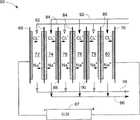
图1示意了本发明的一个实施例超级电容器脱盐装置10。超级电容器脱盐装置10包括一对端电极12、14以及一个位于两端电极12、14之间的双极性电极16。在一个实施例的工作过程中,一个电源(未图示)向两端电极12、14施加相反的电源极性以在两端电极12、14之间产生电场。Fig. 1 schematically shows a supercapacitor desalination device 10 according to an embodiment of the present invention. The supercapacitor desalination device 10 includes a pair of terminal electrodes 12 , 14 and a bipolar electrode 16 located between the two terminal electrodes 12 , 14 . During operation of one embodiment, a power source (not shown) applies opposite power polarities to the two end electrodes 12,14 to generate an electric field between the two end electrodes 12,14.
应当指出的是术语“端电极”是指与电源连接以产生用于水处理电场的电极,但不限于任何特定的结构。术语“双极性电极”是指相反表面在电场作用下均可吸附或者释放离子的电极。双极性电极并不限于一个部件,也可以是由两个单电极以串联方式电性连接组成。It should be noted that the term "terminal electrode" refers to an electrode connected to a power source to generate an electric field for water treatment, but is not limited to any particular structure. The term "bipolar electrode" refers to an electrode whose opposite surfaces can either absorb or release ions under the action of an electric field. The bipolar electrode is not limited to one component, and can also be composed of two single electrodes electrically connected in series.
在图1所示的实施例中,每一端电极12、14都包括一个分别与电源直接连接的集电器20、22以及吸附或者释放离子的多孔层24、26。多孔层24、26可以由多种材料制成,包括但不限于碳、活性炭、石墨、多孔碳颗粒、碳气凝胶或者上述任何两种或者多种材料的混合。在一个实施例中,每一端电极12、14还进一步包括离子交换材料。该离子交换材料可以是阴离子交换材料,也可以是阳离子交换材料。在以下的描述中,离子交换材料也可以是对阴离子交换材料和阳离子交换材料两者的统称。在一个实施例中,离子交换材料允许一种带电离子(阴离子或者阳离子)通过,阻止另一种带电离子(阳离子或者阴离子)通过。In the embodiment shown in FIG. 1 , each terminal electrode 12 , 14 includes a
在一个实施例中,阴离子交换材料允许阴离子通过,阻止阳离子通过。而阳离子交换材料允许阳离子通过,阻止阴离子通过。阴离子包括但不限于氯离子、硫酸盐离子、碳酸盐离子、重碳酸盐离子以及氢氧离子。阳离子包括但不限于钠离子、钙离子、镁离子、钾离子以及质子。在图1所示的实施例中,端电极12、14上的离子交换材料均是允许阴离子通过但阻止阳离子通过的阴离子交换材料28、30。In one embodiment, the anion exchange material allows the passage of anions and blocks the passage of cations. Whereas cation exchange materials allow the passage of cations and block the passage of anions. Anions include, but are not limited to, chloride, sulfate, carbonate, bicarbonate, and hydroxide ions. Cations include, but are not limited to, sodium, calcium, magnesium, potassium, and protons. In the embodiment shown in FIG. 1, the ion exchange materials on the end electrodes 12, 14 are both anion exchange materials 28, 30 that allow the passage of anions but block the passage of cations.
在一个实施例中,双极性电极16包括允许电子通过但阻止离子通过的导电层32、位于导电层32相反表面的一对多孔层34、36以及位于多孔层34、36相反表面上的阳离子交换材料38、40。导电层32具有多种实例,其包括但不限于导电聚合体薄膜、石墨板、金属膜或板以及导电陶瓷膜。可以理解的是,当端电极12、14上的离子交换材料是阳离子交换材料时,图1中的双极性电极16上的阳离子交换材料38、40将替换成阴离子交换材料。In one embodiment, bipolar electrode 16 includes a conductive layer 32 that allows electrons to pass through but blocks ions, a pair of porous layers 34, 36 on opposite surfaces of conductive layer 32, and cations on opposite surfaces of porous layers 34, 36. Exchange material 38, 40. Conductive layer 32 has a variety of examples including, but not limited to, conductive polymer films, graphite plates, metal films or plates, and conductive ceramic films. It will be appreciated that when the ion exchange material on the end electrodes 12, 14 is a cation exchange material, the cation exchange material 38, 40 on the bipolar electrode 16 in FIG. 1 will be replaced by an anion exchange material.
由于端电极12、14、双极性电极16、阳离子交换材料38、40以及阴离子交换材料28、30的容量限制,通过周期性地切换施加的电源极性,使超级电容器脱盐装置交替地在第一阶段和第二阶段下工作。提供电源极性的电源可以自动地进行电极切换,也可以通过设置一个元件,根据预先确定的时间间隔,周期性地切换电源极性。在本实施例中,第一阶段和第二阶段的持续时间相同。持续时间可以根据诸如离子交换材料的容量、端电极和双极性电极的容量、超级电容器脱盐装置的大小、进料流的特性进行调整。Due to capacity limitations of terminal electrodes 12, 14, bipolar electrodes 16, cation exchange materials 38, 40, and anion exchange materials 28, 30, by periodically switching the polarity of the applied power supply, the supercapacitor desalination device is alternately Work on Phase One and Phase Two. The power supply that provides the polarity of the power supply can perform electrode switching automatically, or a component can be set to periodically switch the polarity of the power supply according to a predetermined time interval. In this embodiment, the duration of the first phase and the second phase are the same. The duration can be adjusted based on factors such as the capacity of the ion exchange material, the capacity of the terminal and bipolar electrodes, the size of the supercapacitor desalination unit, and the characteristics of the feed stream.
参阅图1所示,在第一阶段期间,电源的正极与端电极12连接,电源的负极与端电极14连接,这样在超级电容器脱盐装置10内形成一个电场。在第二阶段期间,电源的正极与端电极14连接,电源的负极与端电极12连接,这样在超级电容器脱盐装置10内形成一个与第一阶段期间不同的新电场。Referring to FIG. 1 , during the first stage, the positive pole of the power supply is connected to the terminal electrode 12 , and the negative pole of the power supply is connected to the terminal electrode 14 , so that an electric field is formed in the supercapacitor desalination device 10 . During the second stage, the positive pole of the power supply is connected to the terminal electrode 14 , and the negative pole of the power supply is connected to the terminal electrode 12 , so that a new electric field different from that during the first stage is formed in the supercapacitor desalination device 10 .
在第一阶段期间,第一进料流46流入形成于端电极12和双极性电极16之间的腔室42内。在电场作用下,第一进料流46中的阴离子被吸引着朝向端电极12方向移动。第一进料流46中的阳离子50则被吸引着朝向双极性电极16的一个表面(左表面)移动。During the first stage, a first feed stream 46 flows into the chamber 42 formed between the terminal electrode 12 and the bipolar electrode 16 . Under the action of the electric field, the anions in the first feed stream 46 are attracted to move towards the end electrode 12 . The cations 50 in the first feed stream 46 are then attracted to move towards one surface (the left surface) of the bipolar electrode 16 .
在一个实施例中,阴离子48吸附在阴离子交换材料28以及关联多孔层24上,而阳离子50则吸附在阳离子交换材料38以及关联多孔层34上。由于阳离子50和阴离子48离开第一进料流46,使得第一进料流46变成比先前浓度较低的稀释液47。在第一进料流46的处理过程中,腔室42处于第一阶段起到稀释的作用。而且,在本实施例中,多孔层24、34和离子交换材料28、34的容量均得到有效利用,这种方式扩大了超级电容器脱盐装置10的应用。例如,可以向超级电容器脱盐装置10施加大电流。因此,在一些应用中,超级电容器脱盐装置10可用于处理含高总溶解固体(Total DissolvedSolids,TDS)的水或导电液体。TDS是指溶解的包括矿物质、盐类、金属和阴阳离子的有机、无机物质的总量。In one embodiment, anions 48 are adsorbed on anion exchange material 28 and associated porous layer 24 , while cations 50 are adsorbed on cation exchange material 38 and associated porous layer 34 . As the cations 50 and anions 48 leave the first feed stream 46, the first feed stream 46 becomes a less concentrated diluent 47 than before. During processing of the first feed stream 46, the chamber 42 is in a first stage to act as a dilution. Moreover, in this embodiment, the capacities of the porous layers 24 , 34 and the ion exchange materials 28 , 34 are all effectively utilized, which expands the application of the supercapacitor desalination device 10 . For example, a large current may be applied to the supercapacitor desalination device 10 . Therefore, in some applications, the supercapacitor desalination device 10 can be used to treat water or conductive liquids containing high total dissolved solids (Total Dissolved Solids, TDS). TDS refers to the total amount of dissolved organic and inorganic substances including minerals, salts, metals and anions and cations.
在处理第一进料流46的同时,第二进料流60在位于端电极14和双极性电极16之间的另一腔室44内进行处理。第二进料流60流经腔室44形成浓缩液52。在腔室44内,第二进料流60中的阴离子(未图示)在电场作用下被吸引着朝向双极性电极16的另一表面(右表面)移动。然而,在本实施例中,阳离子交换材料40阻止阴离子进一步移动。代替地,阳离子交换材料40和/或多孔层36内的阳离子进入第二进料流60。另外,由于阴离子交换材料30的阻挡,阳离子62也不能进入端电极14内,这样阳离子62就留在第二进料流60中,导致第二进料流60浓度增加。另一方面,阴离子交换材料30和/或多孔层26中的阴离子64在电场的作用下也进入第二进料流60中。阴离子64和阳离子62进入第二进料流60导致其离子浓度增加,形成浓缩液52,所以说腔室44在第一阶段起浓缩腔室的作用。While the first feed stream 46 is being processed, the second feed stream 60 is being processed in another chamber 44 located between the terminal electrode 14 and the bipolar electrode 16 . The second feed stream 60 flows through the chamber 44 to form the concentrate 52 . Within the chamber 44 , anions (not shown) in the second feed stream 60 are attracted by the electric field to move towards the other surface (right surface) of the bipolar electrode 16 . In this embodiment, however, the cation exchange material 40 prevents further movement of the anions. Instead, cations within cation exchange material 40 and/or porous layer 36 enter second feed stream 60 . In addition, the cations 62 cannot enter the end electrode 14 due to the barrier of the anion exchange material 30, so the cations 62 remain in the second feed stream 60, resulting in an increase in the concentration of the second feed stream 60. On the other hand, anions 64 in the anion exchange material 30 and/or porous layer 26 also enter the second feed stream 60 under the action of the electric field. The entry of anions 64 and cations 62 into second feed stream 60 causes its ion concentration to increase to form concentrate 52, so chamber 44 acts as a concentration chamber in the first stage.
在一个实施例中,阴离子交换材料28、30以及阳离子交换材料38、40设置成与对应的关联多孔层24、34、36、26具有相似的容量。In one embodiment, the anion exchange material 28 , 30 and the cation exchange material 38 , 40 are configured to have a similar capacity as the corresponding associated porous layer 24 , 34 , 36 , 26 .
为了避免混淆,以下将举例说明在前述或者以下描述中提到的“关联电极”、“关联离子交换材料”、“关联多孔层”以及类似术语。参阅图1所示,阴离子交换材料28的关联电极是端电极12,关联多孔层是多孔层24。端电极12的关联离子交换材料是阳离子交换材料28。多孔层34的关联离子交换材料是阳离子交换材料38,阳离子交换材料38的关联多孔层是多孔层34,以此类推。To avoid confusion, "associated electrode", "associated ion exchange material", "associated porous layer" and similar terms mentioned in the preceding or following description will be exemplified below. Referring to FIG. 1 , the associated electrode of the anion exchange material 28 is the terminal electrode 12 , and the associated porous layer is the porous layer 24 . The associated ion exchange material of terminal electrode 12 is cation exchange material 28 . The associated ion exchange material of porous layer 34 is cation exchange material 38, the associated porous layer of cation exchange material 38 is porous layer 34, and so on.
从上述描述中可知,充电模式(稀释过程)和放电模式(浓缩过程)并存于一个单独的超级电容器脱盐装置10内,同时生产稀释液47和浓缩液52。本领域的技术人员可以理解的是超级电容器脱盐装置10第二阶段的工作方式与第一阶段是相反的。在第二阶段期间,腔室42形成浓缩腔室,流过腔室42的进料流变成浓缩液。腔室44形成稀释腔室,流经腔室44的进料流变成稀释液。尽管超级电容器脱盐装置10交替地在第一阶段和第二阶段下工作,但是不管是第一阶段还是第二阶段,均同时存在充电模式和放电模式,因此可以实现连续地生产稀释液和浓缩液。It can be seen from the above description that the charge mode (dilution process) and discharge mode (concentration process) coexist in a single supercapacitor desalination device 10, and dilute liquid 47 and concentrated liquid 52 are produced simultaneously. Those skilled in the art can understand that the working mode of the second stage of the supercapacitor desalination device 10 is opposite to that of the first stage. During the second stage, chamber 42 forms a concentrate chamber, and the feed stream flowing through chamber 42 becomes concentrate. Chamber 44 forms a dilution chamber, and the feed stream flowing through chamber 44 becomes the diluent. Although the supercapacitor desalination device 10 works alternately in the first stage and the second stage, no matter it is the first stage or the second stage, both the charging mode and the discharging mode exist at the same time, so the continuous production of diluent and concentrate can be realized .
另外,在第一阶段吸附到电极上的离子可以在第二阶段的时候释放掉,这样就不需要额外留出时间用于电极再生(恢复电极的吸附能力),从而提高了生产效率。In addition, the ions adsorbed to the electrode in the first stage can be released in the second stage, so that no additional time is required for electrode regeneration (recovering the adsorption capacity of the electrode), thereby improving production efficiency.
在一个实施例中,超级电容器脱盐装置10还包括数个允许离子通过的电绝缘隔网,其分别放置在如图1所示的腔室42、44内。这些隔网用于在电场环境下将电极固定在适当位置上。In one embodiment, the supercapacitor desalination device 10 further includes several electrically insulating partitions that allow ions to pass through, which are respectively placed in the chambers 42 and 44 as shown in FIG. 1 . These spacers are used to hold the electrodes in place in an electric field environment.
在图1所示的第一阶段中,腔室44在放电模式下工作,阳离子62被吸引入第二进料流60内。最初与阳离子62配对的电子穿过导电层32,与阳离子50配对。由于超级电容器脱盐装置10同时存在充电模式和放电模式,这样,不需要额外设置能量回收装置,就实现了实时能量回收。In the first stage shown in FIG. 1 , the chamber 44 is operated in a discharge mode and cations 62 are attracted into the second feed stream 60 . Electrons that initially pair with cation 62 pass through conductive layer 32 to pair with cation 50 . Since the supercapacitor desalination device 10 has a charging mode and a discharging mode at the same time, real-time energy recovery is realized without an additional energy recovery device.
需要指出的是,在前述和以下的各种实施例中,离子交换材料例如28、30、38、40具有多种存在形式,可以层状结构、薄膜,也可以是颗粒状结构。在一个实施例中,离子交换材料呈层状,具有涂敷在关联电极的表面上的至少一层涂层。在另一实施例中,离子交换材料呈颗粒状,其中至少部分颗粒分布在关联电极的内部。这些颗粒也可以采用包埋、混合、植入技术或者各种沉积技术设置于关联电极的表面上。在其他的另一实施例中,离子交换材料部分埋入关联电极例如12、14、16内,其他部分则以薄膜的形式存在于电极12、14、16表面上。It should be pointed out that in the foregoing and following various embodiments, the ion exchange materials such as 28, 30, 38, 40 exist in various forms, such as layered structure, thin film, or granular structure. In one embodiment, the ion exchange material is in the form of a layer with at least one coating applied to the surface of the associated electrode. In another embodiment, the ion exchange material is in the form of particles, wherein at least some of the particles are distributed inside the associated electrode. These particles can also be provided on the surface of the associated electrode using embedding, mixing, implantation techniques or various deposition techniques. In yet another embodiment, the ion exchange material is partly embedded in the associated electrode, such as 12, 14, 16, and the other part is present in the form of a thin film on the surface of the electrode 12, 14, 16.
在一个实施例中,超级电容器脱盐装置10用于处理一种溶液,其设有百万分之(parts per million,ppm)800的氯化钠(NaCl)。在本实施例中,该溶液分为两股,分别是图1所示的第一进料流46和第二进料流60。第一进料流46和第二进料流60分别引入腔室42、44中。腔室42、44在图1所示的第一阶段中分别形成稀释腔室和浓缩腔室。该溶液的流量是780毫升每分钟。在处理过程中,超级电容器脱盐装置10施加上相反的电源极性,且周期性地在第一阶段施加8分钟的负1.25安培(A)的恒定电流,在第二阶段施加8分钟的正1.25A的恒定电流。其中分配30秒的时间用于在第一阶段和第二阶段之间切换。本实施例将电流作为基准参数来控制超级电容器脱盐装置10工作在稳定电场下。而电压是根据上述的恒定电流检测获得的。图2示意了超级电容器脱盐装置10在0~6500秒期间的充电曲线,其中该超级电容器脱盐装置10在这段时间内经历了7次第一阶段和6次第二阶段。In one embodiment, the supercapacitor desalination device 10 is used to process a solution having 800 parts per million (ppm) of sodium chloride (NaCl). In this example, the solution is divided into two streams, the first feed stream 46 and the second feed stream 60 shown in FIG. 1 . The first feed stream 46 and the second feed stream 60 are introduced into chambers 42, 44, respectively. The chambers 42, 44 form the diluting and concentrating chambers, respectively, in the first stage shown in Fig. 1 . The flow rate of the solution was 780 ml per minute. During the process, the supercapacitor desalination device 10 is applied with the opposite power polarity, and periodically applies a constant current of negative 1.25 amperes (A) for 8 minutes in the first phase and a positive 1.25 ampere (A) for 8 minutes in the second phase. A constant current. 30 seconds are allotted for switching between phase one and phase two. In this embodiment, the current is used as a reference parameter to control the supercapacitor desalination device 10 to work in a stable electric field. And the voltage is obtained according to the above-mentioned constant current detection. Fig. 2 schematically shows the charging curve of the supercapacitor desalination device 10 during 0-6500 seconds, wherein the supercapacitor desalination device 10 has experienced 7 times of the first stage and 6 times of the second stage during this period.
在本实施例中,采用一个测量装置对腔室输出溶液中钠离子和氯离子的浓度进行测量。该测量装置采用电导率来表示溶液浓度。本领域的技术人员可以理解的是,含有800ppm氯化钠的溶液的电导率约为1.6每厘米毫西门子(mS/cm)。该测量装置输出的测量结果显示在第一阶段腔室42和44内溶液的电导率分别约为1.5mS/cm和1.7mS/cm,在第二阶段则分别约为1.7mS/cm和1.5mS/cm。图3示意了腔室42流出溶液的部分测量结果,其显示了腔室42交替地工作在充电模式和放电模式下。因此,可知超级电容器脱盐装置10在整个处理过程中,可以连续地生产稀释液和浓缩液。In this embodiment, a measuring device is used to measure the concentrations of sodium ions and chloride ions in the chamber output solution. This measuring device uses conductivity as an indication of solution concentration. Those skilled in the art will understand that the conductivity of a solution containing 800 ppm sodium chloride is about 1.6 millisiemens per centimeter (mS/cm). The measurement results output by the measuring device show that the conductivity of the solution in the first stage chambers 42 and 44 is about 1.5 mS/cm and 1.7 mS/cm, respectively, and in the second stage is about 1.7 mS/cm and 1.5 mS respectively. /cm. FIG. 3 schematically shows partial measurements of the solution flowing out of the chamber 42, which shows that the chamber 42 operates alternately in a charge mode and a discharge mode. Therefore, it can be seen that the supercapacitor desalination device 10 can continuously produce diluent and concentrate during the whole process.
容易理解的是,在端电极12、14之间可以设置多于一个双极性电极16,这样可以形成多个腔室以同时处理多股进料流,从而提高产能。在一个实施例中,这些双极性电极分为两组,其中第一组中所有的双极性电极的相反表面上均设有阳离子交换材料,第二组中所有的双极性电极的相反表面上均设有阴离子交换材料。It will be readily understood that more than one bipolar electrode 16 can be positioned between the terminal electrodes 12, 14, so that multiple chambers can be formed to process multiple feed streams simultaneously, thereby increasing throughput. In one embodiment, the bipolar electrodes are divided into two groups, wherein all bipolar electrodes in the first group are provided with cation exchange material on opposite surfaces and all bipolar electrodes in the second group are provided on opposite surfaces. Anion exchange materials are provided on the surface.
图4示意了本发明的另一实施例具有数个双极性电极的超级电容器脱盐系统66。超级电容器脱盐系统66包括超级电容器脱盐装置(未标示)以及向超级电容器脱盐装置施加相反电极极性的电源67。该超级电容器脱盐装置包括一对端电极68、70、5个双极性电极以及位于端电极68、70和5个双极性电极之间的6个腔室72、74、76、78、79、80。Figure 4 illustrates another embodiment of the present invention with a
在图4所示的实施例中,5个双极性电极双极性电极包括3个第一双极性电极82、84、86以及2个第二双极性电极88、90,两种双极性电极交替地放置在端电极68、70之间。每一第一双极性电极82、84、86的相反表面上设有阳离子交换材料(未标示),每一第二双极性电极80、90的相反表面上设有阴离子交换材料(未标示)。In the embodiment shown in FIG. 4, the 5 bipolar electrodes bipolar electrodes include 3 first
所述端电极68、70可以设置成上述任一实施例中的结构。在一个实施例中,两端电极68、70的一个表面上设有离子交换材料。需要指出的是双极性电极的数量影响端电极68、70上离子交换材料类型的选择。例如,如果第一和第二双极性电极的数目相同,那么一个端电极上是阴离子交换材料,另一个端电极上是阳离子交换材料。反之,两端电极68、70上的离子交换材料要么都是阴离子交换材料,要么都是阳离子交换材料。The
在图4所示的实施例中,两端电极68、70在一侧表面上均有阴离子交换材料。第一双极性电极82、84、86的相反表面上均设有阳离子交换材料,第二双极性电极80、90的相反表面上均设有阴离子交换材料。当如图4所示的向端电极68、70施加相反电源极性时,腔室72、76、79形成稀释腔室,而腔室74、78、80形成浓缩腔室。换句话说,流经腔室72、76、79的进料流变成稀释液,流经腔室74、78、80的进料流变成浓缩液。In the embodiment shown in FIG. 4, both
为了描述方便,以下将待稀释的水或者溶液定义为稀释进料流,待浓缩的水或溶液定义为浓缩进料流。参阅图4所示,从一个储液池出来的三股稀释进料流92分别引入腔室72、76、79进行处理,三股浓缩进料流94分别引入腔室74、78、80进行处理。在处理过程中,流经腔室72、76、79的稀释进料流92中的离子例如氯离子和钠离子在电场的作用下,吸附到关联离子交换材料和/或关联电极(端电极或者双极性电极)上。然后,三股稀释液流96流出腔室72、76、79。在腔室74、78、80中,离子交换材料和/或电极上的离子例如氯离子和钠离子在电场的作用下,脱离离子交换材料和/或电极进入浓缩进料流94内,形成浓缩液流98。For the convenience of description, the water or solution to be diluted is defined as the diluted feed stream, and the water or solution to be concentrated is defined as the concentrated feed stream. Referring to Fig. 4, three
该超级电容器脱盐装置与图1所示的超级电容器脱盐装置10具有类似结构。由于电极容量的限制,也需要周期性地切换电源67的电源极性,以使该超级电容器脱盐装置交替地在第一阶段和第二阶段工作。图4示意了在第一阶段工作的超级电容器脱盐系统66。图5示意了在第二阶段工作的超级电容器脱盐系统66。在一个实施例的工作过程中,随着第一阶段和第二阶段切换,需要切换稀释和浓缩进料流92、94的引入位置。因此在第二阶段期间,稀释液流96从腔室74、78、80流出,浓缩液流98则从腔室72、76、79流出。这样,使用超级电容器脱盐系统66可以连续地生产稀释液和浓缩液。The supercapacitor desalination device has a similar structure to the supercapacitor desalination device 10 shown in FIG. 1 . Due to the limitation of electrode capacity, it is also necessary to periodically switch the power supply polarity of the
需要指出的是超级电容器脱盐系统66中的电极,包括端电极和双极性电极可以设置成上述任何一种实施例中的结构。氯离子和钠离子仅仅是出现在图4和图5中的实施例,包括其他类型离子的进料流也可以使用该超级电容器脱盐系统66进行处理。It should be pointed out that the electrodes in the
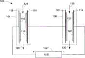
图6示意本发明其他的另一实施例超级电容器脱盐系统100。该超级电容器脱盐系统100包括电源102以及两个超级电容器脱盐堆体104、106。该电源102可以提供预定电压或者电流,以使超级电容器脱盐堆体104、106在电场下工作。容易理解的是,根据产能的要求,该超级电容器脱盐系统100还可以设置多于两个超级电容器脱盐堆体。在图6所示的实施例中,每一超级电容器脱盐堆体104、106包括两个单电极108、110、112、114,每一单电极108、110、112、114在一个表面上设有离子交换材料116、118、120、122。离子交换材料是阴离子交换材料或者是阳离子交换材料。单电极108、110、112、114中具有相同离子交换材料的电性连接在一起,剩下两个单电极分别与电源的正极和负极连接。Fig. 6 schematically shows another
在本实施例中,单电极108、114在一侧表面上设有阴离子交换材料116、122,单电极110、112在其一侧表面上设有阳离子交换材料118、120。而且,单电极110、112以串联方式电性连接在一起,而单电极108、114起端电极的作用,分别与电源102的正极和负极连接。In this embodiment, the
在图6所示实施例的工作过程中,超级电容器脱盐堆体104处于充电模式下,超级电容器脱盐堆体106处于放电模式下。当进料流124、126分别流经超级电容器脱盐堆体104、106时,进料流124中阴离子和阳离子(未图示)在电场作用下吸附到阴离子交换材料116、阳离子交换材料118和/或单电极108、110上(充电过程),这样流出超级电容器脱盐堆体104是稀释液128。在超级电容器脱盐堆体106中,阳离子交换材料120、阴离子交换材料122和/或单电极112、114中的阴离子和阳离子在电场作用下,释放入进料流126中,形成浓缩液130。During the working process of the embodiment shown in FIG. 6 , the
当阴离子交换材料116、阳离子交换材料118和/或单电极108、110的容量饱和或者接近饱和的情况下,切换电源极性以使超级电容器脱盐系统100在与前一电场相反的新电场作用下工作。这时,根据电源极性的切换来切换进料流124、126的引入位置。这样,稀释液128从超级电容器脱盐堆体106输出,浓缩液130则从超级电容器脱盐堆体104输出。When the capacity of the
在超级电容器脱盐系统100中,放电模式和充电模式并存在整个处理过程中,因此,只要根据电源极性的切换频率来切换输入的进料流,就可以连续的产生稀释液128和浓缩液130。In the
参阅图6所示,如上面所述,一个超级电容器脱盐系统中100同时并存放电模式和充电模式。在超级电容器脱盐堆体106放电模式期间,单电极112中的离子脱离单电极进入进料流126中,而先前与这些离子配对的电子通过导线或者其他电性元件转移到超级电容器脱盐堆体104的单电极110和/或阳离子交换材料118上。这样,超级电容器脱盐系统100在同一个系统内进行能量回收,减低了综合能耗。Referring to FIG. 6 , as mentioned above, a
在一个实施例中,为了满足实际应用,超级电容器脱盐系统100包括多于两个连接在一起的超级电容器脱盐堆体。每一超级电容器脱盐堆体具有与超级电容器脱盐堆体104或者超级电容器脱盐堆体106类似的结构。在本实施例中,相邻单电极对例如110、112通过导线或者其他导电元件以串联方式电性连接在一起。In one embodiment, in order to meet practical applications, the
在一个实施例中,每一超级电容器脱盐堆体还包括至少一个位于单电极108、110、112、114之间的双极性电极,这样在一个超级电容器脱盐堆体内形成数个腔室。在另一实施例中,每一双极性电极在相反表面上设有离子交换材料。在其他的另一实施例中,每一超级电容器脱盐堆体设有多于一个腔室,且可以设置成上述超级电容器脱盐装置任一实施例的结构,例如图1中的超级电容器脱盐装置10以及图4中的超级电容器脱盐系统66。In one embodiment, each supercapacitor desalination stack further includes at least one bipolar electrode located between the
在一些应用中,至少一个超级电容器脱盐堆体还包括至少一个双极性电极,且该至少一个双极性电极的一个表面上设有阳离子交换材料,另一表面上设有阴离子交换材料。这样,在工作过程中,该至少一个超级电容器脱盐堆体内的所有腔室将均处于放电模式下或者均处于充电模式下。In some applications, the at least one supercapacitor desalination stack further includes at least one bipolar electrode, and the at least one bipolar electrode is provided with a cation exchange material on one surface and an anion exchange material on the other surface. In this way, during the working process, all the chambers in the at least one supercapacitor desalination stack will be in the discharge mode or in the charge mode.
虽然结合特定的实施例对本发明进行了说明,但本领域的技术人员可以对本发明作出许多修改和变型。因此,要认识到,权利要求书意图覆盖在本发明真正构思范围内的所有这些修改和变型。Although the invention has been described in conjunction with specific embodiments thereof, many modifications and variations of the invention will occur to those skilled in the art. It is, therefore, to be realized that the appended claims are intended to cover all such modifications and variations as are within the true spirit of the invention.
Claims (13)
Priority Applications (2)
| Application Number | Priority Date | Filing Date | Title |
|---|---|---|---|
| CN 201010252556CN102372345B (en) | 2010-08-10 | 2010-08-10 | Super capacitor desalination apparatus and desalination method |
| US13/033,625US8882981B2 (en) | 2010-08-10 | 2011-02-24 | Super-capacitor desalination devices and methods |
Applications Claiming Priority (1)
| Application Number | Priority Date | Filing Date | Title |
|---|---|---|---|
| CN 201010252556CN102372345B (en) | 2010-08-10 | 2010-08-10 | Super capacitor desalination apparatus and desalination method |
Publications (2)
| Publication Number | Publication Date |
|---|---|
| CN102372345A CN102372345A (en) | 2012-03-14 |
| CN102372345Btrue CN102372345B (en) | 2013-07-31 |
Family
ID=45564015
Family Applications (1)
| Application Number | Title | Priority Date | Filing Date |
|---|---|---|---|
| CN 201010252556ActiveCN102372345B (en) | 2010-08-10 | 2010-08-10 | Super capacitor desalination apparatus and desalination method |
Country Status (2)
| Country | Link |
|---|---|
| US (1) | US8882981B2 (en) |
| CN (1) | CN102372345B (en) |
Families Citing this family (12)
| Publication number | Priority date | Publication date | Assignee | Title |
|---|---|---|---|---|
| CN103058425B (en)* | 2011-10-21 | 2015-07-29 | 通用电气公司 | desalination system and method |
| WO2015060655A1 (en)* | 2013-10-23 | 2015-04-30 | 주식회사 아모그린텍 | Composite electrode for desalination comprising ion-exchange membrane, manufacturing method thereof, and desalination apparatus using same |
| KR101655363B1 (en) | 2013-11-21 | 2016-09-07 | 주식회사 아모그린텍 | Deionization Equipment |
| NL2012138C2 (en)* | 2014-01-24 | 2015-07-29 | Voltea Bv | Apparatus for removal of ions from water and method of producing the same. |
| CN106898803A (en)* | 2015-12-18 | 2017-06-27 | 王冰 | A kind of multiple-effect photosynthesis microorganism fuel cell and implementation method |
| US9751779B1 (en)* | 2016-10-17 | 2017-09-05 | Sultan Qaboos University | Three-electrode structure for capacitive deionization desalination |
| AT519418A1 (en)* | 2016-12-05 | 2018-06-15 | Pro Aqua Diamantelektroden Produktion Gmbh & Co Kg | Method and device for producing at least one liquid reaction product |
| CN109081404A (en)* | 2017-06-13 | 2018-12-25 | 郭洪飞 | A kind of electrode structure of capacitor deionizing instrument |
| CN109052587A (en)* | 2017-06-13 | 2018-12-21 | 郭洪飞 | A kind of open capacitive deionization desalter |
| CN109879492A (en)* | 2019-03-13 | 2019-06-14 | 佛山市云米电器科技有限公司 | A pure water machine membrane filtration system with desalination device |
| US20210163319A1 (en)* | 2019-12-03 | 2021-06-03 | Iucf-Hyu (Industry-University Cooperation Foundation Hanyang University) | Water treatment apparatus and water treatment method using same |
| KR102593588B1 (en)* | 2019-12-03 | 2023-10-24 | 한양대학교 산학협력단 | Water treatment apparatus and water treatment method using same |
Citations (5)
| Publication number | Priority date | Publication date | Assignee | Title |
|---|---|---|---|---|
| CN1678533A (en)* | 2002-07-01 | 2005-10-05 | 栗田工业株式会社 | Electrodeionization device |
| EP0760805B1 (en)* | 1994-05-20 | 2008-01-02 | The Regents Of The University Of California | Method and apparatus for capacitive deionization and electrochemical purification and regeneration of electrodes |
| CN101331088A (en)* | 2005-12-14 | 2008-12-24 | 通用电气公司 | Supercapacitor desalination devices |
| CN101563296A (en)* | 2006-12-19 | 2009-10-21 | 通用电气公司 | Super-capacitor type desalination device and manufacturing method thereof |
| CN101595064A (en)* | 2007-02-01 | 2009-12-02 | 通用电气公司 | The desalting method and the device that comprise electrode of super capacitor |
Family Cites Families (8)
| Publication number | Priority date | Publication date | Assignee | Title |
|---|---|---|---|---|
| US5074988A (en)* | 1986-02-20 | 1991-12-24 | Raychem Corporation | Apparatus for monitoring an electrolyte |
| US5017274A (en)* | 1987-02-25 | 1991-05-21 | Aquanautics Corporation | Method and systems for extracting oxygen employing electrocatalysts |
| JPH0342167A (en)* | 1989-07-07 | 1991-02-22 | Kawasaki Steel Corp | Manufacture of high melting point metal-made laminated pipe |
| US6709560B2 (en)* | 2001-04-18 | 2004-03-23 | Biosource, Inc. | Charge barrier flow-through capacitor |
| JP4454502B2 (en) | 2002-12-27 | 2010-04-21 | 荏原エンジニアリングサービス株式会社 | Electric desalination equipment |
| DE102006016688B3 (en)* | 2006-04-08 | 2007-09-20 | Esa Patentverwertungsagentur Sachsen-Anhalt Gmbh | Electrodeionization process for the treatment of rinsing waters resulting from the chemical and / or electrochemical surface treatment of metals |
| BRPI0720810A2 (en) | 2007-02-01 | 2014-03-04 | Gen Electric | SYSTEM AND METHOD FOR LIQUID TREATMENT |
| EP2212254B1 (en) | 2007-11-13 | 2017-01-11 | Voltea Limited | Water purification device |
- 2010
- 2010-08-10CNCN 201010252556patent/CN102372345B/enactiveActive
- 2011
- 2011-02-24USUS13/033,625patent/US8882981B2/enactiveActive
Patent Citations (5)
| Publication number | Priority date | Publication date | Assignee | Title |
|---|---|---|---|---|
| EP0760805B1 (en)* | 1994-05-20 | 2008-01-02 | The Regents Of The University Of California | Method and apparatus for capacitive deionization and electrochemical purification and regeneration of electrodes |
| CN1678533A (en)* | 2002-07-01 | 2005-10-05 | 栗田工业株式会社 | Electrodeionization device |
| CN101331088A (en)* | 2005-12-14 | 2008-12-24 | 通用电气公司 | Supercapacitor desalination devices |
| CN101563296A (en)* | 2006-12-19 | 2009-10-21 | 通用电气公司 | Super-capacitor type desalination device and manufacturing method thereof |
| CN101595064A (en)* | 2007-02-01 | 2009-12-02 | 通用电气公司 | The desalting method and the device that comprise electrode of super capacitor |
Also Published As
| Publication number | Publication date |
|---|---|
| US20120037511A1 (en) | 2012-02-16 |
| CN102372345A (en) | 2012-03-14 |
| US8882981B2 (en) | 2014-11-11 |
Similar Documents
| Publication | Publication Date | Title |
|---|---|---|
| CN102372345B (en) | Super capacitor desalination apparatus and desalination method | |
| Jeon et al. | Ion storage and energy recovery of a flow-electrode capacitive deionization process | |
| CN103058425B (en) | desalination system and method | |
| US10259728B2 (en) | Apparatus and process for separation and selective recomposition of ions | |
| KR102093443B1 (en) | Capacitive deionization apparatus and methods of treating fluid using the same | |
| CN107624106A (en) | Method for continuous water desalination and ion separation by capacitive deionization and its single-module flow electrode device | |
| JP3893740B2 (en) | Electrolytic capacitor type desalting apparatus and desalting method | |
| KR102268476B1 (en) | Multi-channel membrane capacitive deionization with enhanced deionization performance | |
| AU2019237168B2 (en) | Deionization device and method for at least partially deionizing a feed liquid in which an electrolyte is dissolved, and apparatuses using such devices | |
| JP5868421B2 (en) | Electrodeionization equipment | |
| KR101732188B1 (en) | Apparatus for treating water using capacitive deionization and carbon electrode | |
| CN102992522A (en) | Desalination system and method | |
| KR101394112B1 (en) | Water treatment cell by electrosorption, Electrosorptive water treatment apparatus and method using the same | |
| Wang et al. | Removal of Sr2+ ions from simulated wastewater by electrodeionization | |
| CN102745783A (en) | Water-based solution ion separation device and method | |
| TWI498287B (en) | Super-capacitor desalination devices and methods | |
| CN111137956A (en) | A fixed bed electrode electrochemical desalination device and method | |
| Volfkovich | Capacitive deionization of water | |
| KR101850787B1 (en) | Capacitive deionization apparatus and method for adsorbing ions in feed solution using the same | |
| KR20160035896A (en) | Capacitive deionization type water treatment cell and water treatment apparatus having the same | |
| CN118751066A (en) | An electrodialysis device for enriching low-concentration weak acid-base solution and an enrichment method thereof | |
| KR20220065181A (en) | Deionization device | |
| Tate | Electrodeionization basics |
Legal Events
| Date | Code | Title | Description |
|---|---|---|---|
| C06 | Publication | ||
| PB01 | Publication | ||
| C10 | Entry into substantive examination | ||
| SE01 | Entry into force of request for substantive examination | ||
| C14 | Grant of patent or utility model | ||
| GR01 | Patent grant | ||
| TR01 | Transfer of patent right | Effective date of registration:20190103 Address after:American Minnesota Patentee after:BL Technology Co., Ltd. Address before:American New York Patentee before:General Electric Company | |
| TR01 | Transfer of patent right |