CN102367813A - Nozzle of bladeless fan - Google Patents
Nozzle of bladeless fanDownload PDFInfo
- Publication number
- CN102367813A CN102367813ACN2011103160244ACN201110316024ACN102367813ACN 102367813 ACN102367813 ACN 102367813ACN 2011103160244 ACN2011103160244 ACN 2011103160244ACN 201110316024 ACN201110316024 ACN 201110316024ACN 102367813 ACN102367813 ACN 102367813A
- Authority
- CN
- China
- Prior art keywords
- housing
- guide plate
- air
- nozzle
- opening
- Prior art date
- Legal status (The legal status is an assumption and is not a legal conclusion. Google has not performed a legal analysis and makes no representation as to the accuracy of the status listed.)
- Pending
Links
- 230000007704transitionEffects0.000claimsdescription6
- 238000000034methodMethods0.000description4
- 230000009286beneficial effectEffects0.000description1
- 238000004891communicationMethods0.000description1
- 230000007812deficiencyEffects0.000description1
- 238000005516engineering processMethods0.000description1
- 238000004804windingMethods0.000description1
Images


Classifications
- F—MECHANICAL ENGINEERING; LIGHTING; HEATING; WEAPONS; BLASTING
- F04—POSITIVE - DISPLACEMENT MACHINES FOR LIQUIDS; PUMPS FOR LIQUIDS OR ELASTIC FLUIDS
- F04D—NON-POSITIVE-DISPLACEMENT PUMPS
- F04D25/00—Pumping installations or systems
- F04D25/02—Units comprising pumps and their driving means
- F04D25/08—Units comprising pumps and their driving means the working fluid being air, e.g. for ventilation
- F—MECHANICAL ENGINEERING; LIGHTING; HEATING; WEAPONS; BLASTING
- F04—POSITIVE - DISPLACEMENT MACHINES FOR LIQUIDS; PUMPS FOR LIQUIDS OR ELASTIC FLUIDS
- F04F—PUMPING OF FLUID BY DIRECT CONTACT OF ANOTHER FLUID OR BY USING INERTIA OF FLUID TO BE PUMPED; SIPHONS
- F04F5/00—Jet pumps, i.e. devices in which flow is induced by pressure drop caused by velocity of another fluid flow
- F04F5/14—Jet pumps, i.e. devices in which flow is induced by pressure drop caused by velocity of another fluid flow the inducing fluid being elastic fluid
- F04F5/16—Jet pumps, i.e. devices in which flow is induced by pressure drop caused by velocity of another fluid flow the inducing fluid being elastic fluid displacing elastic fluids
- F—MECHANICAL ENGINEERING; LIGHTING; HEATING; WEAPONS; BLASTING
- F04—POSITIVE - DISPLACEMENT MACHINES FOR LIQUIDS; PUMPS FOR LIQUIDS OR ELASTIC FLUIDS
- F04F—PUMPING OF FLUID BY DIRECT CONTACT OF ANOTHER FLUID OR BY USING INERTIA OF FLUID TO BE PUMPED; SIPHONS
- F04F5/00—Jet pumps, i.e. devices in which flow is induced by pressure drop caused by velocity of another fluid flow
- F04F5/44—Component parts, details, or accessories not provided for in, or of interest apart from, groups F04F5/02 - F04F5/42
- F04F5/46—Arrangements of nozzles
Landscapes
- Engineering & Computer Science (AREA)
- Mechanical Engineering (AREA)
- General Engineering & Computer Science (AREA)
- Physics & Mathematics (AREA)
- Fluid Mechanics (AREA)
- Structures Of Non-Positive Displacement Pumps (AREA)
Abstract
Description
Technical field
The invention belongs to the fan technical field, the concrete nozzle that relates to a kind of on-bladed fan.
Background technique
The on-bladed fan is generally all to a side air-out, and like number of patent application: 200810177844.8 disclose a kind of on-bladed fan, and the nozzle of this on-bladed fan is the housing of a circle annular; Enclosure interior is provided with air intake passage; Also be provided with the opening that a circle communicates with passage on the housing, during use, air-flow feeds in the housing; In the entering air intake passage, blow out via opening again.The opening of this nozzle generally can only be towards a side.What wind-force can influence is limited in scope, at some many and also disperse in, all have man-hour just can not satisfy the demands at the tow sides of fan.
Summary of the invention
The present invention is directed to deficiency of the prior art, a kind of nozzle of on-bladed fan is provided, can dry simultaneously, satisfy the demand that man-hour is all arranged at the tow sides of fan to both sides.
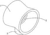
In order to solve the problems of the technologies described above; The present invention is able to solve through following technical proposals: a kind of nozzle of on-bladed fan, comprise the annular housing of a circle, and said enclosure interior is provided with air intake passage; Said housing is provided with the opening that communicates with said air intake passage; Also comprise the guide plate of a circle annular, said guide plate is positioned at the inner ring of said housing, and said guide plate is fixed on the said housing; Form the air-out passage with two exhaust outlets that are oppositely arranged, said air-out passage of said open communication and said air intake passage between the outer ring of said guide plate and the inner ring of said housing.After air-flow blows out opening from air intake passage, get into the air-out passage, from two exhaust outlets that are oppositely arranged, blow out then, air-flow can be simultaneously blows out from the tow sides of nozzle like this, the occasion when being particluarly suitable for some fan tow sides and all the people being arranged.
In the technique scheme, the concrete a kind of guide plate and the means of fixation of housing do, also comprises link, and said link one end is fixed on the said housing, and the other end of said link is fixed on the said guide plate.The link here can be plate or bar.
In the technique scheme, the means of fixation of another kind of guide plate and housing does, also comprises screw bolt and nut, and said bolt passes after said housing and the said guide plate and said nut bolt.This mode guide plate can be dismantled.
In the technique scheme, the inner ring of preferred said housing is positioned at the diameter minimum at said opening two ends, becomes big gradually to the housing two ends.Help like this spreading from the air-flow that exhaust outlet blows out.
The invention has the beneficial effects as follows: after air-flow blows out opening from air intake passage; Get into the air-out passage; From two exhaust outlets that are oppositely arranged, blow out then, air-flow can be simultaneously blows out from the tow sides of nozzle like this, the occasion when being particluarly suitable for some fan tow sides and all the people being arranged.
Description of drawings
Fig. 1 is the schematic perspective view of first embodiment of the invention.
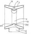
Fig. 2 is the floor map of first embodiment of the invention.
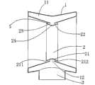
Fig. 3 is the partial enlarged drawing of Fig. 2.
Fig. 4 is the schematic representation of second embodiment of the invention.
Fig. 5 is the schematic representation of third embodiment of the invention.
Embodiment
Below in conjunction with accompanying drawing and embodiment the present invention is described in further detail:
Present embodiment adopts rod member aslink 4, realizes being connected betweenguide plate 2 and the housing 1.Rod member one end is fixed onair intake passage 11 inwalls, and the other end of rod member is fixed on thearc transition face 24 ofguide plate 2 after passing opening 12.
Claims (5)
1. the nozzle of an on-bladed fan; The housing (1) that comprises a circle annular; Said housing (1) set inside has air intake passage (11), and said housing (1) is provided with the opening (12) that communicates with said air intake passage (11), it is characterized in that: the guide plate (2) that also comprises a circle annular; Said guide plate (2) is positioned at the inner ring of said housing (1); Said guide plate (2) is fixed on the said housing (1), forms the air-out passage (21) with two exhaust outlets that are oppositely arranged (211,212) between the inner ring of the outer ring of said guide plate (2) and said housing (1), and said opening (12) is communicated with said air-out passage (21) and said air intake passage (11).
2. the nozzle of on-bladed fan according to claim 1 is characterized in that: also comprise link (4), said link (4) one ends are fixed on the said housing (1), and the other end of said link (4) is fixed on the said guide plate (2).
3. the nozzle of on-bladed fan according to claim 1 is characterized in that: also comprise bolt (51) and nut (52), said bolt (51) passes after said housing (1) and the said guide plate (2) and said nut (52) bolt.
4. according to the nozzle of each described on-bladed fan in the claim 1 to 3, it is characterized in that: the inner ring of said housing (1) is positioned at the diameter minimum that said opening (12) is located two ends, becomes big gradually to housing (1) two ends.
5. the nozzle of on-bladed fan according to claim 4; It is characterized in that: the outer ring of said guide plate (2) is made up of with the arc transition face (24) that is connected two said round table surface (22,23) two round table surface (22,23); Said arc transition face (24) is positioned at said opening (12) over against locating, and said round table surface (22,23) is parallel respectively with said housing (1) inner ring that is positioned at said opening (12) both sides.
Priority Applications (1)
| Application Number | Priority Date | Filing Date | Title |
|---|---|---|---|
| CN2011103160244ACN102367813A (en) | 2011-09-30 | 2011-09-30 | Nozzle of bladeless fan |
Applications Claiming Priority (1)
| Application Number | Priority Date | Filing Date | Title |
|---|---|---|---|
| CN2011103160244ACN102367813A (en) | 2011-09-30 | 2011-09-30 | Nozzle of bladeless fan |
Publications (1)
| Publication Number | Publication Date |
|---|---|
| CN102367813Atrue CN102367813A (en) | 2012-03-07 |
Family
ID=45760400
Family Applications (1)
| Application Number | Title | Priority Date | Filing Date |
|---|---|---|---|
| CN2011103160244APendingCN102367813A (en) | 2011-09-30 | 2011-09-30 | Nozzle of bladeless fan |
Country Status (1)
| Country | Link |
|---|---|
| CN (1) | CN102367813A (en) |
Cited By (74)
| Publication number | Priority date | Publication date | Assignee | Title |
|---|---|---|---|---|
| US8348596B2 (en) | 2009-03-04 | 2013-01-08 | Dyson Technology Limited | Fan assembly |
| US8348629B2 (en) | 2008-09-23 | 2013-01-08 | Dyston Technology Limited | Fan |
| US8366403B2 (en) | 2010-08-06 | 2013-02-05 | Dyson Technology Limited | Fan assembly |
| US8403650B2 (en) | 2007-09-04 | 2013-03-26 | Dyson Technology Limited | Fan |
| US8403640B2 (en) | 2009-03-04 | 2013-03-26 | Dyson Technology Limited | Fan assembly |
| US8408869B2 (en) | 2009-03-04 | 2013-04-02 | Dyson Technology Limited | Fan assembly |
| US8430624B2 (en) | 2009-03-04 | 2013-04-30 | Dyson Technology Limited | Fan assembly |
| US8454322B2 (en) | 2009-11-06 | 2013-06-04 | Dyson Technology Limited | Fan having a magnetically attached remote control |
| US8469660B2 (en) | 2009-03-04 | 2013-06-25 | Dyson Technology Limited | Fan assembly |
| US8469658B2 (en) | 2009-03-04 | 2013-06-25 | Dyson Technology Limited | Fan |
| GB2499042A (en)* | 2012-02-06 | 2013-08-07 | Dyson Technology Ltd | A nozzle for a fan assembly |
| US8529203B2 (en) | 2009-03-04 | 2013-09-10 | Dyson Technology Limited | Fan assembly |
| CN103410710A (en)* | 2013-08-28 | 2013-11-27 | 苏州萤火虫贸易有限公司 | Double-end air outlet face cover |
| CN103410754A (en)* | 2013-08-28 | 2013-11-27 | 苏州萤火虫贸易有限公司 | Bladeless double head fan |
| CN103410769A (en)* | 2013-08-28 | 2013-11-27 | 苏州萤火虫贸易有限公司 | Double-end air suction assembly |
| US8613601B2 (en) | 2009-03-04 | 2013-12-24 | Dyson Technology Limited | Fan assembly |
| US20140077398A1 (en)* | 2012-03-06 | 2014-03-20 | Dyson Technology Limited | Humidifying apparatus |
| US8714937B2 (en) | 2009-03-04 | 2014-05-06 | Dyson Technology Limited | Fan assembly |
| US8721286B2 (en) | 2009-03-04 | 2014-05-13 | Dyson Technology Limited | Fan assembly |
| US8734094B2 (en) | 2010-08-06 | 2014-05-27 | Dyson Technology Limited | Fan assembly |
| US8770946B2 (en) | 2010-03-23 | 2014-07-08 | Dyson Technology Limited | Accessory for a fan |
| US8783663B2 (en) | 2009-03-04 | 2014-07-22 | Dyson Technology Limited | Humidifying apparatus |
| US8784071B2 (en) | 2009-03-04 | 2014-07-22 | Dyson Technology Limited | Fan assembly |
| US8873940B2 (en) | 2010-08-06 | 2014-10-28 | Dyson Technology Limited | Fan assembly |
| US8882451B2 (en) | 2010-03-23 | 2014-11-11 | Dyson Technology Limited | Fan |
| US8894354B2 (en) | 2010-09-07 | 2014-11-25 | Dyson Technology Limited | Fan |
| US8967979B2 (en) | 2010-10-18 | 2015-03-03 | Dyson Technology Limited | Fan assembly |
| US8967980B2 (en) | 2010-10-18 | 2015-03-03 | Dyson Technology Limited | Fan assembly |
| US9011116B2 (en) | 2010-05-27 | 2015-04-21 | Dyson Technology Limited | Device for blowing air by means of a nozzle assembly |
| USD728092S1 (en) | 2013-08-01 | 2015-04-28 | Dyson Technology Limited | Fan |
| USD728769S1 (en) | 2013-08-01 | 2015-05-05 | Dyson Technology Limited | Fan |
| USD728770S1 (en) | 2013-08-01 | 2015-05-05 | Dyson Technology Limited | Fan |
| USD729372S1 (en) | 2013-03-07 | 2015-05-12 | Dyson Technology Limited | Fan |
| USD729373S1 (en) | 2013-03-07 | 2015-05-12 | Dyson Technology Limited | Fan |
| USD729376S1 (en) | 2013-03-07 | 2015-05-12 | Dyson Technology Limited | Fan |
| USD729374S1 (en) | 2013-03-07 | 2015-05-12 | Dyson Technology Limited | Fan |
| USD729375S1 (en) | 2013-03-07 | 2015-05-12 | Dyson Technology Limited | Fan |
| USD729925S1 (en) | 2013-03-07 | 2015-05-19 | Dyson Technology Limited | Fan |
| US9127855B2 (en) | 2011-07-27 | 2015-09-08 | Dyson Technology Limited | Fan assembly |
| US9127689B2 (en) | 2009-03-04 | 2015-09-08 | Dyson Technology Limited | Fan assembly |
| US9151299B2 (en) | 2012-02-06 | 2015-10-06 | Dyson Technology Limited | Fan |
| USD746425S1 (en) | 2013-01-18 | 2015-12-29 | Dyson Technology Limited | Humidifier |
| USD746966S1 (en) | 2013-01-18 | 2016-01-05 | Dyson Technology Limited | Humidifier |
| USD747450S1 (en) | 2013-01-18 | 2016-01-12 | Dyson Technology Limited | Humidifier |
| US9249809B2 (en) | 2012-02-06 | 2016-02-02 | Dyson Technology Limited | Fan |
| USD749231S1 (en) | 2013-01-18 | 2016-02-09 | Dyson Technology Limited | Humidifier |
| US9328739B2 (en) | 2012-01-19 | 2016-05-03 | Dyson Technology Limited | Fan |
| US9366449B2 (en) | 2012-03-06 | 2016-06-14 | Dyson Technology Limited | Humidifying apparatus |
| US9410711B2 (en) | 2013-09-26 | 2016-08-09 | Dyson Technology Limited | Fan assembly |
| US9458853B2 (en) | 2011-07-27 | 2016-10-04 | Dyson Technology Limited | Fan assembly |
| US9513028B2 (en) | 2009-03-04 | 2016-12-06 | Dyson Technology Limited | Fan assembly |
| US9568006B2 (en) | 2012-05-16 | 2017-02-14 | Dyson Technology Limited | Fan |
| US9568021B2 (en) | 2012-05-16 | 2017-02-14 | Dyson Technology Limited | Fan |
| US9599356B2 (en) | 2014-07-29 | 2017-03-21 | Dyson Technology Limited | Humidifying apparatus |
| US9732763B2 (en) | 2012-07-11 | 2017-08-15 | Dyson Technology Limited | Fan assembly |
| US9745981B2 (en) | 2011-11-11 | 2017-08-29 | Dyson Technology Limited | Fan assembly |
| US9745996B2 (en) | 2010-12-02 | 2017-08-29 | Dyson Technology Limited | Fan |
| US9752789B2 (en) | 2012-03-06 | 2017-09-05 | Dyson Technology Limited | Humidifying apparatus |
| US9797612B2 (en) | 2013-01-29 | 2017-10-24 | Dyson Technology Limited | Fan assembly |
| US9797414B2 (en) | 2013-07-09 | 2017-10-24 | Dyson Technology Limited | Fan assembly |
| US9816531B2 (en) | 2008-10-25 | 2017-11-14 | Dyson Technology Limited | Fan utilizing coanda surface |
| US9822778B2 (en) | 2012-04-19 | 2017-11-21 | Dyson Technology Limited | Fan assembly |
| US9903602B2 (en) | 2014-07-29 | 2018-02-27 | Dyson Technology Limited | Humidifying apparatus |
| US9927136B2 (en) | 2012-03-06 | 2018-03-27 | Dyson Technology Limited | Fan assembly |
| US9926804B2 (en) | 2010-11-02 | 2018-03-27 | Dyson Technology Limited | Fan assembly |
| US9982677B2 (en) | 2014-07-29 | 2018-05-29 | Dyson Technology Limited | Fan assembly |
| US10094392B2 (en) | 2011-11-24 | 2018-10-09 | Dyson Technology Limited | Fan assembly |
| US10100836B2 (en) | 2010-10-13 | 2018-10-16 | Dyson Technology Limited | Fan assembly |
| US10145583B2 (en) | 2012-04-04 | 2018-12-04 | Dyson Technology Limited | Heating apparatus |
| US10408478B2 (en) | 2012-03-06 | 2019-09-10 | Dyson Technology Limited | Humidifying apparatus |
| US10428837B2 (en) | 2012-05-16 | 2019-10-01 | Dyson Technology Limited | Fan |
| CN110374922A (en)* | 2019-06-24 | 2019-10-25 | 武汉洁琅环保科技有限公司 | A kind of binary channels bladeless fan |
| US10465928B2 (en) | 2012-03-06 | 2019-11-05 | Dyson Technology Limited | Humidifying apparatus |
| US10612565B2 (en) | 2013-01-29 | 2020-04-07 | Dyson Technology Limited | Fan assembly |
Citations (4)
| Publication number | Priority date | Publication date | Assignee | Title |
|---|---|---|---|---|
| CN2579727Y (en)* | 2002-11-12 | 2003-10-15 | 杭州之江汽车空调有限公司 | Side wind type chair air conditioner evaporator |
| CN101424279A (en)* | 2007-09-04 | 2009-05-06 | 戴森技术有限公司 | Fan |
| CN102032223A (en)* | 2010-12-28 | 2011-04-27 | 任文华 | Bladeless fan device |
| CN202251144U (en)* | 2011-09-30 | 2012-05-30 | 王宁雷 | Nozzle of bladeless fan |
- 2011
- 2011-09-30CNCN2011103160244Apatent/CN102367813A/enactivePending
Patent Citations (4)
| Publication number | Priority date | Publication date | Assignee | Title |
|---|---|---|---|---|
| CN2579727Y (en)* | 2002-11-12 | 2003-10-15 | 杭州之江汽车空调有限公司 | Side wind type chair air conditioner evaporator |
| CN101424279A (en)* | 2007-09-04 | 2009-05-06 | 戴森技术有限公司 | Fan |
| CN102032223A (en)* | 2010-12-28 | 2011-04-27 | 任文华 | Bladeless fan device |
| CN202251144U (en)* | 2011-09-30 | 2012-05-30 | 王宁雷 | Nozzle of bladeless fan |
Cited By (98)
| Publication number | Priority date | Publication date | Assignee | Title |
|---|---|---|---|---|
| US8764412B2 (en) | 2007-09-04 | 2014-07-01 | Dyson Technology Limited | Fan |
| US8403650B2 (en) | 2007-09-04 | 2013-03-26 | Dyson Technology Limited | Fan |
| US8348629B2 (en) | 2008-09-23 | 2013-01-08 | Dyston Technology Limited | Fan |
| US10145388B2 (en) | 2008-10-25 | 2018-12-04 | Dyson Technology Limited | Fan with a filter |
| US9816531B2 (en) | 2008-10-25 | 2017-11-14 | Dyson Technology Limited | Fan utilizing coanda surface |
| US8708650B2 (en) | 2009-03-04 | 2014-04-29 | Dyson Technology Limited | Fan assembly |
| US10006657B2 (en) | 2009-03-04 | 2018-06-26 | Dyson Technology Limited | Fan assembly |
| US8430624B2 (en) | 2009-03-04 | 2013-04-30 | Dyson Technology Limited | Fan assembly |
| US8932028B2 (en) | 2009-03-04 | 2015-01-13 | Dyson Technology Limited | Fan assembly |
| US8469655B2 (en) | 2009-03-04 | 2013-06-25 | Dyson Technology Limited | Fan assembly |
| US8469660B2 (en) | 2009-03-04 | 2013-06-25 | Dyson Technology Limited | Fan assembly |
| US8469658B2 (en) | 2009-03-04 | 2013-06-25 | Dyson Technology Limited | Fan |
| US9513028B2 (en) | 2009-03-04 | 2016-12-06 | Dyson Technology Limited | Fan assembly |
| US8529203B2 (en) | 2009-03-04 | 2013-09-10 | Dyson Technology Limited | Fan assembly |
| US10221860B2 (en) | 2009-03-04 | 2019-03-05 | Dyson Technology Limited | Fan assembly |
| US8403640B2 (en) | 2009-03-04 | 2013-03-26 | Dyson Technology Limited | Fan assembly |
| US9599368B2 (en) | 2009-03-04 | 2017-03-21 | Dyson Technology Limited | Nozzle for bladeless fan assembly with heater |
| US8613601B2 (en) | 2009-03-04 | 2013-12-24 | Dyson Technology Limited | Fan assembly |
| US8348597B2 (en) | 2009-03-04 | 2013-01-08 | Dyson Technology Limited | Fan assembly |
| US8684687B2 (en) | 2009-03-04 | 2014-04-01 | Dyson Technology Limited | Fan assembly |
| US9127689B2 (en) | 2009-03-04 | 2015-09-08 | Dyson Technology Limited | Fan assembly |
| US8714937B2 (en) | 2009-03-04 | 2014-05-06 | Dyson Technology Limited | Fan assembly |
| US8721286B2 (en) | 2009-03-04 | 2014-05-13 | Dyson Technology Limited | Fan assembly |
| US8348596B2 (en) | 2009-03-04 | 2013-01-08 | Dyson Technology Limited | Fan assembly |
| US8408869B2 (en) | 2009-03-04 | 2013-04-02 | Dyson Technology Limited | Fan assembly |
| US8784071B2 (en) | 2009-03-04 | 2014-07-22 | Dyson Technology Limited | Fan assembly |
| US8784049B2 (en) | 2009-03-04 | 2014-07-22 | Dyson Technology Limited | Fan |
| US8783663B2 (en) | 2009-03-04 | 2014-07-22 | Dyson Technology Limited | Humidifying apparatus |
| US9004878B2 (en) | 2009-11-06 | 2015-04-14 | Dyson Technology Limited | Fan having a magnetically attached remote control |
| US8454322B2 (en) | 2009-11-06 | 2013-06-04 | Dyson Technology Limited | Fan having a magnetically attached remote control |
| US8770946B2 (en) | 2010-03-23 | 2014-07-08 | Dyson Technology Limited | Accessory for a fan |
| US8882451B2 (en) | 2010-03-23 | 2014-11-11 | Dyson Technology Limited | Fan |
| US9011116B2 (en) | 2010-05-27 | 2015-04-21 | Dyson Technology Limited | Device for blowing air by means of a nozzle assembly |
| US8366403B2 (en) | 2010-08-06 | 2013-02-05 | Dyson Technology Limited | Fan assembly |
| US8873940B2 (en) | 2010-08-06 | 2014-10-28 | Dyson Technology Limited | Fan assembly |
| US8734094B2 (en) | 2010-08-06 | 2014-05-27 | Dyson Technology Limited | Fan assembly |
| US10344773B2 (en) | 2010-08-06 | 2019-07-09 | Dyson Technology Limited | Fan assembly |
| US8894354B2 (en) | 2010-09-07 | 2014-11-25 | Dyson Technology Limited | Fan |
| US9745988B2 (en) | 2010-09-07 | 2017-08-29 | Dyson Technology Limited | Fan |
| US10100836B2 (en) | 2010-10-13 | 2018-10-16 | Dyson Technology Limited | Fan assembly |
| US8967980B2 (en) | 2010-10-18 | 2015-03-03 | Dyson Technology Limited | Fan assembly |
| US8967979B2 (en) | 2010-10-18 | 2015-03-03 | Dyson Technology Limited | Fan assembly |
| US9926804B2 (en) | 2010-11-02 | 2018-03-27 | Dyson Technology Limited | Fan assembly |
| US9745996B2 (en) | 2010-12-02 | 2017-08-29 | Dyson Technology Limited | Fan |
| US9127855B2 (en) | 2011-07-27 | 2015-09-08 | Dyson Technology Limited | Fan assembly |
| US10094581B2 (en) | 2011-07-27 | 2018-10-09 | Dyson Technology Limited | Fan assembly |
| US9458853B2 (en) | 2011-07-27 | 2016-10-04 | Dyson Technology Limited | Fan assembly |
| US9335064B2 (en) | 2011-07-27 | 2016-05-10 | Dyson Technology Limited | Fan assembly |
| US9291361B2 (en) | 2011-07-27 | 2016-03-22 | Dyson Technology Limited | Fan assembly |
| US9745981B2 (en) | 2011-11-11 | 2017-08-29 | Dyson Technology Limited | Fan assembly |
| US10094392B2 (en) | 2011-11-24 | 2018-10-09 | Dyson Technology Limited | Fan assembly |
| US9328739B2 (en) | 2012-01-19 | 2016-05-03 | Dyson Technology Limited | Fan |
| US9283573B2 (en) | 2012-02-06 | 2016-03-15 | Dyson Technology Limited | Fan assembly |
| GB2499042A (en)* | 2012-02-06 | 2013-08-07 | Dyson Technology Ltd | A nozzle for a fan assembly |
| US9151299B2 (en) | 2012-02-06 | 2015-10-06 | Dyson Technology Limited | Fan |
| US9249809B2 (en) | 2012-02-06 | 2016-02-02 | Dyson Technology Limited | Fan |
| US20140077398A1 (en)* | 2012-03-06 | 2014-03-20 | Dyson Technology Limited | Humidifying apparatus |
| US9797613B2 (en)* | 2012-03-06 | 2017-10-24 | Dyson Technology Limited | Humidifying apparatus |
| US10563875B2 (en) | 2012-03-06 | 2020-02-18 | Dyson Technology Limited | Humidifying apparatus |
| US10408478B2 (en) | 2012-03-06 | 2019-09-10 | Dyson Technology Limited | Humidifying apparatus |
| US9366449B2 (en) | 2012-03-06 | 2016-06-14 | Dyson Technology Limited | Humidifying apparatus |
| US10465928B2 (en) | 2012-03-06 | 2019-11-05 | Dyson Technology Limited | Humidifying apparatus |
| US9927136B2 (en) | 2012-03-06 | 2018-03-27 | Dyson Technology Limited | Fan assembly |
| US9752789B2 (en) | 2012-03-06 | 2017-09-05 | Dyson Technology Limited | Humidifying apparatus |
| US10145583B2 (en) | 2012-04-04 | 2018-12-04 | Dyson Technology Limited | Heating apparatus |
| US9822778B2 (en) | 2012-04-19 | 2017-11-21 | Dyson Technology Limited | Fan assembly |
| US10309420B2 (en) | 2012-05-16 | 2019-06-04 | Dyson Technology Limited | Fan |
| US10428837B2 (en) | 2012-05-16 | 2019-10-01 | Dyson Technology Limited | Fan |
| US9568021B2 (en) | 2012-05-16 | 2017-02-14 | Dyson Technology Limited | Fan |
| US9568006B2 (en) | 2012-05-16 | 2017-02-14 | Dyson Technology Limited | Fan |
| US9732763B2 (en) | 2012-07-11 | 2017-08-15 | Dyson Technology Limited | Fan assembly |
| USD746966S1 (en) | 2013-01-18 | 2016-01-05 | Dyson Technology Limited | Humidifier |
| USD746425S1 (en) | 2013-01-18 | 2015-12-29 | Dyson Technology Limited | Humidifier |
| USD749231S1 (en) | 2013-01-18 | 2016-02-09 | Dyson Technology Limited | Humidifier |
| USD747450S1 (en) | 2013-01-18 | 2016-01-12 | Dyson Technology Limited | Humidifier |
| US9797612B2 (en) | 2013-01-29 | 2017-10-24 | Dyson Technology Limited | Fan assembly |
| US10612565B2 (en) | 2013-01-29 | 2020-04-07 | Dyson Technology Limited | Fan assembly |
| USD729372S1 (en) | 2013-03-07 | 2015-05-12 | Dyson Technology Limited | Fan |
| USD729373S1 (en) | 2013-03-07 | 2015-05-12 | Dyson Technology Limited | Fan |
| USD729376S1 (en) | 2013-03-07 | 2015-05-12 | Dyson Technology Limited | Fan |
| USD729925S1 (en) | 2013-03-07 | 2015-05-19 | Dyson Technology Limited | Fan |
| USD729374S1 (en) | 2013-03-07 | 2015-05-12 | Dyson Technology Limited | Fan |
| USD729375S1 (en) | 2013-03-07 | 2015-05-12 | Dyson Technology Limited | Fan |
| US9797414B2 (en) | 2013-07-09 | 2017-10-24 | Dyson Technology Limited | Fan assembly |
| USD728769S1 (en) | 2013-08-01 | 2015-05-05 | Dyson Technology Limited | Fan |
| USD728092S1 (en) | 2013-08-01 | 2015-04-28 | Dyson Technology Limited | Fan |
| USD728770S1 (en) | 2013-08-01 | 2015-05-05 | Dyson Technology Limited | Fan |
| CN103410769A (en)* | 2013-08-28 | 2013-11-27 | 苏州萤火虫贸易有限公司 | Double-end air suction assembly |
| CN103410710B (en)* | 2013-08-28 | 2016-02-03 | 乐清市华尊电气有限公司 | Safe double-head electric fan |
| CN103410754A (en)* | 2013-08-28 | 2013-11-27 | 苏州萤火虫贸易有限公司 | Bladeless double head fan |
| CN103410710A (en)* | 2013-08-28 | 2013-11-27 | 苏州萤火虫贸易有限公司 | Double-end air outlet face cover |
| CN103410769B (en)* | 2013-08-28 | 2015-12-02 | 乐清市华尊电气有限公司 | Safe double-head electric fan |
| CN103410754B (en)* | 2013-08-28 | 2016-02-03 | 乐清市风杰电子科技有限公司 | Bladeless double-head fan |
| US9410711B2 (en) | 2013-09-26 | 2016-08-09 | Dyson Technology Limited | Fan assembly |
| US9903602B2 (en) | 2014-07-29 | 2018-02-27 | Dyson Technology Limited | Humidifying apparatus |
| US9599356B2 (en) | 2014-07-29 | 2017-03-21 | Dyson Technology Limited | Humidifying apparatus |
| US9982677B2 (en) | 2014-07-29 | 2018-05-29 | Dyson Technology Limited | Fan assembly |
| CN110374922A (en)* | 2019-06-24 | 2019-10-25 | 武汉洁琅环保科技有限公司 | A kind of binary channels bladeless fan |
Similar Documents
| Publication | Publication Date | Title |
|---|---|---|
| CN102367813A (en) | Nozzle of bladeless fan | |
| EP2345845A3 (en) | Furnace burner box | |
| CN102527686B (en) | A parallel flow air curtain type exhaust device | |
| CN202251144U (en) | Nozzle of bladeless fan | |
| CN207674675U (en) | Air duct with air inlet and air draft and its fresh air system using the air duct | |
| CN203130542U (en) | Pipeline draught fan easy to clean, disassemble and assemble | |
| CN202547032U (en) | Air conditioner air vent capable of facilitating dismantling | |
| CN201787694U (en) | Air supply system for press room | |
| CN201662189U (en) | Spiral-flow type air diffuser with fairing | |
| CN205311879U (en) | Ventilation unit for boats and ships | |
| CN207555948U (en) | A kind of special draught distributing box of fresh air | |
| CN209431593U (en) | A kind of ceiling mounting type air duct humidification cylinder | |
| CN209341487U (en) | A kind of duck-beak type air intake device | |
| CN205853227U (en) | A kind of even wind structure of negative-pressure vacuum case | |
| CN202082172U (en) | Fan | |
| CN106338137A (en) | Air improvement device | |
| RU2383400C2 (en) | Exhaust hood | |
| CN104632720A (en) | Centrifugal fan mounting structure for air purifier | |
| CN205119767U (en) | Drying equipment's in coating printing machine exhaust apparatus | |
| CN206803371U (en) | A kind of jade activates workshop blower fan ozone linkage type air cleaning system | |
| CN204534966U (en) | An indoor ventilation device | |
| CN100522299C (en) | Table air hokey aide air-feeding method and table air hokey | |
| CN205170476U (en) | Air stripping reflux unit | |
| CN205717704U (en) | New blower fan | |
| CN209517836U (en) | A kind of server cabinet convenient for assembling and radiating |
Legal Events
| Date | Code | Title | Description |
|---|---|---|---|
| C06 | Publication | ||
| PB01 | Publication | ||
| C10 | Entry into substantive examination | ||
| SE01 | Entry into force of request for substantive examination | ||
| C02 | Deemed withdrawal of patent application after publication (patent law 2001) | ||
| WD01 | Invention patent application deemed withdrawn after publication | Application publication date:20120307 |