CN102364418A - An optical touch positioning system and method - Google Patents
An optical touch positioning system and methodDownload PDFInfo
- Publication number
- CN102364418A CN102364418ACN2011102784630ACN201110278463ACN102364418ACN 102364418 ACN102364418 ACN 102364418ACN 2011102784630 ACN2011102784630 ACN 2011102784630ACN 201110278463 ACN201110278463 ACN 201110278463ACN 102364418 ACN102364418 ACN 102364418A
- Authority
- CN
- China
- Prior art keywords
- camera
- touch
- area
- shooting angle
- angle information
- Prior art date
- Legal status (The legal status is an assumption and is not a legal conclusion. Google has not performed a legal analysis and makes no representation as to the accuracy of the status listed.)
- Granted
Links
Images


Landscapes
- Length Measuring Devices By Optical Means (AREA)
- Studio Devices (AREA)
Abstract
Description
Translated fromChinese技术领域technical field
本发明涉及光学触控定位技术领域,具体涉及一种光学触控定位系统及方法。The present invention relates to the technical field of optical touch positioning, in particular to an optical touch positioning system and method.
背景技术Background technique
随着触控屏幕在MP4、手机、平板电脑,一体机等科技产品中应用的增加,触控技术进入人们的视野中并逐渐占据主角的地位。触控作为一种全新的人机交流方式,能在没有传统输入设备(如鼠标、键盘等)下进行计算机的人机交互操作,有着生动直观的操作界面且符合人体的使用习惯,能让娱乐办公变得更加的生动和放松。With the increasing application of touch screens in MP4, mobile phones, tablet computers, all-in-one machines and other technological products, touch technology has entered people's field of vision and gradually occupied the leading position. As a brand-new way of human-computer communication, touch control can carry out human-computer interactive operation of computer without traditional input devices (such as mouse, keyboard, etc.). Office becomes more lively and relaxed.
目前,普遍使用的触控技术是单点触控,即能识别和支持每次一个点的触碰、点击,若同时有两个以上的点被触碰,就不能做出正确反应。为了进一步方便用户的使用,人们开始致力于研究应用多点触控技术,即对超过一个点(两点,三点甚至更多点)的同时触控进行识别并作出相应反应,尤其是在电器行业有着广阔的应用前景。At present, the commonly used touch technology is single-point touch, which can recognize and support the touch and click of one point at a time. If more than two points are touched at the same time, the correct response cannot be made. In order to further facilitate the use of users, people have begun to devote themselves to the research and application of multi-touch technology, that is, to recognize and respond to simultaneous touches of more than one point (two points, three points or even more points), especially in electrical appliances. The industry has broad application prospects.
公开号为CN101566898A的中国发明专利公开了一种电子显示系统的定位装置及方法,该方案在一显示屏的边缘的不同位置设置至少三个摄像装置,通过判断每个摄像装置的拍摄角度信息的个数,将具有拍摄角度个数较少的拍摄角度信息与其他摄像装置的拍摄角度信息组合求解,实现多点触摸定位。The Chinese invention patent with the publication number CN101566898A discloses a positioning device and method for an electronic display system. In this solution, at least three camera devices are installed at different positions on the edge of a display screen. By judging the shooting angle information of each camera device The number of shooting angles is calculated by combining the shooting angle information with a small number of shooting angles with the shooting angle information of other camera devices to realize multi-touch positioning.
在该方案中,为了满足定位区域视场的需求,需要使用面阵摄像头,而且如果采用三个摄像头,则中间的摄像头必须采用视场角为180度的广角鱼眼镜头,不仅成本高,而且在某些区域畸变会比较大,影响定位精度,无法满足定位精度要求较高的应用。另外,该方案的识别计算复杂,工作量较大。In this solution, in order to meet the needs of the field of view in the positioning area, an area array camera is required, and if three cameras are used, the middle camera must use a wide-angle fisheye lens with a field of view of 180 degrees, which is not only costly, but also In some areas, the distortion will be relatively large, which will affect the positioning accuracy and cannot meet the applications with high positioning accuracy requirements. In addition, the recognition calculation of this scheme is complex and the workload is large.
发明内容Contents of the invention
本发明实施例针对上述现有技术存在的问题,提供一种光学触控定位系统及方法,提高定位精度并减少识别运算量。The embodiments of the present invention aim at the above-mentioned problems existing in the prior art, and provide an optical touch positioning system and method, which can improve the positioning accuracy and reduce the calculation amount of recognition.
为此,本发明实施例提供如下技术方案:For this reason, the embodiment of the present invention provides following technical scheme:
一种光学触控定位系统,用于对触控屏上的一个或多个触控点进行定位,包括:至少四个设置在所述触控屏一侧边缘不同位置的摄像头,以及图像处理器;An optical touch positioning system for locating one or more touch points on a touch screen, comprising: at least four cameras arranged at different positions on one edge of the touch screen, and an image processor ;
所述摄像头,用于拍摄所述触控屏上所述摄像头视场区域的图像,并且所述至少四个摄像头形成的视场区域覆盖所述触控屏的所有区域;The camera is configured to capture images of the camera field of view on the touch screen, and the field of view formed by the at least four cameras covers all areas of the touch screen;
所述图像处理器,用于利用各摄像头拍摄的图像对所述触控屏上的触控点进行定位,所述图像处理器包括:The image processor is used to locate the touch point on the touch screen using images captured by each camera, and the image processor includes:
信息获取模块,用于提取各摄像头拍摄的图像中包含触控点的图像信息,并根据所述图像信息确定对应各摄像头的拍摄角度信息;The information acquisition module is used to extract the image information of the touch points contained in the images captured by each camera, and determine the shooting angle information corresponding to each camera according to the image information;
触控点区域确定模块,用于根据所述信息获取模块确定的对应各摄像头的拍摄角度信息确定触控点所在区域;The touch point area determination module is used to determine the area where the touch point is located according to the shooting angle information corresponding to each camera determined by the information acquisition module;
触控点定位模块,用于根据所述触控点区域确定模块确定的触控点所在区域,选取所述信息获取模块确定的对应不同摄像头的拍摄角度信息进行组合,并根据组合结果确定触控点的位置。The touch point positioning module is used to select and combine the shooting angle information corresponding to different cameras determined by the information acquisition module according to the area where the touch point is determined by the touch point area determination module, and determine the touch point according to the combination result point location.
优选地,所述四个摄像头中的第一摄像头和第三摄像头形成的视场区域与第二摄像头和第四摄像头形成的视场区域部分重叠。Preferably, the field of view area formed by the first camera and the third camera among the four cameras partially overlaps the field of view area formed by the second camera and the fourth camera.
优选地,所述图像处理器还包括:Preferably, the image processor also includes:
检查模块,用于检查所述信息获取模块确定的对应各摄像头的拍摄角度信息中是否有多个拍摄角度信息对应一个摄像头;A checking module, configured to check whether there is a plurality of shooting angle information corresponding to one camera in the shooting angle information corresponding to each camera determined by the information acquisition module;
所述触控点区域确定模块在所述检查模块的检查结果是有多个拍摄角度信息对应一个摄像头时,根据所述信息获取模块确定的对应各摄像头的拍摄角度信息确定触控点所在区域;The touch point area determination module determines the area where the touch point is located according to the shooting angle information corresponding to each camera determined by the information acquisition module when the inspection result of the inspection module is that there are multiple shooting angle information corresponding to one camera;
所述触控点定位模块,还用于在所述检查模块的检查结果是没有多个拍摄角度信息对应一个摄像头时,选取所述信息获取模块确定的对应不同摄像头的拍摄角度信息中的任意两个拍摄角度信息确定触控点的位置。The touch point positioning module is also used to select any two of the shooting angle information corresponding to different cameras determined by the information acquisition module when the inspection result of the inspection module is that there is no multiple shooting angle information corresponding to one camera. A camera angle information is used to determine the position of the touch point.
优选地,所述触控点区域确定模块,具体用于根据所述信息获取模块确定的对应各摄像头的拍摄角度信息的个数确定触控点所在区域。Preferably, the touch point area determination module is specifically configured to determine the area where the touch point is located according to the number of shooting angle information corresponding to each camera determined by the information acquisition module.
优选地,所述摄像头为线阵摄像头。Preferably, the camera is a line camera.
一种光学触控定位方法,用于对触控屏上的一个或多个触控点进行定位,所述方法包括:An optical touch positioning method for positioning one or more touch points on a touch screen, the method comprising:
通过设置在所述触控屏一侧边缘不同位置的至少四个摄像头拍摄所述触控屏上所述摄像头视场区域的图像;Taking at least four cameras arranged at different positions on one edge of the touch screen to capture images of the field of view area of the camera on the touch screen;
提取各摄像头拍摄的图像中包含触控点的图像信息,并根据所述图像信息确定对应各摄像头的拍摄角度信息;Extracting the image information of the touch points contained in the images captured by each camera, and determining the shooting angle information corresponding to each camera according to the image information;
根据所述对应各摄像头的拍摄角度信息确定触控点所在区域;Determine the area where the touch point is located according to the shooting angle information corresponding to each camera;
根据所述触控点所在区域,选取所述对应不同摄像头的拍摄角度信息进行组合,并根据组合结果确定触控点的位置。According to the area where the touch point is located, the shooting angle information corresponding to different cameras is selected for combination, and the position of the touch point is determined according to the combination result.
优选地,所述方法还包括:Preferably, the method also includes:
在所述根据所述对应各摄像头的拍摄角度信息确定触控点所在区域之前,检查所述对应各摄像头的拍摄角度信息中是否有多个拍摄角度信息对应一个摄像头;Before determining the area where the touch point is located according to the shooting angle information corresponding to each camera, check whether there is a plurality of shooting angle information corresponding to one camera in the shooting angle information corresponding to each camera;
如果有多个拍摄角度信息对应一个摄像头,则根据所述触控点所在区域,选取所述对应不同摄像头的拍摄角度信息进行组合,并根据组合结果确定触控点的位置If there are multiple shooting angle information corresponding to one camera, then according to the area where the touch point is located, select the shooting angle information corresponding to different cameras for combination, and determine the position of the touch point according to the combination result
如果没有多个拍摄角度信息对应一个摄像头,则选取所述对应不同摄像头的拍摄角度信息中的任意两个拍摄角度信息确定触控点的位置。If there is no multiple shooting angle information corresponding to one camera, any two shooting angle information in the shooting angle information corresponding to different cameras is selected to determine the position of the touch point.
优选地,所述根据所述对应各摄像头的拍摄角度信息确定触控点所在区域具体为:Preferably, the determining the area where the touch point is located according to the shooting angle information corresponding to each camera is specifically:
根据对应各摄像头的拍摄角度信息的个数确定触控点所在区域。The area where the touch point is located is determined according to the number of shooting angle information corresponding to each camera.
优选地,所述摄像头为四个,依次为第一摄像头、第二摄像头、第三摄像头和第四摄像头;Preferably, there are four cameras, which are the first camera, the second camera, the third camera and the fourth camera in sequence;
所述第一摄像头和第三摄像头形成的视场区域与第二摄像头和第四摄像头形成的视场区域部分重叠,形成重叠区域;第一摄像头形成的视场区域除所述重叠区域之外的区域作为第一区域;第四摄像头形成的视场区域除所述重叠区域之外的区域作为第二区域;The field of view area formed by the first camera and the third camera partially overlaps the field of view area formed by the second camera and the fourth camera, forming an overlapping area; the field of view area formed by the first camera is other than the overlapping area The area is used as the first area; the area of the field of view formed by the fourth camera except the overlapping area is used as the second area;
所述根据对应各摄像头的拍摄角度信息的个数确定触控点所在区域包括:The determining the area where the touch point is located according to the number of shooting angle information corresponding to each camera includes:
如果对应第一摄像头和第四摄像头的拍摄角度信息的个数为2,并且对应第二摄像头和第三摄像头的拍摄角度信息的个数为1,则确定两个触控点所在区域分别为所述第一区域和所述第二区域;If the number of shooting angle information corresponding to the first camera and the fourth camera is 2, and the number of shooting angle information corresponding to the second camera and the third camera is 1, then it is determined that the areas where the two touch points are located are respectively said first area and said second area;
如果对应第一摄像头和第四摄像头的拍摄角度信息的个数为2,并且对应第二摄像头和第三摄像头中的一个的拍摄角度信息的个数为2,另一个的拍摄角度信息的个数为1,则确定两个触控点所在区域为所述第一摄像头和第三摄像头形成的视场区域或者为所述第二摄像头和第四摄像头形成的视场区域;If the number of shooting angle information corresponding to the first camera and the fourth camera is 2, and the number of shooting angle information corresponding to one of the second camera and the third camera is 2, the number of shooting angle information of the other If it is 1, it is determined that the area where the two touch points are located is the field of view area formed by the first camera and the third camera or the field of view area formed by the second camera and the fourth camera;
如果对应第一摄像头和第四摄像头的拍摄角度信息的个数为2,并且对应第二摄像头和第三摄像头中的一个的拍摄角度信息的个数为2,另一个的拍摄角度信息的个数为0,则确定两个触控点所在区域为所述第一区域或者为所述第二区域;If the number of shooting angle information corresponding to the first camera and the fourth camera is 2, and the number of shooting angle information corresponding to one of the second camera and the third camera is 2, the number of shooting angle information of the other is 0, then it is determined that the area where the two touch points are located is the first area or the second area;
如果对应所述四个摄像头的拍摄角度信息的个数均为2,则确定两个触控点在所述重叠区域。If the number of shooting angle information corresponding to the four cameras is 2, it is determined that the two touch points are in the overlapping area.
优选地,所述根据所述触控点所在区域,选取所述对应不同摄像头的拍摄角度信息进行组合,并根据组合结果确定触控点的位置包括:Preferably, according to the area where the touch point is located, selecting the shooting angle information corresponding to different cameras for combination, and determining the position of the touch point according to the combination result includes:
如果两个触控点所在区域分别为所述第一区域和所述第二区域,则选取对应第一摄像头和第四摄像头的拍摄角度信息进行组合,并根据组合结果确定触控点的位置;If the areas where the two touch points are located are the first area and the second area respectively, then select the shooting angle information corresponding to the first camera and the fourth camera to combine, and determine the position of the touch point according to the combination result;
如果两个触控点所在区域为所述第一摄像头和第三摄像头形成的视场区域或者为所述第二摄像头和第四摄像头形成的视场区域,则选取对应第一摄像头和第四摄像头的拍摄角度信息进行组合,并根据组合结果确定触控点的位置;If the area where the two touch points are located is the field of view area formed by the first camera and the third camera or the field of view area formed by the second camera and the fourth camera, then select the corresponding first camera and the fourth camera Combining the shooting angle information, and determining the position of the touch point according to the combination result;
如果两个触控点所在区域为所述第一区域,则选取对应第三摄像头和第四摄像头的拍摄角度信息进行组合,并根据组合结果确定触控点的位置;If the area where the two touch points are located is the first area, select the shooting angle information corresponding to the third camera and the fourth camera to combine, and determine the position of the touch point according to the combination result;
如果两个触控点所在区域为所述第二区域,则选取对应第一摄像头和第二摄像头的拍摄角度信息进行组合,并根据组合结果确定触控点的位置;If the area where the two touch points are located is the second area, select the shooting angle information corresponding to the first camera and the second camera to combine, and determine the position of the touch point according to the combination result;
如果两个触控点在所述重叠区域,则选取对应第一摄像头和第四摄像头的拍摄角度信息进行组合,得到第一组交点坐标;选取对应第二摄像头和第三摄像头的拍摄角度信息进行组合,得到第二组交点坐标;选取所述第一组交点坐标和第二组交点坐标中相同的坐标,得到触控点的位置。If the two touch points are in the overlapping area, select the shooting angle information corresponding to the first camera and the fourth camera to combine to obtain the first set of intersection point coordinates; select the shooting angle information corresponding to the second camera and the third camera to perform combination to obtain the second set of intersection point coordinates; select the same coordinates in the first set of intersection point coordinates and the second set of intersection point coordinates to obtain the position of the touch point.
本发明实施例提供的光学触控定位系统及方法,通过设置在所述触控屏一侧边缘不同位置的至少四个摄像头拍摄所述触控屏上所述摄像头视场区域的图像;提取各摄像头拍摄的图像中包含触控点的图像信息,并根据所述图像信息确定对应各摄像头的拍摄角度信息;根据所述拍摄角度信息确定触控点所在区域;根据所述触控点所在区域,选取所述对应不同摄像头的拍摄角度信息进行组合,并根据组合结果确定触控点的位置。上述四个摄像头可以任意设置在触控屏一侧边缘的不同位置上,只要使上述四个摄像头形成的视场区域能够覆盖到整个触控屏即可,因此,各摄像头可以采用视场角大于等于90度的线阵摄像头,相对于现有技术中面阵摄像头,可以提高系统处理效率,集成度高,尤其适用于各种体积较小的电子设备。利用本发明实施例的系统及方法,可以有效提高定位精度并减少识别运算量。In the optical touch positioning system and method provided by the embodiments of the present invention, at least four cameras arranged at different positions on one edge of the touch screen capture images of the field of view area of the camera on the touch screen; extract each The image captured by the camera includes the image information of the touch point, and according to the image information, determine the shooting angle information corresponding to each camera; determine the area where the touch point is located according to the shooting angle information; according to the area where the touch point is located, The shooting angle information corresponding to different cameras is selected and combined, and the position of the touch point is determined according to the combination result. The above four cameras can be arbitrarily arranged at different positions on one edge of the touch screen, as long as the field of view formed by the above four cameras can cover the entire touch screen. Therefore, each camera can adopt a field of view angle larger than Compared with the area array camera in the prior art, the line array camera equal to 90 degrees can improve the processing efficiency of the system and has a high degree of integration, and is especially suitable for various electronic devices with small volume. By using the system and method of the embodiment of the present invention, the positioning accuracy can be effectively improved and the recognition calculation amount can be reduced.
附图说明Description of drawings
为了更清楚地说明本申请实施例或现有技术中的技术方案,下面将对实施例中所需要使用的附图作简单地介绍,显而易见地,下面描述中的附图仅仅是本发明中记载的一些实施例,对于本领域普通技术人员来讲,还可以根据这些附图获得其他的附图。In order to more clearly illustrate the technical solutions in the embodiments of the present application or the prior art, the following will briefly introduce the accompanying drawings that are required in the embodiments. Obviously, the accompanying drawings in the following description are only described in the present invention For some embodiments of the present invention, those skilled in the art can also obtain other drawings according to these drawings.
图1是现有技术中单点触控定位的原理示意图;FIG. 1 is a schematic diagram of the principle of single-touch positioning in the prior art;
图2是本发明实施例光学触控定位系统的一种结构示意图;FIG. 2 is a schematic structural diagram of an optical touch positioning system according to an embodiment of the present invention;
图3是两个摄像头对两个触控点的探测情况示意图;Fig. 3 is a schematic diagram of detection of two touch points by two cameras;
图4是本发明实施例光学触控定位系统的另一种结构示意图;FIG. 4 is another schematic structural view of an optical touch positioning system according to an embodiment of the present invention;
图5是本发明实施例光学触控定位方法的一种流程图;FIG. 5 is a flowchart of an optical touch positioning method according to an embodiment of the present invention;
图6是本发明实施例光学触控定位方法的另一种流程图;FIG. 6 is another flow chart of an optical touch positioning method according to an embodiment of the present invention;
图7是本发明实施例中拍摄角度的示意图;Fig. 7 is a schematic diagram of shooting angles in an embodiment of the present invention;
图8至图11是本发明实施例中触控点在触控屏不同区域时的示意图。8 to 11 are schematic diagrams of touch points in different regions of the touch screen in the embodiment of the present invention.
具体实施方式Detailed ways
为了使本技术领域的人员更好地理解本发明实施例的方案,下面结合附图和实施方式对本发明实施例作进一步的详细说明。In order to enable those skilled in the art to better understand the solutions of the embodiments of the present invention, the embodiments of the present invention will be further described in detail below in conjunction with the drawings and implementations.
首先,对现有技术中单点触控定位的原理进行简单说明。First, the principle of single-touch positioning in the prior art is briefly described.
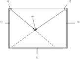
如图1所示,是现有技术中单点触控定位的原理示意图。As shown in FIG. 1 , it is a schematic diagram of the principle of single-touch positioning in the prior art.
在触控屏两个角端11、12的位置各放置一个LED(Light Emitting Diode,发光二极管)及摄像头,LED的发散角度为90度或以上,摄像头的拍摄角度为90度或以上;屏幕三边13、14、15放置回归反射条,其作用是可以将光朝着原来的方向反射回去。当屏幕中有触控点(即任意的遮光物体)时,摄像头会拍摄到光场发生变化,根据此光场的变化可计算出触控点所在的角度;通过两个摄像头则可确定触控点在屏幕的位置。Place an LED (Light Emitting Diode, light-emitting diode) and a camera at the positions of the two
这种定位方式中,需要确定触控点10与屏幕边缘的夹角,根据此夹角从两个摄像头处各自引出一条射线,从两摄像头处引出的两条射线的交点即为触控点所在的位置。In this positioning method, the angle between the
依照上述原理,本发明实施例光学触控定位系统及方法,设置四个摄像头进行拍摄光场分布,利用四个摄像头得到的图像确定触控点的坐标,从而实现多点触控定位。According to the above principles, the optical touch positioning system and method of the embodiment of the present invention set four cameras to capture the light field distribution, and use the images obtained by the four cameras to determine the coordinates of the touch points, thereby realizing multi-touch positioning.
如图2所示,是本发明实施例光学触控定位系统的结构示意图。As shown in FIG. 2 , it is a schematic structural diagram of an optical touch positioning system according to an embodiment of the present invention.
该系统可以对触控屏上的一个或多个触控点进行定位,如图2中触控屏200上的两上触控点P1和P2。The system can locate one or more touch points on the touch screen, such as two touch points P1 and P2 on the
该系统包括:至少四个依次设置在触控屏200一侧边缘不同位置的摄像头,以及图像处理器300。其中,所述摄像头用于拍摄触控屏200上所述摄像头视场区域的图像,并且所述至少四个摄像头形成的视场区域需要覆盖触控屏200的所有区域;图像处理器300用于利用各摄像头拍摄的图像对触控屏200上的触控点进行定位。The system includes: at least four cameras sequentially arranged at different positions on one edge of the
在图2中示出了四个摄像头的情况,分别如图中所示的摄像头201、202、203和204,这些摄像头用于拍摄所述触控屏上所述摄像头视场区域的图像。FIG. 2 shows the situation of four cameras, respectively
当然,在有两个以上触控点的情况,还可以增加摄像头的数量,以实现准确定位,本发明实施例不做限定。为了描述方便,下面以四个摄像头的情况为例进行说明。Of course, if there are more than two touch points, the number of cameras can also be increased to achieve accurate positioning, which is not limited in this embodiment of the present invention. For the convenience of description, a case of four cameras is taken as an example for description below.
上述四个摄像头用于拍摄触控屏上摄像头视场区域的图像,包括无遮光物体(即触控物体)时的图像和有遮光物体时的图像,以便图像处理器300根据这两种图像获取包含触控点的图像信息。The above four cameras are used to capture images of the field of view of the camera on the touch screen, including images without shading objects (i.e., touch objects) and images with shading objects, so that the
上述四个摄像头可以任意设置在触控屏200一侧边缘的不同位置上,只要使上述四个摄像头形成的视场区域能够覆盖到整个触控屏200即可,因此,各摄像头可以采用视场角大于等于90度的线阵摄像头,相对于现有技术中面阵摄像头,大大降低了设备成本。而且,从电学角度来说,线阵摄像头的图像处理复杂度及处理时间都大大优于面阵摄像头,可以提高系统处理效率;从结构角度来说,线阵摄像头的大小大约仅有3mm高,体积小,便于集成,尤其适用于各种体积较小的电子设备。The above four cameras can be arbitrarily arranged at different positions on one side edge of the
在实际应用中,为了方便图像处理器300对各摄像头拍摄图像的处理,简化运算量,可以使第一摄像头201和第三摄像头203形成的视场区域与第二摄像头202和第四摄像头204形成的视场区域有部分重叠。比如,图2中的四个摄像头可以按照以下方式来设置:In practical applications, in order to facilitate the
第一摄像头201和第四摄像头204设置在一侧边缘的两端,第二摄像头202和第三摄像头203设置在中间,比如,上述一侧边缘的长度为L,则第二摄像头202和第三摄像头203可分别设置在距离第一摄像头201为L/3和2L/3的位置。The
当然,上述设置方式只是一种举例,具体还可以有其它设置方式,对此本发明实施例不做限定。Of course, the above setting manner is only an example, and there may be other setting manners, which are not limited in this embodiment of the present invention.
需要说明的是,上述触控屏200可以应用于各种类型的电子显示系统,其形状可以是矩形显示屏,如图2中所示,当然,也可以是其它形状。It should be noted that the above-mentioned
另外,在实际应用中,与现有技术类似,需要在触控区域上方放置红外光源如LED,以照射整个触控区域。在图2中示出了将红外光源安装在LED灯板212上的情况。在触控屏200除安装摄像头的一侧之外的其它三个边缘放置对红外的吸光材料。In addition, in practical applications, similar to the prior art, it is necessary to place an infrared light source such as an LED above the touch area to illuminate the entire touch area. FIG. 2 shows the situation of installing the infrared light source on the
当无触控物体时,各摄像头拍摄到的是一片暗场,当触控屏200上出现了触控物体时,由于触控物体具有漫反射效果,使得照射到触控物体的红外光反射到摄像头并被其探测到,从而引起摄像头所对应像素探测到的光强发生变化,根据光强的变化,即可确定触控点与触控区域边沿的夹角,如图2中的角度β。When there is no touch object, each camera captures a dark field. When a touch object appears on the
需要说明的是,本发明实施例光学触控定位系统并不限于上述暗场拍摄的环境,也可以应用于亮场环境,比如,在触控屏200除安装摄像头的一侧之外的其它三个边缘放置回归反射条,摄像头探测从摄像头处发射到回归反射条中反射回来的光,当有触控物体时,摄像头探测至的光会被遮挡,从而可以得到触控物体的坐标。It should be noted that the optical touch positioning system in the embodiment of the present invention is not limited to the above-mentioned dark-field shooting environment, and can also be applied in a bright-field environment. A retro-reflective strip is placed on each edge, and the camera detects the light emitted from the camera to the retro-reflective strip. When an object is touched, the light detected by the camera will be blocked, so that the coordinates of the touched object can be obtained.
对于有两个触控点的情况,由于两个摄像头可以探测到四个触控点,其中两个为鬼点,如图3所示,两个摄像头31和32会探测到四个触控点A、B、C、D,其中,A、B为真触控点,而C、D为鬼点。For the situation with two touch points, since two cameras can detect four touch points, two of which are ghost points, as shown in Figure 3, two cameras 31 and 32 will detect four touch points A, B, C, D, where A, B are real touch points, and C, D are ghost points.
针对这种情况,本发明实施例的系统中的图像处理器300,可以在触控区域中出现两点的触控物体时,使每个触控物体都会被三个或以上的摄像头探测到,因此可以将每两个摄像头为一组,根据其光场变化可得出四个点,取两组摄像头得出的值对比则可去掉鬼点得出真正的触控点。In view of this situation, the
如图2所示,上述图像处理器300包括:信息获取模块301、触控点区域确定单元302和触控点定位单元303。其中:As shown in FIG. 2 , the
信息获取模块301,用于提取各摄像头拍摄的图像中包含触控点的图像信息,并根据所述图像信息确定对应各摄像头的拍摄角度信息;An
触控点区域确定模块302,用于根据信息获取模块301确定的对应各摄像头的拍摄角度信息确定触控点所在区域;The touch point
触控点定位模块303,用于根据触控点区域确定模块302确定的触控点所在区域,选取信息获取模块301确定的对应不同摄像头的拍摄角度信息进行组合,并根据组合结果确定触控点的位置。The touch
需要说明的是,上述拍摄角度是指触控物体在每个摄像头的视场区域内的相对角度,它可以采用多种不同的定义方式,比如:触控物体与一个摄像头的连线与触控屏一侧边界的夹角,如图2中的角度β;或者触控物体与两个摄像头之间的连线的夹角等。对于不同的坐标系,可以选择不同的拍摄角度定义,以使计算更简单。It should be noted that the above-mentioned shooting angle refers to the relative angle of the touch object in the field of view of each camera, which can be defined in many different ways, such as: the connection between the touch object and a camera and the touch The included angle of the border on one side of the screen, such as the angle β in Figure 2; or the included angle of the line between the touch object and the two cameras, etc. For different coordinate systems, different camera angle definitions can be chosen to make calculations easier.
上述触控点定位模块303根据触控点所在区域,选取对应不同摄像头的拍摄角度信息进行组合,并根据组合结果确定触控点的位置的详细过程将在后面详细描述。The touch
本发明实施例的系统中的图像处理器300,可以简单、方便地实现对多个触控点的定位,当然,对于有一个触控点的情况同样也适用。The
在单点触控的情况下,由于每个摄像头只是拍摄到一个触控点,因此,为了进一步兼容并简化这种情况下的计算过程,在本发明光学触控定位系统的另一实施例中,如图4所示,所述图像处理器400不仅包括:信息获取模块401、触控点区域确定单元402、触控点定位单元403,还可进一步包括:In the case of single touch, since each camera only captures one touch point, in order to be further compatible and simplify the calculation process in this case, in another embodiment of the optical touch positioning system of the present invention , as shown in FIG. 4, the
检查模块404,用于检查信息获取模块401确定的对应各摄像头的拍摄角度信息中是否有多个拍摄角度信息对应一个摄像头。The
相应地,在该实施例中:Accordingly, in this example:
信息获取模块401,用于提取各摄像头拍摄的图像中包含触控点的图像信息,并根据所述图像信息确定对应各摄像头的拍摄角度信息;An information acquisition module 401, configured to extract image information including touch points in images captured by each camera, and determine shooting angle information corresponding to each camera according to the image information;
触控点区域确定模块402,具体用于在检查模块404的检查结果是有多个拍摄角度信息对应一个摄像头时,根据信息获取模块401确定的对应各摄像头的拍摄角度信息确定触控点所在区域;The touch point
触控点定位模块403,还用于在检查模块404的检查结果是没有多个拍摄角度信息对应一个摄像头时,选取信息获取模块401确定的对应不同摄像头的拍摄角度信息中的任意两个拍摄角度信息确定触控点的位置。The touch
也就是说,在该实施例中,图像处理器400在确定对应各摄像头的拍摄角度信息后,需要先检查对应各摄像头的拍摄角度信息中是否有多个拍摄角度信息对应一个摄像头,如果有,表明有多个触控点,则需要先确定触控点所在区域,然后再根据触控点所在区域选取对应不同摄像头的拍摄角度信息进行组合,并根据组合结果确定触控点的位置;如果没有,表明只有单个触控点,则无需对触控点区域进行定位,而是直接从对应不同摄像头的拍摄角度信息中任意选取两个拍摄角度信息即可确定触控点的位置,进一步简化了定位处理过程。That is to say, in this embodiment, after the
相应地,本发明实施例还提供一种光学触控定位方法,用于对触控屏上的一个或多个触控点进行定位。Correspondingly, an embodiment of the present invention also provides an optical touch positioning method for positioning one or more touch points on a touch screen.
如图5所示,是本发明实施例光学触控定位方法的流程图,包括以下步骤:As shown in FIG. 5, it is a flow chart of the optical touch positioning method according to the embodiment of the present invention, including the following steps:
步骤501,通过设置在所述触控屏一侧边缘不同位置的至少四个摄像头拍摄所述触控屏上所述摄像头视场区域的图像。
步骤502,提取各摄像头拍摄的图像中包含触控点的图像信息,并根据所述图像信息确定对应各摄像头的拍摄角度信息。
前面提到,在无触控物体时,摄像头拍摄到的是一片暗场,当触控屏上出现了触控物体时,由于触控物体具有漫反射效果,使得照射到触控物体的红外光反射到摄像头并被其探测到,从而引起摄像头所对应像素探测到的光强发生变化,根据光强的变化,即可从各摄像头拍摄的图像中提取出包含触控点的图像信息,进而可以根据这些图像信息确定对应各摄像头的拍摄角度信息。As mentioned earlier, when there is no touch object, the camera captures a dark field. When a touch object appears on the touch screen, due to the diffuse reflection effect of the touch object, the infrared light irradiated on the touch object Reflected to the camera and detected by it, the light intensity detected by the corresponding pixel of the camera changes. According to the change of light intensity, the image information including the touch point can be extracted from the image captured by each camera, and then can be The shooting angle information corresponding to each camera is determined according to the image information.
所述拍摄角度是指触控物体在每个摄像头的视场区域内的相对角度,它可以采用多种不同的定义方式,具体可参照前面的描述,在此不再赘述。The shooting angle refers to the relative angle of the touch object within the field of view of each camera, which can be defined in many different ways. For details, please refer to the previous description, which will not be repeated here.
步骤503,根据对应各摄像头的拍摄角度信息确定触控点所在区域。
步骤504,根据所述触控点所在区域,选取所述对应不同摄像头的拍摄角度信息进行组合,并根据组合结果确定触控点的位置。
在实际应用中,上述四个摄像头可以任意设置在触控屏一侧边缘的不同位置上,只要使上述四个摄像头形成的视场区域能够覆盖到整个触控屏即可,因此,各摄像头可以采用视场角大于等于90度的线阵摄像头,相对于现有技术中面阵摄像头,大大降低了设备成本。而且,从电学角度来说,线阵摄像头的图像处理复杂度及处理时间都大大优于面阵摄像头,可以提高系统处理效率;从结构角度来说,线阵摄像头的大小大约仅有3mm高,体积小,便于集成,尤其适用于各种体积较小的电子设备。利用本发明实施例的方法,可以有效提高定位精度并减少识别运算量。In practical applications, the above four cameras can be arbitrarily arranged at different positions on one edge of the touch screen, as long as the field of view formed by the above four cameras can cover the entire touch screen. Therefore, each camera can Compared with the area array camera in the prior art, the equipment cost is greatly reduced by adopting a line array camera with a field of view greater than or equal to 90 degrees. Moreover, from an electrical point of view, the image processing complexity and processing time of the line array camera are much better than that of the area array camera, which can improve the system processing efficiency; from the structural point of view, the size of the line array camera is only about 3mm high. Small size, easy to integrate, especially suitable for various electronic devices with small volume. By using the method in the embodiment of the present invention, the positioning accuracy can be effectively improved and the recognition calculation amount can be reduced.
需要说明的是,针对只有一个触控点的情况,同样可以按照上述流程确定触控点的位置。但是在单点触控的情况下,由于每个摄像头只是拍摄到一个触控点,因此,为了进一步兼容并简化这种情况下的计算过程,本发明实施例光学触控定位方法的另一种流程如图6所示,包括以下步骤:It should be noted that, for the case of only one touch point, the position of the touch point can also be determined according to the above process. However, in the case of single-touch, since each camera only captures one touch point, in order to be further compatible and simplify the calculation process in this case, another optical touch positioning method in the embodiment of the present invention The process is shown in Figure 6, including the following steps:
步骤601,通过设置在所述触控屏一侧边缘不同位置的至少四个摄像头拍摄所述触控屏上所述摄像头视场区域的图像。Step 601 , using at least four cameras arranged at different positions on one edge of the touch screen to capture images of the field of view area of the camera on the touch screen.
步骤602,提取各摄像头拍摄的图像中包含触控点的图像信息,并根据所述图像信息确定对应各摄像头的拍摄角度信息。Step 602, extract image information including touch points from images captured by each camera, and determine shooting angle information corresponding to each camera according to the image information.
步骤603,检查对应各摄像头的拍摄角度信息中是否有多个拍摄角度信息对应一个摄像头;如果是,则执行步骤604;否则,执行步骤606。Step 603 , check whether there is multiple shooting angle information corresponding to one camera in the shooting angle information corresponding to each camera; if yes, go to step 604 ; otherwise, go to step 606 .
步骤604,根据对应各摄像头的拍摄角度信息确定触控点所在区域。Step 604: Determine the area where the touch point is located according to the shooting angle information corresponding to each camera.
步骤605,根据所述触控点所在区域,选取所述对应不同摄像头的拍摄角度信息进行组合,并根据组合结果确定触控点的位置。Step 605 , according to the area where the touch point is located, select and combine the shooting angle information corresponding to different cameras, and determine the position of the touch point according to the combination result.
步骤606,选取所述对应不同摄像头的拍摄角度信息中的任意两个拍摄角度信息确定触控点的位置。Step 606, selecting any two shooting angle information in the shooting angle information corresponding to different cameras to determine the position of the touch point.
需要说明的是,上述拍摄角度是指触控物体在每个摄像头的视场区域内的相对角度,它可以采用多种不同的定义方式,比如:触控物体与一个摄像头的连线与触控屏一侧边界的夹角,如图2中的角度β;或者触控物体与两个摄像头之间的连线的夹角等。对于不同的坐标系,可以选择不同的拍摄角度定义,以使计算更简单。比如,将拍摄角度定义为:触控物体与一个摄像头的连线与触控屏一侧边界的夹角,则可以按以下方式确定对应各摄像头的拍摄角度信息:It should be noted that the above-mentioned shooting angle refers to the relative angle of the touch object in the field of view of each camera, which can be defined in many different ways, such as: the connection between the touch object and a camera and the touch The included angle of the border on one side of the screen, such as the angle β in Figure 2; or the included angle of the line between the touch object and the two cameras, etc. For different coordinate systems, different camera angle definitions can be chosen to make calculations easier. For example, if the shooting angle is defined as the angle between the line connecting the touch object and a camera and the border on one side of the touch screen, the shooting angle information corresponding to each camera can be determined as follows:
如图7所示,由于摄像头的视场角大于等于90度,相当于摄像头的每一个像素等分了其视场角。假如摄像头的像素为512,其视场角为90度,每个像素所占的角度为90度/512。如图7所示,当屏幕中存在一个触控点,那么两个角端的摄像头可以拍摄到其图像的变化。根据图像的变化可得出哪个像素所在的角度存在触控点。假如得出的触控点像素值的变化量为n,则θ可Φ的值可以根据公式n*90度/512算出。As shown in FIG. 7 , since the field of view of the camera is greater than or equal to 90 degrees, it means that each pixel of the camera equally divides its field of view. If the camera has 512 pixels and its field of view is 90 degrees, the angle occupied by each pixel is 90 degrees/512. As shown in FIG. 7 , when there is a touch point on the screen, the cameras at the two corners can capture changes in its image. According to the change of the image, it can be obtained which pixel has a touch point at an angle. Assuming that the obtained variation of the pixel value of the touch point is n, the value of θ or Φ can be calculated according to the formula n*90°/512.
相应地,可以将触屏区域定义为一个坐标图,A点为坐标原点(0,0),触控区域的H和L为触控区域的长和宽,此值可实际测量得到。根据上面得到的拍摄角度θ和Φ,则求出x,y的值,从而得到触控点的坐标值(x,y)。Correspondingly, the touch screen area can be defined as a coordinate map, point A is the coordinate origin (0, 0), and H and L of the touch area are the length and width of the touch area, which can be obtained by actual measurement. According to the shooting angles θ and Φ obtained above, the values of x and y are obtained, so as to obtain the coordinate values (x, y) of the touch point.
下面以四个摄像头的情况为例,对本发明实施例光学触控定位方法中对两个触控点进行定位的过程做进一步详细说明。Taking the case of four cameras as an example, the process of locating two touch points in the optical touch locating method according to the embodiment of the present invention will be further described in detail below.
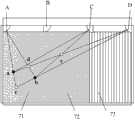
如图8所示,四个摄像头的位置如下:As shown in Figure 8, the positions of the four cameras are as follows:
摄像头A、B、C、D等距离的设置在触控屏的一侧,摄像头A、D作为主摄像头设置在两端,摄像头B、C作为辅助摄像头设置在中间。假设触控屏为矩形,设置摄像头的一侧长度为L,则四个摄像头将触控屏等分为三个视场区域,如图8中所示的区域71、72、73。Cameras A, B, C, and D are equidistantly arranged on one side of the touch screen, cameras A and D are arranged at both ends as main cameras, and cameras B and C are arranged in the middle as auxiliary cameras. Assuming that the touch screen is rectangular, and the length of one side of the camera is set to be L, the four cameras divide the touch screen into three viewing areas equally, such as
为了根据每个摄像头拍摄的图像信息方便计算触控点的位置,在本发明实施例中,可以触控屏所在的平面建立坐标系。具体地,可以触控屏所在的平面内的任何一点作为坐标原点,建立坐标系。比如,以摄像头A为坐标原点,建立直角坐标系,则摄像头A的坐标为(0,0),摄像头B的坐标为(L/3,0),摄像头C的坐标为(2L/3,0),摄像头D的坐标为(L,0)。In order to conveniently calculate the position of the touch point according to the image information captured by each camera, in the embodiment of the present invention, a coordinate system may be established on the plane where the touch screen is located. Specifically, any point in the plane where the touch screen is located can be used as the coordinate origin to establish a coordinate system. For example, if camera A is used as the coordinate origin and a Cartesian coordinate system is established, the coordinates of camera A are (0, 0), the coordinates of camera B are (L/3, 0), and the coordinates of camera C are (2L/3, 0 ), the coordinates of camera D are (L, 0).
触控点a和c的坐标为未知,分别设为(x1,y1)和(x2,y2)。The coordinates of touch points a and c are unknown, and are set to (x1, y1) and (x2, y2) respectively.
在该实施例中,将拍摄角度定义为:触控物体与一个摄像头的连线与触控屏一侧边界的夹角。In this embodiment, the shooting angle is defined as: the angle between the line connecting the touch object and a camera and the border on one side of the touch screen.
拍摄角度信息的获取可以通过在触控屏边缘设置颜色线的方式,即根据摄像头拍摄到的有触控物体时的颜色线图案与无触控物体时的颜色线图案对比,获取对应各摄像头的拍摄角度信息。当然,也可以其它类似的方式或本领域公知的技术获取对应各摄像头的拍摄角度信息。对此,本发明实施例不做限定。The shooting angle information can be obtained by setting the color line on the edge of the touch screen, that is, according to the comparison of the color line pattern when there is a touch object captured by the camera and the color line pattern when there is no touch object, to obtain the corresponding camera. Camera angle information. Certainly, the shooting angle information corresponding to each camera may also be acquired in other similar manners or techniques known in the art. In this regard, the embodiment of the present invention does not make a limitation.
如果对应每个摄像头的拍摄角度信息只有一个,则表明只有一个触控点,即单点触控,在这种情况下,可以任意选取其中的两个摄像头对应的角度信息即可确定触控点的位置,具体过程与现有技术中单点控触定位的过程类似,在此不再赘述。If there is only one shooting angle information corresponding to each camera, it means that there is only one touch point, that is, single-touch. In this case, the angle information corresponding to two cameras can be arbitrarily selected to determine the touch point The specific process is similar to the single-touch positioning process in the prior art, and will not be repeated here.
如果对应某个摄像头的拍摄角度信息有多个,则表明有多个触控点,在这种情况下,需要根据所述拍摄角度信息确定触控点所在区域,并根据所述触控点所在区域,选取所述对应不同摄像头的拍摄角度信息进行组合,根据组合结果确定触控点的位置。If there are multiple shooting angle information corresponding to a certain camera, it indicates that there are multiple touch points. In this case, it is necessary to determine the area where the touch point is located according to the shooting angle information, and area, select the shooting angle information corresponding to different cameras to combine, and determine the position of the touch point according to the combination result.
如图8所示,具体有以下几种情况:As shown in Figure 8, the specific situations are as follows:
(1)摄像头A、D对应的拍摄角度信息分别有两个,而摄像头B、C对应的拍摄角度信息均只有一个,则可确定触控点的位置为一个在区域71,另一个在区域73,如图8所示。(1) There are two shooting angle information corresponding to cameras A and D, and only one shooting angle information corresponding to cameras B and C, so it can be determined that one touch point is in
在这种情况下,选取摄像头A、D对应的拍摄角度信息进行计算可得出a,b,c,d四个交点,根据区域限制可确定点a,c为实际触控点,有效减少了运算过程。In this case, the four intersection points a, b, c, and d can be obtained by selecting the shooting angle information corresponding to cameras A and D for calculation. According to the area limit, points a and c can be determined as actual touch points, which effectively reduces the operation process.
(2)摄像头A、C、D对应的拍摄角度信息分别有两个,摄像头B对应的拍摄角度信息只有一个,则可确定触控点的位置一个在区域71,另一个在区域72,如图9所示。(2) There are two shooting angle information corresponding to cameras A, C, and D, and only one shooting angle information corresponding to camera B, so it can be determined that one of the touch points is in
在这种情况下,选取根据摄像头A、D对应的拍摄角度信息进行计算可以得出a,b,c,d四个交点,根据区域限制可以确定点交点a为实际触控点,而且,由于摄像头A、C、D对应的拍摄角度信息分别有两个,则可确定点c也是实际触控点。或者利用反推法,根据两直线相交于一点的原理,由于确定了交点a为实际触控点,如果假设交点d或b为实际触控点,则只能得出三个交点,而实际计算得到的是四个交点,由此也可以确定交点d和b为鬼点,另一个实际触控点为交点c。In this case, four intersection points a, b, c, and d can be obtained by selecting and calculating according to the shooting angle information corresponding to cameras A and D, and the intersection point a can be determined as the actual touch point according to the area limitation, and, because There are two shooting angle information corresponding to cameras A, C, and D respectively, so it can be determined that point c is also an actual touch point. Or use the reverse deduction method, according to the principle that two straight lines intersect at one point, since the intersection point a is determined to be the actual touch point, if it is assumed that the intersection point d or b is the actual touch point, only three intersection points can be obtained, and the actual calculation Four intersection points are obtained, so it can also be determined that intersection points d and b are ghost points, and another actual touch point is intersection point c.
(3)摄像头A、B、D对应的拍摄角度信息分别有两个,摄像头C对应的拍摄角度信息只有一个,则确定触控点所在区域、以及根据触控点所在区域,选取对应不同摄像头的拍摄角度信息进行组合,根据组合结果确定触控点的位置的过程与上述第(2)种情况类似,在此不再详细描述。(3) There are two shooting angle information corresponding to cameras A, B, and D, and only one shooting angle information corresponding to camera C, then determine the area where the touch point is located, and select the corresponding to different cameras according to the area where the touch point is located. The process of combining shooting angle information and determining the position of the touch point according to the combination result is similar to the above-mentioned case (2), and will not be described in detail here.
(4)摄像头A、C、D对应的拍摄角度信息分别有两个,摄像头B没有对应的拍摄角度信息,则可确定两个触控点皆在区域71中,如图10所示。(4) There are two shooting angle information corresponding to cameras A, C, and D, and there is no corresponding shooting angle information for camera B, so it can be determined that both touch points are in the
在这种情况下,选取摄像头C、D对应的拍摄角度信息进行计算,可以算出a,b,e三个交点,根据区域限制可以剔除鬼点e,得到实际触控点a,b。In this case, the shooting angle information corresponding to cameras C and D is selected for calculation, and the three intersection points a, b, and e can be calculated. According to the area limitation, the ghost point e can be eliminated to obtain the actual touch points a, b.
(5)摄像头A、B、D对应的拍摄角度信息分别有两个,摄像头C没有对应的拍摄角度信息,则可确定两个触控点皆在区域73中。(5) There are two shooting angle information corresponding to cameras A, B, and D respectively, and there is no corresponding shooting angle information for camera C, then it can be determined that both touch points are in the
在这种情况下,根据触控点所在区域,选取对应不同摄像头的拍摄角度信息进行组合,根据组合结果确定触控点的位置的过程与上述第(4)种情况类似,在此不再详细描述。In this case, according to the area where the touch point is located, the shooting angle information corresponding to different cameras is selected for combination, and the process of determining the position of the touch point according to the combination result is similar to the above case (4), and will not be detailed here. describe.
(6)摄像头A、B、C、D对应的拍摄角度信息分别有两个,则可以确定两个触控点皆在区域72中,如图11所示。(6) There are two shooting angle information corresponding to the cameras A, B, C, and D respectively, so it can be determined that both touch points are in the
在这种情况下,仅通过两个摄像头对应的拍摄角度信息无法准确定位触控点,所以可以先根据摄像头A、D对应的拍摄角度信息计算得出a,b,c,d四个交点,再根据摄像头B、C对应的拍摄角度信息计算得出a,b,e,f四个点,根据两者的共同值即可确定出实际的触控点a,b。In this case, the touch point cannot be accurately located only through the shooting angle information corresponding to the two cameras, so the four intersection points a, b, c, and d can be calculated based on the shooting angle information corresponding to cameras A and D. The four points a, b, e, and f are calculated according to the shooting angle information corresponding to cameras B and C, and the actual touch points a, b can be determined according to the common values of the two.
另外,需要说明的是,在根据对应不同摄像头的拍摄角度信息进行计算时,可能会得到触控屏之外的交点,对这样的交点,可根据触控屏的坐标直接排除。In addition, it should be noted that when calculating according to the shooting angle information corresponding to different cameras, intersection points other than the touch screen may be obtained, and such intersection points can be directly excluded according to the coordinates of the touch screen.
本发明实施例提供的光学触控定位方法,通过设置在所述触控屏一侧边缘不同位置的至少四个摄像头拍摄所述触控屏上所述摄像头视场区域的图像;提取各摄像头拍摄的图像中包含触控点的图像信息,并根据所述图像信息确定对应各摄像头的拍摄角度信息;根据所述拍摄角度信息确定触控点所在区域;根据所述触控点所在区域,选取所述对应不同摄像头的拍摄角度信息进行组合,并根据组合结果确定触控点的位置。上述四个摄像头可以任意设置在触控屏一侧边缘的不同位置上,只要使上述四个摄像头形成的视场区域能够覆盖到整个触控屏即可,因此,各摄像头可以采用视场角大于等于90度的线阵摄像头,相对于现有技术中面阵摄像头,可以提高系统处理效率,集成度高,尤其适用于各种体积较小的电子设备。利用本发明实施例的方法,将触控点所在区域判定与对应不同摄像头的拍摄角度信息的组合相结合,可以有效提高定位精度并减少识别运算量。In the optical touch positioning method provided by the embodiment of the present invention, at least four cameras arranged at different positions on one side of the touch screen are used to capture images of the field of view area of the camera on the touch screen; The image of the touch point is contained in the image information of the touch point, and the shooting angle information corresponding to each camera is determined according to the image information; the area where the touch point is located is determined according to the shooting angle information; the area where the touch point is located is selected according to the area where the touch point is located Combining the above shooting angle information corresponding to different cameras, and determining the position of the touch point according to the combination result. The above four cameras can be arbitrarily arranged at different positions on one edge of the touch screen, as long as the field of view formed by the above four cameras can cover the entire touch screen. Therefore, each camera can adopt a field of view angle larger than Compared with the area array camera in the prior art, the line array camera equal to 90 degrees can improve the processing efficiency of the system and has a high degree of integration, and is especially suitable for various electronic devices with small volume. By using the method of the embodiment of the present invention, the determination of the area where the touch point is located is combined with the combination of shooting angle information corresponding to different cameras, which can effectively improve the positioning accuracy and reduce the amount of recognition calculation.
本说明书中的各个实施例均采用递进的方式描述,各个实施例之间相同相似的部分互相参见即可,每个实施例重点说明的都是与其他实施例的不同之处。以上所描述的系统实施例仅仅是示意性的,其中所述作为分离部件说明的模块可以是或者也可以不是物理上分开的。可以根据实际的需要选择其中的部分或者全部模块来实现本实施例方案的目的。本领域普通技术人员在不付出创造性劳动的情况下,即可以理解并实施。Each embodiment in this specification is described in a progressive manner, the same and similar parts of each embodiment can be referred to each other, and each embodiment focuses on the differences from other embodiments. The system embodiments described above are merely illustrative, and the modules described as separate components may or may not be physically separate. Part or all of the modules can be selected according to actual needs to achieve the purpose of the solution of this embodiment. It can be understood and implemented by those skilled in the art without creative effort.
以上对本发明实施例进行了详细介绍,本文中应用了具体实施方式对本发明进行了阐述,以上实施例的说明只是用于帮助理解本发明的方法及设备;同时,对于本领域的一般技术人员,依据本发明的思想,在具体实施方式及应用范围上均会有改变之处,综上所述,本说明书内容不应理解为对本发明的限制。The embodiments of the present invention have been described in detail above, and the present invention has been described using specific implementation methods herein. The descriptions of the above embodiments are only used to help understand the method and equipment of the present invention; meanwhile, for those of ordinary skill in the art, According to the idea of the present invention, there will be changes in the specific implementation and scope of application. To sum up, the contents of this specification should not be construed as limiting the present invention.
Claims (10)
Translated fromChinesePriority Applications (1)
| Application Number | Priority Date | Filing Date | Title |
|---|---|---|---|
| CN201110278463.0ACN102364418B (en) | 2011-09-19 | 2011-09-19 | Optical touch-control positioning system and method |
Applications Claiming Priority (1)
| Application Number | Priority Date | Filing Date | Title |
|---|---|---|---|
| CN201110278463.0ACN102364418B (en) | 2011-09-19 | 2011-09-19 | Optical touch-control positioning system and method |
Publications (2)
| Publication Number | Publication Date |
|---|---|
| CN102364418Atrue CN102364418A (en) | 2012-02-29 |
| CN102364418B CN102364418B (en) | 2014-07-02 |
Family
ID=45690984
Family Applications (1)
| Application Number | Title | Priority Date | Filing Date |
|---|---|---|---|
| CN201110278463.0AExpired - Fee RelatedCN102364418B (en) | 2011-09-19 | 2011-09-19 | Optical touch-control positioning system and method |
Country Status (1)
| Country | Link |
|---|---|
| CN (1) | CN102364418B (en) |
Cited By (1)
| Publication number | Priority date | Publication date | Assignee | Title |
|---|---|---|---|---|
| TWI464653B (en)* | 2012-08-10 | 2014-12-11 | Pixart Imaging Inc | Optical touch system and optical touch contorl method |
Citations (3)
| Publication number | Priority date | Publication date | Assignee | Title |
|---|---|---|---|---|
| CN101354624A (en)* | 2008-05-15 | 2009-01-28 | 中国人民解放军国防科学技术大学 | A surface computing platform and multi-touch detection method with four-way cameras working together |
| CN101566898A (en)* | 2009-06-03 | 2009-10-28 | 广东威创视讯科技股份有限公司 | Positioning device of electronic display system and method |
| CN201622551U (en)* | 2010-03-12 | 2010-11-03 | 北京汇冠新技术股份有限公司 | Large-size optical touch screen |
- 2011
- 2011-09-19CNCN201110278463.0Apatent/CN102364418B/ennot_activeExpired - Fee Related
Patent Citations (3)
| Publication number | Priority date | Publication date | Assignee | Title |
|---|---|---|---|---|
| CN101354624A (en)* | 2008-05-15 | 2009-01-28 | 中国人民解放军国防科学技术大学 | A surface computing platform and multi-touch detection method with four-way cameras working together |
| CN101566898A (en)* | 2009-06-03 | 2009-10-28 | 广东威创视讯科技股份有限公司 | Positioning device of electronic display system and method |
| CN201622551U (en)* | 2010-03-12 | 2010-11-03 | 北京汇冠新技术股份有限公司 | Large-size optical touch screen |
Cited By (2)
| Publication number | Priority date | Publication date | Assignee | Title |
|---|---|---|---|---|
| TWI464653B (en)* | 2012-08-10 | 2014-12-11 | Pixart Imaging Inc | Optical touch system and optical touch contorl method |
| US9207809B2 (en) | 2012-08-10 | 2015-12-08 | Pixart Imaging Inc. | Optical touch system and optical touch control method |
Also Published As
| Publication number | Publication date |
|---|---|
| CN102364418B (en) | 2014-07-02 |
Similar Documents
| Publication | Publication Date | Title |
|---|---|---|
| US10324563B2 (en) | Identifying a target touch region of a touch-sensitive surface based on an image | |
| US9454260B2 (en) | System and method for enabling multi-display input | |
| CN102654809B (en) | Optical image type touch device | |
| US8614694B2 (en) | Touch screen system based on image recognition | |
| EP2302491A2 (en) | Optical touch system and method | |
| US8269750B2 (en) | Optical position input system and method | |
| US20130038577A1 (en) | Optical touch device and coordinate detection method thereof | |
| TW201113786A (en) | Touch sensor apparatus and touch point detection method | |
| CN104461176A (en) | Information processor, processing method, and projection system | |
| CN102968218B (en) | Optical image type touch device and touch image processing method | |
| CN101833401B (en) | Optical touch display device and operating method thereof | |
| US10037107B2 (en) | Optical touch device and sensing method thereof | |
| US9323346B2 (en) | Accurate 3D finger tracking with a single camera | |
| Walker | Camera‐based optical touch technology | |
| CN102622140B (en) | Image pick-up multi-point touch system | |
| US9489077B2 (en) | Optical touch panel system, optical sensing module, and operation method thereof | |
| TW201222365A (en) | Optical screen touch system and method thereof | |
| US20130016069A1 (en) | Optical imaging device and imaging processing method for optical imaging device | |
| US20150193085A1 (en) | Object tracking system and method | |
| TWI582672B (en) | An optical touch device and touch detecting method using the same | |
| CN102364418A (en) | An optical touch positioning system and method | |
| CN202443449U (en) | Photographic multi-point touch system | |
| CN105653101B (en) | Touch point sensing method and optical touch system | |
| US9684415B2 (en) | Optical touch-control system utilizing retro-reflective touch-control device | |
| CN102479002B (en) | Optical touch system and sensing method thereof |
Legal Events
| Date | Code | Title | Description |
|---|---|---|---|
| C06 | Publication | ||
| PB01 | Publication | ||
| C10 | Entry into substantive examination | ||
| SE01 | Entry into force of request for substantive examination | ||
| C14 | Grant of patent or utility model | ||
| GR01 | Patent grant | ||
| CP03 | Change of name, title or address | ||
| CP03 | Change of name, title or address | Address after:Kezhu road high tech Industrial Development Zone, Guangzhou city of Guangdong Province, No. 233 510670 Patentee after:VTRON GROUP Co.,Ltd. Address before:510663 Guangzhou province high tech Industrial Development Zone, Guangdong, Cai road, No. 6, No. Patentee before:VTRON TECHNOLOGIES Ltd. | |
| TR01 | Transfer of patent right | Effective date of registration:20201125 Address after:226500 Nantong City, Nantong, Jiangsu Province, the city of Rugao City Street Red Star Village (Jiang Jiushan owned house) Patentee after:RUGAO CHIJIU STAINLESS STEEL PIPE FACTORY Address before:Unit 2414-2416, main building, no.371, Wushan Road, Tianhe District, Guangzhou City, Guangdong Province Patentee before:GUANGDONG GAOHANG INTELLECTUAL PROPERTY OPERATION Co.,Ltd. Effective date of registration:20201125 Address after:Unit 2414-2416, main building, no.371, Wushan Road, Tianhe District, Guangzhou City, Guangdong Province Patentee after:GUANGDONG GAOHANG INTELLECTUAL PROPERTY OPERATION Co.,Ltd. Address before:Kezhu road high tech Industrial Development Zone, Guangzhou city of Guangdong Province, No. 233 510670 Patentee before:VTRON GROUP Co.,Ltd. | |
| TR01 | Transfer of patent right | ||
| TR01 | Transfer of patent right | Effective date of registration:20220613 Address after:226500 room 105, block B, No. 528, Huilong South Road, Rucheng street, Rugao City, Nantong City, Jiangsu Province Patentee after:Nantong zhuoxiao Automation Co.,Ltd. Address before:226500 group 4, Hongxing Village, Rucheng street, Rugao City, Nantong City, Jiangsu Province (in the house of Jiang Jiushan) Patentee before:RUGAO CHIJIU STAINLESS STEEL PIPE FACTORY | |
| TR01 | Transfer of patent right | ||
| CF01 | Termination of patent right due to non-payment of annual fee | Granted publication date:20140702 | |
| CF01 | Termination of patent right due to non-payment of annual fee |