CN102361759A - Tape unit and tape cassette - Google Patents
Tape unit and tape cassetteDownload PDFInfo
- Publication number
- CN102361759A CN102361759ACN2010800130999ACN201080013099ACN102361759ACN 102361759 ACN102361759 ACN 102361759ACN 2010800130999 ACN2010800130999 ACN 2010800130999ACN 201080013099 ACN201080013099 ACN 201080013099ACN 102361759 ACN102361759 ACN 102361759A
- Authority
- CN
- China
- Prior art keywords
- mentioned
- tape
- band
- cassette
- wall
- Prior art date
- Legal status (The legal status is an assumption and is not a legal conclusion. Google has not performed a legal analysis and makes no representation as to the accuracy of the status listed.)
- Granted
Links
- 230000005484gravityEffects0.000claimsdescription16
- 230000005540biological transmissionEffects0.000claimsdescription8
- 238000007599dischargingMethods0.000claimsdescription3
- 230000015572biosynthetic processEffects0.000claimsdescription2
- 230000001815facial effectEffects0.000claims1
- 239000003550markerSubstances0.000abstractdescription13
- 238000007639printingMethods0.000description185
- 238000003825pressingMethods0.000description55
- 238000001514detection methodMethods0.000description39
- 238000003860storageMethods0.000description38
- 238000004804windingMethods0.000description32
- 238000003780insertionMethods0.000description24
- 230000037431insertionEffects0.000description24
- 238000009434installationMethods0.000description10
- 230000002093peripheral effectEffects0.000description8
- 238000004519manufacturing processMethods0.000description7
- 238000010586diagramMethods0.000description6
- 238000005259measurementMethods0.000description6
- 230000000149penetrating effectEffects0.000description6
- 238000005520cutting processMethods0.000description5
- 238000000034methodMethods0.000description5
- 230000004323axial lengthEffects0.000description4
- 210000000078clawAnatomy0.000description4
- 238000000926separation methodMethods0.000description4
- 230000007423decreaseEffects0.000description3
- 238000007667floatingMethods0.000description3
- 239000010410layerSubstances0.000description3
- 230000001105regulatory effectEffects0.000description3
- 238000011144upstream manufacturingMethods0.000description3
- 230000033228biological regulationEffects0.000description2
- 230000000994depressogenic effectEffects0.000description2
- 230000006870functionEffects0.000description2
- 239000004973liquid crystal related substanceSubstances0.000description2
- 239000012790adhesive layerSubstances0.000description1
- 238000005452bendingMethods0.000description1
- 239000000470constituentSubstances0.000description1
- 238000006073displacement reactionMethods0.000description1
- 238000003475laminationMethods0.000description1
- 229920003002synthetic resinPolymers0.000description1
- 239000000057synthetic resinSubstances0.000description1
- 238000009823thermal laminationMethods0.000description1
Images


Classifications
- B—PERFORMING OPERATIONS; TRANSPORTING
- B41—PRINTING; LINING MACHINES; TYPEWRITERS; STAMPS
- B41J—TYPEWRITERS; SELECTIVE PRINTING MECHANISMS, i.e. MECHANISMS PRINTING OTHERWISE THAN FROM A FORME; CORRECTION OF TYPOGRAPHICAL ERRORS
- B41J32/00—Ink-ribbon cartridges
- B—PERFORMING OPERATIONS; TRANSPORTING
- B41—PRINTING; LINING MACHINES; TYPEWRITERS; STAMPS
- B41J—TYPEWRITERS; SELECTIVE PRINTING MECHANISMS, i.e. MECHANISMS PRINTING OTHERWISE THAN FROM A FORME; CORRECTION OF TYPOGRAPHICAL ERRORS
- B41J3/00—Typewriters or selective printing or marking mechanisms characterised by the purpose for which they are constructed
- B41J3/407—Typewriters or selective printing or marking mechanisms characterised by the purpose for which they are constructed for marking on special material
- B41J3/4075—Tape printers; Label printers
- B—PERFORMING OPERATIONS; TRANSPORTING
- B41—PRINTING; LINING MACHINES; TYPEWRITERS; STAMPS
- B41J—TYPEWRITERS; SELECTIVE PRINTING MECHANISMS, i.e. MECHANISMS PRINTING OTHERWISE THAN FROM A FORME; CORRECTION OF TYPOGRAPHICAL ERRORS
- B41J11/00—Devices or arrangements of selective printing mechanisms, e.g. ink-jet printers or thermal printers, for supporting or handling copy material in sheet or web form
- B41J11/009—Detecting type of paper, e.g. by automatic reading of a code that is printed on a paper package or on a paper roll or by sensing the grade of translucency of the paper
- B—PERFORMING OPERATIONS; TRANSPORTING
- B41—PRINTING; LINING MACHINES; TYPEWRITERS; STAMPS
- B41J—TYPEWRITERS; SELECTIVE PRINTING MECHANISMS, i.e. MECHANISMS PRINTING OTHERWISE THAN FROM A FORME; CORRECTION OF TYPOGRAPHICAL ERRORS
- B41J15/00—Devices or arrangements of selective printing mechanisms, e.g. ink-jet printers or thermal printers, specially adapted for supporting or handling copy material in continuous form, e.g. webs
- B41J15/04—Supporting, feeding, or guiding devices; Mountings for web rolls or spindles
- B41J15/044—Cassettes or cartridges containing continuous copy material, tape, for setting into printing devices
Landscapes
- Printers Characterized By Their Purpose (AREA)
- Impression-Transfer Materials And Handling Thereof (AREA)
- Handling Of Continuous Sheets Of Paper (AREA)
- Replacement Of Web Rolls (AREA)
Abstract
Translated fromChinese
Description
Translated fromChinese技术领域technical field
本发明涉及一种自由装卸于带打印装置的带盒及带盒中收纳的带单元。The present invention relates to a tape cassette which can be freely loaded and detached in a tape printing device and a tape unit accommodated in the tape cassette.
背景技术Background technique
一直以来,能够在箱状盒壳体的内部对支架上缠绕有带的带单元进行装卸的回填式(所谓“refill type”)带盒已被公知(例如参照专利文献1)。在回填式带盒中,例如带余量变少时、或替换带种类时等情况下,仅更换盒壳体的内部收纳的带单元。通过仅更换带单元,即可再次利用盒壳体。Conventionally, a refill type (so-called "refill type") tape cassette capable of attaching and detaching a tape unit with a tape wound around a holder inside a box-shaped cassette casing is known (for example, refer to Patent Document 1). In a refill type tape cassette, only the tape unit housed inside the cassette case is replaced when, for example, the remaining tape becomes low or when the type of tape is replaced. By replacing only the belt unit, the cartridge case can be reused.
在回填式带盒中,在盒壳体的右后部,设有在上下方向贯通的多个孔部。在带单元的右后部,根据带种类设置多个在上下方向突出的棒状遮蔽部。当带单元收纳在盒壳体内时,多个遮蔽部选择性地嵌入到多个孔部中。在带打印装置的盒安装部,设置总是向上方施力的多个微动开关。当带盒安装到盒安装部时,向下方突出的多个遮蔽部选择性地推压多个微动开关。带打印装置检测多个微动开关中的任意开关被按下、或未被按下,从而确定带的种类。In the refill type tape cassette, a plurality of holes penetrating in the vertical direction are provided at the right rear portion of the cassette case. On the right rear part of the belt unit, a plurality of rod-shaped shielding parts protruding in the up and down direction are provided according to the belt type. When the tape unit is accommodated in the cassette case, the plurality of shielding portions are selectively fitted into the plurality of hole portions. A plurality of microswitches are provided on the cartridge mounting portion of the tape printer to always push upward. The plurality of shielding portions protruding downward selectively press the plurality of micro switches when the tape cassette is attached to the cassette mounting portion. The tape printing device detects whether any of the plurality of micro switches is pressed or not pressed, thereby specifying the type of tape.
专利文献1:日本特开2002-179300号公报Patent Document 1: Japanese Patent Laid-Open No. 2002-179300
在回填式带盒中,例如制造带盒或更换带单元时,与多个遮蔽部所对应的带种类不同的带可能会被错误地收纳到盒壳体内。盒壳体内收纳的带种类与多个遮蔽部不对应时,带打印装置会误测出带的种类。此时,带打印装置在执行打印动作时,可能产生带的打印不良、或传送不良。In the refill type tape cassette, for example, when the tape cassette is manufactured or the tape unit is replaced, tapes of different types corresponding to the plurality of shielding portions may be erroneously accommodated in the cassette case. If the type of tape stored in the cassette case does not correspond to the plurality of shielding parts, the tape printing device may erroneously detect the type of tape. In this case, when the tape printing device executes the printing operation, printing failure or conveyance failure of the tape may occur.
发明内容Contents of the invention
本发明的目的在于提供一种可抑制盒壳体内收纳错误种类的带的带单元及带盒。An object of the present invention is to provide a tape unit and a tape cassette capable of suppressing storage of a wrong type of tape in a cassette case.
本发明的第一方式涉及的带单元,保持缠绕有作为打印介质的带的带辊,装卸于盒壳体中,其中,具有:支架轴部,插入到形成在上述带辊的缠绕中心处的轴孔中,旋转自如地支撑上述带辊;以及标志部,设置在由上述支架轴部支撑的上述带辊的径向外侧,包括至少一个孔部,表示上述带的种类。A tape unit according to a first aspect of the present invention holds a tape roll around which a tape as a printing medium is wound, is attached to and detached from a cassette case, and has a holder shaft inserted into a center formed at the winding center of the tape roll. The tape roll is rotatably supported in a shaft hole; and an indicator portion is provided radially outside of the tape roll supported by the support shaft portion and includes at least one hole portion indicating the type of the tape.
因此,人员通过目视设置在带单元的标志部,可识别出带单元上组装的带的种类、或带单元上应组装的带的种类。进一步,例如在制造带盒或更换带单元时,人员可将组装有正确种类的带的带单元收纳到盒壳体内。因此,可抑制将错误种类的带收纳到盒壳体内。Therefore, a person can recognize the type of tape to be attached to the tape unit or the type of tape to be attached to the tape unit by visually observing the indicator portion provided on the tape unit. Furthermore, for example, when manufacturing a tape cassette or exchanging a tape unit, a person can store the tape unit assembled with the correct type of tape in the cassette case. Therefore, it is possible to suppress a wrong type of tape from being accommodated in the cassette case.
在上述带单元中,可具有引导壁,该引导壁与从上述带辊拉出的上述带的面平行,且沿上述带的传送路径设置,上述标志部设置在上述引导壁上。此时,因在用于引导带的引导壁上设置有标志部,所以带单元无需具备用于设置标志部的专用部件。In the tape unit, a guide wall may be provided that is parallel to a surface of the tape pulled out from the tape roll and provided along a transport path of the tape, and the marker portion may be provided on the guide wall. In this case, since the index portion is provided on the guide wall for guiding the tape, the tape unit does not need to have a dedicated member for providing the index portion.
在上述带单元中,可具有带排出部,该带排出部设置在上述传送路径的下游侧的端部上,并将在上述传送路径上传送的上述带从上述带单元排出;上述引导壁包括下游侧壁部,该下游侧壁部与上述带排出部邻接设置,且沿上述传送路径的最下游侧延伸;上述标志部设置在上述下游侧壁部上。此时,人员可同时目视从带排出部排出的带及设置在下游侧壁部的标志部。In the above-mentioned belt unit, there may be a belt discharge portion provided at an end portion on the downstream side of the above-mentioned conveyance path, and discharge the above-mentioned tape conveyed on the above-mentioned conveyance path from the above-mentioned belt unit; the above-mentioned guide wall includes A downstream side wall portion is provided adjacent to the tape discharge portion and extends along the most downstream side of the conveying path, and the marker portion is provided on the downstream side wall portion. At this time, a person can visually view the tape discharged from the tape discharge part and the indicator part provided on the downstream side wall part at the same time.
在上述带单元中,可具有:路径壁,设置在从上述带辊拉出的上述带的下方,沿上述带的传送路径延伸,且形成上述带单元的底面;下侧凹部,是使上述路径壁的上述底面的一部分向上方凹陷而成的凹部,具有基准面部,该基准面部是与上述底面相比位于上方的平面;以及限制部,设置在上述路径壁的上述传送路径上,在与上述基准面部在上述带单元的上下方向上分离和上述带的宽度对应的距离的位置上,限制上述带向上方移动。此时,在带单元中,限制部的上下方向位置是以基准面部为基准而确定的。因此,可提高制造限制部时的尺寸精度,提高带的传送精度。并且,在制造带单元后,通过以基准面部为基准,限制部的尺寸管理变得容易。In the above-mentioned belt unit, there may be: a path wall provided below the above-mentioned belt pulled out from the above-mentioned belt roller, extending along the conveyance path of the above-mentioned belt, and forming the bottom surface of the above-mentioned belt unit; a lower side recess for making the above-mentioned path A part of the bottom surface of the wall is recessed upward, and has a reference surface that is a plane located above the bottom surface; The reference surface portion restricts upward movement of the belt at a position separated from the belt unit in the vertical direction by a distance corresponding to the width of the belt. At this time, in the belt unit, the vertical position of the restricting portion is determined based on the reference surface. Therefore, the dimensional accuracy at the time of manufacturing the restriction portion can be improved, and the conveyance accuracy of the tape can be improved. In addition, after the belt unit is manufactured, it becomes easy to manage the size of the regulation portion by using the reference surface as a reference.
在上述带单元中,上述基准面部,可在上述带辊被上述支架轴部支撑的状态下,距上述带的宽度方向中心位置在上下方向相隔一定距离地设置。此时,相对基准面部的上下方向位置的带的上下方向位置变得较明确,带的传送精度进一步提高。In the belt unit, the reference surface may be provided at a predetermined distance in the vertical direction from a center position in the width direction of the belt in a state in which the belt roller is supported by the holder shaft. In this case, the vertical position of the tape relative to the vertical position of the reference surface becomes clearer, and the tape conveyance accuracy is further improved.
在上述带单元中,上述中心位置和上述基准面部的上述上下方向上的距离可以不取决于上述带宽度,而是恒定的。此时,即使是分别组装了具有不同带宽度的带的多种带单元,通过以共用的基准面部的位置为基准,可使带单元的尺寸测定、部件管理变得容易。In the belt unit, the vertical distance between the center position and the reference surface may be constant regardless of the belt width. In this case, even if a plurality of types of belt units having different belt widths are separately assembled, the measurement of the size of the belt unit and the management of parts can be facilitated by using the position of the common reference surface as a reference.
在上述带单元中,可具有带排出部,该带排出部设置在上述传送路径的下游侧的端部上,并将在上述传送路径上传送的上述带从上述带单元排出;上述限制部设置在上述带排出部上或其附近。此时,在排出带的带排出部或其附近,限制了带向上方的移动,因此带从带单元的拉出变得稳定。In the above-mentioned belt unit, there may be a belt discharge part provided on the downstream side end of the above-mentioned conveyance path, and discharge the above-mentioned tape conveyed on the above-mentioned conveyance path from the above-mentioned belt unit; On or near the aforementioned tape discharge section. At this time, upward movement of the tape is restricted at or near the tape discharge portion from which the tape is discharged, so that the tape can be pulled out from the tape unit stably.
在上述带单元中,上述下侧凹部可设置在上述路径壁中的上述限制部的附近。此时,下侧凹部和限制部设置在邻接的位置上,因此带单元的尺寸测定、部件管理进一步变得容易。In the belt unit described above, the lower concave portion may be provided in the vicinity of the restricting portion in the path wall. In this case, since the lower concave portion and the restricting portion are provided at adjacent positions, the dimension measurement and parts management of the belt unit are further facilitated.
在上述带单元中,可具有:带传送部,传送从由上述支架轴部支撑的上述带辊拉出的上述带;第一支架开口部,设置在上述支架轴部上,向和上述带辊的轴孔相同的方向开口;第二支架开口部,隔着上述带传送部而设置在和上述第一支架开口部相反的一侧,并向和上述第一支架开口部相同的方向开口。此时,隔着带传送部分别在两侧设置支架开口部。人员可沿着插入到各支架开口部中的引导轴稳定地移动带单元。In the above-mentioned belt unit, it may be provided with: a belt conveying part that conveys the above-mentioned belt pulled out from the above-mentioned belt roller supported by the above-mentioned support shaft part; a first support opening part provided on the above-mentioned support shaft part, and The shaft hole of the second frame is opened in the same direction as the shaft hole; the second frame opening is provided on the opposite side to the first frame opening across the belt conveying portion, and opens in the same direction as the first frame opening. At this time, the holder openings are respectively provided on both sides with the belt conveying portion interposed therebetween. A person can stably move the belt unit along the guide shafts inserted into the openings of the respective holders.
本发明的第二方式涉及的带盒具有:带单元,保持缠绕有作为打印介质的带的带辊;以及盒壳体,装卸有上述带单元;上述带单元具有:支架轴部,插入到形成在上述带辊的缠绕中心的轴孔即辊开口中,并旋转自如地支撑上述带辊;以及标志部,设置在由上述支架轴部支撑的上述带辊的径向外侧,包括至少一个孔部,表示上述带的种类;上述盒壳体具有标志露出部,该标志露出部在上述带单元安装到上述盒壳体内部的状态下使上述标志部露出到上述盒壳体的外部。A tape cassette according to a second aspect of the present invention includes: a tape unit holding a tape roll around which a tape as a printing medium is wound; and a cassette case on which the tape unit is mounted and detached; The above-mentioned tape roll is rotatably supported in the shaft hole of the winding center of the above-mentioned tape roll, that is, the roll opening; and the mark portion is provided on the radially outer side of the above-mentioned tape roll supported by the support shaft portion and includes at least one hole portion. , indicating the type of the tape; the cartridge case has an index exposure portion that exposes the index portion to the outside of the cartridge case when the tape unit is mounted inside the cartridge case.
因此,当带单元安装到盒壳体内部时,设置在带单元的标志部经由盒壳体的标志露出部露出到外部。人员通过目视标志部,可识别出组装到带盒上的带种类、或应组装到带盒上的带种类。即,例如在制造带盒或更换带单元时,人员可将组装了正确种类的带单元收纳到盒壳体内。因此,可抑制错误的种类的带收纳到盒壳体内。Therefore, when the tape unit is mounted inside the cassette case, the index portion provided on the tape unit is exposed to the outside via the index exposure portion of the cassette case. A person can recognize the type of tape to be assembled in the tape cassette or the type of tape to be assembled in the tape cassette by visually identifying the marking portion. That is, for example, when manufacturing a tape cassette or exchanging a tape unit, a person can store a correctly assembled tape unit in the cassette case. Therefore, it is possible to suppress a wrong type of tape from being accommodated in the cassette case.
在上述带盒中,上述盒壳体可具有:壳体侧排出部,用于在上述带单元安装到上述盒壳体内部的状态下,将从上述带辊拉出的上述带从上述盒壳体排出;以及壳体侧引导部,在与上述壳体侧排出部之间形成上述带的露出部位,并引导从上述壳体侧排出部排出的上述带;上述标志露出部设置在和上述带的露出部位邻接的位置。此时,人员可同时目视从壳体侧排出部排出到带的露出部位的带及位于与带的露出部位邻接的位置的标志部。In the above-mentioned tape cassette, the cassette case may have a case-side discharge portion for discharging the tape pulled out from the tape roller from the cassette case in a state in which the tape unit is mounted inside the cassette case. body discharge; and a case side guide part, which forms an exposed portion of the tape between the case side discharge part and the case side discharge part, and guides the above tape discharged from the case side discharge part; The position adjacent to the exposed part. At this time, a person can simultaneously visually view the tape discharged from the case-side discharge portion to the exposed portion of the tape and the indicator portion located adjacent to the exposed portion of the tape.
在上述带盒中,上述带单元可具有带传送部,该带传送部传送从由上述支架轴部支撑的上述带辊拉出的上述带;上述盒壳体具有:底面、前面、背面及一对侧面;以及臂部,包括上述前面的一部分,在上述带单元安装到上述盒壳体内部时,至少收纳上述带传送部中的上述传送路径的下游侧;上述带传送部具有带排出部,该带排出部在上述带单元安装到上述盒壳体内部的状态下将在上述传送路径上传送的上述带排出到上述臂部的内部;上述壳体侧排出部设置在上述臂部上,并将从上述带排出部排出到上述臂部内部的上述带排出到上述盒壳体的外部。此时,在带单元安装到盒壳体内部的状态下,从带辊拉出的带通过带单元传送到臂部。因此,可延长带单元中的带的传送路径,使盒壳体内的带传送稳定。In the above-mentioned tape cassette, the above-mentioned tape unit may have a tape conveying part which conveys the above-mentioned tape pulled out from the above-mentioned tape roller supported by the above-mentioned support shaft part; an opposite side; and an arm portion, including a part of the front face, at least accommodates the downstream side of the above-mentioned conveying path in the above-mentioned tape conveying portion when the above-mentioned tape unit is mounted inside the above-mentioned cassette housing; the above-mentioned tape conveying portion has a tape discharge portion, The tape discharge portion discharges the tape conveyed on the conveyance path to the inside of the arm portion in a state in which the tape unit is mounted inside the cassette case; the case side discharge portion is provided on the arm portion, and The tape discharged from the tape discharge portion into the arm portion is discharged to the outside of the cassette case. At this time, in a state where the tape unit is mounted inside the cassette case, the tape pulled out from the tape roller is conveyed to the arm portion through the tape unit. Therefore, the conveyance path of the tape in the tape unit can be extended, and the tape conveyance in the cassette case can be stabilized.
在上述带盒中,上述带传送部可具有引导部,该引导部与从上述带辊拉出的上述带的面平行,且沿上述传送路径设置;上述引导壁中,在上述带单元安装到上述盒壳体内部的状态下,至少设置有上述标志部的部位与上述前面基本平行;上述标志露出部设置在上述臂部中构成上述前面的一部分的侧壁上。此时,在用于引导带的引导壁上设置标志部,标志部在臂部中从构成前面的一部分的侧壁露出,因此带盒无需用于设置标志部的专用部件。In the above-mentioned tape cassette, the above-mentioned tape conveying part may have a guide part which is parallel to the surface of the above-mentioned tape pulled out from the above-mentioned tape roller and arranged along the above-mentioned conveying path; In the state inside the case, at least the portion where the indicator portion is provided is substantially parallel to the front surface; and the indicator exposed portion is provided on a side wall constituting a part of the front surface of the arm portion. At this time, the guide wall for guiding the tape is provided with a marker portion, and the marker portion is exposed from a side wall constituting a part of the front face in the arm portion, so that the tape cassette does not need a dedicated part for setting the marker portion.
在上述带盒中,上述引导壁可包括下游侧壁部,该下游侧壁部与上述带排出部邻接设置,且沿上述传送路径的最下游侧延伸;上述标志露出部具有和上述下游侧壁部基本一致的形状及大小;上述下游侧壁部,在上述带单元安装到上述盒壳体内部时,嵌入到上述标志露出部而构成上述臂部中的上述侧壁的一部分。此时,当带单元安装到盒壳体的内部时,设置有标志部的下游侧壁部嵌入到标志露出部。这样一来,带单元中的带传送方向的下游侧被固定,因此盒壳体内的带传送变得稳定。In the above tape cassette, the guide wall may include a downstream side wall portion provided adjacent to the tape discharge portion and extending along the most downstream side of the conveyance path; The above-mentioned downstream side wall portion is fitted into the above-mentioned mark exposed portion to constitute a part of the above-mentioned side wall in the above-mentioned arm portion when the above-mentioned belt unit is installed inside the above-mentioned cassette case. At this time, when the tape unit is mounted inside the cassette case, the downstream side wall portion provided with the index portion is fitted into the index exposed portion. In this way, the downstream side of the tape conveyance direction in the tape unit is fixed, so that the tape conveyance in the cassette case becomes stable.
在上述带盒中,上述带单元可具有上述支架轴部设置在一端侧的带支架;上述盒壳体具有:相向配置的呈矩形平面的一对壁面;以及沿着上述一对壁面的周缘部以规定高度形成的侧壁;还具有:第一开口部,设置在上述一对壁面中的至少一个壁面的一个角部;第二开口部,设置在设有上述第一开口部的上述壁面上,并位于上述一个角部的对角上;以及第三开口部,设置在设有上述第一开口部的上述壁面上,并在上述带单元安装到上述盒壳体内部的状态下面向上述辊开口。此时,即使在盒壳体内收纳具有作为重物的带辊的带单元,人员也可沿着分别插入到三个开口部中的三个引导轴稳定地移动带盒。In the above-mentioned tape cassette, the above-mentioned tape unit may have a tape holder in which the above-mentioned holder shaft portion is provided on one end side; the above-mentioned cassette case has: a pair of wall surfaces facing each other and forming a rectangular plane; and a peripheral edge portion along the pair of wall surfaces. A side wall formed at a predetermined height; further comprising: a first opening provided on a corner of at least one of the pair of wall surfaces; a second opening provided on the wall surface on which the first opening is provided , and is located on the opposite corner of the above-mentioned one corner; and the third opening is provided on the above-mentioned wall surface provided with the above-mentioned first opening, and faces the above-mentioned roller under the state that the above-mentioned belt unit is installed in the inside of the above-mentioned cassette case Open your mouth. At this time, even if the tape unit having the tape roller as a weight is accommodated in the cassette case, a person can stably move the tape cassette along the three guide shafts respectively inserted into the three openings.
在上述带盒中,上述带支架在与设有上述支架轴部的一端不同的另一端具有支架开口,该支架开口向和上述辊开口相同的方向开口,上述第一开口部在上述带单元安装到上述盒壳体内部的状态下,面向上述支架开口。此时,引导轴分别插入到带盒的三个开口部中时,在盒壳体内,通过两个引导轴引导带单元两端。这样一来,即使带盒移动时,也可抑制盒壳体内的带单元的振动、倾斜。In the above-mentioned tape cassette, the above-mentioned tape holder has a holder opening at an end different from the end provided with the above-mentioned holder shaft portion, the holder opening is opened in the same direction as the roller opening, and the first opening is attached to the belt unit. In the state of entering the inside of the cartridge case, it faces the opening of the holder. At this time, when the guide shafts are respectively inserted into the three openings of the tape cassette, both ends of the tape unit are guided by the two guide shafts in the cassette case. In this way, even when the tape cassette moves, vibration and inclination of the tape unit in the cassette case can be suppressed.
在上述带盒中,上述带支架可跨越在上述盒壳体内部从上述带辊拉出并传送的上述带的传送路径,并从上述一端向上述另一端延伸。此时,在盒壳体内沿两个引导轴引导的带单元的两端之间,设置带的传送路径。因此,即使带盒移动时,也可抑制对带传送路径的振动、倾斜。In the above-mentioned tape cassette, the tape holder may extend from the one end to the other end across a conveyance path of the tape drawn from the tape roller and conveyed inside the cassette case. At this time, between both ends of the tape unit guided along two guide shafts inside the cassette case, a transport path for the tape is provided. Therefore, even when the tape cassette moves, vibration and inclination to the tape transport path can be suppressed.
在上述带盒中,上述支架轴部在上述带单元安装到上述盒壳体内部的状态下,具有上述第三开口部所面向的轴孔,上述第三开口部具有完全包括上述支架轴部的轴孔的形状及大小,面向上述轴孔整体。此时,第三开口部面向轴孔整体,因此轴孔通过第三开口部露出。因此,即使产生带单元的振动、倾斜,人员也可通过第三开口部将引导轴插入到轴孔内,使作为重物的带辊沿引导轴移动。In the above-mentioned tape cassette, the holder shaft portion has a shaft hole facing the third opening portion when the tape unit is mounted inside the cassette case, and the third opening portion has a shaft hole completely including the holder shaft portion. The shape and size of the shaft hole face the entirety of the shaft hole. At this time, the third opening faces the entire shaft hole, so the shaft hole is exposed through the third opening. Therefore, even if vibration or inclination of the belt unit occurs, a person can insert the guide shaft into the shaft hole through the third opening and move the belt roller as a weight along the guide shaft.
在上述带盒中,上述第一开口部在上述带单元安装到上述盒壳体内部的状态下,以上述盒壳体的上述矩形平面的长度方向中心为基准,形成在和上述带辊的重心位置相反的一侧。此时,在包括设置在作为重物的带辊的重心位置的第三开口部及设置在离开该重心位置的第二开口部的三点,人员可稳定地移动带盒。In the above tape cassette, the first opening is formed at the center of gravity of the tape roller on the basis of the longitudinal center of the rectangular plane of the cassette case when the tape unit is mounted inside the cassette case. on the opposite side. At this time, a person can stably move the tape cassette at three points including the third opening provided at the center of gravity of the tape roller as the weight and the second opening provided at a position away from the center of gravity.
在上述带盒中,可具有筒状的带驱动辊,其旋转自如地设置在上述一对壁面之间,从上述带辊拉出上述带,上述第二开口部面向上述带驱动辊的嵌插孔。此时,人员可在对带传送、打印质量有较大影响的带驱动辊及其附近,沿着引导轴稳定地移动。In the above-mentioned tape cassette, there may be provided a cylindrical tape drive roller rotatably provided between the pair of wall surfaces, the tape is pulled out from the tape roller, and the second opening faces the insertion of the tape drive roller. hole. At this time, the person can move stably along the guide shaft at and near the belt drive roller, which has a great influence on the belt transmission and printing quality.
附图说明Description of drawings
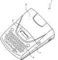
图1是处于盒盖6关闭状态的带打印装置1的俯视立体图。FIG. 1 is a top perspective view of the
图2是处于盒盖6打开状态的带打印装置1的俯视立体图。FIG. 2 is a top perspective view of the
图3是用于说明带盒30及盒安装部8的立体图。FIG. 3 is a perspective view for explaining the
图4是盒安装部8的平面图。FIG. 4 is a plan view of the
图5是平板支架12位于待机位置时的、安装了带盒30的盒安装部8的平面图。FIG. 5 is a plan view of the
图6是平板支架12位于打印位置时的、安装了带盒30的盒安装部8的平面图。FIG. 6 is a plan view of the
图7是头部支架74的正面图。FIG. 7 is a front view of the
图8是平板支架12的背面图。FIG. 8 is a rear view of the
图9是图8的Ⅰ-Ⅰ线方向的截面图。Fig. 9 is a sectional view taken along line I-I in Fig. 8 .
图10是表示带打印装置1的电气构成的框图。FIG. 10 is a block diagram showing the electrical configuration of the
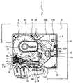
图11是带盒30的平面图。FIG. 11 is a plan view of the
图12是带盒30的底面图。FIG. 12 is a bottom view of the
图13是带盒30的部件展开图。FIG. 13 is an exploded view of parts of the
图14是壳体主体38的平面图。FIG. 14 is a plan view of the housing
图15是辊支撑孔64及带驱动辊46的分解立体图。FIG. 15 is an exploded perspective view of the
图16是带单元500的平面图。FIG. 16 is a plan view of the
图17是带单元500的部件展开的状态的纵向截面图。FIG. 17 is a longitudinal sectional view of a state in which components of the
图18是带单元500的组装状态的纵向截面图。FIG. 18 is a longitudinal sectional view of an assembled state of the
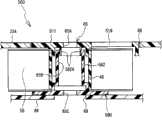
图19是带盒30中的臂部34的放大立体图。FIG. 19 is an enlarged perspective view of the
图20是以部分截面表示引导孔47的、带盒30的右侧面图。FIG. 20 is a right side view of the
图21是带盒30中的臂前面壁35的放大正面图。FIG. 21 is an enlarged front view of the
图22是从右侧观察到的安装带盒30前的盒安装部8的说明图。FIG. 22 is an explanatory diagram of the
图23是从右侧观察到的安装带盒30的中途的盒安装部8的说明图。FIG. 23 is an explanatory diagram of the
图24是从右侧观察到的安装带盒30后的盒安装部8的说明图。FIG. 24 is an explanatory diagram of the
图25是从正面观察到的由头部支架74支撑的带盒30的说明图。FIG. 25 is an explanatory diagram of the
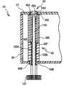
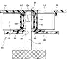
图26是从正面观察到的插入了带驱动轴100的带驱动辊46的纵向截面图。FIG. 26 is a longitudinal cross-sectional view of the
图27是从正面观察到的插入了辅助轴110的带单元500的纵向截面图。FIG. 27 is a longitudinal cross-sectional view of the
图28是表示平板支架12与图21所示的带盒30相对的状态的、图21的Ⅱ-Ⅱ线方向截面图。FIG. 28 is a sectional view taken along line II-II in FIG. 21 , showing a state where the
具体实施方式Detailed ways
以下参照附图说明将本发明公开化的实施方式。此外,参照的附图用于说明可采用本发明的技术特征,所记载的装置构造等不限于此,仅是说明例。Embodiments which disclose the present invention will be described below with reference to the drawings. In addition, the drawings referred to are for explaining the technical features that can be used in the present invention, and the described device structures and the like are not limited thereto and are merely illustrative examples.
参照图1~图28说明本实施方式涉及的带打印装置1及带盒30。在本实施方式的说明中,将图1的左下侧、右上侧、右下侧、左上侧分别作为带打印装置1的前侧、后侧、右侧、左侧。将图3的右下侧、左上侧、右上侧、左下侧分别作为带盒30的前侧、后侧、右侧、左侧。The
此外,图3所示的包括齿轮91、93、94、97、98、101的齿轮组,实际上被腔室8A的底面覆盖隐藏,但为了便于说明这些齿轮组,在图3中未图示腔室8A的底面。在图3中,图示形成盒安装部8的周围的壁部,但仅是示意图,图中所示的侧壁比实际的厚。在图5及图6中,对盒安装部8上安装了带盒30的状态,去除盒盖33及辅助盖体51来表示。In addition, the gear
首先说明本实施方式涉及的带打印装置1的概要构成。带打印装置1是可使用1台热敏型、接受型、层压型、热敏层压型等各种带盒的通用的带打印装置。热敏型是仅收纳热敏纸带的种类的带盒。接受型是收纳打印带和墨带的种类的带盒。层压型是收纳双面胶带、薄膜带及墨带的种类的带盒。热敏层压型是收纳双面胶带和热敏纸带的种类的带盒。First, the schematic configuration of the
如图1及图2所示,带打印装置1具有平面视图为长方形的主体盖2。主体盖2的前侧配置包括文字、标记及数字等字符键、各种功能键等的键盘3。键盘3的后侧设有可显示输入的文字、标记的显示器5。显示器5的后侧设有更换带盒30(参照图3)时开合的盒盖6。主体盖2的左侧面后方设有用于将打印完的带排出到外部的排出狭缝9。盒盖6的左侧面设有排出窗11,其在关闭盒盖6的状态下使排出狭缝9露出到外部。在盒盖6的前面大致中央部分,设有从下面向下方突出的钩状的卡止锁4。主体盖2中,在和卡止锁4对应的位置设置锁孔7。当盒盖6关闭时,卡止锁4嵌入到锁孔7,防止盒盖6自动打开。As shown in FIGS. 1 and 2 , the
参照图2~图6说明盒盖6下的主体盖2的内部构造。在图3~图6中,为便于理解,示意了主体盖2的内部构造(尤其是盒安装部8的开关、构造等)。如图2~图6所示,盒安装部8是可装卸带盒30的区域,包括腔室8A及角支撑部8B。腔室8A与盒壳体31的平面形状基本对应地凹陷设置,是具有平面状底面的凹部。角支撑部8B是从腔室8A的外边缘水平延伸的平面部。角支撑部8B是以下部位:在带盒30安装到盒安装部8时,与带盒30的周缘(具体是下述角部321~324)的下表面相对的部位。The internal structure of the
在盒安装部8的前部固定设置安装有具有散热体(未图示)的热敏头10的头部支架74。盒安装部8的外侧(图3中是右上侧)配置作为步进电机的带传送电机23。在带传送电机23的驱动轴的下端固定齿轮91。齿轮91经由开口与齿轮93啮合。齿轮93与齿轮94啮合。在齿轮94的顶面直立设置大致圆柱状的墨带缠绕轴95。齿轮94与齿轮97啮合。齿轮97与齿轮98啮合。齿轮98与齿轮101啮合。齿轮101的顶面直立设置大致圆柱状的带驱动轴100。带驱动轴100上,从基部向前端延伸的多个凸轮部件100A在平面视图中放射状地设置(参照图22)。A
在带盒30安装到盒安装部8的状态下,带传送电机23按逆时针方向旋转驱动齿轮91时,通过齿轮93、94,墨带缠绕轴95向逆时针方向旋转驱动。墨带缠绕轴95旋转驱动安装到墨带缠绕轴95的墨带缠绕卷轴(未图示)。进一步,齿轮94的旋转通过齿轮97、齿轮98、齿轮101传送到带驱动轴100,带驱动轴100按顺时针方向旋转驱动。带驱动轴100旋转驱动安装到带驱动轴100的带驱动辊46。齿轮98的后侧直立设置大致圆柱状的辅助轴110,稍后详述。With the
在角支撑部8B的两处设置两个定位销102、103。具体而言,在腔室8A的左侧设置定位销102,在腔室8A的右侧设置定位销103。定位销102及103在带盒30安装到盒安装部8时,插入到销孔52、53(参照图12),销孔52、53是在带盒30的底面形成的两个凹部,在带盒30的周缘部的左右位置,将带盒30定位到前后/左右方向。Two positioning
在盒安装部8的右侧后部直立设置大致圆柱状的引导轴120。引导轴120具有:直径不同的两个轴部(大径轴部120A及小径轴部120B);锥部120C(参照图22)。大径轴部120A是构成引导轴120的基部的轴部,是在引导轴120中直径最大的部位。小径轴部120B是构成引导轴120的前端的轴部,直径小于大径轴部120A。锥部120C是设置在大径轴部120A和小径轴部120B之间的、轴径从大径轴部120A到小径轴部120B逐渐减小的锥形的倾斜面。A substantially
参照图4说明直立设置在盒安装部8的各部件的位置关系。图4中的双点划线表示下述分割线J。带驱动轴100、引导轴120、辅助轴110、墨带缠绕轴95、头部支架74分别设置在和带盒30的辊支撑孔64、引导孔47、带支撑孔65、缠绕支撑孔67、头部插入部39对应的位置(参照图22)。The positional relationship of the components installed upright on the
带驱动轴100直立设置在盒安装部8中的包括位于前方的角部的第一轴设置区域8C中。第一轴设置区域8C与固定设置在盒安装部8的前部中央的头部支架74的左侧邻接,比打印带55的传送方向(以下称为带传送方向)中的热敏头10的打印位置相比位于下游侧。引导轴120直立设置在盒安装部8中的包括位于右后方的角部的第二轴设置区域8D中。即,盒安装部8的平面视图中,第二轴设置区域8D中包含的角部位于第一轴设置区域8C中包含的角部的对角。The
以平面视图中连接带驱动轴100和引导轴120的分割线J为基准,在平面视图中分割盒安装部8时,和分割线J相比位于后侧的是第一设置区域8E,和分割线J相比位于前侧的是第二设置区域8F。辅助轴110直立设置在第一设置区域8E,具体而言,从盒安装部8的平面视图中央观察位于左后侧。墨带缠绕轴95直立设置在第二设置区域8F,具体而言,从盒安装部8的平面视图中央观察位于右前侧。辅助轴110及墨带缠绕轴95在平面视图中以分割线J为中心,基本对称。Based on the dividing line J connecting the
在带驱动轴100的后侧邻接设置定位销102。在引导轴120的前侧邻接设置定位销103。定位销102、103使安装在盒安装部8的带盒30分别在带驱动轴100及引导轴120附近定位。A
直立设置在盒安装部8的各部件的高度关系因设置在前述腔室8A及角支撑部8B某一个上而不同。设置在角支撑部8B的部件(在本实施方式中是引导轴120、定位销102、103)和设置在腔室8A的部件(在本实施方式中是墨带缠绕轴95、带驱动轴100、辅助轴110、头部支架74)相比靠上直立设置。稍后论述直立设置在盒安装部8的各部件的高度关系。The height relationship of the components standing upright on the
返回到图2~图6,在头部支架74的前侧,臂状的平板支架12以轴支撑部12A为中心可摆动地被轴支撑。在平板支架12的前端,平板辊15及可动传送辊14同时可旋转地被轴支撑。平板辊15相对热敏头10可接触/分离。可动传送辊14相对嵌入了带驱动轴100的带驱动辊46可接触/分离。Returning to FIGS. 2 to 6 , on the front side of the
平板支架12上未图示的连接分离杆,其与盒盖6的开合联动,向左右方向移动。当盒盖6打开时,分离杆向右方移动,平板支架12向图5所示的待机位置移动。在图5所示的待机位置,因平板支架12离开盒安装部8,所以可将带盒30装卸到盒安装部8。平板支架12通过未图示的线圈弹簧总是弹性施力到待机位置。The unillustrated connection and separation lever on the
当盒盖6关闭时,分离杆向左方移动,平板支架12向图6所示的打印位置移动。在图6所示的打印位置上,平板支架12接近盒安装部8。因此,如向盒安装部8安装带盒30,则平板辊15通过打印介质的带(本实施方式中是打印带55)推压热敏头10。可动传送辊14通过带推压带驱动辊46。在图6所示的打印位置上,可使用带打印装置1安装到盒安装部8的带盒30进行打印。When the
带排出部49到排出狭缝9之间,设置传送打印完的带的传送路径。在该传送路径中,设有在规定位置切断打印完的带的切断机构17。切断机构17由以下构成:固定刃18;相对固定刃18,可在前后方向(图5及图6所示的上下方向)移动地被支撑的移动刃19。移动刃19通过切断电机24(参照图10)向前后方向移动。Between the
参照图4及7说明头部支架74的详细构成。头部支架74由一块板状部件形成,具有:底座部743、头部固定部744。底座部743固定到腔室8A的底面(未图示)的下方。头部固定部744如下配置:从底座部743开始大致垂直地弯曲,向上方延伸,且沿带打印装置1的左右方向配置。盒安装部8中的头部支架74的配置位置是,当安装了带盒30时,和下述头部插入部39对应的位置。但头部支架74的右端部和头部插入部39的右端部相比,向右侧延伸。热敏头10固定到头部固定部744的前面。The detailed structure of the
头部固定部744上设有从下方支撑安装到带打印装置1的带盒30的盒支撑部741。盒支撑部741是如下阶梯部:通过在正面视图中将头部固定部744的右端部L字型切口,形成在规定的高度位置。盒支撑部741相对热敏头10在带传送方向上游侧支撑带盒30。盒支撑部741设定在以下位置:距热敏头10的上下方向中心位置在上下方向上分离规定距离的位置。因此,盒支撑部741相对热敏头10的上下方向中心位置,成为在上下方向定位带盒30的基准。稍后详述盒支撑部741对带盒30的支撑。The
如图4~图6所示,在平板支架12的后侧面、即和热敏头10相对的一侧的面上,在比长度方向的中间位置略靠右侧,设置臂部检测部200。以下将平板支架12的后侧面称为盒相对面12B。臂部检测部200包括多个检测开关210。各检测开关210的开关端子222从盒相对面12B向盒安装部8大致水平地突出。As shown in FIGS. 4 to 6 , on the rear side of the
换言之,各检测开关210向与相对盒安装部8的带盒30的装卸方向(图3的上下方向)大致正交的方向突出,与盒安装部8内存在的带盒30的前面(具体而言是下述前端侧前壁525)相对。各检测开关210在带盒30安装在盒安装部8的适当位置的状态下,设置在和下述臂部标志部800(参照图3)相对的高度位置。In other words, each
参照图8及图9说明平板支架12具有的检测开关210的详细配置及构造。如图8所示,在平板支架12的盒相对面12B上,五个贯通孔12C在上下方向并列三列设置。具体而言,是最上列两个、正中间的一列两个、最下面一列1个的配置。贯通孔12C的左右方向位置分别不同。具体而言,从盒相对面12B的右侧(图8的左侧)开始依次按照最下列、最上列的右侧、中间列的右侧、最上列的左侧、中间列的左侧的顺序,五个贯通孔12C锯齿状配置。对应这些贯通孔12C,设置五个检测开关210。The detailed arrangement and structure of the
如图9所示,检测开关210具有:大致圆筒状的主体部221,设置在平板支架12的内部;棒状的开关端子222,从主体部221的一端开始可向轴线方向进退。主体部221的另一端安装到开关支撑板220上,设置在平板支架12的内部。在主体部221的一端,通过形成在平板支架12的盒相对面12B上的多个贯通孔12C,开关端子222可进退。开关端子222总是通过设置在主体部221内部的弹簧部件(未图示),保持从主体部221伸出的状态。开关端子222未被推压时,是从主体部221伸出的状态(断开状态),被推压时是退入到主体部221内的状态(接通状态)。As shown in FIG. 9 , the
在带盒30安装到盒安装部8的情况下,当平板支架12向待机位置移动时(参照图5),各检测开关210离开带盒30,因此全部变为断开状态。平板支架12向打印位置移动时(参照图6),各检测开关210与带盒30的前面(具体而言是前端侧前壁525)相对,通过臂部标志部800选择性地被推压。带打印装置1根据各检测开关210的接通/断开的组合,检测带盒30的带种类。稍后详述臂部检测部200对带种类的检测。When the
如图4及图5所示,在平板支架12的盒相对面12B上,设置作为向左右方向延伸的板状的突起部的卡止片225。卡止片225和检测开关210的开关端子222一样,从盒相对面12B向盒安装部8大致水平地突出。即,与盒安装部8内存在的带盒30的前面(具体而言是下述前端侧前壁525)相对地突出。卡止片225在带盒30安装到盒安装部8的适当位置的状态下,设置在与下述卡止孔820(参照图3)相对的高度位置。As shown in FIGS. 4 and 5 , on the case-facing
参照图8及图9,说明平板支架12中的卡止片225的配置及构成。如图8所示,卡止片225在平板支架12的盒相对面12B中,和最上列的检测开关210相比设置在上方,从最上列的右侧(图8的左侧)的检测开关210和最下列的检测开关210之间的左右方向位置向右侧延伸。如图9所示,卡止片225从平板支架12的盒相对面12B向后方(图9中是左侧)突出地与平板支架12一体成型。以盒相对面12B为基准,卡止片225的突出高度与各检测开关210的开关端子222的突出高度相比基本相同,或略大。Referring to FIG. 8 and FIG. 9 , the arrangement and structure of the
参照图10说明带打印装置1的电气构成。如图10所示,带打印装置1具有形成在控制基板上的控制电路部400。在控制电路部400中,ROM402、CGROM403、RAM404、输入输出接口411经由数据总线410连接到控制各设备的CPU401。The electrical configuration of the
ROM402中存储CPU401为控制带打印装置1而执行的各种程序。用于确定安装在盒安装部8的带盒30的带种类的表格也存储在ROM402中。CGROM403中存储用于打印字符的打印用光点图形数据。RAM404中设有文本存储器、打印缓冲存储器等多个存储区域。Various programs executed by the
输入输出接口411中连接检测开关210、键盘3、液晶显示器(LCD)405、驱动电路406、407、408等。驱动电路406是用于驱动热敏头10的电子电路。驱动电路407是用于驱动带传送电机23的电子电路。驱动电路408是用于驱动使移动刃19传送的切断电机24的电子电路。液晶驱动电路(LCDC)405具有用于将显示数据输出到显示器5的视频RAM(未图示)。The
接着说明本实施方式涉及的带盒30的构造。本实施方式的带盒30是可更换盒壳体31内收纳的带单元500的回填式带盒。Next, the structure of the
参照图3、图5、图6、图11~图13说明带盒30的整体构造。在图13中,为了明示壳体主体38的前部形状,卸下带驱动辊46及辅助盖体51进行图示。带盒30具有盒壳体31,它是整体上具有在平面视图中带圆的角部的大致长方体状(箱型)的筐体。盒壳体31由以下部分构成:壳体主体38、盒盖33、辅助盖体51。壳体主体38是向上方开口的箱状体,收纳有带单元500。盒盖33是可相对壳体主体38的开口从上方自由装卸的盖。辅助盖体51是覆盖设置在壳体主体38的带驱动辊46等的上方的板状部件。The overall structure of the
上述盒壳体31包括:一对上壁面85及下壁面86,在上下方向相向配置,是矩形的平面;侧壁87,在上壁面85及下壁面86的外边缘以规定高度形成。在本实施方式中,上壁面85包括:下述盒盖33的上板部33A(参照图13)、辅助盖体51。下壁面86是下述壳体主体38的下板。The
盒壳体31中,上壁面85及下壁面86的周缘部整体无需被侧壁87包围。例如也可在侧壁87的一部分(例如后壁)上设置使盒壳体31内露出的开口部,或在面向该开口部的位置上设置连接上壁面85及下壁面86的凸起部。In the
从带盒30的平面视图中央观察时,在其左后侧形成带支撑孔65,其可旋转地支撑带单元500具有的打印带55。在带盒30装卸时,辅助轴110插入或脱离于带支撑孔65,对此稍后详述。A
从带盒30的平面视图中央观察时,在其右前侧形成缠绕支撑孔67。缠绕支撑孔67可旋转地支撑墨带缠绕卷轴(未图示),该墨带缠绕卷轴从墨带卷轴(未图示)拉出墨带,缠绕在文字等的打印中使用的墨带。本实施方式的打印带55是不使用墨带即可进行文字等的打印的热敏发色性的热敏带。因此,带盒无需收纳墨带,从而不具有墨带卷轴及墨带缠绕卷轴。A winding
在带盒30的前面右侧设有臂部34,其向带盒30的前方略微延伸,且向中央直角返回。臂部34引导盒壳体31内收纳的打印带55,从设置在前端的排出口34A排出到头部插入部39的前方。头部插入部39是由臂部34包围的间隙,插入上述头部支架74。On the front right side of the
在带盒30的左前部设有辊支撑孔64。在辊支撑孔64的内侧,插入/脱离上述带驱动轴100的带驱动辊46可旋转地被支撑。带驱动辊46通过与相对的可动传送辊14的联动,拉出未使用的打印带55。从带驱动辊46观察,在带传送方向的上游,设有上下一对限制部件63。限制部件63在从热敏头10观察的带传送方向下游,在宽度方向限制打印完的带,向带排出部49引导。A
带排出部49从盒壳体31的左侧面的前端部开始略向前方分离地设置,是跨越上壁面85和下壁面86的板状部件。带排出部49将经带驱动辊46传送来的打印完的打印带55,引导到与盒壳体31的左侧面的前端部之间形成的路径内,从位于路径终端的排出狭缝9排出。The
在带盒30的右后部设有引导孔47,其在带盒30装卸时,插入/脱离上述引导轴120。本实施方式的引导孔47,在平面视图中,前后方向上相对的两边呈直线状,且左右方向相对的两边具有距引导孔47的开口中心的距离恒定的曲线状的开口形状。引导孔47的开口宽度在平面视图中,在通过引导孔47的开口中心的全部方向上,大于引导轴120的小径轴部120B的直径。但引导孔47在平面视图中,通过引导孔47的开口中心的左右方向的开口宽度最大,在平视图像中通过引导孔47的开口中心的前后方向的开口宽度最小。通过引导孔47的开口中心的前后方向的开口宽度与引导轴120的大径轴部120A的直径基本相等。A
在带盒30的前面(具体是臂部34的前面)设有臂部标志部800及卡止孔820。臂部标志部800是人员可确定收纳在带盒30中的带种类的部位。并且,臂部标志部800是以下部位:通过选择性地推压臂部检测部200的检测形状210,使带打印装置1检测出带盒30的带种类。卡止孔820中插入卡止片225。稍后另述臂部标志部800及卡止孔820。An
参照图3、图11~图15说明壳体主体38。在图14中,为了明示壳体主体38的前部形状,卸下辅助盖体51进行图示。实际上,从壳体主体38中的前部中央到左端部设置辅助盖体51。因此,壳体主体38在带单元500及盒盖33未组装的状态下,除了设置辅助盖体51的部位外,向上方开口。The casing
如图11、图12及图14所示,壳体主体38无论带盒30的带种类如何,具有形成为相同宽度(上下方向的长度相同)的四个角部321~324。以下称左后方的角部为第一角部321、右后方的角部为第二角部322、右前方的角部为第三角部323、左前方的角部为第四角部324。四个角部321~324在平面视图中以直角从壳体主体38的侧面向外侧方向突出。但左前方的第四角部324因带排出部49设置在角部,因此不是直角。As shown in FIGS. 11 , 12 and 14 , the case
如图12所示,各角部321~324的下面在带盒30安装到盒安装部8时,是和上述角支撑部8B相对的部位。在第二角部322及第四角部324的下面两处,分别设置和上述定位销102、103对应的销孔52、53。As shown in FIG. 12 , the lower surfaces of the
如图3所示,对在壳体主体38的上下(高度)方向上,在和各角部321~324相同的位置且相同的宽度整周缠绕壳体主体38的侧面的部位(包括各角部321~324),称为共用部32。具体而言,共用部32是,相对壳体主体38的上下(高度)方向的中心线N,在上下方向具有对称宽度的部位(参照图21)。带盒30的高度对应收纳的打印介质(在本实施方式中是打印带55)的带宽度而不同。但共用部32的宽度(上下方向的长度)T无论这些带的带宽度,设定为相同尺寸。As shown in FIG. 3 , in the up-down (height) direction of the
例如,当共用部32的宽T为12mm时,当带宽度变大时(例如18mm、24mm、36mm),壳体主体38的高度也相应变大,但共用部32的宽T(参照图21)是恒定的。带宽度小于共用部32的宽T时(例如6mm、12mm),壳体主体38的高度(宽)是共用部32的宽T+规定宽度。此时,壳体主体38(即盒壳体31)的高度最小。For example, when the width T of the
如图11~图14所示,在壳体主体38的前面,作为平面视图中大致半圆形的槽部的半圆槽42,在壳体主体38的上下方向(即从上壁面85到下壁面86)设置。半圆槽42是如下设置的退避部:当带盒30安装到盒安装部8时,平板支架12的轴支撑部12A(参照图4)不与带盒30干扰。As shown in FIGS. 11 to 14, on the front of the
将在壳体主体38中从半圆槽42向左延伸的部分,称为构成带盒30的前面的一部分的臂部前面壁35。由臂部前面壁35及臂部背面壁36规定的、从壳体主体38的右侧向左侧延伸的部位,是上述臂部34,上述臂部背面壁36在从臂部前面壁35向后方分离的位置上在高度方向上设置。臂部前面壁35的左端部向后方弯曲,臂部前面壁35及臂部背面壁36的左端之间形成的向上下方向延伸的间隙,是上述排出口34A。在臂部34中,引导从带单元500拉出的打印带55,从排出口34A排出到露出部77。露出部77是形成在排出口34A和带排出部49之间的、打印带55的露出部位。A portion extending leftward from the
臂部前面壁35上设有识别用开口部35A,它是具有从臂部前面壁35的上边向下方切口的形状的凹部。识别用开口部35A从排出口34A的略靠右侧到半圆槽42的略靠左侧,从壳体主体38的下板(即下壁面86)向上形成。在识别用开口部35A上形成从下壁面86的前端部向后切口的切口部35B。壳体主体38中收纳了带单元500时,下述前端侧前壁525嵌入到识别用开口部35A中,对此稍后详述。The
由臂部背面壁36、及设置在臂部背面壁36后方的圆周壁面包围的、在上下方向贯通带盒30的平面视图大致长方形的空间,是上述头部插入部39。头部插入部39通过露出部77在带盒30的前面与外部连接,露出部77是设置在带盒30前面的开口。在露出部77中,从臂部34的排出口34A排出的打印带55的一面向前方露出,且另一面与后方的热敏头10相对。热敏头10可对通过露出部77露出的打印带55进行打印。The substantially rectangular space in plan view that penetrates the
头部插入部39的右端部上形成退避部50,其在平面视图中从头部插入部39向右方凹陷,在上下方向贯通。退避部50是如下部位:当头部插入部39中插入头部支架74时,为使头部支架74的右端部(具体是盒支撑部741)不与壳体主体部38接触,而向上方退避。The right end portion of the
头部插入部39的背后设有固定了下述弹性卡止钩体33C的卡止长孔139。在壳体主体38的后壁38A的两侧位置上,贯穿设置分别与下述卡止爪33B卡止的一对卡止孔134。进一步,在头部插入部39和壳体主体38的左侧壁之间,形成可旋转自如地支撑上述带驱动辊46的辊支撑孔64。On the back of the
如图15所示,辊支撑孔64包括在上下方向相对设置的两个开口部64A、64B。开口部64A形成在辅助盖体51(即上壁面85)上。开口部64B形成在壳体主体38的底壁(即下壁面86)上。在开口部64A、64B的各附近位置上,沿盒壳体31的前端边缘,上述限制部件63分别朝相对的方向突出地设置。一对限制部件63的基端的间隔大小和打印带55的带宽度相同地设定。As shown in FIG. 15 , the
带驱动辊46是具有与盒壳体31的宽度(即上下方向的长度)基本相等的高度的圆筒体。带驱动辊46的主体部46E的直径大于开口部64A、64B,其外周面是和打印介质抵接的辊面46C。辊面46C的上下方向长度(即带传送宽度)与打印介质的带宽度相同地设定。从带驱动辊46的主体部46E在上下方向分别突出的上端部46A及下端部46B,直径分别比开口部64A、64B略小。在带驱动辊46的内部,通过在上下方向贯通主体部46E的轴孔46D,两端部46A、46B连通。The
在盒壳体31的内部,上端部46A与开口部64A嵌合,且下端部46B与开口部64B嵌合。主体部46E从下方与辅助盖体51抵接,限制向上方的移动,从上方与壳体主体38抵接,限制向下方的移动。这样一来,带驱动辊46由两端部46A、46B支撑的同时,在盒壳体31内以轴线为中心自由旋转。Inside the
在带驱动辊46的内周面(即形成轴孔46D的内壁)上,在其下端设置多个扣合肋46F(参照图26)。当带盒30安装到盒安装部8时,上述带驱动辊100通过开口部64B插入到轴孔46D。在设置在带驱动辊46的多个扣合肋46F上,啮合形成在带驱动轴100周围的多个凸轮部件100A。这样一来,带驱动轴100的旋转传送到带驱动辊46(即伴随带驱动轴100的旋转,带驱动辊46旋转)。On the inner peripheral surface of the belt drive roller 46 (that is, the inner wall forming the
如图14所示,在壳体主体38的左后部设有带收纳部141,其收纳下述带单元500具有的带卷轴40。带收纳部141在壳体主体38上安装了盒盖33的状态下,具有可旋转地收纳下述带卷轴40的深度。带收纳部141的深度对应带单元500具有的带宽度而不同。As shown in FIG. 14 , a
在壳体主体38的右部设有支架收纳部142,其收纳下述带单元500具有的带支架510。支架收纳部142具有和带收纳部141及臂部34相同程度的深度。支架收纳部142是以下空间:与带收纳部141在左右方向连通,且与臂部34在左右方向连通。即,带收纳部141、支架收纳部142、臂部34是在平面方向上连通并向上方开口的一个空间,形成收纳了带单元500的单元收纳部140。On the right side of the case
贯通壳体主体38的底壁(即下壁面86),分别形成带用开口部69、开口部67B、第三引导形成孔47C。带用开口部69设置在带收纳部141的大致中心位置上,是和上述带支撑孔65相对的孔部。开口部67B设置在臂部34的后方,是构成上述缠绕支撑孔67的一部分的孔部。第三引导形成孔47C设置在壳体主体38的右后部,是构成上述引导孔47的一部分的孔部。稍后详述带用开口部69、开口部67B、第三引导形成孔47C。The
在壳体主体38的底壁(下壁面86)上,夹持缠绕到带卷轴40的打印带55的传送路径,设置一对角孔144、145。当带盒30安装到盒安装部8时,由直立设置在盒安装部8内的发光器和受光器构成的光敏传感器(未图示),嵌入到一对角孔144、145中。在执行带打印时,从带卷轴40拉出的打印带55通过光敏传感器(未图示)检测。A pair of corner holes 144 , 145 are provided on the bottom wall (lower wall surface 86 ) of the housing
参照图13、图16~图18说明带单元500。如图13及图16所示,带单元500具有:缠绕有打印带的带卷轴40;旋转自如地支撑带卷轴40的带支架510。The
带卷轴40是形成了在上下方向贯通其内部的轴孔40A的圆筒体,具有和打印带55的带宽度基本相同的高度尺寸。打印带55是如下热敏纸带:在基底带的一面上形成热敏发色层,在另一面通过粘合剂层粘贴剥离纸。打印带55以热敏发色层为内层,缠绕到带卷轴40的外周面。The
带支架510是在平面视图中具有与壳体主体38的单元收纳部140基本对应的形状的合成树脂制的板状部件。带支架510具有:旋转支撑部511、连接设置部512、引导部513、下卷轴580。旋转支撑部511在平面视图中从带卷轴40的轴孔40A向径向外侧(图16中是右方)延伸,与缠绕到带卷轴40的打印带55的上侧面相对支撑。在旋转支撑部511的左端边缘部,形成面向打印带55的缠绕中心(即轴孔40A)的开口部65A。在旋转支撑部511上形成观察窗口519,其向打印带55的旋转部中的径向(在此是从开口部65A观察时的右方)延伸。The
如图17及图18所示,在旋转支撑部511的下表面一侧,嵌入到带卷轴40的轴孔40A的凸座部514向下突出地设置。在凸座部514的外周形成多个卡止孔515。在从下卷轴580中的凸缘部581向上突出的筒部582的内壁面,多个卡止爪582向内突起设置。筒部582插入到轴孔40A内,各卡止爪582A分别固定到对应的卡止孔515时,旋转支撑部511和下卷轴580连接。在旋转支撑部511及下卷轴580的间隙处,带卷轴40以筒部582为中心旋转自如地被保持。As shown in FIGS. 17 and 18 , on the lower surface side of the
下卷轴580具有:在上下方向贯通的轴孔65B;与轴孔65B连通并向下方开口的开口部65C。如上所述,在夹持缠绕有打印带55的带卷轴40、并连接旋转支撑部51及下卷轴580的状态下(即组装了带单元500的状态),形成带支撑孔65,它是开口部65A、轴孔65B、开口部65C在上下方向连通的贯通孔。The
如图13及图16所示,连接设置部512在旋转支撑部511的右端部中通过阶梯连接,从旋转支撑部511的右端部延伸到径向外侧(在图16中是右侧)。在连接设置部512中的左右方向的大致中央部,形成截面大致U字状的引导槽512A,该引导槽512A将从带卷轴40拉出的打印带55向右前方向引导。在连接设置部512的右端边缘部,构成上述引导孔47的一部分的第二引导形成孔47B在上下方向贯通形成,稍后详述。As shown in FIG. 13 and FIG. 16 , the
引导部513沿着由带卷轴40支撑的打印带55的缠绕方向(图16中是左下方向),从连接设置部512延伸。在引导部513的内部,经由引导槽512A的打印带55,引导到带支架510中的设置在带传送方向最下游侧的排出口500A。引导部513包括:下侧引导壁521、前侧引导壁522、后侧引导壁523、内侧引导壁524。The
下侧引导壁521是在引导部513内传送的打印带55的下端相对的壁部,以和引导槽512A的底面相同的高度连接。下侧引导壁521沿带传送方向从连接设置部512向左前方向(图16中是左下方向)延伸。在下侧引导壁521上,在带单元500收纳在壳体主体38的内部的状态下,形成和上述角孔144重叠的角孔521A。内侧引导壁524是沿角孔521A以和打印带55的带宽度对应的高度直立设置的壁部。The
前侧引导壁522及后侧引导壁523是,沿下侧引导壁521的两个边缘部以和打印带55的带宽度对应的高度直立设置的壁部。换言之,前侧引导壁522及后侧引导壁523与从带卷轴40拉出的打印带55的面平行、且沿引导部513中的打印带55的传送路径设置。具体而言,前侧引导壁522从带支撑孔65(参照图18)观察,和在下侧引导壁521上引导的打印带55相比,设置在径向外侧。后侧引导壁523从带支撑孔65(参照图18)观察,和在下侧引导壁521上引导的打印带55相比,设置在径内侧。此外,后侧引导壁523的基部侧(图16中是上侧)是以下弯曲部523A:在带单元500收纳到壳体主体38的内部的状态下,在平面视图中沿开口部67B的轮廓弯曲。The
前侧引导壁522的前端侧是,与连接设置部512延伸的方向(在图16中是左右方向)平行延伸的前端侧前壁525。后侧引导壁523的前端侧是在前端侧前壁525的后侧(图16中是上侧),与前端侧前壁525平行延伸的前端侧后壁526。下侧引导壁521的前端侧是由前端侧前壁525和前端侧后壁526夹持的前端侧下壁527。即,前端侧前壁525、前端侧后壁526、前端侧下壁527设置在引导部513中的带传送方向下游侧。前端侧前壁525和前端侧后壁526的间隔(前端侧下壁527的前后方向长度)小于臂部34的前后方向长度。前端侧前壁525及前端侧后壁526的各左端之间形成的在上下方向延伸的间隙,是上述排出口500A。The front end side of the front
前端侧前壁525具有和上述识别用开口部35A基本一致的宽(左右方向长度)和高度(上下方向长度)。带单元500收纳到壳体主体38内部时,前端侧前壁525嵌入到识别用开口部35A,与臂部前面壁35同时构成盒壳体31的前面的一部分。在前端侧前壁525上设置臂部标志部800及卡止孔820,稍后详述。The front end side
从带卷轴40拉出的打印带55,从上述引导槽512A向右前方(图16中是右下方向)传送,引导到前侧引导壁522和内侧引导壁524之间。打印带55沿内侧引导壁524的右壁移动后,向左前方向传送,引导到前端侧前壁525和前端侧后壁526之间。打印带55沿前端侧后壁526的右端壁移动后,向左方传送,从排出口500A排出。在引导部513的前端侧设有限制打印带55向宽度方向移动的下限制部528及上限制部530。The
下限制部528是如下突出条:在前端侧下壁527的左右方向的大致中央位置向上方略微突出,跨越前端侧前壁525和前端侧后壁526向前后方向延伸。上限制部530是如下突出片:设置在前端侧后壁526的左端部上端,从前端侧后壁526向前方突出。下限制部528及上限制部530分别限制在前端侧前壁525和前端侧后壁526之间引导的打印带55向下方及上方的移动。下限制部528和上限制部530的上下方向的距离和打印带55的宽度相同。The lower restricting
下侧引导壁521上设有支撑支承部550,用于带盒30安装到带打印装置1时的上下方向的定位。具体而言,支撑支承部550在带单元500收纳在壳体主体38的内部的状态下,形成在与上述退避部50(参照图14)重叠的位置上。支撑支承部550是使下侧引导部521向上凹陷的凹部,且从后侧引导壁523向右方凹陷。A
支撑支承部550具有支撑面550A,它是和下侧引导壁521相比位于上方的平面部(凹部的底部)。带支架510的上下方向(高度方向)中的支撑面550A的位置、及收纳在盒壳体31的打印带55的宽度方向中心位置,无论带盒30的带种类如何,即即使带支架510的上下方向的高度不同,也是恒定的。因此,收纳在带盒30的打印带55的宽越大,从下侧引导壁521看到的支撑支承部550的深度越大。此外,支撑面550A位于距打印带55的宽度方向中心位置在上下方向上离开相同距离的位置上。即,支撑面550A在带支架510中位于相同高度位置。在本实施方式中,打印带550的宽度方向中心位置、带支架510的上下方向中心位置一致。The
支撑面550A在带盒安装到盒安装部8时,也作为通过设置在头部支架74的盒支撑部741从下方支撑的部位作用。并且,支撑面550A是带支架510中的基准面。基准面是指,进行某个部位的尺寸设定、尺寸测定时,作为基准使用的面。在本实施方式中,支撑面550A作为对限制部(下限制部528及上限制部530)的基准面设置,限制部限制打印带55向宽度方向的移动。The
换言之,下限制部528及上限制部530以支撑面550A为基准面,设定带支架510的上下方向的高度位置。具体而言,下限制部528的突出端(上端)和支撑面550A的上下方向的距离、及上限制部530的下端和支撑面550A的上下方向的距离,对应带宽度设定。这些限制部位于和作为基准面的支撑面550A接近的位置。In other words, the lower restricting
进行限制部的尺寸设定、制造后的尺寸测定时一直使用的基准位置(例如销孔52、53的底部),位于离开限制部的位置,因此成型两者的模具的模型会不同。这种情况下,基准位置的模型越远,制造的带支架510的限制部的尺寸误差越大。即使可用相同模型形成,当位于基准位置和限制部分离的位置时,也存在测定误差,尺寸精度变低。如本实施方式所述,如使限制部和基准面的距离较近,则测定误差变少,以相同模型形成两者的可能性变大。The reference position (for example, the bottom of the pin holes 52 and 53 ) which is always used for setting the size of the restricting part and measuring the size after manufacture is located away from the restricting part, so the models of the two molds are different. In this case, the farther the model at the reference position is, the larger the dimensional error of the manufactured regulation portion of the
并且,在制造带单元500后,以支撑面550A为基准,易于进行各限制部的尺寸管理。例如,检测带单元500时,将作为基准面的支撑面550A放置到夹具的放置面上,进行各限制部的尺寸测定。此时,各限制部和基准面的距离比现有技术中近,因此检查人员可正确地测定尺寸。In addition, after the
并且,支撑面550A在上下方向上与由带卷轴40保持的带的宽度方向中心位置相隔一定距离地设置。因此,相对支撑面550A的上下方向位置的带的上下方向位置变得明确,带的传送精度进一步提高。进一步,在本实施方式中,带的宽度方向中心位置和支撑面550A的距离不取决于带的宽度,是恒定的。因此,对于收纳了具有不同带宽度的带的多种带单元500,可将支撑面550A的位置设定为统一的基准,易于进行带支架510的尺寸测定、部件管理。Further, the supporting
参照图11~图13说明盒盖33。盒盖33是盒主体38中,具有与和头部插入部39相比占据后方的部位基本相同的形状及大小的、矩形的板状部件。在盒盖33的后边缘的左右两侧位置上,一对卡止爪33B向下突起设置。在盒盖33的前边缘的左右方向的大致中央位置,设置从上板部33A向下延伸设置的、在侧面视图中大致U字状的弹性卡止钩体33C。在弹性卡止钩体33C的前端侧形成向上方弯曲的把持部。The case cover 33 will be described with reference to FIGS. 11 to 13 . The case cover 33 is a rectangular plate-shaped member having substantially the same shape and size as a portion occupying the rear of the
盒盖33上,在上下方向贯通上板部33A,形成支撑开口68、开口部67A、第一引导形成孔47A等。支撑开口68设置在和上述带收纳部141相对的位置上,是具有和上述旋转支撑部511对应的形状的开口部。开口部67A设置在盒盖33的前部,是构成上述缠绕支撑孔67的一部分的孔部。第一引导形成孔47A设置在盒盖33的右后部,是构成上述引导孔47的一部分的孔部。支撑开口68、开口部67A、第一引导形成孔47A的详情稍后论述。In the
如图13所示,带盒30组装时,带单元500从上方收纳到壳体主体38的单元收纳部140中。这样一来,如图5及图6所示,带收纳部141中收纳带卷轴40,且在支架收纳部142中收纳带支架510。壳体主体38的角孔144与带支架510的角孔521A在上下方向连通。壳体主体38的开口部67B不被带支架510的弯曲部523A覆盖,而露出到上方。As shown in FIG. 13 , when the
进一步如图19所示,引导部513(参照图13)的前端侧(前端侧前壁525、前端侧后壁526、前端侧下壁527)收纳在臂部34的内部,且前端侧前壁525从上方嵌入到壳体主体38的识别用开口部35A。这样一来,设置在前端侧前壁525的臂部标志部800及卡止孔820从壳体主体38(具体是臂部34)的内部向前方露出。As further shown in FIG. 19, the front end side (the front end side
如图12所示,在带单元500收纳到壳体主体38的状态下,带单元500的带支撑孔65(参照图18)通过带用开口部69,露出到带盒30的下方。带支架510的支撑面550A通过壳体主体38的退避部50向下方露出。此外,当带盒30安装到壳体安装部8时,支撑面550A位于头部插入部39的外周上,面向头部插入部39。具体而言,支撑面550A以热敏头10(参照图5及图6)的插入位置(具体是打印位置)为基准,位于带传送方向的上游。As shown in FIG. 12 , when the
带盒30在收纳了带单元500的壳体主体38上安装盒盖33并组装。这样一来,如图3及图13所示,盒盖33的开口部67A和壳体主体38的开口部67B相对,形成在上下方向贯通盒壳体31的缠绕支撑孔67。带单元500的旋转支撑部511嵌入到盒盖33的支撑开口68。通过支撑开口68,观察窗口519可从带盒30的上方目视地露出。如图20所示,盒盖33的第一引导形成孔47A、带单元500的第二引导形成孔47B、壳体主体38的第三引导形成孔47C连通,形成在上下方向贯通盒壳体31的引导孔47。The
参照图19及图21详细说明臂部标志部800及卡止孔820。臂部标志部800在和上述检测开关210分别对应的位置上,包括非推压部801及推压部802的任意一个。非推压部801除了沿前端侧前壁525的下端边缘形成的情况外,是可插入/脱离开关端子222的正面视图纵向长的长方形的开关孔。推压部802是不可插入/脱离开关端子222的面部。本实施方式的臂部标志部800在和五个检测开关210对应的五个位置上,具有非推压部801及推压部802的任意一个。The
非推压部801和推压部802以和带盒30的带种类对应的特定的模式配置。卡止孔820是设置在前端侧前壁525的右上方的、平面视图为横向长的长方形的贯通孔。以下统称非推压部801及推压部802时、或不指定某一个时,仅称为标志部。The
臂部标志部800作为标志部包括至少一个孔部(在本实施方式中是非推压部801),只要表示带种类即可。在本实施方式中,在带单元500的部且侧引导壁522(具体是前端侧前壁525)上设置臂部标志部800。因此,通过在引导打印带55的壁部(在本实施方式中是前端侧前壁525)上设置臂部标志部800,带单元500无需用于设置臂部标志部800的专用部件。The
臂部标志部800的标志部(非推压部801及推压部802)的至少一部分在前端侧前壁525中设置在规定的高度T1的范围内。优选标志部(非推压部801及推压部802)的至少一部分设置在:前端侧前壁525中的、以盒壳体31的上下(高度)方向上的中心线N为中心的上下方向对称的共用标志部831内。At least a part of the indicator portion (the
规定的高度T1是具有多个不同高度的带盒30中,具有最小高度的带盒30的高度尺寸。将位于前端侧前壁525中的规定高度T1范围内的区域,称为共用标志部831。此外,在盒壳体31的高度尺寸大于规定高度T1的宽幅盒中,可在共用标志部831的上方及下方的至少任意一个上进一步设置标志部。The predetermined height T1 is the height dimension of the
本实施方式的臂部标志部800包括设置在共用标志部831内的五个标志部800A~800E。五个标志部800A~800E在共用标志部831的高度T1的范围内三列设置,且各标志部的左右方向的位置分别不同。即,五个标志部800A~800E在上下方向不重叠地锯齿状配置。因此,连接各标志部800A~800E的线与带盒30的装卸方向(即上下方向)交叉。The
具体而言,共用标志部831中,从左面倒右侧,按照非推压部801、推压部802、推压部802、推压部802、非推压部801的顺序,五个标志部800A~800E基本等间隔地排列。这五个标志部800A~800E在共用标志部831中的三列排列。从左侧开始第两个和第四个标志部800B、800D构成上列,从左侧开始第一个和第三个标志部800A、800C构成中列,从左侧开始第五个标志部800E构成下列。本实施方式的标志部800E是沿前端侧前壁525的下端边缘形成的非推压部801。因此,和标志部800E对应的非推压部801和其他非推压部801(标志部800A)相比,上下方向长度较小,是在正面视图中大致呈正方形的切口部。Specifically, in the common marking part 831, from the left to the right side, there are five marking parts in the order of the
卡止孔820是设置在上述卡止片225对应的位置的、平面视图中在左右方向长的长方形的贯通孔。本实施方式的卡止孔820和臂部标志部800的所有标志部相比设置在上方,且从与位于最右侧的标志部(图21的例子中是最下列的非推压部801)基本相同的左右方向位置开始向右方延伸。The
臂部标志部800的标志部(非推压部801及推压部802)的配置模式基于和带种类对应的预定规则。具体而言,标志部800A、800B、800E分别通过非推压部801及推压部802的组合,表示收纳在带盒30的带的宽(例如3.5mm~36mm七种)。标志部800C表示通过非推压部801及推压部802的任意一个表示收纳在带盒30的带的打印方式(例如正像打印或镜像打印)。标志部800D表示通过非推压部801及推压部802的任意一个表示收纳在带盒30的带的颜色信息(例如打印颜色是黑色或黑色以外的颜色)。因此,根据和带种类对应的预定的规则性配置臂部标志部800的标志部,从而可使人目视臂部标志部800来识别带种类。The arrangement pattern of the marking portions (the
在本实施方式的带单元500中,从带卷轴40的轴孔40A观察时位于径向外侧的前端侧前壁525上,设有臂部标志部800。因此,例如在制造带单元500时,在将带卷轴40组装到带支架510前,通过确认臂部标志部800所示的带种类,作业人员可识别应组装到带支架510的带的种类。进一步,前端侧前壁525与排出口500A邻接,因此作业人员可同时目视从排出口500A拉出的带及臂部标志部800。因此,在带卷轴40组装到带支架510后,作业人员可参照从排出口500A拉出的带的种类是否与臂部标志部800所示的带种类一致。In the
在本实施方式的带盒30中,带单元500收纳到壳体主体38时,前端侧前壁525嵌入到识别用开口部35A。因此,例如在制造带盒30时,在带单元500收纳到壳体主体38前,通过识别臂部标志部800所示的带种类,作业人员可识别组装到带支架510的带的种类。进一步,因识别用开口部35A与排出口34A邻接,所以用户可同时目视从排出口34A拉出的带及臂部标志部800。因此,在带单元500收纳到壳体主体38后,作业人员可参照从排出口34A拉出的带的种类是否与臂部标志部800所示的带种类一致。In the
用户更换壳体主体38中收纳的带单元500时也一样。即,在更换壳体主体38中收纳的带单元500前,用户可参照臂部标志部800识别新的组装到带支架510的带种类。在带单元500收纳到壳体主体38后,用户可参照从排出口34A拉出的带的种类是否与臂部标志部800所示的带种类一致。如上所述,通过在带单元500上设置臂部标志部800,可抑制错误种类的带收纳到盒壳体31内。The same applies when the user replaces the
而当臂部标志部800的上下方向长度小于规定幅度时,多个标志部800A~800E中设置在最下方的标志部800E,和其他标志部800A~800D相比,上下方向长度会变小。这样一来会出现以下可能:虽然标志部800E是非推压部801,但和标志部800E相对的检测开关210的开关端子222与壳体主体38的下板(即下壁面86)接触,错误变为接通状态。On the other hand, when the vertical length of the
在本实施方式中,当标志部800E是非推压部801时,当前端侧前壁525安装到识别用开口部35A时,该非推压部801与形成在识别用开口部35A的切口部35B在上下方向连通(参照图19及图21)。这样一来,在标志部800E的上下方向长度小于其他标志部800A~800D的情况下,和标志部800E相对的检测开关210也不与下壁面86接触,而适当地插入到非推压部801内。In this embodiment, when the
另一方面,当臂部标志部800的上下方向长度大于规定幅度时,标志部800E具有和其他标志部800A~800D相同的上下方向长度。因此,当标志部800E是非推压部801时,和其他标志部800A~800D是非推压部801时一样,可成为仅在带盒30的前面开口的孔部。On the other hand, when the length in the vertical direction of the
参照图11及图12说明本实施方式的设置在带盒30上的各部件的位置关系。图11及图12中的双点划线表示下述分割线K。The positional relationship of the components provided on the
辊支撑孔64形成在带盒30中的包括位于左前方的第四角部324的第一孔形成区域30A上。第一孔形成区域30A与设置在带盒30的前部中央的头部插入部39的左侧邻接。换言之,第一孔形成区域30A位于从头部插入部39观察的带传送方向的下游。因此,带盒30安装在盒安装部8的适当位置时,第一孔形成区域30A中包括的第四角部324与上述第一轴设置区域8C(参照图4)相对。The
引导孔47形成在带盒30中的包括位于右后方的第二角部322的第二孔形成区域30B上。即,对带盒30平面视图时,第二孔形成区域30B位于第一孔形成区域30A的对角。因此,当带盒30安装到盒安装部8的适当位置时,第二孔形成区域30B中包括的第二角部322与上述第二轴设置区域8D(参照图4)相对。The
以在平面视图中连接辊支撑孔64和引导孔47的分割线K为基准,在平面视图中分割带盒30时,和分割线K相比占据后侧的是第一收纳区域30C,和分割线K相比占据前侧的是第二收纳区域30D。带支撑孔65形成在平面视图中是三角形的第一收纳区域30C的重心(即连接形成第一收纳区域30C的3条边的中线的交点)或其附近。缠绕支撑孔67形成在平面视图中是三角形的第二收纳区域30D的重心(即连接形成第二收纳区域30D的3条边的中线的交点)或其附近。其中,带支撑孔65及缠绕支撑孔67在平面视图中以分割线K为中心基本对称。When the
通过上述位置关系,本实施方式涉及的带盒30的重量平衡如下。如上所述,在带支撑孔65中,在带盒30的内部旋转支撑带卷轴40。这意味着,至少带卷轴40的旋转中心(即轴孔40A)在平面视图中设置在第一收纳区域30C的范围内。换言之,这意味着缠绕在带卷轴40的打印带55的重心在平面视图中位于第一收纳区域30C的范围内。Based on the positional relationship described above, the weight balance of the
本实施方式的带盒30不具有其他打印介质、墨带,因此打印带55的重心所处的第一收纳区域30C的重量大于第二收纳区域30D。对具有该重量平衡的带盒30,例如用户用手指夹持左右两端的侧壁87时,以分割线K为旋转中心,第一收纳区域30C一侧易于向下方倾斜。The
但是,当带盒30安装到盒安装部8时,直立设置在盒安装部8的三个引导轴(带驱动轴100、引导轴120、辅助轴110)分别插入到设置在带盒30的三个引导孔(辊支撑孔64、引导孔47、带支撑孔65)中。带盒30沿着插入到各引导孔的各引导轴,引导到盒安装部8的适当位置。However, when the
以下参照图22~图27说明本实施方式中的、带盒30对盒安装部8的装卸方式。在图22~图24中,示出了带盒30的右侧面,但为了便于理解,以虚拟线(双点划线)仅示出和带盒30的装卸相关的孔部。并且,示出了从右侧观察盒安装部8的概要截面,但为了便于理解,仅图示和带盒30的装卸相关的部件。但在图24中,以右侧面视图的截面图表示引导孔47及其附近。Next, the method of attaching and detaching the
首先说明直立设置在盒安装部8的各部件的高度关系。头部支架74、带驱动轴100、墨带缠绕轴95、辅助轴110、引导轴120至少具有比共用部32的高度尺寸大的轴长(上下方向长度)。其中,三个引导轴(带驱动轴100、辅助轴110、引导轴120)各自的轴长基本相等。带驱动轴100、辅助轴110及引导轴120的各轴长大于墨带缠绕轴95的轴长及头部支架74的纵向尺寸。因此,在头部支架74、带驱动轴100、墨带缠绕轴95、辅助轴110直立设置的状态下,以腔室8A的底面的高度位置为基准,带驱动轴100及辅助轴110的上端的高度位置最大,其次头部支架74的上端的高度位置较大,墨带缠绕轴95的上端的高度位置最小。墨带缠绕轴95的上端的高度位置与固定到头部支架74的热敏头10的上端的高度位置基本相等。First, the height relationship of the components installed upright on the
如上所述,引导轴120直立设置在比腔室8A靠近上方的角支撑部8B上。引导轴120的上端和头部支架74、带驱动轴100、墨带缠绕轴95、辅助轴110的任意一个的上端相比,高度位置大。带驱动轴100及辅助轴110的各上端到引导轴120的上端的高度尺寸(上下方向长度),与从带盒30的下壁面86到共用部32的下表面为止的高度尺寸(上下方向长度)基本相等。即,引导轴120以带盒30的厚度因共用部32的阶梯形状而变小的部分、比带驱动轴100及辅助轴100的高度位置向上延伸。As described above, the
如图22所示,用户将带盒30安装到盒安装部8时,使辊支撑孔64、带支撑孔65、引导孔47分别相对带驱动轴100、辅助轴110、引导轴120,在平面视图中的相对位置基本一致,基本水平地保持上壁面85及下壁面86的同时,垂直嵌入。带盒30朝盒安装部8向下方移动时,如图23所示,带驱动轴100、辅助轴110、引导轴120的各上端基本同时分别进入到设置在带盒30的下壁面86的开口部64B、带用开口部69(即开口部65C)、第三引导形成孔47C。另一方面,头部支架74及墨带缠绕轴95各自的上端是位于下壁面86的下方的状态,因此不进入到带盒30的内部。As shown in FIG. 22 , when the user installs the
本实施方式的带用开口部69具有底面视图中内包带支撑孔65(具体是轴孔65B)的形状及大小(参照图27)。这样一来,即使轴孔65B和带用开口部69的平面位置略有不同,轴孔65B也可通过带用开口部69露出到下方。因此,在盒壳体31内即使产生带单元500的振动、倾斜,用户也可通过带用开口部69将辅助轴110插入到轴孔65B内。The
从图23所示的状态开始,进一步使带盒30向下方移动时,带驱动轴100、辅助轴110、引导轴120分别通过开口部64B、开口部65C、第三引导形成孔47C,从下方插入到轴孔46D、轴孔65B、第二引导形成孔47B。在轴孔46D、轴孔65B、第二引导形成孔47B的内部,分别插入的带驱动轴100、辅助轴110、引导轴120通过内壁限制向圆周方向的移动,变为可沿其直立设置方向(即上下方向)滑动的状态。换言之,带盒30沿着分别插入到辊支撑孔64、带支撑孔65、引导孔47的带驱动轴100、辅助轴110、引导轴120的直立设置方向被引导的同时,通过自身重力的作用向下移动。From the state shown in FIG. 23 , when the
如上所述,引导孔47和引导轴120的前端部(上述小径轴部120B)的轴径相比,开口宽度较大,尤其是和前后方向的开口宽度相比,左右方向的开口宽度较大。因此,在带盒30安装时,相对引导轴120的平面视图中的引导孔47的相对位置即使略向左右方向偏离,用户也可将引导轴120插入到引导孔47。这样一来,无需相对设置在盒安装部8的全部三个引导轴正确定位带盒30对应的各孔部,减轻了带盒30安装时的用户负担。并且,在带盒30制造时,为使辊支撑孔64及引导孔47的尺寸大小与带驱动轴100及引导轴120的尺寸大小完全一致,要求作业人员掌握高度的尺寸精度。针对这一点,通过在引导孔47上形成左右方向的游隙,允许形成孔47时尺寸精度的微小误差,也减轻了带盒30制造时的负担。As described above, the opening width of the
如图24所示,随着带盒30沿带驱动轴100、辅助轴110、引导轴120向下方引导,具有热敏头10的头部支架74从下方插入到头部插入部39,墨带缠绕轴95从下方进入到开口部67B。并且,插入了引导轴120的小径轴部120B的引导孔47沿锥形部120C向下引导,嵌入到上述大径轴部120A。如上所述,大径轴部120A的轴径与引导孔47的开口大小基本相等,因此大径轴部120A从引导孔47的前后方向紧密卡止。此外,虽未图示,但定位销102、103分别插入到销孔52、53。这样一来,限制了带盒30向前后左右方向的移动。As shown in FIG. 24, as the
当带盒30安装到盒安装部8的适当位置时,盒安装部8的角支撑部8B与盒壳体31的各角部321~324的下表面相对,支撑带盒30。这样一来,安装到盒安装部8的带盒30限制了向下方的移动。When the
如图25所示,头部支架74的盒支撑部741通过设置在壳体主体38的退避部50(参照图12),从下方抵接设置在带支架510的支撑面550A。这样一来,安装到盒安装部8的带盒30在接近进行打印的热敏头10的位置上,限制向下方的移动。As shown in FIG. 25 , the
进一步,带盒30通过作为热敏头10的上下方向中心位置的基准的盒支撑部741,在从下方支撑作为基准面的支撑面550A的状态下被保持。因此,可使热敏头10的上下方向的打印中心位置、及打印带55的宽度方向中心位置高精度地一致。Further, the
盒支撑部741对支撑面550A从下方支撑,直接限制收纳在壳体主体38的带单元500的上下方向的移动。带单元500具有带支架510,其旋转自如地设置保持打印带55的带卷轴40,且包括打印带55的传送路径的一部分。因此,可使打印带55的拉出及传送稳定,使打印带55的宽度方向中心位置恒定。The
在带盒30由盒支撑部741支撑的状态下,带盒30的上下方向(高度方向)的支撑面550A、与收纳在盒壳体31的打印带55的上下方向中心位置(盒壳体31的上下方向中心线)N的距离H,无论带盒30的带种类而是恒定的。这样一来,可使用在相同带打印装置1中高度不同的多种带盒30。即使宽度不同的带,通过在带宽度方向的中心一致的位置进行传送,在带宽度方向与中心不一致时,可防止因带宽度方向的对带的压力差而产生的曲折运动。In the state where the
进一步,在本实施方式中,与带盒30的带种类无关,下限制部528(参照图16)和中心线N的距离H1、上限制部530(参照图16)和中心线N的距离H2设定得相等。这种情况下,对带盒30的来自下方的支撑和来自上方的推压的平衡性良好。因此,可维持热敏头的上下方向的打印中心位置、和打印带55的宽度方向中心位置的适当的位置关系。Furthermore, in this embodiment, regardless of the tape type of the
此外,热敏头10的打印沿着与带传送方向正交的方向(这里是带盒30的前后方向)进行。因此,为防止对带的打印位置的偏离,优选正确规定带盒30的前后方向及上下方向的安装位置。相反,即使带盒30的安装位置沿带传送方向(这里是带盒30的左右方向)略产生偏离,也不会对打印质量造成较大影响。本实施方式的引导孔47在插入引导轴120时,相对大径轴部120A在左右方向产生若干的游隙,因此可无损打印质量而顺利地装卸带盒30。In addition, the printing by the
因此,在本实施方式中,带盒30通过三个引导轴(带驱动轴100、辅助轴110、引导轴120)引导到盒安装部8的适当位置。带盒30通过引导轴120及定位销102、103定位到适当的平面位置,且通过盒支撑部741及角支撑部8B定位到适当的高度位置。在带盒30定位到适当位置的状态下,平面视图中分割线J和分割线K基本一致(参照图5、图6)。Therefore, in the present embodiment, the
在该状态下,如图26所示,带驱动轴100相对带驱动辊46不产生轴偏离地适当地嵌入,凸轮部件100A适当地啮合于扣合肋46F。如图5及图6所示,设置在头部支架74上的热敏头10配置在头部插入部39的适当的打印位置上。因此,在带打印装置1中,打印带55发生传送不良、打印不良的可能性大幅降低,可进行适当的打印。In this state, as shown in FIG. 26 , the
将带盒30从盒安装部8取下时,例如用户用手指夹持左右两端的侧壁87的同时,将带盒30从盒安装部8向上拔起即可。此时,带盒30也通过三个引导轴(带驱动轴100、辅助轴110、引导轴120)向上方引导。因此,在将带盒30从盒安装部8取下的过程中,可防止带盒30产生倾斜并挂到盒安装部8的内壁等。To remove the
如上所述,本实施方式的带盒30具有第一收纳区域30C一则易向下方倾斜的重量平衡性。但是,在第一收纳区域30C中设有贯通打印带55的重心的带支撑孔65。在带打印装置1中,设有插入到带支撑孔65的辅助轴110。装卸带盒30时,在盒安装部8的内部易产生浮动、倾斜的第一收纳区域30C,通过插入到带支撑孔65的辅助轴110,引导到上下方向。因此,在带盒30安装时,可抑制因第一收纳区域30C向下方倾斜而造成的带盒30的浮动、倾斜。As described above, the
在回填型的带盒30中,在其装卸时,在盒壳体31内产生带单元500的振动、变位等时,带盒30的重量平衡不稳定,可能产生浮动、倾斜。对此,在带盒30装卸时,设置在带单元500的一端的带支撑孔65中插入辅助轴110,设置在带单元500的另一端的引导孔47中插入引导轴120。即,在盒壳体31内,带单元500在长度方向的两端沿辅助轴110及引导轴120被引导。因此,抑制了带盒30装卸时带单元500的振动、变位等,可使带盒30的重量平衡稳定。In the refill
如图27所示,在带盒30安装到盒安装部8之后,带单元500的一端也通过插入到带支撑孔65的辅助轴110,限制向前后左右方向的变位。带单元500的另一端通过插入到引导孔47的引导轴120,限制向前后左右方向的变位(参照图24)。即,收纳在带盒30内的带单元500通过辅助轴110及引导轴120在其长度方向的两端保持在适当的平面位置。As shown in FIG. 27 , after the
因此,例如在带打印装置1执行打印时,即使产生振动,也可抑制该振动对收纳到带盒30的带单元500的影响,稳定地进行打印带55的拉出、传送。进一步,在带单元500的两端之间,设有打印带55的传送路径(引导槽512A及引导部513)。因此,例如在带盒30装卸时,可抑制对打印带55的传送路径的振动、倾斜。Therefore, even if vibration occurs when the
带盒30在平面视图中,在带盒30的一对对角部(具体是辊支撑部64及引导孔47)和打印带55的重心位置(具体是带支撑孔65)这3点上,引导到上下方向。因此,在安装到盒安装部8的过程中,可适当防止带盒30中产生位置偏离、倾斜。此外,带盒30整体的重心优选位于:平面视图中连接辊支撑孔64、带支撑孔65、引导孔47的区域内。这样一来,对平面视图中引导带盒30的三个点(即带驱动轴100、辅助轴110、引导轴120),带盒30的自身重量平均地分散并作用。并且,带盒30向装卸方向的移动变得顺利,且可切实防止安装带盒30的过程中发生位置偏离、倾斜。When the
并且,在设置了辊支撑孔64的左前方的角部324、及位于其对角并设置了引导孔47的右后方的角部322的至少2点中,引导带盒30的装卸。在角部324及其附近,进行带驱动辊46的带送出,且进行热敏头10的打印。在位于角部324附近的露出部77中,打印带55从盒壳体31露出到外部。因此,角部324中的带盒30的定位对打印质量、带传送造成较大影响。并且,为了进行带的送出,需要使带驱动辊46旋转的带驱动轴100。Attachment and detachment of the
在本实施方式中,带盒30沿着插入到辊支撑孔64(即带驱动辊46)的带驱动轴100引导到装卸方向,因此在角部324附近可正确进行带盒30的定位。并且,可抑制在带盒30的安装过程中,露出到外部的带缠到其他部件上(所谓发生夹纸)。并且,通过将带驱动轴100作为引导轴之一使用,无需另外设置引导角部324的轴体,可简化带打印装置1的构造。In this embodiment, the
进一步,带盒30沿着插入到引导孔47的引导轴120向装卸方向引导。即,带盒30在平面视图中可确保最大的2点间距离的两个对角位置(即角部322、324)中,向装卸方向引导。因此,可较稳定地将带盒30向装卸方向引导。Furthermore, the
进一步,带支架510具有带用开口部69面向的轴孔65B。缠绕有打印带55的带卷轴40通过从开口部65C浮动插入的筒部582,旋转自如地被保持。在盒壳体31的内部,沿着插入到带支撑孔65(即轴孔65B)的辅助轴110,可顺利引导作为重物的带卷轴40。以带支架510的筒部582为旋转中心,可从带卷轴40稳定地拉出打印带55。Further, the
如上所述,在带盒30安装到盒安装部8的适当位置的状态下关闭盒盖6时,平板支架12从待机位置(参照图5)向打印位置(参照图6)移动。此时,设置在平板支架12的盒相对面12B的臂部检测部200及卡止片225,向与设置在带盒30的前端侧前壁525的臂部标志部800及卡止孔820分别相对的位置上移动。此时,卡止片225插入到卡止孔820中,如下所述检测带种类。As described above, when the
如图28所示,从盒相对面12B突出的五个检测开关210的开关端子222,与分别设置在臂部标志部800的对应位置的非推压部801或推压部802相对,选择性地被推压。即,和非推压部801相对的检测开关210中,开关端子222插入到非推压部801,变为断开状态。和推压部802相对的检测开关210中,开关端子222与推压部802接触,变为接通状态。As shown in FIG. 28 , the
根据这样获得的五个检测开关210的接通/断开的组合,确定带盒30的带种类。具体而言,检测开关210的接通/断开组合与带种类建立对应关系的盒确定表,提前存储到ROM402(参照图10)中。CPU401(参照图10)参照盒确定表,确定和检测开关210的接通/断开的组合对应的带种类。From the ON/OFF combination of the five
此外,在ROM402中存储的盒确定表中,检测开关210的接通/断开的组合以和臂部标志部800中的非推压部801及推压部802一样的模式,与带种类建立对应。但在盒确定表中,非推压部801对应检测开关210的断开状态,推压部802对应检测开关210的接通状态。In addition, in the cassette identification table stored in the
在本实施方式中,用于上下方向的定位的支撑面550A设置在设有臂部标志部800的前端侧前壁525的附近。支撑面550A及前端侧前壁525均设置在带支架510上。因此,盒支撑部741从下方支撑支撑面550A,从而在上下方向直接定位臂部标志部800。因此,带盒30安装到带打印装置1时,检测开关210和臂部标志部800的位置关系被精确地确保,从而可防止检测开关210造成的误测。In the present embodiment, the
另一方面,在带盒30向下的推压不足等、未安装到盒安装部8的适当位置的情况下,卡止片225与臂部前面壁35的面部接触。卡止片225如上所述,和各开关端子222相比,突出高度基本相同或较大。因此,当卡止片225与臂部前面壁35的面部接触时,所有开关端子222不与臂部前面壁35接触,因此所有检测开关210变为断开状态。On the other hand, when the downward pressing of the
并且,设置在臂部标志部800的标志部锯齿状配置,不存在在上下方向上设置在相同位置的标志部。即,例如在带打印装置1的卡止片225欠损等情况下,当带盒30从适当位置向上下方向偏离时,所有检测开关210变为断开状态。Furthermore, the markers provided on the
因此,在上述盒确定表中,如果将所有断开组合及所有接通组合分别确定为带盒30没有适当安装的状态,则带打印装置1可检测出带盒30的安装状态。这样一来,可降低带打印装置1误测出带种类的可能性。Therefore, if all the off combinations and all the on combinations are respectively determined as a state in which the
在带打印装置1中执行打印时,通过带驱动轴100旋转驱动的带驱动辊46通过与可动传送辊14的联动,从带卷轴40拉出打印带55。从带卷轴40拉出的打印带55沿带支架510内的传送路径传送,从排出口500A排出。从排出口500A排出的打印带55从排出口34A排出到露出部77,上述排出口34A距排出口500A略靠左侧。打印带55在热敏头10和平板辊15之间传送,打印文字、图形、标记等。打印完的打印带55通过带驱动辊46和可动传送辊14的联动,向带排出部49传送,并通过切断机构17切断。When printing is performed in the
本实施方式的带支架510具有引导部513,其在收纳到壳体主体38的状态下,将从带卷轴40拉出的打印带55传送到臂部34的排出口34A附近。因此,可加长带单元500中的打印带55的传送路径,稳定传送从带卷轴40拉出的打印带55。并且,因前端侧前壁525嵌入到识别用开口部35A,所以带单元500中的带传送方向下游侧被固定,盒壳体31内的打印带55的传送变得稳定。The
并且,在引导部513的前端侧具有在宽度方向上限制打印带55的下限制部528及上限制部530。因此,从排出口34A排出的打印带55在排出口500A的附近,在宽度方向上被限制。进一步,带支架510在带盒30安装到盒安装部8的状态下,通过盒支撑部841直接从下方被支撑。因此,可维持打印带55的上下方向位置与热敏头10的上下方向位置一致的状态,提高打印质量。Further, a lower restricting
执行上述打印时,墨带缠绕轴95也被旋转驱动。但是,本实施方式的带盒30不具有墨带卷轴及墨带缠绕卷轴,在缠绕支撑孔67内,墨带缠绕轴95空转。换言之,在具有墨带缠绕轴95的带打印装置1中使用热敏型的带盒30的情况下,墨带缠绕轴95的旋转驱动也可不对打印带55的打印动作产生影响,适当地进行打印。When the above-mentioned printing is performed, the
本实施方式的带盒30,可根据在观察窗口519中可目视的打印带55的缠绕直径,来判断缠绕到带卷轴40的打印带55的余量。例如,在带打印装置1进行打印的过程中,当打印带55的余量变少时,用户可通过以下步骤更换带单元500。首先,用户从盒安装部8取出带盒30,推盒盖33的弹性卡止钩体33C的把持部。这样一来,弹性卡止钩体33C和卡止长孔139的扣合被解除,可将盒盖33从壳体主体38取下。In the
接着,用户将打印带55的余量变少的带单元500从壳体主体38的单元收纳部140取出,将缠绕有未使用的打印带55的新的带单元500,安装到单元收纳部140。本实施方式的带单元500通过引导部513引导打印带55。因此,用户将从排出口500A拉出的打印带55的前端进一步通过排出口34A拉出到臂部34的外部,从而完成打印带55的循环。之后,用户将壳体盖33安装到壳体主体38,将带盒30安装到盒安装部8,则在带打印装置1中,可使用由新的带单元500保持的打印带55,并可进行打印。因此,在本实施方式的带盒30中,带单元500的更换较容易。Next, the user takes out the
在上述实施方式中,打印带55相当于本发明的“带”。缠绕有打印带55的带卷轴40相当于本发明的“带辊”。筒部582相当于本发明的“支架轴部”。臂部标志部800相当于本发明的“标志部”。前侧引导壁522相当于本发明的“引导壁”。排出口500A相当于本发明的“带排出部”。前端侧前壁525相当于本发明的“下游侧壁部”。下侧引导壁521相当于本发明的“路径壁”。支撑支承部550相当于本发明的“下侧凹部”。支撑面550A相当于本发明的“基准面部”。上限制部530相当于本发明的“限制部”。引导部513相当于本发明的“带传送部”。开口部65A相当于本发明的“第一支架开口部”。第二引导孔47B相当于本发明的“第二支架开口部”。轴孔40A相当于本发明的“辊开口”。识别用开口部35A相当于本发明的“标志露出部”。排出口34A相当于本发明的“壳体侧排出部”。带排出部49相当于本发明的“壳体侧引导部”。第三形成孔47C相当于本发明的“第一开口部”。开口部64B相当于本发明的“第二开口部”。带用开口部69相当于本发明的“第三开口部”。第二引导形成孔47B于本发明的“支架开口”。In the above-described embodiment, the
此外,本发明涉及的带盒及带单元不限于上述实施方式,在不脱离本发明主旨的范围内当然可进行各种变更。例如在上述实施方式中,对缠绕有打印带55的带卷轴40,以带辊进行了示例。也可替代它而使用:打印带55不使用带卷轴40而缠绕的所谓无芯型的带辊。In addition, the tape cassette and the tape unit which concern on this invention are not limited to the said embodiment, It goes without saying that various changes are possible in the range which does not deviate from the summary of this invention. For example, in the above-mentioned embodiment, the tape roll is exemplified as the
在上述实施方式中,臂部标志部800中的标志部(非推压部801及推压部802)的形状、大小、数量及配置模式不限于上述实施方式中示例的,可适当变更。在上述实施方式中,臂部标志部800的非推压部801是正面视图为纵向长方形的贯通孔,也可是其他形状。设置在臂部标志部800上的非推压部801也可是形成在前端侧前壁525上的凹部。臂部标志部800中含有多个非推压部801时,可以是连接这些非推压部801的槽部,或是包含这些非推压部801的凹部。In the above-mentioned embodiment, the shape, size, number and arrangement pattern of the marking parts (
在上述实施方式中,三个引导孔(辊支撑孔64、引导孔47、带支撑孔65)全部在上下方向开口,但各引导孔只要可从相同方向插入/脱离引导轴即可。具体而言,各引导孔可从下方插入/脱离引导轴,因此至少向下方开口即可。In the above embodiment, all three guide holes (
在上述实施方式中,盒安装部8上装卸的带盒30沿三个引导轴(带驱动轴100、辅助轴110、引导轴120)引导,也可沿两个引导轴(带驱动轴100及引导轴120)引导。这种情况下,带盒30上也可不设置带支撑孔65。In the above-mentioned embodiment, the
在上述实施方式中,上限制部530设置在前端侧后壁526的左端部上端,但也可在前端侧后壁526的左端部下端设置限制打印带55向下方移动的限制部。这种情况下,从带支架510拉出的打印带55在从排出口500A排出之前,限制向上下方向的移动。因此,可使通过热敏头10打印的打印带55的上下方向位置恒定,提高打印质量。In the above embodiment, the upper restricting
以上说明了本发明涉及的带盒及带单元的一个实施方式。上述实施方式中公开的带盒及带单元的各技术特征可单独使用,也可组合多个使用。One embodiment of the tape cassette and the tape unit according to the present invention has been described above. The technical features of the tape cassette and tape unit disclosed in the above embodiments may be used alone or in combination.
例如,在现有的带盒中,因收纳在盒壳体内的带重量不同,重量平衡会变差。在把持重量平衡性差的带盒时它易于倾斜,所以人会难以操作带盒的位置。例如,人员把带盒安装到盒安装部时,在盒安装部内,带盒可能倾斜。For example, in conventional tape cassettes, the weight balance deteriorates depending on the weight of the tapes stored in the cassette case. It tends to tilt when holding a cassette having poor weight balance, so that it is difficult for a person to manipulate the position of the cassette. For example, when a person installs the tape cassette in the cassette mounting portion, the tape cassette may be tilted in the cassette mounting portion.
尤其是在回填型的带盒中,作为重物的带单元对带盒的重量平衡产生较大影响。带盒安装时,在盒壳体内当带单元振动时,带盒的重量平衡性崩溃,易于倾斜。在带打印装置中,在安装了倾斜的带盒的状态下进行打印时,会发生带的传送不良、打印不良。In particular, in a refill type tape cassette, the tape unit, which is a heavy object, has a large influence on the weight balance of the tape cassette. When the tape cassette is installed, when the tape unit vibrates in the cassette case, the weight balance of the tape cassette collapses and tends to tilt. In a tape printing device, when printing is performed with a tape cassette installed at a slant, tape conveyance failure and printing failure may occur.
因此,如以下说明的带盒所示,可具有一个或多个上述技术特征。此外,以下说明的技术特征中附加的括号表示在上述实施方式中各技术特征对应的构成要素的标记。Therefore, as shown in the tape cassette described below, it may have one or more of the above-mentioned technical features. In addition, parentheses attached to the technical features described below indicate symbols of constituent elements corresponding to the respective technical features in the above-mentioned embodiments.
带盒(30)具有:箱状的盒壳体(31),其具有相向配置的具有矩形平面的一对壁面(85、86)、及沿上述一对壁面(85、86)的周缘部以规定高度形成的侧壁(87);带单元(500),自由装卸到上述盒壳体(31)的内部,其具有缠绕有作为打印介质的带(55)的带辊(40)、及旋转自如地保持上述带辊(40)的带支架(510)。上述带辊(40)具有辊开口(40A),其由上述带支架(510)的一端保持,且面向上述带(55)的旋转中心。上述盒壳体(31)具有:第一开口部(47C),设置在上述一对壁面(85、86)的至少一个的一个角部(30A);第二开口部(64B),设置在位于上述一对壁面(85、86)的至少一个中的上述一个角部(30A)的对角上的其他角部(30B)上;第三开口部(69),设置在上述一对壁面(85、86)的至少一个上,面向安装在上述盒壳体(31)的内部的上述带单元(500)的上述辊开口(40A)。The tape cassette (30) has: a box-shaped cassette case (31), which has a pair of wall surfaces (85, 86) arranged opposite to each other and have a rectangular plane, and peripheral portions along the pair of wall surfaces (85, 86). The side wall (87) formed at a predetermined height; the belt unit (500), which is freely attached to the inside of the above-mentioned cassette case (31), has a belt roller (40) wound with a belt (55) as a printing medium, and a rotating The belt holder (510) freely holds the above-mentioned belt roller (40). The belt roll (40) has a roll opening (40A) which is held by one end of the belt holder (510) and faces the rotation center of the belt (55). The box case (31) has: a first opening (47C) provided at a corner (30A) of at least one of the pair of wall surfaces (85, 86); a second opening (64B) located at On the other corner (30B) on the opposite corner of the above-mentioned one corner (30A) in at least one of the above-mentioned pair of wall surfaces (85, 86); the third opening (69) is arranged on the above-mentioned pair of wall surfaces (85 , 86), facing the roller opening (40A) of the belt unit (500) mounted inside the cassette case (31).
这种情况下,即使在盒壳体(31)内收纳作为重物的带辊(40),也沿着插入到三个开口部(47C、64B、69)的每一个的三个引导轴(例如引导轴120、带驱动轴100、辅助轴100)被引导,因此抑制了带盒(30)的倾斜。因此,人员可将带盒(30)正确且容易地装卸到带打印装置(1),可抑制执行打印时发生的带的传送不良、打印不良。In this case, even if the tape roll (40) as a heavy object is accommodated in the cassette case (31), along the three guide shafts inserted into each of the three openings (47C, 64B, 69) ( For example, the
在上述带盒(30)中,上述带支架(510)在和上述一端不同的另一端具有向和上述辊开口相同方向开口的支架开口(47B),上述第一开口部(47C)可面向安装在上述盒壳体(31)内部的上述带单元(500)的上述支架开口(47B)。In the above-mentioned tape cassette (30), the above-mentioned tape holder (510) has a holder opening (47B) opening in the same direction as the above-mentioned roller opening at the other end different from the above-mentioned one end, and the above-mentioned first opening part (47C) can be installed facing the The above-mentioned bracket opening (47B) of the above-mentioned belt unit (500) inside the above-mentioned cassette case (31).
这种情况下,当带盒(30)装卸时,和第三开口部(69)对应的引导轴(例如辅助轴110)插入到辊开口(40A),且和第一开口部(47C)对应的引导轴(例如引导轴120)插入到支架开口(47B)。在盒壳体(31)内,带单元(500)的两端沿两个引导轴(例如辅助轴110及引导轴120)被引导。因此,抑制了盒壳体(31)内的带单元(500)的振动、倾斜,可使带盒(30)装卸时的重量平衡稳定。In this case, when the tape cassette (30) is loaded and unloaded, the guide shaft (for example, auxiliary shaft 110) corresponding to the third opening (69) is inserted into the roller opening (40A) and corresponds to the first opening (47C). A guide shaft (for example, guide shaft 120) is inserted into the bracket opening (47B). Inside the cassette case (31), both ends of the tape unit (500) are guided along two guide shafts (eg,
在上述带盒(30)中,上述带支架(510)从上述一端到上述另一端,在上述盒壳体(31)的内部跨越从上述带辊(40)拉出并传送的上述带(55)的传送路径并延伸,在上述带辊(40)和上述支架开口(47B)之间形成并引导上述带(55)的槽部(512A),也可是上述传送路径的一部分。In the above-mentioned tape cassette (30), the above-mentioned tape holder (510) straddles the above-mentioned tape (55) pulled out from the above-mentioned tape roller (40) and conveyed inside the above-mentioned cassette case (31) from the above-mentioned one end to the above-mentioned other end. ) and extending the conveyance path, forming and guiding the groove portion (512A) of the belt (55) between the above-mentioned belt roller (40) and the above-mentioned bracket opening (47B), may also be a part of the above-mentioned conveyance path.
这种情况下,在盒壳体(31)内,沿两个引导轴(例如辅助轴110及引导轴120),构成带(55)的传送路径的一部分的槽部(512A)也被引导。因此,在带盒(30)装卸时,抑制了槽部(512A)的位置偏离,传送路径上的带(55)损坏的可能性降低。In this case, the groove portion (512A) constituting a part of the transport path of the tape (55) is also guided along two guide shafts (for example, the
在上述带盒(30)中,上述带支架(510)中,设置了上述第三开口部(69)面向的轴孔(65B)的、浮动插入到上述辊开口(40A)中的筒状的轴部(582)设置在上述一端,上述带辊(40)以浮动插入到上述辊开口(40A)的上述轴部(582)为中心旋转自如地被保持。In the above-mentioned tape cassette (30), the above-mentioned tape holder (510) is provided with a cylindrical shaft hole (65B) facing the third opening (69) and floatingly inserted into the roller opening (40A). A shaft portion (582) is provided at the one end, and the tape roll (40) is rotatably held centering on the shaft portion (582) floating and inserted into the roll opening (40A).
这种情况下,在盒壳体(31)内,引导轴(例如辅助轴110)插入到第三开口部(69)面向的轴孔(65B)。沿着插入到轴孔(65B)的引导轴,可顺利引导作为重物的带辊(40)。进一步,以带支架(510)的轴部(582)为旋转中心,可稳定地从带辊(40)拉出带(55)。In this case, inside the cartridge case (31), the guide shaft (for example, the auxiliary shaft 110) is inserted into the shaft hole (65B) facing the third opening portion (69). Along the guide shaft inserted into the shaft hole (65B), the tape roll (40) as a weight can be smoothly guided. Further, the belt (55) can be stably pulled out from the belt roller (40) with the shaft portion (582) of the belt holder (510) as the center of rotation.
在上述带盒(30)中,上述第三开口部(69)具有内包上述轴孔(65B)的形状及大小,可面向上述轴孔(65B)整体。此时,即使第三开口部(69)和轴孔(65B)的平面位置略有不同,轴孔(65B)也可通过第三开口部(69)露出。因此,在盒壳体(31)内即使产生带单元(500)的振动、倾斜,也可通过第三开口(69)将引导轴(例如辅助轴110)插入到轴孔(65B)。即,可沿引导轴引导作为重物的带辊(40)。In the tape cassette (30), the third opening (69) has a shape and size that encloses the shaft hole (65B), and can face the entire shaft hole (65B). At this time, even if the planar positions of the third opening ( 69 ) and the shaft hole ( 65B) are slightly different, the shaft hole ( 65B) can be exposed through the third opening ( 69 ). Therefore, even if the belt unit (500) vibrates or tilts in the cassette case (31), the guide shaft (for example, auxiliary shaft 110) can be inserted into the shaft hole (65B) through the third opening (69). That is, the tape roll (40) as a weight can be guided along the guide shaft.
在上述带盒(30)中,上述第一开口部(47C)也可以上述盒壳体(31)中的上述矩形的平面的长度方向中心为基准,形成在和上述带辊(40)的重心位置相反的一侧。此时,在包括设置在作为重物的带辊(40)的重心位置的第三开口部(69)、及设置在离开带辊(40)的重心位置的位置的第一开口部(47C)的3点,可顺利引导带盒(31)。In the above-mentioned tape cassette (30), the above-mentioned first opening (47C) may be formed at the center of gravity of the above-mentioned tape roller (40) on the basis of the longitudinal center of the above-mentioned rectangular plane in the above-mentioned cassette case (31). on the opposite side. At this time, the third opening (69) provided at the center of gravity of the tape roll (40) as a weight, and the first opening (47C) provided at a position away from the center of gravity of the tape roll (40) 3 o'clock, can guide tape box (31) smoothly.
在上述带盒(30)中,具有筒状的带驱动辊(46),其旋转自如地设置在上述一对壁面(85、86)之间,从上述带辊(40)拉出上述带(55),上述带驱动辊(46)具有插入孔(46D),其上插入旋转自如地支撑上述带驱动辊(46)的辊支撑轴(100),上述第二开口部(64B)也可面向上述带驱动辊(46)的插入孔(46D)。这种情况下,可使对带传送、打印质量产生较大影响的带驱动辊(46)及其附近沿辊支撑轴(100)正确引导及定位。并且,无需另行设置插入到第二开口部(64B)的引导轴,可简化带打印装置(1)的构成。In the tape cassette (30), there is a cylindrical tape drive roller (46) rotatably provided between the pair of wall surfaces (85, 86), and the tape is pulled out from the tape roller (40). 55), the above-mentioned belt drive roller (46) has an insertion hole (46D), inserting the roller support shaft (100) rotatably supporting the above-mentioned belt drive roller (46), and the above-mentioned second opening (64B) can also face The insertion hole (46D) of the above-mentioned belt drive roller (46). In this case, the belt driving roller (46) and its vicinity, which have a great influence on belt conveyance and printing quality, can be correctly guided and positioned along the roller support shaft (100). In addition, there is no need to separately provide a guide shaft inserted into the second opening (64B), and the configuration of the tape printing device (1) can be simplified.
在上述带盒(30)中,上述一对壁面(85、86)相对的方向是对上述带打印装置(1)的上述带盒(30)的装卸方向,上述第一开口部(47C)、上述第二开口部(64B)及上述第三开口部(69)在上述一对壁面(85、86)中,在上述带盒(30)P地,可设置在和上述带打印装置(1)相对的第一壁面(86)上。这种情况下,带盒(30)安装时,可插入与第一开口部(47C)、第二开口部(64B)及第三开口部(69)分别对应的引导轴(例如引导轴120、带驱动轴100、辅助轴110)。In the tape cassette (30), the direction in which the pair of wall surfaces (85, 86) face each other is the attaching and detaching direction of the tape cassette (30) of the tape printing device (1), and the first opening (47C), The second opening (64B) and the third opening (69) may be provided on the tape cassette (30) P in the pair of wall surfaces (85, 86) and the tape printing device (1). On the opposite first wall (86). In this case, when the tape cassette (30) is installed, guide shafts (for example, guide
在上述带盒(30)中,上述第一开口部(47C)也可是下述长孔:对应上述第一开口部(47C),插入了设置在上述带打印装置(1)的引导轴(120)时,具有和上述引导轴(120)的侧面的至少一部分紧密卡止的开口大小的长孔。这种情况下,当带盒(30)安装到带打印装置(1)时,在第一开口部(47C)与引导轴(120)紧密卡止的方向上,可定位带盒(30)。In the above-mentioned tape cassette (30), the above-mentioned first opening (47C) may also be an elongated hole corresponding to the above-mentioned first opening (47C) into which the guide shaft (120) provided on the above-mentioned tape printing device (1) is inserted. ), it has a long hole with an opening size that tightly locks at least a part of the side surface of the above-mentioned guide shaft (120). In this case, when the tape cassette (30) is attached to the tape printing apparatus (1), the tape cassette (30) can be positioned in a direction in which the first opening (47C) and the guide shaft (120) are closely engaged.
在上述带盒(30)中,上述带盒(30)的重心可位于:连接上述盒壳体(31)中的第一开口部(47C)、第二开口部(64B)及第三开口部(69)的线的区域内。此时,沿分别插入到三个开口部(47C、64B、69)的三个引导轴(例如引导轴120、带驱动轴100、辅助轴110)引导带盒(30)时,因带盒(30)的自身重量平均分散作用于三个引导轴,所以可较顺利地进行带盒(30)的装卸。In the above-mentioned tape cassette (30), the center of gravity of the above-mentioned tape cassette (30) may be located at: connecting the first opening (47C), the second opening (64B) and the third opening in the above-mentioned cassette casing (31) (69) in the region of the line. At this time, when the tape cassette (30) is guided along the three guide shafts (such as the
附图标记reference sign
30带盒30 with box
31盒壳体31 boxes of shells
33盒盖33 box cover
34臂部34 arm
34A排出口34A outlet
35臂部前面壁35 arm front wall
35A识别用开口部35A opening for identification
36臂部背面壁36 back wall of arm
38壳体主体38 shell body
39头部插入部39 head insertion part
40带卷轴40 with reels
46带驱动辊46 with drive roller
47引导孔47 guide holes
47A引导形成孔47A lead forming hole
47B引导形成孔47B lead forming hole
47C引导形成孔47C lead forming hole
49带排出部49 with discharge part
55打印带55 printing belt
64辊支撑孔64 roller support holes
64A开口部64A opening
64B开口部64B opening
65带支撑孔65 with support holes
65A开口部65A opening
65B轴孔65B shaft hole
65C开口部65C opening
68支撑开口68 support openings
69带用开口部69 belt opening
77露出部77 exposed parts
85上壁面85 upper wall
86下壁面86 lower wall
87侧壁87 side walls
140单元收纳部
141带收纳部141 belt storage
142支架收纳部142 Bracket Storage
500带单元500 with unit
500A排出口500A outlet
510带支架510 with stand
511旋转支撑部511 rotating support part
512连接设置部512 Connection Setup Department
512A引导槽512A guide groove
513引导部513 Guidance Department
521下侧引导壁521 lower guide wall
522前侧引导壁522 front guide wall
523后侧引导壁523 rear guide wall
524内侧引导壁524 inner guide wall
525前端侧前壁525 front side front wall
526前端侧后壁526 front side rear wall
527前端侧下壁527 front side lower wall
528下限制部528 Lower Restrictions
530上限制部530 Upper Restricted Section
550支撑支承部550 support bearing part
550A支撑面550A support surface
580下卷轴580 lower reels
582筒部582 barrel
741盒支撑部741 box support
743底座部743 base part
744头部固定部744 head fixation part
800非推压部800 non-push part
802推压部802 push part
Claims (20)
Applications Claiming Priority (3)
| Application Number | Priority Date | Filing Date | Title |
|---|---|---|---|
| JP2009086239AJP5136503B2 (en) | 2009-03-31 | 2009-03-31 | Tape cassette |
| JP2009-086239 | 2009-03-31 | ||
| PCT/JP2010/050253WO2010113532A1 (en) | 2009-03-31 | 2010-01-13 | Tape unit and tape cassette |
Publications (2)
| Publication Number | Publication Date |
|---|---|
| CN102361759Atrue CN102361759A (en) | 2012-02-22 |
| CN102361759B CN102361759B (en) | 2014-08-06 |
Family
ID=42827838
Family Applications (1)
| Application Number | Title | Priority Date | Filing Date |
|---|---|---|---|
| CN201080013099.9AActiveCN102361759B (en) | 2009-03-31 | 2010-01-13 | Belt unit and belt box |
Country Status (5)
| Country | Link |
|---|---|
| US (1) | US9132682B2 (en) |
| EP (1) | EP2415611B1 (en) |
| JP (2) | JP5136503B2 (en) |
| CN (1) | CN102361759B (en) |
| WO (1) | WO2010113532A1 (en) |
Cited By (3)
| Publication number | Priority date | Publication date | Assignee | Title |
|---|---|---|---|---|
| CN103358732A (en)* | 2012-03-29 | 2013-10-23 | 精工爱普生株式会社 | Tape feeding apparatus and tape printing apparatus |
| CN106103116A (en)* | 2014-03-24 | 2016-11-09 | 精工爱普生株式会社 | Tape drum |
| CN115848026A (en)* | 2021-09-24 | 2023-03-28 | 卡西欧计算机株式会社 | Printing device |
Families Citing this family (19)
| Publication number | Priority date | Publication date | Assignee | Title |
|---|---|---|---|---|
| JP3075456B2 (en) | 1994-01-28 | 2000-08-14 | 田中貴金属工業株式会社 | Plate feeding method and mechanism in press working |
| EP2370264B1 (en) | 2008-12-25 | 2014-08-27 | Brother Kogyo Kabushiki Kaisha | Tape cassette and tape printer |
| EP2965916B1 (en) | 2008-12-25 | 2021-03-03 | Brother Kogyo Kabushiki Kaisha | Tape cassette and tape printer |
| WO2010113782A1 (en) | 2009-03-31 | 2010-10-07 | ブラザー工業株式会社 | Tape cassette |
| US12296580B2 (en) | 2009-03-31 | 2025-05-13 | Brother Kogyo Kabushiki Kaisha | Tape cassette |
| EP4067095B1 (en) | 2009-03-31 | 2025-08-20 | Brother Kogyo Kabushiki Kaisha | Tape cassette |
| CN102481795A (en) | 2009-04-28 | 2012-05-30 | 迪默公司 | Cartridge for label printer |
| WO2011001487A1 (en) | 2009-06-30 | 2011-01-06 | Brother Kogyo Kabushiki Kaisha | Tape cassette and tape printer |
| EP2514600B1 (en) | 2009-12-16 | 2015-01-21 | Brother Kogyo Kabushiki Kaisha | Tape cassette |
| CN102481794B (en)* | 2009-12-28 | 2014-12-10 | 兄弟工业株式会社 | with box |
| GB201007082D0 (en)* | 2010-04-28 | 2010-06-09 | Dymo Nv | Cassette for use in a label printer |
| US9956798B2 (en)* | 2014-03-24 | 2018-05-01 | Seiko Epson Corporation | Tape printing device and tape printing system |
| JP6380125B2 (en)* | 2015-01-23 | 2018-08-29 | ブラザー工業株式会社 | Printing device |
| JP2016187923A (en)* | 2015-03-30 | 2016-11-04 | セイコーエプソン株式会社 | Tape cartridge |
| JP7143648B2 (en)* | 2018-06-28 | 2022-09-29 | セイコーエプソン株式会社 | Tape printer, tape cartridge and tape cartridge set |
| JP7279537B2 (en)* | 2019-06-19 | 2023-05-23 | セイコーエプソン株式会社 | Mounting table and tape printing system |
| JP7338267B2 (en)* | 2019-06-28 | 2023-09-05 | ブラザー工業株式会社 | cassette |
| JP7347077B2 (en)* | 2019-09-30 | 2023-09-20 | ブラザー工業株式会社 | printing cassette |
| JP2022056436A (en)* | 2020-09-30 | 2022-04-11 | ブラザー工業株式会社 | Printing cassette |
Citations (4)
| Publication number | Priority date | Publication date | Assignee | Title |
|---|---|---|---|---|
| JPH0747737A (en)* | 1994-04-08 | 1995-02-21 | Hitachi Ltd | Thermal transfer recorder |
| JPH0769497A (en)* | 1993-09-06 | 1995-03-14 | Mitsubishi Pencil Co Ltd | Tape cartridge for label |
| JP2001310540A (en)* | 2001-03-19 | 2001-11-06 | Seiko Epson Corp | Tape writer and tape cartridge |
| US20060233582A1 (en)* | 2005-03-30 | 2006-10-19 | Brother Kogyo Kabushiki Kaisha | Tape cassette |
Family Cites Families (366)
| Publication number | Priority date | Publication date | Assignee | Title |
|---|---|---|---|---|
| CH121073A (en) | 1925-10-02 | 1927-06-16 | Alsacienne Constr Meca | Device for controlling the ram in Heilmann type combers. |
| CH136498A (en) | 1927-12-24 | 1929-11-15 | Bbc Brown Boveri & Cie | Method and device for preventing reignition in metal vapor rectifiers. |
| US3901372A (en) | 1974-07-22 | 1975-08-26 | Teletype Corp | Protective cover with viewing window for printers |
| NL7606690A (en) | 1976-06-21 | 1977-12-23 | Philips Nv | MAGNET BDNDCASSETTE DEVICE. |
| US4226547A (en) | 1978-07-07 | 1980-10-07 | Kroy Industries Inc. | Printing cartridge |
| JPS5620944U (en) | 1979-07-26 | 1981-02-24 | ||
| US4360278A (en) | 1979-12-17 | 1982-11-23 | Kroy Inc. | Printing apparatus having interchangeable large character type fonts and tape-ribbon cartridge therefor |
| US4278459A (en) | 1980-03-03 | 1981-07-14 | Western Electric Company, Inc. | Method and apparatus for exhausting optical fiber preform tubes |
| US4880325A (en) | 1980-03-17 | 1989-11-14 | Canon Kabushiki Kaisha | Ink ribbon cassette including means for identifying the type of ink ribbon contained therein and containing an ink ribbon having end indication means |
| US4391539A (en) | 1980-05-23 | 1983-07-05 | Kroy Inc. | Tape-ribbon printing cartridge |
| USD267330S (en) | 1980-10-20 | 1982-12-21 | Kroy Industries Inc. | Printing cartridge |
| US4402619A (en) | 1981-03-30 | 1983-09-06 | Kroy, Inc. | Printing apparatus and printing cartridge therefor |
| JPS58139415U (en) | 1982-03-13 | 1983-09-20 | 日本電気精器株式会社 | label printer |
| JPS58220783A (en) | 1982-06-18 | 1983-12-22 | Hitachi Ltd | Ribbon cassette mechanism |
| SE440897B (en) | 1983-03-15 | 1985-08-26 | Boliden Ab | DISPERSION OF WATER PURIFICATION ENDAMAL CONTAINING IRON (II) + SULPHATE HEATHYDRATE |
| US4678353A (en) | 1983-11-04 | 1987-07-07 | Kroy Inc. | Tape supply cartridge |
| US4773775A (en) | 1983-11-04 | 1988-09-27 | Kroy Inc. | Tape-ribbon cartridge |
| US4557617A (en) | 1983-11-04 | 1985-12-10 | Kroy, Inc. | Tape supply cartridge |
| FR2554391B1 (en) | 1983-11-07 | 1994-05-13 | Canon Kk | INK RIBBON CASSETTE AND PRINTING APPARATUS USING THE SAME |
| JPS6099692U (en) | 1983-12-14 | 1985-07-06 | 松下電工株式会社 | Airtight structure of the door |
| JPS60130749A (en) | 1983-12-20 | 1985-07-12 | Toray Ind Inc | Film for electrophotography |
| JPS60139465A (en) | 1983-12-28 | 1985-07-24 | Fuji Xerox Co Ltd | Thermal head driving apparatus |
| JPS6136303A (en) | 1984-07-27 | 1986-02-21 | Nippon Kasei Kk | Method for producing formaldehyde aqueous solution stabilizer |
| DE3439089A1 (en) | 1984-10-25 | 1986-05-07 | Olympia Werke Ag, 2940 Wilhelmshaven | RIBBON CASSETTE FOR A WRITING OR SIMILAR OFFICE MACHINE |
| JPS61159657A (en) | 1984-12-31 | 1986-07-19 | Konishiroku Photo Ind Co Ltd | Photosensitive body |
| JPS61214371A (en) | 1985-03-18 | 1986-09-24 | Elna Co Ltd | Battery using polyaniline powder |
| JPS61179776U (en) | 1985-04-26 | 1986-11-10 | ||
| JPH0761009B2 (en) | 1986-03-12 | 1995-06-28 | 日本電気株式会社 | Frequency synthesizer |
| JPH07108730B2 (en) | 1986-03-28 | 1995-11-22 | 大和製衡株式会社 | Quantitative supply control method |
| JPS62173944U (en) | 1986-04-25 | 1987-11-05 | ||
| JPH0416113Y2 (en) | 1986-05-20 | 1992-04-10 | ||
| USD307918S (en) | 1986-07-21 | 1990-05-15 | General Company Limited | Cassette for a thermicly printing machine or the like |
| US4815871A (en) | 1986-11-14 | 1989-03-28 | Varitronic Systems, Inc. | Head control apparatus |
| JPS6381063U (en) | 1986-11-14 | 1988-05-28 | ||
| USD307296S (en) | 1986-11-17 | 1990-04-17 | Varitronic Systems, Inc. | Printer |
| JPH0630900B2 (en) | 1986-12-27 | 1994-04-27 | キヤノン株式会社 | Output device |
| US4892425A (en) | 1987-01-09 | 1990-01-09 | Hitachi, Ltd. | Thermal transfer recording apparatus and ink sheet cassette therefor |
| JP2607512B2 (en) | 1987-04-13 | 1997-05-07 | 株式会社日立製作所 | Ink paper cassette |
| JPH0437575Y2 (en) | 1987-01-19 | 1992-09-03 | ||
| JPH07108572B2 (en) | 1987-02-19 | 1995-11-22 | セイコーエプソン株式会社 | Printing control device for thermal printer |
| US4844636A (en) | 1987-04-28 | 1989-07-04 | Kroy Inc. | Unitary tape-ribbon cartridge for lettering system |
| JPH079743Y2 (en) | 1987-05-01 | 1995-03-08 | 株式会社クボタ | Side brake operation structure of work vehicle |
| JPS63281572A (en) | 1987-05-14 | 1988-11-18 | Fuji Photo Film Co Ltd | Blanking circuit |
| JP2635049B2 (en) | 1987-07-24 | 1997-07-30 | 株式会社日立製作所 | Thermal transfer recording device |
| JPH0516342Y2 (en) | 1987-09-28 | 1993-04-28 | ||
| JPH01146945A (en) | 1987-12-04 | 1989-06-08 | Nippon Oil & Fats Co Ltd | Vinyl chloride resin composition |
| JPH0612053Y2 (en) | 1987-12-25 | 1994-03-30 | 羽田ヒューム管株式会社 | Fixing device for manhole receiving frame |
| US4927278A (en) | 1987-12-29 | 1990-05-22 | Brother Kogyo Kabushiki Kaisha | Tape cassette and tape printer for use therewith |
| JPH0730374Y2 (en) | 1988-10-17 | 1995-07-12 | ブラザー工業株式会社 | Shared ribbon cassette |
| JPH01195088A (en) | 1988-01-30 | 1989-08-04 | Nec Home Electron Ltd | Thermal transfer printer |
| USD311416S (en) | 1988-02-01 | 1990-10-16 | Kroy Inc. | Thermal printer tape ribbon cartridge |
| US5056940A (en) | 1988-02-01 | 1991-10-15 | Kroy Inc. | Thermal printing device and tape supply cartridge therefor |
| US4917514A (en) | 1988-02-01 | 1990-04-17 | Kroy Inc. | Thermal printing device and tape supply cartridge embodying a tape cut-off mechanism |
| US4930913A (en) | 1988-02-01 | 1990-06-05 | Kroy Inc. | Thermal printing device and tape supply cartridge therefor |
| US4832514A (en) | 1988-02-01 | 1989-05-23 | Kroy Inc. | Thermal transfer device and tape-ribbon cartridge therefor |
| US4815874A (en) | 1988-02-01 | 1989-03-28 | Kroy Inc. | Thermal printer and tape-ribbon cartridge with cut-off mechanism |
| US4815875A (en) | 1988-02-01 | 1989-03-28 | Kroy Inc. | Tape-ribbon cartridge and receiver tray with pivoted cover and cam |
| JPH0769497B2 (en) | 1988-02-05 | 1995-07-31 | 日本電信電話株式会社 | Optical component mount |
| CA1338222C (en) | 1988-02-15 | 1996-04-02 | Satoshi Iwata | Method and apparatus for energizing thermal head of a thermal printer |
| JPH0518853Y2 (en) | 1988-02-24 | 1993-05-19 | ||
| US5078523A (en) | 1988-03-04 | 1992-01-07 | Varitronic Systems, Inc. | Tape cassette with identifying circuit element for printing machine |
| USD319070S (en) | 1988-03-04 | 1991-08-13 | Varitronic Systems, Inc. | Cartridge for a printing machine |
| US5111216A (en) | 1988-07-12 | 1992-05-05 | Kroy Inc. | Tape supply cartridge for portable thermal printer |
| JPH07101133B2 (en) | 1988-08-31 | 1995-11-01 | 松下電器産業株式会社 | Refrigerant heating warmer / cooler |
| US5188469A (en) | 1988-10-14 | 1993-02-23 | Brother Kogyo Kabushiki Kaisha | Tape feed cassette with tape cutter and guide |
| JPH0434048Y2 (en) | 1988-10-17 | 1992-08-13 | ||
| US5203951A (en) | 1988-10-19 | 1993-04-20 | Brother Kogyo Kabushiki Kaisha | Tape alignment mechanism |
| JPH0789196B2 (en) | 1988-12-20 | 1995-09-27 | コニカ株式会社 | Camera with film crimping mechanism |
| JPH0740456Y2 (en) | 1989-03-07 | 1995-09-20 | 日産ディーゼル工業株式会社 | Vehicle steering wheel |
| JPH02147272U (en) | 1989-05-12 | 1990-12-13 | ||
| FR2649510B1 (en) | 1989-07-06 | 1991-12-20 | Collot Richard | METHOD AND SYSTEMS FOR VERIFYING SIGNATURES WITH OPTIMIZATION OF STATIC PARAMETERS |
| US5022771A (en) | 1989-07-17 | 1991-06-11 | Kroy Inc. | Thermal printing apparatus and tape supply cartridge therefor |
| USD320391S (en) | 1989-07-17 | 1991-10-01 | Kroy Inc. | Tape supply cartridge |
| DE4022696A1 (en) | 1989-07-18 | 1991-01-31 | Canon Kk | METHOD AND DEVICE FOR FORMING RECORDS BY MEANS OF A MULTICOLOR RIBBON |
| JPH071782Y2 (en) | 1989-08-16 | 1995-01-18 | 株式会社明電舎 | Hygroscopic breathing apparatus for oil-filled electrical equipment |
| JPH0393584A (en) | 1989-09-06 | 1991-04-18 | Fujitsu Ltd | Printer ribbon guide mechanism |
| US5193919A (en) | 1989-11-09 | 1993-03-16 | Seiko Epson Corporation | Tape printer |
| JP2841573B2 (en) | 1989-11-09 | 1998-12-24 | セイコーエプソン株式会社 | Tape printer |
| JP2531075Y2 (en) | 1990-03-19 | 1997-04-02 | 三菱鉛筆株式会社 | Ink ribbon cassette |
| JP2533298Y2 (en) | 1990-03-20 | 1997-04-23 | 日本サーボ株式会社 | Rotating electric machine rotor |
| JPH0437575A (en) | 1990-06-01 | 1992-02-07 | Tokyo Electric Co Ltd | Ribbon shift device of printer |
| JPH0768877B2 (en) | 1990-07-25 | 1995-07-26 | 佐賀野工業株式会社 | Construction method and removal method of earth retaining frame in lateral construction |
| JPH071805Y2 (en) | 1990-09-25 | 1995-01-18 | 東電設計株式会社 | Inner surface shape of LED bulb cover lens |
| JP2969884B2 (en) | 1990-09-26 | 1999-11-02 | ブラザー工業株式会社 | Recording device |
| GB2250716A (en) | 1990-11-20 | 1992-06-17 | Esselte Dymo Nv | Lid-responsive release of thermal printhead in printer using cassetted ink-ribbon. |
| JPH0768814B2 (en) | 1990-12-26 | 1995-07-26 | スワン商事株式会社 | Lower enclosure of door |
| JPH0747737Y2 (en) | 1991-02-27 | 1995-11-01 | サンケイ理化株式会社 | Moisture measuring instrument for soil |
| JP3008541B2 (en) | 1991-04-16 | 2000-02-14 | ブラザー工業株式会社 | Printing method |
| US5168284A (en) | 1991-05-01 | 1992-12-01 | Hewlett-Packard Company | Printhead temperature controller that uses nonprinting pulses |
| JP2596263B2 (en) | 1991-07-22 | 1997-04-02 | ブラザー工業株式会社 | Tape cassette manufacturing method and tape cassette |
| USD342275S (en) | 1991-07-22 | 1993-12-14 | Esselte Dymo N.V. | Cassette |
| US5239437A (en) | 1991-08-12 | 1993-08-24 | Minnesota Mining And Manufacturing Company | Self identifying universal data storage element |
| JPH0516342U (en) | 1991-08-22 | 1993-03-02 | ブラザー工業株式会社 | Tape cartridge device |
| JPH0725123Y2 (en) | 1991-08-26 | 1995-06-07 | 株式会社システムメンテナンス | Artificial nail |
| JPH0563067A (en) | 1991-08-30 | 1993-03-12 | Shin Etsu Handotai Co Ltd | Stacking structure of wafer container |
| JPH0596804A (en)* | 1991-10-14 | 1993-04-20 | Hitachi Ltd | Ink sheet roll and its cassette |
| JPH0725122Y2 (en) | 1991-10-14 | 1995-06-07 | 一成 奥山 | Haircutting tools |
| JP3031439B2 (en) | 1991-10-21 | 2000-04-10 | ブラザー工業株式会社 | Ribbon cassette and printing device |
| JPH05155067A (en) | 1991-12-06 | 1993-06-22 | Brother Ind Ltd | Image forming apparatus |
| JPH0554225U (en) | 1991-12-26 | 1993-07-20 | カシオ計算機株式会社 | Printer |
| JP2974038B2 (en) | 1991-12-28 | 1999-11-08 | ブラザー工業株式会社 | Barcode recording device |
| JP3448263B2 (en) | 1992-01-08 | 2003-09-22 | ブラザー工業株式会社 | Tape cassette |
| US5350243A (en) | 1992-01-08 | 1994-09-27 | Brother Kogyo Kabushiki Kaisha | Tape cassette |
| JP2583477Y2 (en) | 1992-03-30 | 1998-10-22 | ダイニック株式会社 | Ink ribbon guide of ink ribbon cassette |
| JP2576071Y2 (en) | 1992-07-23 | 1998-07-09 | アルプス電気株式会社 | Ribbon cassette |
| US5429443A (en) | 1992-04-06 | 1995-07-04 | Alp Electric Co., Ltd. | Thermal transfer printer with ink ribbon feed controller |
| JPH0712008Y2 (en) | 1992-04-06 | 1995-03-22 | アルプス電気株式会社 | Ribbon cassette |
| AU115764S (en) | 1992-04-22 | 1992-12-01 | Esselte Dymo Nv | Printer cassette |
| JPH05294051A (en) | 1992-04-23 | 1993-11-09 | Honshu Paper Co Ltd | Ink ribbon cassette |
| JPH05301435A (en) | 1992-04-27 | 1993-11-16 | Honshu Paper Co Ltd | Ink ribbon cassette case |
| JPH0621953U (en) | 1992-08-20 | 1994-03-22 | アルプス電気株式会社 | Mounting structure of ribbon cassette to carriage |
| CA2107746A1 (en) | 1992-10-06 | 1994-04-07 | Masahiko Nunokawa | Tape printing device and tape cartridge used therein |
| JPH06124406A (en) | 1992-10-08 | 1994-05-06 | Sharp Corp | Thin film magnetic head |
| JP2879636B2 (en) | 1992-10-13 | 1999-04-05 | セイコーエプソン株式会社 | Printing sheet cartridge and printing equipment |
| US5595447A (en) | 1992-10-13 | 1997-01-21 | Seiko Epson Corporation | Tape cartridge and printing device having print medium cartridge |
| JP2736950B2 (en) | 1992-10-13 | 1998-04-08 | セイコーエプソン株式会社 | Printing equipment |
| JP2995314B2 (en) | 1992-10-15 | 1999-12-27 | カシオ計算機株式会社 | Tape cassette and printing device |
| FR2696978B1 (en) | 1992-10-19 | 1994-12-09 | Sca Gemplus | Thermal transfer printing process. |
| JP3524111B2 (en) | 1992-11-06 | 2004-05-10 | キヤノン株式会社 | Recording apparatus, facsimile apparatus using the apparatus, and method for detecting jam state thereof |
| US5318370A (en) | 1992-11-17 | 1994-06-07 | Varitronic Systems, Inc. | Cartridge with data memory system and method regarding same |
| JP3287423B2 (en) | 1992-11-25 | 2002-06-04 | ソニー株式会社 | Tape cassette and recording / reproducing device |
| JP3158750B2 (en) | 1992-12-17 | 2001-04-23 | カシオ計算機株式会社 | Printing device |
| JP2939400B2 (en) | 1992-12-25 | 1999-08-25 | アルプス電気株式会社 | Thermal transfer printer and ribbon cassette |
| AU119371S (en) | 1993-01-04 | 1994-02-08 | Dymo Nv | A cassette |
| AU119102S (en) | 1993-01-04 | 1993-12-21 | Dymo Nv | A cassette |
| GB9300716D0 (en) | 1993-01-14 | 1993-03-03 | Esselte Dymo Nv | Printing apparatus with cassette |
| JPH0674348U (en) | 1993-03-30 | 1994-10-21 | 花王株式会社 | Ink ribbon cassette |
| JP3567469B2 (en) | 1993-05-19 | 2004-09-22 | ブラザー工業株式会社 | Tape making device |
| JP3441485B2 (en) | 1993-05-19 | 2003-09-02 | ブラザー工業株式会社 | Tape cassette |
| JP2927146B2 (en) | 1993-06-15 | 1999-07-28 | ブラザー工業株式会社 | Tape cassette |
| JP2596263Y2 (en) | 1993-06-25 | 1999-06-07 | 株式会社千代田製作所 | Sampling valve device for culture device |
| JP3426983B2 (en) | 1993-06-25 | 2003-07-14 | ブラザー工業株式会社 | Tape cassette |
| JPH079743A (en) | 1993-06-28 | 1995-01-13 | Casio Comput Co Ltd | Tape status detector and tape cassette |
| JP3357128B2 (en) | 1993-06-30 | 2002-12-16 | ブラザー工業株式会社 | Tape making device |
| JP3335433B2 (en) | 1993-07-07 | 2002-10-15 | ブラザー工業株式会社 | Tape cassette |
| GB9314386D0 (en) | 1993-07-12 | 1993-08-25 | Esselte Dymo Nv | A cassette for a thermal printer |
| GB9314387D0 (en) | 1993-07-12 | 1993-08-25 | Esselte Dymo Nv | Printing apparatus |
| JP3370740B2 (en) | 1993-07-23 | 2003-01-27 | ブラザー工業株式会社 | Tape unit, tape cassette and tape printer |
| JPH0768814A (en) | 1993-09-06 | 1995-03-14 | Brother Ind Ltd | Tape printer |
| JP3413903B2 (en) | 1993-09-14 | 2003-06-09 | ソニー株式会社 | Recording medium cassette |
| JP3378622B2 (en) | 1993-09-21 | 2003-02-17 | ブラザー工業株式会社 | Tape printer |
| JPH0789115A (en) | 1993-09-24 | 1995-04-04 | Brother Ind Ltd | Thermal printer |
| DE4332608C2 (en) | 1993-09-24 | 2003-01-09 | Meto International Gmbh | cassette |
| JPH07101133A (en) | 1993-09-30 | 1995-04-18 | Brother Ind Ltd | Cassette detector |
| JP3039229B2 (en) | 1993-10-15 | 2000-05-08 | ブラザー工業株式会社 | Thermal printer |
| JP2914128B2 (en) | 1993-11-18 | 1999-06-28 | ブラザー工業株式会社 | Driving device for heating element of thermal head |
| AU122157S (en) | 1993-12-06 | 1994-12-09 | Dymo Nv | A cassette |
| US5411339A (en) | 1993-12-09 | 1995-05-02 | Kroy, Inc. | Portable printer and cartridge therefor |
| JPH0653560U (en) | 1993-12-17 | 1994-07-22 | ブラザー工業株式会社 | Tape cassette |
| JPH07175412A (en) | 1993-12-17 | 1995-07-14 | Brother Ind Ltd | Reflective print label and manufacturing method thereof |
| JP2584126Y2 (en) | 1993-12-28 | 1998-10-30 | 富士写真フイルム株式会社 | Box case |
| US5435657A (en) | 1993-12-28 | 1995-07-25 | Smith Corona Corporation | Label printer and tape and ink ribbon cartridge for use therein |
| US5399033A (en) | 1994-01-13 | 1995-03-21 | Pelikan, Inc. | Re-inkable ribbon cartridge |
| USD356333S (en) | 1994-02-02 | 1995-03-14 | Smith Corona Corporation | Combined ribbon and tape cartridge |
| JPH07214876A (en) | 1994-02-04 | 1995-08-15 | Brother Ind Ltd | Tape printer |
| JPH07237314A (en) | 1994-02-28 | 1995-09-12 | Nippon Signal Co Ltd:The | High-speed thermal printer |
| JPH07251539A (en) | 1994-03-14 | 1995-10-03 | Brother Ind Ltd | Tape printer |
| JPH07276695A (en) | 1994-04-08 | 1995-10-24 | Matsushita Electric Ind Co Ltd | Thermal recording device |
| JPH07290803A (en) | 1994-04-25 | 1995-11-07 | Brother Ind Ltd | Ribbon cassette |
| JP3212445B2 (en) | 1994-05-25 | 2001-09-25 | ブラザー工業株式会社 | Tape cassette |
| JP2867881B2 (en) | 1994-05-25 | 1999-03-10 | ブラザー工業株式会社 | Tape cassette |
| JP3111445B2 (en) | 1995-03-29 | 2000-11-20 | ブラザー工業株式会社 | Tape-shaped label making device |
| US6196740B1 (en) | 1994-05-25 | 2001-03-06 | Brother Kogyo Kabushiki Kaisha | Tape-shaped label printing device |
| US6190069B1 (en) | 1994-05-25 | 2001-02-20 | Brother Kogyo Kabushiki Kaisha | Tape-shaped label printing device |
| JP2921398B2 (en) | 1994-05-25 | 1999-07-19 | ブラザー工業株式会社 | Tape cassette |
| US6042280A (en) | 1995-05-25 | 2000-03-28 | Brother Kogyo Kabushiki Kaisha | Tape label printing device |
| JPH07314862A (en) | 1994-05-27 | 1995-12-05 | Fuji Photo Film Co Ltd | Ink ribbon cassette |
| US5511891A (en) | 1994-06-14 | 1996-04-30 | Varitronic Systems, Inc. | Tape printing machine with IR sensing |
| JP2943616B2 (en) | 1994-07-14 | 1999-08-30 | ブラザー工業株式会社 | Ribbon cassette |
| JP3266739B2 (en) | 1994-07-15 | 2002-03-18 | ブラザー工業株式会社 | Tape-shaped label making device |
| JP3191570B2 (en) | 1994-07-29 | 2001-07-23 | ブラザー工業株式会社 | Tape unit |
| JP3521494B2 (en) | 1994-08-17 | 2004-04-19 | ブラザー工業株式会社 | Printing cassette |
| JP3431697B2 (en) | 1994-10-19 | 2003-07-28 | ブラザー工業株式会社 | Printing tape making equipment |
| JPH08165035A (en) | 1994-12-12 | 1996-06-25 | Tec Corp | Printer device |
| JPH08216461A (en) | 1995-02-13 | 1996-08-27 | Brother Ind Ltd | Printing tape making device and cassette used therefor |
| US6132120A (en) | 1995-03-29 | 2000-10-17 | Brother Kogyo Kabushiki Kaisha | Tape-shaped label printing device |
| JP2998617B2 (en) | 1995-11-01 | 2000-01-11 | ブラザー工業株式会社 | Composite cassette and printer including tape cassette and ribbon cassette |
| CN1085151C (en) | 1995-03-29 | 2002-05-22 | 兄弟工业株式会社 | Combo box including one tape cassette and one ribbon cassette |
| JP2976843B2 (en) | 1995-03-29 | 1999-11-10 | ブラザー工業株式会社 | Tape-shaped label making device |
| US5620268A (en) | 1995-03-29 | 1997-04-15 | Brother Kogyo Kabushiki Kaisha | Composite cassette including a tape cassette and a ribbon cassette |
| JPH09188049A (en) | 1996-01-09 | 1997-07-22 | Brother Ind Ltd | Tape / Ribbon composite cassette |
| US5727888A (en) | 1995-03-29 | 1998-03-17 | Brother Kogyo Kabushiki Kaisha | Printer and a composite cassette including a tape cassette and a ribbon cassette used in the printer |
| JPH08290618A (en) | 1995-04-24 | 1996-11-05 | Brother Ind Ltd | Label making tape and label making printer |
| US5659441A (en) | 1995-06-07 | 1997-08-19 | International Business Machines Corporation | Mechanical device enclosure for high performance tape drive |
| WO1997002565A1 (en) | 1995-06-30 | 1997-01-23 | Sony Corporation | Recording medium device and recording and/or reproduction apparatus equipped with the recording medium device |
| GB9513532D0 (en) | 1995-07-04 | 1995-09-06 | Esselte Dymo Nv | Printing device construction |
| JP3247585B2 (en) | 1995-07-27 | 2002-01-15 | セイコーエプソン株式会社 | Tape cartridge and tape writer |
| WO1997006010A1 (en) | 1995-08-10 | 1997-02-20 | Seiko Epson Corporation | Cartridge for ink-jet printers and ink-jet printer |
| GB9517440D0 (en) | 1995-08-25 | 1995-10-25 | Esselte Dymo Nv | Printing apparatus |
| JPH0985928A (en) | 1995-09-25 | 1997-03-31 | Brother Ind Ltd | Tape cassette |
| JPH09109533A (en) | 1995-10-16 | 1997-04-28 | Brother Ind Ltd | Stamping equipment |
| JPH09123579A (en) | 1995-11-02 | 1997-05-13 | Brother Ind Ltd | Stamp tape cassette and stamp device |
| US5825724A (en) | 1995-11-07 | 1998-10-20 | Nikon Corporation | Magneto-optical recording method using laser beam intensity setting based on playback signal |
| JPH09134557A (en) | 1995-11-07 | 1997-05-20 | Nikon Corp | Optical recording method |
| EP0773110B1 (en) | 1995-11-10 | 2002-04-03 | Esselte N.V. | Set of tape cartridges and printing apparatus |
| JPH09141997A (en) | 1995-11-20 | 1997-06-03 | Brother Ind Ltd | Stamp seal face making system and tape storage cassette for stamp seal face |
| JPH09141986A (en) | 1995-11-22 | 1997-06-03 | Orient Watch Co Ltd | Ribbon guide mechanism and ribbon cassette |
| JP3580332B2 (en) | 1996-01-09 | 2004-10-20 | ブラザー工業株式会社 | Tape and ribbon composite cassette |
| JP2938384B2 (en) | 1996-02-05 | 1999-08-23 | アルプス電気株式会社 | Thermal transfer printer and ribbon cassette used in the thermal transfer printer |
| JP3564848B2 (en) | 1996-02-16 | 2004-09-15 | ブラザー工業株式会社 | Tape cassette |
| JPH09240158A (en) | 1996-03-12 | 1997-09-16 | Brother Ind Ltd | Tape and tape cassette containing the tape |
| US5823689A (en) | 1996-03-19 | 1998-10-20 | Varitronic Systems, Inc. | Computer system with bi-directional communication and method |
| JPH1056604A (en) | 1996-08-07 | 1998-02-24 | Olympus Optical Co Ltd | Electronic camera with built-in printer and medium to be recorded |
| JP3294777B2 (en) | 1996-12-24 | 2002-06-24 | 東芝テック株式会社 | Print head controller |
| JPH1110929A (en) | 1997-06-25 | 1999-01-19 | Sony Corp | Ink ribbon, printer apparatus and printing method |
| GB9808445D0 (en) | 1998-04-21 | 1998-06-17 | Esselte Nv | Tape printing device |
| JP3702604B2 (en) | 1997-09-05 | 2005-10-05 | カシオ計算機株式会社 | Tape cassette |
| JP3814976B2 (en) | 1997-09-08 | 2006-08-30 | カシオ計算機株式会社 | Tape cassette |
| JP3711427B2 (en) | 1997-09-18 | 2005-11-02 | カシオ計算機株式会社 | Tape printer |
| JPH11105351A (en) | 1997-10-02 | 1999-04-20 | Casio Comput Co Ltd | Printing tape and cassette containing it |
| JPH11129563A (en) | 1997-11-04 | 1999-05-18 | Sony Corp | Ribbon spool structure for ink ribbon cartridge |
| DE69727580T2 (en) | 1997-11-27 | 2004-07-08 | Esselte N.V. | Refillable ribbon cassette |
| JPH11185441A (en) | 1997-12-24 | 1999-07-09 | Aiwa Co Ltd | Data storage cassette and data recording/reproducing device |
| US6190065B1 (en) | 1998-03-27 | 2001-02-20 | Kroy Llc | Thermal imaging tape cartridge |
| US6168328B1 (en) | 1998-07-01 | 2001-01-02 | Alps Electric Co., Ltd. | Thermal transfer printer with a plurality of cassette holder plates |
| JP2000085224A (en) | 1998-07-13 | 2000-03-28 | Alps Electric Co Ltd | Heat-transfer recording device |
| JP2000025251A (en) | 1998-07-10 | 2000-01-25 | Canon Inc | Ink jet recording device |
| JP2000043337A (en) | 1998-07-28 | 2000-02-15 | Brother Ind Ltd | Tape cassette |
| JP3846048B2 (en) | 1998-07-28 | 2006-11-15 | ブラザー工業株式会社 | Tape cassette |
| US6048118A (en) | 1998-08-07 | 2000-04-11 | Axiohm Transaction Solutions, Inc. | Compact ribbon cassette with integral friction plate |
| JP3852216B2 (en) | 1998-08-31 | 2006-11-29 | ブラザー工業株式会社 | Two-dimensional code data conversion recording medium, two-dimensional code data conversion device and printer |
| JP3882360B2 (en) | 1998-09-28 | 2007-02-14 | ブラザー工業株式会社 | Tape cassette |
| JP2000103131A (en) | 1998-09-29 | 2000-04-11 | Brother Ind Ltd | Tape cassette |
| JP4239282B2 (en) | 1998-10-30 | 2009-03-18 | ブラザー工業株式会社 | Stamp making device |
| US6406202B1 (en) | 1998-11-27 | 2002-06-18 | Seiko Epson Corporation | Tape cartridge-holding mechanism and tape printing apparatus including the same |
| JP3654023B2 (en) | 1999-01-20 | 2005-06-02 | セイコーエプソン株式会社 | Tape printer |
| JP3543660B2 (en) | 1999-01-25 | 2004-07-14 | ブラザー工業株式会社 | Tape cassette |
| JP3543659B2 (en) | 1999-01-25 | 2004-07-14 | ブラザー工業株式会社 | Tape cassette |
| JP2000229750A (en) | 1999-02-09 | 2000-08-22 | Casio Comput Co Ltd | Paper cassette and recording paper |
| JP2000274872A (en) | 1999-03-19 | 2000-10-06 | Matsushita Refrig Co Ltd | Manifold with built-in thermoelectric module |
| JP3106187B2 (en) | 1999-03-19 | 2000-11-06 | 工業技術院長 | Optical actuator element |
| JP3063155U (en) | 1999-04-16 | 1999-10-19 | 凸版印刷株式会社 | Hanging display labels |
| JP2001011594A (en) | 1999-06-29 | 2001-01-16 | Mitsubishi Heavy Ind Ltd | Metal-based compound preform and its manufacture, hot press, and metal-based composite material and its manufacture |
| JP4543601B2 (en) | 1999-08-06 | 2010-09-15 | ブラザー工業株式会社 | Tape supply cartridge |
| US6476838B1 (en) | 1999-09-03 | 2002-11-05 | Oki Data America, Inc. | Method of driving a thermal print head |
| EP1084852B1 (en) | 1999-09-14 | 2003-11-19 | Brother Kogyo Kabushiki Kaisha | Cassette and detecting device for installation thereof |
| JP2001088359A (en) | 1999-09-24 | 2001-04-03 | Brother Ind Ltd | Tape printer |
| JP3335152B2 (en) | 1999-12-17 | 2002-10-15 | セイコーエプソン株式会社 | Ribbon cartridge |
| JP2001319447A (en) | 2000-10-05 | 2001-11-16 | Fuji Photo Film Co Ltd | Magnetic disk cartridge |
| JP2002042441A (en) | 2000-05-19 | 2002-02-08 | Tdk Corp | Tape cartridge |
| JP2001121797A (en) | 2000-09-06 | 2001-05-08 | Brother Ind Ltd | Tape printer and cassette for tape printer |
| JP2002103762A (en) | 2000-09-29 | 2002-04-09 | Pfu Ltd | Ribbon cassette |
| JP3971791B2 (en) | 2000-09-29 | 2007-09-05 | 日立マクセル株式会社 | Storage case for tape cartridge |
| AU2001292260A1 (en) | 2000-10-19 | 2002-04-29 | Brother Kogyo Kabushiki Kaisha | Tape cassette and tape unit |
| JP2002308518A (en) | 2000-10-19 | 2002-10-23 | Brother Ind Ltd | Tape unit |
| AU2001294263A1 (en) | 2000-10-19 | 2002-05-06 | Brother Kogyo Kabushiki Kaisha | Tape cassette |
| JP2002308481A (en) | 2000-10-19 | 2002-10-23 | Brother Ind Ltd | Tape cassette and tape unit |
| SG103840A1 (en) | 2000-10-20 | 2004-05-26 | Seiko Epson Corp | Ink-jet recording device and ink cartridge |
| JP4456259B2 (en) | 2000-12-01 | 2010-04-28 | セイコーエプソン株式会社 | Cartridge detection apparatus and tape printing apparatus having the same |
| JP4663102B2 (en) | 2000-12-01 | 2011-03-30 | セイコーエプソン株式会社 | Cartridge holding device and tape printer provided with the same |
| JP4420556B2 (en) | 2000-12-01 | 2010-02-24 | セイコーエプソン株式会社 | Tape printer |
| JP2002179300A (en)* | 2000-12-15 | 2002-06-26 | Brother Ind Ltd | Tape cassette and tape unit |
| JP4507403B2 (en) | 2000-12-26 | 2010-07-21 | ブラザー工業株式会社 | Tape printer |
| US7830405B2 (en) | 2005-06-23 | 2010-11-09 | Zink Imaging, Inc. | Print head pulsing techniques for multicolor printers |
| JP2002367333A (en) | 2001-06-12 | 2002-12-20 | Fuji Photo Film Co Ltd | Casing |
| JP3815266B2 (en) | 2001-06-27 | 2006-08-30 | カシオ計算機株式会社 | Printing device |
| JP4017097B2 (en) | 2001-07-16 | 2007-12-05 | 株式会社明治ゴム化成 | Plastic pallet |
| JP2003048337A (en) | 2001-08-06 | 2003-02-18 | Riso Kagaku Corp | Thermal head control method and control device |
| JP4631237B2 (en) | 2001-09-05 | 2011-02-16 | ブラザー工業株式会社 | Thermal recording device |
| USD486853S1 (en) | 2001-11-01 | 2004-02-17 | Brady Worldwide, Inc. | Printer cartridge |
| US6644876B2 (en) | 2001-11-01 | 2003-11-11 | Brady Worldwide, Inc. | Method and apparatus for printer cartridge identification |
| JP2003251902A (en) | 2002-02-28 | 2003-09-09 | Max Co Ltd | Ink ribbon cassette holding mechanism of thermal transfer printer |
| JP3719223B2 (en) | 2002-03-04 | 2005-11-24 | セイコーエプソン株式会社 | Ribbon cartridge for recording apparatus and recording apparatus |
| JP2003285488A (en) | 2002-03-27 | 2003-10-07 | Brother Ind Ltd | cassette |
| JP2003285522A (en) | 2002-03-27 | 2003-10-07 | Brother Ind Ltd | cassette |
| USD534203S1 (en) | 2002-05-15 | 2006-12-26 | Brother Industries, Ltd. | Tape cartridge for tape printing machine |
| USD542334S1 (en) | 2002-05-15 | 2007-05-08 | Brother Industries, Ltd. | Tape cartridge for tape printing machine |
| JP2004018077A (en) | 2002-06-19 | 2004-01-22 | Dainippon Printing Co Ltd | Paper container |
| JP3994804B2 (en) | 2002-06-25 | 2007-10-24 | ブラザー工業株式会社 | Tape printer and tape cassette |
| JP3700692B2 (en) | 2002-09-27 | 2005-09-28 | ブラザー工業株式会社 | Ribbon cassette |
| JP2004122381A (en)* | 2002-09-30 | 2004-04-22 | Seiko Epson Corp | Tape printing apparatus and its tape processing method, program, and storage medium |
| JP4291778B2 (en) | 2002-12-24 | 2009-07-08 | ダイモ | Printing device and cassette |
| JP2004226472A (en) | 2003-01-20 | 2004-08-12 | Fuji Photo Film Co Ltd | Lithographic printing original plate |
| JP2004255656A (en) | 2003-02-25 | 2004-09-16 | Seiko Epson Corp | Tape cartridges and tape printers |
| KR100466180B1 (en) | 2003-03-17 | 2005-01-13 | 변영광 | Cosmetic Case of Button Open Type |
| JP3846443B2 (en) | 2003-03-28 | 2006-11-15 | ブラザー工業株式会社 | Tape printer |
| JP2004345179A (en) | 2003-05-21 | 2004-12-09 | Fuji Photo Film Co Ltd | Thermal printer and its cooling fan controlling method |
| JP2005014524A (en) | 2003-06-27 | 2005-01-20 | King Jim Co Ltd | Printer, method of printing and program |
| WO2005000586A2 (en) | 2003-06-27 | 2005-01-06 | Dymo | Tape printing apparatus and tape cassette |
| US7070347B2 (en) | 2003-08-12 | 2006-07-04 | Brady Worldwide, Inc. | Printer with a pivoting gear mechanism |
| US6929415B2 (en) | 2003-08-12 | 2005-08-16 | Brady Worldwide, Inc. | Wire marker label media |
| US6910819B2 (en) | 2003-08-12 | 2005-06-28 | Brady Worldwide, Inc. | Printer cartridge |
| JP4211534B2 (en) | 2003-08-19 | 2009-01-21 | セイコーエプソン株式会社 | Printing control method and printing apparatus for recording medium for retransfer |
| WO2005045824A1 (en) | 2003-11-11 | 2005-05-19 | Hitachi Maxell, Ltd. | Tape drive |
| JP4434718B2 (en) | 2003-12-19 | 2010-03-17 | 株式会社東芝 | Transfer apparatus and transfer method |
| JP4333367B2 (en) | 2004-01-06 | 2009-09-16 | ブラザー工業株式会社 | Roll sheet holder and tape printer |
| JP2005231203A (en) | 2004-02-19 | 2005-09-02 | Seiko Epson Corp | Cartridge mounting device and tape printer having the same |
| GB2412351A (en) | 2004-03-24 | 2005-09-28 | Esselte | A tape printer having separate tape and ink ribbon cassettes |
| JP4379177B2 (en) | 2004-03-29 | 2009-12-09 | ブラザー工業株式会社 | Tape cassette |
| USD519522S1 (en) | 2004-04-09 | 2006-04-25 | Cowon Systems, Inc. | Digital audio player |
| JP4784045B2 (en) | 2004-04-12 | 2011-09-28 | ブラザー工業株式会社 | Tag label producing device cartridge and tag label producing device |
| JP2005298031A (en) | 2004-04-14 | 2005-10-27 | Sekisui Chem Co Ltd | Packaging material for eaves gutter |
| JP3901171B2 (en) | 2004-05-24 | 2007-04-04 | ブラザー工業株式会社 | Tape cassette and tape printer |
| JP4001132B2 (en) | 2004-07-08 | 2007-10-31 | セイコーエプソン株式会社 | Tape printer |
| CN101039807B (en) | 2004-07-30 | 2011-03-23 | 迪默公司 | Cassette locking and ejecting apparatus |
| JP2006053967A (en) | 2004-08-10 | 2006-02-23 | Hitachi Maxell Ltd | Magnetic tape cartridge |
| GB0417795D0 (en) | 2004-08-10 | 2004-09-15 | Esselte Nv | Cassette locking and ejecting arrangement |
| JP4648128B2 (en) | 2004-09-02 | 2011-03-09 | カシオ計算機株式会社 | Tape cassette |
| CN101060985B (en) | 2004-09-24 | 2012-06-13 | 兄弟工业株式会社 | Tape cassette and tape printer |
| WO2006033432A1 (en) | 2004-09-24 | 2006-03-30 | Brother Kogyo Kabushiki Kaisha | Tape cassette and tape printing device |
| EP1800875B1 (en) | 2004-09-24 | 2010-11-17 | Brother Kogyo Kabushiki Kaisha | Tape printer |
| EP1792740B1 (en) | 2004-09-24 | 2019-05-01 | Brother Kogyo Kabushiki Kaisha | Tape printing device and tape cassette |
| GB0423010D0 (en) | 2004-10-15 | 2004-11-17 | Esselte | Cassette |
| JP2006116823A (en) | 2004-10-21 | 2006-05-11 | Seiko Epson Corp | Tape cartridge and tape processing apparatus to which the cartridge is detachably mounted |
| JP2005088597A (en) | 2004-11-15 | 2005-04-07 | Brother Ind Ltd | Tape cassette |
| JP2006168974A (en) | 2004-12-20 | 2006-06-29 | Seiko Epson Corp | Roll paper holding shaft, roll paper holding device, printing device, and processing device including printing device |
| DE102005007220B4 (en) | 2005-02-15 | 2007-08-16 | Francotyp-Postalia Gmbh | Method and arrangement for controlling the printing of a thermal transfer printing device |
| JP4561830B2 (en) | 2005-02-24 | 2010-10-13 | セイコーエプソン株式会社 | Ribbon cartridge and recording apparatus |
| JP4380560B2 (en) | 2005-02-25 | 2009-12-09 | セイコーエプソン株式会社 | Braille marking device control method, braille marking device and program |
| JP4529732B2 (en) | 2005-03-01 | 2010-08-25 | ブラザー工業株式会社 | Tape printer |
| JP2006248059A (en) | 2005-03-11 | 2006-09-21 | Brother Ind Ltd | Tape printer, tape printing program, and tape cassette |
| EP1863648B1 (en) | 2005-03-16 | 2011-10-12 | Panduit Corp. | Hand-held thermal transfer printer for labeling |
| JP4274144B2 (en) | 2005-04-25 | 2009-06-03 | 船井電機株式会社 | Ink sheet cartridge |
| JP4061507B2 (en) | 2005-07-07 | 2008-03-19 | ブラザー工業株式会社 | cassette |
| US7330201B2 (en) | 2005-09-28 | 2008-02-12 | Eastman Kodak Company | Thermal printer and method for operating same |
| JP5017840B2 (en) | 2005-10-18 | 2012-09-05 | ブラザー工業株式会社 | Tape printer |
| JP4539593B2 (en) | 2005-11-28 | 2010-09-08 | ブラザー工業株式会社 | Ink cartridge, ink jet recording apparatus, ink jet recording system |
| JP4289349B2 (en) | 2005-12-21 | 2009-07-01 | ブラザー工業株式会社 | Tape printer |
| JP4692275B2 (en) | 2005-12-28 | 2011-06-01 | ブラザー工業株式会社 | Cassette for printing |
| JP4904882B2 (en) | 2006-03-29 | 2012-03-28 | ブラザー工業株式会社 | Printing cassette and lettering tape |
| JP2007268815A (en) | 2006-03-30 | 2007-10-18 | Sony Corp | Printer device |
| JP2006240310A (en) | 2006-05-31 | 2006-09-14 | Brother Ind Ltd | Tape-like label making apparatus and tape cassette |
| JP2006289991A (en) | 2006-06-05 | 2006-10-26 | Brother Ind Ltd | Cassette case |
| JP4059282B2 (en) | 2006-07-18 | 2008-03-12 | ブラザー工業株式会社 | Cassette and tape printer |
| GB0614868D0 (en) | 2006-07-26 | 2006-09-06 | Dymo B V B A | Tape printing apparatus and tape cassette |
| GB2440728A (en) | 2006-07-26 | 2008-02-13 | Dymo B V B A | Printing on multilayered tape |
| JP2008044180A (en) | 2006-08-11 | 2008-02-28 | Canon Inc | Ink cassette, bobbin holding structure, and printer |
| JP4853203B2 (en) | 2006-09-28 | 2012-01-11 | ブラザー工業株式会社 | Tape cassette |
| JP2008080668A (en) | 2006-09-28 | 2008-04-10 | Brother Ind Ltd | Printing tape, tape cassette and tape printing device |
| JP4702291B2 (en) | 2007-01-22 | 2011-06-15 | ブラザー工業株式会社 | Printing device |
| JP4994864B2 (en) | 2007-01-25 | 2012-08-08 | ニスカ株式会社 | Printer device, attaching / detaching method, printer cartridge, and ink ribbon body |
| JP2008221553A (en) | 2007-03-12 | 2008-09-25 | Brother Ind Ltd | Lettering tape and printing device |
| US20080226373A1 (en) | 2007-03-12 | 2008-09-18 | Brother Kogyo Kabushiki Kaishi | Lettering tape, tape cassette, tape printer |
| JP4998103B2 (en) | 2007-06-12 | 2012-08-15 | ブラザー工業株式会社 | Lettering tape and tape cassette |
| JP2008221726A (en) | 2007-03-14 | 2008-09-25 | Brother Ind Ltd | Tape cassette and printing device |
| CN101264071A (en) | 2007-03-15 | 2008-09-17 | 北京康达成医药技术有限公司 | Reproductive system promoting medicine |
| JP2008229855A (en) | 2007-03-16 | 2008-10-02 | Hitachi Omron Terminal Solutions Corp | Thermal head control device and thermal head control method |
| JP2008265278A (en) | 2007-03-22 | 2008-11-06 | Brother Ind Ltd | Label tape, label tape cartridge, label making device |
| JP5012156B2 (en) | 2007-04-06 | 2012-08-29 | ブラザー工業株式会社 | Tape cassette and printing apparatus |
| JP2008279678A (en) | 2007-05-11 | 2008-11-20 | Seiko Epson Corp | Tape printing system, tape cartridge and tape printer |
| US8109684B2 (en) | 2007-06-11 | 2012-02-07 | Brother Kogyo Kabushiki Kaisha | Tape printing system with auxiliary cassette containing auxiliary medium for contacting printed tape |
| JP4924267B2 (en) | 2007-07-26 | 2012-04-25 | ブラザー工業株式会社 | Tape printer |
| JP4561789B2 (en) | 2007-08-02 | 2010-10-13 | セイコーエプソン株式会社 | Tape cartridge |
| JP2008094103A (en) | 2007-10-26 | 2008-04-24 | Brother Ind Ltd | Label writer tape and tape cassette storing the same |
| USD579942S1 (en) | 2007-12-07 | 2008-11-04 | Dymo | Cassette |
| WO2009107534A1 (en) | 2008-02-29 | 2009-09-03 | ブラザー工業株式会社 | Tape cassette, tape making apparatus and tape making system |
| JP2009214431A (en) | 2008-03-11 | 2009-09-24 | Brother Ind Ltd | Tape cassette |
| EP2370262B1 (en) | 2008-11-10 | 2013-07-24 | Brady Worldwide, Inc. | Cartridge media retention mechanism |
| EP2965916B1 (en) | 2008-12-25 | 2021-03-03 | Brother Kogyo Kabushiki Kaisha | Tape cassette and tape printer |
| EP2370264B1 (en) | 2008-12-25 | 2014-08-27 | Brother Kogyo Kabushiki Kaisha | Tape cassette and tape printer |
| JP5229196B2 (en) | 2009-11-27 | 2013-07-03 | ブラザー工業株式会社 | Tape cassette |
| RU2533666C2 (en) | 2009-03-31 | 2014-11-20 | Бразер Когио Кабусики Кайся | Cassette with tape and tape printer |
| CN102361760B (en) | 2009-03-31 | 2015-04-01 | 兄弟工业株式会社 | with box |
| JP4947085B2 (en) | 2009-03-31 | 2012-06-06 | ブラザー工業株式会社 | Tape cassette |
| JP4428462B2 (en) | 2009-03-31 | 2010-03-10 | ブラザー工業株式会社 | Tape cassette and tape printer |
| EP4067095B1 (en) | 2009-03-31 | 2025-08-20 | Brother Kogyo Kabushiki Kaisha | Tape cassette |
| JP5233971B2 (en) | 2009-11-27 | 2013-07-10 | ブラザー工業株式会社 | Tape cassette |
| WO2010113782A1 (en) | 2009-03-31 | 2010-10-07 | ブラザー工業株式会社 | Tape cassette |
| JP5233970B2 (en) | 2009-11-27 | 2013-07-10 | ブラザー工業株式会社 | Ribbon cassette |
| CN102481795A (en) | 2009-04-28 | 2012-05-30 | 迪默公司 | Cartridge for label printer |
| WO2011001487A1 (en) | 2009-06-30 | 2011-01-06 | Brother Kogyo Kabushiki Kaisha | Tape cassette and tape printer |
| JP5326950B2 (en) | 2009-09-09 | 2013-10-30 | ブラザー工業株式会社 | Tape cassette |
| CA137690S (en) | 2010-04-28 | 2012-01-11 | Dymo B V B A | Printer cassette |
| US9102180B2 (en) | 2010-07-29 | 2015-08-11 | Brady Worldwide, Inc. | Cartridge assembly with ribbon lock |
| US9108449B2 (en) | 2010-07-29 | 2015-08-18 | Brady Worldwide, Inc. | Cartridge assembly with edge protector |
| US8734035B2 (en) | 2010-07-29 | 2014-05-27 | Brady Worldwide, Inc. | Media cartridge with shifting ribs |
- 2009
- 2009-03-31JPJP2009086239Apatent/JP5136503B2/ennot_activeExpired - Fee Related
- 2010
- 2010-01-13EPEP10758310.6Apatent/EP2415611B1/enactiveActive
- 2010-01-13JPJP2011507049Apatent/JP5609864B2/enactiveActive
- 2010-01-13WOPCT/JP2010/050253patent/WO2010113532A1/enactiveApplication Filing
- 2010-01-13CNCN201080013099.9Apatent/CN102361759B/enactiveActive
- 2011
- 2011-09-22USUS13/240,266patent/US9132682B2/enactiveActive
Patent Citations (4)
| Publication number | Priority date | Publication date | Assignee | Title |
|---|---|---|---|---|
| JPH0769497A (en)* | 1993-09-06 | 1995-03-14 | Mitsubishi Pencil Co Ltd | Tape cartridge for label |
| JPH0747737A (en)* | 1994-04-08 | 1995-02-21 | Hitachi Ltd | Thermal transfer recorder |
| JP2001310540A (en)* | 2001-03-19 | 2001-11-06 | Seiko Epson Corp | Tape writer and tape cartridge |
| US20060233582A1 (en)* | 2005-03-30 | 2006-10-19 | Brother Kogyo Kabushiki Kaisha | Tape cassette |
Cited By (5)
| Publication number | Priority date | Publication date | Assignee | Title |
|---|---|---|---|---|
| CN103358732A (en)* | 2012-03-29 | 2013-10-23 | 精工爱普生株式会社 | Tape feeding apparatus and tape printing apparatus |
| CN103358732B (en)* | 2012-03-29 | 2015-10-14 | 精工爱普生株式会社 | Band conveying device and band printing equipment |
| CN106103116A (en)* | 2014-03-24 | 2016-11-09 | 精工爱普生株式会社 | Tape drum |
| CN106103116B (en)* | 2014-03-24 | 2018-06-15 | 精工爱普生株式会社 | with box |
| CN115848026A (en)* | 2021-09-24 | 2023-03-28 | 卡西欧计算机株式会社 | Printing device |
Also Published As
| Publication number | Publication date |
|---|---|
| JP5609864B2 (en) | 2014-10-22 |
| CN102361759B (en) | 2014-08-06 |
| US20120009001A1 (en) | 2012-01-12 |
| JPWO2010113532A1 (en) | 2012-10-04 |
| WO2010113532A1 (en) | 2010-10-07 |
| US9132682B2 (en) | 2015-09-15 |
| EP2415611A4 (en) | 2013-12-11 |
| EP2415611B1 (en) | 2014-07-30 |
| JP2010234699A (en) | 2010-10-21 |
| EP2415611A1 (en) | 2012-02-08 |
| JP5136503B2 (en) | 2013-02-06 |
Similar Documents
| Publication | Publication Date | Title |
|---|---|---|
| CN102361759B (en) | Belt unit and belt box | |
| CN101850664B (en) | with box | |
| CN101850675B (en) | with box | |
| CN102481794B (en) | with box | |
| JP4862915B2 (en) | Tape cassette | |
| JP5287433B2 (en) | Tape cassette | |
| JP5104804B2 (en) | Tape printer | |
| JP2010234694A5 (en) | ||
| JP5234162B2 (en) | Tape cassette | |
| CN104044374B (en) | Tape drum | |
| TWI520856B (en) | Tape cassette | |
| TWI577568B (en) | Tape cassette | |
| JP2012035637A5 (en) | ||
| JP4862914B2 (en) | Tape cassette | |
| JP2013233812A (en) | Tape cassette |
Legal Events
| Date | Code | Title | Description |
|---|---|---|---|
| C06 | Publication | ||
| PB01 | Publication | ||
| C10 | Entry into substantive examination | ||
| SE01 | Entry into force of request for substantive examination | ||
| C14 | Grant of patent or utility model | ||
| GR01 | Patent grant |