CN102349217A - Device for axial tensioning of a stator coil of an electrical machine - Google Patents
Device for axial tensioning of a stator coil of an electrical machineDownload PDFInfo
- Publication number
- CN102349217A CN102349217ACN2010800115058ACN201080011505ACN102349217ACN 102349217 ACN102349217 ACN 102349217ACN 2010800115058 ACN2010800115058 ACN 2010800115058ACN 201080011505 ACN201080011505 ACN 201080011505ACN 102349217 ACN102349217 ACN 102349217A
- Authority
- CN
- China
- Prior art keywords
- winding
- axial
- stator core
- contact surface
- support
- Prior art date
- Legal status (The legal status is an assumption and is not a legal conclusion. Google has not performed a legal analysis and makes no representation as to the accuracy of the status listed.)
- Pending
Links
Images


Classifications
- H—ELECTRICITY
- H02—GENERATION; CONVERSION OR DISTRIBUTION OF ELECTRIC POWER
- H02K—DYNAMO-ELECTRIC MACHINES
- H02K3/00—Details of windings
- H02K3/46—Fastening of windings on the stator or rotor structure
- H02K3/50—Fastening of winding heads, equalising connectors, or connections thereto
- H02K3/505—Fastening of winding heads, equalising connectors, or connections thereto for large machine windings, e.g. bar windings
- H—ELECTRICITY
- H02—GENERATION; CONVERSION OR DISTRIBUTION OF ELECTRIC POWER
- H02K—DYNAMO-ELECTRIC MACHINES
- H02K2203/00—Specific aspects not provided for in the other groups of this subclass relating to the windings
- H02K2203/09—Machines characterised by wiring elements other than wires, e.g. bus rings, for connecting the winding terminations
Landscapes
- Engineering & Computer Science (AREA)
- Power Engineering (AREA)
- Manufacture Of Motors, Generators (AREA)
Abstract
Translated fromChinese
Description
Translated fromChinese技术领域technical field
本发明涉及一种如权利要求1前序部分所述的电机定子线圈的轴向压紧装置,特别是一种用于发电站发电机的定子线圈的轴向压紧装置。The present invention relates to an axial compression device for a stator coil of a motor as described in the preamble of
背景技术Background technique
通常,定子(特别是发电站的发电机定子)具有芯部和具有多个绕线棒的绕组。这些绕线棒的端部至少在定子芯部的一个轴端面上穿出芯部,并且围绕彼此弯曲且彼此连接,从而这些绕线棒的端部在芯部的端面上形成端部绕组,其中随着距离所述芯部的距离增加,所述端部绕组以漏斗或圆锥形的形式变宽。为使发电机运行,这个端部绕组必须沿定子的轴向方向在拉伸应力的作用下支撑在所述芯部上,即沿轴向被支撑在所述芯部上。而且,必需从外向内、通过预张紧沿径向朝所述端部绕组施加载荷。为了能够吸收在运行过程中产生的电动动态力,对端部绕组的张紧和支撑是必需的。在一些情况下,即使所述定子正在被制造,对所述绕组或端部绕组施加张紧作用也是期望的。然而,在定子运行过程中,可能发生放置或设定过程等,并且可能对作用在绕组或端部绕组上的应力产生不利影响。Usually, a stator, in particular a generator stator of a power station, has a core and a winding with a plurality of winding bars. The ends of the winding bars pass through the core at least on one axial end face of the stator core and are bent around each other and are connected to each other so that the ends of the winding bars form end windings on the end faces of the core, wherein The end windings widen in a funnel or conical fashion with increasing distance from the core. For the generator to operate, this end winding must be supported on the core under tensile stress in the axial direction of the stator, ie supported on the core in the axial direction. Furthermore, it is necessary to apply a load radially towards the end windings from the outside to the inside by pretensioning. In order to be able to absorb the electrodynamic forces generated during operation, tensioning and support of the end windings is necessary. In some cases, it may be desirable to apply tension to the windings or end windings even as the stator is being manufactured. However, during operation of the stator, placement or setting processes etc. may occur and may adversely affect the stresses acting on the windings or end windings.
DE 103 30 523 A1公开了一种定子线圈的轴向压紧装置。所述绕组支撑件通过至少一个轴向作用的挤压弹簧装置沿轴向被支撑在芯部的一个端面上,以用于绕组的轴向压紧。各个挤压弹簧装置可支撑在支撑环上,所述支撑环靠近芯部且自身沿轴向被支撑在绕组支撑件上。靠近芯部的所述支撑环在周向上延伸,并且被封闭。靠近芯部的所述支撑环例如利用螺钉连接结构被便利且牢固地连接到每个绕组支撑件上。在支撑装置进行维修或热处理之后,所述弹簧装置有可能不再将最佳力施加在所述支撑环上,并且这会导致绕线棒的预张紧过高或过低。DE 103 30 523 A1 discloses an axial compression device for stator coils. The winding support is supported axially on an end face of the core by at least one axially acting compression spring arrangement for axial compression of the winding. Each compression spring arrangement may be supported on a support ring which is adjacent to the core and itself supported axially on the winding support. Said support ring close to the core extends circumferentially and is closed. Said support rings close to the core are conveniently and securely connected to each winding support, for example by means of a screw connection. After maintenance or heat treatment of the support device, it is possible that the spring device no longer exerts an optimum force on the support ring, and this can lead to too high or too low a pretensioning of the winding rod.
发明内容Contents of the invention
上述内容就是本发明面临的问题。如权利要求书中所限定,本发明解决了这样的问题,即能够重新调整用于定子线圈的轴向压紧装置的、作用在所述绕组上的力,所述定子特别是发电站中的发电机定子。The foregoing is the problem faced by the present invention. The invention, as defined in the claims, solves the problem of being able to readjust the forces acting on said windings of the axial compression means for the coils of a stator, in particular in a power station generator stator.
根据本发明,所述问题通过具有权利要求1所述特征的定子线圈的轴向压紧装置来解决。根据本发明的装置的有利改进方案是由从属权利要求来限定。According to the invention, this problem is solved by an axial compression device for a stator coil having the features of
根据本发明,绕组支撑件被设置成用于绕组的轴向压紧,并且绕组支撑件通过至少一个轴向作用的挤压弹簧装置被沿轴向支撑在芯部的端面上,其中重新调整装置设置有用于挤压弹簧装置的可轴向调整的接触表面。用于所述挤压弹簧装置的可轴向调整的接触表面允许所述绕组的预张紧在维修后或热处理之后被追溯性地调整。According to the invention, the winding support is provided for axial compression of the winding, and the winding support is supported axially on the end face of the core by at least one axially acting compression spring arrangement, wherein the readjustment device An axially adjustable contact surface for the compression spring arrangement is provided. An axially adjustable contact surface for the compression spring arrangement allows the pretensioning of the winding to be adjusted retrospectively after maintenance or after heat treatment.
在本发明的一个有利改进方案中,设置有支撑环,所述支撑环靠近所述芯部,沿周向延伸,且沿轴向被支撑在所述绕组支撑件上,其中所述支撑环设有可轴向调整的接触表面。In an advantageous development of the invention, a support ring is provided which extends circumferentially close to the core and is supported axially on the winding support, wherein the support ring is provided With axially adjustable contact surfaces.
在一个优选实施例中,所述用于挤压弹簧装置的可轴向调整的接触表面是螺钉的头部或螺栓的头部。所述螺钉或螺栓可设置在所述支撑环中,其中所述头部的轴向位置可通过螺钉或螺母的旋转而被调整。In a preferred embodiment, said axially adjustable contact surface for the compression spring means is the head of a screw or the head of a bolt. The screws or bolts may be arranged in the support ring, wherein the axial position of the head can be adjusted by rotation of the screws or nuts.
根据下述描述和附图,本发明的其他优点和改进将变得明显。Other advantages and improvements of the invention will become apparent from the following description and accompanying drawings.
附图说明Description of drawings
参照示例性实施例在附图中示意性示出本发明,并且在下述文字中参照附图详细地描述本发明,其中分别示意性示出:The invention is schematically shown in the drawings with reference to exemplary embodiments and is described in detail in the following text with reference to the drawings, in which each schematically shows:
图1显示在绕组的轴向压紧装置的区域中穿出定子的简化轴向截面,所述轴向压紧装置具有根据本发明的重新调整装置;FIG. 1 shows a simplified axial section through the stator in the region of the axial compression of the windings with the readjustment device according to the invention;
图2显示图1中所示挤压弹簧装置的细节;Figure 2 shows details of the squeeze spring arrangement shown in Figure 1;
图3显示根据本发明的一个优选实施例的重新调整装置的部件;Figure 3 shows components of a readjustment device according to a preferred embodiment of the present invention;
图4显示根据本发明的重新调整装置的可轴向调整的接触表面;以及Figure 4 shows the axially adjustable contact surface of the readjustment device according to the invention; and
图5显示根据本发明的重新调整装置的后视图。Figure 5 shows a rear view of the readjustment device according to the invention.
具体实施方式Detailed ways
图1显示在绕组的轴向压紧装置1的区域中穿出定子(未图示)的截面视图。例如这样的绕组通常具有多个绕线棒(未图示)。这些绕线棒的多个端部至少在定子的芯部2的一个轴端面3上从中穿出芯部2,并且在彼此附件弯曲和彼此到连接上,以使得这些绕线棒在芯部的端面3上形成端部绕组,其中随着距所述芯部2的距离增加,所述端部绕组以漏斗的形式或成圆锥形地变宽。为了使定子进行操作,这个端部绕组必须沿定子的轴向(由双头箭头4所示)被支撑在芯部3上,也就是说具有轴向张应力或拉应力。为此目的,多个绕组支撑件5被设置,并且相对于芯部2的端面3上的端部绕组沿周向分配布置,并且在芯部2的端面3上以及在端部绕组上大致成直角地沿轴向进行支撑。芯部2的端面3包括至少一个弹簧装置6,其中绕组支撑件5通过至少一个弹簧装置6被沿轴向支撑在芯部2的端面3上。多个弹簧装置6优选设置在芯部2中,并且沿周向分配布置,以便支撑着绕组支撑件5。弹簧装置6将轴向作用力施加到绕组支撑件5,并且允许绕线棒进行预张紧。绕组支撑件5能够利用沿周向延伸的支撑环9被支撑在芯部2上。支撑环9能够例如利用螺钉连接结构而便利且牢固地连接到每个绕组支撑件5上。FIG. 1 shows a sectional view through a stator (not shown) in the region of the
根据本发明,还设置有重新调整装置7,所述重新调整装置7具有用于挤压弹簧装置6的可轴向调整的接触表面8。如图1所示,重新调整装置7能够布置在支撑环9上。然而,重新调整装置7(其具有用于挤压弹簧装置6的接触表面8)还可以布置在绕组支撑件5自身上。According to the invention, a
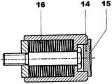
图2示意性地示出位于芯部2中的挤压弹簧装置6的基本结构。图2中可以看见杯形弹簧组16,其向绕组支撑件5施加预张力。挤压弹簧装置6的结构和操作方法对本领域技术人员而言是熟悉的,不需要对这一点具体说明。所述附图显示挤压弹簧装置6上的封盖盘14。重新调整装置7的接触表面8直接支撑在这个封盖盘14的接触表面15上。在最简单的情况下,挤压弹簧装置6和重新调整装置7的相互作用接触表面8和15可以是平面的。根据本发明的优选实施例,封盖盘14装配有凹形接触表面15,以便与重新调整装置7上的凸形接触表面8相互作用。FIG. 2 schematically shows the basic structure of the
图3是重新调整装置7的一个优选实施例。重新调整装置7显示其形式为螺钉或螺栓10。螺纹杆11和头部12之间的连接可以是刚性连接和铰接(或枢接)的(例如在具有铰接脚的情况下)。头部或接触板12用作用于弹簧装置6的封盖盘14的一个接触表面8,并且被定位成与弹簧装置6基本上对齐。接触表面8的凸型形状连同互补接触表面15的凹型形状具有自居中的效果。这不仅使组装简化,而且降低了在瞬间操作状态下发生侧向移位的风险。弹簧装置6的优选安装位置显示于图4和图5。这些附图显示螺钉或螺栓10被安装在支撑环9中。为此,支撑环9能够设置有带内螺纹的孔口。FIG. 3 is a preferred embodiment of the
在进行热处理前,螺钉和螺栓10被拧紧到支撑环9内,直到接触表面8完全与支撑环9的表面相齐平。在进行维修或热处理后,接触表面8的轴向高度能够通过旋转螺钉或螺栓10进行调整,以便通过这种方式向绕组施加所需的预应力。螺母13能够用于紧固螺栓10以防其旋转,并且以本身已知的方式(例如利用带齿的垫圈)进行紧固以防止发生意外地变松。Before heat treatment, the screws and
可替代地,通过旋转被布置在支撑环9和绕组支撑件5之间的螺母13,能够调整所述接触表面8的轴向高度。Alternatively, the axial height of said
支撑环9可以被封闭,并且如图1中所示可以具有抵靠在芯部2的径向外表面上的内周表面。便利地,多个重新调整装置7精确地分配布置在支撑环9的周边上,使得它们被定位成与挤压弹簧装置6直接相对。The support ring 9 may be closed and, as shown in FIG. 1 , may have an inner peripheral surface which rests on the radially outer surface of the
根据本发明的示例性实施例的上述描述仅旨在用于示例性目的,而非用于限制本发明的目的。特别的,多个优选示例性实施例,对本领域技术人员显而易见的是,在不偏离本发明的构思和保护范围的前提下,能够对其在形式和细节方面做出各种变化和修改。本发明的公开内容因此不应当认为是限制性的。相反,本发明的公开内容旨在说明所附权利要求书中所述的本发明的保护范围。The above descriptions according to the exemplary embodiments of the present invention are intended for illustrative purposes only, not for the purpose of limiting the present invention. In particular, it is obvious to those skilled in the art that various changes and modifications can be made in form and details of the preferred exemplary embodiments without departing from the concept and protection scope of the present invention. The disclosure of the invention should therefore not be considered as limiting. Rather, the disclosure of the invention is intended to be illustrative of the scope of the invention as described in the appended claims.
附图标记列表List of reference signs
1张紧装置1 tensioning device
2芯部2 cores
3芯部的端面3 end face of the core
4轴线方向(轴向)4 axis direction (axial)
5绕组支撑件5 winding supports
6挤压弹簧装置6 squeeze spring device
7重新调整装置7Readjust the device
8接触表面8 contact surfaces
9支撑环9 support ring
10螺栓10 bolts
11螺纹杆11 threaded rod
12头部12 heads
13螺母13 nuts
14封盖盘14 capping trays
15接触表面15 contact surface
16杯形弹簧组16 Cup Spring Sets
Claims (8)
Translated fromChineseApplications Claiming Priority (3)
| Application Number | Priority Date | Filing Date | Title |
|---|---|---|---|
| CH00363/09ACH700532A1 (en) | 2009-03-11 | 2009-03-11 | A device for axial clamping of a stator winding of an electrical machine. |
| CH00363/09 | 2009-03-11 | ||
| PCT/EP2010/052569WO2010102922A1 (en) | 2009-03-11 | 2010-03-01 | Device for axial tensioning of a stator coil of an electrical machine |
Publications (1)
| Publication Number | Publication Date |
|---|---|
| CN102349217Atrue CN102349217A (en) | 2012-02-08 |
Family
ID=40810077
Family Applications (1)
| Application Number | Title | Priority Date | Filing Date |
|---|---|---|---|
| CN2010800115058APendingCN102349217A (en) | 2009-03-11 | 2010-03-01 | Device for axial tensioning of a stator coil of an electrical machine |
Country Status (5)
| Country | Link |
|---|---|
| US (1) | US20120038241A1 (en) |
| CN (1) | CN102349217A (en) |
| CH (1) | CH700532A1 (en) |
| DE (1) | DE112010001167A5 (en) |
| WO (1) | WO2010102922A1 (en) |
Cited By (1)
| Publication number | Priority date | Publication date | Assignee | Title |
|---|---|---|---|---|
| CN106655654A (en)* | 2016-12-07 | 2017-05-10 | 哈尔滨电气动力装备有限公司 | Large stator coil compression tooling device for shielding motor |
Families Citing this family (1)
| Publication number | Priority date | Publication date | Assignee | Title |
|---|---|---|---|---|
| US11152830B2 (en)* | 2019-01-28 | 2021-10-19 | Siemens Energy, Inc. | Isolated bolting connection for a generator |
Citations (3)
| Publication number | Priority date | Publication date | Assignee | Title |
|---|---|---|---|---|
| CN1110023A (en)* | 1994-02-26 | 1995-10-11 | Abb管理有限公司 | Device for holding the ends of the turns of a stator winding in a dynamoelectric machine |
| WO2003077401A1 (en)* | 2002-03-12 | 2003-09-18 | Alstom Technology Ltd | Device and method for axially tensioning a stator winding |
| US20050029898A1 (en)* | 2003-07-05 | 2005-02-10 | Daniel Hediger | Apparatus for supporting a stator end winding |
Family Cites Families (2)
| Publication number | Priority date | Publication date | Assignee | Title |
|---|---|---|---|---|
| DE19755569A1 (en)* | 1997-12-15 | 1999-06-17 | Asea Brown Boveri | Electrical machine with a tensioned winding head |
| DE10310306A1 (en)* | 2002-03-12 | 2003-09-25 | Alstom Switzerland Ltd | Tensioning device for a stator winding especially for power station generators, has winding supports sprung connected to funnel shaped elements on the winding head |
- 2009
- 2009-03-11CHCH00363/09Apatent/CH700532A1/ennot_activeApplication Discontinuation
- 2010
- 2010-03-01DEDE112010001167Tpatent/DE112010001167A5/ennot_activeWithdrawn
- 2010-03-01WOPCT/EP2010/052569patent/WO2010102922A1/enactiveApplication Filing
- 2010-03-01CNCN2010800115058Apatent/CN102349217A/enactivePending
- 2011
- 2011-09-12USUS13/229,809patent/US20120038241A1/ennot_activeAbandoned
Patent Citations (3)
| Publication number | Priority date | Publication date | Assignee | Title |
|---|---|---|---|---|
| CN1110023A (en)* | 1994-02-26 | 1995-10-11 | Abb管理有限公司 | Device for holding the ends of the turns of a stator winding in a dynamoelectric machine |
| WO2003077401A1 (en)* | 2002-03-12 | 2003-09-18 | Alstom Technology Ltd | Device and method for axially tensioning a stator winding |
| US20050029898A1 (en)* | 2003-07-05 | 2005-02-10 | Daniel Hediger | Apparatus for supporting a stator end winding |
Cited By (1)
| Publication number | Priority date | Publication date | Assignee | Title |
|---|---|---|---|---|
| CN106655654A (en)* | 2016-12-07 | 2017-05-10 | 哈尔滨电气动力装备有限公司 | Large stator coil compression tooling device for shielding motor |
Also Published As
| Publication number | Publication date |
|---|---|
| DE112010001167A5 (en) | 2012-04-12 |
| CH700532A1 (en) | 2010-09-15 |
| WO2010102922A1 (en) | 2010-09-16 |
| US20120038241A1 (en) | 2012-02-16 |
Similar Documents
| Publication | Publication Date | Title |
|---|---|---|
| US10439463B2 (en) | Assembly and method for supporting generator stator end winding coils | |
| US8334613B2 (en) | Wind turbine generator and assembling method thereof | |
| CN110311493A (en) | Rotor-rotor shaft-assembly with material-fit connection | |
| CN102237750A (en) | Wind power turbine electric generator, and wind power turbine equipped with such an electric generator | |
| JP5010734B2 (en) | Wind power generator and assembly method thereof | |
| JPH03117339A (en) | Apparatus for fixing coil end of stator winding in dynamo electric machinery | |
| JPH0759286A (en) | Device for holding of winding end part of stator winding inside machine electric converter | |
| CN102349217A (en) | Device for axial tensioning of a stator coil of an electrical machine | |
| US20090104037A1 (en) | Fan Apparatus for a Cooking Device | |
| CN103875162B (en) | motor | |
| US8829759B2 (en) | Rotating electric machine with rotor including bolts | |
| JP6866279B2 (en) | Rotating machine | |
| CN109891709B (en) | Stator lamination stack segment plate, stator lamination stack, and generator and wind power plant having the same | |
| CN108712993B (en) | Winding machine | |
| US6965184B2 (en) | Apparatus for supporting a stator end winding | |
| US9035528B2 (en) | Press plate for tightening the metal sheets of a stator core of an electric machine | |
| RU2545184C2 (en) | Rotating electrical machine | |
| KR20160146743A (en) | An electric machine | |
| RU2550085C1 (en) | Mounting arrangement for stator end windings of turbine generator | |
| KR102219323B1 (en) | Fixed structure of spiral wind turbine blade | |
| JP6943147B2 (en) | Rotating electric rotor | |
| CN107078566B (en) | Component for motor | |
| JP2010246259A (en) | Stator fixing structure | |
| JP2015106991A (en) | Fitting method for rotor core |
Legal Events
| Date | Code | Title | Description |
|---|---|---|---|
| C06 | Publication | ||
| PB01 | Publication | ||
| C10 | Entry into substantive examination | ||
| SE01 | Entry into force of request for substantive examination | ||
| WD01 | Invention patent application deemed withdrawn after publication | ||
| WD01 | Invention patent application deemed withdrawn after publication | Application publication date:20120208 |