CN102348557A - Ink supply container - Google Patents
Ink supply containerDownload PDFInfo
- Publication number
- CN102348557A CN102348557ACN2009801579659ACN200980157965ACN102348557ACN 102348557 ACN102348557 ACN 102348557ACN 2009801579659 ACN2009801579659 ACN 2009801579659ACN 200980157965 ACN200980157965 ACN 200980157965ACN 102348557 ACN102348557 ACN 102348557A
- Authority
- CN
- China
- Prior art keywords
- container
- black liquid
- ink
- liquid supply
- compartment
- Prior art date
- Legal status (The legal status is an assumption and is not a legal conclusion. Google has not performed a legal analysis and makes no representation as to the accuracy of the status listed.)
- Pending
Links
Images


Classifications
- B—PERFORMING OPERATIONS; TRANSPORTING
- B41—PRINTING; LINING MACHINES; TYPEWRITERS; STAMPS
- B41J—TYPEWRITERS; SELECTIVE PRINTING MECHANISMS, i.e. MECHANISMS PRINTING OTHERWISE THAN FROM A FORME; CORRECTION OF TYPOGRAPHICAL ERRORS
- B41J2/00—Typewriters or selective printing mechanisms characterised by the printing or marking process for which they are designed
- B41J2/005—Typewriters or selective printing mechanisms characterised by the printing or marking process for which they are designed characterised by bringing liquid or particles selectively into contact with a printing material
- B41J2/01—Ink jet
- B41J2/17—Ink jet characterised by ink handling
- B41J2/175—Ink supply systems ; Circuit parts therefor
- B41J2/17503—Ink cartridges
- B41J2/17513—Inner structure
- B—PERFORMING OPERATIONS; TRANSPORTING
- B41—PRINTING; LINING MACHINES; TYPEWRITERS; STAMPS
- B41J—TYPEWRITERS; SELECTIVE PRINTING MECHANISMS, i.e. MECHANISMS PRINTING OTHERWISE THAN FROM A FORME; CORRECTION OF TYPOGRAPHICAL ERRORS
- B41J2/00—Typewriters or selective printing mechanisms characterised by the printing or marking process for which they are designed
- B41J2/005—Typewriters or selective printing mechanisms characterised by the printing or marking process for which they are designed characterised by bringing liquid or particles selectively into contact with a printing material
- B41J2/01—Ink jet
- B41J2/17—Ink jet characterised by ink handling
- B41J2/175—Ink supply systems ; Circuit parts therefor
- B41J2/17503—Ink cartridges
- B41J2/1752—Mounting within the printer
- B—PERFORMING OPERATIONS; TRANSPORTING
- B41—PRINTING; LINING MACHINES; TYPEWRITERS; STAMPS
- B41J—TYPEWRITERS; SELECTIVE PRINTING MECHANISMS, i.e. MECHANISMS PRINTING OTHERWISE THAN FROM A FORME; CORRECTION OF TYPOGRAPHICAL ERRORS
- B41J2/00—Typewriters or selective printing mechanisms characterised by the printing or marking process for which they are designed
- B41J2/005—Typewriters or selective printing mechanisms characterised by the printing or marking process for which they are designed characterised by bringing liquid or particles selectively into contact with a printing material
- B41J2/01—Ink jet
- B41J2/17—Ink jet characterised by ink handling
- B41J2/175—Ink supply systems ; Circuit parts therefor
- B41J2/17503—Ink cartridges
- B41J2/17553—Outer structure
Landscapes
- Ink Jet (AREA)
- Mechanical Pencils And Projecting And Retracting Systems Therefor, And Multi-System Writing Instruments (AREA)
Abstract
Translated fromChinese
Description
Translated fromChinese背景技术Background technique
彩色或黑色打印提供很大灵活性。但是,在一些情况下,诸如企业设置中,打印大多数是黑色的。相应地,企业通常有打印机或专用于黑色墨液的多功能机。在其它例子中,彩色打印机通常有几种颜色,由此打印处理颜色(process color)和至少一种黑色墨液。此黑色墨液用来打印黑色或还可与其它处理颜色一起使用。尽管可用彩色打印,但黑色打印比彩色打印要频繁得多。相应地,黑色墨液通常消耗得比彩色墨液要快。Printing in color or black offers great flexibility. However, in some cases, such as corporate settings, the print is mostly black. Accordingly, businesses often have printers or MFPs dedicated to black ink. In other examples, color printers typically have several colors whereby the print process color and at least one black ink. This black ink is used to print black or can also be used with other process colors. Although color printing is available, black printing is much more frequent than color printing. Accordingly, black ink is generally consumed faster than color ink.
然而,一旦打印机和其墨液供应机械装置提供给消费者,黑色墨液供应的容量相对于彩色墨液供应的容量大致是固定的。相应地,尽管消费者可以享有彩色或黑色打印的灵活性,但由于达到大量黑色打印必须使用的墨盒或墨液供应容器的数目,消费者在黑色打印的效率方面受到限制。However, once the printer and its ink supply mechanism are delivered to the consumer, the volume of the black ink supply is approximately fixed relative to the volume of the color ink supply. Accordingly, while the consumer may enjoy the flexibility of printing in color or black, the consumer is limited in the efficiency of black printing due to the number of ink cartridges or ink supply containers that must be used to achieve high volume black printing.
附图说明Description of drawings
包括附图以提供对实施例的进一步理解,且被并入此说明书中并构成此说明书的一部分。附图示出了实施例并与文字描述一起用来解释实施例的原理。通过参照下文的详细描述将更好地理解这些实施例,将容易地理解实施例。图中的元件不一定是彼此成比例绘制的。相似的附图标记指示相应的相似部件。The accompanying drawings are included to provide a further understanding of the embodiments, and are incorporated in and constitute a part of this specification. The drawings illustrate the embodiments and together with the description serve to explain the principles of the embodiments. Embodiments will be better understood and readily understood by referring to the following detailed description. The elements in the figures are not necessarily drawn to scale relative to each other. Like reference numerals designate corresponding like parts.
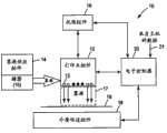
图1是根据本公开一个实施例的打印系统的示意图。FIG. 1 is a schematic diagram of a printing system according to one embodiment of the present disclosure.
图2是根据本公开一个实施例示出了打印头组件和墨液供应组件的前平面图。Figure 2 is a front plan view showing a printhead assembly and an ink supply assembly, according to one embodiment of the present disclosure.
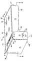
图3是根据本公开的一个实施例的墨液供应组件的透视图。Figure 3 is a perspective view of an ink supply assembly according to one embodiment of the present disclosure.
图4是根据本公开的一个实施例的打印组件的顶透视图。Figure 4 is a top perspective view of a printing assembly according to one embodiment of the present disclosure.
图5是根据本公开的一个实施例的大容量墨液供应容器的前透视图。5 is a front perspective view of a bulk ink supply container according to one embodiment of the present disclosure.
图6是根据本公开的一个实施例的降低容量的墨液供应容器的前透视图。6 is a front perspective view of a reduced volume ink supply container according to one embodiment of the present disclosure.
图7是根据本公开的一个实施例沿图5的线7-7截取的剖视图。7 is a cross-sectional view taken along line 7-7 of FIG. 5 according to one embodiment of the present disclosure.
图8是根据本公开的一个实施例沿图5的线8-8截取的剖视图。Figure 8 is a cross-sectional view taken along line 8-8 of Figure 5 according to one embodiment of the present disclosure.
图9是根据本公开的一个实施例沿图5的线9-9截取的剖视图。Figure 9 is a cross-sectional view taken along line 9-9 of Figure 5 according to one embodiment of the present disclosure.
图10是根据本公开的一个实施例的墨液供应组件和打印头组件的示意图。Figure 10 is a schematic illustration of an ink supply assembly and printhead assembly according to one embodiment of the present disclosure.
图11是根据本公开一个实施例示意性地示出了打印头组件和墨液供应组件的前平面图。Figure 11 is a front plan view schematically illustrating a printhead assembly and an ink supply assembly, according to one embodiment of the present disclosure.
图12是根据本公开一个实施例示意性地示出了打印头组件和墨液供应组件的前平面图。Figure 12 is a front plan view schematically illustrating a printhead assembly and an ink supply assembly, according to one embodiment of the present disclosure.
具体实施方式Detailed ways
在下文的详细描述中,参照构成本文一部分的附图,图中通过示意显示可以实践本发明的特定实施例。在此方面,方向性术语,诸如“顶部”、“底部”、“前部”、“后部”、“前面”、“后面”等参照被描述的图的取向使用。因为实施例的组件可以许多不同的取向定位,所以方向性术语是出于示意目的使用的,决不进行限制。要理解,可以使用其它实施例,在不偏离本发明的范围下可做出结构或逻辑改变。因此,下文的详细描述不是在限制意义上进行的,本发明的范围由所附权利要求书限定。In the following detailed description, reference is made to the accompanying drawings which form a part hereof, and which show by way of illustration specific embodiments in which the invention may be practiced. In this regard, directional terms such as "top", "bottom", "front", "rear", "front", "rear", etc. are used with reference to the orientation of the figures being described. Because components of an embodiment may be positioned in many different orientations, directional terms are used for purposes of illustration and in no way of limitation. It is to be understood that other embodiments may be utilized and structural or logical changes may be made without departing from the scope of the present invention. Therefore, the following detailed description is not to be taken in a limiting sense, but the scope of the invention is defined by the appended claims.
本公开的实施例提供一种墨液供应容器阵列,其中墨液供应容器,诸如第一墨液供应容器被配置基本大于其它墨液供应容器的体积的体积。在一个实施例中,第一容器包括第一部分和第二部分,这两部分都被配置成容纳墨液。第二部分大致垂直于第一部分延伸,并与第一部分流体连通。当所有的墨液供应容器设置在一起作为一个墨液供应组件时,第一容器的第二部分在其它墨液供应容器中的至少一些的顶部部分上延伸。Embodiments of the present disclosure provide an array of ink supply containers, wherein an ink supply container, such as a first ink supply container, is configured with a volume substantially greater than the volume of the other ink supply containers. In one embodiment, the first container includes a first portion and a second portion, both of which are configured to hold ink. The second portion extends generally perpendicular to and is in fluid communication with the first portion. When all ink supply containers are arranged together as one ink supply assembly, the second portion of the first container extends over top portions of at least some of the other ink supply containers.
通过此布局,第一容器容纳比墨液供应容器阵列中的其它容器基本更大的墨液体积。在一些实施例中,其它墨液供应容器的高度基本低于第一容器的第一部分的高度。换言之,其它墨液供应容器被配置成具有减小的尺寸或体积,以便将容器的第二部分容装在所述其它容器保持其常规尺寸或体积时所占据的空间内。With this arrangement, the first container holds a substantially greater volume of ink than the other containers in the array of ink supply containers. In some embodiments, the height of the other ink supply container is substantially lower than the height of the first portion of the first container. In other words, the other ink supply container is configured to have a reduced size or volume so as to accommodate the second portion of the container within the space that the other container would occupy while maintaining its normal size or volume.
在一些实施例中,第一容器容纳黑色墨液以在不从墨液供应组件中去掉彩色墨液供应容器下,提供超容量的黑色墨液供应容器。借助此布局,通过使用一组较短的彩色墨液供应容器和超大L形黑色墨液供应容器来简单代替,墨液供应组件被改进成对于彩色打印机能够获得大量的黑色打印。In some embodiments, the first container contains black ink to provide an overcapacity black ink supply container without removing the color ink supply container from the ink supply assembly. With this layout, the ink supply assembly is modified to enable high volume black printing for a color printer by simply replacing it with a set of shorter color ink supply containers and an oversized L-shaped black ink supply container.
与图1-12关联地描述这些实施例和附加实施例。These embodiments and additional embodiments are described in association with Figures 1-12.
图1示出了根据本公开的一个实施例的喷墨打印系统10。喷墨打印系统10包括喷墨打印头组件12、墨液供应组件14、墨盒组件16、介质传送组件18和电子控制器20。喷墨打印头组件12包括一个或多个打印头,它们通过孔或喷嘴13朝打印介质19喷射墨滴,以便打印到打印介质19上。打印介质19是任何类型的适当纸材料,诸如纸、卡片纸料、信封、标签、透明胶片、聚酯薄膜(Mylar)等等。通常,喷嘴13被设置成一列或多列或一行或多行,使得当喷墨打印头组件12和打印介质19相对彼此移动时,墨液从喷嘴13的适当顺序的喷射使字母、符号和/或其它图形或图像被打印在打印介质19上。Figure 1 illustrates an
墨液供应组件14给打印头组件12供应墨液,并包括用于储存墨液的储器15。因此,墨液从储器15流向喷墨打印头组件12。在一个实施例中,喷墨打印头组件12和墨液供应组件14一起容装于墨盒或笔中。在一些实施例中,墨液供应组件14与喷墨打印头组件12分离,但仍通过与墨液供应组件14的可释放连接直接将墨液传送到打印头组件12,墨液供应组件14直接安装在打印头组件12上,并至少部分由打印头组件12支撑。此实施例有时称作墨液供应组件14的轴上(on-axis)配置,后文将与至少图2、图11和图12关联地进行描述。The
然而,在其它实施例中,墨液供应组件14被定位在远离打印头组件12,墨液供应组件14通过供应管阵列将墨液传送到打印头组件12。此实施例有时称作墨液供应组件14的离轴(off-axis)配置,后文将与至少图10关联地进行描述。In other embodiments, however,
墨盒组件16相对于介质传送组件18定位喷墨打印头组件12,介质传送组件18相对于喷墨打印头组件12定位打印介质19。因此,打印区17被限定在喷墨打印头组件12和打印介质19之间的区域中喷嘴13的附近。在一个实施例中,喷墨打印头组件12是非扫描类型的打印头组件。因此,墨盒组件16在相对于介质传送组件18的预定位置固定喷墨打印头组件12。因此,介质传送组件18相对于喷墨打印头组件12推进或定位打印介质19。
电子控制器20与喷墨打印头组件12、介质传送组件18通信,在一个实施例中,与墨盒16通信。电子控制器20接收来自诸如计算机的主机系统的数据21,并包括用于暂时存储数据21的存储器。通常,数据21沿电子、红外、学或其它信息传送通道被发送到喷墨打印系统10。数据21代表例如待打印的图像、文档和/或文件。因此,数据21形成喷墨打印系统10的打印作业,包括一个或多个打印作业命令和/或命令参数。
在一个实施例中,电子控制器20提供对喷墨打印头组件12的控制,包括从喷嘴13喷射墨滴的定时控制。因此,电子控制器20对数据21进行操作,以限定在打印介质19上形成字母、符号和/或其它图形或图像的被喷射的墨滴的图案。定时控制以及因此的被喷射的墨滴的图案由打印作业命令和/或打印参数确定。在一个实施例中,形成电子控制器20的一部分的逻辑和驱动电路位于喷墨打印头组件12上。在另一个实施例中,逻辑和驱动电路位于喷墨打印头组件12远端。In one embodiment,
图2是根据本公开的一个实施例示出了打印组件50的侧视平面图。如图2所示,打印组件50包括打印头组件61、墨液供应组件71和墨盒52。墨盒52支撑打印头组件61和墨液供应组件71,其中打印头组件61包括打印头62、64阵列,墨液供应组件71包括墨液供应容器72、74的阵列70。在一个实施例中,打印头62形成于单个冲模上。如图2所示,每个相应的容器72、74可释放地连接到如图2所示的相应的一个打印头62、64的顶部部分。在一方面,每个容器72的大小和形状被制成基本直接在其各自的打印头62上方延伸。但是,在另一方面,容器74包括直接在其打印头64上方延伸的第一部分76,使得第一部分76在墨盒52内具有垂直取向。容器74的第二部分78相对于第一部分76的水平轴(由线A表示)大致水平或垂直地延伸。如图2所示,表示第二部分78和第一部分76之间不同的边界线由虚线82表示。第二部分78与第一部分76流体连通,以允许第一部分76和第二部分78之间有空气和墨液通道。FIG. 2 is a side plan view illustrating a
在一个实施例中,容器74的第一部分76具有基本大于容器72的高度(H2)的高度(H1)。尽管许多传统的墨液供应容器具有大致一致的高度,但在此实施例中,容器72的高度基本上低于它们常规配置的高度,以便容装大致水平延伸的第二部分78。在一方面,第二部分78具有高度(H3),容器72的高度(H2)和容器74的第二部分78的高度(H3)的和近似等于容器74的第一部分76的高度(H1)。在此布局中,墨液供应组件71提供增大(不同形状)的第一容器74和降低大小的容器72,同时大致保持墨液供应组件(在改变容器72、74的大小和/或形状之前)的整体大小或体积。In one embodiment, the
通过此布局,容器74包括额外特大容量的墨液供应容器,以提供经常使用的大体积的墨液,同时提供降低体积的彩色墨液。在一个实施例中,容器74包含黑色墨液,而容器72包含其它颜色的墨液。在一些其它实施例中,容器74包含非黑色的彩色墨液。With this arrangement,
图3是根据本公开的一个实施例墨液供应组件100的透视图。如图3所示,墨液供应组件100包括与之前与图2关联地描述的墨液供应组件71基本相同的特征和属性。Figure 3 is a perspective view of an
在一方面,容器74包括第一侧面75、第二侧面77、顶表面81和前表面107。此外,容器74的第一部分76包括底表面101,而第二部分78包括底表面79。在一方面,容器74的第一部分76包括形成于底表面101上的墨液口108和墨液水平窗口109A。In one aspect,
概括地说,容器72并排设置,大致与容器72成平行关系,容器72的大小能放置在容器74的第二部分78下面。借助此布局,容器72的高度(H2)和第二部分78的高度(H3)的和基于等于容器74的第一部分76的高度(H1)(如图2所示)。In general terms, the
在一方面,每个容器72包括形成于底表面104上的墨液口108和墨液水平窗口109B。此外,每个容器72的后部105和容器74的后部(在图3未显示)包括可释放的连接片122。In one aspect, each
在一些实施例中,每个容器72、74在其前表面107上包括大致T形的突出120,突出120被配置成可释放地连接到打印机的墨盒的往复部分(将与图4关联地进行描述)。要理解,突出120不严格限定为T形,可以采用适于可释放地锚定容器的其它形状。与片122配合,突出120确保每个容器72、74相对于(相应)打印头62、64适当定位并固定在墨盒52中。In some embodiments, each
如图3所示,此时嵌套在一起的容器72和容器74形成大致的矩形形状。在一些实施例中,要理解一个或多个容器72可包括突出120中的一个作为容器72的顶部部分103上的键(图3、图6),键被配置成与第一容器74的第二部分78的底表面79上的键孔往复配合,以可释放地相对于第一容器74以嵌套关系固定(一个或多个)容器72。而且,还要理解在容器72的顶表面103上形成键的实施例中,键包括各种形状中的任何一个形状,包括但不限于突出120的大致的T形配置。同样,第一容器74的第二部分78的底表面79中的键孔包括使键在容器72上往复运动的形状,诸如后面与图4关联描述的大致的T形凹槽157。借助此键-键孔布局,可省略容器72、74的前面部分107上的一个或多个突出120。在存在键-键孔布局的一个例子中,容器74的前面部分107上的突出120被省略,而容器72的前面部分107上的突出120被保留。在此例子中,由于通过突出120适当定位容器72,容器74被适当定位在墨盒52中。As shown in FIG. 3 , the nested
图4是根据本公开的一个实施例,包括墨盒152和墨液供应容器72阵列的打印头组件150的顶透视图。如图4所示,墨盒152包括第一端部170、第二端部172、第一侧面174和第二侧面176。在一方面,第二端部172包括限定一连串大致T形的凹槽157的内壁156,凹槽157被配置成可释放地接收容器72和74的T形突出120,从而相对于内壁156锚定另一容器72、74。此外,墨盒152被配置成支撑打印头62、64,使得墨液口160和每个打印头62、64的接口162(通过墨盒152的底板154)是可接近的,从而如图4所示连接到容器72、74的墨液口108和墨液水平窗口109A,109B。Figure 4 is a top perspective view of a
另一方面,图4示出了容器72在可释放安装位置位于墨盒152中,从而与其各自的打印头62(未显示)可操作地连通、连接。在一些实施例中,第二端部172还包括指示墨液供应容器72的具体颜色的色彩指示器178,其要安装在墨盒152上的指示位置。FIG. 4, on the other hand, shows the
图5是示出了根据本公开一个实施例的墨液供应容器的前透视图。在一个实施例中,图5中所示的容器74包括与之前与图2-4关联地描述的容器74至少基本相同的特征和属性。如图5所示,在其它之前指出的特征中,容器74包括顶表面81,顶表面包括填充口92阵列和迷宫排气机构94,迷宫排气机构94包括凹陷的排气路径95和排气口96。迷宫排气机构94实现用于提供排气同时使蒸发速率降低的已知技术。相应地,尽管为了图示简洁没有示出,迷宫排气机构94进一步包括由带或标签提供的被固定以在凹陷的排气路径95和排气口96上延伸的顶部部分。FIG. 5 is a front perspective view showing an ink supply container according to one embodiment of the present disclosure. In one embodiment, the
图6是示出了根据本公开一个实施例的墨液供应容器的透视图。在一个实施例中,图6中所示的容器72包括之前与图2-4关联地描述的容器72至少基本相同的特征和属性。如图6所示,在其它之前指出的特征中,容器72还包括填充口210和迷宫排气机构200,迷宫排气机构200包括凹陷的排气路径202和排气口204。在一方面,迷宫排气机构200并入与之前指出的迷宫排气机构94的带或标签相似的带或标签(未显示)。FIG. 6 is a perspective view illustrating an ink supply container according to one embodiment of the present disclosure. In one embodiment, the
图7-9是示意性地示出了容器74的各个内部特征和其它组件的容器74的剖视图。图7是根据本公开的一个实施例,沿图5的线7-7截取的剖视图,示意性地示出了容器74的第一部分76的组件和操作。如图7所示,概括地说,容器74包括第一隔室250和第二隔室252。第一隔室250通过第一毛细管介质270和第二毛细管介质272容纳一体积的墨液。第二毛细管介质272被直接定位在墨液口108上,其提供墨液到所连接的打印头(未显示)的连通路径。在一方面,墨液口108包括油芯元件109。7-9 are cross-sectional views of the
第二隔室252容纳自由体积的墨液292和空气294。第二隔室252与第一隔室通过壁285的间隙280流体连通,壁285将第一隔室250和第二隔室252分开。如图7示意性地示出的,与迷宫排气机构94配合,间隙280用作气泡机构的一部分以提供允许空气(由气泡287表示)取代从自由墨液隔室252中排出的流体的反压调节机制。在一个实施例中,填充口92包括用来密封地封闭口92从而封闭隔室252的软木塞295。The
在一方面,迷宫排气机构94定位在第一隔室250的顶部上面,以对第一隔室250通风,并对第二隔室252通风。借助第一隔室250和第二隔室252之间已经建立起来的压力梯度,压力以可控方式通过气泡间隙280逐渐释放,从而允许液体被吸入到各自的高、低毛细管介质272、270中,补充第一隔室250中的墨液。In one aspect, the
稍后在介绍图8-9的剖视图之后描述墨液供应容器74的大致操作。The general operation of the
图8是沿图5中的线8-8截取的容器74的剖视图。如图8所示,第一隔室250容纳第一毛细管介质270,而第二隔室252容纳自由墨液292。第二部分78限定容纳自由墨液310的腔室302,并通过口304与第二隔室252流体连通,从而根据需要允许墨液310自由流动到第二隔室252中。在一方面,腔室302由外壁300和将第一隔室250与第二部分78的腔室302隔开的内壁303限定。在另一方面,内壁303还将腔室302与第二隔室252隔开,除了在此区域308之外,内壁303限定口304,使得腔室302和第二隔室252之间能够进行流体连通。FIG. 8 is a cross-sectional view of
图9是沿图5中的线9-9截取的容器74的剖视图。如图9所示,第二部分78的第二隔室252和顶部部分81限定填充口阵列92。此外,图9示出了内壁303在第二部分78的第二隔室252和腔室302之间垂直延伸。在此区域中内壁303的底部部分307限定口304以允许自由墨液310在此通过进入到第二隔室252中,而在此区域中内壁303的上面部分305限定排气口320,其维持第二部分78的第二隔室252和腔室302之间的大致相等的空气压力。FIG. 9 is a cross-sectional view of
有了图5和图7-9所示的结构,在一个实施例中,墨液供应容器74的大致操作开始于容器74的第一部分76通过安装墨液口108可释放地连接到打印头的往复部分。当流体连通建立,打印使用容器74中的墨液时,首先从低毛细管介质270吸取墨液。在规定使用次数后,低毛细管介质270中的墨液耗尽,从而使空气暴露于至气泡间隙280的空气路径,使得在墨液被吸入第一隔室250中时,空气泡进入第二隔室252的自由墨液292中。本领域技术人员要理解气泡间隙280根据间隙280的大小和壁285上的模制特征控制预定的气泡压力。With the configuration shown in FIGS. 5 and 7-9, in one embodiment, the general operation of the
继续参照图7,借助通过释放到第二隔室252中的气泡287的反压的缓解,第二隔室252中的自由墨液292被吸入到高毛细管介质272中以通过墨液口108流到打印头中。自由墨液292还被吸入到低毛细管介质270中,从而阻挡到气泡间隙280的空气路径,这又使气泡机制不起作用,从而阻止未受控的墨液流292。而且,因为容器74的第二部分78提供具有自由墨液310的腔室302(图8-9),当墨液被吸入到高毛细管介质272中时,此自由墨液310流入第二隔室252中。一开始,容器74的第二部分78的腔室302中的墨液(图8-9)和第二隔室252中的墨液会表现为单个墨液体,直到墨液292的水平降低到第二部分78的底表面79下。此时,第二部分78的腔室302中几乎所有的墨液310都不见了。要理解墨液会以比墨液从第二部分78的腔室302流入第一部分76的第二隔室252的速率更低的速率从第二隔室252吸入到第一隔室250的低毛细管介质270和高毛细管介质272。With continued reference to FIG. 7 ,
关于第一部分76,通过第一隔室250和第二隔室252的交互作用,当气泡间隙280在通过口108消耗墨液而周期暴露时,自由墨液292会周期性吸入到低毛细管介质270和高毛细管介质272中。With respect to the
相应地,大致总结起来,通过容器74的第二部分78供应的额外体积的墨液与第二隔室252中的自由墨液292结合使用,以延长墨液供应容器74的使用寿命和容量。第二部分78中没有自由墨液310腔室302情况下,墨液供应容器74中的自由墨液292会局限于第二隔室252的体积。相应地,第二部分78提供基本上更大量的自由墨液,而不基本改变第一部分76的内部组件(包括相应的毛细管介质和反压机构)的操作。Accordingly, generally summarized, the additional volume of ink supplied through the
在一些实施例中,容器74的第一部分76省略低毛细管介质和自由墨液的第二隔室252,以提供更加简化的墨液供应容器。但是,要理解在改进的形式中,保留气泡机构(包括间隙280),或实现替代的反压调节器。在这些改进的实施例中,要了解适当的排气和反压机构被实现,来自第二部分78的自由墨液310会直接流入到第一隔室250和高毛细管介质272中。要进一步理解,在一些实施例中,毛细管介质、排气、反压和/或自由墨液隔室的其它布局用来提供墨液供应容器的第一部分76,其中第二部分78会在把来自容器74的第一部分76的墨液倒空的适当阶段,容易地将自由墨液供应到第一部分76中。In some embodiments, the
由于加入容器74的第二部分78,容器74提供比传统的墨液供应容器基本更大的墨液体积。在一个非限制性例子中,容器74提供比具有与第一部分76的大小相应大小的传统容器(即没有第二部分78)大3-4倍的自由墨液体积。Due to the addition of the
图10是根据本公开一个实施例示意性地示出了包括打印头组件61和墨液供应组件71的系统350的平面图。在一个实施例中,墨液供应组件71包括与之前与图2-9关联描述的墨液供应组件71基本相同的特征。FIG. 10 is a plan view schematically illustrating a
如图10所示,墨液供应组件71位于打印头组件61远端,导管354的阵列352在容器72、74和打印头62、64之间建立流体连通。此大致布局通常称作具有离轴墨液供应的打印头组件61。不过,与传统的离轴墨液供应系统不同,在此实施例中,墨液供应组件71包括超大容器74,容器74包括在其它容器72的顶部上方延伸的第二部分78,以为组件71提供更大容量的一种墨液颜色。As shown in FIG. 10 , an
要理解,在一些实施例中,示意性图示于图10中的离轴墨液供应系统350利用与远端定位的墨液供应容器72、74分离的泵和/或反压机构(类似于本领域已知的)。It is to be understood that in some embodiments, the off-axis
在一些实施例中,多于一个墨液供应容器配备在阵列的其它容器的顶部部分上方延伸的第二部分。例如,图11示出了根据本公开的一个实施例包括打印头组件61和轴上墨液供应组件401的系统400。在一个实施例中,除了墨液供应容器中有两个被配置为超大容器之外,系统400包括与系统50(之前与图2关联描述的)基本相同的特征和属性。具体地,墨液供应组件401包括容器72的阵列70,第一超大容器414和第二超大容器430。如图11所示,容器414和430同时存在或安装于墨盒52中。每个容器72、414、430可释放地连接到往复的打印头62、64。In some embodiments, more than one ink supply container is provided with a second portion extending over top portions of other containers of the array. For example, FIG. 11 illustrates a system 400 including a
第一超大容器414和第二超大容器430各自包括与(如之前与图2-9关联地描述的)容器74基本相同的特征和属性,除其相应的第二部分具有稍微不同的大小之外。具体是,第一超大容器414包括第一部分416和第二部分418,而第二超大容器430包括第一部分436和第二部分438。第一超大容器414的第一部分416具有与容器74的第一部分76基本相同的特征,而第二部分418具有与第二部分78基本相同的特征。不过,在一方面,容器414的第二部分418具有比容器74的第二部分78的长度(L1)(图2)短的长度(L2)。First oversized container 414 and second oversized container 430 each include substantially the same features and attributes as container 74 (as previously described in connection with FIGS. 2-9 ), except that their respective second portions have slightly different sizes. . Specifically, the first oversized container 414 includes a first portion 416 and a second portion 418 , while the second oversized container 430 includes a first portion 436 and a second portion 438 . The first portion 416 of the first oversized container 414 has substantially the same characteristics as the
在另一方面,第二超大容器430的第一部分436具有与容器74的第一部分76基本相同的特征,而第二部分438具有与第二部分78基本相同的特征。不过,在一方面,容器430的第二部分438具有比(图2)容器74的第二部分78的长度(L1)短并且比容器414的第二部分418的长度(L2)短的长度(L3)。相应地,当一起观察第一超大容器414和第二超大容器430时,可以看到第二部分418的长度(L2)适应第二超大容器430的第二部分438(具有长度L3)的存在。In another aspect, the first portion 436 of the second oversized container 430 has substantially the same characteristics as the
借此布局,墨液供应组件中超过一个容器具有基本比标称或常规大小的墨液供应容器更大并基本比阵列中的其它相应容器更大的体积或墨液容量。额外容量是通过排列各个容器414、430的第二部分418、438,以在另外的降低高度的容器72的顶部部分上方延伸获得的。With this arrangement, more than one container in the ink supply assembly has a substantially larger volume or ink capacity than the nominal or conventionally sized ink supply container and substantially larger than the other corresponding containers in the array. Additional capacity is obtained by arranging the second portion 418 , 438 of each container 414 , 430 to extend over the top portion of the additional reduced
最后,要理解在一些实施例中,墨液供应组件401除了具有与图10所示的墨液供应容器不同的组合之外以类似于图10显示的方式用作离轴墨液供应。Finally, it is to be understood that in some embodiments the ink supply assembly 401 functions as an off-axis ink supply in a manner similar to that shown in FIG. 10 , except with a different combination of ink supply containers than that shown in FIG. 10 .
图12示出了根据本公开一个实施例的包括打印头组件61和墨液供应组件451的系统450。在一个实施例中,系统450包括与(之前与图2关联地描述的)系统50基本相同的特征和属性,除了在系统450中,超大容器474被定位在墨液供应组件451的中间部分。在一方面,墨液供应组件451包括容器72的阵列70、大容器460、超大容器474。每个容器72、460、474分别可释放地连接到往复的打印头62、64。Figure 12 illustrates a system 450 including a
超大容器474包括与(之前与图2-9关联地描述的)容器74基本相同的特征和属性,除了具有稍微不同的大小,和具有两个从第一部分476的相对侧向外延伸的单独的第二部分478A,478B(不是具有一个第二部分67)。线482表示第一部分476和相应的第二部分478A,478B之间的边界。在一方面,超大容器474的第一部分476具有与容器74的第一部分476基本相同的特征,而第二部分478A,478B具有与容器74的第二部分78基本相同的特征(图2)。尽管第二部分478A,478B彼此分开,但第二部分478A,478B都容纳一定体积的自由墨液,并与第二部分476流体连通。在另一方面,第二部分478B具有比第二部分478A的长度(L2)短的长度(L3)。在其它实施例中,第二部分478A,478B在另外降低高度的容器72的顶部部分上方延伸。Oversized container 474 includes substantially the same features and attributes as container 74 (previously described in connection with FIGS. 2-9 ), except having a slightly different size, and having two separate Second part 478A, 478B (instead of having a second part 67). Line 482 represents the boundary between first portion 476 and corresponding second portion 478A, 478B. In one aspect, the first portion 476 of the oversized container 474 has substantially the same characteristics as the first portion 476 of the
在另一实施例中,容器460被改进为具有与另外降低高度的容器72的高度匹配的高度(H2)。此布局允许第二部分478B具有在改进的降低高度的容器460的顶部部分上延伸的更长的长度(L2而不是L3)。In another embodiment, container 460 is modified to have a height ( H2 ) that matches the height of otherwise reduced
最后,要理解的是,在一些实施例中,墨液供应组件451除了具有与图10所示的墨液供应容器不同的组合之外以类似于图10显示的方式用作离轴墨液供应。Finally, it is to be understood that in some embodiments the ink supply assembly 451 functions as an off-axis ink supply in a manner similar to that shown in FIG. .
要理解,除非另外指出,否则本文描述的各个示例性实施例的特征可彼此组合。It is to be understood that the features of the various exemplary embodiments described herein may be combined with each other unless otherwise indicated.
本公开的实施例提供改进墨液供应组件以基本提高墨液供应组件中至少一种颜色墨液的容量的各种方式,而不用改变打印头组件或不用改变支撑墨液供应容器的墨盒。而且,在至少一个实施例中,至少一种墨液的此提高的容量是在不去掉墨液供应组件的其它颜色的情况下获得的。Embodiments of the present disclosure provide various ways of modifying an ink supply assembly to substantially increase the capacity of at least one color of ink in the ink supply assembly without changing the printhead assembly or without changing the ink cartridges that support the ink supply containers. Moreover, in at least one embodiment, this increased capacity of at least one ink is obtained without removing other colors of the ink supply assembly.
尽管在本公开中已经图示并描述了具体的实施例,但本领域技术人员会认识到在不偏离本发明的范围下可用各种替代和/或等同实施方式替代所显示和描述的具体实施例。此应用旨在覆盖本文讨论的具体实施例的任何改进或变化。因此,旨在本发明仅由权利要求书和其等同物限定。Although specific embodiments have been illustrated and described in this disclosure, those skilled in the art will recognize that various alternatives and/or equivalents may be used in place of the specific implementations shown and described without departing from the scope of the invention. example. This application is intended to cover any adaptations or variations of the specific embodiments discussed herein. Therefore, it is intended that this invention be limited only by the claims and the equivalents thereof.
Claims (15)
Priority Applications (1)
| Application Number | Priority Date | Filing Date | Title |
|---|---|---|---|
| CN201610757537.1ACN106313903A (en) | 2009-03-09 | 2009-03-09 | Ink supply container |
Applications Claiming Priority (1)
| Application Number | Priority Date | Filing Date | Title |
|---|---|---|---|
| PCT/US2009/036555WO2010104500A2 (en) | 2009-03-09 | 2009-03-09 | Ink supply container |
Related Child Applications (1)
| Application Number | Title | Priority Date | Filing Date |
|---|---|---|---|
| CN201610757537.1ADivisionCN106313903A (en) | 2009-03-09 | 2009-03-09 | Ink supply container |
Publications (1)
| Publication Number | Publication Date |
|---|---|
| CN102348557Atrue CN102348557A (en) | 2012-02-08 |
Family
ID=42728983
Family Applications (1)
| Application Number | Title | Priority Date | Filing Date |
|---|---|---|---|
| CN2009801579659APendingCN102348557A (en) | 2009-03-09 | 2009-03-09 | Ink supply container |
Country Status (5)
| Country | Link |
|---|---|
| US (1) | US8657424B2 (en) |
| EP (1) | EP2406082B1 (en) |
| CN (1) | CN102348557A (en) |
| BR (1) | BRPI0923982A2 (en) |
| WO (1) | WO2010104500A2 (en) |
Cited By (2)
| Publication number | Priority date | Publication date | Assignee | Title |
|---|---|---|---|---|
| CN112123944A (en)* | 2020-10-20 | 2020-12-25 | 东莞市图创智能制造有限公司 | Ink cartridges and printing equipment |
| US11810562B2 (en) | 2014-05-30 | 2023-11-07 | Apple Inc. | Reducing the need for manual start/end-pointing and trigger phrases |
Families Citing this family (6)
| Publication number | Priority date | Publication date | Assignee | Title |
|---|---|---|---|---|
| WO2013115753A2 (en)* | 2010-11-30 | 2013-08-08 | Hewlett-Packard Development Company, L.P. | Fluid container having first and second key sets |
| KR101855968B1 (en) | 2011-01-07 | 2018-05-09 | 휴렛-팩커드 디벨롭먼트 컴퍼니, 엘.피. | Fluid container having plurality of chambers and valves |
| US9233545B2 (en)* | 2013-09-27 | 2016-01-12 | Brother Kogyo Kabushiki Kaisha | Liquid ejection device |
| US9738084B2 (en)* | 2014-01-21 | 2017-08-22 | Hewlett-Packard Development Company, L.P. | Replaceable liquid supply having cut outs and latch |
| CN106232368B (en) | 2014-06-26 | 2018-04-06 | 惠普发展公司有限责任合伙企业 | container assembly |
| JP6497152B2 (en)* | 2015-03-19 | 2019-04-10 | セイコーエプソン株式会社 | Tank, tank unit, liquid injection system |
Citations (5)
| Publication number | Priority date | Publication date | Assignee | Title |
|---|---|---|---|---|
| JPH0760983A (en)* | 1993-08-30 | 1995-03-07 | Canon Inc | Inkjet ink tank |
| JPH07137298A (en)* | 1993-11-16 | 1995-05-30 | Tec Corp | Ink jet printer |
| US6012808A (en)* | 1992-07-24 | 2000-01-11 | Canon Kabushiki Kaisha | Ink container, ink and ink jet recording apparatus using ink container |
| US6152558A (en)* | 1997-02-12 | 2000-11-28 | Oki Data Corporation | Ink jet printer |
| US20030076391A1 (en)* | 2001-10-24 | 2003-04-24 | Wilson John F. | Supply adaptor for an on-axis printer |
Family Cites Families (19)
| Publication number | Priority date | Publication date | Assignee | Title |
|---|---|---|---|---|
| US5408746A (en)* | 1993-04-30 | 1995-04-25 | Hewlett-Packard Company | Datum formation for improved alignment of multiple nozzle members in a printer |
| US6033064A (en) | 1994-10-31 | 2000-03-07 | Hewlett-Packard Company | Inkjet printer with off-axis ink supply |
| US5995721A (en) | 1996-10-18 | 1999-11-30 | Xerox Corporation | Distributed printing system |
| US6095643A (en) | 1998-05-07 | 2000-08-01 | Lexmark International, Inc. | Refillable disposable inkjet cartridge with foam-filled and free ink reservoirs |
| US6019459A (en) | 1998-09-10 | 2000-02-01 | Hewlett-Packard Company | Dual capillarity ink accumulator for ink-jet |
| JP4532705B2 (en) | 2000-09-06 | 2010-08-25 | キヤノン株式会社 | Inkjet recording head |
| JP4789315B2 (en)* | 2000-10-04 | 2011-10-12 | キヤノン株式会社 | Ink tank module and inkjet recording apparatus |
| US6742880B2 (en) | 2000-10-06 | 2004-06-01 | Nu-Kote International, Inc. | Dual chamber cartridge |
| EP1201438A3 (en)* | 2000-10-11 | 2002-06-26 | Seiko Epson Corporation | Ink cartridge and inkjet printer |
| CA2379725C (en) | 2001-04-03 | 2007-06-12 | Seiko Epson Corporation | Ink cartridge |
| JP3970119B2 (en) | 2002-07-19 | 2007-09-05 | キヤノン株式会社 | Ink jet recording head and recording apparatus using the ink jet recording head |
| KR100452851B1 (en) | 2002-10-23 | 2004-10-14 | 삼성전자주식회사 | an ink cartridge having a proper negative pressure |
| US7152957B2 (en) | 2002-12-18 | 2006-12-26 | Canon Kabushiki Kaisha | Recording device board having a plurality of bumps for connecting an electrode pad and an electrode lead, liquid ejection head, and manufacturing method for the same |
| JP4381072B2 (en) | 2003-09-11 | 2009-12-09 | ブラザー工業株式会社 | ink cartridge |
| US7399073B2 (en) | 2005-05-19 | 2008-07-15 | Hewlett-Packard Development Company, L.P. | Ink supply |
| US7828421B2 (en) | 2005-09-29 | 2010-11-09 | Brother Kogyo Kabushiki Kaisha | Ink cartridge arrangements |
| US20070103520A1 (en) | 2005-11-04 | 2007-05-10 | U Colour International Co., Ltd. | Interior pressure self-adjustable ink supply cartridge structure |
| US7559635B2 (en) | 2006-05-17 | 2009-07-14 | Lexmark International, Inc. | Apparatus for facilitating determination of proper supply cartridge installation |
| US8197055B2 (en) | 2006-11-29 | 2012-06-12 | Seiko Epson Corporation | Patterning method, droplet discharging device and circuit board |
- 2009
- 2009-03-09BRBRPI0923982Apatent/BRPI0923982A2/ennot_activeIP Right Cessation
- 2009-03-09USUS13/255,275patent/US8657424B2/ennot_activeExpired - Fee Related
- 2009-03-09WOPCT/US2009/036555patent/WO2010104500A2/enactiveApplication Filing
- 2009-03-09EPEP09841613.4Apatent/EP2406082B1/ennot_activeNot-in-force
- 2009-03-09CNCN2009801579659Apatent/CN102348557A/enactivePending
Patent Citations (5)
| Publication number | Priority date | Publication date | Assignee | Title |
|---|---|---|---|---|
| US6012808A (en)* | 1992-07-24 | 2000-01-11 | Canon Kabushiki Kaisha | Ink container, ink and ink jet recording apparatus using ink container |
| JPH0760983A (en)* | 1993-08-30 | 1995-03-07 | Canon Inc | Inkjet ink tank |
| JPH07137298A (en)* | 1993-11-16 | 1995-05-30 | Tec Corp | Ink jet printer |
| US6152558A (en)* | 1997-02-12 | 2000-11-28 | Oki Data Corporation | Ink jet printer |
| US20030076391A1 (en)* | 2001-10-24 | 2003-04-24 | Wilson John F. | Supply adaptor for an on-axis printer |
Cited By (2)
| Publication number | Priority date | Publication date | Assignee | Title |
|---|---|---|---|---|
| US11810562B2 (en) | 2014-05-30 | 2023-11-07 | Apple Inc. | Reducing the need for manual start/end-pointing and trigger phrases |
| CN112123944A (en)* | 2020-10-20 | 2020-12-25 | 东莞市图创智能制造有限公司 | Ink cartridges and printing equipment |
Also Published As
| Publication number | Publication date |
|---|---|
| EP2406082A2 (en) | 2012-01-18 |
| HK1161190A1 (en) | 2012-08-24 |
| WO2010104500A3 (en) | 2011-08-11 |
| EP2406082B1 (en) | 2015-11-11 |
| US8657424B2 (en) | 2014-02-25 |
| WO2010104500A2 (en) | 2010-09-16 |
| BRPI0923982A2 (en) | 2016-01-19 |
| EP2406082A4 (en) | 2013-05-15 |
| WO2010104500A8 (en) | 2011-11-17 |
| US20120001990A1 (en) | 2012-01-05 |
Similar Documents
| Publication | Publication Date | Title |
|---|---|---|
| CN109927414B (en) | Printing apparatus and liquid storage container | |
| KR100346533B1 (en) | Ink Tank Cartridges for Ink-Jet Recording Devices | |
| US9592675B2 (en) | Liquid fill container | |
| CN102348557A (en) | Ink supply container | |
| CA2441977C (en) | Dual serial pressure regulator for ink-jet printing | |
| CN100421951C (en) | Method and apparatus for providing ink container extraction characteristics to a printing system | |
| US7025448B2 (en) | Fluid interconnect in a replaceable ink reservoir for pigmented ink | |
| KR100722918B1 (en) | Liquid container and printing apparatus using the same | |
| EP3718772B1 (en) | Inkjet printing apparatus and ink tank | |
| CN103568570B (en) | The injection fitting of printing material and method for implanting | |
| CN101850661B (en) | Attachment and liquid supplying device | |
| JP2007296795A (en) | Liquid supply system and ink jet recording apparatus | |
| US9132649B2 (en) | Removable guide element | |
| EP2582525B1 (en) | Ink supply reservoir | |
| JP2006212845A (en) | Liquid storage container and liquid supply device | |
| US8141997B2 (en) | Ink supply system | |
| JP2004090414A (en) | Liquid storage cartridge, ink cartridge | |
| HK1161190B (en) | Ink supply container | |
| CN106313903A (en) | Ink supply container | |
| CN101081563A (en) | Ink tank cartridge for a printer | |
| JP4013743B2 (en) | Liquid ejector | |
| US20050088496A1 (en) | Ink refilling cap | |
| HK1110276A (en) | An ink tank cartridge for an ink-jet type recording apparatus |
Legal Events
| Date | Code | Title | Description |
|---|---|---|---|
| C06 | Publication | ||
| PB01 | Publication | ||
| C10 | Entry into substantive examination | ||
| SE01 | Entry into force of request for substantive examination | ||
| C12 | Rejection of a patent application after its publication | ||
| RJ01 | Rejection of invention patent application after publication | Application publication date:20120208 |