CN102338345B - Lenticular lens group device and backlight module used therefor - Google Patents
Lenticular lens group device and backlight module used thereforDownload PDFInfo
- Publication number
- CN102338345B CN102338345BCN 201010234299CN201010234299ACN102338345BCN 102338345 BCN102338345 BCN 102338345BCN 201010234299CN201010234299CN 201010234299CN 201010234299 ACN201010234299 ACN 201010234299ACN 102338345 BCN102338345 BCN 102338345B
- Authority
- CN
- China
- Prior art keywords
- lenticular lens
- refractive index
- critical angle
- layer
- light
- Prior art date
- Legal status (The legal status is an assumption and is not a legal conclusion. Google has not performed a legal analysis and makes no representation as to the accuracy of the status listed.)
- Active
Links
- 230000003287optical effectEffects0.000claimsdescription39
- NCGICGYLBXGBGN-UHFFFAOYSA-N3-morpholin-4-yl-1-oxa-3-azonia-2-azanidacyclopent-3-en-5-imine;hydrochlorideChemical compoundCl.[N-]1OC(=N)C=[N+]1N1CCOCC1NCGICGYLBXGBGN-UHFFFAOYSA-N0.000claimsdescription17
- 239000004417polycarbonateSubstances0.000claimsdescription13
- 229920000515polycarbonatePolymers0.000claimsdescription13
- 229920003229poly(methyl methacrylate)Polymers0.000claimsdescription12
- 239000004926polymethyl methacrylateSubstances0.000claimsdescription12
- 238000009792diffusion processMethods0.000claimsdescription10
- 239000004793PolystyreneSubstances0.000claimsdescription9
- 229920000139polyethylene terephthalatePolymers0.000claimsdescription9
- 239000005020polyethylene terephthalateSubstances0.000claimsdescription9
- 101100384865Neurospora crassa (strain ATCC 24698 / 74-OR23-1A / CBS 708.71 / DSM 1257 / FGSC 987) cot-1 geneProteins0.000claimsdescription8
- 229920000089Cyclic olefin copolymerPolymers0.000claimsdescription6
- 239000004713Cyclic olefin copolymerSubstances0.000claimsdescription6
- NNLVGZFZQQXQNW-ADJNRHBOSA-N[(2r,3r,4s,5r,6s)-4,5-diacetyloxy-3-[(2s,3r,4s,5r,6r)-3,4,5-triacetyloxy-6-(acetyloxymethyl)oxan-2-yl]oxy-6-[(2r,3r,4s,5r,6s)-4,5,6-triacetyloxy-2-(acetyloxymethyl)oxan-3-yl]oxyoxan-2-yl]methyl acetateChemical compoundO([C@@H]1O[C@@H]([C@H]([C@H](OC(C)=O)[C@H]1OC(C)=O)O[C@H]1[C@@H]([C@@H](OC(C)=O)[C@H](OC(C)=O)[C@@H](COC(C)=O)O1)OC(C)=O)COC(=O)C)[C@@H]1[C@@H](COC(C)=O)O[C@@H](OC(C)=O)[C@H](OC(C)=O)[C@H]1OC(C)=ONNLVGZFZQQXQNW-ADJNRHBOSA-N0.000claimsdescription6
- 229920002223polystyrenePolymers0.000claimsdescription6
- 229920001577copolymerPolymers0.000claimsdescription5
- -1polyethylene terephthalatePolymers0.000claimsdescription5
- 238000000034methodMethods0.000claimsdescription3
- ADFPJHOAARPYLP-UHFFFAOYSA-Nmethyl 2-methylprop-2-enoate;styreneChemical compoundCOC(=O)C(C)=C.C=CC1=CC=CC=C1ADFPJHOAARPYLP-UHFFFAOYSA-N0.000claimsdescription3
- 238000010586diagramMethods0.000description14
- 238000002474experimental methodMethods0.000description9
- 238000002834transmittanceMethods0.000description9
- 230000000694effectsEffects0.000description8
- 238000013461designMethods0.000description4
- 239000004973liquid crystal related substanceSubstances0.000description4
- 230000005540biological transmissionEffects0.000description3
- 238000005520cutting processMethods0.000description3
- 238000004519manufacturing processMethods0.000description3
- 238000004064recyclingMethods0.000description3
- 239000000463materialSubstances0.000description2
- 238000004220aggregationMethods0.000description1
- 230000002776aggregationEffects0.000description1
- 238000013459approachMethods0.000description1
- 230000003247decreasing effectEffects0.000description1
- 238000012986modificationMethods0.000description1
- 230000004048modificationEffects0.000description1
- 229920003023plasticPolymers0.000description1
- 239000004033plasticSubstances0.000description1
- 230000005855radiationEffects0.000description1
- 238000012216screeningMethods0.000description1
Images


Landscapes
- Planar Illumination Modules (AREA)
Abstract


Description
Translated fromChinese技术领域technical field
本发明涉及一种透镜组、侧光式背光模块及直下式背光模块,特别涉及一种柱状透镜组装置,及其使用的侧光式背光模块与直下式背光模块。The invention relates to a lens group, a side-light type backlight module and a direct-type backlight module, in particular to a cylindrical lens group device, and the side-light type backlight module and the direct-type backlight module used therein.
背景技术Background technique
近年来,传统的阴极射线管显示器(即俗称的CRT显示器)已渐渐地被液晶显示器所取代,主要原因在于液晶显示器所释放出的辐射量远远小于CRT显示器,另外,液晶显示器在这几年的制造成本已有显着地降低,这也是液晶显示器逐渐成为电视或计算机屏幕市场的主流的原因。In recent years, traditional cathode ray tube displays (commonly known as CRT displays) have been gradually replaced by liquid crystal displays. The main reason is that the amount of radiation emitted by liquid crystal displays is far less than that of CRT displays. The manufacturing cost of LCDs has decreased significantly, which is why LCD monitors are gradually becoming the mainstream of the TV or computer screen market.
液晶显示器可区分为液晶面板及背光模块两大部份,而背光模块通常会按照屏幕的大小尺寸而分别使用直下式背光模块或侧光式背光模块。一般而言,无论是直下式背光模块或侧光式背光模块,都会通过通过结构的设计使光线反复地回收与利用,以避免光能量的损耗;然后,再透过增亮膜将光线的光学路径聚集,用以提高光强度中心增益值。A liquid crystal display can be divided into two parts: a liquid crystal panel and a backlight module, and the backlight module usually uses a direct-lit backlight module or an edge-lit backlight module according to the size of the screen. Generally speaking, whether it is a direct-lit backlight module or an edge-lit backlight module, the light will be recycled and utilized repeatedly through the design of the structure to avoid the loss of light energy; Path aggregation, used to increase the light intensity center gain value.
传统上,增亮膜均使用单一介质。依据Fresnel equation公式:Traditionally, brightness enhancement films use a single medium. According to the Fresnel equation formula:
其中,T为透光率,R为反射率,nA、nB分别为两互相接触之介质的折射率。若以聚碳酸酯(Polycarbonate,PC)为介质的增亮膜为例:PC的折射率为1.586,空气的折射率为1.0,该增亮膜在与空气相交处的界面之总透光率为:Among them, T is the light transmittance, R is the reflectance, nA and nB are the refractive indices of the two media in contact with each other. Taking the brightness enhancement film of polycarbonate (PC) as an example: the refractive index of PC is 1.586, and the refractive index of air is 1.0. The total light transmittance of the interface where the brightness enhancement film intersects with air is :
故,所有灯源的光能量有将近10%的损耗无法被利用。此外,除了折射率差异所造成的Fresnel损耗之外,还有增亮膜出光面的微结构的外形,若设计不当,会直接导致光线无效的折射或反射,使光线无法集中于出光视角之处,因此出光视角之光强度中心增益值也无法进一步提升。Therefore, nearly 10% of the light energy of all light sources is lost and cannot be utilized. In addition, in addition to the Fresnel loss caused by the difference in refractive index, there is also the shape of the microstructure on the light-emitting surface of the brightness enhancement film. If the design is not proper, it will directly lead to ineffective refraction or reflection of light, making it impossible for the light to be concentrated at the light-emitting angle. , so the central gain value of the light intensity of the light-emitting angle of view cannot be further improved.
因此,如何提升光能量的利用率,降低损耗,并且提高出光视角之光强度中心增益值,是本领域具有通常知识者努力的目标。Therefore, how to improve the utilization rate of light energy, reduce the loss, and increase the center gain value of the light intensity of the light output viewing angle is the goal of efforts of those skilled in the art.
发明内容Contents of the invention
本发明主要目的在于提升直下式背光模块及侧光式背光模块的光能量的利用率,降低Fresnel损耗。The main purpose of the present invention is to improve the utilization rate of light energy of the direct type backlight module and the edge type backlight module, and reduce the Fresnel loss.
本发明另一目的在于提高透镜组出光视角的光强度中心增益值。Another object of the present invention is to increase the central gain value of the light intensity of the light emitting angle of view of the lens group.
为达上述目的,本发明提供一种柱状透镜组装置,其包括有一柱状透镜层及一第二折射率层。其中,该柱状透镜层具有一第一折射率(n1),该柱状透镜层具有多个柱状透镜排列位于一谷面上,该柱状透镜更包括有相距一高度(H)之一波峰及一波谷,该波谷位于该谷面上,该波峰与该波谷间具有一曲面结构,该曲面结构具有一曲率半径(R),该波峰及另一波峰相距有一宽度(P),该柱状透镜层定义有一法线方向以及一第一临界角(θ1c),该法线方向与该谷面相垂直,该第一临界角(θ1c)是与该法线方向的夹角,To achieve the above purpose, the present invention provides a lenticular lens assembly, which includes a lenticular lens layer and a second refractive index layer. Wherein, the lenticular lens layer has a first refractive index (n1 ), and the lenticular lens layer has a plurality of lenticular lenses arranged on a valley surface, and the lenticular lens further includes a peak at a height (H) and a The trough, the trough is located on the trough surface, there is a curved surface structure between the peak and the trough, the curved surface structure has a radius of curvature (R), the peak and another peak are separated by a width (P), and the lenticular lens layer defines There is a normal direction and a first critical angle (θ1c ), the normal direction is perpendicular to the valley surface, the first critical angle (θ1c ) is the included angle with the normal direction,
该第一临界角
该高度(H)须符合:
该柱状透镜的圆锥常数(K)之范围介于-2.1~-1.5。该第二折射率层具有一第二折射率(n2),且与该柱状透镜层相连接,该第一折射率(n1)大于该第二折射率(n2),该第二折射率层定义有一第二临界角(θ2c),该第二临界角(θ2c)是与该法线方向的夹角,The conic constant (K) of the lenticular lens ranges from -2.1 to -1.5. The second refractive index layer has a second refractive index (n2 ) and is connected to the lenticular lens layer, the first refractive index (n1 ) is greater than the second refractive index (n2 ), the second refractive index The rate layer is defined to have a second critical angle (θ2c ), the second critical angle (θ2c ) is the included angle with the normal direction,
该第二临界角
该每一柱状透镜、该第一临界角以及该第二临界角符合公式:Each lenticular lens, the first critical angle, and the second critical angle satisfy the formula:
由此,该柱状透镜增亮膜可用以降低光线的传输损耗,并提高出光强度中心增益值。Therefore, the brightness enhancement film of the lenticular lens can be used to reduce the transmission loss of the light, and increase the center gain value of the light intensity.
如上所述的柱状透镜组的装置,其中,自该柱状透镜层与该第二折射率层相连接处相距该谷面具有一第一厚度(t1)以及自该柱状透镜层与该第二折射率层相连接处相距该第二折射率层之一另一侧具有一第二厚度(t2),则该第二厚度与该第一厚度的比值最佳范围为0.035~0.084。由此,该柱状透镜增亮膜的光强度最大会比公知增亮膜的光强度高出1.5%。The device of the lenticular lens group as described above, wherein the valley surface has a first thickness (t 1 ) from the junction of the lenticular lens layer and the second refractive index layer and has a first thickness (t1 ) from the lenticular lens layer to the second refractive index layer. The connecting portion of the refractive index layer has a second thickness (t2 ) on the other side of the second refractive index layer, and the ratio of the second thickness to the first thickness is preferably in the range of 0.035˜0.084. Therefore, the light intensity of the lenticular lens brightness enhancement film is at most 1.5% higher than that of the known brightness enhancement film.
如上所述的柱状透镜组装置,其中,K=-1.65~-2,H/P=0.42~0.498,由此,具有双曲线轮廓的曲面结构可使该柱状透镜增亮膜的光强度中心增益值比传统增亮膜增加将近4.4%。The above-mentioned lenticular lens group device, wherein, K=-1.65~-2, H/P=0.42~0.498, thus, the curved surface structure with hyperbolic contour can make the light intensity center gain of the lenticular lens brightness enhancement film The value is nearly 4.4% higher than the traditional brightness enhancement film.
如上所述的柱状透镜组装置,其中,该多个柱状透镜层为二维形状或三维形状。The lenticular lens group device as described above, wherein the plurality of lenticular lens layers are in a two-dimensional shape or a three-dimensional shape.
如上所述的柱状透镜组装置,其中,更包有一第三折射率层,其具有一第三折射率(n3),该第三折射率(n3)小于该第一折射率(n1)以及小于该第二折射率(n2)。The above-mentioned lenticular lens group device, wherein, it further includes a third refractive index layer, which has a third refractive index (n3 ), and the third refractive index (n3 ) is smaller than the first refractive index (n1 ) and less than the second refractive index (n2 ).
如上所述的柱状透镜组装置,其中,该柱状透镜层以或该第二折射率层的材质为聚乙烯对苯二甲酸酯(Polyethylene Terephthalate,PET)、聚碳酸酯(Polycarbonate,PC)、三醋酸纤维素(Tri-acetylCellulose,TAC)、聚甲基丙烯酸甲酯(Polymethylmethacrylate,PMMA)、甲基丙烯酸甲酯-苯乙烯共聚物(Methylmethacrylatestyrene)、聚苯乙烯(Polystyrene,PS)或环烯共聚物(Cyclic OlefinCopolymer,COC)。The lenticular lens group device as described above, wherein, the material of the lenticular lens layer or the second refractive index layer is polyethylene terephthalate (Polyethylene Terephthalate, PET), polycarbonate (Polycarbonate, PC), Tri-acetylcellulose (TAC), polymethylmethacrylate (Polymethylmethacrylate, PMMA), methylmethacrylate-styrene copolymer (Methylmethacrylatestyrene), polystyrene (Polystyrene, PS) or cycloolefin copolymer (Cyclic Olefin Copolymer, COC).
为达上述目的,本发明提供一种侧光式背光模块,其具有一入射光、一第一光学路径以及一第二光学路径,该侧光式背光模块包含有一光源、一导光板、一反射片及一前述的柱状透镜组装置。其中,该光源用以发射该入射光;该导光板设置该光源之一侧,且该导光板传导该入射光形成该光学路径;该反射片设置该导光板下方;该柱状透镜组装置设置该导光板上方以接收该光学路径;To achieve the above object, the present invention provides an edge-lit backlight module, which has an incident light, a first optical path, and a second optical path, and the edge-lit backlight module includes a light source, a light guide plate, a reflector sheet and a aforementioned lenticular lens group device. Wherein, the light source is used to emit the incident light; the light guide plate is arranged on one side of the light source, and the light guide plate conducts the incident light to form the optical path; the reflective sheet is arranged under the light guide plate; the cylindrical lens group device is provided with the above the light guide plate to receive the optical path;
一柱状透镜组装置,设置该导光板上方以接收该光学路径,该柱状透镜组装置还包含:一柱状透镜层,具有一第一折射率(n1),该柱状透镜层具有多个柱状透镜排列位于一谷面上,该柱状透镜更包括有相距一高度(H)的一波峰及一波谷,该波谷皆位于该谷面上,该波峰与该波谷间具有一曲面结构,该曲面结构具有一曲率半径(R),该波峰及另一波峰相距有一宽度(P),该柱状透镜层定义有一法线方向以及一第一临界角(θ1c),该法线方向与该谷面相垂直,该第一临界角(θ1c)是与该法线方向的夹角,该第一临界角

该柱状透镜之一圆锥常数(K)的范围介于-2.1~-1.5;The conic constant (K) of one of the lenticular lenses ranges from -2.1 to -1.5;
一第二折射率层,具有一第二折射率(n2),且与该柱状透镜层相连接,该第一折射率(n1)大于该第二折射率(n2),该第二折射率层定义有一第二临界角(θ2c),该第二临界角(θ2c)是与该法线方向的夹角,该第二临界角
其中,该每一柱状透镜、该第一临界角以及该第二临界角符合:Wherein, each lenticular lens, the first critical angle and the second critical angle meet:
由此,利用该第一临界角以及该第二临界角修正该第一光学路径,而产生全反射至该反射片,以形成该第二光学路径。为达上述目的,本发明提供一种直下式背光模块,其系具有一入射光、一第一光学路径以及一第二光学路径,该直下式背光模块包含有一光源、一扩散板、一反射片及一前述的柱状透镜组装置。其中,该光源系用以发射该入射光;该反射片系设置该光源下方;该扩散板设置该光源上方,该扩散板传输该入射光形成该光学路径;该柱状透镜组装置设置该扩散板上方以接收该光学路径;Thus, the first optical path is corrected by using the first critical angle and the second critical angle, so as to generate total reflection to the reflective sheet to form the second optical path. To achieve the above object, the present invention provides a direct-type backlight module, which has an incident light, a first optical path and a second optical path, the direct-type backlight module includes a light source, a diffuser plate, a reflector And an aforementioned lenticular lens group device. Wherein, the light source is used to emit the incident light; the reflection sheet is arranged below the light source; the diffusion plate is arranged above the light source, and the diffusion plate transmits the incident light to form the optical path; the cylindrical lens group device is provided with the diffusion plate above to receive the optical path;
一柱状透镜组装置,设置该扩散板上方以接收该光学路径,该柱状透镜组装置更包含:一柱状透镜层,具有一第一折射率(n1),该柱状透镜层具有多个柱状透镜排列位于一谷面上,该柱状透镜更包括有相距一高度(H)的一波峰及一波谷,该波谷皆位于该谷面上,该波峰与该波谷间具有一曲面结构,该曲面结构具有一曲率半径(R),该波峰及另一波峰相距有一宽度(P),该柱状透镜层定义有一法线方向以及一第一临界角(θ1c),该法线方向与该谷面相垂直,该第一临界角(θ1c)是与该法线方向的夹角,该第一临界角
该高度(H)须符合:
该柱状透镜的一圆锥常数(K)的范围介于-2.1~-1.5;A cone constant (K) of the lenticular lens ranges from -2.1 to -1.5;
一第二折射率层,具有一第二折射率(n2),且与该柱状透镜层相连接,该第一折射率(n1)大于该第二折射率(n2),该第二折射率层定义有一第二临界角(θ2c),该第二临界角(θ2c)是与该法线方向的夹角,该第二临界角
其中,该每一柱状透镜、该第一临界角以及该第二临界角符合:Wherein, each lenticular lens, the first critical angle and the second critical angle meet:
由此,利用该第一临界角以及该第二临界角修正该第一光学路径,而产生全反射至该反射片,以形成该第二光学路径。Thus, the first optical path is corrected by using the first critical angle and the second critical angle, so as to generate total reflection to the reflective sheet to form the second optical path.
因此,本发明的柱状透镜组装置及其使用的侧光式背光模块与直下式背光模块可加强聚光的效果,并通过双曲线轮廓的曲面结构而筛选射出的光线,使无效的光线重新回到柱状透镜组装置或背光模块内部而再次回收利用。因此,可降低损耗,并且提高光强度中心增益值。Therefore, the lenticular lens group device of the present invention and the side-light backlight module and the direct-light backlight module used in the present invention can enhance the effect of concentrating light, and filter the emitted light through the curved surface structure of the hyperbolic contour, so that the invalid light returns to the to the interior of the lenticular lens group device or the backlight module for recycling. Therefore, the loss can be reduced, and the light intensity center gain value can be increased.
为使熟悉该项技艺人士了解本发明之目的、特征及功效,兹通过下述具体实施例,并配合所附之图式,对本发明详加说明如后。In order to make those skilled in the art understand the purpose, characteristics and effects of the present invention, the present invention will be described in detail as follows through the following specific embodiments and in conjunction with the accompanying drawings.
附图说明Description of drawings
图1是本发明实施例中提供的示是本发明所述柱状透镜组装置的示意图;Fig. 1 is a schematic diagram showing the lenticular lens group device of the present invention provided in the embodiment of the present invention;
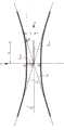
图2是本发明实施例中提供的圆锥曲面的双曲线示意图;Fig. 2 is a hyperbolic schematic diagram of a conic surface provided in an embodiment of the present invention;
图3是本发明实施例中提供的柱状透镜组装置的光学路径示意图;Fig. 3 is a schematic diagram of the optical path of the lenticular lens group device provided in the embodiment of the present invention;
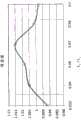
图4是本发明实施例中提供的柱状透镜组装置在不同[高度/宽度]比的光强度中心增益值;Fig. 4 is the light intensity center gain value of the lenticular lens group device provided in the embodiment of the present invention at different [height/width] ratios;
图5是本发明实施例中提供的柱状透镜组装置在柱状透镜层、第二折射率层的不同厚度比的光强度中心增益值;Fig. 5 is the light intensity center gain value of the lenticular lens group device provided in the embodiment of the present invention at different thickness ratios of the lenticular lens layer and the second refractive index layer;
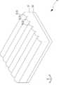
图6A是本发明实施例中提供的柱状透镜组装置的二维结构示意图;Fig. 6A is a two-dimensional structural schematic diagram of a lenticular lens group device provided in an embodiment of the present invention;
图6B是本发明实施例中提供的柱状透镜组装置的三维结构示意图;Fig. 6B is a three-dimensional structural schematic diagram of a lenticular lens group device provided in an embodiment of the present invention;
图6C是本发明实施例中提供的柱状透镜组装置的另一三维结构示意图;Fig. 6C is another three-dimensional structural schematic diagram of the lenticular lens group device provided in the embodiment of the present invention;
图7是本发明另实施例中提供的柱状透镜组装置的示意图;Fig. 7 is a schematic diagram of a lenticular lens group device provided in another embodiment of the present invention;
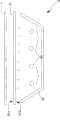
图8是本发明使用柱状透镜组装置的侧光式背光模块;FIG. 8 is a side-light backlight module using a lenticular lens group device according to the present invention;
图9是本发明使用柱状透镜组装置的直下式背光模块。FIG. 9 is a direct-lit backlight module using a lenticular lens group device according to the present invention.
附图中,各标号所代表的组件列表如下:In the accompanying drawings, the components represented by each label are listed as follows:
1、2、3、4、5:柱状透镜数组之装置,1, 2, 3, 4, 5: The device of the cylindrical lens array,
11、21、31、41、51:柱状透镜层,11, 21, 31, 41, 51: lenticular lens layer,
1131、2131、3131、4131:柱状透镜,1131, 2131, 3131, 4131: lenticular lens,
1132:曲面结构, 81B:入光面,1132: Curved surface structure, 81B: Light incident surface,
1132A:波峰, 82:光源,1132A: crest, 82: light source,
1132B:波谷, t1:第一厚度,1132B: valley, t1 : first thickness,
114:谷面, t2:第二厚度,114: valley surface, t2 : second thickness,
12、52:第二折射率层, R:曲率半径,12, 52: second refractive index layer, R: radius of curvature,
4131A:组合面, P:宽度,4131A: combined surface, P: width,
53:第三折射率层, H:高度,53: third refractive index layer, H: height,
7:侧光式背光模块, L1、L2:渐近线,7: Edge-lit backlight module, L1 , L2 : Asymptote,
71:导光板, L3:切割线,71: light guide plate, L3 : cutting line,
71A、81A:出光面, So:原点71A, 81A: light-emitting surface, So : origin
71C:底面, S1:顶点,71C: bottom surface,S1 : apex,
72:光源, S2:交点,72: light source, S2 : intersection point,
73:灯罩, T1:交界面,73: Shade, T1 : Interface,
74:扩散膜, θ1:折射角,74: Diffusion film, θ1 : Refraction angle,
75、85:反射片, θ2:入射角,75, 85: reflector, θ2 : incident angle,
8:直下式背光模块, θ1c:第一临界角,8: direct type backlight module, θ1c : first critical angle,
81:扩散板, θ2c:第二临界角,81: diffuser plate, θ2c : second critical angle,
θs:角度。θs: angle.
具体实施方式Detailed ways
为使本发明的目的、技术方案和优点更加清楚,下面将结合附图对本发明实施方式作进一步地详细描述。In order to make the object, technical solution and advantages of the present invention clearer, the implementation manner of the present invention will be further described in detail below in conjunction with the accompanying drawings.
实施例1Example 1
请参阅图1,图1所示是本发明所述柱状透镜组装置的示意图。如图1所示,一柱状透镜组装置1,由一柱状透镜层11及一第二折射率层12所构成,该柱状透镜层11与该第二折射率层12的相连接处为交界面T1。该柱状透镜层11包括有一谷面114及多个柱状透镜1131,多个柱状透镜1131横向排列且凸出于该谷面114上。该柱状透镜层11具有的一第一折射率,该第一折射率为n1;该交界面T1相距该谷面114具有一第一厚度t1。该柱状透镜1131更包括有相距一高度H的一波峰1132A及一波谷1132B,该波谷1132B位于该谷面114上,且该波峰1132A与该波谷1132B间具有一曲面结构1132;该曲面结构1132具有一曲率半径R,且相邻两波峰1132A之间相距有一宽度P。该第二折射率层12的第二折射率为n2,且具有一第二厚度t2,该第二厚度t2系自该交界面T1相距该第二折射率层12之底部的距离。如图1所示,光线从该柱状透镜组装置1的下方入光由上方出光,因此,光线在该柱状透镜组装置1内部,光线依序经过第二折射率层12、柱状透镜层11、曲面结构1132之后出光;故,该第二折射率层12位于该柱状透镜层11的入光面侧,该曲面结构1132位于柱状透镜层11的出光面的一侧。此外,该曲面结构1132为一双曲线的轮廓,且该曲面结构1132的圆锥常数为K,并且满足双曲线的公式:Please refer to FIG. 1 . FIG. 1 is a schematic diagram of the lenticular lens group device of the present invention. As shown in Figure 1, a lenticular
在传统圆锥曲面的定义上,一双曲线的曲线函数可由两相交的渐近线、贯轴以及共轭轴所决定;请参阅图2,图2所示是圆锥曲面的双曲线示意图。如图2所示,两双曲线分别位于两渐近线L1、L2的上方与下方。以两渐近线L1、L2的交点为坐标轴的原点So,该双曲线的顶点S1会与y轴相交,且该顶点S1至原点So的距离即为半贯轴Atran,该半贯轴Atran的距离为a。该顶点S1在水平方向上定义了一切割线L3,该切割线L3与该渐近线L1相交于一交点S2,该交点S2距离y轴的距离即为半共轭轴Aconj,该半共轭轴Aconj的距离为b。进一步地,依据圆锥曲面的基本定义,该双曲线的偏心率e及圆锥常数K分别为:In the definition of a traditional conic surface, the curve function of a hyperbola can be determined by two intersecting asymptotes, a transverse axis, and a conjugate axis; please refer to Figure 2, which is a schematic diagram of a hyperbola of a conic surface. As shown in FIG. 2 , the two hyperbolas are respectively located above and below the two asymptotes L1 and L2 . Taking the intersection point of two asymptotes L1 and L2 as the origin So of the coordinate axis, the vertex S1 of the hyperbola will intersect the y-axis, and the distance from the vertex S1 to the origin So is the semi-transverse axis Atran , the distance of the semi-transverse axis Atran is a. The vertex S1 defines a cutting line L3 in the horizontal direction, and the cutting line L3 and the asymptote line L1 intersect at an intersection point S2 , and the distance between the intersection point S2 and the y-axis is the semi-conjugate axis Aconj , the semi-conjugate axis Aconj is at a distance b. Further, according to the basic definition of a conic surface, the eccentricity e and the conic constant K of the hyperbola are respectively:
因此,只要确定该圆锥常数K、半贯轴Atran距离a与半共轭轴Aconj距离b,即可确定该双曲线函数。Therefore, as long as the conic constant K, the distance a of the semi-transverse axis Atran and the distance b of the semi-conjugate axis Aconj are determined, the hyperbolic function can be determined.
进一步地,将图2双曲线函数对应至图1的曲面结构1132,本实施例具有双曲线函数的曲面结构1132,只要通过宽度P、高度H、圆锥常数K,即可定义并确认该曲面结构1132的轮廓。另外,因为该曲面结构1132的轮廓为变曲率的弧线,因此该曲率半径R为波峰处1132A的曲率半径。另外,一般来说,双曲线函数的圆锥常数K的范围为:K<-1.0;而在本实施例中,该圆锥常数K的较佳范围为:K=-2.1~-1.5。Further, the hyperbolic function in Fig. 2 corresponds to the
接下来,在柱状透镜层11与第二折射率层12,为了避免由下往上射入的光线在交界面T1产生全反射现象,该柱状透镜层11的第一折射率n1大于该第二折射率层12的第二折射率n2,即n1>n2。依据折射定律(Snell’s Law):Next, in the
n1*sin(θ1)=n2*sin(θ2)n1 *sin(θ1 )=n2 *sin(θ2 )
可得到:θ2>θ1;也就是说,图1所述实施例中的光线自该柱状透镜层11经过该交界面T1之后射入至该第二折射率层12,其折射后的光线会向法线靠近,达到聚光的效果;如此,在该第二折射率层12内部具有较大入射角θ2的光线,其在经过该交界面T1之后,会被修正成为较”垂直”的状态;亦即:折射角θ1小于入射角θ2。因此,具有两种不同折射率的柱状透镜组装置1可用以提高光强度中心增益值。It can be obtained: θ2 >θ1 ; that is to say, the light in the embodiment shown in FIG. 1 enters the second
进一步地,为了达到让光线尽量垂直往上射出的目的,在光学路径的设计上应该要将偏离法线太大的光线重新导回该柱状透镜组装置1内部,藉以回收再利用其光能量。请参阅图3,图3所示是本发明所述柱状透镜组装置的光学路径示意图。如图3所示,在该曲面结构1132处,因为该柱状透镜1131的第一折射率为n1,该柱状透镜1131外侧的空气的折射率为1.0,且n1>1.0。由折射定律推导可知,在光线离开该曲面结构1132前,可由该柱状透镜层11定义一第一临界角θ1c,该第一临界角θ1c系光线与其法线方向(该法线方向与该谷面相垂直)的夹角,且Furthermore, in order to achieve the goal of letting the light go out as vertically as possible, in the design of the optical path, the light that deviates too much from the normal should be redirected back to the interior of the lenticular
如果光线射出该曲面结构1132前的角度大于该第一临界角θ1c,则光线会被全反射回该柱状透镜组装置1内部,在此,被全反射的光线为第一光学路径;如果光线射出该曲面结构1132前的角度小于该第一临界角θ1c,则光线即可射出且离开该曲面结构1132。基于充份利用光能量的考虑,如果让大于第一临界角θ1c的光线(即太倾斜的光线)射出该曲面结构1132,则对于提高光强度中心增益值是没有任何帮助的。故,为了修正偏离法线太大的光线,而利用此一第一临界角θ1c的物理特性来将大于第一临界角θ1c的光线(即太倾斜的光线)重新导回该柱状透镜组装置1内部。If the angle before the light exits the
如图3所示,本实施例的曲面结构1132的宽度为P以及高度为H,为了要使较大的入射角的光线被反射回该柱状透镜组装置1的内部,该角度θs必需要大于第一临界角θ1c,才能允许过于倾斜的光线产生全反射;亦即As shown in Figure 3, the width of the
当光线被导回至该柱状透镜组装置1内部后,会往下行进至该交界面T1之处。因为该柱状透镜层11的第一折射率为n1,该第二折射率层12的第二折射率为n2,且n1>n2,由折射定律可知,光线由大折射率的介质至小折射率的介质时,以产生临界角。依据折射定律可知,交界面T1之处,该第二折射率层12定义有一第二临界角θ2c,该第二临界角θ2c是光线与其该法线方向的夹角,且该第二临界角θ2c为第一折射率n1与第二折射率n2的函数,亦即After the light is guided back to the interior of the lenticular lens set
若光线向下至该交界面T1之前的角度大于该第二临界角θ2c,则光线会被全反射;若光线向下至该交界面T1前的角度小于该第二临界角θ2c,则光线即可往下前进而离开该交界面T1,形成一第二光学路径,该第二光学路径即可被重新回收利用。基于充份利用光能量的考虑,应该要让光线往下射出该交界面T1,而重新被回收利用。因此,与前述相同的原理,可得If the angle before the ray goes down to the interface T1 is greater than the second critical angle θ2c , the ray will be totally reflected; if the angle before the ray goes down to the interface T1 is smaller than the second critical angle θ2c , then The light can go down and leave the interface T1 to form a second optical path, and the second optical path can be recycled. Based on the consideration of making full use of the light energy, the light should be allowed to exit the interface T1 downwards and be recycled again. Therefore, with the same principle as above, we can get
综上公式(1)与(2),可得Combining the above formulas (1) and (2), we can get
由此,本发明的柱状透镜组装置1使光强度中心视角处的光线(即入射角较小的光线)偏向法线而射出该柱状透镜1131的曲面结构1132,并让倾斜度较大的光线(即入射角较大的光线)反射回该柱状透镜组装置1内部而重新回收利用,因此可进一步地提高光强度中心增益值。Thus, the lenticular
除了筛选过滤光线的倾斜角度之外,在此更通过Fresnelequation来计算本发明所述柱状透镜组装置1的总透光率;依据Fresnel equation公式:In addition to screening the angle of inclination of the filtered light, the total light transmittance of the lenticular
其中,T为透光率,R为反射率,nA、nB分别为两互相接触之介质的折射率。若该柱状透镜层11为聚碳酸酯(Polycarbonate,PC),该第二折射率层12为聚甲基丙烯酸甲酯(Polymethylmethacrylate,PMMA),PC的折射率为1.586,PMMA的折射率为1.49,空气的折射率为1.0,则本发明所述柱状透镜组装置1的总透光率为:Among them, T is the light transmittance, R is the reflectance, nA and nB are the refractive indices of the two media in contact with each other. If the
其与公知的传统增亮膜相较,可发现本发明具有两种不同折射率的结构可使总透光率由0.90再提升成为0.911。在制造业彼此杀价竞争的今日,只要产品的功效更好,即便仅有区区几个百分比的效益上的提升,便会造成双方巨大的获利差异。因此,总透光率由0.90再提升成为0.911,可说是技术改良上的一大突破。Compared with the known traditional brightness enhancement film, it can be found that the structure of the present invention with two different refractive indices can increase the total light transmittance from 0.90 to 0.911. In today's manufacturing industry that competes with each other, as long as the product has better efficacy, even if there is only a mere percentage increase in efficiency, it will cause a huge profit difference between the two parties. Therefore, the total light transmittance has been increased from 0.90 to 0.911, which can be said to be a major breakthrough in technological improvement.
另外,本发明所述柱状透镜组装置1更针对不同的圆锥常数K,以及不同的高度H与宽度P之比值,以实验的方式找出最佳光强度中心增益值;在此,该实验系以PC作为柱状透镜层11,PMMA作为第二折射率层12,圆锥常数K则区分为-1.5、-1.65、-1.75、-2及-2.1等五组。请参阅图4,图4所示是本发明所述柱状透镜组装置在不同[高度/宽度]比的光强度中心增益值。其各组实验的结果如下:In addition, the lenticular
(A)K=-1.5时:(A) When K=-1.5:
最佳的增益值系位于H/P=0.50之处,且增益值可达1.037;亦即,相较于公知的传统增亮膜,本组实验可再提高3.7%的增益值;The best gain value is located at H/P=0.50, and the gain value can reach 1.037; that is, compared with the known traditional brightness enhancement film, this group of experiments can increase the gain value by 3.7%;
(B)K=-1.65时:(B) When K=-1.65:
最佳的增益值系位于H/P=0.50之处,且增益值可达1.027;亦即,相较于公知的传统增亮膜,本组实验可再提高2.7%的增益值;The best gain value is located at H/P=0.50, and the gain value can reach 1.027; that is, compared with the known traditional brightness enhancement film, the gain value of this group of experiments can be increased by 2.7%;
(C)K=-1.75时:(C) When K=-1.75:
最佳的增益值系位于H/P=0.45之处,且增益值可达1.015;亦即,相较于公知的传统增亮膜,本组实验可再提高1.5%的增益值;The best gain value is located at H/P=0.45, and the gain value can reach 1.015; that is, compared with the known traditional brightness enhancement film, this group of experiments can increase the gain value by 1.5%;
(D)K=-2.0时:(D) When K=-2.0:
最佳的增益值系位于H/P=0.498之处,且增益值可达1.044;亦即,相较于公知的传统增亮膜,本组实验可再提高4.4%的增益值;The best gain value is located at H/P=0.498, and the gain value can reach 1.044; that is, compared with the known traditional brightness enhancement film, this group of experiments can increase the gain value by 4.4%;
(E)K=-2.1时:(E) When K=-2.1:
最佳的增益值系位于H/P=0.47之处,且增益值可达1.029;亦即,相较于公知的传统增亮膜,本组实验可再提高2.9%的增益值;The best gain value is located at H/P=0.47, and the gain value can reach 1.029; that is, compared with the known traditional brightness enhancement film, this group of experiments can increase the gain value by 2.9%;
由上述的结果可知,在上述五组圆锥常数K的实验中,当H/P=0.42~0.498时,发现本发明所述柱状透镜组装置1,其透过两个不同介质的结构,再加上双曲线轮廓的曲面结构1132,即可使一般市售的增亮膜再增加至最大4.4%的光强度,可以说是本技术领域上的一大突破。From the above results, it can be seen that in the experiments of the above five sets of conic constants K, when H/P=0.42~0.498, it was found that the lenticular
接下来,本发明更进一步针对该柱状透镜层11的第一厚度t1及第二折射率层12的第二厚度t2的比值作实验,藉以求得最佳的厚度关系。请参阅图5,图5所示是本发明所述柱状透镜组装置在柱状透镜层、第二折射率层之不同厚度比的光强度中心增益值。如图5所示,当t2/t1的比值位于0.035~0.084的范围时,其增益值均大于1.0;其中,当该t2/t1的比值为0.07时,其增益值最大可达1.015。也就是说,当t2/t1=0.035~0.084时,本发明的柱状透镜组装置1的光强度最大会比公知增亮膜的光强度高出1.5%。Next, the present invention further conducts experiments on the ratio of the first thickness t1 of the lenticular lens layer11 to the second thickness t2 of the second refractive index layer12 , so as to obtain an optimal thickness relationship. Please refer to FIG. 5 . FIG. 5 shows the center gain values of light intensity of the lenticular lens group device according to the present invention at different thickness ratios between the lenticular lens layer and the second refractive index layer. As shown in Figure 5, when the ratio of t2 /t1 is in the range of 0.035 to 0.084, the gain value is greater than 1.0; among them, when the ratio of t2 /t1 is 0.07, the maximum gain value can reach 1.015. That is to say, when t2 /t1 =0.035˜0.084, the light intensity of the
如上所述的柱状透镜组装置,本领域具有通常知识者可将其设计成为二维(2-Dimension)或三维(3-Dimension)的结构。请参阅图6A-图6C,图6A所示为本发明柱状透镜组装置的二维结构示意图,图6B所示为本发明柱状透镜组装置的三维结构示意图,图6C所示为本发明柱状透镜组装置的另一三维结构示意图。如图6A所示,该柱状透镜组装置2是由一柱状透镜层21及一第二折射率层22所组成,该柱状透镜层21的出光面侧排列有多个柱状透镜2131;该柱状透镜2131为双曲线轮廓的柱状体,因此为二维的结构。进一步地,如图6B所示,该柱状透镜组装置3是由一柱状透镜层31及一第二折射率层32所组成,该柱状透镜层31的出光面侧排列有多个柱状透镜3131;该柱状透镜3131系呈现双曲线的半圆球轮廓,从x-z平面或y-z平面观之,该柱状透镜3131均为双曲线的轮廓,因此为三维的结构。三维的柱状透镜组装置3与二维的柱状透镜组装置2相较,产生更均匀的光学效果,避免产生明暗相间的”暗带现象”。还有,如图6C所示,该柱状透镜组装置4是由一柱状透镜层41及一第二折射率层42所组成,该柱状透镜层41的出光面侧排列有多个柱状透镜4131;每一柱状透镜4131的轮廓系由四个组合面4131A所构成;从x-z平面或y-z平面观之,该柱状透镜4131为双曲线的轮廓。As for the lenticular lens group device described above, those skilled in the art can design it into a 2-Dimension or 3-Dimension structure. Please refer to Fig. 6A-Fig. 6C, Fig. 6A shows the two-dimensional structural diagram of the lenticular lens group device of the present invention, Fig. 6B shows the three-dimensional structural schematic diagram of the lenticular lens group device of the present invention, and Fig. 6C shows the lenticular lens of the present invention Another three-dimensional schematic diagram of the group device. As shown in FIG. 6A, the lenticular
此外,本发明的柱状透镜组装置更包括有三种不同的介质。请参阅图7,本发明另一实施例所述柱状透镜组装置的示意图。如图7所示,该柱状透镜组装置5包括有折射率分别为n1、n2、n3的柱状透镜层51、第二折射率层52及第三折射率层53依序排列且n1>n2>n3。也就是说,越靠近该柱状透镜组装置5的出光面侧,其折射率越大;如此,其所达成的功效也是让光线由下往上射出时,通过折射率的差异而使光线的行进路径向法线靠近,产生光线聚集的效果。相同地,在此以Fresnel equation来印证本实施例的总透光率,其中,该柱状透镜层51、第二折射率层52、第三折射率层53分别为PC、MS塑料、PMMA,且n1=1.586、n2=1.56、n3=1.49:In addition, the lenticular lens assembly device of the present invention further includes three different media. Please refer to FIG. 7 , which is a schematic diagram of a lenticular lens group device according to another embodiment of the present invention. As shown in FIG. 7 , the lenticular lens group device 5 includes a
因此,本实施例的总透光率亦是0.911,与前述实施例的功效大致相同。Therefore, the total light transmittance of this embodiment is also 0.911, which is roughly the same as that of the previous embodiment.
当然,上述所有实施例中,其柱状透镜层、第二折射率层或第三折射率层还可搭配使用聚乙烯对苯二甲酸酯(PolyethyleneTerephthalate,PET)、三醋酸纤维素(Tri-acetyl Cellulose,T AC)、甲基丙烯酸甲酯-苯乙烯共聚物(Methylmethacrylate styrene)、聚苯乙烯(Polystyrene,PS)或环烯共聚物(Cyclic Olefin Copolymer,COC)等不同的材质,来增加制造之多样性;只要符合出光面侧的折射率大于入光面侧的折射率,均可达前述聚光的功效。Of course, in all the above-mentioned embodiments, the lenticular lens layer, the second refractive index layer or the third refractive index layer can also be used together with polyethylene terephthalate (PolyethyleneTerephthalate, PET), tri-acetyl cellulose (Tri-acetyl Cellulose, T AC), methylmethacrylate-styrene copolymer (Methylmethacrylate styrene), polystyrene (Polystyrene, PS) or cycloolefin copolymer (Cyclic Olefin Copolymer, COC) and other different materials to increase the manufacturing time Diversity; as long as the refractive index of the light-emitting surface side is greater than that of the light-incoming surface side, the aforementioned light-concentrating effect can be achieved.
如上所述的柱状透镜组装置,可将其应用在侧光式背光模块或直下式背光模块。请参阅图8,图8所示为本发明使用柱状透镜组装置的侧光式背光模块。如图8所示,一侧光式背光模块7,其包括有一导光板71、两光源72、两灯罩73、一扩散膜74、一反射片75及一前述的柱状透镜组装置1。其中,该些光源72用以发射入射光。该导光板71的出光面71A与底面71C分别位于该导光板71相对应的两面。该光源72是设置于该导光板71的左侧边,利用该灯罩73反射其射出的光线,即可将光线投射至该导光板71内部;亦即,该导光板71传导入射光,用以形成一光学路径,而使光线均匀出射。该柱状透镜组装置1位于该导光板71的出光面71A外侧。该扩散膜74位于该导光板71与该柱状透镜组装置1之间,该反射片75位于该导光板71的底面71C外侧。在此,该光源72为冷阴极荧光灯管(Cold CathodeFluorescent Lamp,CCFL)、发光二极管(Light Emitting Diode,LED)或是产生光能量之光源。如此,通过本发明的柱状透镜组装置1,运用该第一临界角θ1c及该第二临界角θ2c修正其光学路径,而产生全反射至该反射片75,以形成该第二光学路径。因此,该侧光式背光模块7可用以降低光线的传输损耗,并提高光强度中心增益值。The above-mentioned lenticular lens group device can be applied to an edge-lit backlight module or a direct-lit backlight module. Please refer to FIG. 8 . FIG. 8 shows an edge-lit backlight module using a lenticular lens group device according to the present invention. As shown in FIG. 8 , the side-lit backlight module 7 includes a
请参阅图9所示为本发明使用柱状透镜组装置的直下式背光模块。如图9所示,一直下式背光模块8,其包括有一扩散板81、一光源82、一反射片85及一前述的柱状透镜组装置1。其中,该些光源82用以发射入射光。该扩散板81用以传输该入射光,藉以形成光学路径。该扩散板81的出光面81A与入光面81B分别位于该扩散板81相对应的两面。该反射片85设置于该扩散板81的入光面81B外侧。该光源82位于该扩散板81与该反射片85之间,用以将光线投射至该扩散板81内部。该柱状透镜组装置1位于该扩散板81的出光面81A侧。在此,该光源82可为多个CCFL或多个LED排列而成的平面光源。如此,通过本发明的柱状透镜组装置1可利用该第一临界角θ1c及该第二临界角θ2c修正其光学路径,而产生全反射至该反射片85,以形成该第二光学路径。因此,该直下式背光模块8即可用以降低光线的传输损耗,并提高光强度中心增益值。Please refer to FIG. 9 which shows the direct type backlight module using the lenticular lens group device of the present invention. As shown in FIG. 9 , the direct-type backlight module 8 includes a
综上所述,本发明的柱状透镜组装置及其使用的侧光式背光模块与直下式背光模块,通过两层或三层不同折射率介质组合成的柱状透镜组装置来加强聚光的效果,并通过双曲线轮廓的曲面结构而筛选射出的光线,使入射角过大(较偏离法线)的光线重新回到柱状透镜组装置或背光模块内部,回收再利用的效果。因此,降低损耗,并且提高光强度中心增益值。To sum up, the lenticular lens group device of the present invention and the side-lit backlight module and the direct-type backlight module used in the present invention enhance the effect of concentrating light through a lenticular lens group device composed of two or three layers of media with different refractive indices. , and the emitted light is screened through the curved surface structure of the hyperbolic outline, so that the light with an excessively large incident angle (deviating from the normal) returns to the interior of the lenticular lens group device or the backlight module, and the effect of recycling is achieved. Therefore, the loss is reduced, and the light intensity center gain value is increased.
以上所述仅为本发明的较佳实施例,并不用以限制本发明,凡在本发明的精神和原则之内,所作的任何修改、等同替换、改进等,均应包含在本发明的保护范围之内。The above descriptions are only preferred embodiments of the present invention, and are not intended to limit the present invention. Any modifications, equivalent replacements, improvements, etc. made within the spirit and principles of the present invention shall be included in the protection of the present invention. within range.
Claims (9)
Translated fromChinese


Priority Applications (1)
| Application Number | Priority Date | Filing Date | Title |
|---|---|---|---|
| CN 201010234299CN102338345B (en) | 2010-07-20 | 2010-07-20 | Lenticular lens group device and backlight module used therefor |
Applications Claiming Priority (1)
| Application Number | Priority Date | Filing Date | Title |
|---|---|---|---|
| CN 201010234299CN102338345B (en) | 2010-07-20 | 2010-07-20 | Lenticular lens group device and backlight module used therefor |
Publications (2)
| Publication Number | Publication Date |
|---|---|
| CN102338345A CN102338345A (en) | 2012-02-01 |
| CN102338345Btrue CN102338345B (en) | 2013-10-16 |
Family
ID=45514218
Family Applications (1)
| Application Number | Title | Priority Date | Filing Date |
|---|---|---|---|
| CN 201010234299ActiveCN102338345B (en) | 2010-07-20 | 2010-07-20 | Lenticular lens group device and backlight module used therefor |
Country Status (1)
| Country | Link |
|---|---|
| CN (1) | CN102338345B (en) |
Families Citing this family (6)
| Publication number | Priority date | Publication date | Assignee | Title |
|---|---|---|---|---|
| KR101991839B1 (en)* | 2013-01-15 | 2019-06-24 | 삼성디스플레이 주식회사 | Display device having cover window |
| CN104100852A (en)* | 2013-04-09 | 2014-10-15 | 中蓝光电科技(上海)有限公司 | LED illuminating device with micro-structure optical film |
| CN103712155B (en)* | 2013-12-24 | 2017-11-03 | 京东方科技集团股份有限公司 | Lampshade, backlight module and display device |
| KR101993150B1 (en)* | 2014-03-17 | 2019-06-26 | 동우 화인켐 주식회사 | Light guiding plate and backlight unit comprising the same |
| KR102592717B1 (en)* | 2019-04-30 | 2023-10-23 | 삼성디스플레이 주식회사 | Optical film and display device having the same |
| CN113703186A (en)* | 2020-05-22 | 2021-11-26 | 北京芯海视界三维科技有限公司 | Lens, grating, display panel and display |
Citations (4)
| Publication number | Priority date | Publication date | Assignee | Title |
|---|---|---|---|---|
| CN1947035A (en)* | 2004-09-30 | 2007-04-11 | 索尼株式会社 | Optical sheet, backlight, and liquid crystal display device |
| CN101055324A (en)* | 2006-04-14 | 2007-10-17 | 索尼株式会社 | Optical sheet, backlight device and liquid crystal display device |
| CN101095076A (en)* | 2004-12-30 | 2007-12-26 | 3M创新有限公司 | Brightness enhancement article |
| US7440153B2 (en)* | 2005-06-11 | 2008-10-21 | Samsung Electro-Mechanics Co., Ltd | Backlight unit for flat panel display and flat panel display apparatus having the same |
- 2010
- 2010-07-20CNCN 201010234299patent/CN102338345B/enactiveActive
Patent Citations (4)
| Publication number | Priority date | Publication date | Assignee | Title |
|---|---|---|---|---|
| CN1947035A (en)* | 2004-09-30 | 2007-04-11 | 索尼株式会社 | Optical sheet, backlight, and liquid crystal display device |
| CN101095076A (en)* | 2004-12-30 | 2007-12-26 | 3M创新有限公司 | Brightness enhancement article |
| US7440153B2 (en)* | 2005-06-11 | 2008-10-21 | Samsung Electro-Mechanics Co., Ltd | Backlight unit for flat panel display and flat panel display apparatus having the same |
| CN101055324A (en)* | 2006-04-14 | 2007-10-17 | 索尼株式会社 | Optical sheet, backlight device and liquid crystal display device |
Also Published As
| Publication number | Publication date |
|---|---|
| CN102338345A (en) | 2012-02-01 |
Similar Documents
| Publication | Publication Date | Title |
|---|---|---|
| CN101487948B (en) | Optical sheet, and backlight unit and display using the same | |
| CN101487945B (en) | Optical sheet and display device having the same | |
| CN102338345B (en) | Lenticular lens group device and backlight module used therefor | |
| CN104932140B (en) | Backlight module | |
| JP2007188031A (en) | Diffuser plate for higher light diffusion and luminance | |
| CN107003558A (en) | Composite optical sheet, the Liquid crystal disply device and its preparation method using it | |
| US20130294108A1 (en) | Optical film and backlight module using the same | |
| TWI439735B (en) | Lenticular array device and backlight module | |
| CN103502849A (en) | Microlens array sheet and backlight unit including same | |
| JP5493312B2 (en) | Surface light emitting device and image display device | |
| CN108167683B (en) | Composite diffusion plate and ultrathin direct type backlight module | |
| CN101956950A (en) | Optical thin plate and manufacturing method thereof and backlight module | |
| KR102036797B1 (en) | Unified Optical Sheet Module and Backlight Unit Having the Same | |
| JP6023057B2 (en) | Optical sheet, optical unit, and illumination device using the same | |
| JP2010251053A (en) | Light uniform element, backlight unit and display device using the same | |
| CN101285902B (en) | Diffusion plate group | |
| JP7745912B2 (en) | Light control film, backlight unit, and display device | |
| CN102162868B (en) | Optical sheet and backlight module with optical sheet | |
| US20110044072A1 (en) | Backlight module and light guide unit | |
| JP5293177B2 (en) | Optical sheet, surface light source device and display device | |
| CN216561322U (en) | Backlight module and display device | |
| CN114002881B (en) | Backlight module | |
| JP4815879B2 (en) | Light transmissive film, backlight device, and liquid crystal display device | |
| JP5182128B2 (en) | Optical sheet, surface light source device and display device | |
| CN102455458B (en) | Light guide device and backlight module |
Legal Events
| Date | Code | Title | Description |
|---|---|---|---|
| C06 | Publication | ||
| PB01 | Publication | ||
| C10 | Entry into substantive examination | ||
| SE01 | Entry into force of request for substantive examination | ||
| C14 | Grant of patent or utility model | ||
| GR01 | Patent grant |