CN102334050A - Internally patterned multilayer optical film with multiple birefringent layers - Google Patents
Internally patterned multilayer optical film with multiple birefringent layersDownload PDFInfo
- Publication number
- CN102334050A CN102334050ACN2009801573243ACN200980157324ACN102334050ACN 102334050 ACN102334050 ACN 102334050ACN 2009801573243 ACN2009801573243 ACN 2009801573243ACN 200980157324 ACN200980157324 ACN 200980157324ACN 102334050 ACN102334050 ACN 102334050A
- Authority
- CN
- China
- Prior art keywords
- film
- microbedding
- group
- district
- layers
- Prior art date
- Legal status (The legal status is an assumption and is not a legal conclusion. Google has not performed a legal analysis and makes no representation as to the accuracy of the status listed.)
- Granted
Links
Images


Classifications
- G—PHYSICS
- G02—OPTICS
- G02B—OPTICAL ELEMENTS, SYSTEMS OR APPARATUS
- G02B5/00—Optical elements other than lenses
- G02B5/30—Polarising elements
- G02B5/3025—Polarisers, i.e. arrangements capable of producing a definite output polarisation state from an unpolarised input state
- G02B5/3033—Polarisers, i.e. arrangements capable of producing a definite output polarisation state from an unpolarised input state in the form of a thin sheet or foil, e.g. Polaroid
- G02B5/3041—Polarisers, i.e. arrangements capable of producing a definite output polarisation state from an unpolarised input state in the form of a thin sheet or foil, e.g. Polaroid comprising multiple thin layers, e.g. multilayer stacks
- B—PERFORMING OPERATIONS; TRANSPORTING
- B42—BOOKBINDING; ALBUMS; FILES; SPECIAL PRINTED MATTER
- B42D—BOOKS; BOOK COVERS; LOOSE LEAVES; PRINTED MATTER CHARACTERISED BY IDENTIFICATION OR SECURITY FEATURES; PRINTED MATTER OF SPECIAL FORMAT OR STYLE NOT OTHERWISE PROVIDED FOR; DEVICES FOR USE THEREWITH AND NOT OTHERWISE PROVIDED FOR; MOVABLE-STRIP WRITING OR READING APPARATUS
- B42D25/00—Information-bearing cards or sheet-like structures characterised by identification or security features; Manufacture thereof
- B42D25/20—Information-bearing cards or sheet-like structures characterised by identification or security features; Manufacture thereof characterised by a particular use or purpose
- B42D25/23—Identity cards
- B—PERFORMING OPERATIONS; TRANSPORTING
- B42—BOOKBINDING; ALBUMS; FILES; SPECIAL PRINTED MATTER
- B42D—BOOKS; BOOK COVERS; LOOSE LEAVES; PRINTED MATTER CHARACTERISED BY IDENTIFICATION OR SECURITY FEATURES; PRINTED MATTER OF SPECIAL FORMAT OR STYLE NOT OTHERWISE PROVIDED FOR; DEVICES FOR USE THEREWITH AND NOT OTHERWISE PROVIDED FOR; MOVABLE-STRIP WRITING OR READING APPARATUS
- B42D25/00—Information-bearing cards or sheet-like structures characterised by identification or security features; Manufacture thereof
- B42D25/20—Information-bearing cards or sheet-like structures characterised by identification or security features; Manufacture thereof characterised by a particular use or purpose
- B42D25/24—Passports
- B—PERFORMING OPERATIONS; TRANSPORTING
- B42—BOOKBINDING; ALBUMS; FILES; SPECIAL PRINTED MATTER
- B42D—BOOKS; BOOK COVERS; LOOSE LEAVES; PRINTED MATTER CHARACTERISED BY IDENTIFICATION OR SECURITY FEATURES; PRINTED MATTER OF SPECIAL FORMAT OR STYLE NOT OTHERWISE PROVIDED FOR; DEVICES FOR USE THEREWITH AND NOT OTHERWISE PROVIDED FOR; MOVABLE-STRIP WRITING OR READING APPARATUS
- B42D25/00—Information-bearing cards or sheet-like structures characterised by identification or security features; Manufacture thereof
- B42D25/30—Identification or security features, e.g. for preventing forgery
- B42D25/36—Identification or security features, e.g. for preventing forgery comprising special materials
- B42D25/378—Special inks
- B42D25/391—Special inks absorbing or reflecting polarised light
- G—PHYSICS
- G02—OPTICS
- G02B—OPTICAL ELEMENTS, SYSTEMS OR APPARATUS
- G02B27/00—Optical systems or apparatus not provided for by any of the groups G02B1/00 - G02B26/00, G02B30/00
- G02B27/28—Optical systems or apparatus not provided for by any of the groups G02B1/00 - G02B26/00, G02B30/00 for polarising
- G—PHYSICS
- G02—OPTICS
- G02B—OPTICAL ELEMENTS, SYSTEMS OR APPARATUS
- G02B5/00—Optical elements other than lenses
- G02B5/08—Mirrors
- G02B5/0816—Multilayer mirrors, i.e. having two or more reflecting layers
- G—PHYSICS
- G02—OPTICS
- G02B—OPTICAL ELEMENTS, SYSTEMS OR APPARATUS
- G02B5/00—Optical elements other than lenses
- G02B5/08—Mirrors
- G02B5/0816—Multilayer mirrors, i.e. having two or more reflecting layers
- G02B5/0825—Multilayer mirrors, i.e. having two or more reflecting layers the reflecting layers comprising dielectric materials only
- G02B5/0841—Multilayer mirrors, i.e. having two or more reflecting layers the reflecting layers comprising dielectric materials only comprising organic materials, e.g. polymers
- G—PHYSICS
- G02—OPTICS
- G02B—OPTICAL ELEMENTS, SYSTEMS OR APPARATUS
- G02B5/00—Optical elements other than lenses
- G02B5/20—Filters
- G02B5/28—Interference filters
- G02B5/285—Interference filters comprising deposited thin solid films
- G—PHYSICS
- G02—OPTICS
- G02B—OPTICAL ELEMENTS, SYSTEMS OR APPARATUS
- G02B5/00—Optical elements other than lenses
- G02B5/20—Filters
- G02B5/28—Interference filters
- G02B5/285—Interference filters comprising deposited thin solid films
- G02B5/287—Interference filters comprising deposited thin solid films comprising at least one layer of organic material
- G—PHYSICS
- G02—OPTICS
- G02B—OPTICAL ELEMENTS, SYSTEMS OR APPARATUS
- G02B5/00—Optical elements other than lenses
- G02B5/30—Polarising elements
- G02B5/3025—Polarisers, i.e. arrangements capable of producing a definite output polarisation state from an unpolarised input state
- G02B5/3033—Polarisers, i.e. arrangements capable of producing a definite output polarisation state from an unpolarised input state in the form of a thin sheet or foil, e.g. Polaroid
- G02B5/3041—Polarisers, i.e. arrangements capable of producing a definite output polarisation state from an unpolarised input state in the form of a thin sheet or foil, e.g. Polaroid comprising multiple thin layers, e.g. multilayer stacks
- G02B5/305—Polarisers, i.e. arrangements capable of producing a definite output polarisation state from an unpolarised input state in the form of a thin sheet or foil, e.g. Polaroid comprising multiple thin layers, e.g. multilayer stacks including organic materials, e.g. polymeric layers
- G—PHYSICS
- G02—OPTICS
- G02B—OPTICAL ELEMENTS, SYSTEMS OR APPARATUS
- G02B5/00—Optical elements other than lenses
- G02B5/30—Polarising elements
- G02B5/3083—Birefringent or phase retarding elements
- G—PHYSICS
- G02—OPTICS
- G02F—OPTICAL DEVICES OR ARRANGEMENTS FOR THE CONTROL OF LIGHT BY MODIFICATION OF THE OPTICAL PROPERTIES OF THE MEDIA OF THE ELEMENTS INVOLVED THEREIN; NON-LINEAR OPTICS; FREQUENCY-CHANGING OF LIGHT; OPTICAL LOGIC ELEMENTS; OPTICAL ANALOGUE/DIGITAL CONVERTERS
- G02F1/00—Devices or arrangements for the control of the intensity, colour, phase, polarisation or direction of light arriving from an independent light source, e.g. switching, gating or modulating; Non-linear optics
- G02F1/01—Devices or arrangements for the control of the intensity, colour, phase, polarisation or direction of light arriving from an independent light source, e.g. switching, gating or modulating; Non-linear optics for the control of the intensity, phase, polarisation or colour
- G02F1/13—Devices or arrangements for the control of the intensity, colour, phase, polarisation or direction of light arriving from an independent light source, e.g. switching, gating or modulating; Non-linear optics for the control of the intensity, phase, polarisation or colour based on liquid crystals, e.g. single liquid crystal display cells
- G02F1/133—Constructional arrangements; Operation of liquid crystal cells; Circuit arrangements
- G02F1/1333—Constructional arrangements; Manufacturing methods
- G02F1/1335—Structural association of cells with optical devices, e.g. polarisers or reflectors
- G02F1/133528—Polarisers
- G02F1/133536—Reflective polarizers
- G—PHYSICS
- G02—OPTICS
- G02F—OPTICAL DEVICES OR ARRANGEMENTS FOR THE CONTROL OF LIGHT BY MODIFICATION OF THE OPTICAL PROPERTIES OF THE MEDIA OF THE ELEMENTS INVOLVED THEREIN; NON-LINEAR OPTICS; FREQUENCY-CHANGING OF LIGHT; OPTICAL LOGIC ELEMENTS; OPTICAL ANALOGUE/DIGITAL CONVERTERS
- G02F1/00—Devices or arrangements for the control of the intensity, colour, phase, polarisation or direction of light arriving from an independent light source, e.g. switching, gating or modulating; Non-linear optics
- G02F1/01—Devices or arrangements for the control of the intensity, colour, phase, polarisation or direction of light arriving from an independent light source, e.g. switching, gating or modulating; Non-linear optics for the control of the intensity, phase, polarisation or colour
- G02F1/13—Devices or arrangements for the control of the intensity, colour, phase, polarisation or direction of light arriving from an independent light source, e.g. switching, gating or modulating; Non-linear optics for the control of the intensity, phase, polarisation or colour based on liquid crystals, e.g. single liquid crystal display cells
- G02F1/133—Constructional arrangements; Operation of liquid crystal cells; Circuit arrangements
- G02F1/1333—Constructional arrangements; Manufacturing methods
- G02F1/1335—Structural association of cells with optical devices, e.g. polarisers or reflectors
- G02F1/13363—Birefringent elements, e.g. for optical compensation
- G—PHYSICS
- G02—OPTICS
- G02B—OPTICAL ELEMENTS, SYSTEMS OR APPARATUS
- G02B5/00—Optical elements other than lenses
- G02B5/30—Polarising elements
- G—PHYSICS
- G02—OPTICS
- G02F—OPTICAL DEVICES OR ARRANGEMENTS FOR THE CONTROL OF LIGHT BY MODIFICATION OF THE OPTICAL PROPERTIES OF THE MEDIA OF THE ELEMENTS INVOLVED THEREIN; NON-LINEAR OPTICS; FREQUENCY-CHANGING OF LIGHT; OPTICAL LOGIC ELEMENTS; OPTICAL ANALOGUE/DIGITAL CONVERTERS
- G02F1/00—Devices or arrangements for the control of the intensity, colour, phase, polarisation or direction of light arriving from an independent light source, e.g. switching, gating or modulating; Non-linear optics
- G02F1/01—Devices or arrangements for the control of the intensity, colour, phase, polarisation or direction of light arriving from an independent light source, e.g. switching, gating or modulating; Non-linear optics for the control of the intensity, phase, polarisation or colour
- G02F1/13—Devices or arrangements for the control of the intensity, colour, phase, polarisation or direction of light arriving from an independent light source, e.g. switching, gating or modulating; Non-linear optics for the control of the intensity, phase, polarisation or colour based on liquid crystals, e.g. single liquid crystal display cells
- G02F1/133—Constructional arrangements; Operation of liquid crystal cells; Circuit arrangements
- G02F1/1333—Constructional arrangements; Manufacturing methods
- G02F1/1335—Structural association of cells with optical devices, e.g. polarisers or reflectors
- G02F1/133509—Filters, e.g. light shielding masks
- G02F1/133514—Colour filters
- G02F1/133521—Interference filters
- Y—GENERAL TAGGING OF NEW TECHNOLOGICAL DEVELOPMENTS; GENERAL TAGGING OF CROSS-SECTIONAL TECHNOLOGIES SPANNING OVER SEVERAL SECTIONS OF THE IPC; TECHNICAL SUBJECTS COVERED BY FORMER USPC CROSS-REFERENCE ART COLLECTIONS [XRACs] AND DIGESTS
- Y10—TECHNICAL SUBJECTS COVERED BY FORMER USPC
- Y10T—TECHNICAL SUBJECTS COVERED BY FORMER US CLASSIFICATION
- Y10T428/00—Stock material or miscellaneous articles
- Y10T428/24—Structurally defined web or sheet [e.g., overall dimension, etc.]
- Y10T428/24942—Structurally defined web or sheet [e.g., overall dimension, etc.] including components having same physical characteristic in differing degree
Landscapes
- Physics & Mathematics (AREA)
- General Physics & Mathematics (AREA)
- Optics & Photonics (AREA)
- Nonlinear Science (AREA)
- Mathematical Physics (AREA)
- Crystallography & Structural Chemistry (AREA)
- Chemical & Material Sciences (AREA)
- Polarising Elements (AREA)
- Laminated Bodies (AREA)
- Credit Cards Or The Like (AREA)
- Optical Filters (AREA)
- Optical Elements Other Than Lenses (AREA)
- Liquid Crystal (AREA)
Abstract
Description
Translated fromChinese相关专利申请的交叉引用Cross references to related patent applications
本专利申请要求以下美国临时申请的优先权:No.61/139,736“Internally Patterned Multilayer Optical Films Using Spatially SelectiveBirefringence Reduction”(利用空间选择性双折射减小的内部图案化的多层光学膜),2008年12月22日提交;No.61/157,996“Multilayer OpticalFilms Having Side-by-Side Mirror/Polarizer Zones”(具有并列型反射镜/偏振器区的多层光学膜),2009年3月6日提交;和No.61/158,006“Multilayer Optical Films Suitable for Bi-Level Internal Patterning”(适用于双层内部图案化的多层光学膜),2009年3月6日提交,这些申请的公开内容以引用方式并入本文。This patent application claims priority from the following U.S. provisional application: No. 61/139,736 "Internally Patterned Multilayer Optical Films Using Spatially Selective Birefringence Reduction," 2008 Submitted on December 22; No.61/157,996 "Multilayer Optical Films Having Side-by-Side Mirror/Polarizer Zones" (multilayer optical film with side-by-side mirrors/polarizer zones), submitted on March 6, 2009; and No. 61/158,006 "Multilayer Optical Films Suitable for Bi-Level Internal Patterning," filed March 6, 2009, the disclosures of which are incorporated by reference into this article.
技术领域technical field
本发明整体涉及光学膜,尤其适用于这样的膜:该膜的反射特性大部分由从膜内设置(即膜的内部)的层间界面反射光的相长干涉和相消干涉所确定。本发明还涉及相关系统和方法。The present invention relates generally to optical films, and is particularly applicable to films whose reflective properties are largely determined by constructive and destructive interference of light reflected from interlayer interfaces disposed within the film (ie, interior of the film). The invention also relates to related systems and methods.
背景技术Background technique
已知多层光学膜,即这种膜包括多层具有不同折射率和合适厚度的不同层,以由于在层间界面处反射光的相长干涉和相消干涉而选择性地反射和透射光。在一些情况下,这种膜通过以下方式形成:将高折射率无机材料(例如二氧化钛)和低折射率无机材料(例如二氧化硅)的交替层真空沉积到玻璃基底或其它刚性基底上。Multilayer optical films are known, ie such films comprise a plurality of different layers with different refractive indices and suitable thicknesses to selectively reflect and transmit light due to constructive and destructive interference of reflected light at interfaces between the layers. In some cases, such films are formed by vacuum depositing alternating layers of high refractive index inorganic materials such as titanium dioxide and low refractive index inorganic materials such as silicon dioxide onto glass substrates or other rigid substrates.
在其它情况下,这种膜通过以下方式形成:以交替层布置方式通过模具共挤出不同的有机聚合物材料,冷却挤出物以形成浇铸料片,以及拉伸浇铸料片,以便使料片变薄到合适的最终厚度。在一些情况下,也可以通过使交替聚合物材料中的一者或两者成为双折射的方式来进行拉伸,即,其中给定材料对沿一个方向偏振的光具有某一折射率,而对沿不同方向偏振的光具有不同的折射率。这种双折射可以导致下述成品膜:该成品膜在相邻层间沿第一面内方向(有时称为x轴)具有大的折射率失配,并且在相邻层间沿第二面内方向(有时称为y轴)具有显著的折射率匹配,其中在成品膜上,沿第一方向偏振的垂直入射光为高度反射的光,并且沿第二方向偏振的垂直入射光为高度透射的光。参见(如)以下美国专利:3,610,729(Rogers)、4,446,305(Rogers等人)和5,486,949(Schrenk等人)。双折射也可以导致相邻层间沿面外方向(即沿垂直于膜的轴)的折射率差值,其显著不同于相邻层间沿一个或两个面内方向的折射率差值。此后一情况的实例为下述膜:该膜在相邻层间沿两个正交面内方向(x和y)具有基本上相同的大的折射率失配,使得任何偏振的垂直入射光均为高度反射的光,但其中相邻层沿面外方向(z)的折射率为基本上匹配的折射率,使得所谓“p偏振”光(在入射平面内偏振的光)的界面的反射率为基本上恒定的。参见(如)美国专利5,882,774(Jonza等人)。Jonza等人提出,除了别的以外,相邻微层之间的z轴折射率失配(简称为z折射率失配或Δnz)可被调控,以允许构造布鲁斯特角(p偏振光在界面处的反射率变为零的角度)非常大或不存在的多层叠堆。这又允许构造这样的多层反射镜和偏振器:其p偏振光的界面反射率随着入射角增加而缓慢减小,或与入射角无关,或随着入射角偏离垂直方向而增大。因此,可得到在宽的带宽上对s偏振光和p偏振光均具有高反射率的多层膜,其中s偏振光垂直于入射平面偏振,p偏振光对于反射镜以任何入射方向、对于偏振器以选定的方向偏振。In other cases, such films are formed by coextruding different organic polymer materials through a die in an alternating layer arrangement, cooling the extrudate to form a cast web, and stretching the cast web so that the The sheet is thinned to a suitable final thickness. In some cases, stretching can also be performed by making one or both of the alternating polymer materials birefringent, i.e., where a given material has a certain index of refraction for light polarized in one direction, and It has different refractive indices for light polarized in different directions. This birefringence can result in a finished film that has a large refractive index mismatch between adjacent layers along the first in-plane direction (sometimes called the x-axis), and a large refractive index mismatch between adjacent layers along the second plane. The inner direction (sometimes referred to as the y-axis) has significant refractive index matching where, on the finished film, light at normal incidence polarized in a first direction is highly reflective and light at normal incidence polarized in a second direction is highly transmissive of light. See, eg, the following US Patents: 3,610,729 (Rogers), 4,446,305 (Rogers et al.), and 5,486,949 (Schrenk et al.). Birefringence can also result in a refractive index difference between adjacent layers along an out-of-plane direction (ie, along an axis perpendicular to the film) that is significantly different from a refractive index difference between adjacent layers along one or both in-plane directions. An example of the latter case is a film that has substantially the same large refractive index mismatch between adjacent layers along the two orthogonal in-plane directions (x and y) such that normally incident light of any polarization is homogeneous. is highly reflective light, but where the refractive indices of adjacent layers along the out-of-plane direction (z) substantially match such that the reflectance of the interface for so-called "p-polarized" light (light polarized in the plane of incidence) is basically constant. See, eg, US Patent 5,882,774 (Jonza et al.). Jonza et al. propose that, among other things, the z-index mismatch between adjacent microlayers (abbreviated as z-index mismatch or Δnz) can be tuned to allow the construction of Brewster's angle (p-polarized light at the interface The angle at which the reflectivity becomes zero) is very large or non-existent in multilayer stacks. This in turn allows the construction of multilayer mirrors and polarizers whose interfacial reflectivity for p-polarized light decreases slowly with increasing angle of incidence, or is independent of angle of incidence, or increases with angle of incidence away from the normal direction. Thus, multilayer films can be obtained with high reflectivity over a wide bandwidth for both s-polarized light and p-polarized light, where s-polarized light is polarized perpendicular to the plane of incidence, and p-polarized light is incident on the mirror in any direction of incidence, for polarization The polarizer is polarized in a selected direction.
另外已知向多层光学膜赋予图案,以形成标记。参见(如)以下美国专利:6,045,894(Jonza等人)“Clear to Colored Security Film”(透明至彩色安全膜);6,531,230(Weber等人)“Color Shifting Film”(色移膜);和6,788,463(Merrill等人)“Post-Formable Multilayer OpticalFilms and Methods of Forming”(可后形成的多层光学膜以及形成方法)。将压力选择性地施加到膜,例如利用压印模具,以使选定区中的膜变薄,以产生所需图案。可以产生的厚度减少为大于5%或大于大约10%的选择性薄化在膜选定区中的整个厚度上均为有效的,使得膜内部的选定区中的光学薄层(“微层”)的叠堆相对于膜的相邻区也变薄,该微层是造成所观测的反射和透射特性的原因。由于穿过微层的光学路径长度差缩短,微层的这种薄化使与微层相关的任何反射谱带偏移为较短波长。对于观察者而言,反射谱带的偏移显示为压印区和非压印区之间的反射或透射颜色差值,以使得图案易于被察觉到。It is also known to impart patterns to multilayer optical films to form indicia. See (eg) the following U.S. Patents: 6,045,894 (Jonza et al.) "Clear to Colored Security Film"; 6,531,230 (Weber et al.) "Color Shifting Film"; and 6,788,463 (Merrill et al) "Post-Formable Multilayer Optical Films and Methods of Forming" (multilayer optical films that can be formed later and methods of formation). Pressure is selectively applied to the film, such as with an embossing die, to thin the film in selected regions to produce the desired pattern. The selective thinning that can produce a reduction in thickness of greater than 5% or greater than about 10% is effective throughout the thickness in selected regions of the film such that optically thin layers ("microlayers") in selected regions inside the film ”) is also thinned relative to the adjacent regions of the film, this microlayer is responsible for the observed reflective and transmissive properties. This thinning of the microlayers shifts any reflection bands associated with the microlayers to shorter wavelengths due to the shortened optical path length difference across the microlayers. To the observer, the shift in reflectance bands appears as a difference in reflective or transmitted color between embossed and non-embossed areas so that the pattern is easily perceived.
例如,‘463 Merrill等人的专利描述了压印色移安全膜,其中将包含418层内部微层(两组各具有209层微层)的多层聚合物膜压印在选定区中。在压印之前、以及在压印之后的非压印区中,微层具有产生下述反射谱带的折射率和厚度:反射谱带的短波长谱带边缘随入射角(视角)而偏移,即,从垂直入射下的720nm改变为45度视角下的640nm、改变为60度视角下的甚至更短波长(对应于垂直入射下的透明外观、45度下的青色、60度下的亮青色)。在这些非压印区中,膜的厚度为3.4密耳,即0.0034英寸。然后将膜在149℃下的辊和预热压印板之间进行压印,以将选定区中的膜薄化到约3.0密耳。压印区在垂直入射下显示为亮金色,这表明谱带边缘从720nm偏移为较短波长。在倾斜视角下,压印区中的观测颜色改变为青色或较深的蓝色。For example, the '463 Merrill et al. patent describes an embossed color shifting security film in which a multilayer polymer film comprising 418 inner microlayers (two sets of 209 microlayers each) is embossed in selected areas. Before embossing, and in non-embossed regions after embossing, the microlayer has a refractive index and thickness that produces a reflection band whose short-wavelength band edge shifts with the angle of incidence (viewing angle) , that is, changing from 720nm at normal incidence to 640nm at 45° to an even shorter wavelength at 60° (corresponding to transparent appearance at normal incidence, cyan at 45°, bright at 60° blue). In these non-embossed areas, the film thickness was 3.4 mils, or 0.0034 inches. The film was then embossed between a roll at 149°C and a preheated platen to thin the film to about 3.0 mils in selected areas. The imprinted region appears bright gold at normal incidence, which indicates a band edge shift from 720 nm to shorter wavelengths. At oblique viewing angles, the observed color in the embossed area changes to cyan or a darker blue.
发明内容Contents of the invention
除了别的以外,本文描述使多层光学膜内部图案化的方法,该方法不需要选择性地施加压力,并且不依赖于选择性地使膜薄化来而实现图案化。因此,在一些情况下,本文论述的内部图案化能够实现而无需对膜进行任何选择性施加压力和/或无需对膜进行任何显著薄化。相反,本发明所公开的方法中的至少一些通过在第二区中而非相邻的第一区中选择性地减少膜的内层中的至少一些的双折射来实现图案化。在其它情况下,内部图案化可以伴有厚度的显著变化,厚度变化取决于处理条件而为较厚或较薄的。Described herein, among other things, are methods of patterning the interior of multilayer optical films that do not require selective application of pressure and that do not rely on selectively thinning the film to achieve patterning. Thus, in some cases, the internal patterning discussed herein can be achieved without any selective application of pressure to the membrane and/or without any significant thinning of the membrane. In contrast, at least some of the methods disclosed herein achieve patterning by selectively reducing the birefringence of at least some of the inner layers of the film in the second region but not in the adjacent first region. In other cases, internal patterning can be accompanied by significant variations in thickness, being thicker or thinner depending on processing conditions.
选择性双折射减少可通过下述方法进行:将适当量的能量审慎地递送至第二区,以便将其中的内层中的至少一些选择性加热至下述温度,所述温度为足够高,以在减少或消除原有光学双折射的材料中产生松弛,而且为足够低,以保持膜内的层结构的物理完整性。双折射的减少可以为部分减少,或其可以为完全减少,在此情况下,使第一区中为双折射的内层变成第二区中的光学各向同性的层。在示例性实施例中,至少部分地通过将光或其它辐射能量选择性地递送至膜的第二区来实现选择性加热。光可以包括紫外光、可见光或红外波长的光或它们的组合。被递送的光中的至少一些被膜吸收,从而得到所需的加热,其中所吸收光的量取决于强度、持续时间和被递送的光的波长分布、以及膜的吸收特性。这种用于使多层光学膜内部图案化的技术与已知高强度光源和电子可寻址光束控制系统相容,从而允许仅通过适当地控制光束(无需专用硬件,例如图像专用压印板或光掩模)在膜中产生事实上任何所需的图案或图像。Selective birefringence reduction may be performed by judiciously delivering an appropriate amount of energy to the second zone to selectively heat at least some of the inner layers therein to a temperature high enough that The slack in the material reduces or eliminates the original optical birefringence, and is low enough to maintain the physical integrity of the layer structure within the film. The reduction in birefringence may be a partial reduction, or it may be a complete reduction, in which case an inner layer that is birefringent in the first zone becomes an optically isotropic layer in the second zone. In an exemplary embodiment, selective heating is achieved at least in part by selectively delivering light or other radiant energy to the second region of the film. The light may include ultraviolet, visible, or infrared wavelengths of light, or combinations thereof. At least some of the delivered light is absorbed by the membrane, resulting in the desired heating, wherein the amount of absorbed light depends on the intensity, duration and wavelength distribution of the delivered light, and the absorption properties of the membrane. This technique for patterning the interior of multilayer optical films is compatible with known high-intensity light sources and electronically addressable beam-steering systems, allowing the beam to be or photomask) to produce virtually any desired pattern or image in the film.
显著地是,本文在多层光学膜的背景下描述这种技术,所述多层光学膜使用含有不止一层双折射层的光学重复单元。即,膜的内层通常设置为交替的第一层(由第一材料制成)和第二层(由不同的第二材料制成)的叠堆,所述膜的内层造成与第一反射特性相关联的光的相长干涉或相消干涉。这些层的组(通常为包含第一层之一和第二层之一的组)形成可视为在叠堆的整个厚度中按图案重复的层的最小子组,这种最小子组称为光学重复单元。在本发明所公开的膜中,光学重复单元优选包括第一层之一和第二层之一,并且这些层中的两者在经拉延(拉伸或取向)的多层光学膜中均为双折射层。这种膜可以称为“双重双折射”多层光学膜,即使光学重复单元包含不止两层双折射层。当在双重双折射膜的第二区中选择性地施加热以减小双折射并且改变反射特性时,光学重复单元的层中的至少一层的双折射可能被减小,并且在一些情况下,光学重复单元的两个层的双折射均可能被减小(以相同或不同的量)。Notably, this technique is described herein in the context of multilayer optical films that employ optical repeating units that contain more than one birefringent layer. That is, the inner layer of the film is generally arranged as a stack of alternating first layers (made of a first material) and second layers (made of a different second material), which cause the inner layer of the film to be compatible with the first Constructive or destructive interference of light associated with reflective properties. Groups of these layers (usually a group comprising one of the first layers and one of the second layers) form the smallest subgroup of layers that can be considered to repeat in a pattern throughout the thickness of the stack, known as the smallest subgroup. Optical repeating unit. In the films disclosed herein, the optical repeat unit preferably comprises one of the first layer and one of the second layer, and both of these layers are equal in the drawn (stretched or oriented) multilayer optical film. is a birefringent layer. Such films may be referred to as "double birefringent" multilayer optical films, even though the optical repeat unit contains more than two birefringent layers. When heat is selectively applied in the second region of the double birefringent film to reduce the birefringence and change the reflective properties, the birefringence of at least one of the layers of optical repeating units may be reduced, and in some cases , the birefringence of both layers of the optical repeat unit may be reduced (by the same or different amounts).
另外描述了多层光学膜,多层光学膜包括多个被布置用于通过相长干涉或相消干涉来选择性地反射光的内部微层,微层从膜的第一区延伸至相邻的第二区。在第一区中,多个内部微层提供第一反射特性,并且在第二区中,多个内部微层提供第二反射特性,第二反射特性不同于第一反射特性。多个内部微层包括第一组微层和第二组微层,第一组微层含有第一材料,第二组微层含有第二材料,并且第一组微层和第二组微层在第一区中均为双折射层。第一组微层在第二区中至少为较小双折射或各向同性的微层。在一些情况下,第二组微层在第二区中基本上保持其双折射;在其它情况下,第二组微层在第二区中基本上为各向同性的微层。在示例性实施例中,第一反射特性和第二反射特性之间的差异基本上不归因于第一区和第二区中的膜厚之间的任何差值,该厚度差值可以为零。在一些情况下,膜在其一层或多层组成层中可以包括一种或多种吸收剂,以促进图案化过程期间的适当量加热(选择性加热或“刻绘”)。Also described is a multilayer optical film comprising a plurality of internal microlayers arranged to selectively reflect light by constructive or destructive interference, the microlayers extending from a first region of the film to adjacent the second district. In the first region, the plurality of inner microlayers provides a first reflective characteristic, and in the second region, the plurality of inner microlayers provides a second reflective characteristic, the second reflective characteristic being different than the first reflective characteristic. The plurality of internal microlayers includes a first set of microlayers comprising a first material and a second set of microlayers comprising a second material, and the first set of microlayers and the second set of microlayers In the first zone are birefringent layers. The first set of microlayers are at least less birefringent or isotropic microlayers in the second zone. In some cases, the second set of microlayers substantially retains their birefringence in the second region; in other cases, the second set of microlayers are substantially isotropic microlayers in the second region. In an exemplary embodiment, the difference between the first reflective property and the second reflective property is substantially not attributable to any difference in film thickness in the first and second regions, which may be zero. In some cases, a film may include one or more absorbers in one or more of its constituent layers to facilitate an appropriate amount of heating (selective heating or "scribing") during the patterning process.
另外描述了制备图案化多层光学膜的方法,该方法包括提供多层光学膜,多层光学膜包括多个被布置用于提供与光的相长干涉或相消干涉相关联的第一反射特性的内部微层,内部微层从膜的第一区延伸至相邻的第二区,并且第一区和第二区各具有第一反射特性。多个内部微层包括第一组微层和第二组微层,第一组微层含有第一材料,第二组微层含有第二材料,第二材料不同于第一材料,第一组微层和第二组微层在第一区和第二区中各为双折射的微层。该方法还包括在第二区中选择性加热膜,加热量足以使至少第一组微层在第二区中损失其双折射中的一些或全部,同时保持第二区中的多个内部微层的结构完整性。双折射的损失在第二区中产生从第一反射特性到不同的第二反射特性的变化。可进行选择性加热,使得第二组微层在第二区中基本上保持其双折射,或者使得第二组微层在第二区中损失其双折射中的一些或全部。另外进行选择性加热而膜厚在第二区中无任何显著降低以及未对膜选择性施加任何压力。Also described is a method of making a patterned multilayer optical film, the method comprising providing a multilayer optical film comprising a plurality of first reflections arranged to provide associated constructive or destructive interference of light The internal microlayer extends from a first region of the film to an adjacent second region, and each of the first region and the second region has a first reflective characteristic. The plurality of internal microlayers includes a first set of microlayers comprising a first material and a second set of microlayers comprising a second material different from the first material and a second set of microlayers comprising The microlayers and the second set of microlayers are each birefringent microlayers in the first and second regions. The method also includes selectively heating the film in the second zone by an amount sufficient to cause at least the first set of microlayers to lose some or all of their birefringence in the second zone while maintaining the plurality of internal microlayers in the second zone. layer structural integrity. The loss of birefringence produces a change in the second region from a first reflective characteristic to a different second reflective characteristic. Selective heating may be performed such that the second set of microlayers substantially retains their birefringence in the second zone, or such that the second set of microlayers loses some or all of their birefringence in the second zone. Additional selective heating was performed without any significant decrease in film thickness in the second zone and without any stress on the film selectivity.
另外描述了多层光学膜,该多层光学膜包括多个被布置用于通过相长干涉或相消干涉来选择性地反射光的内部微层,从而提供第一反射特性。多个微层包括第一组微层和第二组微层,第一组微层含有第一材料,第二组微层含有第二材料,并且第一组微层和第二组微层均为双折射层。膜还具有吸收特性,吸收特征被调控,以响应所述膜被合适的光束照射而充分地加热内部微层,以改变内部微层中的至少一些的双折射,同时保持多个内部微层的结构完整性,这种双折射变化足以使第一反射特性改变为不同的第二反射特性。在一些情况下,第一材料可以包含第一聚合物和吸收剂(例如染料或颜料)。在一些情况下,吸收染料或颜料可以优先吸收波长位于红外光谱区内(如波长大于700nm)的光。Also described is a multilayer optical film comprising a plurality of inner microlayers arranged to selectively reflect light by constructive or destructive interference, thereby providing a first reflective characteristic. The plurality of microlayers includes a first set of microlayers comprising a first material and a second set of microlayers comprising a second material, and the first set of microlayers and the second set of microlayers each is a birefringent layer. The film also has absorbing properties tuned to heat the inner microlayers sufficiently to alter the birefringence of at least some of the inner microlayers in response to the film being illuminated by a suitable beam of light while maintaining the birefringence of the plurality of inner microlayers. Structural integrity, this change in birefringence is sufficient to change the first reflective characteristic to a different second reflective characteristic. In some cases, the first material can include a first polymer and an absorber (eg, a dye or pigment). In some cases, the absorbing dye or pigment may preferentially absorb light having wavelengths in the infrared spectral region (eg, wavelengths greater than 700 nm).
本文也讨论了相关方法、系统和制品。Related methods, systems, and articles of manufacture are also discussed herein.
本专利申请的这些方面和其它方面通过下文的具体描述将显而易见。然而,在任何情况下都不应将上述发明内容理解为是对要求保护的主题的限制,该主题仅受所附权利要求书的限定,并且在审查期间可以进行修改。These and other aspects of the patent application will be apparent from the detailed description below. In no event, however, should the above summary be construed as limitations on claimed subject matter, which subject matter is defined only by the appended claims, as may be amended during prosecution.
附图说明Description of drawings
图1为一卷多层光学膜的透视图,已经使该卷多层光学膜内部图案化,从而在膜的不同部分或区得到不同的反射特性,以形成标记;1 is a perspective view of a roll of multilayer optical film that has been internally patterned to obtain different reflective properties in different portions or regions of the film to form indicia;
图2为多层光学膜的一部分的示意性侧视图;Figure 2 is a schematic side view of a portion of a multilayer optical film;
图3为图1的多层光学膜的一部分的示意性剖视图;3 is a schematic cross-sectional view of a portion of the multilayer optical film of FIG. 1;
图4为另一内部图案化的多层光学膜的一部分的示意性剖视图;4 is a schematic cross-sectional view of a portion of another internally patterned multilayer optical film;
图5A-N为示出在各种内部图案化的多层光学膜的不同制造阶段,双层光学重复单元的每一层的每一个折射率(nx,ny,nz)的理想化图线;5A-N are idealized graphs showing each refractive index (nx, ny, nz) of each layer of a bilayer optical repeating unit at different stages of fabrication of various internally patterned multilayer optical films;
图6为汇总可使用本文针对多层光学膜所述的技术实现的各种转换的示意图;Figure 6 is a schematic diagram summarizing the various transformations that can be achieved using the techniques described herein for multilayer optical films;
图7为用于选择性加热多层光学膜以实现内部图案化的构造的示意性侧视图;7 is a schematic side view of a configuration for selectively heating a multilayer optical film to achieve internal patterning;
图8A-C为图案化多层膜的不同第二区、以及其上添加的光束相对于能够形成所示区的膜的可能路径的示意性俯视图;8A-C are schematic top views of different second regions of a patterned multilayer film and the possible paths of light beams added thereon relative to the film capable of forming the regions shown;
图9A为示出光束的相对强度取决于光束传播到膜中的深度的理想化图线,其中为三种不同的多层光学膜提供了三条曲线;Figure 9A is an idealized graph showing the relative intensity of a light beam as a function of the depth into the film of the light beam, where three curves are provided for three different multilayer optical films;
图9B为示出局部吸收系数取决于膜内的深度或轴向位置的理想化图线,其中三条曲线对应于图9A中的三条曲线;Figure 9B is an idealized graph showing the dependence of the local absorption coefficient on depth or axial position within the film, with three curves corresponding to the three curves in Figure 9A;
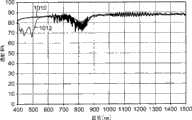
图10为所制造的两个双重双折射多层光学膜的测定光谱透射性的图;以及Figure 10 is a graph of the measured spectral transmission of two double birefringent multilayer optical films as produced; and
图11为光谱透射性的图,其上绘制有内部图案化的双重双折射多层光学膜的未处理和处理部分的测定数据,并且其上还绘制有膜的估算的数据。11 is a graph of spectral transmittance plotted with measured data for untreated and treated portions of an internally patterned double birefringent multilayer optical film and with estimated data for the films plotted thereon.
在这些附图中,相同的附图标号指示相同的元件。In these drawings, the same reference numerals indicate the same elements.
具体实施方式Detailed ways
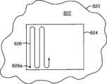
图1示出了多层光学膜110,该膜已利用内层(图1中未示出)中的至少一些的空间选择性双折射减少进行内部图案化或空间定制。内部图案化限定了不同区112、114、116,这些区被成形以便形成所示的标记“3M”。膜110示出为卷绕成卷的长挠性材料,因为本文所述的方法有利地与高容量滚筒式工艺相容。然而,该方法并不限于挠性卷状物品,并且可在小件部件或样品以及非挠性膜和制品上实施。Figure 1 illustrates a multilayer
“3M”标记为可见的,因为不同的区112、114、116具有不同的反射特性。在所示实施例中,区112具有第一反射特性,区114、116具有第二反射特性,第二反射特性不同于第一反射特性。通常但非必需的是,膜110将为至少部分透光的,在这种情况下,区112、114、116也将具有对应于其各自反射特性的不同透射特性。当然一般来讲,透射(T)加反射(R)加吸收(A)=100%,或T+R+A=100%。在一些实施例中,膜完全由在波长谱的至少一部分上具有低吸收的材料构成。这甚至对于掺入吸收染料或颜料以促进热递送的膜也可能是实际情况,因为某些吸收材料在其方面为波长特异性的。例如,可用的红外染料在近红外波长区中选择性地吸收,而在可见光谱中具有非常少的吸收。在光谱的另一端处,在多层光学膜文献中视为低损耗的多种聚合物材料在可见光谱上确实具有低损耗,但在某些紫外线波长下也具有显著的吸收。因此,在许多情况下,多层光学膜110可以在波长谱的至少限定部分上(例如可见光谱)具有微小或忽略不计的吸收,在这种情况下,该限定范围内的反射和透射呈现互补关系,因为T+R=100%-A,并且由于A小,The "3M" marking is visible because the
则T+R≈100%。Then T+R≈100%.
如将在下文进一步所述,第一反射特性和第二反射特性各归因于膜110内部的结构特征,而非归因于涂覆至膜表面的涂层或其它表面特征。本发明所公开的膜的此方面使其有利于用于安全用途(如其中膜旨在应用至产品、包装或文献作为真实性的指示物),因为内部特征难以复制或伪造。As will be described further below, the first and second reflective properties are each due to structural features within the
第一反射特性和第二反射特性在某些方面不同,这在至少某些观察条件下是明显的,以允许通过观察者或通过机器检测图案。在一些情况下,可能有利的是使在可见波长下的第一反射特性和第二反射特性之间的差异最大化,以使得图案在大部分观察和照明条件下对于人类观察者为明显的。在其它情况下,可能有利的是在第一反射特性和第二反射特性之间仅提供细微差异或提供仅在某些观察条件下明显的差异。在任一种情况下,第一反射特性和第二反射特性之间的差异都优选可主要归因于多层光学膜的内层在膜的不同相邻区中的折射率差值,并且并非主要归因于相邻区之间的厚度差值。The first reflective characteristic and the second reflective characteristic differ in some respect, which is apparent under at least some viewing conditions, to allow detection of the pattern by an observer or by a machine. In some cases, it may be desirable to maximize the difference between the first reflective property and the second reflective property at visible wavelengths so that the pattern is apparent to a human observer under most viewing and lighting conditions. In other cases, it may be desirable to provide only slight differences or differences that are only noticeable under certain viewing conditions between the first reflective characteristic and the second reflective characteristic. In either case, the difference between the first reflective property and the second reflective property is preferably attributable primarily to differences in the refractive indices of the inner layers of the multilayer optical film in different adjacent regions of the film, and is not primarily Attributed to the difference in thickness between adjacent regions.
区与区的折射率差值可根据多层光学膜的设计而产生第一反射特性和第二反射特性之间的各种差异。在一些情况下,第一反射特性可以包括第一反射谱带,第一反射谱带具有给定中心波长、谱带边缘和最大反射率,并且第二反射特性可以不同于第一反射特性,不同之处在于其具有第二反射谱带,第二反射谱带具有与第一反射谱带相似的中心波长和/或谱带边缘,而且具有与第一反射谱带显著不同(较高或较低)的最大反射率,或第二反射谱带可以基本上不存在于第二反射特性中。这些第一反射谱带和第二反射谱带可以根据膜的设计而与仅具有一种偏振态的光或具有任何偏振态的光相关。The difference in refractive index from zone to zone can produce various differences between the first reflective characteristic and the second reflective characteristic depending on the design of the multilayer optical film. In some cases, the first reflection characteristic may include a first reflection band having a given center wavelength, band edge, and maximum reflectivity, and the second reflection characteristic may be different from the first reflection characteristic by different The difference is that it has a second reflection band that has a similar center wavelength and/or bandedge to the first reflection band, and has a significantly different (higher or lower ), or the second reflectance band may be substantially absent from the second reflectance characteristic. These first and second reflection bands can be associated with light of only one polarization state or with light of any polarization state, depending on the design of the film.
在一些情况下,第一反射特性和第二反射特性可能在它们对视角的依赖性方面不同。例如,第一反射特性可以包括第一反射谱带,第一反射谱带具有给定中心波长、谱带边缘和垂直入射下的最大反射率,并且第二反射特性可以包括第二反射谱带,第二反射谱带在垂直入射下与第一反射谱带的这些方面非常相似。然而随着入射角的增大,尽管第一反射谱带和第二反射谱带均可能偏移为较短波长,但其各自的最大反射率可能极大地彼此偏移。例如,第一反射谱带的最大反射率可能一直为常数或随入射角的增大而增大,而第二反射谱带的最大反射率或至少其p偏振分量可能随入射角的增大而减小。In some cases, the first reflective characteristic and the second reflective characteristic may differ in their dependence on viewing angle. For example, the first reflection characteristic may comprise a first reflection band having a maximum reflectance at a given center wavelength, band edge and normal incidence, and the second reflection characteristic may comprise a second reflection band, The second reflection band is very similar in these respects to the first reflection band at normal incidence. However, as the angle of incidence increases, although both the first and second reflection bands may shift to shorter wavelengths, their respective maximum reflectivities may greatly shift from each other. For example, the maximum reflectance of the first reflection band may be constant or increase with increasing angle of incidence, while the maximum reflectance of the second reflection band, or at least its p-polarized component, may increase with increasing angle of incidence. decrease.
在其中第一反射特性和第二反射特性之间的上述差异与覆盖可见光谱的一部分的反射谱带相关的情况下,该差异可能被察觉为膜的第一区和第二区之间的颜色差异。In cases where the aforementioned difference between the first and second reflective properties is associated with a reflectance band covering a portion of the visible spectrum, the difference may be perceived as a color between the first and second regions of the film difference.
现在转向图2,该图示出多层膜210的一部分的示意性侧视图,以反映包括其内层的膜的结构。膜相对于局部x-y-z笛卡尔坐标系示出,其中膜平行于x轴和y轴延伸,并且z轴垂直于膜及其组成层且平行于膜的厚度轴。应当注意,膜210不必为完全平坦的膜,而且可以为弯曲的膜或者说是被成形为从平面偏离的膜,并且甚至在这些情况下,膜的任意小的部分或区可与所示的局部笛卡尔坐标系相关。膜210通常可以视为表示图1在其区112、114、116中的任何者中的膜110,因为膜110的各个层优选地从每一个这种区连续地延伸至下一个区。Turning now to FIG. 2 , this figure shows a schematic side view of a portion of a
多层光学膜包括各个层,该各个层具有不同折射率,以使得一些光在相邻层之间的界面处被反射。这些层(有时称为“微层”)为足够薄的,以使得在多个界面处反射的光发生相长干涉或相消干涉,以向多层光学膜赋予所需的反射或透射特性。对于设计用于反射紫外光、可见光或近红外波长光的多层光学膜而言,每一层微层的光学厚度(物理厚度乘以折射率)一般都为小于约1μm。然而,也可包括较厚的层,例如多层光学膜的外表面处的表层,或设置在多层光学膜内以分隔微层的相干分组(称为“叠堆”或“组”)的保护性边界层(PBL)。在图2中,微层标记为“A”或“B”,“A”层由一种材料构成,“B”层由不同的材料构成,这些层以交替排列的方式堆叠,以形成光学重复单元或单位单元ORU1、ORU2、…ORU6,如图所示。通常,如果需要高反射率,则完全由聚合物材料构成的多层光学膜将包括不止6个光学重复单元。应当注意,除了最上面的“A”层之外,图2所示的所有“A”和“B”微层均为膜210的内层,该最上面的“A”层的上表面在此示例性实例中与膜210的外表面210a一致。位于附图底部的显著较厚的层212可表示外表层或PBL,该PBL将图中所示的微层叠堆与另一个微层叠堆或组(未示出)分隔。如果需要,可(如)利用一层或多层厚粘合剂层或利用压力、热或其它方法将两种或更多种单独的多层光学膜层合在一起,以形成层合膜或复合膜。Multilayer optical films include individual layers that have different indices of refraction such that some light is reflected at interfaces between adjacent layers. These layers (sometimes referred to as "microlayers") are sufficiently thin such that light reflected at multiple interfaces interferes constructively or destructively to impart the desired reflective or transmissive properties to the multilayer optical film. For multilayer optical films designed to reflect light at ultraviolet, visible, or near-infrared wavelengths, the optical thickness (physical thickness times refractive index) of each microlayer is generally less than about 1 μm. However, thicker layers may also be included, such as skin layers at the outer surfaces of the multilayer optical film, or layers disposed within the multilayer optical film to separate coherent groupings of microlayers (referred to as "stacks" or "groups"). Protective boundary layer (PBL). In Figure 2, the microlayers are labeled "A" or "B", with layer "A" consisting of one material and layer "B" of a different material stacked in an alternating arrangement to create an optical repeat Units or unit units ORU1, ORU2, ... ORU6, as shown. Typically, multilayer optical films composed entirely of polymeric materials will include more than 6 optical repeat units if high reflectivity is desired. It should be noted that all of the "A" and "B" microlayers shown in FIG. Conforms to
在一些情况下,微层的厚度和折射率值可对应于1/4波长叠堆,即微层被布置成光学重复单元,每一个光学重复单元均具有两个等光学厚度(f-比率=50%,f-比率为组成层“A”的光学厚度与完整光学重复单元的光学厚度的比率)的相邻微层,这类光学重复单元通过相长干涉有效地反射光,被反射光的波长λ为光学重复单元总光学厚度的两倍,其中物体的“光学厚度”是指其物理厚度与其折射率的乘积。在其它情况下,光学重复单元中的微层的光学厚度可能彼此不同,由此f-比率为大于或小于50%。在图2的实施例中,一般起见,“A”层示出为比“B”层薄。每一个示出的光学重复单元(ORU1、ORU2等)的光学厚度(OT1、OT2等)都等于其组成“A”和“B”层的光学厚度之和,并且每一个光学重复单元都反射波长λ为其总光学厚度两倍的光。由通常用于多层光学膜中、以及用于本文具体所述的内部图案化多层膜中的微层叠堆或组提供的反射本质上通常为基本上镜面的而非漫射的,因为在微层之间具有基本光滑的界限清晰的界面,并且在通常的构造中使用低雾度材料。然而在一些情况下,成品可以被调控,以(如)利用表层和/或PBL层中的漫射材料和/或利用(例如)一个或多个表面漫射结构或纹理化表面来掺入任何所需程度的散射。In some cases, the thickness and refractive index values of the microlayers may correspond to a 1/4 wavelength stack, i.e., the microlayers are arranged into optical repeating units, each optical repeating unit having two equal optical thicknesses (f-ratio= 50%, the f-ratio is the ratio of the optical thickness of the constituent layer "A" to the optical thickness of the complete optical repeating unit) of adjacent microlayers, such optical repeating units effectively reflect light by constructive interference, the reflected light The wavelength λ is twice the total optical thickness of the optical repeating unit, where the "optical thickness" of an object is the product of its physical thickness and its refractive index. In other cases, the optical thicknesses of the microlayers in the optical repeat unit may differ from each other such that the f-ratio is greater or less than 50%. In the embodiment of FIG. 2, the "A" layer is shown to be thinner than the "B" layer for generality. Each optical repeat unit (ORU1, ORU2, etc.) shown has an optical thickness (OT1 ,OT2, etc.) Reflects light at wavelength λ twice its total optical thickness. Reflection provided by microlayer stacks or groups commonly used in multilayer optical films, as well as in the internally patterned multilayer films specifically described herein, is generally substantially specular rather than diffuse in nature because in The microlayers have substantially smooth well-defined interfaces and are typically constructed using low haze materials. In some cases, however, finished products can be tailored to incorporate any The desired degree of scattering.
在一些实施例中,层叠堆中的光学重复单元的光学厚度可以全部彼此相等,从而得到中心波长等于每一个光学重复单元的光学厚度两倍的具有高反射率的窄反射谱带。在其它实施例中,光学重复单元的光学厚度可以根据沿膜的z轴或厚度方向的厚度梯度而不同,由此随着从叠堆的一侧(如顶部)前进到叠堆的另一侧(如底部),光学重复单元的光学厚度会增加、减小或符合某些其它的函数关系。可使用这种厚度梯度,从而得到加宽的反射谱带,从而在所关注的扩展波长谱带以及所关注的所有角度上得到光的大致光谱上平坦的透射和反射。也可使用被调控、以在高反射和高透射之间的过渡波长下锐化谱带边缘的厚度梯度,如在美国专利6,157,490(Wheatley等人)的“Optical FilmWith Sharpened Bandedge”(具有锐化谱带边缘的光学膜)中所述。对于聚合物多层光学膜,反射谱带可被设计成具有锐化的谱带边缘以及“平顶”的反射谱带,其中反射特性在应用的整个波长范围内基本上是恒定的。还可以想到其它层布置方式,例如具有2微层光学重复单元的多层光学膜(其f-比率为不同于50%),或光学重复单元包括不止两层微层的膜。这些可供选择的光学重复单元设计可被配置成减少或激发某些更高阶的反射,当所需扩展波长谱带位于近红外波长内或延伸到近红外波长时,这样做可能是可用的。参见(如)以下美国专利:5,103,337(Schrenk等人)“Infrared Reflective Optical InterferenceFilm”(红外反射型光学干涉膜);5,360,659(Arends等人)“TwoComponent Infrared Reflecting Film”(两组分红外反射性膜);6,207,260(Wheatley等人)“Multicomponent Optical Body”(多组分光学体);和7,019,905(Weber)“Multi-layer Reflector With Suppression of HighOrder Reflections”(具有高阶反射抑制的多层反射器)。In some embodiments, the optical thicknesses of the optical repeat units in the stack may all be equal to each other, resulting in a narrow reflection band with high reflectivity at a center wavelength equal to twice the optical thickness of each optical repeat unit. In other embodiments, the optical thickness of the optical repeat unit may vary according to a thickness gradient along the z-axis or thickness direction of the film, whereby (eg bottom), the optical thickness of the optical repeat unit increases, decreases, or follows some other function. Such thickness gradients can be used to obtain broadened reflection bands, resulting in substantially spectrally flat transmission and reflection of light over the extended wavelength band of interest and all angles of interest. Thickness gradients tuned to sharpen bandedges at transition wavelengths between high reflection and high transmission can also be used, as in "Optical Film With Sharpened Bandedge" in U.S. Patent 6,157,490 (Wheatley et al.) Edged Optical Films). For polymeric multilayer optical films, the reflection bands can be engineered to have sharp band edges as well as "flat-topped" reflection bands, where the reflection characteristics are substantially constant over the entire wavelength range of the application. Other layer arrangements are also conceivable, such as multilayer optical films with 2 microlayer optical repeat units (with f-ratio other than 50%), or films with optical repeat units comprising more than two microlayers. These alternative optical repeat unit designs can be configured to reduce or excite certain higher order reflections, which may be available when the desired extended wavelength band lies within or extends to near-infrared wavelengths . See (eg) the following U.S. Patents: 5,103,337 (Schrenk et al.) "Infrared Reflective Optical Interference Film"; 5,360,659 (Arends et al.) "TwoComponent Infrared Reflecting Film" 6,207,260 (Wheatley et al.) "Multicomponent Optical Body"; and 7,019,905 (Weber) "Multi-layer Reflector With Suppression of High Order Reflections" (multilayer reflector with high-order reflection suppression).
如上所述,多层光学膜的相邻微层具有不同的折射率,以使得某些光在相邻层之间的界面处被反射。将微层之一(如图2中的“A”层)对沿主轴x轴、y轴和z轴偏振的光的折射率分别称为n1x、n1y和n1z。x轴、y轴和z轴可以(例如)对应于材料的介电张量的主方向。通常并且为了论述目的,不同材料的主方向为一致的方向,但一般不必如此。将相邻微层(如图2中的“B”层)沿相同轴的折射率分别称为n2x、n2y、n2z。将这些层之间沿x方向、沿y方向和沿z方向的折射率差值分别称为Δnx(=n1x-n2x)、Δny(=n1y-n2y)和Δnz(=n1z-n2z)。这些折射率差值的特性与膜中(或膜的给定叠堆中)的微层数量及其厚度分布结合来控制膜(或膜的给定叠堆)在给定区中的反射和透射特性。例如,如果相邻微层沿一个面内方向具有大的折射率失配(Δnx大),并且沿正交面内方向具有小的折射率失配(Δny≈0),则膜或组就垂直入射光而言可以起到反射型偏振器的作用。就这一点而言,出于本专利申请的目的,反射型偏振器可以视为这样的光学体,如果波长位于组的反射谱带内,则该光学体强烈反射沿一个面内轴(称为“阻光轴”)偏振的垂直入射光,并且强烈透射沿正交面内轴(称为“透光轴”)偏振的这种光。根据预期应用或应用领域,“强烈反射”和“强烈透射”可以根据预期应用或使用领域而具有不同的含义,但在许多情况下,反射型偏振器的反射率对于阻光轴将为至少70%、80%或90%,并且反射型偏振器的透射率对于透光轴将为至少70%、80%或90%。As noted above, adjacent microlayers of a multilayer optical film have different indices of refraction such that some light is reflected at the interface between adjacent layers. The refractive indices of one of the microlayers (such as layer "A" in FIG. 2) for light polarized along the principal axes x, y, and z are referred to as n1x, n1y, and n1z, respectively. The x-, y-, and z-axes may, for example, correspond to principal directions of the dielectric tensor of the material. Typically, and for purposes of discussion, the principal directions of different materials will be in the same direction, but generally this need not be the case. Refractive indices along the same axis of adjacent microlayers (such as layer “B” in FIG. 2 ) are referred to as n2x, n2y, and n2z, respectively. The refractive index differences between these layers along the x-direction, along the y-direction and along the z-direction are called Δnx (=n1x-n2x), Δny (=n1y-n2y) and Δnz (=n1z-n2z), respectively. The properties of these refractive index differences combined with the number of microlayers in the film (or in a given stack of films) and their thickness distribution control the reflection and transmission of the film (or a given stack of films) in a given region characteristic. For example, if adjacent microlayers have a large index mismatch along one in-plane direction (Δnx large) and a small index mismatch along the orthogonal in-plane direction (Δny≈0), then the film or group is vertical It acts as a reflective polarizer for incident light. In this regard, for the purposes of this patent application, a reflective polarizer may be considered an optical body that strongly reflects along an in-plane axis (called normal incident light polarized along the "block axis"), and such light polarized along the orthogonal in-plane axis (called the "pass axis") is strongly transmitted. "Strongly reflective" and "strongly transmissive" can have different meanings depending on the intended application or field of use, but in many cases the reflectance of a reflective polarizer will be at least 70 for the block axis %, 80% or 90%, and the transmittance of the reflective polarizer will be at least 70%, 80% or 90% with respect to the pass axis.
就本专利申请的目的而言,如果材料在所关注的波长范围(如光谱的UV部分、可见部分和/或红外部分中的选定波长或谱带)上具有各向异性的介电张量,则将该材料视为“双折射的”材料。换句话说,如果材料的主折射率(如n1x、n1y、n1z)并非全部相同,则将该材料视为“双折射的”材料。For the purposes of this patent application, if a material has an anisotropic dielectric tensor over the wavelength range of interest (e.g., selected wavelengths or bands in the UV, visible, and/or infrared portions of the spectrum) , the material is considered "birefringent". In other words, a material is considered "birefringent" if its principal indices of refraction (eg, n1x, n1y, n1z) are not all the same.
又如,相邻微层可以沿两个面内轴线均具有较大的折射率失配(Δnx大且Δny大),在这种情况下,膜或组可起到同轴反射镜的作用。就这一点而言,出于本专利申请的目的,如果波长位于组的反射谱带内,反射镜或反射镜状膜则可以视为强烈反射任何偏振的垂直入射光的光学体。再则,根据预期应用或应用领域,“强烈反射”可以具有不同的含义,但在多种情况下,反射镜对于在所关注波长下的任何偏振的垂直入射光的反射率将为至少70%、80%或90%。在上述实施例的变型中,相邻微层可以沿z轴具有折射率匹配或失配(Δnz≈0或Δnz大),并且该失配可以具有与面内折射率失配相同或相反的极性或标记。对Δnz的这种定制在斜入射光的p偏振分量的反射率无论是随入射角增大而增大、减小、还是保持不变都起关键作用。在另一个实例中,相邻微层可以沿这两个面内轴都具有显著的折射率匹配(Δnx≈Δny≈0),而沿z轴具有折射率失配(Δnz大),在这种情况下,如果波长位于组的反射谱带内,则膜或组可以起到所谓的“p偏振器”的作用,其强烈透射任何偏振的垂直入射光,而且渐增地反射入射角增大的p偏振光。As another example, adjacent microlayers may have large refractive index mismatches along both in-plane axes (Δnx large and Δny large), in which case the film or set can act as an in-line mirror. In this regard, for the purposes of this patent application, a mirror or mirror-like film may be considered an optical body that strongly reflects normally incident light of any polarization if the wavelength lies within the group's reflection band. Again, "strongly reflective" can have different meanings depending on the intended application or field of application, but in many cases the reflectivity of the mirror will be at least 70% for normally incident light of any polarization at the wavelength of interest , 80% or 90%. In variations of the above embodiments, adjacent microlayers may have a refractive index match or mismatch along the z-axis (Δnz≈0 or Δnz is large), and this mismatch may have the same or opposite polarity as the in-plane refractive index mismatch. sex or mark. This tailoring of Δnz plays a key role in whether the reflectivity of the p-polarized component of obliquely incident light increases, decreases, or remains constant with increasing incidence angle. In another example, adjacent microlayers can have significant index matching along both in-plane axes (Δnx≈Δny≈0) and index mismatch along the z-axis (large Δnz), in which In some cases, if the wavelength lies within the reflection band of the group, the film or group can act as a so-called "p-polarizer", which strongly transmits normal incident light of any polarization and progressively reflects light at increasing angles of incidence. p-polarized light.
如果膜210为双重双折射多层光学膜,则图2中的“A”层和“B”层均为双折射层。换句话说,“A”层并非为各向同性的层,并且“B”层也并非为各向同性的层。另外换句话说,并非n1x=n1y=n1z,并且也并非n2x=n2y=n2z。因此,对于双折射的“A”层,n1x、n1y和n1z中的至少一个显著不同于n1x、n1y和n1z中的至少另一个。并且对于双折射的“B”层,n2x、n2y和n2z中的至少一个显著不同于n2x、n2y和n2z中的至少另一个。If
根据沿不同轴的可能折射率差值的大量排列、层的总数量及其厚度分布、以及包括在多层光学膜中的微层组的数量和类型,则可能的多层光学膜210及其组的种类是巨大的。示例性的多层光学膜公开于:美国专利5,486,949(Schrenk等人)“Birefringent Interference Polarizer”(双折射干涉偏振器);美国专利5,882,774(Jonza等人)“Optical Film”(光学膜);美国专利6,045,894(Jonza等人)“Clear to Colored SecurityFilm”(透明至彩色安全膜);美国专利6,179,949(Merrill等人)“OpticalFilm and Process for Manufacture Thereof”(光学膜及其制造方法);美国专利6,531,230(Weber等人)“Color Shifting Film”(色移膜);美国专利6,939,499(Merrill等人)“Processes and Apparatus for MakingTransversely Drawn Films with Substantially Uniaxial Character”(用于制备具有显著单轴特性的横向拉延膜的方法和装置);美国专利7,256,936(Hebrink等人)“Optical Polarizing Films with Designed ColorShifts”(具有设计色移的光学偏振膜);美国专利7,316,558(Merrill等人)“Devices for Stretching Polymer Films”(用于拉伸聚合物膜的设备);PCT公布WO 2008/144136A1(Nevitt等人)“Lamp-HidingAssembly for a Direct Lit Backlight”(用于直接照明式背光源的隐灯组件);PCT公布WO 2008/144656A2(Weber等人)“Backlight and DisplaySystem Using Same”(背光源及其使用显示系统)。Depending on the vast array of possible refractive index differences along different axes, the total number of layers and their thickness distributions, and the number and type of microlayer groups included in the multilayer optical film, the possible multilayer
应当注意,多层光学膜的至少一个组中的微层中的至少一些在膜的至少一个区(如图1中的区112、114、116)中为双折射的层。对于双重双折射微层组,光学重复单元中的第一层为双折射层(即n1x≠n1y或n1x≠n1z或n1y≠n1z),并且光学重复单元中的第二层也为双折射层(即n2x≠n2y或n2x≠n2z或n2y≠n2z)。此外,一层或多层这种层的双折射相对于相邻区在至少一个区中的双折射得以减少。在一些情况下,这些层的双折射可以减少至零,使得它们在该区之一中为光学各向同性的层(即n1x=n1y=n1z或n2x=n2y=n2z),而在相邻区中为双折射层。在其中两层初始均为双折射层的情况下,根据材料选择和处理条件,这些层可通过下述方式进行处理,即显著减少仅该层之一的双折射,或可减少全部两层的双折射。It should be noted that at least some of the microlayers in at least one group of the multilayer optical film are birefringent layers in at least one region of the film (eg,
示例性多层光学膜由聚合物材料构成,并且可利用共挤出、浇铸和取向工艺来制备。参见以下美国专利:5,882,774(Jonza等人)“OpticalFilm”(光学膜)、6,179,949(Merrill等人)“Optical Film and Processfor Manufacture Thereof”(光学膜及其制造方法)和6,783,349(Neavin等人)“Apparatus for Making Multilayer Optical Films”(用于制备多层光学膜的设备)。多层光学膜可如上述任何参考文献中所述通过聚合物的共挤出来形成。优选的是,选择各种层的聚合物使之具有相似的流变性(如熔体粘度),以使得它们可进行共挤出而没有显著的流体扰动。选择挤出条件,以便以连续稳定的方式将各自的聚合物充分地进料、熔融、混合并作为进料流或熔融流泵送。用于形成和保持熔融流中的每一股的温度可以选定为在下述范围内,所述范围避免冻结、结晶、或该温度范围的低端处的不当高压下降、并且避免该范围的高端处的材料降解。Exemplary multilayer optical films are composed of polymeric materials and can be prepared using coextrusion, casting, and orientation processes. See the following U.S. Patents: 5,882,774 (Jonza et al.) "Optical Film", 6,179,949 (Merrill et al.) "Optical Film and Process for Manufacture Thereof" and 6,783,349 (Neavin et al.) "Apparatus for Making Multilayer Optical Films" (equipment for making multilayer optical films). Multilayer optical films can be formed by coextrusion of polymers as described in any of the above references. Preferably, the polymers of the various layers are selected to have similar rheology (eg, melt viscosity) so that they can be coextruded without significant fluid disturbance. Extrusion conditions are selected so that the respective polymers are adequately fed, melted, mixed and pumped as a feed or melt stream in a continuous and stable manner. The temperature for forming and maintaining each strand in the molten stream can be selected within a range that avoids freezing, crystallization, or undue high pressure drop at the low end of the temperature range and avoids the high end of the range where the material degrades.
简而言之,该制备方法可以包括:(a)提供至少第一树脂流和第二树脂流,至少第一树脂流和第二树脂流与有待用于成品膜中的第一聚合物和第二聚合物对应;(b)利用合适的送料区块将第一树脂流和第二树脂流分成多层,例如包括以下设施的送料区块:(i)梯度板,其具有第一流动通道和第二流动通道,其中第一通道的横截区沿该流动通道从第一位置变化到第二位置,(ii)进料管板,其具有与第一流动通道流体连通的第一多导管和与第二流动通道流体连通的第二多导管,每一根导管都向其自身的相应狭槽模具进料,每一根导管都具有第一末端和第二末端,导管的第一末端与流体通道流体连通,并且导管的第二末端与狭槽模具流体连通,和(iii)任选的邻近所述导管设置的轴向棒形加热器;(c)使复合材料流穿过挤出模具以形成多层料片,其中每一层都大致平行于相邻层的主表面;以及(d)将多层料片浇铸到冷却辊(有时也称为浇铸轮或浇铸辊)上,以形成浇铸的多层膜。该浇铸膜可以与成品膜具有相同的层数,但该浇铸膜的层通常比成品膜的层厚得多。此外,浇铸膜的层通常都是各向同性的层。Briefly, the manufacturing method may include: (a) providing at least a first resin stream and a second resin stream, at least the first resin stream and the second resin stream together with the first polymer and the second resin stream to be used in the finished film Two polymer correspondences; (b) dividing the first resin flow and the second resin flow into multiple layers using a suitable feedblock, such as a feedblock comprising: (i) a gradient plate having a first flow channel and A second flow channel along which the cross-sectional area of the first channel changes from a first position to a second position, (ii) a feed tube sheet having a first multi-conduit in fluid communication with the first flow channel and a second plurality of conduits in fluid communication with the second flow channel, each conduit feeding into its own corresponding slot die, each conduit having a first end and a second end, the first end of the conduit being in contact with the fluid the channel is in fluid communication with the second end of the conduit and the slot die, and (iii) an optional axial rod heater disposed adjacent to the conduit; (c) passing the flow of composite material through the extrusion die to forming a multilayer web in which each layer is substantially parallel to the major surfaces of adjacent layers; and (d) casting the multilayer web onto chilled rolls (also sometimes referred to as casting wheels or rolls) to form a cast multilayer film. The cast film can have the same number of layers as the finished film, but the layers of the cast film are usually much thicker than the layers of the finished film. Furthermore, the layers of the cast film are generally all isotropic layers.
浇铸多层料片也可使用许多替代方法来制备。美国专利5,389,324(Lewis等人)中描述了一种替代方法,该方法也利用聚合物共挤出。Cast multilayer webs can also be prepared using a number of alternative methods. An alternative method is described in US Patent 5,389,324 (Lewis et al.), which also utilizes polymer coextrusion.
冷却后,可拉延或拉伸多层料片以制备近成品多层光学膜,其细节可见于上述引用的参考文献中。拉延或拉伸实现以下两个目标:它将层薄化到其所需的最终厚度,并且它将层取向,使得层中的至少一些变为双折射的层。可按以下方向同时或顺序地实现取向或拉伸:沿料片横向方向(如经由拉幅机);沿纵维方向(如经由长度取向机);或它们的任何组合。如果仅沿一个方向拉伸,则该拉伸可为“无约束的”(其中膜允许在垂直于拉伸方向的面内方向在尺寸上松弛)或“受约束的”(其中膜为受约束的并因而不允许在垂直于拉伸方向的面内方向在尺寸上松弛)。如果沿两个面内方向拉伸,则该拉伸可为对称的(即沿正交的面内方向相等)或非对称的拉伸。或者,膜可以通过间歇工艺进行拉伸。在任何情况下,也都可将后续或共存拉延减小、应力或应变平衡、热定形、和其它处理操作应用至膜。After cooling, the multilayer web can be drawn or stretched to produce a near-finished multilayer optical film, details of which can be found in the references cited above. Drawing or stretching accomplishes two goals: it thins the layers to their desired final thickness, and it orients the layers such that at least some of the layers become birefringent. Orientation or stretching can be accomplished simultaneously or sequentially: in the transverse direction of the web (eg, via a tenter frame); in the machine direction (eg, via a length orienter); or any combination thereof. If stretched in only one direction, the stretch can be "unconstrained" (where the film is allowed to relax dimensionally in the in-plane direction perpendicular to the stretching direction) or "constrained" (where the film is constrained and thus does not allow dimensional relaxation in the in-plane direction perpendicular to the stretching direction). If stretched in two in-plane directions, the stretch may be symmetrical (ie, equal in the orthogonal in-plane directions) or asymmetrical. Alternatively, the film can be stretched by a batch process. In any case, subsequent or concurrent draw reduction, stress or strain equalization, heat setting, and other processing operations may also be applied to the film.
多层光学膜和膜主体也可包括附加层和涂层,该层根据其光学、机械和/或化学特性进行选择。例如,可在膜的一个或两个主表面上添加UV吸收层,以保护膜不会发生由UV光引起的长期降解。附加层和涂层也可包括抗刮涂层、抗撕层和硬化剂。参见例(如)美国专利6,368,699(Gilbert等人)。Multilayer optical films and film bodies may also include additional layers and coatings, the layers being selected for their optical, mechanical and/or chemical properties. For example, a UV absorbing layer can be added to one or both major surfaces of the film to protect the film from long-term degradation caused by UV light. Additional layers and coatings may also include scratch-resistant coatings, tear-resistant layers, and hardeners. See, eg, US Patent 6,368,699 (Gilbert et al.).
在一些情况下,构成多层光学膜的聚合物材料组分中的一种、一些、或全部的天然吸收率或固有吸收率可以用于吸收性加热过程。例如,在可见光区上为低损耗的多种聚合物在某些紫外线波长下具有显著较高的吸收率。将膜的部分暴露于具有这种波长的光,可以用于选择性加热膜的这种部分。In some cases, the natural or intrinsic absorptivity of one, some, or all of the polymeric material components making up the multilayer optical film may be used in the absorptive heating process. For example, many polymers that are low loss in the visible region have significantly higher absorbance at certain ultraviolet wavelengths. Exposing portions of the film to light having such wavelengths can be used to selectively heat such portions of the film.
在其它情况下,可将吸收染料、颜料、或其它试剂掺入到多层光学膜的各个层中的一些或全部中,以促进上述吸收性加热。在一些情况下,这种吸收剂为具有光谱选择性的吸收剂,由此它们在一个波长区中吸收而在另一个波长区中不吸收。例如,本发明所公开的膜中的一些可以旨在用于可见光区中,例如,用于防伪安全标签上或用作液晶显示器(LCD)设备或其它显示设备的元件,在这种情况下,可以使用吸收红外线或紫外线波长而不显著吸收可见光波长的吸收剂。另外,可以将吸收剂掺入到膜的一层或多层选定层中。例如,膜可以包括两个由光学厚层(例如保护性边界层(PBL)、层合粘合剂层、一层或多层表层等)分隔的不同微层组,并且可以将吸收剂掺入到组中的一个中而非另一个中,或可以掺入到全部两个组中,但在一个组中相对于另一个组具有较高的浓度。In other cases, absorbing dyes, pigments, or other agents may be incorporated into some or all of the various layers of the multilayer optical film to facilitate the above-described absorptive heating. In some cases, such absorbers are spectrally selective absorbers whereby they absorb in one wavelength region and not in another. For example, some of the disclosed films may be intended for use in the visible region, for example, on anti-counterfeiting security labels or as elements of liquid crystal display (LCD) devices or other display devices, in which case, Absorbers that absorb infrared or ultraviolet wavelengths without significantly absorbing visible wavelengths can be used. Additionally, absorbers may be incorporated into one or more selected layers of the film. For example, a film may comprise two different sets of microlayers separated by an optically thick layer (e.g., a protective boundary layer (PBL), a laminating adhesive layer, one or more skin layers, etc.), and absorbers may be incorporated into into one of the groups but not the other, or can be incorporated into both groups, but at a higher concentration in one group relative to the other.
可使用多种吸收剂。对于在可见光谱中操作的光学膜,可以使用在紫外线和红外线(包括近红外)区中吸收的染料、颜料或其它添加剂。在一些情况下,可能有利的是,选择在下述光谱范围内吸收的试剂,对于所述光谱范围,膜的聚合物材料具有显著较低的吸收。通过将这种吸收剂掺入到多层光学膜的选定层中,定向辐射可优先地将热递送至选定层而非膜的整个厚度上。示例性的吸收剂可以为可熔融挤出的,以使得它们可嵌入到所关注的选定组中。为此,吸收剂优选在挤出所需的加工温度和停留时间下为适当稳定的吸收剂。有关合适吸收剂的其它信息,参见美国专利6,207,260(Wheatley等人)“Multicomponent Optical Body”(多组分光学体)。A variety of absorbents can be used. For optical films that operate in the visible spectrum, dyes, pigments or other additives that absorb in the ultraviolet and infrared (including near infrared) regions can be used. In some cases it may be advantageous to select an agent that absorbs in the spectral range for which the polymeric material of the film has significantly lower absorption. By incorporating such absorbers into selected layers of a multilayer optical film, directed radiation can preferentially deliver heat to selected layers rather than the entire thickness of the film. Exemplary absorbents may be melt-extrudable so that they can be embedded in selected groups of interest. For this reason, the absorbent is preferably a suitably stable absorbent at the processing temperatures and residence times required for extrusion. See US Patent 6,207,260 (Wheatley et al.) "Multicomponent Optical Body" for additional information on suitable absorbers.
现在转向图3,该图示出图1的多层光学膜110的位于区118(在区112和区116的边界处)附近的部分的示意性剖视图。在膜110的此展开图中,可观察到狭窄过渡区115将区112与相邻区116间隔。根据处理细节,这种过渡区可能存在或可能不存在,并且如果其不存在,则区116可以紧邻区112且无明显的居间特征。也可观察到膜110的构造细节:膜包括其相对侧上的光学厚表层310、312,以及设置在表层310、312之间的多层微层314和另一多层微层316。微层314、316中的全部均因外表层而位于膜110内部。在附图中,微层314和316之间的空间留有空白,以允许存在下述情况:其中微层314、316为起始于一层表层310且终止于相对表层312的单个微层组的部分,并且其中微层314、316为两个或更多个不同微层组的部分,该微层组通过一层或多层光学厚保护性边界层(PBL)或其它光学厚内层而彼此间隔。在任一种情况下,微层314、316优选都各包括设置成光学重复单元的两种交替聚合物材料,微层314、316中的每一层都以侧向或横向方式从区112连续延伸到相邻区116,如图所示。微层314、316在区112中通过相长干涉或相消干涉提供第一反射特性,并且微层314、316中的至少一些为双折射的层。区115、116可以此前已具有与区112相同的特性,但已通过向其选择性施加热进行处理,所述加热量足以减少或消除区116中的微层314、316中的一些的双折射,同时保持区112中的微层的双折射,所述热量也为足够低,以保持处理区116中的微层314、316的结构完整性。区116中的微层314、316的减少双折射是形成区116的第二反射特性的主要原因,第二反射特性不同于区112的第一反射特性。Turning now to FIG. 3 , a schematic cross-sectional view of a portion of multilayer
膜110在区112中具有特征厚度d1、d2,并且在区116中具有特征厚度d1’、d2’,如图所示。厚度d1、d1’为在各自的区中从膜的前外表面到膜的后外表面测定的物理厚度。厚度d2、d2’为从设置为最靠近膜的前表面的微层(在微层组的一个末端处)到设置为最靠近膜的后表面的微层(在相同或不同微层组的末端处)测定的物理厚度。因此,如果希望将膜110在区112中的厚度与膜在区116中的厚度进行比较,则可以选择比较d1与d1’、或d2与d2’,这取决于哪一种测定更方便。在大多数情况下,d1和d1’之间的比较可以与d2和d2’之间的比较适当地产生基本上相同的结果(成比例)。(当然,在其中膜不含外表层并且其中微层组在膜的两个外表面处均端接的情况下,d1和d2变为相同。)然而,如果存在显著偏差,例如如果表层从一个位置到另一个位置经历显著的厚度变化,但基础微层中不存在相应厚度变化,或反之亦然,则可能有利的是使用d2和d2’参数来更好地表征不同区中的整体膜厚度,这基于下述事实,即表层相比于微层组对膜的反射特性通常具有较小的影响。
当然,对于包含两个或更多个通过光学厚层彼此间隔的不同微层组的多层光学膜,任何给定微层组的厚度也可进行测定并且表征为从组中的第一微层到最末微层沿z轴的距离。该信息在比较不同区112、116中的膜110的物理特征的更深入分析中可能变得重要。Of course, for multilayer optical films comprising two or more different groups of microlayers separated from each other by an optically thick layer, the thickness of any given group of microlayers can also be determined and characterized as the first microlayer in the group. The distance along the z-axis to the last microlayer. This information may become important in a deeper analysis comparing the physical characteristics of the
如上所述,区116已利用下述方式进行处理,即选择性地施加热以引起微层314、316中的至少一些相对于它们在相邻区112中的双折射损失其双折射中的一些或全部,使得归因于来自微层的光的相长干涉或相消干涉的区116的反射特性不同于区112的反射特性。选择性加热过程可能涉及未向区116选择性地施加压力,并且其可能对膜基本上未导致显著的厚度变化(无论使用参数d1/d1’还是使用参数d2/d2’)。例如,膜110在区116中的平均厚度与在区112中的平均厚度偏差可能不超过在区112中或在未处理膜中观察到的厚度的垂直变化。因此,在对区116进行热处理之前,膜110在区112中、或在膜覆盖区112和区116的一部分的面积上可以具有厚度变化(d1或d2)Δd,并且区116的空间平均厚度d1’、d2’与区112中的空间平均厚度d1、d2(各自地)可以相差不超过Δd。参数Δd可以表示(例如)厚度d1或d2的空间分布中的一个、两个、或三个标准偏差。As noted above,
在一些情况下,区116的热处理可能产生膜在区116中的某些厚度变化。这些厚度变化可以是(例如)构成多层光学膜的不同材料的局部收缩和/或伸展所引起,或可以是某些其它的热诱导现象所引起。然而,在对处理区116的反射特性的影响上,与处理区中的双折射的减少或消除起到的主要作用相比,这种厚度变化(如果其发生)仅起到次要作用。另外应当注意,在多种情况下,可能有利的是在实现内部图案化的选择性热处理期间保持膜边缘承受张力,以便避免膜起皱或出于其它原因。所施加张力的量和热处理的细节也可以导致处理区中的某些量的厚度变化。In some cases, heat treatment of
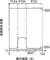
在一些情况下,可以通过分析膜的反射特性来区分厚度变化和双折射变化的影响。例如,如果未处理区(如区112)中的微层提供由左谱带边缘(LBE)、右谱带边缘(RBE)、中心波长λc和峰值反射率R1表征的反射谱带,则对于处理区,这些微层的给定厚度变化(其中微层的折射率无变化)将产生下述反射谱带,该反射谱带具有与R1约相等的峰值反射率R2,但相对于未处理区的反射谱带的那些特征却具有在波长中成比例偏移的LBE、RBE和中心波长,并且这种偏移可进行测定。另一方面,双折射的变化通常将在LBE波长、RBE波长和中心波长中仅产生极小的偏移,因为双折射变化引起的光学厚度变化通常非常小(重申光学厚度等于物理厚度乘以折射率)。然而,双折射的变化可对反射谱带的峰值反射率具有大的或至少显著的影响,这取决于微层叠堆的设计。因此,在一些情况下,双折射变化可能为被修改区中的反射谱带提供峰值反射率R2,其明显不同于R1,其中R1和R2当然是在相同照射和观察条件下进行比较的。如果以百分比表示R1和R2,则R2与R1可能相差至少10%或至少20%或至少30%。作为阐明实例,R1可以为70%,R2可以为60%、50%、40%或更小。或者,R1可以为10%,R2可以为20%、30%、40%或更大。R1和R2也可以通过采用其比率进行比较。例如,R2/R1或其倒数可以为至少2或至少3。In some cases, the effects of changes in thickness and changes in birefringence can be distinguished by analyzing the reflective properties of the film. For example, if a microlayer in an untreated region (such as region 112) provides a reflection band characterized by a left band edge (LBE), a right band edge (RBE), a central wavelengthλ , and a peak reflectanceR , then For the treatment zone, a given change in thickness of these microlayers (with no change in the refractive index of the microlayers) will produce a reflectance band with a peak reflectivityR2 approximately equal toR1 , but relative to Those features of the reflection bands of the untreated region, however, have LBE, RBE and center wavelengths that are proportionally shifted in wavelength, and this shift can be measured. On the other hand, changes in birefringence will generally produce only minimal shifts in the LBE wavelength, RBE wavelength, and center wavelength, since the change in optical thickness caused by a change in birefringence is usually very small (reiterating that optical thickness equals physical thickness times refraction Rate). However, changes in birefringence can have a large or at least significant effect on the peak reflectivity of the reflection band, depending on the design of the microlayer stack. Thus, in some cases, the change in birefringence may provide a peak reflectanceR2 for the reflection band in the modified region, which is significantly different fromR1 , whereR1 andR2 are of course performed under the same illumination and observation conditions Comparison of. If R1 and R2 are expressed as percentages, R2 may differ from R1 by at least 10%, or at least 20%, or at least 30%. As an illustrative example,R1 may be 70% andR2 may be 60%, 50%, 40% or less. Alternatively,R1 can be 10% andR2 can be 20%, 30%, 40% or more.R1 andR2 can also be compared by taking their ratios. For example, R2 /R1 or its inverse may be at least 2 or at least 3.
由于双折射变化引起的相邻层之间的折射率差值的变化所致的峰值反射率在其表征界面反射率变化程度(有时称为光焦度)的显著变化,通常也伴有反射谱带带宽的至少一些变化,其中带宽是指LBE和RBE之间的间距。Significant changes in peak reflectivity due to changes in the refractive index difference between adjacent layers due to changes in birefringence, which characterize the degree of change in interfacial reflectivity (sometimes called optical power), are often accompanied by reflectance spectra At least some variation of band bandwidth, where bandwidth refers to the spacing between LBE and RBE.
如上所述,在一些情况下,即使实际上在热处理期间未向区116施加选择性压力,膜110在处理区116中的厚度(即d1’或d2’)也可能稍不同于膜在未处理区112中的厚度。针对此原因,图3将d1’示出为稍不同于d1,并且将d2’示出为稍不同于d2。为一般起见,也示出了过渡区115,以表明在膜的外表面上由于选择性热处理可能存在“隆起块”或其它可检测人工痕迹。然而,在一些情况下,该处理可能未在相邻的处理区和未处理区之间导致可检测人工痕迹。例如,在一些情况下,在区间的整个边界上滑动其手指的观察者可能在区间未检测到隆起块、脊、或其它物理人工痕迹。As noted above, in some cases, the thickness of the
在一些情况下,处理区和未处理区之间的厚度差在膜的整个厚度上可能是不成比例的。例如,在一些情况下,可能的是,处理区和未处理区之间的外表层具有相对较小的厚度差(表示为变化百分比),而相同区间的一个或多个内部微层组可能具有较大的厚度差(表示为变化百分比)。In some cases, the difference in thickness between treated and untreated regions may not be proportional to the overall thickness of the film. For example, in some cases it may be possible that the outer skin layer between a treated and untreated zone has a relatively small difference in thickness (expressed as a percent change), while one or more inner microlayer groups in the same interval may have Larger thickness differences (expressed as percent change).
图4示出包含内部图案化的另一种多层光学膜410的一部分的示意性剖视图。膜410包含外部光学厚表层412、414和位于夹在表层之间的层416中的微层组。所有微层均在膜410内部。(在可供选择的实施例中,可以省略一层或两层表层,在这种情况下,组中的PBL中的一者或全部两者或最外微层可以成为外层。)微层包括的至少一些微层在膜的至少一些区或区域中为双折射的层,且至少在膜的相邻区之间以侧向或横向方式延伸。微层至少在膜的第一未处理区422中提供与光的相长干涉或相消干涉相关联的第一反射特性。膜410在相邻区420、424中已进行选择性加热,但未选择性地向这些区施加任何压力,以便得到也与光的相长干涉或相消干涉相关联、但不同于第一反射特性的第二反射特性。这些反射特性差异对于观察者可以视为在反射光或透射光中的处理区和未处理区之间的颜色差异。各自的颜色以及两者间的差异通常也随入射角而变化或偏移。膜410在区420、422、424中可以具有基本上相同的膜厚度,或膜厚度在这些区之间可能有一定程度的差异,但区间的膜厚度差并非对于第一反射特性和第二反射特性之间的差异起主要作用。区420、422、424形成膜内部的图案,如通过层416中的剖面影线所示。剖面影线指示出,与其在区422或其它未处理区中的双折射相比,剖面影线区中的微层中的至少一些具有减少的双折射(包括零双折射)。4 shows a schematic cross-sectional view of a portion of another multilayer
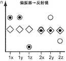
现在将注意力转向图5A-N中的理想化图。这些图有助于解释多层光学膜的图案化过程,其中特别强调地是双重双折射多层光学膜。这些图也有助于解释未处理区和处理区中各自的第一反射特性和第二反射特性的不同可能组合中的一些以及它们实现的方式。为说明起见,可以将光学膜的未处理区和处理区两者的反射特性分类成下述三种类型之一:类反射镜反射特性、类窗口反射特性、以及类偏振器反射特性。类反射镜反射特性对垂直入射光的所有偏振态均具有高反射率(如在一些情况下,大于50%、60%、70%、80%、90%、95%或99%),类窗口反射特性对垂直入射光的所有偏振态均具有低反射率(如在一些情况下,小于20%、10%、5%、3%或1%),类偏振器反射特性对一个偏振态的垂直入射光具有高反射率(如在一些情况下,大于50%、60%、70%、80%、90%、95%或99%),而对不同偏振态的垂直入射光具有低反射率(如在一些情况下,小于30%、20%、10%、5%、3%或1%)。(或者,类反射型偏振器特性可以一种偏振态相对于另一种偏振态的反射率差值来表示。)本文读者应当记住,除非另外指明,否则本文所述的与多层光学膜或叠堆相关的反射率值应当视为不包括在外部空气/聚合物界面处的菲涅耳反射。Attention is now turned to the idealized diagrams in Figures 5A-N. These figures help explain the patterning process of multilayer optical films, with particular emphasis on double birefringent multilayer optical films. These figures also help to explain some of the different possible combinations of the respective first and second reflective properties in the untreated and treated areas and how they are achieved. For purposes of illustration, the reflective properties of both untreated and treated regions of an optical film can be classified into one of three types: mirror-like reflective properties, window-like reflective properties, and polarizer-like reflective properties. Mirror-like reflective properties with high reflectivity (eg, in some cases greater than 50%, 60%, 70%, 80%, 90%, 95%, or 99%) for all polarization states of normally incident light, window-like The reflective properties have low reflectivity (e.g., in some cases less than 20%, 10%, 5%, 3% or 1%) for all polarization states of normally incident light, polarizer-like reflective properties for one polarization state Incident light has a high reflectivity (such as, in some cases, greater than 50%, 60%, 70%, 80%, 90%, 95%, or 99%), and has a low reflectivity ( As in some instances, less than 30%, 20%, 10%, 5%, 3% or 1%). (Alternatively, reflective polarizer-like properties may be expressed as the difference in reflectance of one polarization state relative to the other.) The reader of this document should keep in mind that unless otherwise indicated, the terms described herein are not compatible with multilayer optical films. Or stack-dependent reflectance values should be considered to exclude Fresnel reflections at the external air/polymer interface.
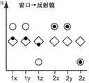
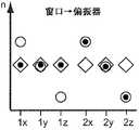
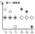
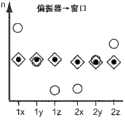
这些不同特性(如视为“高”反射率和视为“低”反射率的特性)的边界或极限以及两者间的差异可能取决于最终用途和/或系统需求。例如,可以将对于所有偏振态均具有适当程度的反射率的多层光学膜或其微层组视为用于某些应用的反射镜和用于其它应用的窗口。相似地,可以将对于垂直入射光的不同偏振态具有适当不同程度的反射率的多层光学膜或其微层组视为用于某些应用的偏振器、用于其它应用的反射镜、以及用于另外其它应用的窗口,这取决于精确反射率值以及给定最终用途对于不同偏振态的反射率差值的敏感性。除非另外指明,否则反射镜、窗口、和偏振器类别专门用于垂直入射光。本文读者应当理解,斜角特性与光学膜在垂直入射下的特性在一些情况下可能相同或相似、并且在其它情况下可能极度不同。The boundaries or limits of, and differences between, these different properties (eg, what is considered "high" reflectivity versus what is considered "low" reflectivity) may depend on the end use and/or system requirements. For example, a multilayer optical film, or microlayer array thereof, that has an appropriate degree of reflectivity for all polarization states can be considered a mirror for some applications and a window for others. Similarly, multilayer optical films or microlayer assemblies thereof having suitably different degrees of reflectivity for different polarization states of normally incident light can be considered polarizers for some applications, mirrors for other applications, and Windows for yet other applications, depending on the exact reflectance value and the sensitivity of a given end use to differences in reflectivity for different polarization states. Unless otherwise specified, the Mirror, Window, and Polarizer categories are specific to normal incidence light. Readers herein should understand that the off-angle properties and the properties of the optical film at normal incidence may in some cases be the same or similar, and in other cases may be drastically different.
在图5A-N的图中的每一个中,相对折射率“n”标绘在竖轴上。在水平轴上,为表征双层光学重复单元的六个折射率的每一个都提供位置或标记:“1x”、“1y”和“1z”表示第一层沿x轴、y轴和z轴的折射率,其在上文中被称为n1x、n1y和n1z。同样,“2x”、“2y”和“2z”表示第二层沿x轴、y轴和z轴的折射率,其在上文中被称为n2x、n2y和n2z。图中的菱形符号(◇)表示材料在第一处理阶段中的折射率。此第一阶段可以对应于下述聚合物层,该聚合物层(例如)已被挤出并且骤冷或浇铸到浇铸轮上、但仍未被拉伸或者说是取向。图中的空心(未填充)圆形符号(○)表示材料在晚于第一阶段的第二处理阶段中的折射率。第二阶段可以对应于已被拉伸或者说是取向成多层光学膜的聚合物层,多层光学膜通过相长干涉或相消干涉反射来自膜内的微层间的界面的光。图中的小填充圆形符号或点(●)表示材料在晚于第一阶段和第二阶段的第三处理阶段中的折射率。第三阶段可以对应于在被挤出和取向之后已被选择性热处理的聚合物层,如下文进一步所述。这种热处理通常限于膜的一个或多个特定部分或区,其称为处理区。In each of the graphs of Figures 5A-N, the relative refractive index "n" is plotted on the vertical axis. On the horizontal axis, positions or labels are provided for each of the six indices of refraction that characterize the bilayer optical repeat unit: "1x", "1y" and "1z" denote the first layer along the x-, y-, and z-axes The refractive indices of , which are referred to above as n1x, n1y and n1z. Likewise, "2x", "2y" and "2z" represent the refractive indices of the second layer along the x-axis, y-axis and z-axis, which are referred to as n2x, n2y and n2z above. The diamond symbol (◇) in the figure indicates the refractive index of the material in the first processing stage. This first stage may correspond to a polymer layer that has, for example, been extruded and quenched or cast onto a casting wheel, but has not yet been stretched or oriented. The open (unfilled) circular symbols (◯) in the figure indicate the refractive index of the material in the second processing stage later than the first stage. The second stage may correspond to a polymer layer that has been stretched or otherwise oriented into a multilayer optical film that reflects light from interfaces between microlayers within the film by constructive or destructive interference. The small filled circle symbols or dots (•) in the figure represent the refractive index of the material in a third processing stage later than the first and second stages. The third stage may correspond to the polymer layer which has been optionally heat treated after being extruded and oriented, as further described below. This heat treatment is usually limited to one or more specific portions or regions of the film, referred to as treatment zones.
通过比较给定图中的各种符号的竖直坐标,本文读者可易于确定有关光学膜、其制造方法、以及其经处理部分和未处理部分的光学特性的大量信息。例如,本文读者可确定:一层或全部两层材料层在选择性热处理之前或之后是否为双折射的、双折射是单轴还是双轴、以及双折射是大还是小。本文读者也可从图5A-N确定对于三个处理阶段(浇铸状态、拉伸状态和处理状态)中的每一个,两层之间的折射率差Δnx、Δny、Δnz中的每一个的相对大小。By comparing the vertical coordinates of the various symbols in a given figure, readers herein can readily ascertain a wealth of information about the optical film, its method of manufacture, and the optical properties of its treated and untreated portions. For example, a reader herein can determine whether one or both material layers are birefringent before or after selective heat treatment, whether the birefringence is uniaxial or biaxial, and whether the birefringence is large or small. Readers of this paper can also determine from Figure 5A-N for each of the three processing stages (cast state, stretched state, and processed state) the relative values of each of the refractive index differences Δnx, Δny, Δnz between the two layers size.
如上所述,成品的内部图案化的多层光学膜的前体制品可以是聚合物材料的浇铸料片。浇铸料片与成品膜可以具有相同的层数,并且构成层的聚合物材料可以与用于成品膜中的那些相同,但浇铸料片较厚并且其层通常都是各向同性的层。然而在一些情况下(图中未示出),浇铸过程本身可以在材料中的一种或多种中赋予一定程度的取向或双折射。图5A-N中的菱形符号表示浇铸料片中的两层聚合物层的折射率,所述聚合物层在后续拉伸步骤之后变为多层光学膜的光学重复单元中的微层。拉伸之后,层中的至少一些变为取向和双折射的层,并且形成取向(但仍未图案化)的多层光学膜。这在图5A-N中通过空心圆示出,所述空心圆可以从其由菱形符号表示的相应初始值进行竖直移位。例如,一种类型的拉伸工序可以提高给定层沿x轴的折射率,但降低其沿y轴和z轴的折射率。这种折射率偏移可以通过下述方式获得:沿x轴适当地单轴拉伸正双折射聚合物层,同时允许膜沿y轴和z轴在尺寸上松弛。在图5A-E中,拉伸工序提高第一层沿x轴和y轴的折射率,但降低其沿z轴的折射率。这种折射率偏移可以通过沿x轴和y轴适当地双轴拉伸正双折射聚合物层来获得。在图5J中,拉伸工序提高第一层沿x轴的折射率,降低其沿z轴的折射率,并且沿y轴保持大致相同的折射率。在一些情况下,这种折射率偏移可以通过下述方式获得:相比于沿y轴,沿x轴使用较高程度的拉伸,沿x轴和y轴不对称地双轴拉伸正双折射聚合物层。在其它情况下,这可以大致通过下述方式获得:沿x轴单轴拉伸,同时在y轴上约束膜(受约束的单轴拉伸)。应当注意,在图5A-N中的每一个中,处于其取向但未处理状态(空心圆)下的第一层和第二层均为双折射层。As noted above, the precursor article to the finished internally patterned multilayer optical film may be a cast web of polymeric material. The cast web can have the same number of layers as the finished film, and the polymeric materials making up the layers can be the same as those used in the finished film, but the cast web is thicker and its layers are generally isotropic. In some cases (not shown in the figures), however, the casting process itself may impart a degree of orientation or birefringence in one or more of the materials. The diamond symbols in Figures 5A-N represent the refractive indices of the two polymer layers in the cast web that after a subsequent stretching step become microlayers in the optical repeating unit of the multilayer optical film. After stretching, at least some of the layers become oriented and birefringent, and an oriented (but still unpatterned) multilayer optical film is formed. This is shown in Figures 5A-N by open circles that can be vertically displaced from their respective initial values represented by diamond symbols. For example, one type of stretching process can increase the index of refraction of a given layer along the x-axis, but decrease its index of refraction along the y- and z-axes. This index shift can be obtained by properly uniaxially stretching the positively birefringent polymer layer along the x-axis while allowing the film to relax dimensionally along the y- and z-axes. In Figures 5A-E, the stretching process increases the refractive index of the first layer along the x- and y-axes, but decreases its refractive index along the z-axis. Such a refractive index shift can be obtained by suitably biaxially stretching positively birefringent polymer layers along the x- and y-axes. In Figure 5J, the stretching process increases the refractive index of the first layer along the x-axis, decreases its refractive index along the z-axis, and maintains approximately the same refractive index along the y-axis. In some cases, this index shift can be obtained by using a higher degree of stretching along the x-axis than along the y-axis, asymmetrically biaxially stretching positive Birefringent polymer layer. In other cases, this can be achieved roughly by uniaxial stretching along the x-axis while constraining the film in the y-axis (constrained uniaxial stretching). It should be noted that in each of Figures 5A-N, both the first and second layers in their oriented but untreated state (open circles) are birefringent layers.
在具有设置成光学重复单元从而提供第一反射特性的微层的至少部分双折射多层光学膜形成之后,将膜准备进行上述选择性加热。加热步骤在邻近多层光学膜的第一区的第二区中选择性地进行,并且被调控,以选择性地熔融和失取向(部分或整体)微层组中的至少一种双折射材料,以便减少或消除微层中的至少一些中的双折射,同时导致第一(未处理)区中的双折射无变化。另外进行选择性加热以保持第二区中的层的结构完整性。如果经处理的第二区中的双折射材料整体(即完全)失取向,则双折射微层恢复各向同性状态(如浇铸料片),同时保持光学上的薄层。这可从图5A-H中看出,其中热处理引起第一层的折射率(参见与n1x、n1y、和n1z相关的小黑点)恢复至其在浇铸料片状态中的数值(参见用于相同折射率n1x、n1y、和n1z的菱形符号)。应当重申,菱形符号表示各向同性状态(如浇铸料片)下的层的折射率,小黑点表示成品的内部图案化膜的处理区或选择性加热区中的微层的折射率,并且空心圆表示成品的内部图案化膜的未处理区中的微层的折射率。Following formation of the at least partially birefringent multilayer optical film having microlayers arranged in an optical repeating unit to provide the first reflective property, the film is prepared for selective heating as described above. The heating step is selectively performed in a second zone adjacent to the first zone of the multilayer optical film and is controlled to selectively melt and disorient (either in part or in whole) at least one birefringent material in the set of microlayers , so as to reduce or eliminate birefringence in at least some of the microlayers while resulting in no change in birefringence in the first (untreated) region. Additional selective heating is performed to maintain the structural integrity of the layers in the second zone. If the birefringent material in the treated second zone is bulky (ie, completely) disoriented, the birefringent microlayer returns to an isotropic state (eg, a cast web) while remaining optically thin. This can be seen in Figures 5A-H, where heat treatment causes the refractive index of the first layer (see the small black dots associated with n1x, n1y, and n1z) to return to its value in the cast web state (see for Diamond symbols of the same refractive indices n1x, n1y, and n1z). It should be reiterated that the diamond symbols represent the refractive index of the layer in the isotropic state (e.g., the cast web), the small black dots represent the refractive index of the microlayer in the processed or selectively heated region of the finished inner patterned film, and Open circles indicate the refractive index of the microlayer in the untreated region of the finished internal patterned film.
如果经处理的第二区中的双折射材料仅部分(即不完全地)地失取向,则双折射微层松弛至下述双折射状态,其低于加热之前的双折射状态但并非为各向同性的层。在这种情况下,经处理的第二区中的双折射材料采集菱形符号和空心圆之间某个位置处的数值。参见(如)图5A-N。If the birefringent material in the treated second zone is only partially (i.e., not completely) disoriented, the birefringent microlayer relaxes to a birefringent state that is lower than, but not equal to, the birefringent state prior to heating. Homotropic layers. In this case, the birefringent material in the treated second zone picks up a value somewhere between the diamond symbol and the open circle. See (eg) Figures 5A-N.
图5A-D示出了下述多层光学膜的折射率关系:所述多层光学膜可以在一个或多个第一(未处理)区中具有类反射镜反射特性,并且在一个或多个第二(处理)区中具有类窗口反射特性。在图5A中,所选择的第一聚合物材料和第二聚合物材料在拉延之前的浇铸状态下具有基本上相同的折射率,并且这两种材料均具有正应力-光学系数。将材料以具有合适层数的交替层布置方式共挤出,以形成多层浇铸料片,该料片具有通过菱形符号示出的折射率。然后在合适的条件下沿x轴和y轴基本上相等地双轴拉伸浇铸料片,以在第一聚合物材料和第二聚合物材料中引起双折射。这两种材料均经历沿x方向和y方向的折射率增大以及沿z方向的降低,但第一材料的这种增大和降低的数值远大于第二材料,因为在假定的拉延条件下第一材料具有高得多的应力-光学系数。拉延(拉伸)多层光学膜中的结果为显著的面内折射率失配(Δnx、Δny)和稍微较大的极性或符号相反的面外折射率失配(Δnz)。当应用于具有足够层数的微层组中时,该组折射率可提供多层反射镜膜,其对于p偏振的倾斜入射光的反射率随入射角的增大而增大。反射镜膜可为宽谱带或窄谱带的膜,这取决于微层的层厚分布。5A-D illustrate the refractive index relationship of multilayer optical films that may have mirror-like reflective properties in one or more first (untreated) regions, and in one or more The second (treatment) zone has window-like reflective properties. In FIG. 5A, the first and second polymeric materials are selected to have substantially the same refractive index in the as-cast state prior to drawing, and both materials have positive stress-optic coefficients. The materials are coextruded in an alternating layer arrangement with the appropriate number of layers to form a multilayer cast web having a refractive index indicated by the diamond symbols. The cast web is then biaxially stretched substantially equally along the x-axis and the y-axis under suitable conditions to induce birefringence in the first polymer material and the second polymer material. Both materials experience an increase in refractive index along the x- and y-directions and a decrease in the z-direction, but the magnitude of this increase and decrease is much greater for the first material than for the second material because under the assumed drawing conditions The first material has a much higher stress-optical coefficient. The result in drawn (stretched) multilayer optical films is a significant in-plane index mismatch (Δnx, Δny) and a somewhat larger polar or opposite sign out-of-plane index mismatch (Δnz). When applied in a microlayer assembly with a sufficient number of layers, this set of refractive indices can provide a multilayer mirror film whose reflectivity for p-polarized obliquely incident light increases with increasing angle of incidence. The mirror film can be a broadband or a narrowband film, depending on the layer thickness distribution of the microlayers.
然后可如上所述在第二区中对该反射镜膜进行内部图案化,而使反射镜膜的第一区中为未受损的膜。选择性地将辐射能递送至第二区的选择性加热引起双折射层松弛至其初始的各向同性状态,或如果失取向不完全,则松弛至中间双折射状态。如果松弛为完全的,则第二区可变为Δnx=Δny=Δnz=0的多层窗口膜。即使不同材料层的层结构被保留,膜该部分的反射特性实际上也是无反射并且实际上也是完全透射的(除去在两个外表面处的菲涅耳反射)。(在实际实施例中,整个区上的折射率匹配通常为不完美的,并且在至少一些位置中可以检测到小的反射性,以作为所保留多层结构的确认。)成品膜因而将一个区中的反射镜膜和相邻区中的窗口膜结合到一体膜中,其中微层从一个区连续地延伸到下一个区。对应于该图5A,选择性热处理工序能够将多层反射镜膜改变为多层窗口膜,即:反射镜→窗口。The mirror film can then be internally patterned in the second region as described above, leaving the mirror film undamaged in the first region. Selective heating to selectively deliver radiant energy to the second zone causes the birefringent layer to relax to its original isotropic state, or to an intermediate birefringent state if the disorientation is not complete. If the relaxation is complete, the second region can become a multilayer window film with Δnx=Δny=Δnz=0. Even if the layer structure of the different material layers is preserved, the reflective properties of this part of the film are virtually non-reflective and practically fully transmissive (except for the Fresnel reflections at the two outer surfaces). (In practical embodiments, the refractive index match over the entire region is generally not perfect, and small reflectivity can be detected in at least some locations as confirmation of the preserved multilayer structure.) The finished film will thus be a The mirror film in a zone and the window film in an adjacent zone are integrated into a monolithic film with microlayers extending continuously from one zone to the next. Corresponding to this Figure 5A, the selective heat treatment process can change the multilayer mirror film into a multilayer window film, ie: mirror→window.
就下述情况而言,图5B非常类似于图5A,即第一材料和第二材料在拉延之前的浇铸状态下具有基本上相同的折射率,两种材料均具有正应力-光学系数,所述材料被共挤出以形成多层浇铸料片,以及在合适条件下沿x轴和y轴基本上相等地双轴拉伸浇铸料片,以引起第一聚合物材料和第二聚合物材料中的双折射。同样,两种材料均经历沿x方向和y方向的折射率增大以及沿z方向的降低,其中第一材料的这种增大和降低的数值远大于第二材料。拉延(拉伸)多层光学膜的折射率关系与图5A中基本上相同,由此当应用于具有足够层数的微层组中时产生宽谱带或窄谱带多层反射镜膜。Figure 5B is very similar to Figure 5A insofar as the first material and the second material have substantially the same refractive index in the as-cast state prior to drawing, both materials have positive stress-optic coefficients, The materials are coextruded to form a multilayer cast web, and the cast web is biaxially stretched substantially equally along the x-axis and the y-axis under suitable conditions to cause the first polymer material and the second polymer material to Birefringence in materials. Likewise, both materials experience an increase in refractive index in the x- and y-directions and a decrease in the z-direction, with the magnitude of this increase and decrease being much greater for the first material than for the second material. The refractive index relationship for drawn (stretched) multilayer optical films is essentially the same as in Figure 5A, thereby yielding broad-band or narrow-band multilayer mirror films when applied in microlayer assemblies with sufficient layers .
然而当进行选择性加热以在膜的第二区中实现内部图案化时,出现小但明确的差异。就图5B而言,第一材料和第二材料具有不同的熔点或软化点,并且将选择性加热控制为高于第一材料层的熔点或软化点、但低于第二材料层的熔点或软化点的温度。这样,选择性加热导致第二区中的第一双折射层松弛至其初始的各向同性状态,或如果失取向不完全,则松弛至中间双折射状态,同时导致第二区中的第二双折射层基本上保持其双折射。如果第一材料的松弛为完全的,则第二区的特征在于:沿所有主方向的非常小的折射率差值,即,Δnx≈Δny≈Δnz≈0,从而产生与图5A相类似的另一个多层窗口膜。成品膜因而将一个区中的多层反射镜膜和相邻区中的多层窗口膜结合到一体膜中,其中微层从一个区连续地延伸到下一个区。对应于该图5B,选择性热处理工序能够将多层反射镜膜改变为多层窗口膜(反射镜→窗口)。However, when selective heating was performed to achieve internal patterning in the second region of the film, a small but definite difference emerged. With respect to FIG. 5B, the first material and the second material have different melting or softening points, and the selective heating is controlled to be above the melting or softening point of the first material layer, but below the melting or softening point of the second material layer. The temperature of the softening point. Thus, selective heating causes the first birefringent layer in the second region to relax to its original isotropic state, or if the disorientation is not complete, to an intermediate birefringent state, while causing the second birefringent layer in the second region to relax. The birefringent layer substantially maintains its birefringence. If the relaxation of the first material is complete, the second region is characterized by very small refractive index differences along all principal directions, i.e., Δnx≈Δny≈Δnz≈0, resulting in another A multilayer window film. The finished film thus combines the multilayer mirror film in one zone and the multilayer window film in an adjacent zone into a unitary film with microlayers extending continuously from one zone to the next. Corresponding to this FIG. 5B , the selective heat treatment process can change the multilayer mirror film into a multilayer window film (mirror→window).
图5C也类似于图5A,但方式不同于图5B。在图5C中,第一材料和第二材料在拉延之前的浇铸状态下也具有基本上相同的折射率,两种材料均具有正应力-光学系数,所述材料被共挤出以形成多层浇铸料片,在合适条件下沿x轴和y轴基本上相等地双轴拉伸浇铸料片,以引起第一聚合物材料和第二聚合物材料中的双折射,并且两种材料均经历沿x方向和y方向的折射率增大以及沿z方向的降低。图5C与图5A的不同之处在于第二材料在拉延(拉伸)操作之后的取向量。因此,尽管第一材料的折射率增大和降低的数值也高于第二材料,但图5C中的第二材料在假定拉延条件下的应力-光学系数高于图5A中,并且第二材料在拉延之后的折射率偏移高于图5A中。拉延多层光学膜中的结果也为显著的面内折射率失配(Δnx、Δny)和较大的极性或符号相反的面外折射率失配(Δnz),但这些失配相比于图5A中的拉延膜的各自的失配均具有较小的数值,因而在每一层界面处的反射能力将较低。然而,拉延(拉伸)多层光学膜的折射率关系当应用于具有足够层数的微层组中时产生宽谱带或窄谱带多层反射镜膜。Figure 5C is also similar to Figure 5A, but in a different manner than Figure 5B. In FIG. 5C, the first material and the second material also have substantially the same refractive index in the cast state before drawing, both materials have positive stress-optical coefficients, and the materials are coextruded to form a poly layer cast web, biaxially stretching the cast web substantially equally along the x-axis and the y-axis under suitable conditions to induce birefringence in the first polymer material and the second polymer material, and both materials An increase in the refractive index along the x- and y-direction and a decrease along the z-direction are experienced. Figure 5C differs from Figure 5A in the amount of orientation of the second material after the drawing (stretching) operation. Therefore, although the value of the increase and decrease of the refractive index of the first material is also higher than that of the second material, the stress-optical coefficient of the second material in Fig. 5C is higher than that in Fig. The refractive index shift after drawing is higher than in Figure 5A. Significant in-plane index mismatches (Δnx, Δny) and larger polar or opposite-sign out-of-plane index mismatches (Δnz) also result in drawn multilayer optical films, but these mismatches are comparable to The respective mismatches of the drawn films in FIG. 5A have smaller values, so the reflectivity at the interface of each layer will be lower. However, the refractive index relationship of drawn (stretched) multilayer optical films, when applied to microlayer assemblies with a sufficient number of layers, results in either broad-band or narrow-band multilayer mirror films.
然后可按照与图5A中的反射镜膜相同的方式将反射镜膜在第二区中进行内部图案化,并且具有相同的结果。成品膜因而将一个区中的反射镜膜和相邻区中的窗口膜结合到一体膜中,其中微层从一个区连续地延伸到下一个区。对应于该图5C,选择性热处理工序能够将多层反射镜膜改变为多层窗口膜(反射镜→窗口)。The mirror film can then be internally patterned in the second region in the same manner as the mirror film in Figure 5A, with the same results. The finished film thus combines the mirror film in one zone and the window film in an adjacent zone into a unitary film with microlayers extending continuously from one zone to the next. Corresponding to this Figure 5C, the selective heat treatment process can change the multilayer mirror film to a multilayer window film (mirror→window).
图5D类似于图5C,不同的是第二材料的应力-光学系数的符号或极性已从正变为负。因此,第一材料和第二材料在拉延之前的浇铸状态下也具有基本上相同的折射率,所述材料被共挤出以形成多层浇铸料片,并且在合适条件下沿x轴和y轴基本上相等地双轴拉伸浇铸料片,以引起第一聚合物材料和第二聚合物材料中的双折射。在图5D的膜中,双轴拉伸引起第二材料的折射率沿x方向和y方向降低并且沿z方向增大。拉延多层光学膜中的结果为较大的面内折射率失配(Δnx、Δny)和较大的极性或符号相反的面外折射率失配(Δnz),并且这些失配均远大于图5C中的拉延膜的各自的失配,因而在每一层界面处的反射能力将较高。这些折射率关系如果应用于层数足够的微层组中则可产生多层反射镜膜。反射镜膜可为宽谱带或窄谱带的,这取决于微层的层厚分布。然后可按照与图5C中的反射镜膜相同的方式将其在第二区中进行内部图案化并且具有相同的结果,从而得到从多层反射镜膜到多层窗口膜的转换(反射镜→窗口)。Figure 5D is similar to Figure 5C, except that the sign or polarity of the stress-optical coefficient of the second material has been changed from positive to negative. Accordingly, the first material and the second material also have substantially the same refractive index in the cast state prior to drawing, the materials are coextruded to form a multilayer cast web, and under suitable conditions along the x-axis and The y-axis biaxially stretches the cast web substantially equally to induce birefringence in the first polymer material and the second polymer material. In the film of Figure 5D, biaxial stretching causes the refractive index of the second material to decrease in the x- and y-directions and increase in the z-direction. The result in drawn multilayer optical films is a large in-plane index mismatch (Δnx, Δny) and a large polar or opposite sign out-of-plane index mismatch (Δnz), and these mismatches are much larger The respective mismatches of the drawn films in Figure 5C, and thus the reflectivity at the interface of each layer will be higher. These refractive index relationships, if applied to a sufficient number of microlayer groups, can yield multilayer mirror films. The mirror film can be broadband or narrowband, depending on the layer thickness distribution of the microlayers. It can then be internally patterned in the second region in the same manner as the mirror film in Figure 5C with the same result, resulting in a transition from a multilayer mirror film to a multilayer window film (mirror→ window).
图5E-I示出了下述多层光学膜的折射率关系,所述多层光学膜可在一个或多个第一(未处理)区中具有类窗口反射特性,并且在一个或多个第二(处理)区中具有类反射镜反射特性。这种转换可以视为图5A-D所述转换的反转换。因此,可通过下述方式获得在一个区中具有类反射镜反射特性并且在另一个区中具有类窗口反射特性(如基本上透光或透明的外观)的一体多层膜:首先制造在其整个区上具有类反射镜特性的多层光学膜,并且随后通过在一个或多个选定区中选择性地施加热来处理膜,从而得到类窗口外观,如结合图5A-D所述。或者,可通过下述方式获得相同的一体反射镜/窗口多层膜:首先制造在其整个区上具有类窗口特性的多层光学膜,并且随后通过在一个或多个选定区中选择性地施加热来处理膜,从而得到类反射镜外观,如结合下述图5E-I所述。Figures 5E-I illustrate the refractive index relationship for a multilayer optical film that can have window-like reflective properties in one or more first (untreated) regions, and in one or more The second (processed) zone has mirror-like reflective properties. This transformation can be viewed as the inverse of the transformation described in Figures 5A-D. Thus, a monolithic multilayer film having mirror-like reflective properties in one region and window-like reflective properties (e.g., a substantially light-transmitting or transparent appearance) in another region can be obtained by first fabricating A multilayer optical film with mirror-like properties over the entire region, and the film is subsequently treated by selectively applying heat in one or more selected regions, resulting in a window-like appearance, as described in connection with Figures 5A-D. Alternatively, the same integral mirror/window multilayer film can be obtained by first fabricating a multilayer optical film with window-like properties over its entire region, and then by selectively The film is treated by applying heat to obtain a mirror-like appearance, as described in connection with Figures 5E-I below.
在图5E中,所选择的第一聚合物材料和第二聚合物材料在拉伸之前的浇铸状态下具有基本上相同的折射率,并且这两种材料均具有正应力-光学系数。材料按照交替的层布置方式以合适数量的层共挤出,以形成多层浇铸料片,该料片具有通过菱形符号示出的折射率。然后在合适的条件下沿x轴和y轴基本上相等地双轴拉伸浇铸料片,以在第一聚合物材料和第二聚合物材料中引起双折射。这两种材料均经历沿x方向和y方向的折射率增大以及沿z方向的降低,并且第一材料和第二材料的这些增大和降低非常接近相同,因为所述材料在假定拉延条件下具有基本上相似的应力-光学系数。拉延(拉伸)多层光学膜中的结果为两个材料层的折射率沿所有三个主方向为基本上匹配的(Δnx≈0、Δny≈0、并且Δnz≈0),即使每一层材料层都是强双轴双折射层。当应用于具有足够层数的微层组中时,该组折射率可提供对于垂直入射光和倾斜入射光具有极少反射或不具有反射的多层类窗口膜。In Figure 5E, the first and second polymeric materials are selected to have substantially the same refractive index in the cast state prior to stretching, and both materials have positive stress-optical coefficients. The material is coextruded in an appropriate number of layers in an alternating layer arrangement to form a multilayer cast web having a refractive index indicated by diamond symbols. The cast web is then biaxially stretched substantially equally along the x-axis and the y-axis under suitable conditions to induce birefringence in the first polymer material and the second polymer material. Both materials experience an increase in refractive index in the x- and y-directions and a decrease in the z-direction, and these increases and decreases in the first and second materials are very close to the same, since the materials are in the assumed drawn condition have substantially similar stress-optic coefficients. The result in drawing (stretching) a multilayer optical film is that the refractive indices of the two material layers are substantially matched along all three principal directions (Δnx≈0, Δny≈0, and Δnz≈0), even though each The layers of material are all strongly biaxially birefringent. When applied in a microlayer assembly with a sufficient number of layers, this set of refractive indices can provide a multilayer window-like film with little or no reflection for both normal and obliquely incident light.
图5E的第一材料和第二材料具有不同的熔点或软化点,其中第一材料的熔点或软化点低于第二材料的熔点或软化点。选择性加热因此可被控制到高于第一材料层的熔点或软化点、但低于第二材料层的熔点或软化点的温度。这样,选择性加热导致第二区中的第一双折射层松弛至其初始的各向同性状态,或如果失取向不完全,则松弛至中间双折射状态,同时导致第二区中的第二双折射层基本上保持其双折射。如果第一材料的松弛为完全的,第二区的特征在于:沿面内方向的基本上或接近相等的折射率差值(Δnx≈Δny)和沿z方向的极性或符号相反的显著折射率差值Δnz。当应用于具有足够层数的微层组中时,该组折射率可提供多层反射镜膜,其对于p偏振的倾斜入射光的反射性随入射角的增大而增大。反射镜膜可为宽谱带或窄谱带的,这取决于微层的层厚分布。成品膜因而将一个区中的多层窗口膜和相邻区中的多层反射镜膜结合到一体膜中,其中微层从一个区连续地延伸到下一个区。对应于该图5E,选择性热处理工序能够将多层窗口膜改变为多层反射镜膜(窗口→反射镜)。The first material and the second material of FIG. 5E have different melting or softening points, wherein the melting or softening point of the first material is lower than the melting or softening point of the second material. Selective heating may thus be controlled to a temperature above the melting or softening point of the first material layer, but below the melting or softening point of the second material layer. Thus, selective heating causes the first birefringent layer in the second region to relax to its original isotropic state, or if the disorientation is not complete, to an intermediate birefringent state, while causing the second birefringent layer in the second region to relax. The birefringent layer substantially maintains its birefringence. If relaxation of the first material is complete, the second region is characterized by a substantially or nearly equal refractive index difference (Δnx≈Δny) along the in-plane direction and a significant refractive index of opposite polarity or sign along the z direction Difference Δnz. When applied in a microlayer assembly with a sufficient number of layers, this set of refractive indices can provide a multilayer mirror film whose reflectivity for p-polarized obliquely incident light increases with increasing angle of incidence. The mirror film can be broadband or narrowband, depending on the layer thickness distribution of the microlayers. The finished film thus combines the multilayer window film in one zone and the multilayer mirror film in an adjacent zone into a unitary film with microlayers extending continuously from one zone to the next. Corresponding to this Figure 5E, the selective heat treatment process can change the multilayer window film into a multilayer mirror film (window→mirror).
图5F类似于图5E,不同的是第一材料和第二材料的应力-光学系数的符号或极性已从正变为负。因此,第一材料和第二材料在拉延之前的浇铸状态下也具有基本上相同的折射率,所述材料被共挤出以形成多层浇铸料片,并且在合适条件下沿x和轴基本上相等地双轴拉伸浇铸料片,以引起第一聚合物材料和第二聚合物材料中的双折射。在图5F的膜中,双轴拉伸引起第一材料和第二材料的面内折射率降低且z轴折射率增大。第一材料和第二材料的这些增大和降低的数值非常接近相同,因为所述材料在假定拉延条件下具有基本上相似的应力-光学系数。此外,拉延(拉伸)多层光学膜中的结果为两个材料层的折射率沿所有三个主方向为基本上匹配的(Δnx≈0、Δny≈0、并且Δnz≈0),即使每一层材料层都是强双轴双折射层。该组折射率可提供对于垂直入射光和倾斜入射光具有极少反射或不具有反射的多层类窗口膜。可按照与图5E中的窗口膜相同的方式将该窗口膜在第二区中进行内部图案化,以使得第一材料松弛至各向同性状态并且第二材料保持其双折射。这也导致从多层窗口膜到多层反射镜膜的转换(窗口→反射镜)。Figure 5F is similar to Figure 5E, except that the sign or polarity of the stress-optic coefficients of the first material and the second material has been changed from positive to negative. Thus, the first material and the second material also have substantially the same refractive index in the cast state prior to drawing, the materials are coextruded to form a multilayer cast web, and under suitable conditions along the x and axis The cast web is biaxially stretched substantially equally to induce birefringence in the first polymer material and the second polymer material. In the film of FIG. 5F, biaxial stretching causes the in-plane refractive index of the first material and the second material to decrease and the z-axis refractive index to increase. These increased and decreased values for the first material and the second material are very close to the same because the materials have substantially similar stress-optic coefficients under assumed elongation conditions. Furthermore, a result in drawing (stretching) a multilayer optical film is that the refractive indices of the two material layers are substantially matched along all three principal directions (Δnx≈0, Δny≈0, and Δnz≈0), even though Each material layer is a strongly biaxially birefringent layer. This set of refractive indices can provide a multilayer window-like film with little or no reflection for both normally and obliquely incident light. The window film can be internally patterned in the second region in the same manner as the window film in Figure 5E, so that the first material relaxes to an isotropic state and the second material retains its birefringence. This also results in a transition from multilayer window films to multilayer mirror films (window→mirror).
图5G-I提供图5E的特性的(多种可能变化中的)一些典型变化。在图5G,第二材料响应选择性热处理而相对其在拉延膜中的双折射稍许增加双折射。结果为第二(处理)区中的Δnx、Δny、Δnz的数值在大小上稍高于、但另外类似于图5E中的对应值。稍微较高的折射率差值在层界面处产生稍微较高的反射率,并且对于具有给定层数的微层组产生较高的反射率。图5H与图5G相反。在图5H中,第二材料响应选择性热处理而相对其在拉延膜中的双折射稍许降低双折射。结果为第二(处理)区中的Δnx、Δny、Δnz的数值在大小上稍低于、但另外类似于图5E中的对应值。稍微较低的折射率差值在层界面处产生稍微较低的反射率,并且对于具有给定层数的微层组产生较低的反射率。在图5I中,第一材料响应选择性热处理而保持其双折射的低量,即,其没有完全松弛至各向同性状态。这导致第二(处理)区中的Δnx、Δny、Δnz的数值在大小上稍低于、但另外类似于图5E中的对应值。稍微较低的折射率差值在层界面处产生稍微较低的反射率,并且对于具有给定层数的微层组产生较低的反射率。Figures 5G-I provide some representative variations (among many possible variations) of the properties of Figure 5E. In Figure 5G, the second material increases birefringence slightly relative to its birefringence in the drawn film in response to selective heat treatment. The result is that the values of Δnx, Δny, Δnz in the second (treatment) zone are slightly higher in magnitude, but otherwise similar to the corresponding values in Figure 5E. A slightly higher index difference yields slightly higher reflectivity at layer interfaces and for a microlayer stack with a given number of layers. Figure 5H is the inverse of Figure 5G. In Figure 5H, the second material slightly reduces birefringence relative to its birefringence in the drawn film in response to selective heat treatment. The result is that the values of Δnx, Δny, Δnz in the second (treatment) zone are slightly lower in magnitude, but otherwise similar to the corresponding values in Figure 5E. A slightly lower refractive index difference results in a slightly lower reflectivity at layer interfaces and for a microlayer stack with a given number of layers. In FIG. 51 , the first material retains its low amount of birefringence in response to selective heat treatment, ie, it does not relax completely to the isotropic state. This results in values of Δnx, Δny, Δnz in the second (treatment) zone that are slightly lower in magnitude, but otherwise similar to the corresponding values in Figure 5E. A slightly lower refractive index difference results in a slightly lower reflectivity at layer interfaces and for a microlayer stack with a given number of layers.
除了上述差异之外,图G-I提供表征多层窗口膜的折射率关系,所述多层窗口膜可在第二区中按照与图5E中相同的方式进行内部图案化,以产生多层反射镜膜。这也导致从多层窗口膜到多层反射镜膜的转换(窗口→反射镜)。In addition to the above differences, Figures G-I provide the refractive index relationship characterizing a multilayer window film that can be internally patterned in the second region in the same manner as in Figure 5E to create a multilayer mirror membrane. This also results in a switch from multilayer window films to multilayer mirror films (window→mirror).
图5J和图5K示出了下述多层光学膜的折射率关系,所述多层光学膜可在一个或多个第一(未处理)区中具有类窗口反射特性,并且在一个或多个第二(处理)区中具有类偏振器反射特性。可使用将适合图5A-I的窗口/反射镜实施例的相同或相似共挤出材料来实现这种关系,但其中使用有约束的单轴拉伸等或者不对称的双轴拉伸来产生多层光学膜。Figures 5J and 5K illustrate the refractive index relationship for a multilayer optical film that may have window-like reflective properties in one or more first (untreated) regions, and in one or more A second (processing) region has polarizer-like reflective properties. This relationship can be achieved using the same or similar coextruded materials that would fit into the window/mirror embodiments of Figures 5A-I, but where constrained uniaxial stretching etc. or asymmetrical biaxial stretching is used to create Multilayer optical film.
在图5J中,所选择的第一聚合物材料和第二聚合物材料具有相同或相似的各向同性的折射率且具有相同或相似的应力-光学系数(在图5J中示为正的,但也可使用负系数),并且具有不同的熔融或软化温度。材料按照交替的层布置方式以合适数量的层共挤出,以形成多层浇铸料片,该料片具有通过菱形符号示出的折射率。然后将图5J中的浇铸料片在合适的条件下沿x轴(同时沿y轴约束膜)进行单轴拉伸而非双轴拉延,以在第一聚合物材料和第二聚合物材料二者中引起双折射。拉伸引起折射率值n1x和n2x增大相似量,同时导致n1z和n2z降低相似量,并且同时导致n1y和n2y保持相对恒定。这导致两个材料层的折射率沿所有三个主方向为基本上匹配的(Δnx≈0、Δny≈0、并且Δnz≈0),即使每一层材料层都是强双轴双折射层。当应用于具有足够层数的微层组中时,该组折射率可提供对于垂直入射光和倾斜入射光具有极少反射或不具有反射的多层类窗口膜。In FIG. 5J, the first and second polymer materials are selected to have the same or similar isotropic refractive index and have the same or similar stress-optical coefficients (shown as positive in FIG. 5J, However, negative coefficients can also be used) and have different melting or softening temperatures. The material is coextruded in an appropriate number of layers in an alternating layer arrangement to form a multilayer cast web having a refractive index indicated by diamond symbols. The cast web in Figure 5J is then uniaxially stretched rather than biaxially stretched along the x-axis (while constraining the film along the y-axis) under suitable conditions to obtain Both cause birefringence. Stretching causes the refractive index values n1x and n2x to increase by similar amounts, while causing n1z and n2z to decrease by similar amounts, and simultaneously causing n1y and n2y to remain relatively constant. This results in the refractive indices of the two material layers being substantially matched along all three principal directions (Δnx≈0, Δny≈0, and Δnz≈0), even though each material layer is a strongly biaxially birefringent layer. When applied in a microlayer assembly with a sufficient number of layers, this set of refractive indices can provide a multilayer window-like film with little or no reflection for both normal and obliquely incident light.
然后可将此多层窗口膜在第二区中进行内部图案化,同时使窗口膜在第一区中不受影响。选择性地将辐射能递送至第二区的选择性加热导致第二区中的双折射层中的至少一些松弛,变得较少双折射。在图5J中,加热被控制到高于第一材料层的熔点或软化点、但低于第二材料层的熔点或软化点的温度,以使得第二区中的第一双折射层松弛至其初始的各向同性状态,同时第二双折射层基本上保持其双折射。因此,第二区的特征在于沿一个面内方向的相对较大的折射率差值(Δnx)、沿另一面内方向的零或近零折射率差值(Δny)、以及极性或符号与Δnx相反的相对较大的面外折射率差值(Δnz)。当应用于具有足够层数的微层组中时,这些折射率关系可在第二区中形成反射偏振膜。此偏振膜具有平行于y方向的透光轴和平行于x方向的阻光轴。此膜对于阻态偏振光提供的反射可为宽谱带或窄谱带的,这取决于微层的层厚度分布。在任一种情况下,偏振膜对于阻态偏振光(对于s偏振分量和p偏振分量这二者)的反射随入射角增大而增大,原因在于Δnz的相反极性。成品膜因而将一个区中的多层窗口膜和相邻区中的反射偏振膜结合到一体膜中,其中微层从一个区连续地延伸到下一个区。对应于该图5J,选择性热处理工序能够将多层窗口膜改变为多层反射偏振膜(窗口→偏振器)。This multilayer window film can then be internally patterned in the second region while leaving the window film unaffected in the first region. Selective heating to selectively deliver radiant energy to the second zone causes at least some of the birefringent layers in the second zone to relax, becoming less birefringent. In FIG. 5J, heating is controlled to a temperature above the melting or softening point of the first material layer, but below the melting or softening point of the second material layer, so that the first birefringent layer in the second region relaxes to Its initial isotropic state, while the second birefringent layer substantially retains its birefringence. Thus, the second region is characterized by a relatively large refractive index difference (Δnx) along one in-plane direction, zero or near-zero refractive index difference (Δny) along the other in-plane direction, and a polarity or sign and The opposite of Δnx is the relatively large out-of-plane refractive index difference (Δnz). These refractive index relationships, when applied in a microlayer stack with a sufficient number of layers, can form a reflective polarizing film in the second region. The polarizing film has a pass axis parallel to the y direction and a block axis parallel to the x direction. The reflection provided by this film for blocking state polarized light can be either broad-band or narrow-band, depending on the layer thickness distribution of the microlayers. In either case, the reflection of the polarizing film for block-state polarized light (for both the s-polarized and p-polarized components) increases with increasing angle of incidence due to the opposite polarity of Δnz. The finished film thus combines the multilayer window film in one zone and the reflective polarizing film in an adjacent zone into a unitary film with microlayers extending continuously from one zone to the next. Corresponding to this Figure 5J, the selective heat treatment process can change the multilayer window film to a multilayer reflective polarizer film (window→polarizer).
除了取向(拉伸)过程之外,图5K在所有方面均类似于图5J。图5K的折射率关系不使用有约束的单轴拉伸,而是采取不对称的双轴拉伸-其中将浇铸料片在x方向和y方向上拉伸不同量的类型。这引起n1y和n2y显著且基本上类似地增大,但这些增大小于n1x和n2x的增大。沿全部三个主方向的折射率为基本上匹配的(Δnx≈0、Δny≈0、并且Δnz≈0),即使每一层材料层都是强双轴双折射层。该组折射率可提供对于垂直入射光和倾斜入射光具有极少反射或不具有反射的多层类窗口膜。Figure 5K is similar to Figure 5J in all respects except for the orientation (stretching) process. Instead of constrained uniaxial stretching, the refractive index relationship of Figure 5K employs asymmetric biaxial stretching - a type where the cast web is stretched different amounts in the x and y directions. This causes n1y and n2y to increase significantly and substantially similarly, but these increases are smaller than those of n1x and n2x. The refractive indices along all three principal directions are substantially matched (Δnx≈0, Δny≈0, and Δnz≈0), even though each layer of material is strongly biaxially birefringent. This set of refractive indices can provide a multilayer window-like film with little or no reflection for both normally and obliquely incident light.
然后可按照与图5J中相同的方式将此多层窗口膜在第二区中进行内部图案化,以使得第一材料松弛至各向同性状态(n1x=n1y=n1z),同时第二材料基本上保持其双折射。在这种情况下,结果为第二区中的两个面内折射率差值Δnx和Δny具有大数值,但Δnx显著大于Δny。面外折射率差值Δnz也为较大的,并且相对于Δnx和Δny具有相反的极性或符号。如果以层数足够的微层组实现这些折射率关系,则可得到不对称的反射膜,本文称为部分偏振器。这种膜对于一种偏振(平行于阻光轴)的垂直入射光提供高度反射,并且对于相反偏振(平行于透光轴)的垂直入射光提供较小、但显著程度的反射。反射可为宽谱带或窄谱带的,这取决于微层叠堆的层厚分布。对于图5K中的处理膜,阻光轴平行于x轴并且透光轴平行于y轴。诸如此膜之类的偏振膜能够特别可用于(例如)某些高效率、低损耗显示器应用、光循环利用和空间均匀化系统、以及其它应用中。可参阅PCT公布WO2008/144656(Weber等人)“Backlight and Display System Using Same”(背光源和使用其的显示系统)以获得此类膜(在该公布中称为非对称反射膜(ARF))及此类膜的应用的更多公开内容。在倾斜入射下,图5K膜对于阻光态和透光态(每一种此类状态的s偏振分量和p偏振分量)的反射性随入射角增大而增大。成品膜将一个区中的多层窗口膜和相邻区中的反射偏振膜结合到一体膜中,其中微层从一个区连续地延伸到下一个区。对应于该图5K,选择性热处理工序能够将多层窗口膜改变为多层反射偏振膜(窗口→偏振器)。This multilayer window film can then be internally patterned in the second region in the same manner as in FIG. maintain its birefringence. In this case, it turns out that the two in-plane refractive index differences Δnx and Δny in the second region have large values, but Δnx is significantly larger than Δny. The out-of-plane refractive index difference Δnz is also large and of opposite polarity or sign relative to Δnx and Δny. If these refractive index relationships are achieved with a sufficient number of microlayer groups, asymmetric reflective films, referred to herein as partial polarizers, can be obtained. Such films provide a high degree of reflection for normally incident light of one polarization (parallel to the block axis) and a lesser but significant degree of reflection for normally incident light of the opposite polarization (parallel to the pass axis). The reflection can be broad-band or narrow-band, depending on the layer thickness distribution of the microlayer stack. For the processed film in Figure 5K, the block axis is parallel to the x-axis and the pass axis is parallel to the y-axis. Polarizing films such as these can be particularly useful, for example, in certain high efficiency, low loss display applications, light recycling and spatial homogenization systems, and other applications. See PCT Publication WO2008/144656 (Weber et al.) "Backlight and Display System Using Same" for such films (referred to in this publication as Asymmetric Reflective Films (ARF)) and further disclosure of applications of such films. At oblique incidence, the reflectivity of the Figure 5K film for both the block and transmit states (s-polarized and p-polarized components of each such state) increases with increasing angle of incidence. The finished film combines a multilayer window film in one zone and a reflective polarizing film in an adjacent zone into a unitary film with microlayers extending continuously from one zone to the next. Corresponding to this Figure 5K, the selective heat treatment process can change the multilayer window film to a multilayer reflective polarizer film (window→polarizer).
图5L将正双折射材料与负双折射材料组合,以产生一体偏振器/窗口多层光学膜。所选择的第一聚合物材料和第二聚合物材料在拉延之前的浇铸状态下具有相同或相似的折射率,并且所述材料具有符号或极性相反的应力-光学系数。材料按照交替的层布置方式以合适数量的层共挤出,以形成多层浇铸料片,该料片具有通过菱形符号示出的折射率。然后沿x轴单轴拉伸浇铸料片同时在y方向上约束膜,以引起第一材料和第二材料中的双折射。对于第一材料,拉伸引起沿x轴的折射率(n1x)显著增大、沿z轴的折射率(n1z)显著降低、并且沿y轴的折射率(n1y)极少或没有增大或降低。第二材料为相反的:拉伸引起沿x轴的折射率降低、沿z轴的折射率增大、并且沿y轴的折射率极少或没有变化。拉延(拉伸)多层光学膜中的结果为两种材料层的折射率具有较大的失配Δnx、小的或零失配Δny、以及相对于Δnx极性或符号相反的大的失配Δnz。当应用于具有足够层数的微层组中时,该组折射率可提供如下反射偏振膜:其具有平行于y轴的透光轴、平行于x轴的阻光轴、以及对于阻态偏振光的随入射角增大而增大的宽谱带或窄谱带(取决于层厚分布)反射性。Figure 5L combines positive birefringent materials with negative birefringent materials to create an integrated polarizer/window multilayer optical film. The first polymer material and the second polymer material are selected to have the same or similar refractive indices in the cast state prior to drawing, and the materials have stress-optical coefficients of opposite sign or polarity. The material is coextruded in an appropriate number of layers in an alternating layer arrangement to form a multilayer cast web having a refractive index indicated by diamond symbols. The cast web is then uniaxially stretched along the x-axis while constraining the film in the y-direction to induce birefringence in the first and second materials. For the first material, stretching causes a significant increase in the refractive index along the x-axis (n1x), a significant decrease in the refractive index along the z-axis (n1z), and little or no increase in the refractive index along the y-axis (n1y) or reduce. The second material is the opposite: stretching causes a decrease in the index of refraction along the x-axis, an increase in the index of refraction along the z-axis, and little or no change in the index of refraction along the y-axis. The result in drawing (stretching) a multilayer optical film is that the refractive indices of the two material layers have a large mismatch Δnx, a small or zero mismatch Δny, and a large mismatch of opposite polarity or sign with respect to Δnx With Δnz. When applied in a microlayer assembly with a sufficient number of layers, this set of refractive indices can provide a reflective polarizing film with a pass axis parallel to the y-axis, a block axis parallel to the x-axis, and Broadband or narrowband (depending on layer thickness distribution) reflectivity of light that increases with increasing angle of incidence.
然后可在第二区中对该反射偏振膜进行内部图案化,同时使反射偏振膜在第一区中为未受损的膜。选择性地将辐射能递送至第二区的选择性加热引起双折射层松弛至其初始的各向同性状态,或如果失取向不完全,则松弛至中间双折射状态。如果松弛为完全的,则第二区可变为Δnx≈Δny≈Δnz≈0的多层窗口膜。膜该部分的反射特性为实际上无反射并且实际上完全透射(除去两个外表面处的菲涅耳反射),即使不同材料层的层结构得以保留。(在一些实际实施例中,折射率匹配可为不完美的,并且在至少一个偏振态中可(如)利用分光光度计有利地检测到小的反射性,从而确认和揭示所保留多层结构的细节。)成品膜因而将一个区中的反射偏振膜和相邻区中的窗口膜结合到一体膜中,其中微层从一个区连续地延伸到下一个区。对应于该图5L,选择性热处理工序能够将多层反射偏振膜改变为多层窗口膜(偏振器→窗口)。The reflective polarizing film can then be internally patterned in the second zone while leaving the reflective polarizing film undamaged in the first zone. Selective heating to selectively deliver radiant energy to the second zone causes the birefringent layer to relax to its original isotropic state, or to an intermediate birefringent state if the disorientation is not complete. If the relaxation is complete, the second region can become a multilayer window film of Δnx≈Δny≈Δnz≈0. The reflective properties of this part of the film are practically non-reflective and practically completely transmissive (fresnel reflections at the two outer surfaces are removed), even though the layer structure of the different material layers is preserved. (In some practical embodiments, the refractive index matching may not be perfect, and a small reflectivity in at least one polarization state may advantageously be detected, e.g., using a spectrophotometer, thereby confirming and revealing the retained multilayer structure details.) The finished film thus incorporates a reflective polarizing film in one zone and a window film in an adjacent zone into a unitary film with microlayers extending continuously from one zone to the next. Corresponding to this Figure 5L, the selective heat treatment process can change the multilayer reflective polarizing film into a multilayer window film (polarizer→window).
图5M和图5N的实施例利用了美国专利6,179,948(Merrill等人)中描述的双步拉延法。在该方法中,浇铸膜的拉伸或取向使用双步拉延法进行,双步拉延法被谨慎控制,以使得一组层(如每一个光学重复单元的第一材料层)基本上在两个拉延步骤中均取向,而另一组层(如每一个光学重复单元的第二材料层)基本上仅在一个拉延步骤中取向。这导致下述多层光学膜,该膜具有在拉延之后基本上为双轴取向的一组材料层,并且具有在拉延之后基本上为单轴取向的另一组材料层。这种差异的实现方式为通过采用一个或多个适当不同的处理条件(例如用于双步拉延法的温度、应变率、和应变程度)促成两种材料的不同粘弹性和结晶特性。因此,例如,第一拉延步骤可以基本上沿第一方向使第一材料取向,而至多仅稍许沿该方向使第二材料取向。在第一拉延步骤之后,适当地改变一个或多个处理条件,使得在第二拉延步骤中,第一材料和第二材料基本上均沿第二方向被取向。通过该方法,第一材料层可呈现基本上双轴取向的特性(例如折射率可以满足关系n1x≈n1y≠n1z,有时称为单轴双折射材料),而恰恰同一多层膜中的第二材料层可呈现基本上单轴取向的特性(例如折射率可以满足关系n2x≠n2y≠n2z≠n2x,有时称为双轴双折射材料)。The embodiment of Figures 5M and 5N utilizes the two-step drawing method described in US Patent 6,179,948 (Merrill et al.). In this method, the stretching or orientation of the cast film is performed using a two-step drawing process that is carefully controlled so that a set of layers (such as the first layer of material for each optical repeating unit) is substantially at Oriented in both drawing steps, while the other set of layers (eg, the second material layer for each optical repeat unit) is oriented in substantially only one drawing step. This results in a multilayer optical film having one set of material layers that are substantially biaxially oriented after drawing and another set of material layers that are substantially uniaxially oriented after drawing. This difference is achieved by employing one or more suitably different processing conditions (such as temperature, strain rate, and degree of strain for the two-step drawing process) to induce different viscoelastic and crystalline properties of the two materials. Thus, for example, the first drawing step may substantially orient the first material in a first direction, while at most only slightly orienting the second material in this direction. After the first drawing step, one or more processing conditions are suitably changed such that in the second drawing step both the first material and the second material are substantially oriented in the second direction. By this method, the first material layer can exhibit substantially biaxially oriented properties (for example, the refractive index can satisfy the relationship n1x≈n1y≠n1z, sometimes called uniaxial birefringent material), while the first layer in the same multilayer film The two material layers may exhibit substantially uniaxially oriented properties (eg, the refractive indices may satisfy the relationship n2x≠n2y≠n2z≠n2x, sometimes referred to as biaxially birefringent materials).
在此背景技术下,图5M示出了下述实施例,其中选择的第一聚合物材料和第二聚合物材料具有相同或相似的各向同性的折射率,并且在拉延之后均变为双折射的材料,并且具有相同极性的应力-光学系数(在附图中它们均示出为正的,但它们可相反均为负的)。第一材料和第二材料具有不同的熔融温度或软化温度,并且具有不同的粘弹性和/或结晶特性,使得上述双步拉延法可进行实施。将材料以具有合适层数的交替层布置方式共挤出,以形成多层浇铸料片,该料片具有通过菱形符号示出的折射率。然后利用上述双步骤牵伸方法沿x轴和y轴双轴拉伸浇铸料片,使得第一材料沿x轴和y轴均同等地被取向,而第二材料优先地沿y轴被取向,且沿x轴具有极少取向(包括在一些情况下无取向)。最终结果是得到多层光学膜,其第一微层和第二微层均为双折射的,但第一材料层具有基本上双轴取向的特性,而第二材料层具有不对称的双轴取向特性,或甚至基本上单轴取向特性。如图所示,选择材料和处理条件,以使得拉伸引起折射率值n1x和n1y增大相似量,同时导致n1降低较大量。拉伸也引起折射率值n2y增至等于或接近于n1x和n1y的值,且引起n2z降低,并且引起折射率n2x保持大致不变(如果第二材料在x轴取向步骤期间取向为小角度,则n2x可以稍微增大,如图所示)。这造成两个材料层的折射率具有一个大的面内折射率失配(Δnx)、一个小得多的面内折射率失配(Δny≈0)、以及与Δnx极性相反的中间面外折射率失配(Δnz)。当第二材料更大程度地双轴取向时,可通过与各向同性指数高于第二材料的第一材料配对来实现处理之后x方向上的折射率匹配。当应用于具有足够层数的微层组中时,该组折射率可提供反射偏振膜,其具有沿x方向的阻光轴和沿y方向的透光轴。通过此膜提供的反射(用于平行于阻光轴偏振的光)可以为宽带或窄带的反射,这取决于微层的层厚分布。此反射偏振膜随入射角增大而保持高反射性,原因在于相反极性的z折射率失配。In this context, Figure 5M shows an embodiment in which a first polymer material and a second polymer material are selected to have the same or similar isotropic refractive index and after drawing both become A material that is birefringent and has stress-optic coefficients of the same polarity (in the figures they are both shown as positive, but they could instead be both negative). The first material and the second material have different melting or softening temperatures, and have different viscoelasticity and/or crystallization properties, so that the above-mentioned two-step drawing method can be implemented. The materials are coextruded in an alternating layer arrangement with the appropriate number of layers to form a multilayer cast web having a refractive index indicated by the diamond symbols. The cast web is then biaxially stretched along the x-axis and y-axis using the two-step drawing process described above such that the first material is oriented equally along both the x-axis and the y-axis while the second material is preferentially oriented along the y-axis, and have little orientation (including in some cases no orientation) along the x-axis. The end result is a multilayer optical film in which both the first and second microlayers are birefringent, but the first material layer has a substantially biaxial orientation, while the second material layer has an asymmetric biaxial orientation properties, or even substantially uniaxial orientation properties. As shown, the materials and processing conditions are chosen such that stretching causes the refractive index values n1x and n1y to increase by similar amounts while causing n1 to decrease by a larger amount. Stretching also causes the refractive index value n2y to increase to a value equal to or close to n1x and n1y, and causes n2z to decrease, and causes the refractive index n2x to remain approximately constant (if the second material is oriented at a small angle during the x-axis orientation step, Then n2x can be slightly increased, as shown in the figure). This results in two material layers with a large in-plane index mismatch (Δnx), a much smaller in-plane index mismatch (Δny≈0), and an intermediate out-of-plane Refractive index mismatch (Δnz). When the second material is more biaxially oriented, index matching in the x-direction after processing can be achieved by pairing the first material with a higher isotropy index than the second material. When applied in a microlayer assembly with a sufficient number of layers, this set of refractive indices can provide a reflective polarizing film with a block axis in the x direction and a pass axis in the y direction. The reflection provided by this film (for light polarized parallel to the block axis) can be broadband or narrowband reflection, depending on the layer thickness profile of the microlayer. This reflective polarizing film remains highly reflective with increasing angle of incidence due to the z-index mismatch of opposite polarity.
然后,可如上所述在第二区中对该多层偏振膜进行内部图案化,同时使反射偏振膜在第一区中为未受损的膜。借助向第二区选择性递送辐射能量的选择性加热引起双折射层中的至少一些松弛,从而成为较低双折射的层。在这种情况下,加热被谨慎地控制到高于第二材料层的熔点或软化点、但低于第一材料层的熔点或软化点的温度。这样,选择性加热导致第二区中的第二双折射层松弛至其初始的各向同性状态,或如果失取向不完全,则松弛至中间双折射状态,同时导致第二区中的第一双折射层基本上保持其双折射。如果第二材料的松弛为完全的,则第二区的特征在于:相对较大的面内折射率失配(Δnx和Δny)、较大的面外折射率差值(Δnz),所述面外折射率差值与Δnx和Δny相比具有相反的极性和符号。当应用于具有足够层数的微层组中时,这些折射率关系可在第二区中提供多层反射镜膜。反射镜膜的反射性可为宽谱带或窄谱带的,这取决于微层叠堆的层厚分布。反射镜膜提供随入射角的增大而增大的反射性,原因在于z折射率失配Δnz的相反极性。成品膜因而将一个区中的多层反射偏振膜和相邻区中的多层反射镜膜结合到一体膜中,其中微层从一个区连续地延伸到下一个区。对应于该图5M,选择性热处理工序能够将多层反射偏振膜改变为多层反射式反射镜膜(偏振器→反射镜)。The multilayer polarizing film can then be internally patterned in the second zone as described above, while leaving the reflective polarizing film undamaged in the first zone. Selective heating by selective delivery of radiant energy to the second zone induces relaxation of at least some of the birefringent layer to a less birefringent layer. In this case, the heating is carefully controlled to a temperature above the melting or softening point of the second material layer, but below the melting or softening point of the first material layer. Thus, selective heating causes the second birefringent layer in the second region to relax to its original isotropic state, or if the disorientation is not complete, to an intermediate birefringent state, simultaneously causing the first birefringent layer in the second region to relax. The birefringent layer substantially maintains its birefringence. If the relaxation of the second material is complete, the second region is characterized by relatively large in-plane refractive index mismatches (Δnx and Δny), large out-of-plane refractive index differences (Δnz), the plane The outer refractive index difference has opposite polarity and sign compared to Δnx and Δny. These index relationships, when applied in a microlayer stack with a sufficient number of layers, can provide a multilayer mirror film in the second region. The reflectivity of the mirror film can be broadband or narrowband, depending on the layer thickness distribution of the microlayer stack. The mirror film provides increased reflectivity with increasing angle of incidence due to the opposite polarity of the z-index mismatch Δnz. The finished film thus combines a multilayer reflective polarizing film in one zone and a multilayer mirror film in an adjacent zone into a unitary film with microlayers extending continuously from one zone to the next. Corresponding to this Figure 5M, the selective heat treatment process can change the multilayer reflective polarizing film into a multilayer reflective mirror film (polarizer→mirror).
图5N与图5M共有多个相似之处,尽管其在进行选择性热处理时产生非常不同的反射特性。在图5N中,第一聚合物材料和第二聚合物材料最初具有相同或相似的各向同性的折射率、被共挤出以形成浇铸料片、并且使用双步法进行取向以提供下述多层光学膜:其具有一个较大的面内折射率失配(Δnx)、一个显著较小的面内折射率失配(Δny≈0)和极性与Δnx相反的中间面外折射率失配(Δnz)。当叠堆中具有足够数量的微层时,这些折射率关系产生第一反射偏振膜,如结合图5M所述。Figure 5N shares several similarities with Figure 5M, although it produces very different reflective properties when selectively heat-treated. In FIG. 5N, a first polymeric material and a second polymeric material initially have the same or similar isotropic refractive index, are coextruded to form a cast web, and are oriented using a two-step process to provide the following Multilayer optical films: which have a large in-plane index mismatch (Δnx), a significantly smaller in-plane index mismatch (Δny≈0), and an intermediate out-of-plane index mismatch of opposite polarity to Δnx Match (Δnz). These refractive index relationships produce a first reflective polarizing film when there is a sufficient number of microlayers in the stack, as described in connection with Figure 5M.
图5N与图5M之间的显著差异在于第一材料和第二材料的熔融或软化温度被颠倒。在图5N中,第一材料的熔融或软化温度被假定为低于第二材料的熔融或软化温度。由于此变化,选择性地将辐射能递送至第二区的选择性加热可被控制,以使得第一材料层失去其双折射的全部或基本上全部,而第二材料层仍保持其双折射。第二区的特征在于沿y轴的显著折射率失配Δny、沿z轴的与Δny相比具有相反极性或符号的显著折射率失配Δnz、以及沿x轴的极小或无折射率失配Δnx。当应用于具有足够层数的微层组中时,这些折射率关系可在第二区中形成第二反射偏振膜。要注意的是,该第二偏振器具有平行于x方向的透光轴和平行于y方向的阻光轴,即,其相对于第一反射型偏振器垂直取向。该第二偏振膜对阻态偏振光所提供的反射将为宽谱带或窄谱带,这取决于微层的层厚度分布,与第一反射型偏振器之对于正交的偏振态为宽谱带或窄谱带的程度相同。在任一种情况下,由于第二区中的Δnz的极性相反,第二偏振膜对阻态偏振光(对于s偏振分量和p偏振分量这二者)的反射性随着入射角的增大而增大。成品膜于是将一个区中的第一反射偏振膜与相邻区中的第二反射偏振膜组合在一体膜中,第二反射偏振膜垂直于第一反射偏振膜取向,其中微层从一个区连续延伸至下一区。对应于该图5N,选择性热处理工序能够将第一多层反射偏振膜改变为第二多层反射偏振膜(偏振器1→偏振器2)。A notable difference between Figure 5N and Figure 5M is that the melting or softening temperatures of the first material and the second material are reversed. In FIG. 5N, the melting or softening temperature of the first material is assumed to be lower than the melting or softening temperature of the second material. As a result of this variation, the selective heating of selectively delivering radiant energy to the second zone can be controlled such that the first material layer loses all or substantially all of its birefringence while the second material layer retains its birefringence . The second region is characterized by a substantial refractive index mismatch Δny along the y-axis, a significant refractive index mismatch Δnz along the z-axis of opposite polarity or sign compared to Δny, and little or no refractive index along the x-axis Mismatch Δnx. These refractive index relationships, when applied in a microlayer stack with a sufficient number of layers, can form a second reflective polarizing film in the second region. Note that this second polarizer has a pass axis parallel to the x-direction and a block axis parallel to the y-direction, ie it is oriented perpendicular to the first reflective polarizer. The reflection provided by this second polarizing film for blocking state polarized light will be either broad-band or narrow-band, depending on the layer thickness distribution of the microlayer, being broad for the orthogonal polarization state from the first reflective polarizer. Banded or narrow banded to the same extent. In either case, due to the opposite polarity of Δnz in the second region, the reflectivity of the second polarizing film for blocking polarized light (for both the s-polarized and p-polarized components) increases with increasing angle of incidence And increase. The finished film then combines a first reflective polarizing film in one zone with a second reflective polarizing film in an adjacent zone, oriented perpendicular to the first reflective polarizing film, with the microlayers from one zone continue to the next area. Corresponding to this Figure 5N, the selective heat treatment process can change the first multilayer reflective polarizing film into a second multilayer reflective polarizing film (
上述实例不应视为限制性的。它们仅为本文设想用于内部图案化的多层光学膜的多种不同材料组合中的一些。设想到,可拉伸和取向多层光学膜中的不同双折射材料,以使得折射率的拉延状态可以沿主方向x、y、z中的一个、一些或全部的任何组合进行选择性地匹配或失配。The above examples should not be considered limiting. These are but a few of the many different material combinations contemplated herein for use in internally patterned multilayer optical films. It is contemplated that different birefringent materials in a multilayer optical film can be stretched and oriented such that the stretched state of refractive index can be selectively along any combination of one, some, or all of the principal directions x, y, z. match or mismatch.
其中图5E-K为实例的特别受关注的情况组包括材料组合和拉伸条件,它们导致沿全部三个主方向显著的折射率匹配的拉延膜,并且因此也导致似乎对(例如)视觉检测或机器检测系统光学透明的拉延膜。膜的一个或多个选定区中的后续处理则可以视为有效地“开启”或者激基础多层结构的其它“非活性的活”光学反射性。一种材料相对于另一种材料的各向异性或者双折射的减小可用于产生折射率差值,其在处理区中以类反射镜方式或类偏振器方式或者其它方式提供反射性。这样,可将透明膜制备成具有反射特性,并且如果需要这些反射特性可导致可观察颜色。处理区中的外观颜色可随如下因素而变化:可与多层光学膜结合使用的一个或多个背衬的反射特性、以及一般照明条件。A group of cases of particular interest, of which Figures 5E-K are examples, include material combinations and stretching conditions that result in drawn films that are significantly index-matched along all three principal directions, and thus also result in Optically clear drawn film for inspection or machine inspection systems. Subsequent processing in one or more selected regions of the film can then be considered to effectively "turn on" or activate the otherwise "inactive active" optical reflectivity of the base multilayer structure. The reduction in anisotropy or birefringence of one material relative to another can be used to create a difference in refractive index that provides reflectivity in a mirror-like or polarizer-like or otherwise in the processing region. In this way, transparent films can be prepared to have reflective properties, and these reflective properties can lead to observable colors if desired. The apparent color in the treatment area can vary with factors such as the reflective properties of the backing or backings that may be used in conjunction with the multilayer optical film, and general lighting conditions.
因此可将具有图5E-K中的材料特性的制品用于提供初始透明的(类窗口)多层膜,其可看起来为整体透明的聚合物膜直至其进行处理。处理之后,膜可在其已例如通过激光“刻绘”(处理)的膜的这些部分上变为着色反射器。这样,可将着色斑点或其它设计刻绘到透明膜中。颜色源自目前所激活光学组的固有反射性。Articles having the material properties in Figures 5E-K can thus be used to provide an initially transparent (window-like) multilayer film that can appear as an overall transparent polymer film until it is processed. After treatment, the film can become a colored reflector on those parts of the film which have been "scribbled" (processed), for example by laser. In this way, colored spots or other designs can be engraved into the transparent film. The color is derived from the inherent reflectivity of the currently activated optical group.
构成“显著的折射率匹配的”以用于制备初始透明外观的双重双折射多层膜的因素可随下述情况而变化:相对于给定应用中的视觉可接受性或其它可接受性尺度而言的带宽选择、色散特性和给定折射率差值程度所需的匹配接近程度(即,可能不完全匹配)、以及光学组中的层对数(和组中的光功率)。一种表征材料在所有主方向具有折射率匹配程度的方法为将最大的层与层失配与一个或两个层中的双折射量进行比较。因此,可以将给定材料的“双折射率”称为材料最大折射率(如沿一个主轴)和同一材料最小折射率(沿不同主轴)之间的差值。例如,如果第一材料具有n1x=1.65、n1y=1.60和n1z=1.55,则可描述其具有0.10(=1.65-1.55)的双折射率。此第一双折射材料和第二双折射材料(具有可不同于第一双折射率的第二双折射率)之间的层与层折射率失配表示为如前文所述的沿x轴、y轴和z轴的Δnx、Δny、Δnz。如果将Δnx、Δny和Δnz中的最大数值称为ΔnMax,则可使用其来表征第一材料和第二材料具有折射率的匹配程度。参数ΔnMax因此可指最大的层与层折射率失配,其可在评价所有主方向之后得出。然后可规定(例如)ΔnMax小于某个因子乘以第一双折射率和第二双折射率中的较大者,其中因子可为(例如)0.1。在具有适当微层数的实际实施例中,可规定Δnx、Δny和Δnz的大小各为(例如)小于0.03或0.01。What constitutes a "substantially index matched" double birefringent multilayer film for use in making an initially transparent appearance can vary with respect to visual acceptability or other acceptability scales in a given application In terms of bandwidth selection, dispersion properties and the closeness of the match required for a given degree of index difference (ie, may not be an exact match), and the number of layer pairs in the optical stack (and the optical power in the stack). One way to characterize the degree to which a material has a refractive index match in all principal directions is to compare the maximum layer-to-layer mismatch with the amount of birefringence in one or both layers. Thus, the "birefringence" of a given material may be referred to as the difference between the material's maximum index of refraction (eg, along one principal axis) and the same material's minimum index of refraction (along a different principal axis). For example, if a first material has n1x=1.65, n1y=1.60 and n1z=1.55, it can be described as having a birefringence of 0.10 (=1.65-1.55). The layer-to-layer refractive index mismatch between this first birefringent material and a second birefringent material (having a second birefringence that may differ from the first birefringence) is represented as along the x-axis, Δnx, Δny, Δnz of y-axis and z-axis. If the largest value among Δnx, Δny, and Δnz is called ΔnMax, it can be used to characterize the degree to which the first material and the second material have a refractive index match. The parameter ΔnMax can thus refer to the maximum layer-to-layer refractive index mismatch, which can be derived after evaluating all main directions. ΔnMax may then be specified, for example, to be less than some factor times the larger of the first and second birefringence indices, where the factor may be, for example, 0.1. In practical embodiments with an appropriate number of microlayers, Δnx, Δny, and Δnz may each be specified to be sized, eg, less than 0.03 or 0.01.
特别关注情况中的其它子集或类型不仅包括导致沿所有三个主方向均为显著的折射率匹配的拉延膜的材料组合和拉伸条件,而且其中材料具有也基本上匹配的各向同性的折射率。在这些情况下,如果需要,可选择性地热处理初始看起来透明的双重双折射多层光学膜,以产生一个或多个增大反射性和颜色的区。(在这种情况下,增大反射性归因于一种材料相比另一种材料具有较大的双折射减小)。然后可将此类膜中处理(反射的)区或其部分再次热处理到两种材料均变为基本上各向同性的程度。第二处理(在一些情况下可称为过度处理)导致两种材料均松弛以及重新获得透明状态(窗口→反射镜→窗口)。在过度处理情况下,可能需要快速骤冷以便改善过度处理部分或区中的雾度。在其它情况下,可使用过度处理赋予雾度和散射以产生额外的光学效果。Other subsets or types of cases of particular interest include not only material combinations and stretching conditions that result in drawn films with significant refractive index matching along all three principal directions, but where the materials have isotropy that is also substantially matched the refractive index. In these cases, the initially apparently transparent double birefringent multilayer optical film can be optionally heat treated, if desired, to create one or more regions of increased reflectivity and color. (In this case, the increased reflectivity is due to the greater reduction in birefringence of one material compared to the other). The treated (reflective) regions, or portions thereof, of such films may then be heat treated again to the extent that both materials become substantially isotropic. The second treatment (which in some cases may be called overtreatment) results in both materials relaxing and regaining the transparent state (window→mirror→window). In the case of overtreatment, a rapid quench may be required in order to improve the haze in the overtreated portion or zone. In other cases, overtreatment can be used to impart haze and scattering to create additional optical effects.
再次提醒本文读者,用于第一区的反射器类型和用于第二区的反射器类型的多种可能组合可进行选择,并且结合图5A-N所述的实施例仅示出一些此类组合并且不应视为限制性的。不仅可以使用正双折射材料,而且可以使用负双折射材料以及它们的组合。在其中使用双折射和各向同性的聚合物的组合的情况下,双折射聚合物可具有预拉伸的各向同性的折射率,该折射率小于、大于或等于各向同性的聚合物的折射率。事实上,材料的预拉伸的各向同性的折射率(无论所用材料类型)可根据需要为匹配的或基本上匹配的或可为基本上失配的,以在成品膜中产生所需的反射特性。Again, the reader is reminded that many possible combinations of reflector types for the first zone and reflector types for the second zone can be chosen, and the embodiments described in connection with FIGS. 5A-N show only some such combinations. combination and should not be considered limiting. Not only positive birefringent materials but also negative birefringent materials and combinations thereof can be used. In cases where a combination of birefringent and isotropic polymers is used, the birefringent polymer may have a pre-stretched isotropic index of refraction that is less than, greater than, or equal to that of the isotropic polymer. refractive index. In fact, the pre-stretched isotropic refractive index of the material (regardless of the type of material used) can be matched or substantially matched or can be substantially mismatched as desired to produce the desired refractive index in the finished film. reflective properties.
图6为汇总可使用本文针对双重双折射多层光学膜所述的双折射松弛技术实现的各种转换的示意图。由此,该示意图还汇总了用于内部图案化的多层光学膜的第一(未处理)区和第二(热处理)区的反射器类型的多种组合。图中的箭头表示从第一反射特性到基本上不同于第一反射特性的第二反射特性的转换。应当注意,图6中的示意图提供用于示意性目的并且不应理解为限制性的。Figure 6 is a schematic diagram summarizing the various transitions that can be achieved using the birefringence relaxation techniques described herein for double birefringent multilayer optical films. Thus, the schematic also summarizes various combinations of reflector types for the first (untreated) region and the second (heat treated) region of the internally patterned multilayer optical film. Arrows in the figure represent transitions from a first reflective characteristic to a second reflective characteristic substantially different from the first reflective characteristic. It should be noted that the schematic diagram in Figure 6 is provided for illustrative purposes and should not be construed as limiting.
箭头610a表示从多层反射镜膜到多层窗口膜的转换,如,如结合图5A-D所述。这种转换可用于提供下述内部图案化的多层光学膜:其具有一个或多个表征为反射镜膜的第一(未处理)区以及一个或多个表征为窗口膜的第二(处理)区。箭头610b表示从多层窗口膜到多层反射镜膜的反向转换,如,如结合图5E-I所述。这种转换可用于提供下述内部图案化的多层光学膜:其具有一个或多个表征为窗口膜的第一(未处理)区以及一个或多个表征为反射镜膜的第二(处理)区。
箭头612a表示从多层窗口膜到多层偏振膜的转换,如,如结合图5J和图5K所述。这种转换可用于提供下述内部图案化的多层光学膜:其具有一个或多个表征为窗口膜的第一(未处理)区以及一个或多个表征为偏振膜的第二(处理)区。箭头612b表示从多层偏振膜到多层窗口膜的反向转换,如,如结合图5L所述。这种转换可用于提供下述内部图案化的多层光学膜:其具有一个或多个表征为偏振膜的第一(未处理)区以及一个或多个表征为窗口膜的第二(处理)区。
箭头614a表示从多层偏振膜到多层反射镜膜的转换,如,如结合5M所述。这种转换可用于提供下述内部图案化的多层光学膜:其具有一个或多个表征为偏振膜的第一(未处理)区以及一个或多个表征为反射镜膜的第二(处理)区。箭头614b表示从多层反射镜膜到多层偏振膜的反向转换。这种转换可用于提供下述内部图案化的多层光学膜:其具有一个或多个表征为偏振膜的第一(未处理)区以及一个或多个表征为窗口膜的第二(处理)区。
箭头616、618和620表示从一种类型的反射镜到另一种类型的反射镜、从一种类型的窗口到另一种类型的窗口、以及从一种类型的偏振器到另一种类型的偏振器(参见(如)图5N)的转换。窗口到窗口类型转换(窗口1->窗口2)可使用上述折射率转换中的任何者(包括(但不限于)图5A-N中所示的那些)来实现,但其中用于微层叠堆中的层数为足够少的,以使得对于任何给定的层与层折射率差,所述叠堆提供视为类窗口反射特性的足够低的反射率。从上述论述中回顾,即使在膜对于普通观察者似乎为基本上透光或透明的情况下,也可利用例如分光光度计之类的仪器检测到极弱的反射。再次提醒本文读者,图6中的示意图提供用于示意性目的并且不应理解为限制性形式。
此时,在已观察图5A-N和图6之后,本文读者将会知道,本文所述的减小多层光学膜中层中的至少一些的双折射的选择性热处理可用于“开启”多层光学膜(即,将其从可为相对较低的初始反射率(对于至少一种偏振态)改变为显著较高的反射率)或其可用于“关闭”多层光学膜(即,将其从可为相对较高的初始反射率(对于至少一种偏振态)改变为显著较低的反射率)。换句话说,选择性热处理可用于增大光学重复单元中的层间沿一条或多条轴的折射率失配,或者其可用于降低折射率失配。At this point, after having observed FIGS. 5A-N and FIG. 6, the reader of this document will know that the selective thermal treatments described herein that reduce the birefringence of at least some of the layers in a multilayer optical film can be used to "turn on" the multilayer The optical film (i.e., changes it from what may be a relatively low initial reflectivity (for at least one polarization state) to a significantly higher reflectivity) or it may be used to "turn off" a multilayer optical film (i.e., turn it Changing from an initial reflectivity (for at least one polarization state), which may be relatively high, to a significantly lower reflectivity). In other words, selective heat treatment can be used to increase the refractive index mismatch between layers in the optical repeat unit along one or more axes, or it can be used to reduce the refractive index mismatch.
在图7中,示出了可用于选择性加热多层光学膜的第二区的一个设置方案700,从而得到本发明所公开的内部图案化膜。简而言之,所提供的多层光学膜710包括至少一个在整个膜中、或至少从其第一区到第二区延伸的微层组。微层位于膜内部并且提供具有第一反射特性的膜。高辐射率光源720提供引导光束722,引导光束722具有合适的波长、强度、和光束尺寸,以通过吸收将入射光中的一些转换成热从而来选择性加热膜的照射部分724。优选的是,膜的吸收为足够高,从而利用适当功率的光源得到足够的加热,但不应过高以防过量的光在膜的初始表面处被吸收,这可能造成表面损坏。这将在下面进一步讨论。在一些情况下,可为理想的是使光源成倾斜角度θ取向,如通过倾斜设置的光源720a、引导光束722a和被照射部分724a所示。如果多层光学膜710包括具有下述反射谱带的微层组,其中所述反射谱带在垂直入射下以阻止所需量的吸收和伴随加热的方式显著反射引导光束722,则这种倾斜照射可能是有利的。因此,利用反射谱带随着入射角的增大而向较短波长偏移,可以倾斜角度θ递送引导光束722a,从而避免所述(此时被偏移的)反射谱带以允许所需的吸收和加热。In FIG. 7, one
在一些情况下,引导光束722或722a可按照使得被照射部分724或724a具有成品的第二区的所需形状的方式成形。在其它情况下,引导光束可具有尺寸比所需的第二区小的形状。在后一情况下,可使用光束控制设备在多层光学膜的表面上扫描引导光束,以便绘出要处理区的所需形状。也可利用下述装置进行引导光束的空间和时间调制,例如分束器、透镜阵列、泡克耳斯盒、声光调制器、和本领域的普通技术人员已知的其它技术和装置。In some cases, directed
图8A-C提供了图案化多层膜的不同第二区、以及其上添加的引导光束相对于能够形成所示区的膜的可能路径的示意性俯视图。在图8A中,将光束对准多层光学膜810并且以可控速率从起点816a沿路径816扫描至终点816b,以选择性加热任意形状区814内的膜,以将该区与第一区812辨别开。图8B和图8C为类似的图。在图8B中,将光束对准多层光学膜820并且以可控速率从起点826a沿路径826进行扫描,以选择性加热矩形区824中的膜,以将该区与相邻的第一区822辨别开。在图8C中,将光束对准多层光学膜830并且以可控速率沿不连续路径836-842等等进行扫描,以选择性加热矩形区834中的膜,以将该区与相邻的第一区832辨别开。在图8A-C中的每一个中,加热足以减少或消除第二区中的至少一些内部微层的双折射,同时保持第一区中的那些层的双折射,并且在仍保持第二区中的微层的结构完整性且未向第二区选择性地施加任何压力的情况下实现。Figures 8A-C provide schematic top views of different second regions of a patterned multilayer film, and the possible paths of a directed light beam added thereon, relative to the film capable of forming the indicated regions. In FIG. 8A , a beam of light is directed at multilayer
图9A和图9B提出了这样的话题:多层光学膜的吸收可以或应当如何被调控,从而得到最佳局部加热。图9A和图9B中的曲线图绘于同一水平比例尺上,该比例尺表示辐射光束随着其传播穿过膜的深度或位置。0%的深度对应于膜的前表面,并且100%的深度对应于膜的后表面。图9A沿竖轴绘制出辐射光束的相对强度I/I0。图9B绘制出膜内的每一个深度处的局部吸收系数(在辐射光束的选定波长或波长谱带下)。Figures 9A and 9B raise the topic of how the absorption of multilayer optical films can or should be tuned for optimal localized heating. The graphs in Figures 9A and 9B are plotted on the same horizontal scale, which represents the depth or position of the radiation beam as it propagates through the film. A depth of 0% corresponds to the front surface of the film, and a depth of 100% corresponds to the back surface of the film. Figure 9A plots the relative intensity I/I0 of the radiation beam along the vertical axis. Figure 9B plots the local absorption coefficient (at a selected wavelength or wavelength band of the radiation beam) at each depth within the film.
在每一个图中针对三种不同的多层光学膜实施例绘制出三条曲线。在第一实施例中,膜在其整个厚度上在引导光束的波长下具有基本上均匀且低的吸收率。此实施例在图9A中示出为曲线910并且在图9B中示出为曲线920。在第二实施例中,膜在其整个厚度上具有基本上均匀且高的吸收率。此实施例在图9A中被绘制为曲线912,在图9B中被绘制为曲线922。在第三实施例中,膜在其厚度的整个区915a和915c中具有相对较低的吸收率,但在其厚度的区915b中具有较高的中间吸收率。Three curves are plotted in each figure for three different multilayer optical film embodiments. In a first embodiment, the film has substantially uniform and low absorptivity at the wavelength of the directed light beam throughout its thickness. This embodiment is shown as
第一实施例的吸收系数对许多情况而言过低。尽管如曲线910的恒定斜率所指示的,该引导光束取决于深度被均匀地吸收(这在一些情况下可能是可取的),但在100%的深度下如曲线910的较高值所示,实际上非常少的光被吸收,这意味着百分比很高的引导光束被浪费。然而,在一些情况下,该第一实施例在一些膜的处理方面或许仍十分有用。第二实施例的吸收系数对许多情况而言过高。尽管基本上所有的引导光束被吸收,没有浪费,但高吸收导致在膜的前表面处吸收过多的光,这可能造成膜的表面损伤。如果吸收太高,则无法在不损坏膜前表面处或附近的层的情况下将足量的热传递到所关注的内层。第三实施例利用了非均匀的吸收分布,这可通过例如将吸收剂掺入膜的选定内层来实现。吸收率水平(由局部吸收系数控制)被有利地设定为中等水平,以使得在膜的调整的吸收区915b中吸收引导光束的足够部分,但吸收率不能过高以免相对于相对端,过多热量被递送至区915b的入射端。在许多情况下,吸收区915b中的吸收率仍合理地弱,例如,与其它区(如915a和915c)相比,该区上的相对强度分布914看起来更像仅为具有较陡斜率的直线。如在下文进一步所述,吸收是否足够取决于将该吸收率相对于功率取得平衡以及实现所需效果需要的入射引导光束的持续时间。The absorption coefficient of the first embodiment is too low for many cases. Although, as indicated by the constant slope of
在第三实施例的示例性实例中,多层膜的构造可为两层厚表层以及两者间的一个或多个微层组(如果包括两个或更多个微层组,则通过保护性边界层间隔),并且膜可仅由两种聚合物材料A和B构成。吸收剂被掺入到聚合物材料A中,以使其吸收率增加至适度水平,但聚合物B中未掺入吸收剂。在微层组的交替层中材料A和B均被设置,但表层和保护性边界层(如果存在)仅由聚合物B构成。这样的构造将由于使用了弱吸收材料B而在膜的外表面(即,表层)处具有低吸收率,并且在光学厚的PBL(如果它们存在的话)处也将具有低吸收率。由于在交替的微层(连同较弱吸收材料B的交替微层)中使用了较强吸收材料A,所述构造将在微层组中具有较高的吸收率。这样的构造可用于优先将热递送至膜的内层,特别是内部微层组,而不是递送至外表面层。应当注意,利用适当设计的送料区块,多层光学膜可包括三种或更多种不同类型的聚合物材料(A、B、C、…),并且吸收剂可被掺入到该材料中的一种、一些或所有中,以便得到许多不同的吸收分布,以便将热递送至膜的选定内层、组或区。在其它情况下,可能可用的是在PBL中或甚至在表层中(如果存在)包括吸收剂。在任一种情况下,加载量或浓度都可相同或不同,可比微层中更高或更低。In an illustrative example of the third embodiment, the construction of the multilayer film may be two thick skin layers with one or more microlayer groups in between (if two or more microlayer groups are included, by protecting boundary layer separation), and the membrane can consist of only two polymer materials A and B. Absorbents were incorporated into polymer material A to increase its absorbency to a moderate level, but polymer B was not incorporated. Both materials A and B are provided in alternating layers of the microlayer stack, but the skin layer and protective boundary layer (if present) consist of polymer B only. Such a construction would have low absorbance at the outer surface of the film (ie, the skin) due to the use of weakly absorbing material B, and would also have low absorbance at the optically thick PBLs (if they exist). Due to the use of stronger absorbing material A in alternating microlayers (along with alternating microlayers of weaker absorbing material B), the construction will have higher absorbency in the microlayer set. Such a configuration can be used to preferentially deliver heat to the inner layers of the film, particularly the inner microlayer stack, rather than to the outer surface layers. It should be noted that with a properly designed feedblock, a multilayer optical film may comprise three or more different types of polymeric materials (A, B, C, ...) and absorbers may be incorporated into the materials One, some, or all of these to obtain many different absorption profiles for delivering heat to selected inner layers, groups, or regions of the film. In other cases, it may be useful to include absorbents in the PBL or even in the skin (if present). In either case, the loading or concentration can be the same or different, higher or lower than in the microlayers.
与上述实施例中的那些吸收分布类似的吸收分布,可利用多层光学膜中使用的各种天然材料的固有吸收特性来获得。因此,多层膜构造可在膜的各种不同的层或组中包括具有不同吸收特性的不同材料,并且那些不同层或组可在膜形成(如通过共挤出)期间一起形成,或可作为单独的前体膜形成,这些前体膜稍后通过如层合结合在一起。Absorption profiles similar to those in the above examples can be obtained by taking advantage of the inherent absorption properties of various natural materials used in multilayer optical films. Thus, multilayer film constructions may include different materials with different absorbency properties in various layers or groups of films, and those different layers or groups may be formed together during film formation (e.g., by coextrusion), or may Formed as individual precursor films, these precursor films are later bonded together eg by lamination.
除了别的以外,上述公开内容可视为对“可刻绘的”双重双折射多层光学膜的描述,所述“可刻绘的”双重双折射多层光学膜可在其初始制造之后通过非接触辐射装置来改变。多层光学膜(MOF)可包括至少两种材料的交替层以及这种层的至少一个光学组,所述层组被调整以在第一选定入射角下反射光谱的选定部分(例如可见光谱带),所述多层光学膜另外可选地包括分散在选定光学组的任一层或全部两层中的吸收剂(为便于当前讨论可称为第三材料),所述吸收剂优先吸收在第二选定入射角下不被MOF反射谱带大部分反射、也不被MOF的其它材料显著吸收的电磁辐射。还公开了一种方法,该方法利用特定光谱带的定向辐射能处理来选择性地将包含吸收材料的光学组中的至少一种双折射材料熔融并部分或全部失取向,以减少或消除这些层中的双折射。对整个膜平面上的选定空间位置施加所述处理。也外公开了成品光学膜本身,该膜在处理之后具有空间定制的光学变化。本发明所公开的膜可用于商业处理,其中原始均匀浇铸和拉延的光学体被空间定制以符合给定应用的独特要求。Among other things, the foregoing disclosure may be considered a description of a "scribable" double birefringent multilayer optical film that can be modified after its initial fabrication by Non-contact radiation device to change. A multilayer optical film (MOF) may comprise alternating layers of at least two materials and at least one optical group of such layers tuned to reflect a selected portion of the light spectrum (e.g., visible light) at a first selected angle of incidence. spectral band), the multilayer optical film may additionally optionally include an absorber (which may be referred to as a third material for the convenience of the present discussion) dispersed in either or both layers of the selected optical group, the absorber Electromagnetic radiation that is not substantially reflected by the MOF reflection band at the second selected angle of incidence and is not significantly absorbed by other materials of the MOF is preferentially absorbed. Also disclosed is a method of selectively melting and partially or totally deorienting at least one birefringent material in an optical group comprising an absorbing material using directed radiant energy treatment of a specific spectral band to reduce or eliminate these Birefringence in layers. The treatment is applied to selected spatial locations across the membrane plane. Also disclosed is the finished optical film itself, which film has spatially tailored optical changes after processing. The disclosed films can be used in commercial processing where the original uniformly cast and drawn optical body is spatially tailored to meet the unique requirements of a given application.
特别关注的一个方面为通过下述方式来进行含有(例如)近红外吸收染料或其它吸收剂的多层光学膜的可控空间图案化,所述方式为通过利用脉冲IR激光源或其它合适的高辐射率光源进行后续处理来选择性移除选定内部光学层的双折射,同时使其它内层或表面层相对不变。One aspect of particular interest is the controllable spatial patterning of multilayer optical films containing, for example, near infrared absorbing dyes or other absorbers by utilizing a pulsed IR laser source or other suitable Subsequent processing by the high-radiance light source selectively removes the birefringence of selected inner optical layers while leaving other inner or surface layers relatively unchanged.
本文所公开的膜(选择性热处理之前以及选择性热处理之后两者)可称为STOF,即空间定制光学膜,其中膜的内部微层中的至少一些的双折射可在膜的一个或多个区中被减少,从而得到不同于初始或第一反射特性的第二反射特性。The films disclosed herein (both before and after selective thermal treatment) can be referred to as STOF, spatially tailored optical films, in which the birefringence of at least some of the internal microlayers of the film can be defined in one or more of the films. region, resulting in a second reflective characteristic different from the initial or first reflective characteristic.
所述膜、方法和商业处理可被广泛用于需要空间受控级取向的任何应用。所关注的领域可包括(例如)显示器、装饰性产品和安全应用。一些应用可在多个领域上跨界。例如,一些制品可采用本文所公开的内部图案化膜与例如包括标记形式的常规图案的膜、基底或其它层进行整合。所得制品可用于安全应用,但其形式也可被视为装饰性产品。选择性热处理这样的制品可在内部图案化膜中产生这样的区,所述区根据内部图案化膜的设计而选择性地遮挡(通过增大反射率)或显露(通过减小反射率)另一膜的常规图案的部分。本发明所公开的内部图案化膜的色移特性还可结合彩色或黑白色背景标记来开发,如(例如)美国专利6,045,894(Jonza等人)“Clear to Colored SecurityFilm”(透明至彩色安全膜)和美国专利6,531,230(Weber等人)“ColorShifting Film”(色移膜)中所公开的。The films, methods and commercial processes can be used broadly in any application requiring spatially controlled order orientation. Areas of interest may include, for example, displays, decorative products, and security applications. Some applications can cross boundaries in multiple domains. For example, some articles may employ the internally patterned films disclosed herein integrated with, for example, films, substrates or other layers including conventional patterns in the form of indicia. The resulting article can be used in security applications, but its form can also be considered a decorative product. Selective heat treatment of such articles can create regions in the internal patterned film that are selectively obscured (by increasing reflectivity) or revealed (by reducing reflectivity) in accordance with the design of the internal patterned film. A regularly patterned portion of a film. The color shifting properties of the disclosed internal patterned films can also be exploited in combination with colored or black and white background markings, as in (for example) U.S. Patent 6,045,894 (Jonza et al.) "Clear to Colored Security Film" and as disclosed in US Patent 6,531,230 (Weber et al.) "ColorShifting Film" (color shifting film).
此外在安全应用方面,本发明所公开的膜可用在多种安全构造中,包括身份证、驾驶证、护照、出入控制通行证、金融交易卡(信用卡、借记卡、预付卡或其它卡)、品牌保护或识别标签、等等。所述膜可作为内层或外部层层合或以其它方式附着到安全构造的其它层或部分。当所述膜作为贴片包括时,其可仅覆盖卡、页或标签的主表面的一部分。在一些情况下,可将所述膜用作安全构造的基部基底或仅有构成部分。所述膜可作为许多特征物之一包括在安全构造中,所述特征物例如全息图、印刷图像(凹版印刷、胶版印刷、条形码等)、逆向反射特征、紫外或红外激活图像等等。在一些情况下,本发明所公开的膜可结合这些其它安全特征物一起层叠。所述膜可用于为安全构造提供个性化特征,例如签名、图像、个人密码数字等。在例如制造商标签、批次验证标签、防篡改编码等。个性化特征可与个人文件持有者或特定产品实体相关。个性化特征可由多种扫描图案形成,包括线和点的图案。根据膜构造,可刻绘的组当中的图案可相同或不同。In addition to security applications, the disclosed films can be used in a variety of security configurations, including identification cards, driver's licenses, passports, access control passes, financial transaction cards (credit, debit, prepaid, or other cards), Brand protection or identification labels, etc. The film may be laminated or otherwise attached to other layers or portions of the security construction as an inner or outer layer. When the film is included as a patch, it may cover only a portion of the major surface of the card, page or label. In some cases, the film may be used as the base substrate or only as an integral part of the security construction. The film may be included in the security construction as one of a number of features such as holograms, printed images (gravure, offset, barcodes, etc.), retroreflective features, UV or IR activated images, and the like. In some cases, the disclosed films may be laminated in combination with these other security features. The films can be used to provide personalization features, such as signatures, images, pin numbers, etc., to security constructs. In e.g. manufacturer labels, batch verification labels, tamper proof coding etc. Personalization characteristics may be associated with individual document holders or specific product entities. Personalized features can be formed from a variety of scan patterns, including line and dot patterns. Depending on the film construction, the patterns in the set that can be drawn may be the same or different.
例如,应当考虑到下述情况:第一可刻绘的组初始呈现出可感知颜色,但随后经处理或图案化而变为透明的。可使用一个或多个这种着色组。应当考虑,加入第二多层光学膜组以形成包括在安全构造中的膜构造。图案化或刻绘第一组将在第二组的背景颜色中产生表示结合的两个层组的颜色特性的设计或图像。当光谱带足够窄时,前景(图案化区)和背景可随视角产生色移。感知颜色随背景(如白色或黑色背景)进行变化以满足透射或反射光的观察,这可用作安全特征。例如,可翻转文件(例如护照)中的膜面或页以基于该文件的不同背景或部分来观察膜。For example, consideration should be given to the case where a first scribed group initially exhibits a perceptible color, but is subsequently processed or patterned to become transparent. One or more such shading groups may be used. It is contemplated that a second multilayer optical film set may be added to form a film construction included in the security construction. Patterning or inscribing the first set will produce a design or image representing the color properties of the combined two layer sets in the background color of the second set. When the spectral band is sufficiently narrow, the foreground (patterned area) and background can shift color with viewing angle. Perceived color changes with a background (such as a white or black background) for viewing in transmitted or reflected light, which can be used as a security feature. For example, a film side or page in a document, such as a passport, can be turned over to view the film against a different background or portion of the document.
所述膜可在安全构造上设置显现的(如对普通观察者清晰可见)和隐藏的安全特征物。例如,可刻绘的(彩色)反射型偏振器层可提供可用检偏器观察的隐藏特征物,如根据检偏器的偏振态而变色或消失的特征物。红外反射组可被图案化,以形成红外可检测(如机器可读)的个性化编码特征。The film may be provided with overt (eg, clearly visible to an ordinary observer) and covert security features on the security formation. For example, a drawable (colored) reflective polarizer layer can provide hidden features viewable with an analyzer, such as features that change color or disappear depending on the polarization state of the analyzer. The infrared reflective group can be patterned to form an infrared detectable (eg, machine readable) personalized coding feature.
用于安全用途的特别关注的膜构造为(如)较低(左)反射谱带边缘位于650nm和800nm之间(取决于膜构造)的极远红或近红外反射器(如在美国专利6,045,894(Jonza等人)中所述),其可随着观察角度从垂直入射改变为掠入射时提供透明至彩色外观。其它关注构造,包括具有设计色移的光学偏振膜,在美国专利7,064,897(Hebrink等人)中有所描述。利用本专利申请的图案化方法,可制备诸如描述于‘894Jonza参考文献中的那些和描述于‘897 Hebrink参考文献中的那些之类的利用(例如)激光可刻绘的膜。例如,可通过改变光谱的可见光、UV或IR部分中的反射组来将个性化信息刻绘到这种膜中,其中膜的改变部分(处理区)相比于膜的未处理部分可具有较低的反射率,反之亦然。Film constructions of particular interest for security applications are (e.g.) extreme far-red or near-infrared reflectors with lower (left) reflection band edges between 650 nm and 800 nm (depending on film construction) (as in U.S. Patent 6,045,894 (described in Jonza et al.), which can provide a transparent to colored appearance as the viewing angle changes from normal to grazing incidence. Other constructions of interest, including optically polarizing films with engineered color shifts, are described in US Patent 7,064,897 (Hebrink et al.). Using the patterning methods of this patent application, films such as those described in the '894 Jonza reference and those described in the '897 Hebrink reference can be prepared using, for example, lasers. For example, personalized information can be inscribed into such films by altering reflective groups in the visible, UV, or IR portions of the spectrum, wherein altered portions of the film (treated regions) can have a lower density than untreated portions of the film. Low reflectivity and vice versa.
最后,应当指出的是,此处所述的用于安全用途的多个特征物同样可用于装饰用途。例如,可如此将个性化徽标嵌入到消费制品中。Finally, it should be noted that many of the features described here for security purposes can also be used for decorative purposes. For example, personalized logos can be embedded in consumer products in this way.
双重双折射多层光学膜可包括由光学干涉层中的至少一个选定组(其可包含辐射吸收材料)形成的对至少一种线性偏振态的至少一个选定反射谱带。图案化方法允许在选定组的材料层当中移除或减少双折射,从而改变光学叠堆在选定光谱带上的干涉特性。这样,膜可以进行空间定制以用于所需用途,如,像素化显示器。光学膜可因而制成空间变化滤色器,或可制成在透射型、反射型反射镜和/或反射型偏振器之间、或在颜色过滤和这些反射状态、或这些状态的强度或质量的组合中进行变化(如从强反射镜到弱反射镜,或从偏振器或部分偏振器到反射镜)。一种可用的用途可能是液晶显示屏(LCD)装置中使用的滤色器。除用于波长选择性透射或反射的目的之外,另一种用途还可以为使用本发明所公开的材料和技术在膜和类似光学体的内部或内里产生或“刻绘”结构。本文所述的光学特性和材料的空间定制可以用于影响膜内的光导结构,例如将光导引导穿过膜并且间断地拉延至表面。各向异性的材料和选择性吸收的材料以及激光刻绘方法的组合可制备高功能光学结构,其具有使用较长激光脉冲宽度、减小的数字小孔、和可能较大刻绘速率的附加处理优点。Double birefringent multilayer optical films can include at least one selected reflection band for at least one linear polarization state formed by at least one selected group of optical interference layers (which can include radiation absorbing materials). Patterning methods allow removal or reduction of birefringence among selected sets of material layers, thereby changing the interference properties of the optical stack over selected spectral bands. In this way, films can be spatially tailored for desired applications, eg, pixelated displays. Optical films can thus be made into spatially varying color filters, or can be made between transmissive, reflective mirrors and/or reflective polarizers, or between color filtering and these reflective states, or the intensity or quality of these states Changes in combinations (such as from strong mirrors to weak mirrors, or from polarizers or partial polarizers to mirrors). One possible use may be color filters used in liquid crystal display (LCD) devices. Another use, other than for wavelength selective transmission or reflection purposes, is to create or "scribe" structures in or within films and similar optical bodies using the materials and techniques disclosed herein. The optical properties and spatial tailoring of materials described herein can be used to affect lightguide structures within a film, for example directing a lightguide through a film and intermittently drawing it to a surface. Combinations of anisotropic and selectively absorbing materials and laser scribing methods can produce highly functional optical structures with the added benefit of using longer laser pulse widths, reduced digital pinholes, and potentially larger scribing rates. Handling advantages.
尤其可用类型的构造为包括两组或更多组光学功能层的聚合物光学体,其中每一组都具有相似的功能(如(例如)光学转换,无论其为反射还是透射),但其中包括的每一个特定组都作用于光谱带的特定部分。至少一组可包含辐射吸收剂,而至少另一组不包含辐射吸收剂。在一些情况下,不止一组可包含辐射吸收剂。例如,多层光学膜可包括两个或更多个光学干涉组。这些组(光学功能层的组)可以包括多层交替材料层。一个光学组可包含辐射吸收剂,而另一光学组可不包含辐射吸收剂。Particularly useful types of polymeric optical bodies are constructed as comprising two or more sets of optically functional layers, each of which has a similar function (such as, for example, optical conversion, whether reflective or transmissive), but which includes Each specific group of acts on a specific part of the spectral band. At least one group may contain a radiation absorber while at least one other group does not contain a radiation absorber. In some cases, more than one group may contain radiation absorbers. For example, a multilayer optical film can include two or more optical interference groups. These groups (groups of optically functional layers) may comprise multiple alternating layers of material. One optical group may contain a radiation absorber, while the other optical group may not contain a radiation absorber.
可使用多种光学吸收剂。对于在可见光谱下工作的光学膜,可使用紫外和红外吸收染料、颜料或其它添加剂。理想的是选择不会被构造的聚合物高度吸收的吸收光谱范围。这样,定向辐射可在光学体的整个厚度范围内集中于所关注的选定区中。可取的是,吸收剂能够熔融挤出,以使得它们可嵌入所关注的选定组中。为此,吸收剂应该在挤出所需的加工温度和停留时间的条件下适当稳定。A variety of optical absorbers can be used. For optical films operating in the visible spectrum, UV and IR absorbing dyes, pigments or other additives may be used. It is desirable to select an absorption spectral range that will not be highly absorbed by the structured polymer. In this way, directed radiation can be focused in selected regions of interest throughout the thickness of the optical body. Desirably, the absorbents can be melt extruded so that they can be embedded in selected groups of interest. To this end, the absorbent should be suitably stable under the conditions of processing temperature and residence time required for extrusion.
本发明所公开的双重双折射膜和光学体可在选定的光谱范围下辐射处理,所述光谱范围处于光学体针对所关注的选定应用通常变换的光谱带之外。辐射处理可通过任何种类的装置来实现,所述装置可将选定光谱带的光以足够的强度聚焦于膜的选定位置上。用于辐射处理的特别合适的装置是脉冲激光器。这可以是放大脉冲激光器。在一些情况下,激光器可以是可调谐的。例如,如果聚合物在该近红外或近紫外谱带下不具有特定吸收率,则在可见光谱带下用来反射的光学膜可具有近红外或近紫外吸收剂。对于多层光学膜,可以参照膜的光学谱带选定用于处理的所选吸收谱带。优选地,膜不应反射(入射角针对该定向辐射能选择的)定向辐射能,但如果反射充分低,则处理仍可进行。来自激光器的辐射能很多情况下基本上是偏振的。将入射光束在外表面处取向成与布鲁斯特角一致的角度来使能量损耗降至最低,是行之有效的。因为MOF反射谱带在较高入射角下也偏移至较短波长,所以可使用相比预期单独在垂直入射角下的谱带设置较短的吸收波长。The double birefringent films and optical bodies disclosed herein can be radiation processed in selected spectral ranges outside of the spectral bands typically shifted by the optical body for the selected application of interest. Radiation treatment can be achieved by any kind of device that can focus light of a selected spectral band with sufficient intensity on a selected location of the film. A particularly suitable device for radiation treatment is a pulsed laser. This can be an amplified pulse laser. In some cases, lasers may be tunable. For example, an optical film for reflection in the visible band may have a near-infrared or near-ultraviolet absorber if the polymer does not have a specific absorbance in that near-infrared or near-ultraviolet band. For multilayer optical films, the selected absorption bands for processing can be selected with reference to the optical bands of the film. Preferably, the film should not reflect the directed radiant energy for which the angle of incidence is selected, but if the reflectance is sufficiently low, processing can still proceed. The radiant energy from a laser is in many cases substantially polarized. It is effective to orient the incident beam at the outer surface at an angle consistent with the Brewster's angle to minimize energy loss. Because the MOF reflection bands are also shifted to shorter wavelengths at higher angles of incidence, shorter absorption wavelengths can be used than would be expected for the bands at normal incidence alone.
例如,双轴取向表层具有折射率1.75(在632nm的波长下)、对应的布鲁斯特角为约60度、且锐利垂直入射右谱带边缘为约800nm的MOF反射镜膜可接受在布鲁斯特角下高于约700nm的引导光束,从而允许使用该波长进行处理,即使其在垂直入射下被反射。右谱带边缘被选择成可部分地确保在所有关注角度下的反射。在880nm下,反射谱带仍覆盖掠射入射下的约700nm。在此谱带位置处,该谱带覆盖直至靠近该情况的布鲁斯特角的750nm。谱带边缘和定向辐射的波长之间的某种净空高度可能是有利的。如果需要将光束引导穿过潜在层中的任何者,则在这种情况下应设置约750nm至800nm(真空)的实际下限,以用于高于该光学谱带的定向能量。或者,可以选择将辐射能量引导穿过膜的优选侧,以使得膜中的居间波长谱带不会阻截所关注的特定能量。例如,可以使用532nm的绿色激光来处理蓝色组,前提条件是其不需要在垂直入射角下穿过绿色反射组,或如果光束在足够倾斜的角度下由于谱带偏移可从中穿过至不再被该组反射。For example, a MOF mirror film with a biaxially oriented surface layer having a refractive index of 1.75 (at a wavelength of 632 nm), corresponding to a Brewster's angle of about 60 degrees, and a sharp normal incidence right band edge of about 800 nm is acceptable at the Brewster's angle. The beam is guided above about 700nm, allowing processing at this wavelength even though it is reflected at normal incidence. The right band edge is chosen to partially ensure reflection at all angles of interest. At 880nm, the reflection band still covers about 700nm at grazing incidence. At this band position, the band covers up to 750 nm close to the Brewster's angle for this case. Some headroom between the band edge and the wavelength of the directed radiation may be advantageous. If it is desired to direct the beam through any of the potential layers, a practical lower limit of about 750nm to 800nm (vacuum) should be set in this case for directed energies above this optical band. Alternatively, the radiant energy may be chosen to be directed through a preferred side of the film such that intermediate wavelength bands in the film do not block specific energies of interest. For example, a 532nm green laser can be used to process the blue group, provided it does not need to pass through the green reflective group at normal incidence, or if the beam is at a sufficiently oblique angle to pass through it due to a band shift to No longer reflected by the group.
如果使用近紫外辐射来进行图案化(这同样取决于材料吸收特性),则具有更长波长的反射谱带的组的谱带移动可能阻挡该光束。那么,垂直入射的定向辐射相对于膜的固定左谱带边缘可具有最高的波长,而倾斜角处理可受谱带偏移阻碍。左谱带边缘偏移也适用于与下述构造结合使用的其它可见光束或IR光束,该构造具有高于光束真空波长的谱带偏移反射谱带。If near-UV radiation is used for patterning (again depending on the material absorption properties), band shifts of the group of reflection bands with longer wavelengths may block this beam. Normally incident directional radiation can then have the highest wavelength relative to the fixed left band edge of the film, while oblique angle processing can be hampered by band shifting. The left band edge shift is also applicable to other visible beams or IR beams used in conjunction with configurations having a band shifted reflection band above the vacuum wavelength of the beam.
管理膜的整个厚度上的吸收辐射能量和整个厚度上的所得热脉冲为本发明的一个方面。导致选择层(跨过膜厚度的选定部分)中的材料的双折射减少或消除的可控熔融需要定向辐射的吸收为适当低水平的,以确保均匀效果。从时间脉冲或热观点来看,选定层中的材料均不应当为过热的,这种过热导致过度的离子化或热分解。例如,如果考虑纯热容量驱动情况,则从25℃到所需300℃的材料加热升高275℃。如果选定层吸收定向辐射的10%,则最靠近定向辐射源的前部需要加热直至约330℃,以便后部加热直至所需的300℃。应在膜的最热部分与有害温度或离子化条件之间保持足够的净空高度。整个厚度上的温度控制可能是重要的,以选择性地从仅一种材料中移除双折射,如,以避免过热。在一些情况下,可能需要预热。从激光能量角度来看,在激光照射之前和期间通过预热膜可增加该方法的效率。膜的预热温度应当高于室温,但低于光学组中所用聚合物的熔融温度。通常,当膜在其整个厚度上被预热时,则对于相同水平的热净空高度,较大量的定向辐射可能被吸收。例如,当将200℃的选定膜区的后部加热至300℃(100℃的差值)时,当入射光束能量的约10%被吸收时,前部将仅被过度加热至310℃。在这种情况下,选定区可吸收定向辐射的至多约23%,这样对于前部则再次导致加热直至约330℃,温升为130℃,并且对于后部则升高100℃以再次达到所需的300℃。预热的量可能需要被控制,以避免热脉冲在冷却期间逸出,从而导致选定区之外的显著熔融。一般来讲,预热温度越高,膜厚的其余部分就越接近熔融。这些非选定部分会随着热脉冲的传开而变得容易被熔融。通过定向辐射导致的最高温度、膜构造的侧面及其各个层厚、穿过膜的预热梯度、以及定向辐射的路径均可能需要一起加以考虑,以优化膜和工艺。事实上,热管理甚至更加复杂,因为优选吸收足量的能量,其不仅使材料升高至其熔融范围而且实际上引起熔融。定向辐射的能量脉冲的管理应包括确保熔融可实际发生以及热波沿厚度轴或z轴充分保留的时间因素,以避免不利的熔融,例如熔融一个微层组中的双折射层而不熔融另一个微层组中的双折射层。具体地讲,可能需要谨慎地控制脉冲的顺序和持续时间。Managing the absorbed radiant energy and the resulting heat pulse across the thickness of the film is an aspect of the invention. Controlled melting that results in a reduction or elimination of birefringence of material in select layers (across selected portions of the film thickness) requires absorption of directional radiation to be suitably low to ensure a uniform effect. Neither the material in the selected layer should be overheated from a temporal pulse or thermal standpoint, such overheating would result in excessive ionization or thermal decomposition. For example, if a pure heat capacity driven case is considered, material heating from 25°C to the required 300°C increases by 275°C. If the selected layer absorbs 10% of the directed radiation, the front closest to the directed radiation source needs to be heated up to about 330°C for the rear up to the required 300°C. Sufficient headroom should be maintained between the hottest part of the membrane and harmful temperature or ionizing conditions. Temperature control across the thickness may be important to selectively remove birefringence from only one material, eg, to avoid overheating. In some cases, preheating may be required. From a laser energy perspective, the efficiency of the method can be increased by preheating the film before and during laser irradiation. The preheat temperature of the film should be above room temperature but below the melting temperature of the polymers used in the optics set. In general, when a film is preheated throughout its thickness, then for the same level of thermal headroom, a greater amount of directed radiation is likely to be absorbed. For example, when heating the back of a selected film region at 200°C to 300°C (100°C difference), the front will only be overheated to 310°C when about 10% of the incident beam energy is absorbed. In this case, the selected zone can absorb up to about 23% of the directed radiation, which again results in heating up to about 330°C for the front with a temperature rise of 130°C and 100°C for the rear to reach again 300°C required. The amount of preheating may need to be controlled to avoid heat pulses escaping during cooling, resulting in significant melting outside the selected zone. In general, the higher the preheat temperature, the closer the rest of the film thickness will be to melting. These non-selected parts become susceptible to melting as the heat pulse spreads. The maximum temperature induced by the directional radiation, the sides of the film construction and their individual layer thicknesses, the preheating gradient across the film, and the path of the directional radiation may all need to be considered together to optimize the film and process. In fact, thermal management is even more complex, since it is preferable to absorb enough energy not only to raise the material to its melting range but actually cause melting. The management of energy pulses of directed radiation should include time factors to ensure that melting can actually occur and that the thermal wave is sufficiently retained along the thickness or z-axis to avoid unfavorable melting, such as melting a birefringent layer in one microlayer group without melting another A birefringent layer in a microlayer stack. In particular, the sequence and duration of the pulses may need to be carefully controlled.
激光源的功率、扫描速率和光束形状(如果使用激光源来进行选择性加热)以及染料加载(或如果事实上使用任何吸收剂,则另一吸收剂的加载)结合起来提供在绝热条件下对膜的处理区的有效能量传输。尽管通常情况下热条件实际上不是绝热的,但通过假设绝热条件,利用膜构造、背景温度的规格以及有关材料的各种热容、溶解热和熔点的知识,可确定所需的转化能量,从而估计近似的激光处理条件。红外吸收剂或其它吸收剂的分散可能是重要的考虑因素,包括染料溶解度极限以及溶解力学。对于不溶解的染料和颜料,粒度和形状分布可能是重要的。例如,过大的吸收颗粒可相对于其周围的膜基质过热,从而导致膜缺陷,例如降解、起皱、起泡、分层或其它损坏。膜的清洁也可能是重要的,因为表面以及嵌入的粉尘和类似颗粒物也会造成随机的或预料不到的缺陷。其它考虑因素包括激光源的光束形状和频率(如果使用脉冲源)、扫描图案、膜的安装(如通过层合(例如利用粘合剂)或通过其它手段装到卡片或其它基底上)以及热传递(如,如通过膜内的各种导热性以及膜的热传递系数来控制热传递)。The power of the laser source, scan rate and beam shape (if a laser source is used for selective heating) and dye loading (or loading of another absorber if any absorber is used in fact) combine to provide adiabatic conditions for Efficient energy transfer in the treatment zone of the membrane. Although in general thermal conditions are not actually adiabatic, by assuming adiabatic conditions, the required conversion energy can be determined using specifications for membrane construction, background temperature, and knowledge of the various heat capacities, heats of solution, and melting points of the materials involved, Approximate laser processing conditions are thereby estimated. Dispersion of IR absorbers or other absorbers can be an important consideration, including dye solubility limits as well as solubilization mechanics. For insoluble dyes and pigments, particle size and shape distributions can be important. For example, absorbent particles that are too large can overheat relative to their surrounding film matrix, leading to film defects such as degradation, wrinkling, blistering, delamination, or other damage. Cleaning of the membrane may also be important, as surface and embedded dust and similar particulates can also cause random or unexpected defects. Other considerations include the beam shape and frequency of the laser source (if a pulsed source is used), the scan pattern, the mounting of the film (e.g., by lamination (e.g., with an adhesive) or by other means onto a card or other substrate), and thermal Transfer (eg, as controlled by various thermal conductivities within the film and the film's heat transfer coefficient).
管理整个膜平面上吸收的辐射能,对于确保所需的空间特征而言也可能是重要的。光束尺寸和焦点可能也是重要的过程控制。在一些情况下,可能有利的是将膜设置在光束聚焦至其最小尺寸的位置处,而在其它情况下,可将膜有意地设置在光束离焦所需的量的位置处。扫描膜的方式以及在对某个区的加工期间引导光束路径本身可多么快速地重叠或转向,可改变表面粗糙度、光滑度、雾度、起皱和其它现象。对于以上讨论的膜预热而言,可以这样的方式控制光束,使得膜当前正被照射的部分靠近膜最近已被照射的部分,使得激光器本身提供的热可视为在预热当前正被照射的那部分膜。这可发生于这样的情况,例如光束沿第一路径扫描,之后不久(同时膜沿第一路径和靠近第一路径的部分仍处于高温)沿与第一路径相邻(甚至在一定程度重叠)的第二路径扫描。Managing the absorbed radiant energy across the plane of the film may also be important to ensure the desired spatial characteristics. Beam size and focus may also be important process controls. In some cases it may be advantageous to place the film where the beam is focused to its smallest dimension, while in other cases the film may be intentionally placed where the beam is defocused by the desired amount. The way the film is scanned and how quickly the directed beam paths themselves can overlap or divert during processing of a region can alter surface roughness, smoothness, haze, wrinkling and other phenomena. For the film preheating discussed above, the beam can be controlled in such a way that the part of the film that is currently being irradiated is close to the part of the film that has been irradiated most recently, so that the heat provided by the laser itself can be seen as being irradiated during the preheating that part of the membrane. This can happen when, for example, the beam is scanned along a first path, and shortly thereafter (while the portion of the film along and close to the first path is still at high temperature) along the first path adjacent (even overlapping to some extent) The second path scan.
与时间相关的方面也会很重要,例如定向辐射的持续时间。已经发现,相对短的脉冲操作常常是有利的。例如,在一些典型的情况下,已经发现加热时间(由激光照射的持续时间确定)优选地在10纳秒至10毫秒范围内。照射持续时间上限随穿过厚度扩散到膜的其它部分的热量而变,其可对给定应用具有宽容度。持续时间越短,能量向关注的所需膜区中的递送越密集;例如,可建立大多控制在所需层组内的瞬时热脉冲。热扩散的细节随着材料、特定材料取向条件下的各向异性导热性、密度、热容、所关注区的厚度、光束持续时间等等因素而变。在示例性实施例中,光学组所吸收的能量的强度和持续时间足以熔融光学组中的光学重复单元,但其强度和持续时间不足以蒸发、显著化学改性或去除膜的组分。Time-related aspects will also be important, such as the duration of directed radiation. It has been found that relatively short pulse operation is often advantageous. For example, in some typical cases, it has been found that the heating time (determined by the duration of the laser irradiation) is preferably in the range of 10 nanoseconds to 10 milliseconds. The upper limit of irradiation duration is a function of the amount of heat diffused through the thickness to other parts of the film, which can be latitude for a given application. The shorter the duration, the more intensive the delivery of energy into the desired film region of interest; for example, a transient heat pulse can be created that is mostly contained within the desired layer pack. The details of thermal diffusion vary with the material, anisotropic thermal conductivity at a particular material orientation, density, heat capacity, thickness of the region of interest, beam duration, etc. In an exemplary embodiment, the energy absorbed by the optical set is of sufficient intensity and duration to melt the optical repeat units in the optical set, but not of sufficient intensity and duration to vaporize, substantially chemically modify, or remove components of the film.
为了使激光照射改变第二区中的组双折射,高强度(高功率/单位面积)和高能量密度均是可取的,但不是必需的。这些特性有助于通过缩短处理所需时间来确保,在组中留下通过组中的材料对定向辐射的吸收而产生的可观的热量。热扩散减小了组中的能量浓度,因此可能降低处理的效率。就这一点而言,常常可取的是仅少量热消散到组之外,横向消散到第一(未处理)区中或在(处理)第二区内消散到膜的其它层。在可取的是仅在第二区中加热膜厚的一部分的那些情况下,消散到吸收组或第二区中的组之外的热越多,处理效率越低。In order for laser irradiation to change the group birefringence in the second region, both high intensity (high power/unit area) and high energy density are desirable, but not required. These properties help to ensure, by shortening the time required for processing, that a considerable amount of heat is left in the pack, which is generated by the absorption of directed radiation by the materials in the pack. Thermal diffusion reduces the energy concentration in the group and thus may reduce the efficiency of the process. In this regard, it is often desirable that only a small amount of heat be dissipated out of the group, laterally into the first (untreated) zone or within the (treated) second zone to other layers of the film. In those cases where it is desirable to heat only a portion of the film thickness in the second zone, the more heat is dissipated out of the absorbing group or group in the second zone, the less efficient the process will be.
冷却方式也可能需要仔细地考虑。急冷可用在某些情况下。从膜的一侧或两侧冷却可能是可取的。Cooling methods may also need to be carefully considered. Quenching can be used in some cases. Cooling from one or both sides of the film may be desirable.
对于最终应用而言,对定向辐射的适当低水平的吸收也可能是重要的。有利的是,环境照射不应使膜不当地过热。具体地讲,直接被阳光照射时近红外吸收会造成膜加热。优选地,预计光通量不使膜温度不当地升高。例如,可能有利的是,在正常使用下维持系统的温度低于膜的玻璃化转变温度。能量吸收的量部分地与为实现与所需温度(不同于预热的给定水平)必须从脉冲捕集的能量相关。A suitably low level of absorption of directed radiation may also be important for the end application. Advantageously, ambient radiation should not unduly overheat the film. Specifically, near-infrared absorption causes the film to heat up when exposed to direct sunlight. Preferably, the luminous flux is not expected to unduly increase the film temperature. For example, it may be desirable to maintain the temperature of the system below the glass transition temperature of the membrane under normal use. The amount of energy absorbed is related in part to the energy that must be captured from the pulse to achieve a desired temperature (different from a given level of preheat).
系统中的所需吸收可因而通过下述方式得到最佳化,即平衡通量水平、热扩散(逸出)、预热和冷却,以实现处理的所需均匀度和程度,同时最小化最终使用问题,例如颜色、灰度、或环境辐射吸收。The desired absorption in the system can thus be optimized by balancing flux levels, heat spread (runaway), preheating and cooling to achieve the desired uniformity and degree of treatment while minimizing the final Use issues such as color, gray scale, or ambient radiation absorption.
在膜的功能层或区之间包括能量吸收缓冲层或区,可能是有用的。这些缓冲区可被加热并且甚至部分或全部地熔融,同时保护膜的另一功能区免于经由热扩散(逸出)而受热。在一个实例中,此缓冲区可为组之间的层(如PBL),其具有与光学层中所用相似或不同的材料。又如,较低熔融温度材料可用作较高熔融温度材料的功能层之间的“热减速障碍”。在多层光学膜中,一个简例是PEN:PMMA或PEN:各向同性coPEN反射镜构造,其包括通过较低熔点和取向的coPEN保护性边界层(PBL)间隔的光学组,例如所谓的低熔点PEN(LmPEN),其(例如)可包括90%/10%聚萘二甲酸丁二醇酯/对苯二甲酸羧酸酯亚单元。It may be useful to include energy absorbing buffer layers or regions between functional layers or regions of the film. These buffer zones can be heated and even partially or completely melted while protecting another functional area of the film from heat via thermal diffusion (escape). In one example, this buffer zone can be a layer between groups, such as a PBL, with similar or different materials than those used in the optical layer. As another example, a lower melting temperature material can be used as a "thermal slowing barrier" between functional layers of a higher melting temperature material. In multilayer optical films, a simple example is a PEN:PMMA or PEN:isotropic coPEN mirror construction comprising optical groups separated by a lower melting point and oriented coPEN protective boundary layer (PBL), such as the so-called Low melting point PEN (LmPEN), which may, for example, comprise 90%/10% polybutylene naphthalate/terephthalate carboxylate subunits.
可使用差示扫描量热仪(DSC)技术来测定和分析聚合物膜中的材料层的熔点和/或软化点(如玻璃化转变温度)。在这类技术中,测试前首先将膜样品在如小于200毫托的真空中在60℃下适当干燥约48小时。然后可称量约5mg的样品,并将其密封在气密的铝制Tzero锅中。然后,可在合适的温度范围(如30-290℃)内进行加热-冷却-加热渐变。对于渐变,可使用20℃/分钟的恒定的加热速率或其它合适的加热速率。在扫描之后,可针对软化阶跃变化和熔融峰值分析第一加热热轨迹。该分析可反映出熔融温度以及与熔融温度相关的特性带宽,该带宽称为半峰宽(PWHH)。PWHH的有限值反映出这样的事实:材料可在有限范围的温度内熔融,而不是在单个精确的温度下熔融。对于那些不同的材料具有彼此接近的(峰值)熔融温度的制品,PWHH可变得重要。使用DSC技术来测量适用于多层光学膜的三种示例性材料的熔融温度和PWHH:聚萘二甲酸乙二醇酯(PEN);实例7中描述的PEN的聚萘二甲酸丁二醇酯基共聚物,美国专利申请公布US 2009/0273836(Yust等人)中所谓的PEN-CHDM10,本文称为“PEN-Gb”;以及PEN基聚合物,其中20%的二甲基2,6-萘二甲酸酯(NDC)被4,4’联苯二羧酸二甲酯取代,本文称为“PENBB20”。测定这些材料的样品,PEN、PEN-Gb和PENBB20样品呈现出的熔点分别为261℃、248℃和239℃。还测定了这些样品的PWHH。PEN样品的PWHH为7℃,但根据聚合物的处理条件,其变化范围可为5℃至10℃。PEN-Gb样品的PWHH为6℃,但根据处理条件,其变化范围可为5℃至15℃。PENBB20样品的PWHH为10.4℃,但根据处理条件,其变化范围可为5℃至15℃。一般来讲,可通过将膜在低于熔点的合适温度下热定形合适时间来降低聚合物膜的PWHH。一般来讲,对于定向辐射的任何特定波长段,膜沿厚度方向的其余部分的吸收能力,相对于膜用于此辐射的选定部分,可定制为足够低的,以避免这些非选定部分的不利过热和不利改变。膜挤出工艺可被设计成确保不显著地发生这样的情况:膜的选定部分的活性吸收材料从该部分向膜的另一功能部分的迁移。同样,可使用阻挡这样的迁移(如通过化学非亲和性)的缓冲层。还可使用的处理方法包括层接触的停留时间等等。Differential scanning calorimetry (DSC) techniques can be used to determine and analyze the melting point and/or softening point (eg, glass transition temperature) of the material layers in the polymer film. In such techniques, film samples are first suitably dried at 60° C. for about 48 hours, eg, in a vacuum of less than 200 mTorr, prior to testing. A sample of approximately 5 mg can then be weighed and sealed in an airtight aluminum Tzero pan. Then, a heating-cooling-heating gradient can be performed within a suitable temperature range (eg, 30-290° C.). For a gradual ramp, a constant heating rate of 20°C/minute or other suitable heating rate may be used. After the scan, the first heating thermal trace can be analyzed for softening step changes and melting peaks. This analysis reflects the melting temperature and a characteristic bandwidth related to the melting temperature, which is called the width at half height (PWHH). The finite value of PWHH reflects the fact that the material can melt over a limited range of temperatures rather than at a single precise temperature. For those articles where different materials have (peak) melting temperatures close to each other, PWHH can become important. DSC techniques were used to measure the melting temperature and PWHH of three exemplary materials suitable for multilayer optical films: polyethylene naphthalate (PEN); polybutylene naphthalate of PEN described in Example 7 based copolymers, so-called PEN-CHDM10 in U.S. Patent Application Publication US 2009/0273836 (Yust et al.), referred to herein as "PEN-Gb"; and PEN-based polymers in which 20% of
定向辐射处理可紧接着膜制造之后或甚至在膜制造期间完成,可以在单独成卷时、在成为片材之后或在贴到另一基底(如玻璃板或塑料或纸质卡片纸)上之后进行。应该在精度等级与工艺变化之间作出权衡。例如,对于卷加工就应该充分控制幅材颤动。定向辐射处理可在膜承受张力(或许在夹辊之间)的同时膜在辊上移动时进行。保护膜可设置在膜与辊之间,以连续地清理辊并以其它方式防止诸如刮伤之类的外观缺陷。又如,膜可在成片之后贴附在固定基底上,或者以半分批方式贴附或固定在临时背衬上。例如,膜卷的部分可相继接触保护膜并在板上滑动。膜卷传输可停止,板上的指定部分可根据需要略微张紧,然后对板所支撑的所述指定部分施加定向辐射处理。然后,可通过相继传输将成卷部分移出板处理区,通过该相继传输,卷的相继部分可被处理等,直到将整卷处理完。Directed radiation processing can be done immediately after film fabrication or even during film fabrication, either as individual rolls, after sheeting, or after application to another substrate such as a glass plate or plastic or paper cardstock conduct. There should be a trade-off between accuracy level and process variation. For example, web flutter should be adequately controlled for roll processing. Directional radiation treatment can be performed while the film is under tension (perhaps between nip rolls) while the film is moving over rolls. A protective film can be placed between the film and the roller to continuously clean the roller and otherwise prevent cosmetic defects such as scratches. As another example, the film may be attached to a fixed substrate after being sheeted, or attached or attached to a temporary backing in a semi-batch fashion. For example, portions of the roll of film may sequentially contact the protective film and slide on the plate. The roll transport can be stopped, a designated portion of the plate can be slightly tensioned as desired, and the directed radiation treatment applied to said designated portion supported by the plate. The roll parts can then be moved out of the board processing area by successive transports, by which successive parts of the roll can be processed, etc., until the entire roll has been processed.
本文所述的内部图案化方法还可与已知技术相结合,例如烧蚀、表面非晶化技术、聚焦方法、压印、热成形等。The internal patterning methods described herein can also be combined with known techniques such as ablation, surface amorphization techniques, focusing methods, embossing, thermoforming, and the like.
可从多种来源获得多种可熔融挤出吸收添加剂。所述添加剂可为有机、无机或混合的。其可为染料、颜料、纳米粒子等等。一些可能的红外染料包括以商品名EpolightTM得自Epolin,Inc.的镍、钯和铂基染料中的任何者。其它合适的备选染料包括得自ColorChem InternationalCorp.(Atlanta,Georgia)的AmaplastTM牌染料。线性和非线性吸收添加剂均可考虑。A variety of melt extrudable absorbent additives are available from a variety of sources. The additives may be organic, inorganic or hybrid. It can be dyes, pigments, nanoparticles, and the like. Some possible infrared dyes include any of the nickel, palladium and platinum based dyes available from Epolin, Inc. under the tradename Epolight™ . Other suitable alternative dyes include Amaplast™ brand dyes available from ColorChem International Corp. (Atlanta, Georgia). Both linear and non-linear absorbing additives are contemplated.
若干因素组合起来可形成特别适合于本专利申请的染料。整个挤出过程中的热稳定性是特别可取的。通常,挤出过程最好足够热以熔融并允许熔融流以适当可控制的压降传输。例如,聚酯基体系可能需要最高约280℃的非常高的稳定性。可利用各种聚合物的共聚物(例如coPEN)通过如约250℃的处理来降低这些要求。类似聚丙烯和聚苯乙烯的烯属体系通常需求较少。特定多层光学膜构造中的树脂的选择可限制可能的备选吸收材料的选择,如染料迁移趋势、在所需材料层中均匀分散的能力、染料对各种材料的化学亲和性等等。Several factors combine to form dyes that are particularly suitable for this patent application. Thermal stability throughout the extrusion process is particularly desirable. In general, the extrusion process is preferably hot enough to melt and allow the molten stream to be delivered with a reasonably controllable pressure drop. For example, polyester based systems may require very high stability up to about 280°C. Copolymers of various polymers (eg coPEN) can be used to reduce these requirements by processing eg at about 250°C. Olefinic systems like polypropylene and polystyrene are generally less in demand. The choice of resin in a particular multilayer optical film construction can limit the choice of possible alternative absorbing materials, such as dye migration tendency, ability to uniformly disperse in desired material layers, chemical affinity of dyes for various materials, etc. .
实例example
浇铸料片1和浇铸料片2
术语“浇铸料片”是指在后续的拉延和取向之前、但在初始浇铸处理之后的浇铸并形成的多层体。利用聚萘二甲酸乙二醇酯(PEN)、以及聚萘二甲酸丁二醇酯基共聚物来构造第一和第二多层聚合物料片或浇铸料片。聚萘二甲酸丁二醇酯基共聚物称为PEN-Gb。其描述于美国专利申请公开US 2009/0273836(Yust等人)的实例7中,即所谓的PEN-CHDM10。根据所引用美国专利申请的表1,PEN-Gb因而为利用比例为38.9磅NDC(二甲基2,6-萘二羧酸-如,得自BP Amoco(Naperville,Illinois))和20.8磅EG(乙二醇-如,得自ME Global(Midland,Michigan))和2.23磅CHDM(环己烷二甲醇-如,得自Eastman Chemical(Kingsport,Tennessee))的初始单体投料进行制备的共聚物。The term "cast web" refers to a cast and formed multilayer body prior to subsequent drawing and orientation, but after the initial casting process. The first and second multilayer polymeric or cast webs are constructed using polyethylene naphthalate (PEN), and polybutylene naphthalate based copolymers. The polybutylene naphthalate-based copolymer is called PEN-Gb. It is described in Example 7 of US Patent Application Publication US 2009/0273836 (Yust et al.), the so-called PEN-CHDM10. According to Table 1 of the cited U.S. patent application, PEN-Gb is thus utilized in ratios of 38.9 lbs of NDC (
多层聚合物料片是利用如美国专利6,830,713(Hebrink等人)中大致描述的共挤出方法来形成的。将各种聚合物通常在(如)85℃下干燥60小时,并且随后送入单螺杆或双螺杆构造的单独挤出机中。形成光学层的第一聚合物和第二聚合物各通过其自己的挤出机以最终挤出机区温度共挤出,并利用提供穿过膜厚的层厚度梯度的梯度送料板将它们通过包括151个交替层送料区块的熔融装置组件送进。这些层形成成品多层膜的所谓的光学叠堆或微层组。为了改善层的流动质量,两个更厚的所谓保护性边界层(PBL)毗邻光学叠堆的最外层并保护光学叠堆免受送料区块壁处的最高剪切速率的影响。PBL也由挤出机之一送料。为了便于说明这些实例,将给料于PBL的材料称为材料1,另一材料称为材料2,挤出机同样如此。各个PBL为光学叠堆厚度的约4%。在铺展到模头设定点温度下的模头中之前,使由挤出机3为其给送材料3的附加表层结合到共挤出多层流的顶部和底部,以获得在模头中流动期间的附加的层稳定性。在这些描述的实例中,材料3可与材料1或2相同。(结合实例所使用的术语“材料1”、“材料2”和“材料3”不应以与本文中别处(如结合图5A-N)所使用的术语“第一材料”和“第二材料”有关的任何预定方式解释。例如,本实例中的“材料1”可对应于图5A-N中的“第一材料”,或者作为另外一种选择,本实例中的“材料2”可对应于此“第一材料”。)就第一浇铸多层料片和第二浇铸多层料片(浇铸料片1和浇铸料片2)而言,材料1为PEN,材料2为PEN-Gb,并且材料3又为PEN。将多层构造从模头浇铸、骤冷、并且静电旋涂到浇铸轮上,以形成卷状的第一浇铸多层光学料片。将此第一浇铸料片以所需的近似厚度(或层厚)在宽度尺寸的中部卷绕到宽度为至少10cm的一次性芯上。浇铸料片1和浇铸料片2的构造的其它细节提供于下文的表A中。Multilayer polymeric webs were formed using coextrusion methods as generally described in US Patent 6,830,713 (Hebrink et al.). The various polymers are typically dried, eg, at 85°C for 60 hours, and then fed into separate extruders in single or twin screw configuration. The first polymer and the second polymer forming the optical layer are each coextruded through its own extruder at the final extruder zone temperature, and they are passed through using a gradient feed plate that provides a layer thickness gradient through the film thickness. A melter assembly consisting of 151 alternating layer feedblocks was fed. These layers form the so-called optical stack or microlayer stack of the finished multilayer film. To improve the flow quality of the layers, two thicker so-called protective boundary layers (PBL) adjoin the outermost layers of the optical stack and protect the optical stack from the highest shear rates at the feedblock walls. PBL is also fed from one of the extruders. For ease of illustration of these examples, the material fed to the PBL will be referred to as
结合这些浇铸料片,在多层共挤出之前可通过将染料和聚合物树脂以规定的重量比送入到双螺杆挤出机中,同时根据需要施加或不施加附加真空以确保树脂的降解最小化,从而制备母料。然后将挤出物切碎成粒料以用于进料。用于这些实例浇铸料片1和浇铸料片2中的染料为得自Epolin,Inc.(Newark,NJ)的铂基染料EpoliteTM 4121。该染料的峰吸收波长为800nm左右。对于与EpoliteTM 4121染料混合的母料,标称最终区挤出温度在240℃和260℃之间。聚合物中的典型母料标称染料浓度为1.0重量%染料。In conjunction with these cast webs, degradation of the resin can be ensured prior to multilayer coextrusion by feeding the dye and polymer resin in a defined weight ratio into the twin-screw extruder with or without additional vacuum as required Minimized, thereby preparing a masterbatch. The extrudate is then chopped into pellets for feeding. The dye used in
表A:浇铸料片1和浇铸料片2的处理条件Table A: Processing Conditions for
浇铸料片1和浇铸料片2因而各自包括151个下述层:所述层稍后变为成品膜中的微层、使用PEN和PEN-Gb的交替材料层、并且在PEN-Gb层中掺入IR吸收染料(EpoliteTM 4121)。非取向(各向同性)的PEN和PEN-Gb在632.8nm波长下的折射率分别为1.643和1.638。浇铸料片1和浇铸料片2之间的主要差异为其厚度,该差异是通过浇铸轮的速度来控制的。
利用浇铸料片1和浇铸料片2制备的双折射多层膜Birefringent multilayer film prepared by casting
然后拉延或拉伸多层浇铸料片,以便形成双重双折射多层光学膜。将诸如KARO IV(得自Bruekner)之类的实验室拉伸机用于本实例中。浇铸料片通常进行预热(按照预热时间和温度),然后在两个面内正交方向(称为x方向和y方向)上,按照与初始应变速率(由应变速率%给定)对应的均匀夹持器分离速度拉伸至标称拉延比(初始夹持器与最终夹持器间距之比)。用于拉伸浇铸料片1和浇铸料片2的处理条件被选择为使得在所得的多层光学膜(在下文中称为多层光学膜1-5)中,PEN微层以及PEN-Gb微层均为正双折射层。The multilayer cast web is then drawn or stretched to form a double birefringent multilayer optical film. A laboratory stretching machine such as the KARO IV (from Bruekner) was used in this example. Cast blanks are usually preheated (according to preheat time and temperature), and then in two in-plane orthogonal directions (called x-direction and y-direction), according to the initial strain rate (given by the strain rate %) The uniform gripper separation speed draws to the nominal draw ratio (ratio of initial gripper to final gripper spacing). The processing conditions for stretching
然后可在辐射能量处理之前和/或之后利用多种物理和光学方法来分析最终膜。如果指定,则在632.8nm下利用得自Metricon(Piscataway,New Jersey)的棱镜耦合器来测定外表层(由取向PEN材料构成)的折射率。利用Perkin-Elmer Lambda 950分光光度计测定各个浇铸料片和取向多层光学膜的透射谱带特性。另外观察和注意膜的视觉(如颜色)特性。The final film can then be analyzed using a variety of physical and optical methods before and/or after radiant energy treatment. When specified, the refractive index of the outer skin (consisting of oriented PEN material) was measured at 632.8 nm using a prism coupler from Metricon (Piscataway, New Jersey). The transmission band characteristics of each cast web and oriented multilayer optical film were measured using a Perkin-Elmer Lambda 950 spectrophotometer. Additionally observe and note the visual (eg color) properties of the film.
多层光学膜1-5的处理条件以及测定或观察特性提供于表B中。The processing conditions and measured or observed properties of Multilayer Optical Films 1-5 are provided in Table B.
表B:多层光学膜1-5Table B: Multilayer Optical Films 1-5
对于这些膜,PEN内部微层的折射率与PEN外表层的测定折射率基本上相同。另外基于膜的观测特性可知PEN-Gb内部微层的折射率为双折射的(如为了获得具有透明外观的多层光学膜1,PEN-Gb微层和PEN微层之间的折射率差值必须非常小,因此PEN-Gb微层必须具有非常接近于PEN微层的双折射)。For these films, the refractive index of the PEN inner microlayer is substantially the same as the measured refractive index of the PEN outer layer. In addition, based on the observed characteristics of the film, it can be known that the refractive index of the internal microlayer of PEN-Gb is birefringent (such as in order to obtain a multilayer
膜1和膜2之间的比较允许评价预热和拉延温度工艺条件的影响,所述条件为这两个膜之间的主要工艺差异。在间歇式拉伸机中以同时拉延模式来拉延这些膜中的两者。间歇式拉伸机的差异导致在x方向上相对y方向具有稍微较高的拉伸,但膜1和膜2中的每一个均具有相同的标称拉伸比。x和y拉延比的积(称为“双轴比”)在膜2中非常接近标称双轴比,在膜1中的膜的中心部分(其中进行后续测定)比标称双轴低约8%。图10绘制出膜1(曲线1010)和膜2(曲线1012)在非偏振光中的测定的垂直入射透射光谱。A comparison between
如在图10的光谱中显而易见地是,较低温度的拉伸(用于制造多层光学膜1)导致接近平坦且高的透射曲线,这为透明膜的特性。较高温度的拉伸(用于制造多层光学膜2)在两种材料之间提供小但可测定的折射率差值,其在曲线1012中从约400-535nm延伸的谱带上显示为弱反射。小折射率差值、以及相关的弱反射在膜2中可视为部分暴露或显露存在于膜1和膜2中的其它非活性微层结构(或非活性或基础反射可能)。因为偏差小,对应的反射性同样小,并且所述膜中没有看起来特别着色的。相反,仅在膜2中观察到淡彩虹色,而膜1为基本上透明的。可以预知,得自IR染料(EpoliteTM 4121)的弱吸收在接近800nm的两个光谱中均为显而易见的。在对于膜的选定区进行后续的基于激光的热处理中使用此吸收,以松弛微层中的一些的双折射并且改变反射特性,如下文进一步所述。膜的后续热处理,通过(如)激光处理引起选定层的熔融,从而导致具有浓色的较深透射率井(较强的反射谱带),如在下文所述。As evident in the spectrum of Figure 10, lower temperature stretching (used to make multilayer optical film 1) results in a nearly flat and high transmission curve, which is characteristic of transparent films. Stretching at higher temperatures (used to make the multilayer optical film 2) provides a small but measurable difference in refractive index between the two materials, shown in
类似于浇铸料片1,也在较低和较高温度的间歇式拉伸机中以同时拉延模式来拉延浇铸料片2,并且这分别形成拉延多层光学膜3和4。另一个拉延膜,称为多层光学膜5,是由浇铸料片2制得的,其作为膜3的实际复制品。间歇式拉伸机的差异再次导致在x方向上相对y方向具有稍微较高的拉伸,但拉延膜中的每一个均具有相同的标称拉伸比。在膜4中双轴比也非常接近标称双轴比,在膜3和5这些膜的中心部分(其中进行后续测定)比标称双轴比低约7%。Similar to cast
如在上文表B中所见,膜3、4或5中没有一个看起来为特别着色的。膜3和5具有非常透明的外观。在膜4中,仅观察到轻微的彩虹色。与膜1和膜2中的结果一致,较高温度的拉伸(用于制造多层光学膜4)在PEN材料层和PEN-Gb材料层之间提供小但可测定的折射率差值,其在红色波长下显示为弱反射。就这一点而言,膜1和膜2中的微层的厚度对应于可见光谱的蓝色部分中的反射性(即使如在膜1中,由于显著的层与层折射率匹配而未出现这种蓝光反射性),而膜3-5中的微层的厚度对应于可见光谱的红色部分中的反射性(即使如在膜3和5中,由于显著的层与层折射率匹配而未出现这种红光反射性)。As seen in Table B above, none of
具有内部图案化的多层膜Multilayer film with internal patterning
图案化膜1
将多层光学膜5利用透明压敏粘合剂层合至白色PETG塑料卡片上(其中较薄的微层最接近卡片),并且随后利用Coherent Micra超速振荡激光器(波长=800nm,脉冲频率=70MHz)用各种扫描速率进行处理。(就这一点而言,“较薄”微层为参照构造到膜1至膜5中的每一个中的151层叠堆内的厚度梯度而言。在微层叠堆的一侧,微层(和光学重复单元)厚于平均值,而在叠堆的另一侧,微层或光学重复单元薄于平均值。最厚(光学)微层与最薄微层的比率设计为标称约1.2。)使用880mW的平均激光功率,且光束直径为大约5微米。利用激光束的交叠扫掠或扫描来完全处理大约1.5cm2的方形区。在一些激光工作条件下,将处理区制成强烈反射红光。膜的表面保持为光滑的,并且将手指在整个外表面上从未处理区滑行到处理区可感觉不到可分辨的变化。Multilayer optical film 5 was laminated to a white PETG plastic card (with the thinner microlayers closest to the card) using a clear pressure sensitive adhesive, and then supersonicated using a Coherent Micra laser (wavelength = 800 nm, pulse frequency = 70 MHz) ) with various scan rates. (In this regard, "thinner" microlayers are with reference to the thickness gradients built into the 151 layer stacks in each of
在55毫米/秒的激光扫描速率下,膜看起来为轻微模糊的且不具有可分辨的颜色。在60毫米/秒的激光扫描速率下,仅有微弱的颜色在垂直入射下被观察到,这表明反射特性相对于膜中未处理部分的反射特性仅具有小变化。在70毫米/秒的扫描速率下,观察到对于透射的垂直入射光具有最强的青色,并且对于反射的垂直入射光具有最强的红色,这表明反射特性具有较大变化。在适度倾斜视角(如距垂直入射45度)下,处理区(在70毫米/秒下)的强颜色对于透射光改变为紫色,并且对于反射光改变为黄色。在高于约70毫米/秒的扫描速率下,所观察到的反射和透射颜色再次褪色,但在75毫米/秒和85毫米/秒之间的扫描速率下通过倾斜视角(如距垂直入射60度)可观察到来自透射光的较显著的青色。观察各种扫描速率下的各种处理区时,随着处理区的扫描速率增加,颜色在逐渐增大的倾斜入射角下从青色改变为紫色。At a laser scan rate of 55 mm/sec, the film appeared slightly hazy and had no discernible color. At a laser scan rate of 60 mm/s, only a faint color was observed at normal incidence, indicating only small changes in reflectance properties relative to those of the untreated portion of the film. At a scan rate of 70 mm/s, the strongest cyan color was observed for transmitted normal incident light and the strongest red color for reflected normal incident light, indicating a large variation in reflective properties. At moderately oblique viewing angles (eg, 45 degrees from normal incidence), the intense color of the treatment zone (at 70 mm/s) changes to purple for transmitted light and yellow for reflected light. At scan rates above about 70 mm/s, the observed reflected and transmitted colors fade again, but at scan rates between 75 mm/s and 85 mm/s, the observed color fades through oblique viewing angles (e.g., 60 from normal incidence). degrees) A more pronounced cyan color from transmitted light can be observed. When looking at various treated zones at various scan rates, the color changes from cyan to purple at increasing oblique angles of incidence as the scan rate of the treated zone increases.
尽管不希望受理论的约束,但可参照图10来进一步地理解对于图案化膜1(由多层光学膜5制成)的处理、图案化的部分的特性的一种判读。初始树脂的差示扫描量热法表明,用于这些多层膜中的PEN和PEN-Gb材料分别具有约261℃和248℃的熔点。通常对于聚合物材料,这些熔点表征某个范围内(如约10℃至20℃的范围)的峰值。因此,这些材料具有大致13℃的熔点差。为了处理PEN-Gb材料(此处一般称为材料2)中的至少一些且不处理PEN材料(此处一般称为材料1)中的全部,应将温度增加至材料2的熔点范围中的至少最低温度且不高于材料1的熔点范围中的最高温度。在这种情况下,材料2具有约20℃的较宽熔融范围,因为其为共聚物。因而可预期,用于激光处理(选择性热处理)这些膜的窗口对13℃的温度差而言可窄达约5%的功率或速率范围,或者对于30℃的温度差(使用绝热观点)而言可宽达约15%的功率或速率范围。在实施过程中,热扩散将第一熔融和总过热的阈值之间的扫描速率范围增加至超过40%。根据在图10的约800nm处所见的吸收特征,显而易见地是激光辐射能的约10%被吸收。这表明存在下述情况,即其中全部光学组的整体厚度的仅一部分(即,微层叠堆中的151个微层的仅一部分)可被处理到如下程度:材料2的微层为基本上熔融的(即,双折射松弛至各向同性状态),同时材料1的微层为基本上未熔融的(即,双折射基本上保持)。While not wishing to be bound by theory, one interpretation of the properties of the processed, patterned portions of patterned film 1 (made of multilayer optical film 5 ) can be further understood with reference to FIG. 10 . Differential scanning calorimetry of the initial resins indicated that the PEN and PEN-Gb materials used in these multilayer films had melting points of about 261°C and 248°C, respectively. Typically for polymeric materials, these melting points characterize peaks in a certain range, such as a range of about 10°C to 20°C. Accordingly, these materials have a melting point difference of approximately 13°C. In order to process at least some of the PEN-Gb material (herein generally referred to as material 2) and not all of the PEN material (herein generally referred to as material 1), the temperature should be increased to at least the melting point range of
由较薄的浇铸料片2制成的多层光学膜2具有400nm和535nm之间的有效反射谱带,如从存在于图10的曲线1012中的透射率下降(“透射率井”)而显而易见的。根据基于浇铸料片1相对浇铸料片2具有较厚厚度的简单厚度观点,将预期多层光学膜5具有600nm和800nm之间的反射谱带(即,因子1.5x较大者)。通过从图10中的曲线1012的光谱形状计算层厚分布,则光学组的物理中心发现位于约700nm。当热扩散重要时,例如在这些较低的扫描速率下,期望用于处理的阈值速率仅熔融层组的正中部分。层组的中部位于可见红光的外侧范围内;并且因此对于85毫米/秒的扫描速率,仅观察到极弱的法向角红色反射。倾斜地观察处理区时对于透射光提供较强的青色,因为反射谱带在高入射角下偏移为较短、更易感知、红色的波长。基于此理论,在这些适度的观察角度下未观察到紫色,因为较薄的层(600nm和700nm之间的垂直入射下的反射性)未得到充分处理,即其双折射没有充分松弛至提供显著反射所需的层与层折射率差值。随着扫描速率降低,组中的更多个被熔融,并且垂直入射光的左谱带边缘更深地进入可见红光内直至600nm谱带边缘。在70毫米/秒的较低速率下,较薄的层得到完好处理:对于垂直透射光观察到强青色。同样,这些较薄层的谱带偏移在高视角下显示具有紫色。在更加低的速率下,光学组的中心微层中的一些为过热的,并因此失去其反射能力。因此,在65毫米/秒和60毫米/秒下,在垂直入射下观察到较弱的青色。最后,在55毫米/秒的最低速率下,可能由于膜的过热(其中由于处理后休眠、未取向的重结晶导致雾度形成物)而在处理区中出现糙面精整层。无法观察到颜色。据推测在此速率下,两种材料均被完全熔融。由于两种材料在非取向状态下具有类似的折射率,因此无显著的光功率导致反射谱带。The multilayer
浇铸料片3Cast blank 3
按照与浇铸料片1和浇铸料片2类似的方式来制备第三浇铸料片(称为浇铸料片3),不同的是使用称为PENBB20的共聚物来代替共聚物PEN-Gb。制备的PENBB20具有20摩尔%的羧酸酯子单元取代物。具体地讲,20%的二甲基2,6-萘二甲酸酯(NDC)被4,4’联苯二羧酸二甲酯取代。对于浇铸料片3,材料1为PEN,材料2为PENBB20,并且材料3又为PEN。与PEN和PEN-Gb的组合类似,这些材料在各向同性的、无定形的状态下具有完好匹配的折射率。浇铸料片构造(包括151个随后形成拉伸膜中的微层叠堆的层并且在母料中使用EpoliteTM4121红外吸收染料)的其它细节提供于表C中:A third cast web, called
表C:浇铸料片3的处理条件Table C: Processing Conditions for
利用浇铸料片3制备的双折射多层膜Birefringent Multilayer Films Prepared Using
按照与拉延浇铸料片1和浇铸料片2以产生多层光学膜1-5的方式相类似的方式,然后在间歇式拉伸机中以同时拉伸模式来拉延浇铸料片3,以形成拉延的双重双折射多层光学膜,其被称为多层光学膜6。选择用于拉伸浇铸料片3的处理条件,使得在所得多层光学膜6中,PEN微层以及PENBB20微层均为正双折射层。间歇式拉伸机的差异导致在x方向上相对y方向具有稍微较高的拉伸,但每一种膜均具有相同的标称拉伸比。双轴比指示出约4.25的平均实际拉延比,其稍高于标称值。其它拉伸细节提供于表D中:In a manner similar to the manner in which
表D:多层光学膜6:Table D: Multilayer Optical Films 6:
当利用垂直入射光在透射中观察时,膜6具有相对透明、无色的外观,且不具有显著的反射性。When viewed in transmission with normally incident light, film 6 has a relatively transparent, colorless appearance and is not significantly reflective.
具有内部图案化的多层膜Multilayer film with internal patterning
图案化的膜2和膜3Patterned
将膜6以1英寸圆形片结合于层合构造中。将膜夹在两片透明的MakrolonTM聚碳酸酯膜(得自美国的Bayer(Pittburgh,PA))之间并且此外层合至白色MakrolonTM背衬。在此构造中,膜6在其选定区中利用Coherent Micra超速振荡激光器(波长=800nm,脉冲频率=70MHz)进行处理。所得的图案化膜本文称为图案化膜2。使用915mW的平均激光功率且光束直径为大约58微米。使用145毫米/秒、150毫米/秒、155毫米/秒和160毫米/秒的扫描速率来形成中心距相隔31微米的平行线阵列。膜的表面保持为光滑的,并且将手指沿膜的外表面从未处理区滑行到处理区可感觉不到可分辨的变化。膜中处理部分为绿光反射器,其在有利于来自白色背衬的透射光观察的条件下看起来为品红色的。Film 6 was combined in a laminated construction in 1 inch round pieces. The film was sandwiched between two sheets of clear Makrolon™ polycarbonate film (from Bayer, Pittburgh, PA, USA) and additionally laminated to a white Makrolon™ backing. In this configuration, film 6 was treated with a Coherent Micra ultrafast oscillator laser (wavelength = 800 nm, pulse frequency = 70 MHz) in selected areas thereof. The resulting patterned film is referred to herein as Patterned
利用视觉显微镜法进一步地分析图案化膜2中处理部分。在反射光下,清晰地观察到中心距相隔31微米的绿色条纹的不同阵列。在较高扫描速率下,条纹要比其在较低扫描速率下细,如表E中进一步详细说明的:The treated portion in the patterned
表E:扫描速率的效果Table E: Effect of scan rate
在此表中,“线间的间距”是指位于两个线形处理区之间的未处理部分的表观宽度。因此,扫描速率可用于控制覆盖程度或“半色调着色”程度。In this table, "space between lines" refers to the apparent width of an untreated portion located between two line-shaped treated regions. Thus, the scan rate can be used to control the degree of coverage or "halftone tinting".
为了测定处理区的透射光谱,将膜6的另一片进行激光处理作为独立式膜,并且处理膜本文称为图案化膜3。图11提供了穿过(未图案化的)多层光学膜6的测定透射光谱(曲线1110)以及穿过图案化膜3的一部分的测定透射光谱(曲线1112),所述图案化膜3包括处理区(上述平行线)和未处理区(膜的平行线之间的部分)。曲线1114为穿过膜6中完全处理部分的透射的估计,即曲线1114试图对曲线1112校正所存在的未处理区。尽管图案化膜3中未处理区在视觉观察时为基本上透明的,但曲线1110(其表征图案化膜3中未处理区)清晰地示出反射谱带中的微小指示,其是通过460nm和640nm之间的透射率降低来表明的。因此可以预期,膜经处理将更加强烈地反射绿光/黄光(在透射中看起来为红色/紫色或者品红色)。将图案化膜2在多个条件和位置下进行图案化,以覆盖在由曲线1112表示的光谱中所测定的区的大约15%。使用垂直入射光在透射中观察时,处理部分取决于其在膜上的位置而看起来为品红色、红色或紫色的。曲线1116为基线的估计,即,如果拉伸处于在PEN微层和PENBB20微层之间产生零折射率失配的条件下进行,则多层光学膜6(以及图案化膜3中的未处理部分)的反射性将处的状态。此曲线1116的特征在于:透射率从430nm下的85.1%线性增加至650nm下的87.3%,其余部分通过前和后外表面处的菲涅耳反射而丢失。In order to measure the transmission spectrum of the treated region, another piece of film 6 was laser processed as a freestanding film, and the processed film is referred to herein as patterned
与图案化膜1和多层光学膜1-5相比,用于多层光学膜6以及图案化膜2和图案化膜3中的树脂组合具有间距较宽的熔点。初始树脂上的差示扫描量热法表明具体材料1(PEN)和材料2(PENBB20)分别具有约261℃和239℃的熔点,差值超过20℃。因此可预期,用于激光处理这些膜的处理窗口将宽于PEN膜/PEN-Gb膜所用的窗口。The resin combinations used in the multilayer optical film 6 and the patterned
多层光学膜6的透明外观表征PEN微层/PENBB20微层对沿所有主方向的折射率为基本上匹配的。这可通过制造以PEN作为一(光学厚)层和以PENBB20作为另一(光学厚)层的简单双层膜来确认。通过提供PEN的浇铸单一料片(单层)和PENBB20的另一浇铸单一料片(单层)来制备这种膜。这些浇铸材料在632.8nm下的各向同性的折射率对于PEN为1.643,并且对于PENBB20为1.639。将一片PEN料片设置在一片PENBB20料片上,并且将该组合在KARO IV间歇式取向机中通过下述方式进行拉延:在140℃下预热120秒、以100%/秒的初始应变速率进行标称的3.75×3.75(x/y方向)同时拉伸、然后在180℃下热定形30秒。将这两层粘合在一起以形成拉延的双层膜。实际拉延量测定为3.7×3.6(分别为x、y方向)。可直接测定PEN材料和PENBB20材料的x折射率、y折射率和z折射率,因为在双层拉延膜中每一种材料的光学厚层均为可触及的。取向PEN层的测定折射率为nx=1.731、ny=1.767和nz=1.489,PENBB20层的测定折射率为nx=1.734、ny=1.780和nz=1.498。这些测定值证实在这些材料的取向层之间具有小的折射率差,尽管这两种材料均为高度双折射材料。在这种情况下,PEN层的最大面外折射率差为0.278(=1.767-1.489),PENBB20层的最大面外折射率差为0.282(=1.780-1.498),并且折射率差Δnx、Δny、Δnz分别为0.003、0.013、0.009。因此,所述材料间在632.8nm下的主折射率的最大差值比最大双折射材料的最大双折射率低20倍。The transparent appearance of multilayer optical film 6 is characterized by a substantially matched index of refraction of the PEN microlayer/PENBB20 microlayer pair along all principal directions. This was confirmed by fabricating simple bilayer films with PEN as one (optical thick) layer and PENBB20 as the other (optical thick) layer. This film was prepared by providing a cast single web (single layer) of PEN and another cast single web (single layer) of PENBB20. The isotropic refractive index at 632.8 nm of these cast materials was 1.643 for PEN and 1.639 for PENBB20. A PEN web was placed on a PENBB20 web and the combination was drawn in a KARO IV batch orienter by preheating at 140°C for 120 seconds at an initial strain rate of 100%/s Nominal 3.75 x 3.75 (x/y direction) simultaneous stretching followed by heat setting at 180°C for 30 seconds. The two layers are bonded together to form a drawn bilayer film. The actual drawing amount was measured to be 3.7×3.6 (x, y directions, respectively). The x-, y- and z-refractive indices of the PEN material and the PENBB20 material can be determined directly because the optically thick layers of each material are accessible in the bilayer drawn film. The measured refractive index of the oriented PEN layer was nx=1.731, ny=1.767 and nz=1.489, and that of the PENBB20 layer was nx=1.734, ny=1.780 and nz=1.498. These measurements confirm that there is a small difference in refractive index between the alignment layers of these materials, although both materials are highly birefringent materials. In this case, the maximum out-of-plane refractive index difference of the PEN layer is 0.278 (=1.767-1.489), the maximum out-of-plane refractive index difference of the PENBB20 layer is 0.282 (=1.780-1.498), and the refractive index differences Δnx, Δny, Δnz were 0.003, 0.013, and 0.009, respectively. Thus, the maximum difference in principal refractive index at 632.8 nm between the materials is 20 times lower than the maximum birefringence of the most birefringent material.
浇铸料片4Cast blank 4
按照与浇铸料片1-3相类似的方式形成另一个多层聚合物料片;然而,使用275个交替层送料区块。材料1为PEN,材料2为PENBB20(用于浇铸料片3中),并且材料3又为PEN。将多层构造从模头进行浇铸、骤冷、并且静电旋涂到浇铸轮上,以形成本文称为浇铸料片4的浇铸多层料片。浇铸料片4的构造的细节提供于下表F中。Another multilayer polymeric web was formed in a similar manner to cast webs 1-3; however, 275 alternating layer feedblocks were used.
结合此浇铸料片,在多层共挤出之前通过将染料和聚合物树脂PENBB20以规定的重量比送入到双螺杆挤出机中,同时根据需要施加附加真空以确保树脂的降解最小化,从而制备母料。然后将挤出物切碎成粒料以用于进料。用于此浇铸料片4中的染料为Amaplast IR-1050TM(得自ColorChem(Atlanta,GA))。此染料的峰吸收波长为1050nm左右。标称最终区挤出温度为约280℃。聚合物中的母料标称染料浓度为1.0重量%染料。In conjunction with this cast web, prior to multi-layer co-extrusion, the degradation of the resin was ensured to be minimized by feeding the dye and polymer resin PENBB20 into the twin-screw extruder at a specified weight ratio, while applying additional vacuum as needed, Thus, a masterbatch was prepared. The extrudate is then chopped into pellets for feeding. The dye used in this casting web 4 was Amaplast IR-1050™ (available from ColorChem, Atlanta, GA). The peak absorption wavelength of this dye is around 1050nm. The nominal final zone extrusion temperature is about 280°C. The masterbatch has a nominal dye concentration of 1.0 wt% dye in the polymer.
表F:浇铸料片4的处理条件Table F: Processing Conditions for Cast Blank 4
利用浇铸料片4制备的双折射多层光学膜7Birefringent Multilayer Optical Film 7 Prepared Using Cast Blank 4
然后在膜设备上顺续拉延多层浇铸料片并将其卷绕成连续卷状膜。通常将浇铸料片在高于浇铸料片材料的玻璃化转变在长度取向机(L.O.)中沿纵向(x方向)预热、拉伸至约3.8的拉延比。然后将膜在130℃的传统拉幅机中沿横向(y方向)预热并拉延至约4.2的拉延比。最终多层光学膜,本文称为多层光学膜7,其为透明的且具有极淡的灰色和大约25微米的厚度。The multi-layer cast web is then sequentially drawn on film equipment and wound into a continuous roll film. Typically the cast web is preheated and stretched in the machine direction (x-direction) in a length orienter (L.O.) above the glass transition of the cast web material to a draw ratio of about 3.8. The film was then preheated and drawn in the transverse direction (y-direction) to a draw ratio of about 4.2 in a conventional tenter frame at 130°C. The final multilayer optical film, referred to herein as multilayer optical film 7, was clear and had a very light gray color and a thickness of approximately 25 microns.
在632.8nm下利用得自Metricon(Piscataway,New Jersey)的棱镜耦合器来测定膜7的外表层(由取向PEN材料构成)的折射率。对于此膜,PEN内部微层的折射率与PEN外表层的测定折射率基本上相同。PEN表层的测定折射率nx、ny和nz分别为1.734、1.752和1.497。对于两个主要的、正交的偏振态,固有但非活性反射谱带上的垂直入射的透射变化(相对于仅因表面反射(即当不存在光学谱带时)测定的透射变化)在10%之下。The refractive index of the outer outer layer of film 7 (consisting of oriented PEN material) was measured at 632.8 nm using a prism coupler from Metricon (Piscataway, New Jersey). For this film, the refractive index of the PEN inner microlayer is substantially the same as the measured refractive index of the PEN outer layer. The measured refractive indices nx, ny and nz of the PEN surface layer were 1.734, 1.752 and 1.497, respectively. For the two principal, orthogonal polarization states, the change in transmission at normal incidence (relative to the change in transmission measured due to surface reflection alone (i.e., when no optical band is present)) over the intrinsic but inactive reflectance band is within 10 %under.
图案化膜4Patterned film 4
然后将多层光学膜7通过选择性地暴露于波长为1062nm的脉冲纤维激光器(得自SPI Lasers(Southampton,UK)的30W HM系列)的输出进行激光处理,以提供本文称为图案化膜4的内部图案化膜。激光脉冲宽度在75kHz的脉冲频率(重复频率)和4.4瓦的平均功率下为65纳秒。将激光器的输出通过光纤递送至hurrySCAN 25检流计式扫描仪(SCANLAB AG(Puccheim,Germany))并且利用数值孔径为0.15的f-θ透镜(Sill Optics GmbH(Wendelstein,Germany))进行聚焦。为了最小化激光对膜的损坏,f-θ透镜的焦点位于样品表面上方大约0.5mm。利用检流计式扫描仪操作激光束以在样品上产生各种激光条件下的4mm×4mm方形的照射线,其中各个扫描线间隔30微米的距离。使用170毫米/秒和360毫米/秒之间的各种速率下的扫描。在中间扫描速率(如170毫米/秒至280毫米/秒)下,处理区转变为蓝色反射器,其在利用来自白色背景的透射光观察时似乎为黄色的。The multilayer optical film 7 was then laser processed by selective exposure to the output of a pulsed fiber laser (30 W HM series from SPI Lasers (Southampton, UK)) at a wavelength of 1062 nm to provide what is referred to herein as a patterned film 4 internal patterned film. The laser pulse width was 65 nanoseconds at a pulse frequency (repetition rate) of 75 kHz and an average power of 4.4 W. The output of the laser was delivered via optical fiber to a hurrySCAN 25 galvanometric scanner (SCANLAB AG (Puccheim, Germany)) and focused using an f-theta lens with a numerical aperture of 0.15 (Sill Optics GmbH (Wendelstein, Germany)). To minimize laser damage to the membrane, the focal point of the f-theta lens was positioned approximately 0.5 mm above the sample surface. The laser beam was manipulated using a galvanometric scanner to produce 4 mm x 4 mm square illumination lines on the sample under various laser conditions, with individual scan lines separated by a distance of 30 microns. Use scanning at various rates between 170 mm/s and 360 mm/s. At intermediate scan rates (eg, 170 mm/sec to 280 mm/sec), the treatment zone transitions to a blue reflector that appears yellow when viewed with transmitted light from a white background.
本发明包括含有至少一个双重双折射微层叠堆的多层光学膜,所述双重双折射微层叠堆在一个或多个处理区中适于按照任何所需图案或设计进行处理或已按照任何所需图案或设计进行处理,所述处理区的特征在于构成叠堆的微层中的至少一些的双折射减小、以及与双折射减小相关的变化反射特性。处理程度和/或双折射减小的程度在所有处理区中可为相同的,或者其可为不同的。例如,叠堆可具有一个或多个第一区,第一区未进行处理且具有与第一双折射程度相关的第一反射特性。叠堆也可具有一个或多个第二区,第二区具有第二处理程度、第二反射特性和第二双折射程度。叠堆还可具有一个或多个第三区,第三区具有第三处理程度、第三反射特性和第三双折射程度,如此类推,且无限制。叠堆的第一区、第二区、第三区等可按照任何所需方式进行设置。The present invention includes multilayer optical films comprising at least one double birefringent microlayer stack adapted to be processed in any desired pattern or design or has been processed in any desired pattern or design in one or more processing zones. A pattern or design is required for the treatment, the treated region being characterized by a reduction in birefringence of at least some of the microlayers making up the stack, and varying reflective properties associated with the reduction in birefringence. The degree of treatment and/or degree of birefringence reduction may be the same in all treatment zones, or it may be different. For example, the stack may have one or more first regions that are untreated and have a first reflective characteristic associated with a first degree of birefringence. The stack may also have one or more second regions having a second degree of treatment, a second reflective characteristic, and a second degree of birefringence. The stack may also have one or more third regions having a third degree of treatment, third reflective properties, third degree of birefringence, and so on, without limitation. The first zone, second zone, third zone, etc. of the stack can be arranged in any desired manner.
可结合下列共同转让的任何或全部美国临时专利申请的教导来使用本专利申请的教导,该专利申请以引用方式并入本文:No.61/139,736“Internally Patterned Multilayer Optical Films Using Spatially SelectiveBirefringence Reduction”(利用空间选择性双折射减小的内部图案化的多层光学膜),2008年12月22日提交;No.61/157,996“Multilayer OpticalFilms Having Side-by-Side Mirror/Polarizer Zones”(具有并置的反射镜/偏振器区的多层光学膜),2009年3月6日提交;和No.61/158,006“Multilayer Optical Films Suitable for Bi-Level Internal Patterning”(适用于双层内部图案化的多层光学膜)2009年3月6日提交。The teachings of this patent application may be used in conjunction with the teachings of any or all of the following commonly assigned U.S. Provisional Patent Application, which is incorporated herein by reference: No. 61/139,736 "Internally Patterned Multilayer Optical Films Using Spatially Selective Birefringence Reduction" ( Internally Patterned Multilayer Optical Films Using Spatially Selective Birefringence Reduction), filed December 22, 2008; No. 61/157,996 "Multilayer Optical Films Having Side-by-Side Mirror/Polarizer Zones" (with juxtaposed Multilayer Optical Films for the Mirror/Polarizer Region), filed March 6, 2009; and No. 61/158,006 "Multilayer Optical Films Suitable for Bi-Level Internal Patterning" (multilayer optical films suitable for Bi-Level Internal Patterning" layer optical film) submitted March 6, 2009.
可结合下列同日提交的共同转让的国际专利申请的教导来使用本专利申请的教导:No.PCT/US2009/XXXXXX(代理人案卷No.64847WO003)“Internally Patterned Multilayer Optical Films UsingSpatially Selective Birefringence Reduction”(利用空间选择性双折射减小的内部图案化的多层光学膜);No.PCT/US2009/XXXXXX(代理人案卷No.65037WO003)“Multilayer Optical Films Having Side-by-SideMirror/Polarizer Zones”(具有并置的反射镜/偏振器区的多层光学膜);No.PCT/US2009/XXXXXX(代理人案卷No.65038WO003)“MultilayerOptical Films Suitable for Bi-Level Internal Patterning”(适用于双层内部图案化的多层光学膜);和No.PCT/US2009/XXXXXX(代理人案卷No.65849WO002)“Multilayer Optical Films Having Side-by-SidePolarizer/Polarizer Zones”(具有并置的偏振器/偏振器区的多层光学膜)。The teachings of this patent application may be used in conjunction with the teachings of the following commonly assigned International Patent Application filed on the same date: No. PCT/US2009/XXXXXX (Attorney Docket No. 64847WO003) "Internally Patterned Multilayer Optical Films Using Spatially Selective Birefringence Reduction" (using Internally Patterned Multilayer Optical Films with Spatially Selective Birefringence Reduction); No. PCT/US2009/XXXXXX (Attorney Docket No. 65037WO003) "Multilayer Optical Films Having Side-by-SideMirror/Polarizer Zones" (with and multilayer optical film in the mirror/polarizer area); No.PCT/US2009/XXXXXX (attorney docket No. 65038WO003) "Multilayer Optical Films Suitable for Bi-Level Internal Patterning" (applicable to bi-level internal patterning Multilayer Optical Films); and No. PCT/US2009/XXXXXX (Attorney Docket No. 65849WO002) "Multilayer Optical Films Having Side-by-Side Polarizer/Polarizer Zones" (Multilayer Optical Films Having Side-by-Side Polarizer/Polarizer Zones" optical film).
除非另外指示,否则本说明书和权利要求书中用来表示数量、特性量度等的所有数值应当理解为由术语“约”来修饰。因此,除非有相反的指示,否则说明书和权利要求书中列出的数值参数均为近似值,并且根据本领域内的技术人员利用本专利申请的教导内容获得的所需特性而改变。在并非旨在限制等同原则在权利要求书保护范围内的应用的条件下,每一个数值参数应当至少根据所报告数值的有效数位和通过惯常的四舍五入法予以解释。虽然限定本发明大致范围的数值范围和参数是近似值,但就本文所述具体实例中的任何数值而言,都是按尽量合理的精确程度加以记录。然而,任何数值都可以很好地包含与测试或测量限制相关的误差。Unless otherwise indicated, all numerical values expressed in the specification and claims expressing quantities, property measures, etc., are to be understood as modified by the term "about". Accordingly, unless indicated to the contrary, the numerical parameters set forth in the specification and claims are approximations that can vary depending upon the desired properties obtained by those skilled in the art utilizing the teachings of this patent application. At the very least, and not as an attempt to limit the application of the doctrine of equivalents to the scope of the claims, each numerical parameter should at least be construed in light of the number of reported significant digits and by applying ordinary rounding techniques. Notwithstanding that the numerical ranges and parameters setting forth the general scope of the invention are approximations, to the extent any numerical values are set forth in specific examples herein, they are reported with as much precision as is reasonably possible. Any numerical value, however, may well contain errors associated with testing or measurement limitations.
在不脱离本发明的范围和精神的前提下,对本发明进行的各种修改和更改对本领域内的技术人员来说将显而易见,并且应当理解,本发明不限于本文示出的示例性实施例。本文引用的所有美国专利、公布和未公布的专利申请以及其它专利和非专利文献,均在与上述公开内容一致的程度上以引用方式并入。Various modifications and alterations of this invention will become apparent to those skilled in the art without departing from the scope and spirit of this invention, and it should be understood that this invention is not limited to the exemplary embodiments set forth herein. All US patents, published and unpublished patent applications, and other patent and non-patent literature cited herein are hereby incorporated by reference to the extent consistent with the foregoing disclosure.
Claims (28)
Applications Claiming Priority (7)
| Application Number | Priority Date | Filing Date | Title |
|---|---|---|---|
| US13973608P | 2008-12-22 | 2008-12-22 | |
| US61/139,736 | 2008-12-22 | ||
| US15799609P | 2009-03-06 | 2009-03-06 | |
| US15800609P | 2009-03-06 | 2009-03-06 | |
| US61/158,006 | 2009-03-06 | ||
| US61/157,996 | 2009-03-06 | ||
| PCT/US2009/069160WO2010075363A1 (en) | 2008-12-22 | 2009-12-22 | Internally patterned multilayer optical films with multiple birefringent layers |
Publications (2)
| Publication Number | Publication Date |
|---|---|
| CN102334050Atrue CN102334050A (en) | 2012-01-25 |
| CN102334050B CN102334050B (en) | 2015-04-15 |
Family
ID=42288117
Family Applications (5)
| Application Number | Title | Priority Date | Filing Date |
|---|---|---|---|
| CN200980156832.XAExpired - Fee RelatedCN102317819B (en) | 2008-12-22 | 2009-12-22 | There is the multi-layer optical film of juxtaposed polarizer/polarizer region |
| CN200980157325.8AExpired - Fee RelatedCN102333642B (en) | 2008-12-22 | 2009-12-22 | Multilayer Optical Films Suitable for Bilayer Internal Patterning |
| CN200980157326.2AActiveCN102325830B (en) | 2008-12-22 | 2009-12-22 | Multilayer optical film with juxtaposed mirror/polarizer regions |
| CN200980157324.3AExpired - Fee RelatedCN102334050B (en) | 2008-12-22 | 2009-12-22 | Internally patterned multilayer optical film with multiple birefringent layers |
| CN2009801568334AExpired - Fee RelatedCN102317820B (en) | 2008-12-22 | 2009-12-22 | Internally patterned multilayer optical films using spatially selective birefringence reduction |
Family Applications Before (3)
| Application Number | Title | Priority Date | Filing Date |
|---|---|---|---|
| CN200980156832.XAExpired - Fee RelatedCN102317819B (en) | 2008-12-22 | 2009-12-22 | There is the multi-layer optical film of juxtaposed polarizer/polarizer region |
| CN200980157325.8AExpired - Fee RelatedCN102333642B (en) | 2008-12-22 | 2009-12-22 | Multilayer Optical Films Suitable for Bilayer Internal Patterning |
| CN200980157326.2AActiveCN102325830B (en) | 2008-12-22 | 2009-12-22 | Multilayer optical film with juxtaposed mirror/polarizer regions |
Family Applications After (1)
| Application Number | Title | Priority Date | Filing Date |
|---|---|---|---|
| CN2009801568334AExpired - Fee RelatedCN102317820B (en) | 2008-12-22 | 2009-12-22 | Internally patterned multilayer optical films using spatially selective birefringence reduction |
Country Status (6)
| Country | Link |
|---|---|
| US (9) | US8879151B2 (en) |
| EP (5) | EP2376956A4 (en) |
| JP (8) | JP5746045B2 (en) |
| KR (5) | KR101762452B1 (en) |
| CN (5) | CN102317819B (en) |
| WO (5) | WO2010075363A1 (en) |
Cited By (4)
| Publication number | Priority date | Publication date | Assignee | Title |
|---|---|---|---|---|
| CN110164319A (en)* | 2018-02-13 | 2019-08-23 | 群创光电股份有限公司 | Bent display |
| CN111999793A (en)* | 2012-08-24 | 2020-11-27 | 3M创新有限公司 | Variable refractive index light extraction layer and method of making same |
| CN112764148A (en)* | 2021-02-05 | 2021-05-07 | 广州睿芯微电子有限公司 | Filtering unit and filtering chip applied to color imaging |
| CN114280717A (en)* | 2017-10-02 | 2022-04-05 | 3M创新有限公司 | Partial reflector for correcting color shift, circular polarizer and display |
Families Citing this family (124)
| Publication number | Priority date | Publication date | Assignee | Title |
|---|---|---|---|---|
| US20080271739A1 (en) | 2007-05-03 | 2008-11-06 | 3M Innovative Properties Company | Maintenance-free respirator that has concave portions on opposing sides of mask top section |
| US9770611B2 (en) | 2007-05-03 | 2017-09-26 | 3M Innovative Properties Company | Maintenance-free anti-fog respirator |
| JP5746045B2 (en) | 2008-12-22 | 2015-07-08 | スリーエム イノベイティブ プロパティズ カンパニー | Internal pattern forming multilayer optical film having a plurality of birefringent layers |
| US9749607B2 (en) | 2009-07-16 | 2017-08-29 | Digimarc Corporation | Coordinated illumination and image signal capture for enhanced signal detection |
| BR112012033429A2 (en) | 2010-06-30 | 2016-11-22 | 3M Innovative Properties Co | multilayer article and image generation method |
| US9097858B2 (en) | 2010-06-30 | 2015-08-04 | 3M Innovative Properties Company | Retarder film combinations with spatially selective birefringence reduction |
| KR101877209B1 (en) | 2010-06-30 | 2018-07-10 | 쓰리엠 이노베이티브 프로퍼티즈 컴파니 | Mask processing using films with spatially selective birefringence reduction |
| EP2588902B1 (en)* | 2010-06-30 | 2017-10-25 | 3M Innovative Properties Company | Diffuse reflective optical films with spatially selective birefringence reduction |
| EP2589041B1 (en) | 2010-06-30 | 2018-04-25 | 3M Innovative Properties Company | Light directing film |
| US8975012B2 (en) | 2010-06-30 | 2015-03-10 | 3M Innovative Properties Company | Multi-layer articles capable of forming color images and methods of forming color images |
| US9222650B2 (en) | 2010-09-02 | 2015-12-29 | 3M Innovative Properties Company | Switchable light-duct extraction |
| SG194102A1 (en) | 2011-04-08 | 2013-11-29 | 3M Innovative Properties Co | Light duct tee extractor |
| US9289962B2 (en) | 2011-05-20 | 2016-03-22 | 3M Innovative Properties Company | Laser-personalizable security articles |
| WO2012162057A2 (en) | 2011-05-20 | 2012-11-29 | 3M Innovative Properties Company | Laser-personalizable security articles |
| WO2020186093A1 (en)* | 2019-03-12 | 2020-09-17 | Case Western Reserve University | Optical information storage medium |
| US11211091B2 (en) | 2011-06-09 | 2021-12-28 | Case Western Reserve University | Optical information storage medium |
| EP2718930B1 (en)* | 2011-06-09 | 2017-05-24 | Case Western Reserve University | Optical information storage medium |
| US9081147B2 (en)* | 2012-01-03 | 2015-07-14 | 3M Innovative Properties Company | Effective media retarder films with spatially selective birefringence reduction |
| WO2014003468A1 (en)* | 2012-06-28 | 2014-01-03 | Kolon Industries, Inc. | Brightness enhancing film and backlight unit comprising the same |
| US8830548B2 (en) | 2012-07-31 | 2014-09-09 | General Electric Company | Stacked film threshold component, device, and method of manufacture |
| US9841600B2 (en)* | 2012-08-21 | 2017-12-12 | 3M Innovative Properties Company | Viewing device |
| WO2014046225A1 (en)* | 2012-09-24 | 2014-03-27 | 帝人株式会社 | Uniaxially stretched multi-layer laminate film, polarizing plate comprising same, optical member for liquid crystal display device, and liquid crystal display device |
| MX364372B (en) | 2012-10-01 | 2019-04-24 | Arkema France | Optical light diffuser and method for measurement thereof. |
| US9864184B2 (en) | 2012-10-30 | 2018-01-09 | California Institute Of Technology | Embedded pupil function recovery for fourier ptychographic imaging devices |
| US10652444B2 (en) | 2012-10-30 | 2020-05-12 | California Institute Of Technology | Multiplexed Fourier ptychography imaging systems and methods |
| WO2014070498A1 (en) | 2012-10-30 | 2014-05-08 | 3M Innovative Properties Company | Rectangular light duct extraction |
| CA2889495A1 (en) | 2012-10-30 | 2014-05-08 | California Institute Of Technology | Fourier ptychographic imaging systems, devices, and methods |
| SG11201504090XA (en) | 2012-10-30 | 2015-07-30 | 3M Innovative Properties Co | Curved light duct extraction |
| US9709349B2 (en) | 2012-11-15 | 2017-07-18 | The Board Of Trustees Of The Leland Stanford Junior University | Structures for radiative cooling |
| US9477099B2 (en)* | 2012-11-21 | 2016-10-25 | Essilor International (Compagnie Generale D'optique) | Transparent optical element with dual light-polarizing effect |
| US8889241B2 (en) | 2012-12-07 | 2014-11-18 | General Electric Company | Stacked film reflective layers for multi-layer optical data storage |
| TW201435830A (en) | 2012-12-11 | 2014-09-16 | 3M Innovative Properties Co | Inconspicuous optical tags and methods therefor |
| KR102185566B1 (en)* | 2013-01-14 | 2020-12-02 | 쓰리엠 이노베이티브 프로퍼티즈 컴파니 | Filters to enhance color discrimination for color vision deficient individuals |
| US10406845B2 (en) | 2013-03-15 | 2019-09-10 | Gemalto Sa | Flexible hinge material comprising cross-linked polyurethane material |
| US20140265301A1 (en) | 2013-03-15 | 2014-09-18 | 3M Innovative Properties Company | Security feature utlizing hinge material and biodata page |
| WO2014168781A1 (en) | 2013-04-10 | 2014-10-16 | 3M Innovative Properties Company | Remote illumination light duct |
| BR112015024963A2 (en) | 2013-04-11 | 2017-07-18 | 3M Innovative Properties Co | illuminated light duct splitter |
| US9279921B2 (en)* | 2013-04-19 | 2016-03-08 | 3M Innovative Properties Company | Multilayer stack with overlapping harmonics for wide visible-infrared coverage |
| EP3017242A1 (en) | 2013-05-31 | 2016-05-11 | 3M Innovative Properties Company of 3M Center | Luminaire for crosswalk |
| USD746974S1 (en) | 2013-07-15 | 2016-01-05 | 3M Innovative Properties Company | Exhalation valve flap |
| KR102295559B1 (en) | 2013-07-15 | 2021-08-30 | 쓰리엠 이노베이티브 프로퍼티즈 캄파니 | Respirator having optically active exhalation valve |
| EP3028088B1 (en) | 2013-07-31 | 2022-01-19 | California Institute of Technology | Aperture scanning fourier ptychographic imaging |
| CN105765690B (en) | 2013-08-22 | 2019-01-18 | 加州理工学院 | Variable Illumination Fourier Overlay Correlation Imaging Apparatus, System, and Method |
| WO2015034910A1 (en) | 2013-09-05 | 2015-03-12 | 3M Innovative Properties Company | Patterned marking of multilayer optical film by thermal conduction |
| EP3052856A1 (en) | 2013-10-03 | 2016-08-10 | 3M Innovative Properties Company | Remote illumination system |
| US9841606B2 (en)* | 2013-11-04 | 2017-12-12 | Massachusetts Institute Of Technology | Optical filters with engineered birefringence |
| KR20180094151A (en)* | 2013-11-26 | 2018-08-22 | 호야 렌즈 타일랜드 리미티드 | Spectacle lens |
| CN106918864B (en) | 2013-12-06 | 2019-08-27 | 3M创新有限公司 | Mixed polarized |
| CN105829795A (en) | 2013-12-19 | 2016-08-03 | 3M创新有限公司 | Modular distribution system |
| US9841598B2 (en) | 2013-12-31 | 2017-12-12 | 3M Innovative Properties Company | Lens with embedded multilayer optical film for near-eye display systems |
| US9635378B2 (en) | 2015-03-20 | 2017-04-25 | Digimarc Corporation | Sparse modulation for robust signaling and synchronization |
| US10424038B2 (en) | 2015-03-20 | 2019-09-24 | Digimarc Corporation | Signal encoding outside of guard band region surrounding text characters, including varying encoding strength |
| US9307159B2 (en)* | 2014-03-04 | 2016-04-05 | Panasonic Intellectual Property Management Co., Ltd. | Polarization image processing apparatus |
| WO2015134255A1 (en) | 2014-03-07 | 2015-09-11 | 3M Innovative Properties Company | Light source incorporating multilayer optical film |
| US11468557B2 (en) | 2014-03-13 | 2022-10-11 | California Institute Of Technology | Free orientation fourier camera |
| EP3129821A1 (en) | 2014-04-09 | 2017-02-15 | 3M Innovative Properties Company | Near-eye display system having a pellicle as a combiner |
| WO2015160564A2 (en) | 2014-04-15 | 2015-10-22 | 3M Innovative Properties Company | Luminaire for crosswalk, method for making, and method for controlling |
| USD752773S1 (en) | 2014-04-15 | 2016-03-29 | 3M Innovative Properties Company | Bollard luminaire window |
| WO2015161050A2 (en) | 2014-04-18 | 2015-10-22 | 3M Innovative Properties Company | Structural lighting element |
| US10088251B2 (en) | 2014-05-21 | 2018-10-02 | The Board Of Trustees Of The Leland Stanford Junior University | Radiative cooling with solar spectrum reflection |
| KR20170041844A (en) | 2014-08-13 | 2017-04-17 | 쓰리엠 이노베이티브 프로퍼티즈 컴파니 | Head-mounted display system and components |
| DE102014216458A1 (en) | 2014-08-19 | 2016-02-25 | Carl Zeiss Smt Gmbh | Optical element with a coating for influencing heating radiation and optical arrangement |
| CN106660355B (en) | 2014-08-27 | 2019-10-11 | 3M创新有限公司 | The multiple-layer laminated transfer film of electricity |
| US9586385B2 (en)* | 2014-08-27 | 2017-03-07 | 3M Innovative Properties Company | Inorganic multilayer lamination transfer films |
| JP6353165B2 (en) | 2014-11-07 | 2018-07-04 | スリーエム イノベイティブ プロパティズ カンパニー | Optical device including a switchable diffuser |
| CN107111118B (en)* | 2014-12-22 | 2019-12-10 | 加州理工学院 | EPI illumination Fourier ptychographic imaging for thick samples |
| US9600754B2 (en)* | 2014-12-23 | 2017-03-21 | Digimarc Corporation | Machine-readable glass |
| CN107209362B (en) | 2015-01-21 | 2020-11-06 | 加州理工学院 | Fourier overlap correlation tomography |
| AU2016211635A1 (en) | 2015-01-26 | 2017-06-29 | California Institute Of Technology | Multi-well fourier ptychographic and fluorescence imaging |
| AU2016233588A1 (en) | 2015-03-13 | 2017-10-26 | California Institute Of Technology | Correcting for aberrations in incoherent imaging system using fourier ptychographic techniques |
| US10783601B1 (en) | 2015-03-20 | 2020-09-22 | Digimarc Corporation | Digital watermarking and signal encoding with activable compositions |
| WO2016153936A1 (en) | 2015-03-20 | 2016-09-29 | Digimarc Corporation | Digital watermarking and data hiding with narrow-band absorption materials |
| GB201508114D0 (en) | 2015-05-12 | 2015-06-24 | 3M Innovative Properties Co | Respirator tab |
| WO2016187591A1 (en) | 2015-05-21 | 2016-11-24 | California Institute Of Technology | Laser-based fourier ptychographic imaging systems and methods |
| KR102069024B1 (en) | 2015-09-03 | 2020-01-22 | 쓰리엠 이노베이티브 프로퍼티즈 컴파니 | Optical system |
| CN108139613B (en)* | 2015-10-02 | 2020-08-18 | 3M创新有限公司 | Optical filter |
| CN108351554B (en)* | 2015-11-16 | 2021-08-20 | 3M创新有限公司 | Display laminate with single-wrap biaxial birefringent reflective polarizer |
| CN105487291A (en) | 2016-01-08 | 2016-04-13 | 京东方科技集团股份有限公司 | Backlight module and preparation method thereof and display device |
| US10060793B2 (en)* | 2016-01-19 | 2018-08-28 | Xerox Corporation | Spectral and spatial calibration illuminator and system using the same |
| US10568507B2 (en) | 2016-06-10 | 2020-02-25 | California Institute Of Technology | Pupil ptychography methods and systems |
| US11092795B2 (en) | 2016-06-10 | 2021-08-17 | California Institute Of Technology | Systems and methods for coded-aperture-based correction of aberration obtained from Fourier ptychography |
| BR112018076401A2 (en)* | 2016-06-23 | 2019-04-09 | Medicem Inst S R O | covalently cross-linked hydrogel, implants using it, lightweight, bioanalytical, adjustable hydrogel intraocular lenses and methods for making such adjustments |
| KR102169582B1 (en)* | 2016-09-13 | 2020-10-23 | 쓰리엠 이노베이티브 프로퍼티즈 컴파니 | Single packet reflective polarizer with adjusted thickness profile for low colors at tilt angles |
| US20180133988A1 (en)* | 2016-11-17 | 2018-05-17 | Polymerplus Llc | Polymeric gradient optical element and methods of fabricating |
| WO2018102193A1 (en)* | 2016-11-29 | 2018-06-07 | 3M Innovative Properties Company | Optical stack |
| CN110088651B (en) | 2016-12-20 | 2021-09-03 | 3M创新有限公司 | Multilayer film including hidden fluorescent features |
| KR102648211B1 (en)* | 2017-03-06 | 2024-03-14 | 쓰리엠 이노베이티브 프로퍼티즈 컴파니 | High contrast optical film and device comprising same |
| US11156757B2 (en) | 2017-03-06 | 2021-10-26 | 3M Innovative Properties Company | High contrast optical film and devices including the same |
| WO2019012399A1 (en) | 2017-07-14 | 2019-01-17 | 3M Innovative Properties Company | Adapter for conveying plural liquid streams |
| EP3665517A4 (en)* | 2017-08-07 | 2021-04-28 | Everix, Inc. | FILTER OF OPTICAL INTERFERENCES WITH ULTRA THIN THIN FILM |
| US11760072B2 (en) | 2017-10-03 | 2023-09-19 | Toray Industries, Inc. | Laminate film |
| JP7541921B2 (en)* | 2017-10-09 | 2024-08-29 | スリーエム イノベイティブ プロパティズ カンパニー | Optical components and optical systems |
| JP7213240B2 (en)* | 2017-10-27 | 2023-01-26 | スリーエム イノベイティブ プロパティズ カンパニー | Molded optical film and method of molding optical film |
| US11354880B2 (en) | 2017-10-27 | 2022-06-07 | 3M Innovative Properties Company | Optical sensor systems |
| JP7361028B2 (en) | 2017-10-27 | 2023-10-13 | スリーエム イノベイティブ プロパティズ カンパニー | optical system |
| WO2019090149A1 (en) | 2017-11-03 | 2019-05-09 | California Institute Of Technology | Parallel digital imaging acquisition and restoration methods and systems |
| US10896307B2 (en) | 2017-11-07 | 2021-01-19 | Digimarc Corporation | Generating and reading optical codes with variable density to adapt for visual quality and reliability |
| US10872392B2 (en) | 2017-11-07 | 2020-12-22 | Digimarc Corporation | Generating artistic designs encoded with robust, machine-readable data |
| US11062108B2 (en) | 2017-11-07 | 2021-07-13 | Digimarc Corporation | Generating and reading optical codes with variable density to adapt for visual quality and reliability |
| JP7326726B2 (en)* | 2017-11-15 | 2023-08-16 | 東レ株式会社 | laminated film |
| US11435660B2 (en) | 2017-11-22 | 2022-09-06 | Taiwan Semiconductor Manufacturing Co., Ltd. | Photomask and method of fabricating a photomask |
| WO2019106597A1 (en)* | 2017-12-01 | 2019-06-06 | 3M Innovative Properties Company | Thin multilayer reflector with uniform left bandedge |
| US12253702B2 (en)* | 2018-07-17 | 2025-03-18 | 3M Innovative Properties Company | Optical film including infrared reflector and multilayer reflective polarizer with crystalline low index layers |
| KR20210033993A (en)* | 2018-07-20 | 2021-03-29 | 쓰리엠 이노베이티브 프로퍼티즈 컴파니 | Optical Film Including Polymer Optical Reflector and Discrete Clear Coating |
| CN112534184A (en) | 2018-07-24 | 2021-03-19 | 3M创新有限公司 | Patterning wavelength selective images |
| US20210271003A1 (en) | 2018-08-15 | 2021-09-02 | 3M Innovative Properties Company | Optical element inclulding microlens array |
| WO2020053832A1 (en)* | 2018-09-14 | 2020-03-19 | 3M Innovative Properties Company | Optical film |
| JP7400723B2 (en) | 2018-09-27 | 2023-12-19 | 東洋紡株式会社 | multilayer laminated film |
| WO2020066667A1 (en)* | 2018-09-27 | 2020-04-02 | 東洋紡フイルムソリューション株式会社 | Multilayer laminate film |
| US12001041B2 (en) | 2018-09-27 | 2024-06-04 | Toyobo Co., Ltd. | Multilayer laminate film |
| WO2020069261A1 (en) | 2018-09-28 | 2020-04-02 | Corning Incorporated | High hardness articles including an optical layer and methods for making the same |
| WO2020140082A1 (en) | 2018-12-27 | 2020-07-02 | SkyCool Systems, Inc. | Cooling panel system |
| US12066329B2 (en)* | 2019-03-26 | 2024-08-20 | 3M Innovative Properties Company | Sensor array spectrometer |
| CN113906261A (en) | 2019-04-17 | 2022-01-07 | 天酷系统股份有限公司 | Radiation cooling system |
| JP7275946B2 (en)* | 2019-07-10 | 2023-05-18 | セイコーエプソン株式会社 | Optical filters and electronics |
| CN112439310B (en)* | 2019-09-05 | 2023-08-11 | 中石油吉林化工工程有限公司 | Water supplementing method for acrylonitrile device quench tower |
| US12222599B2 (en) | 2019-12-06 | 2025-02-11 | 3M Innovative Properties Company | Optical layer and optical system |
| KR20210075280A (en) | 2019-12-12 | 2021-06-23 | 삼성디스플레이 주식회사 | Display apparatus |
| FR3108989B1 (en)* | 2020-04-02 | 2022-04-01 | Bnl Eurolens | Process for treating a mirrored optical article |
| KR102765595B1 (en)* | 2020-08-03 | 2025-02-12 | 삼성전자주식회사 | The method for processing data and the electronic device supporting the same |
| TWI747575B (en)* | 2020-10-26 | 2021-11-21 | 南亞塑膠工業股份有限公司 | Polymer film with laminated structure |
| US11468281B2 (en)* | 2020-11-27 | 2022-10-11 | Thales Dis France Sa | Data carrier with tamper-indication |
| US12198300B2 (en) | 2021-02-25 | 2025-01-14 | California Institute Of Technology | Computational refocusing-assisted deep learning |
| CN118527082B (en)* | 2024-07-24 | 2024-10-08 | 国镓芯科(成都)半导体科技有限公司 | Can stabilize device of rotation reation kettle |
Citations (6)
| Publication number | Priority date | Publication date | Assignee | Title |
|---|---|---|---|---|
| US5527650A (en)* | 1990-07-04 | 1996-06-18 | Canon Kabushiki Kaisha | Image forming method recording medium and visible image reproducing medium |
| US5808798A (en)* | 1996-03-27 | 1998-09-15 | Minnesota Mining And Manufacturing Co. | Nonpolarizing beamsplitter |
| US6590707B1 (en)* | 2000-03-31 | 2003-07-08 | 3M Innovative Properties Company | Birefringent reflectors using isotropic materials and form birefringence |
| US20060285210A1 (en)* | 2002-12-31 | 2006-12-21 | 3M Innovative Properties Company | Multilayer optical film with nanoparticles |
| US20080143926A1 (en)* | 2006-11-21 | 2008-06-19 | Fujifilm Corporation | Process of Producing Patterned Birefringent Product |
| US20080241733A1 (en)* | 2005-10-07 | 2008-10-02 | 3M Innovative Properties Company | Radiation curable thermal transfer elements |
Family Cites Families (108)
| Publication number | Priority date | Publication date | Assignee | Title |
|---|---|---|---|---|
| US3610729A (en) | 1969-06-18 | 1971-10-05 | Polaroid Corp | Multilayered light polarizer |
| US4446305A (en) | 1981-03-02 | 1984-05-01 | Polaroid Corporation | Optical device including birefringent polymer |
| US4551819A (en) | 1982-04-14 | 1985-11-05 | University Of Utah | Optical recording method and apparatus utilizing polymeric birefringent materials |
| US4864537A (en) | 1982-04-14 | 1989-09-05 | University Of Utah | Polymers and dye combinations and methods for their use in optical recording |
| US4417948A (en) | 1982-07-09 | 1983-11-29 | International Business Machines Corporation | Self developing, photoetching of polyesters by far UV radiation |
| US4568632A (en) | 1982-10-07 | 1986-02-04 | International Business Machines Corporation | Patterning of polyimide films with far ultraviolet light |
| US4879176A (en) | 1987-03-16 | 1989-11-07 | Minnesota Mining And Manufacturing Company | Surface modification of semicrystalline polymers |
| US4822451A (en) | 1988-04-27 | 1989-04-18 | Minnesota Mining And Manufacturing Company | Process for the surface modification of semicrystalline polymers |
| US4902378A (en) | 1988-04-27 | 1990-02-20 | Minnesota Mining And Manufacturing Company | Polymer with reduced internal migration |
| US5486949A (en) | 1989-06-20 | 1996-01-23 | The Dow Chemical Company | Birefringent interference polarizer |
| US5103337A (en)* | 1990-07-24 | 1992-04-07 | The Dow Chemical Company | Infrared reflective optical interference film |
| US5302259A (en) | 1991-04-30 | 1994-04-12 | Reginald Birngruber | Method and apparatus for altering the properties in light absorbing material |
| US5360659A (en) | 1993-05-24 | 1994-11-01 | The Dow Chemical Company | Two component infrared reflecting film |
| US5389324A (en) | 1993-06-07 | 1995-02-14 | The Dow Chemical Company | Layer thickness gradient control in multilayer polymeric bodies |
| DE69433486T2 (en) | 1993-09-10 | 2004-10-14 | Nippon Kayaku K.K. | POLARIZER, POLARIZATION PLATE AND METHOD FOR THE PRODUCTION THEREOF |
| US5781317A (en)* | 1993-09-14 | 1998-07-14 | Nippondenso Co., Ltd. | Method of producing holographic optical element and device therefor |
| CA2137632A1 (en) | 1993-12-17 | 1995-06-18 | Douglas S. Dunn | Ablative flashlamp imaging |
| CA2175678A1 (en) | 1993-12-17 | 1995-05-22 | Jeffrey B. Hill | Ablative imaging by proximity lithography |
| US5882774A (en)* | 1993-12-21 | 1999-03-16 | Minnesota Mining And Manufacturing Company | Optical film |
| WO1995017303A1 (en)* | 1993-12-21 | 1995-06-29 | Minnesota Mining And Manufacturing Company | Multilayered optical film |
| ES2168328T3 (en)* | 1994-12-22 | 2002-06-16 | Ovd Kinegram Ag | OPTICAL SUPPORT OF READABLE INFORMATION BY MACHINE. |
| JPH08276659A (en)* | 1995-04-05 | 1996-10-22 | Toppan Printing Co Ltd | Information recording medium, information card, information reproducing method, and information reproducing apparatus |
| JPH08334618A (en)* | 1995-06-02 | 1996-12-17 | Nitto Denko Corp | Retardation film, manufacturing method thereof, and laminated polarizing plate |
| BR9609314A (en) | 1995-06-26 | 1999-07-06 | Minnesota Mining & Mfg | Multilayer film |
| US6737154B2 (en) | 1995-06-26 | 2004-05-18 | 3M Innovative Properties Company | Multilayer polymer film with additional coatings or layers |
| WO1997001778A1 (en)* | 1995-06-26 | 1997-01-16 | Minnesota Mining And Manufacturing Company | Transparent multilayer device |
| JPH0976529A (en) | 1995-09-14 | 1997-03-25 | Brother Ind Ltd | Ink absorption device for inkjet printer |
| FR2740526B1 (en)* | 1995-10-30 | 1998-01-16 | Manuli Automobile France Sa | COMPOSITE SEAL FOR A SEALED CONNECTION BETWEEN A TUBE END AND A PART, AND PIECE / TUBE ASSEMBLY COMPRISING SUCH A SEAL |
| JPH09183287A (en) | 1995-12-28 | 1997-07-15 | Nippon Kayaku Co Ltd | Article and method for examining genuineness of article |
| JP3879195B2 (en) | 1996-09-05 | 2007-02-07 | セイコーエプソン株式会社 | Liquid crystal device and method for manufacturing liquid crystal device |
| DE19706029C2 (en) | 1997-02-17 | 1999-09-16 | Bayer Ag | Liquid crystal display with phase compensation layer |
| US5926241A (en) | 1997-02-24 | 1999-07-20 | Rockwell International Corporation | Photo-patterned compensator with thin film having optically birefringent and isotropic regions and method of manufacturing for a liquid crystal display |
| US6072629A (en)* | 1997-02-26 | 2000-06-06 | Reveo, Inc. | Polarizer devices and methods for making the same |
| JP3325825B2 (en) | 1997-03-29 | 2002-09-17 | 彰二郎 川上 | Three-dimensional periodic structure, method for producing the same, and method for producing film |
| JPH10288764A (en) | 1997-04-15 | 1998-10-27 | Seiko Epson Corp | Display device |
| GB2328180B (en) | 1997-08-14 | 2001-08-01 | Thomas De La Rue Ltd | Security device |
| US6099758A (en) | 1997-09-17 | 2000-08-08 | Merck Patent Gesellschaft Mit Beschrankter Haftung | Broadband reflective polarizer |
| DE69825251T2 (en)* | 1997-12-16 | 2004-12-30 | Federalnoe Gosudarstvennoe Uni. Predpriyatie "Gosudarstvenny Nauchny Tsentr" Nauchno-Issledovatelsky Inst. Org. Poluprod... | POLARIZER AND LIQUID CRYSTAL DISPLAY ELEMENT |
| US6045894A (en) | 1998-01-13 | 2000-04-04 | 3M Innovative Properties Company | Clear to colored security film |
| US6207260B1 (en) | 1998-01-13 | 2001-03-27 | 3M Innovative Properties Company | Multicomponent optical body |
| US6024455A (en)* | 1998-01-13 | 2000-02-15 | 3M Innovative Properties Company | Reflective article with concealed retroreflective pattern |
| JP4274696B2 (en) | 1998-01-13 | 2009-06-10 | スリーエム カンパニー | Modified copolyester and improved multilayer reflective film |
| US6179948B1 (en) | 1998-01-13 | 2001-01-30 | 3M Innovative Properties Company | Optical film and process for manufacture thereof |
| US6157490A (en) | 1998-01-13 | 2000-12-05 | 3M Innovative Properties Company | Optical film with sharpened bandedge |
| US6788463B2 (en) | 1998-01-13 | 2004-09-07 | 3M Innovative Properties Company | Post-formable multilayer optical films and methods of forming |
| US6808658B2 (en) | 1998-01-13 | 2004-10-26 | 3M Innovative Properties Company | Method for making texture multilayer optical films |
| US6531230B1 (en)* | 1998-01-13 | 2003-03-11 | 3M Innovative Properties Company | Color shifting film |
| US6096247A (en) | 1998-07-31 | 2000-08-01 | 3M Innovative Properties Company | Embossed optical polymer films |
| KR100663772B1 (en)* | 1998-07-31 | 2007-01-03 | 미네소타 마이닝 앤드 매뉴팩춰링 캄파니 | Secondary formable multilayer optical film and method for manufacturing same |
| JP3288976B2 (en) | 1998-08-07 | 2002-06-04 | 彰二郎 川上 | Polarizer and its manufacturing method |
| JP4290797B2 (en)* | 1999-02-22 | 2009-07-08 | 大日本印刷株式会社 | Authenticity identification method and authenticity identifier |
| JP2001051122A (en) | 1999-06-01 | 2001-02-23 | Autocloning Technology:Kk | Double refraction periodic structure, phase plate, diffraction grating type polarizing beam splitter and their manufacture |
| US6410453B1 (en)* | 1999-09-02 | 2002-06-25 | Micron Technology, Inc. | Method of processing a substrate |
| WO2001022129A1 (en) | 1999-09-20 | 2001-03-29 | 3M Innovative Properties Company | Optical films having at least one particle-containing layer |
| US6449093B2 (en) | 1999-10-12 | 2002-09-10 | 3M Innovative Properties Company | Optical bodies made with a birefringent polymer |
| JP2001194695A (en) | 1999-10-25 | 2001-07-19 | Matsushita Electric Ind Co Ltd | Optical waveguide device, multi-wavelength light source using the same, and optical system using the same |
| TW473654B (en) | 1999-12-24 | 2002-01-21 | Ind Tech Res Inst | Micro-retarder |
| JP4504498B2 (en)* | 2000-03-10 | 2010-07-14 | 大日本印刷株式会社 | Security product, article with security information, authentication method, and security product manufacturing method |
| EP1174514A1 (en) | 2000-07-20 | 2002-01-23 | ARTEMIS Pharmaceuticals GmbH | Recombinant influenza viruses with bicistronic vRNAs coding for two genes in tandem arrangement |
| JP2002048915A (en)* | 2000-08-07 | 2002-02-15 | Ricoh Co Ltd | Polarizing element and method for manufacturing the same |
| US6630289B1 (en) | 2000-08-22 | 2003-10-07 | The Hong Kong University Of Science And Technology | Photo-patterned light polarizing films |
| DE10139719A1 (en) | 2000-11-04 | 2002-05-08 | Kurz Leonhard Fa | Multi-layer body, in particular multi-layer film and method for increasing the security against forgery of a multi-layer body |
| US6628877B2 (en) | 2001-01-02 | 2003-09-30 | Clark-Mxr, Inc. | Index trimming of optical waveguide devices using ultrashort laser pulses for arbitrary control of signal amplitude, phase, and polarization |
| JP2002286928A (en)* | 2001-01-18 | 2002-10-03 | Fuji Photo Film Co Ltd | Color filter, material for forming color filter and method for manufacturing color filter |
| US6506480B2 (en) | 2001-02-16 | 2003-01-14 | 3M Innovative Properties Company | Color shifting film with a plurality of fluorescent colorants |
| US6693657B2 (en) | 2001-04-12 | 2004-02-17 | Engelhard Corporation | Additive for YAG laser marking |
| US6939499B2 (en) | 2001-05-31 | 2005-09-06 | 3M Innovative Properties Company | Processes and apparatus for making transversely drawn films with substantially uniaxial character |
| DE60336184D1 (en) | 2002-02-06 | 2011-04-14 | Merck Patent Gmbh | Birefringent film and its use |
| US7223512B2 (en) | 2002-05-08 | 2007-05-29 | Orga Systems Gmbh | Multilayer body with a laser-sensitive layer |
| US7396493B2 (en) | 2002-05-21 | 2008-07-08 | 3M Innovative Properties Company | Multilayer optical film with melt zone to control delamination |
| US6991695B2 (en) | 2002-05-21 | 2006-01-31 | 3M Innovative Properties Company | Method for subdividing multilayer optical film cleanly and rapidly |
| JP3803307B2 (en) | 2002-06-25 | 2006-08-02 | 日立電線株式会社 | Manufacturing method of optical waveguide |
| US7265834B2 (en) | 2002-07-13 | 2007-09-04 | Autocloning Technology Ltd. | Polarization analyzer |
| US6943930B2 (en) | 2002-09-12 | 2005-09-13 | Eastman Kodak Company | Method and system for fabricating optical film using an exposure source and reflecting surface |
| US6949212B2 (en) | 2002-11-27 | 2005-09-27 | 3M Innovative Properties Company | Methods and devices for stretching polymer films |
| US7064897B2 (en) | 2002-12-31 | 2006-06-20 | 3M Innovative Properties Company | Optical polarizing films with designed color shifts |
| WO2004090025A1 (en) | 2003-04-08 | 2004-10-21 | Merck Patent Gmbh | Polymerised liquid crystal film with retardation or orientation pattern |
| DE10318157A1 (en)* | 2003-04-17 | 2004-11-11 | Leonhard Kurz Gmbh & Co. Kg | Foil and optical fuse element |
| US20040227994A1 (en) | 2003-05-16 | 2004-11-18 | Jiaying Ma | Polarizing beam splitter and projection systems using the polarizing beam splitter |
| JP4264506B2 (en) | 2003-06-24 | 2009-05-20 | 独立行政法人産業技術総合研究所 | Polymer orientation control method, birefringent film, functional material, recording material, element and recording method using the same |
| US6974662B2 (en) | 2003-08-04 | 2005-12-13 | Eastman Kodak Company | Thermal base precursors |
| US7187396B2 (en) | 2003-11-07 | 2007-03-06 | Engelhard Corporation | Low visibility laser marking additive |
| US7019905B2 (en)* | 2003-12-30 | 2006-03-28 | 3M Innovative Properties Company | Multilayer reflector with suppression of high order reflections |
| US20050196530A1 (en) | 2004-02-06 | 2005-09-08 | Caspar Jonathan V. | Thermal imaging process and products made therefrom |
| KR20070017179A (en)* | 2004-05-22 | 2007-02-08 | 쓰리엠 이노베이티브 프로퍼티즈 컴파니 | Cards and Laminates Including Multilayer Optical Films |
| JP4446444B2 (en) | 2004-11-22 | 2010-04-07 | 日東電工株式会社 | Method for manufacturing sheet with anti-counterfeit function, article, authentication card, barcode label, and authentication system |
| KR20080005405A (en)* | 2005-04-06 | 2008-01-11 | 쓰리엠 이노베이티브 프로퍼티즈 컴파니 | Diffuse reflecting polarizing film comprising an oriented polymer blend |
| WO2006110402A1 (en) | 2005-04-08 | 2006-10-19 | 3M Innovative Properties Company | Heat setting optical films |
| JP4909535B2 (en) | 2005-06-23 | 2012-04-04 | 日東電工株式会社 | Laminated reflector, authentication card, barcode label, authentication system, and authentication area forming system |
| JP4974543B2 (en) | 2005-08-23 | 2012-07-11 | 株式会社フォトニックラティス | Polarization imaging device |
| US7815355B2 (en) | 2005-08-27 | 2010-10-19 | 3M Innovative Properties Company | Direct-lit backlight having light recycling cavity with concave transflector |
| US7820297B2 (en)* | 2005-12-23 | 2010-10-26 | 3M Innovative Properties Company | Multilayer films including thermoplastic silicone block copolymers |
| EP1976678A1 (en) | 2006-01-18 | 2008-10-08 | Nederlandse Organisatie voor toegepast- natuurwetenschappelijk onderzoek TNO | Optical micro-array for e.g. micro sensors |
| JP2007271808A (en) | 2006-03-30 | 2007-10-18 | Fujifilm Corp | Chiral agent for liquid crystal, liquid crystal composition, polymer, and filter for optical recording medium, optical recording medium, and liquid crystal color filter |
| US20070247573A1 (en)* | 2006-04-19 | 2007-10-25 | 3M Innovative Properties Company | Transflective LC Display Having Narrow Band Backlight and Spectrally Notched Transflector |
| US20080085383A1 (en)* | 2006-10-06 | 2008-04-10 | 3M Innovative Properties Company | Processes for improved optical films |
| JP4773930B2 (en)* | 2006-11-27 | 2011-09-14 | 帝人デュポンフィルム株式会社 | Biaxially stretched multilayer laminated film and identification medium |
| US7826009B2 (en) | 2006-12-21 | 2010-11-02 | 3M Innovative Properties Company | Hybrid polarizer |
| KR101299728B1 (en)* | 2007-01-24 | 2013-08-22 | 삼성전자주식회사 | High efficient 2D-3D switchable display apparatus |
| JPWO2008105156A1 (en) | 2007-02-28 | 2010-06-03 | 株式会社フォトニックラティス | Polarization imaging apparatus and differential interference microscope |
| US7973998B2 (en)* | 2007-05-18 | 2011-07-05 | Serious Materials, Inc. | Temperature activated optical films |
| CN101681056B (en) | 2007-05-20 | 2013-03-27 | 3M创新有限公司 | Backlight and display system using same |
| CN101681055B (en) | 2007-05-20 | 2012-08-08 | 3M创新有限公司 | Lamp-hiding assembly for a direct lit backlight |
| CA2970259C (en) | 2007-07-11 | 2018-11-06 | Ravenbrick, Llc | Thermally switched reflective optical shutter |
| JP5227596B2 (en)* | 2008-01-22 | 2013-07-03 | 富士フイルム株式会社 | Method for producing article having birefringence pattern |
| US8012571B2 (en) | 2008-05-02 | 2011-09-06 | 3M Innovative Properties Company | Optical film comprising birefringent naphthalate copolyester having branched or cyclic C4-C10 alkyl units |
| WO2009140088A1 (en) | 2008-05-15 | 2009-11-19 | 3M Innovative Properties Company | Multi-layer articles capable of forming color images |
| JP5746045B2 (en)* | 2008-12-22 | 2015-07-08 | スリーエム イノベイティブ プロパティズ カンパニー | Internal pattern forming multilayer optical film having a plurality of birefringent layers |
- 2009
- 2009-12-22JPJP2011542565Apatent/JP5746045B2/enactiveActive
- 2009-12-22EPEP09835743.7Apatent/EP2376956A4/ennot_activeWithdrawn
- 2009-12-22KRKR1020117017033Apatent/KR101762452B1/ennot_activeExpired - Fee Related
- 2009-12-22KRKR1020117017035Apatent/KR101689044B1/ennot_activeExpired - Fee Related
- 2009-12-22USUS13/139,826patent/US8879151B2/enactiveActive
- 2009-12-22EPEP09835751.0Apatent/EP2373480A4/ennot_activeWithdrawn
- 2009-12-22CNCN200980156832.XApatent/CN102317819B/ennot_activeExpired - Fee Related
- 2009-12-22WOPCT/US2009/069160patent/WO2010075363A1/enactiveApplication Filing
- 2009-12-22USUS13/139,838patent/US8982462B2/enactiveActive
- 2009-12-22KRKR1020117017034Apatent/KR101689043B1/ennot_activeExpired - Fee Related
- 2009-12-22KRKR1020117017036Apatent/KR101679886B1/ennot_activeExpired - Fee Related
- 2009-12-22JPJP2011542572Apatent/JP5763547B2/enactiveActive
- 2009-12-22JPJP2011543624Apatent/JP5540014B2/enactiveActive
- 2009-12-22CNCN200980157325.8Apatent/CN102333642B/ennot_activeExpired - Fee Related
- 2009-12-22WOPCT/US2009/069153patent/WO2010075357A1/enactiveApplication Filing
- 2009-12-22KRKR1020117017057Apatent/KR101689045B1/ennot_activeExpired - Fee Related
- 2009-12-22JPJP2011542563Apatent/JP2012513608A/enactivePending
- 2009-12-22CNCN200980157326.2Apatent/CN102325830B/enactiveActive
- 2009-12-22CNCN200980157324.3Apatent/CN102334050B/ennot_activeExpired - Fee Related
- 2009-12-22CNCN2009801568334Apatent/CN102317820B/ennot_activeExpired - Fee Related
- 2009-12-22JPJP2011542568Apatent/JP5684722B2/ennot_activeExpired - Fee Related
- 2009-12-22EPEP09835747.8Apatent/EP2374032B1/enactiveActive
- 2009-12-22WOPCT/US2009/069120patent/WO2010075340A1/enactiveApplication Filing
- 2009-12-22EPEP09835754.4Apatent/EP2374033A4/ennot_activeWithdrawn
- 2009-12-22WOPCT/US2009/069173patent/WO2010075373A1/enactiveApplication Filing
- 2009-12-22WOPCT/US2009/069192patent/WO2010075383A1/enactiveApplication Filing
- 2009-12-22USUS13/139,866patent/US9291757B2/enactiveActive
- 2009-12-22USUS13/139,848patent/US9019607B2/enactiveActive
- 2009-12-22EPEP09835737.9Apatent/EP2373725A4/ennot_activeWithdrawn
- 2009-12-22USUS13/139,856patent/US8792165B2/enactiveActive
- 2014
- 2014-06-26USUS14/315,778patent/US9575233B2/enactiveActive
- 2014-07-11JPJP2014143595Apatent/JP5898270B2/ennot_activeExpired - Fee Related
- 2014-11-14JPJP2014231667Apatent/JP6373731B2/enactiveActive
- 2015
- 2015-02-05USUS14/614,509patent/US9651725B2/enactiveActive
- 2015-03-18USUS14/661,803patent/US9964677B2/enactiveActive
- 2016
- 2016-02-12USUS15/042,425patent/US9651726B2/enactiveActive
- 2016-12-21JPJP2016247913Apatent/JP2017068279A/enactivePending
Patent Citations (6)
| Publication number | Priority date | Publication date | Assignee | Title |
|---|---|---|---|---|
| US5527650A (en)* | 1990-07-04 | 1996-06-18 | Canon Kabushiki Kaisha | Image forming method recording medium and visible image reproducing medium |
| US5808798A (en)* | 1996-03-27 | 1998-09-15 | Minnesota Mining And Manufacturing Co. | Nonpolarizing beamsplitter |
| US6590707B1 (en)* | 2000-03-31 | 2003-07-08 | 3M Innovative Properties Company | Birefringent reflectors using isotropic materials and form birefringence |
| US20060285210A1 (en)* | 2002-12-31 | 2006-12-21 | 3M Innovative Properties Company | Multilayer optical film with nanoparticles |
| US20080241733A1 (en)* | 2005-10-07 | 2008-10-02 | 3M Innovative Properties Company | Radiation curable thermal transfer elements |
| US20080143926A1 (en)* | 2006-11-21 | 2008-06-19 | Fujifilm Corporation | Process of Producing Patterned Birefringent Product |
Cited By (4)
| Publication number | Priority date | Publication date | Assignee | Title |
|---|---|---|---|---|
| CN111999793A (en)* | 2012-08-24 | 2020-11-27 | 3M创新有限公司 | Variable refractive index light extraction layer and method of making same |
| CN114280717A (en)* | 2017-10-02 | 2022-04-05 | 3M创新有限公司 | Partial reflector for correcting color shift, circular polarizer and display |
| CN110164319A (en)* | 2018-02-13 | 2019-08-23 | 群创光电股份有限公司 | Bent display |
| CN112764148A (en)* | 2021-02-05 | 2021-05-07 | 广州睿芯微电子有限公司 | Filtering unit and filtering chip applied to color imaging |
Also Published As
Similar Documents
| Publication | Publication Date | Title |
|---|---|---|
| CN102334050B (en) | Internally patterned multilayer optical film with multiple birefringent layers | |
| KR20130040234A (en) | Diffuse reflective optical films with spatially selective birefringence reduction |
Legal Events
| Date | Code | Title | Description |
|---|---|---|---|
| C06 | Publication | ||
| PB01 | Publication | ||
| C10 | Entry into substantive examination | ||
| SE01 | Entry into force of request for substantive examination | ||
| C14 | Grant of patent or utility model | ||
| GR01 | Patent grant | ||
| CF01 | Termination of patent right due to non-payment of annual fee | ||
| CF01 | Termination of patent right due to non-payment of annual fee | Granted publication date:20150415 |