CN102332805A - voice coil motor - Google Patents
voice coil motorDownload PDFInfo
- Publication number
- CN102332805A CN102332805ACN2011101950366ACN201110195036ACN102332805ACN 102332805 ACN102332805 ACN 102332805ACN 2011101950366 ACN2011101950366 ACN 2011101950366ACN 201110195036 ACN201110195036 ACN 201110195036ACN 102332805 ACN102332805 ACN 102332805A
- Authority
- CN
- China
- Prior art keywords
- bobbin
- unit
- elastic member
- protrusion
- voice coil
- Prior art date
- Legal status (The legal status is an assumption and is not a legal conclusion. Google has not performed a legal analysis and makes no representation as to the accuracy of the status listed.)
- Granted
Links
Images


Classifications
- G—PHYSICS
- G02—OPTICS
- G02B—OPTICAL ELEMENTS, SYSTEMS OR APPARATUS
- G02B7/00—Mountings, adjusting means, or light-tight connections, for optical elements
- G02B7/02—Mountings, adjusting means, or light-tight connections, for optical elements for lenses
- G02B7/04—Mountings, adjusting means, or light-tight connections, for optical elements for lenses with mechanism for focusing or varying magnification
- H—ELECTRICITY
- H02—GENERATION; CONVERSION OR DISTRIBUTION OF ELECTRIC POWER
- H02K—DYNAMO-ELECTRIC MACHINES
- H02K41/00—Propulsion systems in which a rigid body is moved along a path due to dynamo-electric interaction between the body and a magnetic field travelling along the path
- H02K41/02—Linear motors; Sectional motors
- H02K41/035—DC motors; Unipolar motors
- H02K41/0352—Unipolar motors
- H02K41/0354—Lorentz force motors, e.g. voice coil motors
- H02K41/0356—Lorentz force motors, e.g. voice coil motors moving along a straight path
- G—PHYSICS
- G02—OPTICS
- G02B—OPTICAL ELEMENTS, SYSTEMS OR APPARATUS
- G02B7/00—Mountings, adjusting means, or light-tight connections, for optical elements
- G02B7/02—Mountings, adjusting means, or light-tight connections, for optical elements for lenses
- G—PHYSICS
- G03—PHOTOGRAPHY; CINEMATOGRAPHY; ANALOGOUS TECHNIQUES USING WAVES OTHER THAN OPTICAL WAVES; ELECTROGRAPHY; HOLOGRAPHY
- G03B—APPARATUS OR ARRANGEMENTS FOR TAKING PHOTOGRAPHS OR FOR PROJECTING OR VIEWING THEM; APPARATUS OR ARRANGEMENTS EMPLOYING ANALOGOUS TECHNIQUES USING WAVES OTHER THAN OPTICAL WAVES; ACCESSORIES THEREFOR
- G03B13/00—Viewfinders; Focusing aids for cameras; Means for focusing for cameras; Autofocus systems for cameras
- G03B13/32—Means for focusing
- G03B13/34—Power focusing
- G—PHYSICS
- G03—PHOTOGRAPHY; CINEMATOGRAPHY; ANALOGOUS TECHNIQUES USING WAVES OTHER THAN OPTICAL WAVES; ELECTROGRAPHY; HOLOGRAPHY
- G03B—APPARATUS OR ARRANGEMENTS FOR TAKING PHOTOGRAPHS OR FOR PROJECTING OR VIEWING THEM; APPARATUS OR ARRANGEMENTS EMPLOYING ANALOGOUS TECHNIQUES USING WAVES OTHER THAN OPTICAL WAVES; ACCESSORIES THEREFOR
- G03B3/00—Focusing arrangements of general interest for cameras, projectors or printers
- G03B3/10—Power-operated focusing
- H—ELECTRICITY
- H02—GENERATION; CONVERSION OR DISTRIBUTION OF ELECTRIC POWER
- H02K—DYNAMO-ELECTRIC MACHINES
- H02K41/00—Propulsion systems in which a rigid body is moved along a path due to dynamo-electric interaction between the body and a magnetic field travelling along the path
- H02K41/02—Linear motors; Sectional motors
- H02K41/03—Synchronous motors; Motors moving step by step; Reluctance motors
- H02K41/031—Synchronous motors; Motors moving step by step; Reluctance motors of the permanent magnet type
- H—ELECTRICITY
- H02—GENERATION; CONVERSION OR DISTRIBUTION OF ELECTRIC POWER
- H02K—DYNAMO-ELECTRIC MACHINES
- H02K41/00—Propulsion systems in which a rigid body is moved along a path due to dynamo-electric interaction between the body and a magnetic field travelling along the path
- H02K41/02—Linear motors; Sectional motors
- H02K41/035—DC motors; Unipolar motors
- H02K41/0352—Unipolar motors
- H02K41/0354—Lorentz force motors, e.g. voice coil motors
- G—PHYSICS
- G11—INFORMATION STORAGE
- G11B—INFORMATION STORAGE BASED ON RELATIVE MOVEMENT BETWEEN RECORD CARRIER AND TRANSDUCER
- G11B7/00—Recording or reproducing by optical means, e.g. recording using a thermal beam of optical radiation by modifying optical properties or the physical structure, reproducing using an optical beam at lower power by sensing optical properties; Record carriers therefor
- H—ELECTRICITY
- H02—GENERATION; CONVERSION OR DISTRIBUTION OF ELECTRIC POWER
- H02K—DYNAMO-ELECTRIC MACHINES
- H02K41/00—Propulsion systems in which a rigid body is moved along a path due to dynamo-electric interaction between the body and a magnetic field travelling along the path
- H02K41/02—Linear motors; Sectional motors
- H02K41/03—Synchronous motors; Motors moving step by step; Reluctance motors
Landscapes
- Physics & Mathematics (AREA)
- Engineering & Computer Science (AREA)
- Chemical & Material Sciences (AREA)
- Combustion & Propulsion (AREA)
- Electromagnetism (AREA)
- Power Engineering (AREA)
- General Physics & Mathematics (AREA)
- Optics & Photonics (AREA)
- Lens Barrels (AREA)
- Reciprocating, Oscillating Or Vibrating Motors (AREA)
- Insulation, Fastening Of Motor, Generator Windings (AREA)
Abstract
Description
Translated fromChinese相关申请的交叉引用Cross References to Related Applications
本申请基于2010年7月12日提交的韩国申请No.10-2010-0067051、2010年7月23日提交的韩国申请No.10-2010-0071326、2010年7月23日提交的韩国申请No.10-2010-0071635、2010年10月21日提交的韩国申请No.10-2010-0102737,并要求其优先权,上述韩国专利申请的内容通过引述全文结合于此。This application is based on Korean Application No. 10-2010-0067051 filed on July 12, 2010, Korean Application No. 10-2010-0071326 filed on July 23, 2010, Korean Application No. .10-2010-0071635, Korean Application No. 10-2010-0102737 filed on October 21, 2010 and claiming priority therefrom, the contents of which are hereby incorporated by reference in their entirety.
技术领域technical field
本发明涉及一种音圈电动机。The invention relates to a voice coil motor.
背景技术Background technique
近来,小光学设备诸如移动电话中的超小数码摄像头或者高分辨率数码摄像头得到了发展,并且形成有用于调节放大倍数和焦距的执行器。所述移动电话上的摄像头或数字摄像头近来在很广的范围内使用了诸如VCM(voicecoil motor,音圈电动机)等执行器。Recently, small optical devices such as ultra-small digital cameras or high-resolution digital cameras in mobile phones have been developed and formed with actuators for adjusting magnification and focus. The camera or digital camera on the mobile phone has recently used actuators such as VCM (voicecoil motor, voice coil motor) in a wide range.
手机上的常规超小数码摄像头不能够调节图像传感器和镜头之间的间隙,已经开发出用于调节图像传感器和镜头之间的间隙的诸如VCM等镜头驱动装置,从而使所述超小数码摄像头拍摄的图像得到改进。Conventional ultra-small digital cameras on mobile phones cannot adjust the gap between the image sensor and the lens, and a lens drive device such as a VCM has been developed for adjusting the gap between the image sensor and the lens, thereby making the ultra-small digital camera Captured images are improved.
VCM是一种利用来自磁体所产生的磁场和面对该磁体的线圈部件所产生的磁场的力的电动机,VCM足以调节摄像头模块内的镜头和图像传感器之间的间隙,从而使得能够从移动电话获得改善的图像。A VCM is a motor that utilizes force from a magnetic field generated by a magnet and a magnetic field generated by a coil part facing the magnet, and the VCM is sufficient to adjust the gap between the lens and the image sensor inside the camera module, enabling Get an improved image.
用于所述超小数码摄像头的常规VCM不能调节使外界光会聚的镜头和将所述外界光转化为图像的图像传感器之间的间隙。Conventional VCMs used for such ultra-small digital cameras cannot adjust the gap between a lens that condenses ambient light and an image sensor that converts the ambient light into an image.
常规VCM包括内部安装有镜头的圆筒状线筒、在所述线筒的周围绕有线圈的线圈部件、以及弹性地支撑与所述线圈部件相对的磁体和所述线筒的弹性件。A conventional VCM includes a cylindrical bobbin in which a lens is mounted, a coil member surrounding a coil around the bobbin, and an elastic member elastically supporting a magnet opposed to the coil member and the bobbin.
所述弹性件接合到从所述线筒的下末端突出的凸起上,其中,所述线筒在所述线圈所形成的磁场所产生的力的作用下向上移动,所述弹性件弹性地支撑所述线筒。The elastic member is engaged to a protrusion protruding from a lower end of the bobbin, wherein the bobbin moves upward by a force generated by a magnetic field formed by the coil, the elastic member elastically The bobbin is supported.
然而,常规VCM的缺点是,由于所述线筒和所述弹性件的制造公差之故,在线筒和布置在所述线筒下方的所述弹性件之间经常产生间隙,并且由于线筒和布置在所述线筒下方的所述弹性件之间的所述间隙,很难精确地调节镜头和图像传感器之间的间隔。However, conventional VCMs have disadvantages that, due to manufacturing tolerances of the bobbin and the elastic member, a gap often occurs between the bobbin and the elastic member disposed below the bobbin, and due to the With the gap between the elastic members disposed below the bobbin, it is difficult to precisely adjust the interval between the lens and the image sensor.
同时,片簧的一部分通过插入的方法接合到所述线筒上,更具体地说,在插入所述线筒时,与所述线筒一起插入所述片簧的所述一部分,从而将所述线筒与所述片簧接合。At the same time, a part of the leaf spring is engaged to the bobbin by insertion, more specifically, when the bobbin is inserted, the part of the leaf spring is inserted together with the bobbin so that the bobbin The bobbin is engaged with the leaf spring.
或者,形成在所述线筒的末端的凸起与所述片簧接合,与所述凸起接合的所述片簧通过热熔合的方法与所述线筒的所述末端接合。Alternatively, a protrusion formed at an end of the bobbin is engaged with the leaf spring, and the leaf spring engaged with the protrusion is engaged with the end of the bobbin by thermal fusion.
如果根据现有技术所述片簧的所述部分通过插入方法与所述线筒接合,那么,制造过程就变得较复杂,从而增加了制造成本,如果所述片簧插入所述线筒从而使所述片簧变形,那么所述片簧和所述线筒就被不利地安排在一起。If the part of the leaf spring is engaged with the bobbin by an insertion method according to the prior art, the manufacturing process becomes complicated, thereby increasing the manufacturing cost. If the leaf spring is inserted into the bobbin so that If the leaf spring is deformed, then the leaf spring and the bobbin are unfavorably arranged together.
另一个不利是,如果所述片簧通过热熔合方法与所述线筒接合,那么由于来自外部的振动和/或冲击之故,所述片簧与所述线筒脱离,因为所述线筒和所述片簧之间的附着强度小于所述插入方法中的附着强度。Another disadvantage is that if the leaf spring is engaged with the bobbin by thermal fusion, the leaf spring is disengaged from the bobbin due to vibration and/or shock from the outside because the bobbin The adhesion strength with the leaf spring is smaller than that in the insertion method.
或者,在所述线筒的末端和所述片簧之间涂覆粘合剂以增加所述线筒和所述片簧之间的接合强度。然而,产生的另一个不利是,由于所述片簧和所述线筒之间的粘合剂涂覆面积很小之故,很难提高所述线筒和所述片簧之间的接合强度。Alternatively, an adhesive is applied between the end of the bobbin and the leaf spring to increase bonding strength between the bobbin and the leaf spring. However, another disadvantage arises in that it is difficult to increase the joining strength between the leaf spring and the leaf spring due to the small adhesive application area between the leaf spring and the bobbin. .
再一个不利是,与所述片簧电连接的所述线圈由于所述片簧从所述线筒脱离之故发生短路。Yet another disadvantage is that the coil electrically connected to the leaf spring is short-circuited due to the separation of the leaf spring from the bobbin.
另外一个不利是,所述线筒和所述片簧通过粘合剂相互粘合,如果所述线筒和所述片簧通过分送器提供的粘合剂粘合,那么,利用所述分送器将粘合剂涂覆在所述片簧上之后,当所述片簧分开时,所述片簧与所述分送器一起分开,从而损坏所述片簧和/或对所述线筒和所述片簧产生粘合剂缺陷。Another disadvantage is that the bobbin and the leaf spring are bonded to each other by an adhesive, and if the bobbin and the leaf spring are bonded by the adhesive provided by the dispenser, then using the dispenser After the dispenser has applied adhesive to the leaf spring, the leaf spring separates from the dispenser when the leaf spring separates, thereby damaging the leaf spring and/or causing damage to the wire The barrel and the leaf spring create adhesive defects.
发明内容Contents of the invention
本发明旨在处理上面提出的问题,并提供一种VCM(音圈电动机),该VCM配置为去除在线筒和弹性件之间所产生的间隙,从而精确地调节镜头和图像传感器之间的间隔。The present invention aims to deal with the problems raised above and to provide a VCM (Voice Coil Motor) configured to remove the gap generated between the wire barrel and the elastic member, thereby precisely adjusting the interval between the lens and the image sensor .
本发明提供一种VCM,该VCM配置为通过减少制造成本以及防止布置在线筒末端的弹性件由于外部冲击或振动从所述线筒末端脱离而增加可靠性。The present invention provides a VCM configured to increase reliability by reducing manufacturing costs and preventing an elastic member disposed at an end of a bobbin from being detached from the end of the bobbin due to external shock or vibration.
本发明提供一种VCM,该VCM配置为,在形成布置在线筒周边上的线圈部件的线圈与电连接到该线圈的弹性件之间增强弹性件的接合力。The present invention provides a VCM configured to enhance an engaging force of an elastic member between a coil forming a coil part disposed on the periphery of a bobbin and an elastic member electrically connected to the coil.
本发明要解决的技术问题不限于上面的描述,本领域中的技术人员从下面的描述中可以清楚地认识到至此尚未提及的任何其它问题。The technical problem to be solved by the present invention is not limited to the above description, and any other problems not mentioned so far can be clearly recognized by those skilled in the art from the following description.
在本发明的一个总的方面,提供一种VCM(音圈电动机),该VCM包括:转子,包括用于容纳镜头并且在下端有凸起突出的圆筒形线筒、以及布置在所述线筒周围的线圈部件;定子,包括面对所述线圈部件的磁体和固定所述磁体的轭;以及弹性件,包括形成有通孔的第一弹性件,该通孔接合所述线筒上的凸起,以及接合与所述线筒的下端面对的上端的第二弹性件,其中,所述凸起形成有防止所述第一弹性件脱离所述凸起的防脱单元,以及所述第一弹性件形成有接合单元,该接合单元接触所述防脱单元和所述接合单元的汇合点。In one general aspect of the present invention, there is provided a VCM (Voice Coil Motor), which includes: a rotor including a cylindrical bobbin for accommodating a lens and having a convex protrusion at the lower end; a coil part around the barrel; a stator including a magnet facing the coil part and a yoke that fixes the magnet; and an elastic member including a first elastic member formed with a through hole that engages on the bobbin. a protrusion, and a second elastic member engaging an upper end facing the lower end of the bobbin, wherein the protrusion is formed with an anti-off unit that prevents the first elastic member from coming off the protrusion, and the The first elastic member is formed with an engaging unit contacting a meeting point of the anti-off unit and the engaging unit.
在本发明的另一个总的方面,提供一种VCM(音圈电动机),该VCM包括:转子,包括用于容纳镜头并且在下端有凸起突出的圆筒形线筒、以及布置在所述线筒周围的线圈部件;定子,包括面对所述线圈部件的磁体和固定所述磁体的轭;以及弹性件,包括形成有通孔的第一弹性件,该通孔接合形成在所述线筒的下端上的凸起,以及接合与所述线筒的下端面对的上端的第二弹性件,其中,所述凸起形成有防止所述第一弹性件脱离所述凸起的防脱单元,以及呈辐射状地从所述第一弹性件的所述通孔所形成的所述第一弹性件的内侧面突出的接合单元分别形成在所述防脱单元以及所述凸起的周边上。In another general aspect of the present invention, there is provided a VCM (Voice Coil Motor) comprising: a rotor including a cylindrical bobbin for accommodating a lens and having a protrusion protruding at the lower end; a coil part around the bobbin; a stator including a magnet facing the coil part and a yoke fixing the magnet; and an elastic member including a first elastic member formed with a through hole engaging the wire a protrusion on the lower end of the bobbin, and a second elastic member engaging an upper end facing the lower end of the bobbin, wherein the protrusion is formed with a breakout preventing the first elastic member from disengaging from the protrusion unit, and an engaging unit protruding radially from the inner side of the first elastic member formed by the through hole of the first elastic member is respectively formed on the periphery of the anti-off unit and the protrusion superior.
本发明所述的VCM的一个有益效果是,防止所述弹性件由所述线筒和弹性地支撑所述线筒的弹性件所形成的间隙从所述线筒移开,从而精确控制安装在所述线筒上的镜头与图像传感器之间的距离。One beneficial effect of the VCM according to the present invention is that the elastic member is prevented from moving away from the bobbin by the gap formed by the bobbin and the elastic member elastically supporting the bobbin, thereby precisely controlling the installation on the bobbin. The distance between the lens on the bobbin and the image sensor.
在本发明的又一总的方面,提供一种VCM(音圈电动机),该音圈电动机包括转子,该转子包括安装有镜头的线筒体,从所述线筒体的下端突出有接合凸起,线筒包括从所述下端形成的邻近所述接合凸起的凹槽以及缠绕在所述线筒周围的线圈部件;定子,包括面对所述线圈部件的磁体和固定所述磁体的轭;以及弹性件,该弹性件包括形成有与所述接合凸起接合的第一通孔以及露出所述凹槽的第二通孔的第一弹性件、以及与面对所述线筒体的下端的上端接合的第二弹性件;以及强化件,该强化件利用所述第二通孔和所述凹槽增强所述第一弹性件和所述线筒体之间的接合强度。In still another general aspect of the present invention, there is provided a VCM (Voice Coil Motor) including a rotor including a bobbin body mounted with a lens, from a lower end of which an engaging protrusion protrudes. A bobbin including a groove formed from the lower end adjacent to the engaging protrusion and a coil part wound around the bobbin; a stator including a magnet facing the coil part and a yoke fixing the magnet and an elastic member comprising a first elastic member formed with a first through hole engaged with the engaging protrusion and a second through hole exposing the groove, and a first elastic member facing the wire barrel a second elastic piece to which the upper end of the lower end is joined; and a reinforcing piece that enhances the joint strength between the first elastic piece and the wire barrel by using the second through hole and the groove.
在本发明的又一个总的方面,提供一种VCM(音圈电动机),该音圈电动机包括转子,该转子包括安装有镜头的线筒体,从所述线筒体的下端突出有接合凸起,线筒包括从所述下端形成的邻近所述接合凸起的凹槽以及缠绕在所述线筒的周边上的线圈部件;定子,包括面对所述线圈部件的磁体和固定所述磁体的轭;以及弹性件,该弹性件包括形成有与所述接合凸起接合的第一通孔以及露出所述凹槽的第二通孔的第一弹性件、以及与面对所述线筒体的下端的上端接合的第二弹性件,其中,所述第一弹性件上的第一通孔与所述线筒上的接合凸起接合,所述第一弹性件上的第二通孔和形成在所述线筒的下端与所述第二通孔相对的所述凹槽用来使所述第一弹性件和所述线筒相互接合。In yet another general aspect of the present invention, there is provided a VCM (Voice Coil Motor) including a rotor including a bobbin body mounted with a lens, from a lower end of which an engaging protrusion protrudes. Starting from the bobbin, the bobbin includes a groove formed from the lower end adjacent to the engaging protrusion and a coil part wound on the periphery of the bobbin; a stator includes a magnet facing the coil part and fixing the magnet a yoke; and an elastic member including a first elastic member formed with a first through hole engaged with the engagement protrusion and a second through hole exposing the groove, and a first elastic member facing the bobbin The second elastic member engaged with the upper end of the lower end of the body, wherein the first through hole on the first elastic member engages with the engagement protrusion on the wire barrel, and the second through hole on the first elastic member and the groove formed at the lower end of the bobbin opposite to the second through hole for engaging the first elastic member and the bobbin with each other.
在本发明的再一个总的方面,提供一种VCM(音圈电动机),该音圈电动机包括转子,该转子包括两端开口的圆筒形线筒以及线圈部件,该线筒容纳镜头并在下表面布置有一对凸起,每个凸起面对另一个凸起,该线圈部件包括缠绕在所述线筒的周边上的线圈;定子,包括面对所述线圈部件的磁体和固定所述磁体的轭;沿着所述线筒的下表面接合的一对弹性件,每个弹性件与另一弹性件绝缘,汇合单元(fusion unit)从与所述一对弹性件相对的所述线筒的下表面突出以压下面对所述弹性件的每个末端。In still another general aspect of the present invention, there is provided a VCM (Voice Coil Motor), which includes a rotor including a cylindrical bobbin open at both ends and a coil member, the bobbin accommodates a lens and is positioned below A pair of protrusions are arranged on the surface, each protrusion facing the other, the coil part including a coil wound on the periphery of the bobbin; a stator including a magnet facing the coil part and fixing the magnet a pair of elastic members joined along the lower surface of the bobbin, each elastic member insulated from the other, a fusion unit from the bobbin opposite the pair of elastic members The lower surface protrudes to depress each end facing the elastic.
在本发明的又一个总的方面,提供一种VCM(音圈电动机),该音圈电动机包括转子,该转子包括两端开口的圆筒形线筒以及线圈部件,该线筒容纳镜头并在下表面布置有一对凸起,每个凸起面对另一个凸起,该线圈部件包括缠绕在所述线筒的周边上的线圈;定子,包括面对所述线圈部件的磁体和固定所述磁体的轭;支撑所述定子以与所述一对凸起接触的基座;以及沿着所述线筒的下表面接合的一对弹性件,每个弹性件与另一弹性件绝缘,其中,与所述弹性件相对的每个末端热熔合到所述线筒的下表面,以便防止焊接到与布置在所述线筒的下表面的所述弹性件面对的每个末端的线圈部件中的线圈由于所述线筒的上下运动而发生短路。In yet another general aspect of the present invention, there is provided a VCM (Voice Coil Motor) comprising a rotor including a cylindrical bobbin with both ends open and a coil member, the bobbin housing a lens and a A pair of protrusions are arranged on the surface, each protrusion facing the other, the coil part including a coil wound on the periphery of the bobbin; a stator including a magnet facing the coil part and fixing the magnet a yoke; a base supporting the stator to be in contact with the pair of protrusions; and a pair of elastic members joined along a lower surface of the bobbin, each elastic member being insulated from the other elastic member, wherein, Each end opposite to the elastic member is thermally fused to the lower surface of the bobbin so as to prevent welding into a coil part at each end facing the elastic member disposed on the lower surface of the bobbin The coils are shorted due to the up and down motion of the bobbin.
在本发明的又一个总的方面,提供一种VCM(音圈电动机),该音圈电动机包括定子,该定子包括磁体;转子,该转子包括容纳有镜头的线筒和布置在所述线筒的周围的线圈,该转子相对于所述定子垂直工作;以及与所述线筒的一个末端接合以弹性地支撑所述转子的弹性件,其中,所述线筒的所述一个末端突出地形成有粘合导耳(adhesive guide lug),每个粘合导耳与另一粘合导耳邻近布置,以及与所述一个末端相对的所述弹性件形成有露出所述粘合导耳的开口。In yet another general aspect of the present invention, there is provided a VCM (Voice Coil Motor) comprising a stator comprising magnets; a rotor comprising a bobbin accommodating a lens and a a coil around the rotor that works vertically with respect to the stator; and an elastic member engaged with one end of the bobbin to elastically support the rotor, wherein the one end of the bobbin is protrudingly formed There are adhesive guide lugs each disposed adjacent to another adhesive guide lug, and said elastic member opposite said one end is formed with an opening exposing said adhesive guide lug .
本发明所述的VCM的一个有益效果是,所述粘合导耳形成在与所述弹性件接合的线筒上,从而防止所述弹性件发生变形和损坏。An advantageous effect of the VCM of the present invention is that the adhesive lug is formed on the bobbin engaged with the elastic member, thereby preventing deformation and damage of the elastic member.
附图说明Description of drawings
附图提供了本发明的进一步理解并被结合在本公开内容中,构成了本申请的一部分,连同所述描述一起用来说明本发明的原理。在附图中:The accompanying drawings are included to provide a further understanding of the invention and are incorporated in and constitute a part of this disclosure and together with the description serve to explain the principles of the invention. In the attached picture:
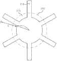
图1是分解透视图,示出了本发明的一个示例性实施例所述的VCM;Figure 1 is an exploded perspective view showing a VCM according to an exemplary embodiment of the present invention;
图2是图1中的VCM的剖视图;Fig. 2 is a sectional view of the VCM in Fig. 1;
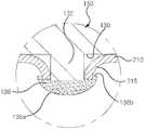
图3是图2中的“A”部的局部放大图;Fig. 3 is a partial enlarged view of part "A" in Fig. 2;
图4是平面图,示出了第一弹性件的通孔的周围;Fig. 4 is a plan view showing the surroundings of the through hole of the first elastic member;
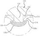
图5是剖视图,示出了本发明的另一个示例性实施例所述的VCM的第一弹性件和凸起;5 is a cross-sectional view showing a first elastic member and a protrusion of a VCM according to another exemplary embodiment of the present invention;
图6是剖视图,示出了本发明的又一个示例性实施例所述的VCM的第一弹性件和凸起;6 is a cross-sectional view showing a first elastic member and protrusions of a VCM according to yet another exemplary embodiment of the present invention;
图7是剖视图,示出了本发明的再一个示例性实施例所述的VCM的第一弹性件和凸起;7 is a cross-sectional view showing a first elastic member and protrusions of a VCM according to yet another exemplary embodiment of the present invention;
图8是平面图,示出了本发明的再一个示例性实施例所述的VCM的第一弹性件;8 is a plan view showing a first elastic member of a VCM according to yet another exemplary embodiment of the present invention;
图9是剖视图,示出了图8中的第一弹性件和热熔合的防脱单元;Fig. 9 is a cross-sectional view showing the first elastic member and the thermally fused anti-off unit in Fig. 8;
图10是剖视图,示出了形成有与图8中的第一弹性件和粘合剂接合的凸起的防脱单元;FIG. 10 is a cross-sectional view showing an anti-off unit formed with a protrusion engaged with the first elastic member and adhesive in FIG. 8;
图11是本发明的一个示例性实施例所述的VCM的分解透视图;Figure 11 is an exploded perspective view of a VCM according to an exemplary embodiment of the present invention;
图12是图11所示的VCM的剖视图;Figure 12 is a cross-sectional view of the VCM shown in Figure 11;
图13是俯视图,示出了图11中的线筒的后表面;Fig. 13 is a plan view showing the rear surface of the bobbin in Fig. 11;
图14是俯视图,示出了图11中的第一弹性件;Fig. 14 is a top view, showing the first elastic member in Fig. 11;
图15是剖视图,示出了图11中的线筒和第一弹性件的状态图;Fig. 15 is a cross-sectional view showing a state view of the bobbin and the first elastic member in Fig. 11;
图16是剖视图,示出了本发明的另一个示例性实施例所述的VCM的线筒和第一弹性件的状态;16 is a sectional view showing a state of a bobbin and a first elastic member of a VCM according to another exemplary embodiment of the present invention;
图17是剖视图,示出了本发明的再一个示例性实施例所述的VCM的线筒和第一弹性件的状态;17 is a sectional view showing a state of a bobbin and a first elastic member of a VCM according to still another exemplary embodiment of the present invention;
图18是本发明的一个示例性实施例所述的VCM的分解透视图;Figure 18 is an exploded perspective view of a VCM according to an exemplary embodiment of the present invention;
图19是俯视图,示出了图17中的第一弹性件;Fig. 19 is a top view, showing the first elastic member in Fig. 17;
图20后透视图,示出了图17中的线筒和弹性件中的第一弹性件;Figure 20 is a rear perspective view showing the first elastic member of the wire barrel and elastic members in Figure 17;
图21是图20中的“A”部的局部放大图;Figure 21 is a partial enlarged view of part "A" in Figure 20;
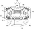
图22是本发明的一个示例性实施例所述的VCM的局部切出部分的透视图;Figure 22 is a perspective view of a partially cut-out portion of a VCM according to an exemplary embodiment of the present invention;
图23是透视图,示出了图22中的线筒和弹性件;Fig. 23 is a perspective view showing the bobbin and elastic member in Fig. 22;
图24是图22中的“A”部的局部放大图;以及Figure 24 is a partial enlarged view of part "A" in Figure 22; and
图25是剖视图,示出了线筒和弹性件结合的过程。Fig. 25 is a sectional view showing the process of combining the bobbin and the elastic member.
具体实施方式Detailed ways
参考附图以及下面的示例性实施例的详细描述可以更容易理解本发明的优点和特征。为简短和清晰起见,公知的功能、配置或构造的详细描述省略,以便不会用不必要的细节模糊了本发明的描述。因此,本发明不限于下面将描述的这些示例性实施例,也可以用其它形式来实现。为方便起见,在附图中,部件的宽度、长度、厚度等可以被夸大或缩小。此外,在整个说明书中,在说明所述图时,相同的附图标记指示相同的元件,并且相同的说明将被省略。因此,说明书和权利要求书中所使用的特殊术语或词汇的含义不应该限于字面上的或通用的意义,而是应该可以根据使用者或操作者的意图以及习惯用法来解释或有所不同。所以,特殊术语或词汇的定义应该基于整个说明书的内容。The advantages and features of the present invention may be more readily understood with reference to the accompanying drawings and the following detailed description of exemplary embodiments. For brevity and clarity, detailed descriptions of well-known functions, configurations or constructions are omitted so as not to obscure the description of the present invention with unnecessary detail. Therefore, the present invention is not limited to these exemplary embodiments to be described below, but may also be implemented in other forms. For convenience, in the drawings, the width, length, thickness, etc. of components may be exaggerated or reduced. In addition, throughout the specification, when describing the drawings, the same reference numerals denote the same elements, and the same description will be omitted. Therefore, the meanings of specific terms or words used in the specification and claims should not be limited to literal or general meanings, but can be interpreted or differed according to user or operator's intention and customary usage. Therefore, the definition of special terms or vocabulary should be based on the contents of the entire specification.
这里,术语“第一”、“第二”等并不表示任何顺序、数量或重要性,而是用来使一个元件与另一个元件区分开来,这里,术语“a”和“an”并不表示数量的限制,而是表示存在至少一个所提及的事项。Here, the terms "first", "second", etc. do not denote any order, quantity or importance, but are used to distinguish one element from another element, where the terms "a" and "an" are not Does not indicate a limitation of number, but rather indicates that there is at least one of the mentioned items.
如这里会使用的,术语“基本上”和“约”提供了所对应的术语的工业上可接受的容差和/或提供了事项之间的相对性。这种工业上可接受的容差落在从小于1%到10%的范围,并且对应着但不限于部件值、角度等。这种事项之间的相对性落在从小于1%到10%的范围内。As will be used herein, the terms "substantially" and "about" provide an industry-accepted tolerance of the corresponding term and/or provide a relativity between the items. Such industry-accepted tolerances range from less than 1% to 10%, and correspond to, but are not limited to, component values, angles, and the like. The relativity between such matters falls within the range from less than 1% to 10%.
图1是分解透视图,示出了本发明的一个示例性实施例所述的VCM,图2是图1中的VCM的剖视图。FIG. 1 is an exploded perspective view showing a VCM according to an exemplary embodiment of the present invention, and FIG. 2 is a cross-sectional view of the VCM in FIG. 1 .
参看图1和图2,VCM 800包括转子100、弹性件200、定子300、外壳400和基座600。转子100包括线筒150和线圈部件190。Referring to FIGS. 1 and 2 , the
线筒150具有例如中空成孔圆筒的形状,用于在其中容纳镜头。圆筒状线筒150包括上表面120以及与上表面120相对的下表面130。The
用于容纳镜头的线筒150的内表面形成有内螺纹单元,镜头固定件(未示出)与该内螺纹单元接合,并且该镜头固定件与所述镜头接合。或者,也应该意识到,所述镜头与线筒150上的内螺纹单元直接接合。The inner surface of the
线筒150的外周下端形成有用于支撑线圈部件190(后面描述)的台阶115。The outer peripheral lower end of the
转子100中的线圈部件190被布置于形成在线筒150上的系挂台(hitchingsill)115上,并且呈例如绕有线圈的圆筒的形状。线圈部件190可以直接绕在线筒150的周围,也可以在绕成圆筒状之后通过粘合剂附着在线筒150的周围。The
定子300包括轭310和磁体350。轭310包括上板312、侧板314和轭单元316。轭310的上板312在俯视时可以呈方板形状,并且中央形成有圆形开口以露出线筒150的上末端。The
侧板314从上板312的四个边缘沿着与线筒150的外周平行的方向延伸,并且与上板312的四个边缘一体形成。轭单元316从上板312的圆形开口所形成的上板312的内侧面朝着面向线筒下末端的方向延伸。轭单元316插在线筒150和线圈部件190所形成的空间中。The
磁体350被布置在轭310的上板312和侧板314所形成的内部空间中。每个磁体350被布置在与轭310的轭单元316的位置相对应的位置处,并且每个磁体350面对线圈部件190。The
线筒150在磁体350所形成的磁场和线圈部件190所形成的磁场所产生的力的作用下向上移动,并且线筒150由第一弹性件210和第二弹性件220进行弹性支撑。此时,线筒150的移动距离可以通过施加在线圈部件190上的电流来精确地调节。The
外壳400包括上壳410和下壳420。上壳410包括上板411和接合柱412。上壳410被布置在轭310的上表面,并且所述弹性件400中的第二弹性件220(后面将描述)插在上壳410和轭310之间。The
俯视时,上壳410的上板411呈方形板的形状,并且在中央形成有圆形开口414以露出线筒150。When viewed from above, the
接合柱412从上板411的四个角落平行于线筒150而突出,并且与下壳420(后面描述)接合。下壳420包括与上壳410的每个接合柱412接合的柱425。Engagement posts 412 protrude from four corners of the
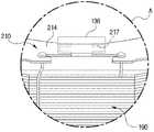
图3是图2中的“A”部的局部放大图,而图4是平面图,示出了第一弹性件的通孔的周围。FIG. 3 is a partial enlarged view of portion 'A' in FIG. 2, and FIG. 4 is a plan view showing the surroundings of the through hole of the first elastic member.
参看图1、图3和图4,本发明的本示例性实施例中的弹性件200包括第一弹性件210和第二弹性件220。第一弹性件210和第二弹性件220可以是例如片簧,每个片簧的厚度都较薄。Referring to FIG. 1 , FIG. 3 and FIG. 4 , the
第一弹性件210与线筒150的下表面130接合。第一弹性件210包括例如两个部分,并且每个第一弹性件210都形成有通孔212,用于与形成在线筒150的下表面130的凸起132接合。第一弹性件210通过通孔212与凸起132接合,而凸起132则形成有防脱单元134,用于防止与凸起132接合的第一弹性件210脱离到凸起132的外部。The first
防脱单元134形成在凸起132的上末端,呈圆头形状,并通过在凸起132的末端进行热压而形成。防脱单元134包括圆头形弯曲单元134a和与线筒150的下表面130相对的平面单元134b(或平面)。在线筒150的下表面130和平面单元134b之间形成间隙G。The
在本发明的示例性实施例中,如果形成在线筒150的下表面130与平面单元134b之间的间隙G基本上与第一弹性件210的厚度相同,那么第一弹性件210不会从线筒150的下表面130脱离,而是会紧紧地与线筒150的下表面130接触。In an exemplary embodiment of the present invention, if the gap G formed between the
形成在线筒150的下表面130与防脱单元134的平面134b之间的间隙G由于各种原因形成为大于第一弹性件210的厚度,这些原因包括在制造尺寸非常小的凸起132的过程中所产生的制造公差,或者在尺寸非常小的凸起132上形成防脱单元134的过程中所产生的制造公差。The gap G formed between the
如果形成在线筒150的下表面130与防脱单元134的平面单元134b之间的间隙G形成为大于第一弹性件210的厚度,那么,第一弹性件210就在线筒150的下表面130与平面单元134b之间移动。如果第一弹性件210在线筒150的下表面130与平面134b之间移动,那么,由VCM 800调节图像传感器和镜头之间的距离的性能就大大地降低了。If the gap G formed between the
在本发明的示例性实施例中,即使线筒150的下表面130与防脱单元134的平面单元134b之间形成的间隙G形成为大于第一弹性件210的厚度,第一弹性件210也可以与线筒150的下表面130进行紧密的接触。In an exemplary embodiment of the present invention, even if the gap G formed between the
第一弹性件210形成有多个与通孔212相连的切出单元(cut-out units)214,以便利用第一弹性件210上的通孔212将第一弹性件210与形成在线筒150的下表面130上的凸起132接合。The first
在本发明的示例性实施例中,通孔212的直径小于凸起132的直径,而凸起132的直径形成为小于切出单元214的长度L与通孔212的半径r加起来的和。In an exemplary embodiment of the present invention, the diameter of the through
所述多个切出单元214在第一弹性件210上绕着第一弹性件210的通孔212呈辐射状形成。在下文中,第一弹性件210的形成在一对相邻切出单元214之间的部分被定义为接合单元215。The plurality of
通过将凸起132插入形成有切出单元214的第一弹性件210上的通孔212中,由切出单元214形成的接合单元215产生弹性变形,从而与凸起132的周边接合。在凸起132与第一弹性件210接合起来之后,通过在凸起132的上端进行热压从而在凸起132的上端形成防脱单元134,将第一弹性件210上的接合单元215固定在凸起132和防脱单元134的平面134b相汇的角落区域。于是,第一弹性件210就通过第一弹性件210上的接合单元215紧紧地与线筒150的下表面130接触。By inserting the
图5是剖视图,示出了本发明的另一个示例性实施例所述的VCM的第一弹性件和凸起。5 is a cross-sectional view illustrating a first elastic member and a protrusion of a VCM according to another exemplary embodiment of the present invention.
除了所述防脱单元和所述第一弹性件之外,本发明的该示例性实施例所述的VCM与图1到图4所示的VCM具有基本上相同的配置,因此将省略重复的说明,并且在这些图的说明中,相同的附图标记表示相同的部件。The VCM described in this exemplary embodiment of the present invention has substantially the same configuration as the VCM shown in FIGS. Description, and in the description of these figures, the same reference numerals denote the same components.
参看图4和图5,通过将凸起132插入形成有切出单元214的第一弹性件210上的通孔212中,由切出单元214形成的接合单元215产生弹性变形,从而与凸起132的周边接合。Referring to FIGS. 4 and 5 , by inserting the
当接合单元215与凸起132的周边接合并且在凸起132的上端进行热压时,凸起132的上端就形成有防脱单元134,该防脱单元134的面积比凸起132的面积大。When the
在本发明的所述示例性实施例中,与凸起132的周边接合的接合单元215的末端插入防脱单元134中预定的深度,由此,第一弹性件210就牢牢地固定在防脱单元134的内部。In the exemplary embodiment of the present invention, the end of the engaging
当第一弹性件210上的接合单元215固定地插入防脱单元134中时,防止了第一弹性件210脱离线筒150的下表面,从而精确地控制线筒150的移动距离。When the engaging
图6是剖视图,示出了本发明的又一个示例性实施例所述的VCM的第一弹性件和凸起。6 is a cross-sectional view illustrating a first elastic member and a protrusion of a VCM according to still another exemplary embodiment of the present invention.
除了所述防脱单元和所述第一弹性件之外,本发明的该示例性实施例所述的VCM与图1到图4所示的VCM具有基本上相同的配置,因此将省略重复的说明,并且在这些图的说明中,相同的附图标记表示相同的部件。The VCM described in this exemplary embodiment of the present invention has substantially the same configuration as the VCM shown in FIGS. Description, and in the description of these figures, the same reference numerals denote the same components.
参看图4和图6,当线筒150上的圆柱形凸起132插入形成有切出单元214的第一弹性件210上的通孔212中时,由切出单元214形成的接合单元215产生弹性变形,从而与凸起132的周边接合。接合单元215以相对于第一弹性件210弯曲的形状插入线筒150上的凸起132中。Referring to FIGS. 4 and 6, when the
在接合单元215与凸起132的周边接合之后,在凸起132的上端涂覆粘合剂,并通过紫外线的热量对该粘合剂进行固化,以便在凸起132的上端形成面积比凸起132的面积大的防脱单元136。在本发明的该示例性实施例中,形成防脱单元136的粘合剂可以包括通过紫外线进行固化的紫外线固化粘合剂,或者通过热进行固化的可热固化的粘合剂。After the
由所述粘合剂形成的防脱单元136包括圆头弯曲单元136a、以及与弯曲单元136a相连的平面单元136b,并且第一弹性件210的接合单元215被布置在防脱单元136的平面单元136b和凸起132的周边相汇的地方。The
当第一弹性件210上的接合单元215固定在防脱单元136的平面单元136b和凸起132的周边相汇的地方时,防止了第一弹性件210脱离线筒150的下表面,从而精确地控制线筒150的移动距离。When the
图7是剖视图,示出了本发明的再一个示例性实施例所述的VCM的第一弹性件和凸起。7 is a cross-sectional view illustrating a first elastic member and a protrusion of a VCM according to still another exemplary embodiment of the present invention.
除了所述防脱单元和所述第一弹性件之外,本发明的该示例性实施例所述的VCM与图6所示的VCM具有基本上相同的配置,因此将省略重复的说明,并且在这些图的说明中,相同的附图标记表示相同的部件。The VCM according to this exemplary embodiment of the present invention has substantially the same configuration as the VCM shown in FIG. 6 except for the anti-off unit and the first elastic member, so repeated description will be omitted, and In the description of these figures, the same reference numerals denote the same components.
参看图4和图7,当线筒150上的圆柱形凸起132插入形成有切出单元214的第一弹性件210上的通孔212中时,由切出单元214形成的接合单元215产生弹性变形,从而与凸起132的周边接合。接合单元215以相对于第一弹性件210弯曲的形状插入线筒150上的凸起132中。Referring to FIGS. 4 and 7, when the
在接合单元215与凸起132的周边接合之后,在凸起132的上端涂覆粘合剂,并通过紫外线的热量对该粘合剂进行固化,以便在凸起132的上端形成面积比凸起132的面积大的防脱单元136。在本发明的该示例性实施例中,形成防脱单元136的粘合剂可以包括通过紫外线进行固化的紫外线固化粘合剂,或者通过热进行固化的可热固化的粘合剂。After the
由所述粘合剂形成的防脱单元136包括圆头弯曲单元136a、以及与弯曲单元136a相连的平面单元136b,并且第一弹性件210的接合单元215的至少一部分插在防脱单元136中。更具体地说,当未固化过的粘合剂覆盖在凸起132上或粘合剂正在进行固化时,第一弹性件210上的接合单元215插在防脱单元136中。The
当第一弹性件210上的接合单元215插在防脱单元136中时,防止了第一弹性件210脱离线筒150的下表面130,从而精确地控制安装有镜头的线筒150的移动距离。When the
图8是平面图,示出了本发明的又一个示例性实施例所述的VCM的第一弹性件。图9是剖视图,示出了图8中的第一弹性件和热熔合的防脱单元,而图10是剖视图,示出了形成有与图8中的第一弹性件和粘合剂接合的凸起的防脱单元。FIG. 8 is a plan view showing a first elastic member of a VCM according to still another exemplary embodiment of the present invention. Fig. 9 is a cross-sectional view showing the first elastic member and the thermally fused anti-off unit in Fig. 8, and Fig. 10 is a cross-sectional view showing a joint formed with the first elastic member and adhesive in Fig. 8 Raised anti-break unit.
除了所述第一弹性件之外,本发明的所述又一个示例性实施例所述的VCM与图1到图6所示的VCM具有基本上相同的配置,因此将省略重复的说明,并且在这些图的说明中,相同的附图标记表示相同的部件。Except for the first elastic member, the VCM according to the still another exemplary embodiment of the present invention has substantially the same configuration as the VCM shown in FIGS. 1 to 6 , so repeated description will be omitted, and In the description of these figures, the same reference numerals denote the same components.
参看图8、图9和图10,第一弹性件210包括通孔212,该通孔212与形成在线筒150的下表面130的凸起132接合。在本发明的该示例性实施例中,通孔212的直径形成为大于凸起132的直径,因此,在由通孔212形成的第一弹性件210的内侧面212a与凸起132的周边之间形成了一个空间。Referring to FIGS. 8 , 9 and 10 , the first
多个接合单元216以预定的间隔从通孔212所形成的第一弹性件210的内侧面212a突出,每个接合单元216的长度形成为长于通孔212的直径与凸起132的直径之差。于是,当凸起132与通孔212接合时,凸起132的周边就被弹性地布置有多个接合单元216,每个接合单元216从第一弹性件210的内侧面212a突出。A plurality of
参看图9,当形成在第一弹性件210上的接合单元216被布置在凸起132的周边之后,通过热压使凸起132的上端变形,以便在凸起132上形成防脱单元134,并且将第一弹性件210的接合单元216布置在防脱单元134的平面单元134b和凸起132的周边相汇之处,从而使第一弹性件210与线筒150的下表面130紧密地接触。或者,当在凸起132上形成防脱单元134时,可以将第一弹性件210的接合单元216的一部分插入防脱单元134中。Referring to FIG. 9, after the engaging
同时,如图10所示,当形成在第一弹性件210上的接合单元216被布置在凸起132的周边之后,用粘合剂涂覆凸起132的上端,并且通过紫外线的热量对该粘合剂进行固化,以便在凸起132上形成防脱单元136,并且将第一弹性件210的接合单元216布置在防脱单元136的平面单元136b和凸起132的周边相汇之处。或者,当在凸起132上形成防脱单元136时,可以将第一弹性件210的接合单元216的一部分插入防脱单元136中。Meanwhile, as shown in FIG. 10, after the
再参看图1,第二弹性件220与线筒150的上表面120接合,并且安装有线圈部件19的线筒150由第一弹性件210和第二弹性件220弹性地支撑。Referring again to FIG. 1 , the second
从前面的描述可以清楚看到,通过形成在线筒和弹性地支撑线筒的弹性件之间的间隙,可以防止弹性件脱离线筒,从而精确地控制安装在线筒上的镜头与图像传感器之间的距离。As is clear from the foregoing description, by forming a gap between the bobbin and the elastic member elastically supporting the bobbin, the elastic member can be prevented from coming off the bobbin, thereby precisely controlling the gap between the lens mounted on the bobbin and the image sensor. distance.
图11是本发明的一个示例性实施例所述的VCM的分解透视图,图12是图11所示的VCM的剖视图,图13是俯视图,示出了图11中的线筒的后表面,图14是俯视图,示出了图11中的第一弹性件,以及图15是剖视图,示出了图11中的线筒和第一弹性件的状态图。11 is an exploded perspective view of a VCM according to an exemplary embodiment of the present invention, FIG. 12 is a cross-sectional view of the VCM shown in FIG. 11 , and FIG. 13 is a plan view showing the rear surface of the bobbin in FIG. 11 , FIG. 14 is a top view showing the first elastic member in FIG. 11 , and FIG. 15 is a cross-sectional view showing a state of the bobbin and the first elastic member in FIG. 11 .
参看图11到图15,VCM 800包括转子100、弹性件200、定子300、弹性件210、强化件500(见图15)以及外壳400。VCM 800还可以包括基板600和隔离件700。转子100包括线筒150和线圈部件190。11 to 15, the
参看图12和图13,线筒150包括线筒体110、接合凸起120和凹槽130。线筒体110具有例如中空成孔圆筒的形状,用于在其中容纳镜头。圆筒状线筒体110包括上表面116以及与上表面116相对的下表面117。Referring to FIGS. 12 and 13 , the
用于容纳镜头的线筒体110的内表面形成有内螺纹单元112,镜头固定件(未示出)与该内螺纹单元112接合,并且该镜头固定件与所述镜头接合。或者,也应该意识到,所述镜头与线筒体110上的内螺纹单元112直接接合。The inner surface of the
线筒体110的周边的下末端形成有系挂台115,用于支撑线圈部件190(后面描述)。A lower end of the periphery of the
参看图13,接合凸起120从线筒体110的下表面117突起,以固定弹性件200中的第一弹性件210(后面描述)。四个接合凸起120形成在线筒体110的四个角落,各个接合凸起120在线筒体110的下表面上等距离形成,以便与第一弹性件210稳定地接合。Referring to FIG. 13 , the
参看图15,在第一弹性件210与线筒150的下表面117接合之后,对每个接合凸起120的末端进行热熔合,以防止第一弹性件210与线筒150脱离,由此,接合凸起120的末端形成有头单元123,头单元123比原始的接合凸起120的尺寸要大。Referring to FIG. 15, after the first
再参看图13,在线筒体110的下表面上邻近每个接合凸起120形成凹槽130,并且第一弹性件210(后面描述)与接合凸起120一道固定到线筒150的下表面。Referring again to FIG. 13 , a
在本发明的该示例性实施例中,凹槽130邻近第一弹性件210(后面描述)的末端而形成。凹槽130邻近第一弹性件210的末端而形成的原因是,当线筒150垂直工作时,在第一弹性件210上作用有使第一弹性件210脱离线筒体150的力。In this exemplary embodiment of the present invention, the
线圈部件190被布置于形成在线筒150上的系挂台115上,并且呈例如绕有线圈的圆筒的形状。线圈部件190可以固定在线筒150的系挂台115上和/或利用粘合剂固定到线筒150的周围,形成线圈部件190的线圈与片簧200(后面描述)的第一弹性件210电连接。The
再参看图11和12,定子300包括轭310和磁体350。轭310包括上板312、侧板314和轭单元316。轭310用来防止磁体350(后面描述)所产生的磁通量泄漏到轭310的外部。Referring again to FIGS. 11 and 12 , the
轭310的上板312在俯视时可以呈方板形状,并且中央形成有圆形开口以露出线筒150的上末端。The
侧板314从上板312的四个边缘沿着与线筒150的外周平行的方向延伸,并且与上板312的四个边缘一体形成。轭单元316从上板312的圆形开口所形成的上板312的内侧面朝着面向线筒150下末端的方向突出,其中,轭单元316与侧板314相互平行布置。轭单元316插在线筒150和线圈部件190所形成的空间中。轭单元316通过使线圈部件190所产生的磁通量面对磁体350进一步增强转子100的驱动效率。The
磁体350被布置在轭310的上板312和侧板314所形成的内空间中。每个磁体350被布置为与线圈部件190相对。The
线筒150在磁体350所形成的磁场和线圈部件190所形成的磁场所产生的力的作用下向上移动,并且该移动的线筒150由弹性件200(后面描述)进行弹性支撑。此时,线筒150的移动距离可以通过施加在线圈部件190上的电流来精确地调节。The
再参看图11、图12和图14,弹性件200包括第一弹性件210和第二弹性件220。第一弹性件210与线筒150的下表面117弹性地接合,第二弹性件220与线筒150的上表面116弹性地接合。Referring to FIG. 11 , FIG. 12 and FIG. 14 again, the
可以形成例如两个第一弹性件210,各个第一弹性件210对称地形成,以与线筒150的下表面117接合。同时,可以形成例如一个第二弹性件220。For example, two first
两个第一弹性件210中的每个都通过对厚度较薄的金属板进行处理来形成,并且具有导电性的两个第一弹性件210与线圈部件190上的线圈电连接。Each of the two first
从外界将驱动信号提供给线圈部件190(通过两个第一弹性件210),线圈部件190产生磁场。A driving signal is supplied from the outside to the coil part 190 (through the two first elastic members 210), and the
参看图13和图14,每个第一弹性件210包括外片簧单元211、内片簧单元213以及将外片簧单元211与内片簧单元213弹性地连接起来的连接弹簧215。Referring to FIGS. 13 and 14 , each first
第一弹性件210的内片簧单元213的两个末端都形成有第一通孔216和第二通孔217。第一通孔216形成在内片簧单元213的两个末端,与线筒150上的接合凸起120相对并插入线筒150的接合凸起120。Both ends of the inner
如果内片簧单元213的第一通孔216插入了线筒150的接合凸起120,那么,内片簧单元213就被布置在线筒150的下表面117上。在内片簧单元213的第一通孔216插入了线筒150的接合凸起120并且对接合凸起120施加热压之后,接合凸起120的末端就通过热熔合过程形成尺寸比第一通孔216的尺寸大的头单元,并熔合到内片簧单元213中。If the first through
第二通孔217形成在内片簧单元213的两个末端,与线筒150上的凹槽130相对以便将凹槽130露在第一弹性件210之外。Second through
在本发明的该示例性实施例中,在第一弹性件210上的第一通孔216与线筒150上的接合凸起120接合之后,第一弹性件210上的第二通孔217和形成在线筒150的下表面117上与第二通孔217相对应的凹槽130用来使第一弹性件210和线筒150相互接合。In this exemplary embodiment of the present invention, after the first through
再参看图15,强化件500被布置在第一弹性件210的第二通孔217和线筒150的凹槽130上,以便同接合凸起120和第一通孔216一起强化线筒150和第一弹性件210之间的接合强度,由此可以使VCM 800的耐用性增强。15, the reinforcing
本发明的该示例性实施例所述的强化件500包括粘合剂,并且如果通过第二通孔217向线筒150上的凹槽130注入液体粘合剂,则该液体粘合剂通过毛细现象填满线筒150的凹槽130和第二通孔217所形成的空间,并且如图5所示,该液体粘合剂通过毛细现象扩展到第一弹性件210和线筒150的下表面117之间的间隙中,从而大大地增加了第一弹性件210和线筒150的下表面117之间的接触面积。The reinforcing
如果液体粘合剂被填入第二通孔217和线筒150上的凹槽130中,那么,对该粘合剂进行固化,以形成将线筒150上的凹槽130和第二通孔217连接起来的强化件500。在本发明的该示例性实施例中,所述粘合剂可以包括可热固化的粘合剂。If the liquid adhesive is filled in the second through
再参看图11和图12,外壳400包括上壳410和下壳420。上壳410包括上板411和接合柱412。上壳410被布置在轭310的上表面,并且片簧200中的第二弹性件220插在上壳410的上板411和轭310之间。Referring to FIG. 11 and FIG. 12 again, the
俯视时,上壳410的上板411呈方形板的形状,并且在中央形成有圆形开口414以露出线筒150。When viewed from above, the
接合柱412从上板411的四个角落平行于线筒150而突出,并且与下壳420(后面描述)接合。下壳420包括底板421和接合柱425。底板421呈板的形状,并且在中央形成圆形开口422。Engagement posts 412 protrude from four corners of the
底板421形成有与上壳410的每个接合柱412接合的柱425。上壳410的接合柱412和下壳420的接合柱421可以通过例如半搭接方法(half lap-jointmethod)进行接合。The
在下壳420的底板421上布置与线筒150的下表面117接合的第一弹性件210的外片簧单元211。在第一弹性件210的外片簧单元211的上表面上布置方框形隔离件700,从而使第一弹性件210的外片簧单元211插在下壳410的底板421和隔离件700之间。The outer
图16是剖视图,示出了本发明的另一个示例性实施例所述的VCM的线筒和第一弹性件的状态。16 is a cross-sectional view illustrating a state of a bobbin and a first elastic member of a VCM according to another exemplary embodiment of the present invention.
除了所述强化件之外,本发明的所述另一个示例性实施例所述的VCM与图15所示的VCM具有基本上相同的配置,因此将省略重复的说明,并且在这些图的说明中,相同的附图标记表示相同的部件。Except for the reinforcing member, the VCM according to the other exemplary embodiment of the present invention has substantially the same configuration as the VCM shown in FIG. In , the same reference numerals denote the same components.
参看图16,VCM 800的强化件500通过第一弹性件210上的第二通孔217插入线筒150上的凹槽130中,以便同接合凸起120一起强化线筒150和第一弹性件210之间的接合强度,由此可以增强VCM 800的耐用性。Referring to FIG. 16 , the reinforcing
根据本发明的该另一示例性实施例所述的强化件500包括螺丝体510以及包括头单元520的紧固件。螺丝体510的周边形成有螺纹,并螺接到线筒150的凹槽130所形成的内侧面上。The reinforcing
头单元520形成为尺寸上大于第二接合孔217,并且如果螺丝体510与线筒150的凹槽130接合,那么头单元520就与对着下壳420的第一弹性件210的下表面接触,从而防止第一弹性件210脱离线筒150。The
图17是剖视图,示出了本发明的再一个示例性实施例所述的VCM的线筒和第一弹性件的状态。17 is a cross-sectional view showing a state of a bobbin and a first elastic member of a VCM according to still another exemplary embodiment of the present invention.
除了所述强化件之外,本发明的所述再一个示例性实施例所述的VCM与图15所示的VCM具有基本上相同的配置,因此将省略重复的说明,并且在这些图的说明中,相同的附图标记表示相同的部件。The VCM according to the still another exemplary embodiment of the present invention has substantially the same configuration as the VCM shown in FIG. In , the same reference numerals denote the same components.
参看图17,VCM 800的强化件500通过第一弹性件210上的第二通孔217插入线筒150上的凹槽130中,以便同接合凸起120一起强化线筒150和第一弹性件210之间的接合强度,由此可以增强VCM 800的耐用性。Referring to FIG. 17 , the reinforcing
根据本发明的该另一示例性实施例所述的强化件500包括体部510以及包括头单元520的接合钉。体部510被压合到线筒150的凹槽130中。头单元520形成为尺寸上大于第二接合孔217,并且如果体部510与线筒150的凹槽130接合,那么头单元520就与对着下壳420的第一弹性件210的下表面接触,从而防止第一弹性件210脱离线筒150。The reinforcing
从前面的描述可以清楚看到,本发明所述的VCM的有益效果是,所述线筒的底端形成有接合凸起和凹槽,在与所述线筒的底端接合的第一弹性件上,第一通孔形成为与所述接合凸起相对并插入所述接合凸起,在所述第一弹性件上,第二通孔形成为与所述凹槽相对,所述接合件的末端被热熔合,以及所述第二接合孔和所述凹槽填充有强化件以增强所述线筒与所述第一弹性件之间的接合强度,由此防止所述第一弹性件脱落,从而增加了耐用性并降低了制造成本。It can be clearly seen from the foregoing description that the beneficial effect of the VCM of the present invention is that the bottom end of the wire barrel is formed with engaging protrusions and grooves, and the first elastic body engaged with the bottom end of the wire barrel On the first elastic member, a first through hole is formed opposite to the engaging protrusion and inserted into the engaging protrusion, on the first elastic member, a second through hole is formed opposite to the groove, and the engaging member is thermally fused, and the second joint hole and the groove are filled with reinforcements to enhance the joint strength between the bobbin and the first elastic member, thereby preventing the first elastic member from shedding, which increases durability and reduces manufacturing costs.
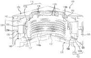
图18是本发明的一个示例性实施例所述的VCM的分解透视图,图19是俯视图,示出了图17中的第一弹性件,图20是后透视图,示出了图17中的线筒和弹性件中的第一弹性件,而图21是图20中的“A”部的局部放大图。Figure 18 is an exploded perspective view of the VCM according to an exemplary embodiment of the present invention, Figure 19 is a top view showing the first elastic member in Figure 17, Figure 20 is a rear perspective view showing the The wire barrel and the first elastic member in the elastic member, and FIG. 21 is a partial enlarged view of part “A” in FIG. 20 .
参看图18,VCM 800包括转子100、弹性件200、定子300。VCM 800还可以包括隔离件700。参看图18和图19,转子100包括线筒150和线圈部件190。Referring to FIG. 18 ,
线筒150可以呈两端开口的圆筒形状。两端开口的圆筒形线筒150用来容纳并固定镜头。在本发明的该示例性实施例中,线筒150可以呈例如两端开口的圆筒形状。The
线筒150的内表面形成有用于容纳镜头的内螺纹单元112,并利用内螺纹112来固定所述镜头。所述镜头可以利用镜头固定件固定到线筒150的内螺纹单元112上。或者,也应该意识到,所述镜头与线筒体110上的内螺纹单元112直接接合。The inner surface of the
线筒体110的周边的下末端形成有系挂台115,用于支撑线圈部件190(后面描述)。A lower end of the periphery of the
参看图20,所述线筒的下表面对称地形成有基于线筒150的凸起132。形成在线筒150的下表面130的凸起132用来使线筒150容纳到外壳400(后面描述)的下壳420(或基座)中。Referring to FIG. 20 , the lower surface of the bobbin is symmetrically formed with
形成在线筒150的下表面130上的凸起132可以呈立方体形状。或者,形成在线筒150的下表面130上的凸起132可以呈立方体形状之外的其它各种形状。形成在线筒150的下表面130上的凸起132的两侧可以形成有柱状接合凸起134。The
接合凸起134与弹性件200(后面描述)中的第一弹性件210接合,用来使弹性件200与线筒150的下表面130紧密地接触。接合凸起134的末端通过热压进行热熔合,从而使第一弹性件210与下表面130紧密接触。The
在线筒150的下表面130上同接合凸起134一起额外地形成有汇合单元136。在本发明的该示例性实施例中,汇合单元136可以呈例如立方柱的形状。或者汇合单元136除了立方柱之外可以呈各种形状,包括圆柱、方形柱以及多边形柱。A
形成在线筒150的下表面130上的汇合单元136形成在相邻一对凸起132的中心。汇合单元136被布置在与所述一对第一弹性件200(后面描述)相对的末端的位置所对应的位置处。汇合单元136用来使弹性件200中的第一弹性件210的末端与线筒150的下表面130紧密接触。A
在本发明的该示例性实施例中,当从线筒150的下表面130起测量汇合单元136的高度时,汇合单元136低于凸起132。In this exemplary embodiment of the present invention, when the height of the merging
如果汇合单元136高于凸起132,那么,当线筒150被放入外壳400中时,汇合单元136会在凸起132之前与下壳420接触,从而使线筒150倾斜。If the merging
线圈部件190被绕在线筒150的周围,并被固定在形成在线筒150的下部周围表面上的系挂台115上。线圈部件190可以固定到线筒150的系挂台115上,和/或使用粘合剂固定到线筒150的周围。线圈部件190可以例如使用粘合剂结合到线筒150的周围。或者,也可以清楚看到,圆筒形缠绕的线圈部件190插入线筒150的周围,并利用粘合剂与线筒150接合。The
当驱动信号被施加在布置于线筒150的周围的线圈部件190时,产生磁场,线筒150受到线圈部件190所产生的磁场和定子300中的磁体350所产生的磁场驱动。When a driving signal is applied to the
参看图18和图19,弹性件200包括第一弹性件210和第二弹性件220。第一弹性件210与线筒150的下表面130接合,从而弹性地支撑线筒150。Referring to FIG. 18 and FIG. 19 , the
在本发明的该示例性实施例中,第一弹性件210形成一对,并且每个第一弹性件210都与线筒150的下表面130接合,其中,该一对第一弹性件210彼此是电绝缘的。In this exemplary embodiment of the present invention, the first
所述一对第一弹性件210中的每个都形成有连接端211,驱动信号从外部施加到连接端211上。所述一对第一弹性件210中的每个都包括外弹性单元212、内弹性单元214以及连接弹性单元219。Each of the pair of first
外弹性单元212和内弹性单元214通过连接弹性单元219连接起来,并且所述一对第一弹性件210中的每个都利用连接弹性单元219的弹力弹性地支撑线筒150。The outer
外弹性单元212由外壳400(后面描述)中的下壳420和隔离件700固定,内弹性单元214固定到线筒150的下表面130。外弹性单元212形成有连接端211,连接端211与外部电路板电连接。The outer
内弹性单元214使用焊料焊接到构成线圈部件190的线圈的末端。内弹性单元214形成有夹片单元,用来与线圈部件190中的线圈接合。内弹性单元214形成弯板形状,与线筒150的下表面130具有基本上相同的曲率。因此,从外部施加到连接端211的驱动信号就顺序地通过外弹性单元212、内弹性单元214和连接弹性单元219施加到线圈部件190上,从而就从线圈部件190产生了磁场。The inner
内弹性单元214包括通孔215,通孔215形成在图3所示的与形成在线筒150的下表面130的接合凸起134接合的地方。The inner
当一对第一弹性件210沿着线筒150的下表面130布置时,当俯视时,该一对第一弹性件210的内弹性单元的每个末端面对着另一末端。该一对第一弹性件210的内弹性单元的每个末端横过汇合单元136布置,内弹性单元214的每个末端由汇合单元136固定。When the pair of first
如果内弹性单元214的每个末端由汇合单元136固定,那么内弹性单元214的末端就远离线筒150,从而防止线圈部件190中的线圈被内弹性单元214短路,即使VCM 800受到强烈的冲击或振动也是如此。If each end of the inner
参看图20和图21,与第一弹性件210的内弹性单元214面对的每个末端可以形成有凹接合槽217,以便通过汇合单元136将面对第一弹性件210的末端固定到线筒150的下表面130上。Referring to FIG. 20 and FIG. 21 , each end facing the inner
形成在与第一弹性件210的内弹性单元214面对的每个末端的凹接合槽217呈凹槽或开口的形状,插到汇合单元136的表面。The
如果所述汇合单元呈例如立方柱的形状,那么接合槽217可以呈环绕汇合单元136的三个侧面的形状,并且第一弹性件210的内弹性单元214可以通过接合槽217牢固地接合到线筒150的下表面130上。If the confluence unit is in the shape of, for example, a cubic column, the
尽管本发明的示例性实施例说明和示出了形成在线筒150上的所述汇合单元、以及利用该汇合单元汇合第一弹性件210,但所述配置不限于此。例如,面对第一弹性件210的末端可以直接汇合到线筒150的下表面130上,以便防止线圈部件190中的线圈发生短路。Although an exemplary embodiment of the present invention illustrates and illustrates the merging unit formed on the
再参看图18,弹性件200中的第二弹性件220固定到轭310(后面描述)上,并弹性地固定到面对线筒150的下表面130的上表面120上。Referring again to FIG. 18 , the second
定子300包括轭310和磁体350。轭310包括轭上板312、轭侧板314和背轭316。在本发明的该示例性实施例中,轭310用来增强转子100的驱动效率,以便防止磁体350(后面描述)所产生的磁场发生泄漏。The
轭上板312呈矩形板形状,并且中央形成有开口以露出线筒或镜头。轭侧板314从每个边缘朝着环绕线筒150的方向延伸。背轭316从轭上板312的内侧面延伸,以面对轭侧板314的每个角落。The yoke
磁体350被布置在与轭侧板314的每个角落相对的位置,并被布置在与布置在线筒150的周围的线圈部件190相对的位置。磁体350可以例如利用粘合剂粘合到轭侧板314上。The
线筒150在每个磁体350所形成的磁场和线圈部件190所形成的磁场所产生的力的作用下向上移动,并且线筒150由第一弹性件210和第二弹性件220进行弹性支撑。此时,线筒150的移动距离可以通过施加在线圈部件190上的电流来精确地调节。The
外壳400包括上壳410和下壳420。外壳400用来相互接合并固定转子100、弹性件200和定子300。上壳410包括上板411和接合柱412。上壳410被布置在轭310的上表面,弹性件200中的第二弹性件220(后面描述)插在上壳410和轭310之间。The
上壳410中的上板411俯视时呈方板形状,并在中央形成有圆形开口414以露出线筒150。The
上壳410中的接合柱412从上板411的四个角落平行于线筒150突出,并与下壳420(后面描述)接合。下壳420包括与上壳410的每个接合柱412接合的柱425。Engagement posts 412 in the
从前面的描述可以清楚看到,弹性地支撑所述线筒的片簧的末端通过热熔合的方法固定地接合到所述线筒上,以防止所述线圈部件中的线圈从所述片簧发生短路,即使VCM受到强烈的冲击或振动也是如此。As is clear from the foregoing description, the ends of the leaf springs elastically supporting the bobbin are fixedly joined to the bobbin by thermal fusion to prevent the coils in the coil part from being dislodged from the leaf springs. A short circuit occurs even if the VCM is subjected to strong shock or vibration.
图22是本发明的一个示例性实施例所述的VCM的局部切出部分的透视图,图23是透视图,示出了图22中的线筒和弹性件,图24是图22中的“A”部的局部放大图,而图25是剖视图,示出了线筒和弹性件结合的过程。Figure 22 is a perspective view of a partially cut-out portion of a VCM according to an exemplary embodiment of the present invention, Figure 23 is a perspective view showing the bobbins and elastic members in Figure 22, Figure 24 is a perspective view of the VCM in Figure 22 Part "A" is a partially enlarged view, and Fig. 25 is a cross-sectional view showing the process of combining the bobbin and the elastic member.
参看图22到图25,VCM 100可以包括转子110、基座120、定子130、隔离件140和弹性件150、155。所述VCM还可以包括上隔离件160和盖罐170。22 to 25, the
转子100可以包括与镜头(未示出)接合的线筒118和线圈119。转子110用来调节布置在基座120的后表面的图像传感器模块和接合到线筒118上的镜头之间的间隙。The
线筒118可以呈例如圆筒形状,并形成有足以接合盘状镜头的内侧面。线筒118的内侧面形成有螺纹单元,用于接合所述镜头。The
线筒118的外部形成有两个系挂台111、112,形成在下表面的系挂台111被布置有线圈,形成在上表面的系挂台112在其上面布置有定子130(后面描述)的轭的一部分。The outside of the
线筒118中与基座120相对的下表面118a形成有多个凸起117。凸起117用作接合件,与弹性件150(后面描述)接合,线筒118的下表面118a与基座120的上表面通过凸起117而隔开预定的间隙。A plurality of
与线筒118的下表面118a面对的线筒118的上表面118b形成有粘合导耳118c。粘合导耳形成为一对,每个粘合导耳与另一个导耳相邻布置,并且布置在线筒118的上表面118b中邻近线筒118的内侧面处。The
所述一对粘合导耳118c沿着线筒118的上表面118b间歇式地布置,并且可以以相等的间隔形成。The pair of
线圈119通过涂覆有绝缘树脂(诸如珐琅质树脂)的导线来形成并以圆柱形形状绕在线筒118的周围。或者,圆柱形缠绕的线圈119利用粘合剂固定到线筒118的周围。线圈119的下端被布置在系挂台111上。The
圆柱形形成的线圈119的上端被布置在比系挂台112高的位置,由此在线圈119和线筒118的周边之间形成空间。The upper end of the cylindrically formed
基座120可以包括底板123和侧板126。底板123俯视时呈方板的形状,并形成有系挂台121。底板123由系挂台121分成下底板123a和上底板123b。The base 120 may include a
下底板123a在其上布置有线筒118的凸起117,而上底板123b在其上布置有隔离件140。侧板126沿着底板123的边缘形成,并基本上垂直于底板123。The
定子130被布置为与转子110上的线圈119相对,并且用来垂直地移动转子110。定子130包括磁体132和轭138。The
多个磁体132可以绕着线圈119布置,各个磁体相隔等距离间隔。磁体132所产生的磁场和线圈119所产生的磁场产生吸引力和排斥力,在该吸引力和排斥力的作用下,转子110相对于定子130垂直移动。A plurality of
轭138包括外轭单元134、内轭单元135和连结轭单元136。在本发明的该示例性实施例中,轭138包括金属板。轭138防止或限制磁体132所产生的磁场和线圈119所产生的磁场泄漏,由此可以增强转子110的驱动效率。The
外轭单元134包括例如四个板,这四个板形成为平行于线筒118的周边。内轭单元135被布置在与每个磁体132的位置相对应的位置。连结轭单元136的作用是将外轭单元134和内轭单元135相互连接起来。The
磁体132被容纳在轭138中,并且可以利用粘合剂附着在轭138的内部。隔离件140插在磁体132和基座120的底板123的上底板123b之间,从而将磁体132固定在预定的位置。The
上隔离件160压下轭138,从而将轭138置于预定的位置。上隔离件160呈方形,并压下轭138的连结轭单元136,从而将磁体132固定在隔离件140上。The
弹性件150、155弹性地支撑转子110。在下文中,弹性件150、155被定义为第一弹性件150和第二弹性件155。The
包括两个弹性件150的第一弹性件150沿着线筒118的下表面118a布置,并且该两个第一弹性件150之间电连接。第一弹性件150包括内弹性单元、外弹性单元和连接弹性单元。A first
所述内弹性单元呈半圆环的形状,并与形成在线筒118的下表面上的凸起117接合。The inner elastic unit is in the shape of a semi-circular ring, and is engaged with a
所述外弹性单元成半圆环的形状,并插在基座120的底板134的上底板123b与隔离件140之间。所述连接弹性单元弹性地连接所述内弹性单元和所述外弹性单元。在本发明的该示例性实施例中,所述内弹性单元、所述外弹性单元和所述连接弹性单元一体形成。The outer elastic unit is in the shape of a semicircle and is inserted between the
参看图23和图24,第二弹性件155被布置在上表面118b上,该上表面118b是与线筒118的下表面118a面对的末端。第二弹性件155包括内弹性单元156、外弹性单元157和连接弹性单元158。Referring to FIGS. 23 and 24 , the second
内弹性单元156呈圆环的形状,沿着线筒118的上表面118b布置,而外弹性单元157呈圆环的形状,其直径比内弹性单元156的直径大。连接弹性单元158弹性地连接内弹性单元156和外弹性单元157,而包括线筒118的转子110通过外弹性单元157被弹性地支撑到定子130上。The inner
外弹性单元157插在上隔离件160和轭138之间,并被上隔离件160和轭138固定。内弹性单元156被布置在与线筒118的上表面118b相对的位置处。The outer elastic unit 157 is interposed between the
连接弹性单元158在例如四个区域弹性地连接内弹性单元156和外弹性单元157,形成在线筒118的上表面118b的粘合导耳118c形成在连接弹性单元158和内弹性单元156相互连接的区域。The connecting
如果粘合导耳118c形成在连接弹性单元158和内弹性单元156相互连接的区域,那么连接弹性单元158和内弹性单元156相互连接的区域处的粘合剂的粘合强度可以进一步得到增强。If the
再参看图23和图24,环形内弹性单元156形成有开口156a,开口156a形成在与形成在线筒118的上表面118b的粘合导耳118c的位置相对应的位置处。粘合导耳118c插在形成在内弹性单元156上的开口156a中。同时,内弹性单元156的一部分延伸到由粘合导耳118c所形成的空间。Referring again to FIGS. 23 and 24 , the annular inner
形成在内弹性单元156上的开口156a的形状从内弹性单元156的内侧面朝着面对内弹性单元156的周边的方向形成。就是说,形成在内弹性单元156上的开口156a可以呈内侧面敞开的内弹性单元156的形状。或者,形成在内弹性单元156上的开口156a可以呈闭合孔的形状。The shape of the opening 156 a formed on the inner
在本发明的该示例性实施例中,形成在内弹性单元156上的开口156a的区域形成为大于每个粘合导耳118c的区域,由此,在粘合导耳118c的侧面和内弹性单元156上的开口156a所形成的侧面之间形成间隙。所述粘合剂通过所述间隙提供在内弹性单元156和线筒118的上表面118b之间。In this exemplary embodiment of the present invention, the area of the
图25是剖视图,示出了图24中的线筒、第二弹性件和提供粘合剂的分送器。Fig. 25 is a cross-sectional view showing the bobbin, the second elastic member and the dispenser for supplying the adhesive in Fig. 24 .
参看图24和图25,线筒118和内弹性单元156通过使形成在第二弹性件155的内弹性单元156上的开口插入形成在线筒118的上表面118b的粘合导耳118c而相互装配起来。随后,分送器10提供粘合剂20到形成为一对的粘合导耳118c之间,粘合剂20通过形成在内弹性单元156上的开口156a和粘合导耳118c之间的间隙被提供在线筒118的上表面118b和内弹性单元156之间。24 and 25, the
如果分送器10提供预定量的粘合剂到粘合导耳118c之间,并与粘合导耳118c分开,那么,粘合剂20就处于被填在面对粘合导耳118c的两个侧壁之间的状态中,从而内弹性单元156不会随着分送器10而分开,即使分送器10与粘合导耳118c分开也是如此,由此可以防止第二弹性件155的内弹性单元156发生变形或损坏。If the
尽管本发明的所述示例性实施例说明并示出了线筒118的上表面118b与第二弹性件155通过使用粘合导耳118c而相互粘合在一起,但配置不限于此。例如,线筒118的上表面118b和第一弹性件150可以通过使用粘合导耳而相互粘合在一起。Although the exemplary embodiment of the present invention illustrates and shows that the
从前面所述可以清楚看到,本发明所述的VCM的有益效果和工业实用性在于,粘合导耳形成在与所述弹性件接合的线筒上,从而防止了所述弹性件发生变形和/或损坏。As can be clearly seen from the foregoing, the beneficial effect and industrial applicability of the VCM of the present invention is that the adhesive lug is formed on the bobbin engaged with the elastic member, thereby preventing the elastic member from being deformed. and/or damaged.
尽管参考若干说明性实施例描述了实施例,但应该明白,本领域中的技术人员可以构思出许多其它修改和实施例,这些修改和实施例落在本发明的原理的精神和范围内。具体说,在说明书、附图和所附权利要求书的范围内,在主题组合配置的部件和/或布置中可以做出各种变型和修改。Although embodiments have been described with reference to a number of illustrative embodiments thereof, it should be understood that numerous other modifications and embodiments can be devised by those skilled in the art that will fall within the spirit and scope of the principles of this invention. In particular, various variations and modifications may be made in the components and/or arrangements of the subject combination arrangement within the scope of the specification, drawings and appended claims.
Claims (36)
Translated fromChinesePriority Applications (1)
| Application Number | Priority Date | Filing Date | Title |
|---|---|---|---|
| CN201710265065.2ACN107222081B (en) | 2010-07-12 | 2011-07-12 | Voice coil motor |
Applications Claiming Priority (8)
| Application Number | Priority Date | Filing Date | Title |
|---|---|---|---|
| KR1020100067051AKR101703025B1 (en) | 2010-07-12 | 2010-07-12 | Voice coil motor |
| KR10-2010-0067051 | 2010-07-12 | ||
| KR10-2010-0071326 | 2010-07-23 | ||
| KR10-2010-0071635 | 2010-07-23 | ||
| KR1020100071635AKR101706355B1 (en) | 2010-07-23 | 2010-07-23 | Voice coil motor |
| KR1020100071326AKR101705523B1 (en) | 2010-07-23 | 2010-07-23 | Voice coil motor |
| KR1020100102737AKR101743292B1 (en) | 2010-10-21 | 2010-10-21 | Voice coil motor |
| KR10-2010-0102737 | 2010-10-21 |
Related Child Applications (1)
| Application Number | Title | Priority Date | Filing Date |
|---|---|---|---|
| CN201710265065.2ADivisionCN107222081B (en) | 2010-07-12 | 2011-07-12 | Voice coil motor |
Publications (2)
| Publication Number | Publication Date |
|---|---|
| CN102332805Atrue CN102332805A (en) | 2012-01-25 |
| CN102332805B CN102332805B (en) | 2017-05-17 |
Family
ID=45438391
Family Applications (2)
| Application Number | Title | Priority Date | Filing Date |
|---|---|---|---|
| CN201110195036.6AActiveCN102332805B (en) | 2010-07-12 | 2011-07-12 | Voice coil motor |
| CN201710265065.2AActiveCN107222081B (en) | 2010-07-12 | 2011-07-12 | Voice coil motor |
Family Applications After (1)
| Application Number | Title | Priority Date | Filing Date |
|---|---|---|---|
| CN201710265065.2AActiveCN107222081B (en) | 2010-07-12 | 2011-07-12 | Voice coil motor |
Country Status (2)
| Country | Link |
|---|---|
| US (9) | US8810936B2 (en) |
| CN (2) | CN102332805B (en) |
Cited By (15)
| Publication number | Priority date | Publication date | Assignee | Title |
|---|---|---|---|---|
| CN103280941A (en)* | 2012-09-29 | 2013-09-04 | 苏州贝腾特电子科技有限公司 | Micro-driving motor |
| CN103378702A (en)* | 2012-04-20 | 2013-10-30 | 鸿富锦精密工业(深圳)有限公司 | Voice coil motor |
| CN104618629A (en)* | 2013-11-05 | 2015-05-13 | Lg伊诺特有限公司 | Camera module |
| TWI514720B (en)* | 2011-11-01 | 2015-12-21 | Hon Hai Prec Ind Co Ltd | Voice coil motor and camera module using same |
| CN105372784A (en)* | 2014-08-07 | 2016-03-02 | Lg伊诺特有限公司 | Lens moving device and camera module including the lens moving device |
| CN105915019A (en)* | 2016-04-29 | 2016-08-31 | 东莞市东勤电子有限公司 | Voice coil motor and assembly technology thereof |
| CN106300864A (en)* | 2015-05-28 | 2017-01-04 | 鸿富锦精密工业(深圳)有限公司 | Shell fragment and apply the voice coil motor of this shell fragment, electronic installation |
| CN107111101A (en)* | 2014-12-19 | 2017-08-29 | Lg伊诺特有限公司 | lens driver |
| CN107678121A (en)* | 2012-05-09 | 2018-02-09 | Lg伊诺特有限公司 | Voice coil motor |
| CN107873132A (en)* | 2015-07-09 | 2018-04-03 | Lg伊诺特有限公司 | Camera modules and optics |
| CN110365888A (en)* | 2013-11-05 | 2019-10-22 | Lg伊诺特有限公司 | camera module |
| CN111753823A (en)* | 2019-09-10 | 2020-10-09 | 广东小天才科技有限公司 | A method of fixed focus scanning and smart watch |
| CN112492135A (en)* | 2014-12-17 | 2021-03-12 | Lg伊诺特有限公司 | Camera module |
| CN114024411A (en)* | 2014-02-27 | 2022-02-08 | Lg伊诺特有限公司 | Lens driving motor |
| CN115903336A (en)* | 2014-10-17 | 2023-04-04 | Lg伊诺特有限公司 | Lens moving device |
Families Citing this family (42)
| Publication number | Priority date | Publication date | Assignee | Title |
|---|---|---|---|---|
| CN102315748B (en)* | 2010-07-06 | 2015-11-04 | Lg伊诺特有限公司 | Voice coil motor, coil assembly and manufacturing method thereof |
| CN102332805B (en)* | 2010-07-12 | 2017-05-17 | Lg伊诺特有限公司 | Voice coil motor |
| US8836177B2 (en)* | 2010-07-30 | 2014-09-16 | Lg Innotek Co., Ltd. | Voice coil motor |
| US8929005B2 (en) | 2011-11-16 | 2015-01-06 | Lg Innotek Co., Ltd. | Voice coil motor |
| TWI514724B (en)* | 2011-12-27 | 2015-12-21 | Hon Hai Prec Ind Co Ltd | Actuator |
| TWI537627B (en)* | 2011-12-29 | 2016-06-11 | 鴻海精密工業股份有限公司 | Voice coil motor and camera module |
| KR101912385B1 (en) | 2012-05-09 | 2018-12-28 | 엘지이노텍 주식회사 | Voice coil motor |
| KR101958234B1 (en)* | 2012-05-09 | 2019-03-14 | 엘지이노텍 주식회사 | Voice coil motor |
| US9323023B2 (en)* | 2012-08-17 | 2016-04-26 | Tdk Taiwan Corporation | Lens focusing device |
| KR102023720B1 (en) | 2012-09-03 | 2019-09-20 | 엘지이노텍 주식회사 | Voice coil motor |
| US9804354B2 (en)* | 2012-12-26 | 2017-10-31 | Sharp Kabushiki Kaisha | Lens drive apparatus |
| US10528024B2 (en) | 2013-06-17 | 2020-01-07 | Ashley Stone | Self-learning production systems with good and/or bad part variables inspection feedback |
| CA2847995C (en) | 2013-06-17 | 2018-06-05 | Ashley Stone | Molding systems and methods |
| US9389391B2 (en)* | 2013-09-11 | 2016-07-12 | Sunming Technologies (Hk) Limited | Lens driving apparatus and method for manufacturing the same |
| KR102136839B1 (en)* | 2013-11-05 | 2020-07-23 | 엘지이노텍 주식회사 | Camera module |
| KR102209118B1 (en)* | 2013-12-04 | 2021-01-28 | 엘지이노텍 주식회사 | Motor for actuating lens |
| TWI609558B (en)* | 2014-04-14 | 2017-12-21 | 鴻海精密工業股份有限公司 | Voice coil motor |
| WO2015199341A1 (en)* | 2014-06-25 | 2015-12-30 | 엘지이노텍(주) | Lens driving device |
| US9791713B2 (en) | 2014-07-24 | 2017-10-17 | Lg Innotek Co., Ltd. | Lens moving apparatus |
| US10451891B2 (en)* | 2014-10-17 | 2019-10-22 | Lg Innotek Co., Ltd. | Lens moving apparatus |
| CN105591513A (en)* | 2014-10-24 | 2016-05-18 | 鸿富锦精密工业(深圳)有限公司 | Voice coil motor |
| US10531123B2 (en)* | 2015-03-06 | 2020-01-07 | Korea Advanced Institute Of Science And Technology | Image encoding and decoding method based on low-complexity transformation, and apparatus using same |
| KR102311663B1 (en) | 2015-03-18 | 2021-10-13 | 엘지이노텍 주식회사 | A lens moving unit and a camera module including the same |
| US10088645B2 (en)* | 2015-04-03 | 2018-10-02 | Lg Innotek Co., Ltd. | Lens driving device, camera module and optical apparatus |
| CN204481665U (en)* | 2015-04-20 | 2015-07-15 | 新科实业有限公司 | Voice coil motor |
| EP3088931B1 (en) | 2015-04-30 | 2024-09-04 | LG Innotek Co., Ltd. | Lens moving apparatus and camera module and optical device including the same |
| TW201642558A (en)* | 2015-05-28 | 2016-12-01 | 鴻海精密工業股份有限公司 | Shrapnel, voice coil motor and electronic device using the same |
| WO2016206074A1 (en)* | 2015-06-26 | 2016-12-29 | 爱佩仪光电技术(深圳)有限公司 | Anti-magnetic-interference optical anti-vibration voice coil motor and manufacturing method therefor |
| WO2017024584A1 (en)* | 2015-08-13 | 2017-02-16 | 爱佩仪光电技术(深圳)有限公司 | Anti-magnetic-interference translational type optical anti-shake voice coil motor and assembly method therefor |
| CN106772912B (en) | 2015-09-21 | 2021-12-10 | Lg伊诺特有限公司 | Lens driving unit |
| US10042139B2 (en)* | 2015-11-20 | 2018-08-07 | Sae Magnetics (H.K.) Ltd. | Camera lens module |
| CN206489310U (en)* | 2016-09-30 | 2017-09-12 | 扬明光学股份有限公司 | Light path adjusting mechanism |
| US10491923B2 (en)* | 2017-08-14 | 2019-11-26 | Google Llc | Directional deblocking filter |
| JP2021002697A (en)* | 2017-09-05 | 2021-01-07 | アルプスアルパイン株式会社 | Sound production device |
| TWI753615B (en)* | 2017-10-17 | 2022-01-21 | 揚明光學股份有限公司 | Light path adjustment mechanism and fabrication method thereof |
| TWI767947B (en)* | 2017-10-17 | 2022-06-21 | 揚明光學股份有限公司 | Light path adjustment mechanism and fabrication method thereof |
| CN109752810A (en)* | 2017-11-02 | 2019-05-14 | 扬明光学股份有限公司 | Optical path adjustment mechanism and manufacturing method thereof |
| TWI664485B (en)* | 2018-08-07 | 2019-07-01 | 大陽科技股份有限公司 | Camera module and electronic device |
| KR102859287B1 (en) | 2019-04-26 | 2025-09-12 | 엘지이노텍 주식회사 | Camera module and Camera Apparatus including the same |
| US11295769B2 (en)* | 2020-06-29 | 2022-04-05 | Western Digital Technologies, Inc. | Soft mount voice coil motor assembly |
| CN114200620B (en)* | 2020-09-01 | 2025-09-12 | 新思考电机有限公司 | Optical component driving device, camera device, and electronic equipment |
| CN112987448B (en)* | 2021-03-05 | 2022-05-06 | 新思考电机有限公司 | Driving assembly, voice coil motor, camera module and electronic equipment |
Citations (9)
| Publication number | Priority date | Publication date | Assignee | Title |
|---|---|---|---|---|
| CN2874103Y (en)* | 2005-05-12 | 2007-02-28 | 上海环达计算机科技有限公司 | Grabbing type fixing mechanism |
| CN1952719A (en)* | 2005-10-17 | 2007-04-25 | 索尼株式会社 | Lens unit and imaging apparatus |
| CN101178470A (en)* | 2006-11-08 | 2008-05-14 | 日本电产三协株式会社 | Lens driving apparatus and its manufacturing method |
| CN101527490A (en)* | 2009-04-17 | 2009-09-09 | 惠州市百宏微动技术工业有限公司 | Superminiature voice coil motor |
| JP2009210055A (en)* | 2008-03-05 | 2009-09-17 | Mitsumi Electric Co Ltd | Plate spring and lens drive mechanism |
| CN101592771A (en)* | 2008-05-26 | 2009-12-02 | 鸿富锦精密工业(深圳)有限公司 | Voice coil motor actuator |
| KR20100046452A (en)* | 2008-10-27 | 2010-05-07 | 엘지이노텍 주식회사 | Motor for driving lens |
| US20100128372A1 (en)* | 2008-11-27 | 2010-05-27 | Hon Hai Precision Industry Co., Ltd. | Lens actuator |
| CN101750691A (en)* | 2008-12-05 | 2010-06-23 | 百隆光电股份有限公司 | Lens module |
Family Cites Families (37)
| Publication number | Priority date | Publication date | Assignee | Title |
|---|---|---|---|---|
| JP4077497B2 (en)* | 2004-04-13 | 2008-04-16 | 松下電器産業株式会社 | The camera module |
| KR100490253B1 (en) | 2004-10-15 | 2005-05-18 | 주식회사 모비너스 | A device to focus automatically in optical lens |
| US7675566B2 (en)* | 2005-05-24 | 2010-03-09 | Panasonic Corporation | Camera module |
| US7298562B2 (en)* | 2005-09-02 | 2007-11-20 | Nidec Sankyo Corporation | Lens drive unit |
| JP4687972B2 (en) | 2005-10-17 | 2011-05-25 | ソニー株式会社 | Lens unit and imaging device |
| TWI314665B (en)* | 2006-01-12 | 2009-09-11 | Lite On Technology Corp | Digital camera module |
| KR100862303B1 (en) | 2006-05-11 | 2008-10-13 | 엘지이노텍 주식회사 | Lens drive motor |
| KR20080068774A (en)* | 2007-01-20 | 2008-07-24 | 엘지이노텍 주식회사 | Lens drive motor |
| JP2008197311A (en) | 2007-02-13 | 2008-08-28 | Alps Electric Co Ltd | Lens drive device |
| GB0702835D0 (en) | 2007-02-14 | 2007-03-28 | Johnson Electric Sa | Lens module |
| KR101091919B1 (en) | 2007-03-09 | 2011-12-08 | 삼성테크윈 주식회사 | voice coil module |
| JP2008268404A (en)* | 2007-04-18 | 2008-11-06 | Tricore Corp | Voice coil type lens drive device |
| JP2008268474A (en)* | 2007-04-19 | 2008-11-06 | Tricore Corp | Voice coil type lens drive device |
| JP2008268475A (en)* | 2007-04-19 | 2008-11-06 | Tricore Corp | Voice coil type lens driving device |
| KR20080099567A (en) | 2007-05-10 | 2008-11-13 | 주식회사 하이소닉 | Small camera |
| JP2008058946A (en)* | 2007-06-13 | 2008-03-13 | Tricore Corp | VOICE COIL MOTOR TYPE mp FOCUSING ACTUATOR |
| CN101068091B (en)* | 2007-06-13 | 2010-09-01 | 宜兴市贵鑫磁电高科技有限公司 | Ultrasmall type voice coil motor |
| JP4413956B2 (en)* | 2007-08-21 | 2010-02-10 | 新光電気工業株式会社 | Camera module and portable terminal |
| KR101427752B1 (en) | 2007-09-10 | 2014-08-07 | 엘지이노텍 주식회사 | Motor for driving lens |
| JP2009080217A (en) | 2007-09-26 | 2009-04-16 | Shicoh Engineering Co Ltd | Lens driving device, camera and mobil phone with camera |
| JP2009139941A (en) | 2007-11-14 | 2009-06-25 | Nidec Sankyo Corp | Lens drive device, and spring member bonding method |
| JP5218740B2 (en)* | 2008-02-28 | 2013-06-26 | ミツミ電機株式会社 | Lens drive device |
| TWI384319B (en)* | 2008-11-26 | 2013-02-01 | Skina Optical Co Ltd | Lens module |
| WO2010095853A2 (en)* | 2009-02-17 | 2010-08-26 | Lg Innotek Co., Ltd. | Motor for driving lens |
| KR101663830B1 (en)* | 2009-09-15 | 2016-10-10 | 엘지이노텍 주식회사 | Voice coil motor and assembly method of the same |
| KR101081630B1 (en)* | 2009-11-20 | 2011-11-09 | 엘지이노텍 주식회사 | Voice coil motor |
| JP2011169443A (en)* | 2010-02-22 | 2011-09-01 | Mitsumi Electric Co Ltd | Plate spring and lens driving device |
| JP2011169446A (en)* | 2010-02-22 | 2011-09-01 | Mitsumi Electric Co Ltd | Plate spring and lens driving device |
| JP5440796B2 (en)* | 2010-06-16 | 2014-03-12 | ミツミ電機株式会社 | Lens drive device |
| CN102315748B (en)* | 2010-07-06 | 2015-11-04 | Lg伊诺特有限公司 | Voice coil motor, coil assembly and manufacturing method thereof |
| CN102332805B (en)* | 2010-07-12 | 2017-05-17 | Lg伊诺特有限公司 | Voice coil motor |
| KR101741817B1 (en)* | 2010-07-19 | 2017-05-31 | 엘지이노텍 주식회사 | Voice coil motor |
| US8836177B2 (en)* | 2010-07-30 | 2014-09-16 | Lg Innotek Co., Ltd. | Voice coil motor |
| US8912690B2 (en)* | 2010-12-13 | 2014-12-16 | Lg Innotek Co., Ltd. | Voice coil motor |
| US9035502B2 (en)* | 2011-02-07 | 2015-05-19 | Lg Innotek Co., Ltd. | Multifunctional voice coil motor |
| US8929005B2 (en)* | 2011-11-16 | 2015-01-06 | Lg Innotek Co., Ltd. | Voice coil motor |
| KR101971639B1 (en)* | 2011-11-30 | 2019-08-13 | 엘지이노텍 주식회사 | Voice coil motor |
- 2011
- 2011-07-12CNCN201110195036.6Apatent/CN102332805B/enactiveActive
- 2011-07-12USUS13/180,869patent/US8810936B2/enactiveActive
- 2011-07-12CNCN201710265065.2Apatent/CN107222081B/enactiveActive
- 2014
- 2014-07-16USUS14/333,297patent/US9250415B2/enactiveActive
- 2016
- 2016-01-29USUS15/010,680patent/US9658425B2/enactiveActive
- 2017
- 2017-05-17USUS15/597,913patent/US10082637B2/enactiveActive
- 2018
- 2018-08-22USUS16/109,076patent/US10739550B2/enactiveActive
- 2020
- 2020-06-24USUS16/911,037patent/US11536928B2/enactiveActive
- 2022
- 2022-11-23USUS18/058,304patent/US11953753B2/enactiveActive
- 2024
- 2024-03-07USUS18/598,489patent/US12216325B2/enactiveActive
- 2025
- 2025-01-02USUS19/007,923patent/US20250130395A1/enactivePending
Patent Citations (9)
| Publication number | Priority date | Publication date | Assignee | Title |
|---|---|---|---|---|
| CN2874103Y (en)* | 2005-05-12 | 2007-02-28 | 上海环达计算机科技有限公司 | Grabbing type fixing mechanism |
| CN1952719A (en)* | 2005-10-17 | 2007-04-25 | 索尼株式会社 | Lens unit and imaging apparatus |
| CN101178470A (en)* | 2006-11-08 | 2008-05-14 | 日本电产三协株式会社 | Lens driving apparatus and its manufacturing method |
| JP2009210055A (en)* | 2008-03-05 | 2009-09-17 | Mitsumi Electric Co Ltd | Plate spring and lens drive mechanism |
| CN101592771A (en)* | 2008-05-26 | 2009-12-02 | 鸿富锦精密工业(深圳)有限公司 | Voice coil motor actuator |
| KR20100046452A (en)* | 2008-10-27 | 2010-05-07 | 엘지이노텍 주식회사 | Motor for driving lens |
| US20100128372A1 (en)* | 2008-11-27 | 2010-05-27 | Hon Hai Precision Industry Co., Ltd. | Lens actuator |
| CN101750691A (en)* | 2008-12-05 | 2010-06-23 | 百隆光电股份有限公司 | Lens module |
| CN101527490A (en)* | 2009-04-17 | 2009-09-09 | 惠州市百宏微动技术工业有限公司 | Superminiature voice coil motor |
Cited By (37)
| Publication number | Priority date | Publication date | Assignee | Title |
|---|---|---|---|---|
| TWI514720B (en)* | 2011-11-01 | 2015-12-21 | Hon Hai Prec Ind Co Ltd | Voice coil motor and camera module using same |
| CN103378702B (en)* | 2012-04-20 | 2017-06-23 | 赛恩倍吉科技顾问(深圳)有限公司 | Voice coil motor |
| CN103378702A (en)* | 2012-04-20 | 2013-10-30 | 鸿富锦精密工业(深圳)有限公司 | Voice coil motor |
| US10816751B2 (en) | 2012-05-09 | 2020-10-27 | Lg Innotek, Co., Ltd. | Voice coil motor |
| US11906809B2 (en) | 2012-05-09 | 2024-02-20 | Lg Innotek Co., Ltd. | Voice coil motor |
| CN107678121B (en)* | 2012-05-09 | 2021-08-03 | Lg伊诺特有限公司 | voice coil motor |
| CN107678121A (en)* | 2012-05-09 | 2018-02-09 | Lg伊诺特有限公司 | Voice coil motor |
| US11372194B2 (en) | 2012-05-09 | 2022-06-28 | Lg Innotek Co., Ltd. | Voice coil motor |
| CN103280941B (en)* | 2012-09-29 | 2016-03-02 | 深圳市光控数码光电有限公司 | A kind of micro-driving motor |
| CN103280941A (en)* | 2012-09-29 | 2013-09-04 | 苏州贝腾特电子科技有限公司 | Micro-driving motor |
| US10212323B2 (en) | 2013-11-05 | 2019-02-19 | Lg Innotek Co., Ltd. | Camera module |
| CN104618629B (en)* | 2013-11-05 | 2019-09-03 | Lg伊诺特有限公司 | Camera module |
| CN110365888A (en)* | 2013-11-05 | 2019-10-22 | Lg伊诺特有限公司 | camera module |
| US10721383B2 (en) | 2013-11-05 | 2020-07-21 | Lg Innotek Co., Ltd. | Camera module |
| CN104618629A (en)* | 2013-11-05 | 2015-05-13 | Lg伊诺特有限公司 | Camera module |
| CN110365888B (en)* | 2013-11-05 | 2022-01-04 | Lg伊诺特有限公司 | Camera module |
| US11616897B2 (en) | 2013-11-05 | 2023-03-28 | Lg Innotek Co., Ltd. | Camera module |
| US11165943B2 (en) | 2013-11-05 | 2021-11-02 | Lg Innotek Co., Ltd. | Camera module |
| US12164174B2 (en) | 2014-02-27 | 2024-12-10 | Lg Innotek Co., Ltd. | Lens driving motor |
| CN114024411A (en)* | 2014-02-27 | 2022-02-08 | Lg伊诺特有限公司 | Lens driving motor |
| CN114024411B (en)* | 2014-02-27 | 2024-01-30 | Lg伊诺特有限公司 | Lens drive motor |
| US11988893B2 (en) | 2014-08-07 | 2024-05-21 | Lg Innotek Co., Ltd. | Lens moving apparatus and camera module including the same |
| CN105372784B (en)* | 2014-08-07 | 2021-07-02 | Lg伊诺特有限公司 | Lens moving device and camera module including the same |
| CN105372784A (en)* | 2014-08-07 | 2016-03-02 | Lg伊诺特有限公司 | Lens moving device and camera module including the lens moving device |
| US11347022B2 (en) | 2014-08-07 | 2022-05-31 | Lg Innotek Co., Ltd. | Lens moving apparatus and camera module including the same |
| CN115903336A (en)* | 2014-10-17 | 2023-04-04 | Lg伊诺特有限公司 | Lens moving device |
| CN112492135A (en)* | 2014-12-17 | 2021-03-12 | Lg伊诺特有限公司 | Camera module |
| CN112492135B (en)* | 2014-12-17 | 2022-11-04 | Lg伊诺特有限公司 | camera module |
| CN107111101A (en)* | 2014-12-19 | 2017-08-29 | Lg伊诺特有限公司 | lens driver |
| US11579402B2 (en) | 2014-12-19 | 2023-02-14 | Lg Innotek Co., Ltd. | Lens driving apparatus |
| US10830985B2 (en) | 2014-12-19 | 2020-11-10 | Lg Innotek Co., Ltd. | Lens driving apparatus |
| CN107111101B (en)* | 2014-12-19 | 2020-11-03 | Lg伊诺特有限公司 | lens drive |
| CN106300864A (en)* | 2015-05-28 | 2017-01-04 | 鸿富锦精密工业(深圳)有限公司 | Shell fragment and apply the voice coil motor of this shell fragment, electronic installation |
| CN107873132B (en)* | 2015-07-09 | 2021-01-01 | Lg伊诺特有限公司 | Camera module and optical apparatus |
| CN107873132A (en)* | 2015-07-09 | 2018-04-03 | Lg伊诺特有限公司 | Camera modules and optics |
| CN105915019A (en)* | 2016-04-29 | 2016-08-31 | 东莞市东勤电子有限公司 | Voice coil motor and assembly technology thereof |
| CN111753823A (en)* | 2019-09-10 | 2020-10-09 | 广东小天才科技有限公司 | A method of fixed focus scanning and smart watch |
Also Published As
| Publication number | Publication date |
|---|---|
| US20230085828A1 (en) | 2023-03-23 |
| US12216325B2 (en) | 2025-02-04 |
| US9250415B2 (en) | 2016-02-02 |
| US11953753B2 (en) | 2024-04-09 |
| CN107222081B (en) | 2021-04-30 |
| US20250130395A1 (en) | 2025-04-24 |
| CN107222081A (en) | 2017-09-29 |
| US20140327978A1 (en) | 2014-11-06 |
| US10739550B2 (en) | 2020-08-11 |
| US20120008221A1 (en) | 2012-01-12 |
| US20200326496A1 (en) | 2020-10-15 |
| US20170248767A1 (en) | 2017-08-31 |
| US20160147036A1 (en) | 2016-05-26 |
| US20180364442A1 (en) | 2018-12-20 |
| US20240210651A1 (en) | 2024-06-27 |
| US8810936B2 (en) | 2014-08-19 |
| US9658425B2 (en) | 2017-05-23 |
| US10082637B2 (en) | 2018-09-25 |
| US11536928B2 (en) | 2022-12-27 |
| CN102332805B (en) | 2017-05-17 |
Similar Documents
| Publication | Publication Date | Title |
|---|---|---|
| CN102332805B (en) | Voice coil motor | |
| US12253738B2 (en) | Voice coil motor | |
| US11009674B2 (en) | Driving mechanism | |
| US10989893B2 (en) | Camera module with foreign objects inhibiting structure | |
| CN105262937B (en) | Unit for driving lens, camera module, and optical apparatus | |
| CN207096656U (en) | camera module | |
| KR101706355B1 (en) | Voice coil motor | |
| CN204481665U (en) | Voice coil motor | |
| KR101703025B1 (en) | Voice coil motor | |
| TWI439015B (en) | Voice coil motor | |
| KR101705523B1 (en) | Voice coil motor | |
| JP2019003149A (en) | LENS DRIVE DEVICE, CAMERA MODULE USING THE LENS DRIVE DEVICE, AND METHOD FOR MANUFACTURING LENS DRIVE DEVICE | |
| KR102044995B1 (en) | Voice coil motor | |
| KR102177696B1 (en) | Voice coil motor | |
| KR20170124493A (en) | Voice coil motor | |
| KR102079759B1 (en) | Voice coil motor | |
| KR101793260B1 (en) | Voice coil motor | |
| KR20200128502A (en) | Voice coil motor | |
| KR20180093251A (en) | Voice coil motor | |
| KR20170016914A (en) | Voice coil motor |
Legal Events
| Date | Code | Title | Description |
|---|---|---|---|
| C06 | Publication | ||
| PB01 | Publication | ||
| C10 | Entry into substantive examination | ||
| SE01 | Entry into force of request for substantive examination | ||
| GR01 | Patent grant | ||
| GR01 | Patent grant |