CN102331883B - Identification method of three-dimensional control endpoint and computer readable medium using same - Google Patents
Identification method of three-dimensional control endpoint and computer readable medium using sameDownload PDFInfo
- Publication number
- CN102331883B CN102331883BCN 201010225545CN201010225545ACN102331883BCN 102331883 BCN102331883 BCN 102331883BCN 201010225545CN201010225545CN 201010225545CN 201010225545 ACN201010225545 ACN 201010225545ACN 102331883 BCN102331883 BCN 102331883B
- Authority
- CN
- China
- Prior art keywords
- dimensional
- block
- blocks
- connection
- end points
- Prior art date
- Legal status (The legal status is an assumption and is not a legal conclusion. Google has not performed a legal analysis and makes no representation as to the accuracy of the status listed.)
- Active
Links
Images


Landscapes
- Image Analysis (AREA)
- Image Processing (AREA)
Abstract
Description
Translated fromChinese技术领域technical field
本发明涉及一种控制端点的辨识方法及应用该方法的装置,且特别涉及一种三维控制端点的辨识方法及使用其的计算机可读介质。The present invention relates to a control endpoint identification method and a device applying the method, and in particular to a three-dimensional control endpoint identification method and a computer-readable medium using the method.
背景技术Background technique
多点触控功能是触控屏幕接口中一项十分便利的功能,多点触控的精神在于可以利用更贴进人类的动作习惯来操作系统,更加拉进人与计算机的距离。第一种已知技术的做法先定义物件特征,如拳头的颜色特征、形状特征或纹理特征。之后再撷取图像。接着将物件特征与图像中的特征区块进行比对以找出控制端点。第二种已知技术的做法进一步利用深度特征来过滤背景以防止复杂背景所造成的误判。第三种已知技术的做法则是找出三维控制区域,并在三维控制区域中利用深度信息与手部特征找出最接近摄影机的控制端点。The multi-touch function is a very convenient function in the touch screen interface. The spirit of multi-touch is that it can use the action habits that are more suitable for human beings to operate the system, and further shorten the distance between people and computers. The method of the first known technology first defines the object features, such as the color feature, shape feature or texture feature of the fist. Capture the image later. Then the object features are compared with the feature blocks in the image to find the control endpoints. The method of the second known technology further utilizes depth features to filter the background to prevent misjudgment caused by complex backgrounds. The third known technique is to find out the 3D control area, and use the depth information and hand features to find the control endpoint closest to the camera in the 3D control area.
发明内容Contents of the invention
本发明涉及一种三维控制端点的辨识方法及使用其的计算机可读介质。The invention relates to a method for identifying three-dimensional control endpoints and a computer-readable medium using the same.
根据本发明的一方面,提出一种三维控制端点的辨识方法。三维控制端点的辨识方法包括:接收深度信息,深度信息相关于图像撷取装置所撷取的图像;根据深度信息产生相关于三维区块的三维区块信息;根据深度信息产生参考平面;根据三维区块信息及参考平面产生连接群组;以及选择连接群组中最接近图像撷取装置的三维区块做为控制端点。According to one aspect of the present invention, a method for identifying a three-dimensional control endpoint is proposed. The identification method of the 3D control endpoint includes: receiving depth information, the depth information is related to the image captured by the image capture device; generating 3D block information related to the 3D block according to the depth information; generating a reference plane according to the depth information; The block information and the reference plane generate a connection group; and the 3D block closest to the image capture device in the connection group is selected as the control endpoint.
根据本发明的另一方面,提出一种计算机可读介质。计算机可读介质具有数个程序指令以执行一三维控制端点的辨识方法,三维控制端点的辨识方法包括:接收深度信息,深度信息相关于图像撷取装置所撷取的图像;根据深度信息产生相关于三维区块的三维区块信息;根据深度信息产生参考平面;根据三维区块信息及参考平面产生连接群组;以及选择连接群组中最接近图像撷取装置的三维区块做为控制端点。According to another aspect of the present invention, a computer-readable medium is proposed. The computer readable medium has several program instructions to execute a method for identifying a three-dimensional control endpoint. The method for identifying a three-dimensional control endpoint includes: receiving depth information, the depth information is related to an image captured by an image capture device; generating a correlation according to the depth information 3D block information in the 3D block; generating a reference plane according to the depth information; generating a connection group according to the 3D block information and the reference plane; and selecting the 3D block closest to the image capture device in the connection group as a control endpoint .
为让本发明的上述内容能更明显易懂,下文特举一优选实施例,并配合附图,作详细说明如下:In order to make the above-mentioned content of the present invention more obvious and understandable, a preferred embodiment is specifically cited below, together with the accompanying drawings, and described in detail as follows:
附图说明Description of drawings
图1绘示为一种三维控制端点的辨识系统。FIG. 1 shows a three-dimensional control endpoint identification system.
图2绘示为一种三维控制端点的辨识方法的流程图。FIG. 2 is a flowchart of a method for identifying three-dimensional control endpoints.
图3绘示为产生三维区块信息的细部流程图。FIG. 3 is a detailed flowchart of generating 3D block information.
图4绘示为凸点的示意图。FIG. 4 is a schematic diagram of bumps.
图5绘示为滤除噪声区块前的示意图。FIG. 5 is a schematic diagram before filtering noise blocks.
图6绘示为滤除噪声区块后的示意图。FIG. 6 is a schematic diagram after filtering noise blocks.
图7绘示为图像中所有凸点的示意图。FIG. 7 is a schematic diagram of all the bumps in the image.
图8绘示为图像中所有三维区块的示意图。FIG. 8 is a schematic diagram of all three-dimensional blocks in an image.
图9绘示为产生参考平面的细部流程图。FIG. 9 is a detailed flowchart of generating a reference plane.
图10绘示为空间分布统计的示意图。FIG. 10 is a schematic diagram of spatial distribution statistics.
图11绘示为产生连接群组的细部流程图。FIG. 11 is a detailed flowchart of generating connection groups.
图12绘示为第一种三维区块连接结果示意图。FIG. 12 is a schematic diagram of the first three-dimensional block connection result.
图13绘示为第二种三维区块连接结果示意图。FIG. 13 is a schematic diagram of the second type of 3D block connection results.
图14绘示为第三种三维区块连接结果示意图。FIG. 14 is a schematic diagram of the third type of 3D block connection results.
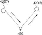
图15绘示为于二个三维区块的连结上找出基准参考点的示意图。FIG. 15 is a schematic diagram of finding a reference point on the connection of two 3D blocks.
图16绘示为第一种三维区块类型示意图。FIG. 16 is a schematic diagram of the first three-dimensional block type.
图17绘示为第二种三维区块类型示意图。FIG. 17 is a schematic diagram of the second three-dimensional block type.
图18绘示为第三种三维区块类型示意图。FIG. 18 is a schematic diagram of the third three-dimensional block type.
图19绘示为连接群组的示意图。FIG. 19 is a schematic diagram of connection groups.
【主要元件符号说明】[Description of main component symbols]
10:三维控制端点的辨识系统10: Identification system of 3D control endpoints
21~25、221~225、231~233、241~243:步骤21~25, 221~225, 231~233, 241~243: steps
410、410(1)~410(4):凸点410, 410(1)~410(4): bump
50:参考平面50: Reference plane
60(1)、60(2):连接群组60(1), 60(2): Connection groups
110:计算机110: Computer
120:计算机可读介质120: Computer-readable media
420、420(a)、420(b)、420(1)~420(9):三维区块420, 420(a), 420(b), 420(1)~420(9): three-dimensional blocks
430:基准参考点430: datum reference point
具体实施方式Detailed ways
为了正确地辨识出控制端点,下述实施例提供一种三维控制端点的辨识方法及使用其的计算机可读介质。计算机可读介质具有数个程序指令以执行一三维控制端点的辨识方法,三维控制端点的辨识方法包括:接收深度信息,深度信息相关于图像撷取装置所撷取的图像;根据深度信息产生相关于三维区块的三维区块信息;根据深度信息产生参考平面;根据三维区块信息及参考平面产生连接群组;以及选择连接群组中最接近图像撷取装置的三维区块做为控制端点。In order to correctly identify control endpoints, the following embodiments provide a method for identifying three-dimensional control endpoints and a computer-readable medium using the same. The computer readable medium has several program instructions to execute a method for identifying a three-dimensional control endpoint. The method for identifying a three-dimensional control endpoint includes: receiving depth information, the depth information is related to an image captured by an image capture device; generating a correlation according to the depth information 3D block information in the 3D block; generating a reference plane according to the depth information; generating a connection group according to the 3D block information and the reference plane; and selecting the 3D block closest to the image capture device in the connection group as a control endpoint .
三维控制端点的辨识方法及计算机可读介质Three-dimensional control endpoint identification method and computer readable medium
请同时参照图1及图2,图1绘示为一种三维控制端点的辨识系统,图2绘示为一种三维控制端点的辨识方法的流程图。三维控制端点的辨识系统10包括计算机110及计算机可读介质(Computer-Readable Medium)120。计算机可读介质120具有数个程序指令,供计算机110载入以执行三维控制端点的辨识方法。计算机可读介质120例如为磁盘、光盘、磁带或是硬盘机。三维控制端点的辨识方法包括如下步骤:首先如步骤21所示,接收深度信息。深度信息相关于一图像撷取装置所撷取的图像,而图像撷取装置例如为红外线摄影机或双摄影机。Please refer to FIG. 1 and FIG. 2 at the same time. FIG. 1 shows a three-dimensional control endpoint identification system, and FIG. 2 shows a flow chart of a three-dimensional control endpoint identification method. The
接着如步骤22所示,根据深度信息产生相关于三维区块的三维区块信息。跟着如步骤23所示,根据深度信息产生参考平面。然后如步骤24所示,根据三维区块信息及参考平面产生连接群组。最后如步骤25所示,从连接群组中选择最接近图像撷取装置的三维区块做为控制端点。后续将进一步分别说明产生三维区块信息、参考平面及连接群组的步骤。Next, as shown in
产生三维区块信息Generate 3D block information
请同时参照图3至图8,图3绘示为产生三维区块信息的细部流程图,图4绘示为凸点的示意图,图5绘示为滤除噪声区块前的示意图,图6绘示为滤除噪声区块后的示意图,图7绘示为图像中所有凸点的示意图,图8绘示为图像中所有三维区块的示意图。前述步骤22进一步包括步骤221至225。Please refer to FIG. 3 to FIG. 8 at the same time. FIG. 3 is a detailed flow chart for generating three-dimensional block information. FIG. 4 is a schematic diagram of bumps. FIG. 5 is a schematic diagram before filtering out noise blocks. FIG. 6 It is a schematic diagram after filtering noise blocks, FIG. 7 is a schematic diagram of all bumps in the image, and FIG. 8 is a schematic diagram of all three-dimensional blocks in the image. The foregoing
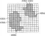
首先如步骤221所示,根据深度信息沿水平方向及垂直方向检测出图像撷取装置所撷取的图像中所有凸点410。所谓的凸点410是指在一个图像中存在一个相对于其他周边更为隆起的一定高度的特征像素点(如图4绘示)。First, as shown in step 221 , all
接着如步骤222所示,根据凸点410与凸点410的周边像素点的深度差异将图7绘示的凸点410扩展为图8绘示的三维区块420。需说明的是,步骤222系检查凸点410周边所有像素点的深度信息。当凸点410周边所有像素点的深度差异在一预设范围内时,即将凸点410周边深度差异在一预设范围内的像素点纳入扩展范围内,使得凸点410扩展为三维区块420。Next, as shown in step 222 , the
跟着如步骤223所示,根据深度变化过滤三维区块420中的噪声区块。需说明的是,步骤223也可与步骤222同步执行。举例来说,在图5绘示的凸点410(1)扩展时,扩展的动作接触到另一个凸点410(2)。此时步骤223即将凸点410(2)与凸点410(1)的深度信息进行比对。当凸点410(2)的深度差异在一预设范围内时,我们便会将凸点410(2)融入凸点410(1)的扩展范围内,并且去除掉凸点410(2)扩展的权力(如图6绘示),而凸点410(1)扩展为三维区块420(a)。相似地,当凸点410(4)的深度差异在一预设范围内时,我们便会将凸点410(4)融入凸点410(3)的扩展范围内,并且去除掉凸点410(4)扩展的权力,而凸点410(3)扩展为三维区块420(b)。藉此,我们可以简化前述步骤222的运算次数,并在准确度不变的前提下达到加速的效果。Then, as shown in step 223 , the noise blocks in the
然后如步骤224所示,判断图像中所有凸点410是否检查完毕,如果否则重复前述步骤222及步骤223。不过在步骤223中被去除扩展的权力的凸点将不会再纳入运算,如图5及图6绘示的凸点410(2)及凸点410(4)。步骤224会重复检查直到前述步骤221中所检测的所有凸点410都被检查完毕为止。Then, as shown in step 224, it is judged whether all
接着如步骤225所示,产生相关于三维区块420的三维区块信息。进一步来说,当前述步骤224找出所有三维区块420后,步骤225系先于所有三维区块420分别找出代表点,代表点例如为三维区块420的重心。当三维区块420的代表点决定后,再产生相关于代表点的三维区块信息。Next, as shown in step 225 , the 3D block information related to the
产生参考平面generate reference plane
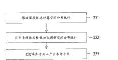
请同时参照图9至图10,图9绘示为产生参考平面的细部流程图,图10绘示为空间分布统计的示意图。前述步骤23进一步包括步骤231至233。首先如步骤231所示,根据深度信息计算空间分布统计。进一步来说,步骤231通过深度信息评估图像中每一个像素在三维空间的对应位置,进而重建一个三维场景。藉此通过三维场景可得到如图10绘示的空间分布统计。在图10中,原点表示图像撷取装置所在位置,而x轴表示距离图像撷取装置的远近,y轴则表示像素个数的多寡。由于x轴表示距离图像撷取装置的远近,因此图10绘示的空间分布统计即表示不同深度下的像素个数。Please refer to FIG. 9 to FIG. 10 at the same time. FIG. 9 is a detailed flowchart of generating a reference plane, and FIG. 10 is a schematic diagram of spatial distribution statistics. The foregoing
接着如步骤232所示,区间平滑化及整体加权调整图10绘示的空间分布统计。进一步来说,为了去除空间分布统计中小细节噪声的影响,步骤232利用模糊化的作法,平滑了原始的空间分布统计,减轻小细节噪声的影响。举例来说,步骤232可选择取一定范围的深度区段(y轴坐标中一定大小的区域),将深度区段所对应的像素加总后平均取得此深度区段的代表值。接着,再逐步移动此深度区段并且重复进行前述运算,让这些噪声不会影响到其后的运算,接下来通过与摄影机距离的关系,加权评估整体的空间分布统计,进而达到整体加权调整的目标。Next, as shown in
跟着如步骤233所示,过滤噪声平面以产生参考平面。进一步来说,为了在图10绘示的空间分布统计中找出适格的参考平面,步骤233会先找出空间分布统计中的最高峰值ymax,并以最高峰值ymax为基准产生评估标准。举例来说,以最高峰值ymax的30%为判定依据,如果有一个峰值的像素值没有超过这个基准值则不会被选取为适合的参考平面,而被判定成噪声平面后过滤。经由步骤233的过滤运算后,图10绘示的空间分布统计中可以发现y1合乎要求。步骤233再以最高峰值ymax及峰值y1为基准,分析出峰值区间内的x轴的空间像素分布图,分割出近似深度的不同使用者的参考平面。Next, as shown in
产生连接群组generate connection group
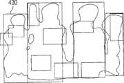
请同时图11至图19,图11绘示为产生连接群组的细部流程图,图12绘示为第一种三维区块连接结果示意图,图13绘示为第二种三维区块连接结果示意图,图14绘示为第三种三维区块连接结果示意图,图15绘示为于二个三维区块的连结上找出基准参考点的示意图,图16绘示为第一种三维区块类型示意图,图17绘示为第二种三维区块类型示意图,图18绘示为第三种三维区块类型示意图,图19绘示为连接群组的示意图。当前述三维区块信息及三维区块信息产生完毕后,前述步骤24即可根据三维区块信息及参考平面分析出三维区块间的连结性,并且依照三维区块的连结性去产生连接群组。前述步骤24进一步包括步骤241至243。Please see Figure 11 to Figure 19 at the same time, Figure 11 is a detailed flowchart for generating a connection group, Figure 12 is a schematic diagram of the first type of 3D block connection results, and Figure 13 is a diagram of the second type of 3D block connection results Schematic diagram, Figure 14 is a schematic diagram of the connection result of the third three-dimensional block, Figure 15 is a schematic diagram of finding a reference point on the connection of two three-dimensional blocks, and Figure 16 is a schematic diagram of the first three-dimensional block Type schematic diagram, FIG. 17 is a schematic diagram of the second three-dimensional block type, FIG. 18 is a schematic diagram of the third three-dimensional block type, and FIG. 19 is a schematic diagram of a connection group. After the aforementioned 3D block information and 3D block information are generated, the
首先如步骤241所示,根据三维区块之间的距离将距离相近的三维区块相连接。进一步来说,步骤241会依照三维区块之间的距离将相近的三维区块连接在一起,而三维区块之间的距离可通过欧几里德距离来计算区块间的距离。一般来说,三维区块420(1)至420(3)正确的连接方向应是如图12绘示朝向参考平面50进行连接,且三维区块420(4)至420(6)正确的连接方向也应是如图12绘示朝向参考平面50进行连接。然而,如果单纯地仅以欧几里德距离来评估二个三维区块是否相连时,则有可能会发生如图13或图14绘示的连接错误。为了避免错误连接的情事发生,步骤241利用欧几里德距离找出最接近的三维区块后,尚须通过后续步骤242检查三维区块间的连接是否正确。如果三维区块间的连接无法通过步骤242的检查时,便需重回到步骤241。当回到步骤241后,则需找出次接近的三维区块,并再次通过后续步骤242检查。First, as shown in
接着如步骤242所示,在相连接的二个三维区块的连结上找出深度最低的一点做为基准参考点430,并根据基准参考点430判断连结是否符合预设连接状态,如果连结不符合预设连接状态,则重复执行步骤241。进一步来说,如图15绘示,步骤241先将三维区块420(7)及420(8)连线上所有的点的深度计算出来,再从这些点中找出深度最底的点,并且定义深度最底的点为基准参考点430。当深度最底的点和基准参考点430的关系如图16绘示时,表示三维区块420(7)及420(8)连结上没有相对低的基准参考点430。这样的连接代表沿着手部往参考平面连接,所以图16绘示的三维区块420(7)及420(8)的连结符合预设连接状态。Then, as shown in
此外,当深度最底的点和基准参考点430的关系如图17绘示时,表示基准参考点430虽低于三维区块420(7)及420(8),但基准参考点430与三维区块420(7)及420(8)的距离在一定的限度内。就连结的整体性看来,图17绘示仍旧是向着参考平面进行连接,所以图17绘示的三维区块420(7)及420(8)的连结符合预设连接状态。In addition, when the relationship between the point at the bottom of the depth and the
另外,当深度最底的点和基准参考点430的关系如图18绘示时,表示基准参考点430远低于三维区块420(7)及420(8)。如果三维区块420(7)及420(8)分别为双手之前端,而基准参考点430在参考平面上。此时就算三维区块420(7)及420(8)靠的再近,三维区块420(7)及420(8)间的连接关也不合乎预设连接状态。因此三维区块420(7)及420(8)不会被连接。需重回到步骤241,并找出次接近的三维区块。In addition, when the relationship between the bottommost point and the
同理,不论二个人靠的再近,只要其手部端点的三维区块连线上存在一个陷落的基准参考点430,我们就不会将其连接起来。如此一来可以克服多点对应在多人意欲进行操作时彼此互相干扰的问题,以确保三维区块间的连接符合预设的连接状态。In the same way, no matter how close two people are, as long as there is a submerged
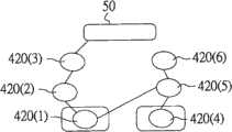
跟着如步骤243所示,集合彼此相连且连回参考平面的三维区块以产生连接群组。进一步来说,如图19绘示,如果三维区块420(1)及420(4)可以正确连回参考平面50时,则三维区块420(1)及420(4)为合理的控制端点。相反地,如果三维区块420(9)无法正确连回参考平面50时,则三维区块420(9)无法成为合理的控制端点,而为空间中的噪声。藉此,步骤243集合彼此相连且连回参考平面的三维区块420(1)至420(3)以产生连接群组60(1),并集合彼此相连且连回参考平面的三维区块420(4)至420(6)以产生连接群组60(2)。之后前述步骤25可在连接群组60(1)及连接群组60(2)中选择最接近图像撷取装置的三维区块420(1)及420(4)做为控制端点。Next, as shown in
本发明上述实施例所公开的三维控制端点的辨识方法及计算机可读介质,具有多项优点,以下仅列举部分优点说明如下:The identification method of the three-dimensional control endpoint and the computer-readable medium disclosed in the above-mentioned embodiments of the present invention have many advantages, and only some of the advantages are listed below:
一、在复杂背景中亦能正确地检测出控制端点。1. Control endpoints can be detected correctly even in complex backgrounds.
二、不需限定使用者的操作位置及距离。2. There is no need to limit the user's operating position and distance.
三、能以人体类型趋势找出最正确的控制端点,并将多人操作时彼此造成的影响降到最低。3. The most correct control endpoint can be found based on the trend of human body type, and the mutual influence caused by multiple people during operation can be minimized.
综上所述,虽然本发明已以一优选实施例公开如上,然其并非用以限定本发明。本发明所属领域技术人员,在不脱离本发明的精神和范围内,当可作各种的更动与润饰。因此,本发明的保护范围当视所附权利要求书所界定者为准。In summary, although the present invention has been disclosed as above with a preferred embodiment, it is not intended to limit the present invention. Those skilled in the art to which the present invention belongs may make various changes and modifications without departing from the spirit and scope of the present invention. Therefore, the protection scope of the present invention should be defined by the appended claims.
Claims (10)
Priority Applications (1)
| Application Number | Priority Date | Filing Date | Title |
|---|---|---|---|
| CN 201010225545CN102331883B (en) | 2010-07-14 | 2010-07-14 | Identification method of three-dimensional control endpoint and computer readable medium using same |
Applications Claiming Priority (1)
| Application Number | Priority Date | Filing Date | Title |
|---|---|---|---|
| CN 201010225545CN102331883B (en) | 2010-07-14 | 2010-07-14 | Identification method of three-dimensional control endpoint and computer readable medium using same |
Publications (2)
| Publication Number | Publication Date |
|---|---|
| CN102331883A CN102331883A (en) | 2012-01-25 |
| CN102331883Btrue CN102331883B (en) | 2013-11-06 |
Family
ID=45483680
Family Applications (1)
| Application Number | Title | Priority Date | Filing Date |
|---|---|---|---|
| CN 201010225545ActiveCN102331883B (en) | 2010-07-14 | 2010-07-14 | Identification method of three-dimensional control endpoint and computer readable medium using same |
Country Status (1)
| Country | Link |
|---|---|
| CN (1) | CN102331883B (en) |
Families Citing this family (2)
| Publication number | Priority date | Publication date | Assignee | Title |
|---|---|---|---|---|
| CN112000824A (en)* | 2019-05-27 | 2020-11-27 | 英业达科技有限公司 | Object identification system and method thereof |
| CN111127633A (en)* | 2019-12-20 | 2020-05-08 | 支付宝(杭州)信息技术有限公司 | Three-dimensional reconstruction method, apparatus, and computer-readable medium |
Citations (3)
| Publication number | Priority date | Publication date | Assignee | Title |
|---|---|---|---|---|
| US5734743A (en)* | 1994-07-12 | 1998-03-31 | Canon Kabushiki Kaisha | Image processing method and apparatus for block-based corresponding point extraction |
| US20090285283A1 (en)* | 2006-07-17 | 2009-11-19 | Yong Ying Gao | Method and apparatus for encoding video color enhancement data, and method and apparatus for decoding video color enhancement data |
| CN101689299A (en)* | 2007-06-20 | 2010-03-31 | 汤姆逊许可证公司 | System and method for stereo matching of images |
- 2010
- 2010-07-14CNCN 201010225545patent/CN102331883B/enactiveActive
Patent Citations (3)
| Publication number | Priority date | Publication date | Assignee | Title |
|---|---|---|---|---|
| US5734743A (en)* | 1994-07-12 | 1998-03-31 | Canon Kabushiki Kaisha | Image processing method and apparatus for block-based corresponding point extraction |
| US20090285283A1 (en)* | 2006-07-17 | 2009-11-19 | Yong Ying Gao | Method and apparatus for encoding video color enhancement data, and method and apparatus for decoding video color enhancement data |
| CN101689299A (en)* | 2007-06-20 | 2010-03-31 | 汤姆逊许可证公司 | System and method for stereo matching of images |
Also Published As
| Publication number | Publication date |
|---|---|
| CN102331883A (en) | 2012-01-25 |
Similar Documents
| Publication | Publication Date | Title |
|---|---|---|
| CN108475433B (en) | Method and system for large-scale determination of RGBD camera pose | |
| CN102662460B (en) | Non-contact control device of mobile terminal and control method thereof | |
| US9995578B2 (en) | Image depth perception device | |
| JP5454821B2 (en) | System and method for generating a robust depth map utilizing a multi-resolution procedure | |
| US20130050076A1 (en) | Method of recognizing a control command based on finger motion and mobile device using the same | |
| KR101032446B1 (en) | Apparatus and method for detecting vertices of images | |
| CN107958446B (en) | Information processing apparatus, information processing method, and computer program | |
| CN102591533B (en) | Multipoint touch screen system realizing method and device based on computer vision technology | |
| WO2016122872A1 (en) | Occlusion handling for computer vision | |
| WO2018027533A1 (en) | Camera configuration method and device | |
| CN116778094B (en) | A method and device for monitoring building deformation based on optimal viewing angle shooting | |
| CN104200426A (en) | Image interpolation method and device | |
| CN103761011B (en) | A kind of method of virtual touch screen, system and the equipment of calculating | |
| CN102663814A (en) | Automatic modeling method utilizing two dimensional image to generate three dimensional geometric model | |
| CN107292238A (en) | Contour of building recognition methods with end point is constrained based on spatial topotaxy | |
| JP5555193B2 (en) | Data processing apparatus, data processing system, and program | |
| CN102331883B (en) | Identification method of three-dimensional control endpoint and computer readable medium using same | |
| JP5416489B2 (en) | 3D fingertip position detection method, 3D fingertip position detection device, and program | |
| CN107506133B (en) | Method and system for operating trajectory response of projection touch system | |
| TWI431512B (en) | Method for recognizing three-dimensional control point and computer readable medium using the same thereof | |
| CN104777944A (en) | Method for simulating hand-drawing board based on pen shadow detection | |
| KR20120071287A (en) | Apparatus and method for tracking position using webcam | |
| Lee et al. | A Hand gesture recognition system based on difference image entropy | |
| TWI507919B (en) | Method for tracking and recordingfingertip trajectory by image processing | |
| JP2018059767A (en) | Image processing device, image processing method and program |
Legal Events
| Date | Code | Title | Description |
|---|---|---|---|
| C06 | Publication | ||
| PB01 | Publication | ||
| C10 | Entry into substantive examination | ||
| SE01 | Entry into force of request for substantive examination | ||
| C14 | Grant of patent or utility model | ||
| GR01 | Patent grant |