CN102325065A - A dual-channel digital home control and interaction system and its implementation method - Google Patents
A dual-channel digital home control and interaction system and its implementation methodDownload PDFInfo
- Publication number
- CN102325065A CN102325065ACN201110201602ACN201110201602ACN102325065ACN 102325065 ACN102325065 ACN 102325065ACN 201110201602 ACN201110201602 ACN 201110201602ACN 201110201602 ACN201110201602 ACN 201110201602ACN 102325065 ACN102325065 ACN 102325065A
- Authority
- CN
- China
- Prior art keywords
- power line
- dual
- control
- communication module
- module
- Prior art date
- Legal status (The legal status is an assumption and is not a legal conclusion. Google has not performed a legal analysis and makes no representation as to the accuracy of the status listed.)
- Pending
Links
- 238000000034methodMethods0.000titleclaimsabstractdescription21
- 230000003993interactionEffects0.000titleclaimsabstractdescription12
- 238000004891communicationMethods0.000claimsabstractdescription123
- 230000008878couplingEffects0.000claimsabstractdescription29
- 238000010168coupling processMethods0.000claimsabstractdescription29
- 238000005859coupling reactionMethods0.000claimsabstractdescription29
- 230000005540biological transmissionEffects0.000claimsabstractdescription17
- 230000002452interceptive effectEffects0.000claimsdescription7
- 230000008569processEffects0.000claimsdescription6
- 239000003990capacitorSubstances0.000claimsdescription4
- 230000001629suppressionEffects0.000claimsdescription4
- 230000001052transient effectEffects0.000claimsdescription4
- 230000009977dual effectEffects0.000claims2
- 238000010586diagramMethods0.000description10
- 230000006855networkingEffects0.000description5
- 238000005516engineering processMethods0.000description3
- 230000001360synchronised effectEffects0.000description2
- 235000015429Mirabilis expansaNutrition0.000description1
- 244000294411Mirabilis expansaSpecies0.000description1
- 230000003111delayed effectEffects0.000description1
- 238000001514detection methodMethods0.000description1
- 238000002955isolationMethods0.000description1
- 235000013536misoNutrition0.000description1
- 230000035515penetrationEffects0.000description1
Images


Landscapes
- Cable Transmission Systems, Equalization Of Radio And Reduction Of Echo (AREA)
- Small-Scale Networks (AREA)
Abstract
Translated fromChineseDescription
Translated fromChinese技术领域technical field
本发明属于数字家庭智能控制技术领域,特别是一种双通道的数字家庭控制及交互系统及实现方法。The invention belongs to the technical field of digital home intelligent control, in particular to a dual-channel digital home control and interaction system and an implementation method.
背景技术Background technique
数字家庭是信息产业向消费电子领域发展的一个分支,它为用户提供产品、消费和娱乐等数字化生活,是产、官、学界一致认定的数字汇流发展中的重要应用领域。其中数字家庭的一个重要体现就是智能家居。The digital home is a branch of the information industry that is developing into the field of consumer electronics. It provides users with digital life such as products, consumption, and entertainment. An important embodiment of the digital home is the smart home.
目前,由于电力线具有不需要重复布线,扩展容易,普及率高的特点,而受到智能家居控制领域的青睐。通过电力线,并结合PLC总线控制技术,不仅可以实现控制信号的安全传输问题,更可以节省家庭网络的投资,实现快速组网,相对与其它网络控制方法,电力线仍然存在调制解调麻烦,数据交互速率低等缺点。At present, because the power line does not require repeated wiring, is easy to expand, and has a high penetration rate, it is favored by the field of smart home control. Through the power line, combined with the PLC bus control technology, not only the safe transmission of control signals can be realized, but also the investment in the home network can be saved, and fast networking can be realized. Compared with other network control methods, the power line still has the trouble of modulation and demodulation, and data interaction. Disadvantages such as low speed.
随着WIFI等无线局域的通讯技术的发展,目前都市家庭中具有组网功能的家电越来越多,并且网络化发展也将是未来家电发展的必然趋势。With the development of wireless local area communication technologies such as WIFI, there are more and more home appliances with networking functions in urban households, and the development of networking will also be an inevitable trend in the development of home appliances in the future.
中国专利申请02103815.5(数字家庭网络系统)提供一种可以通过移动终端控制与网络终端控制相结合对家庭网络家电进行控制的方法,即多台智能家电既可以使用一个移动控制终端进行控制,也可以在INTERNET上通过网络控制终端进行控制的方法。数字家庭网络系统,包括物理层、网络层和应用层,其特点在于:该数字家庭网络包括网络控制终端、移动控制终端和通讯模块;所述网络控制终端以有线的方式与外部接入网,以有线通讯和无线通讯的方式与家庭内部网络连接;所述移动控制终端以无线通讯的方式接收通讯信号,并且传递信号家庭内部的各种设备;所述通讯模块可以从有线通讯和无线通讯的方式接收通讯信号,通过有线通讯和无线通讯的方式传递信号给家庭内部的各种设备。但是没有结合数字家庭智能控制的需要而提出一种能充分发挥并有机整合电力线总线组网和无线组网的优势的方案。Chinese patent application 02103815.5 (Digital Home Network System) provides a method for controlling home network home appliances through the combination of mobile terminal control and network terminal control, that is, multiple smart home appliances can be controlled by one mobile control terminal, or A method of controlling through a network control terminal on the Internet. The digital home network system includes a physical layer, a network layer and an application layer, and is characterized in that: the digital home network includes a network control terminal, a mobile control terminal and a communication module; the network control terminal communicates with an external access network in a wired manner, It is connected to the home network by wired communication and wireless communication; the mobile control terminal receives communication signals by wireless communication, and transmits signals to various devices in the home; the communication module can communicate from wired communication and wireless communication The communication signal is received by means of communication, and the signal is transmitted to various devices in the home through wired communication and wireless communication. However, a solution that can fully utilize and organically integrate the advantages of power line bus networking and wireless networking has not been proposed in combination with the needs of digital home intelligent control.
发明内容Contents of the invention
本发明的目的是克服现有技术的缺点,提供结合PLC电力总线网络通讯和WIFI无线通讯优势的双通道的数字家庭控制及交互系统及实现方法。The purpose of the present invention is to overcome the shortcomings of the prior art, and provide a dual-channel digital home control and interactive system and implementation method combining the advantages of PLC power bus network communication and WIFI wireless communication.
下面对本发明方案做进一步描述:The scheme of the present invention is further described below:
一种双通道的数字家庭控制及交互系统,包括控制终端、家庭网关、电力线、双通道通讯装置和受控终端,控制终端与家庭网关通过有线或无线通讯的方式连接;家庭网关与双通道通讯装置通过电力线相连及数据交互,受控终端与双通道通讯装置连接并执行来自双通道通讯装置的执行指令,其特征在于:A dual-channel digital home control and interactive system, including a control terminal, a home gateway, a power line, a dual-channel communication device, and a controlled terminal. The control terminal and the home gateway are connected by wired or wireless communication; the home gateway communicates with the dual-channel The device is connected and data exchanged through the power line, and the controlled terminal is connected with the dual-channel communication device and executes the execution instructions from the dual-channel communication device, which is characterized in that:
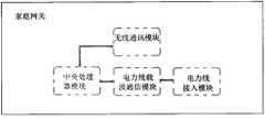
所述的家庭网关至少具有一电力线载波通讯模块、一电力线接入模块和一无线通讯模块;电力线载波通讯模块将来自控制终端的控制指令转换成适合电力线传输指令电信号并通过电力线接入模块实现与电力线载波的耦合和收发;无线通讯模块用于无线接收来自控制终端的控制请求,并实现与双通道通讯装置及受控终端之间的业务数据交互;The home gateway at least has a power line carrier communication module, a power line access module and a wireless communication module; the power line carrier communication module converts the control command from the control terminal into an electrical signal suitable for power line transmission instructions and realizes it through the power line access module Coupling and sending and receiving with the power line carrier; the wireless communication module is used to wirelessly receive the control request from the control terminal, and realize the business data interaction with the dual-channel communication device and the controlled terminal;
所述的双通道通讯装置至少具有一电力线接入模块、电力线载波通讯模块、无线通讯模块和控制执行模块;双通道通讯装置的电力线接入模块接收电力线的控制信号并经过电力线载波通讯模块解调及转换成控制执行模块可执行的指令;双通道通讯装置的无线通讯模块用于实现与家庭网关的业务数据交互。The dual-channel communication device at least has a power line access module, a power line carrier communication module, a wireless communication module and a control execution module; the power line access module of the dual-channel communication device receives the control signal of the power line and demodulates it through the power line carrier communication module And convert it into executable instructions of the control execution module; the wireless communication module of the dual-channel communication device is used to realize the business data interaction with the home gateway.
进一步,所述的电力线用于传输来自家庭网关控制指令信号;受控终端响应并执行该控制指令过程中形成的业务数据主体通过家庭网关和双通道通讯装置的无线通讯模块无线交互。Further, the power line is used to transmit the control instruction signal from the home gateway; the service data subject formed during the process of the controlled terminal responding and executing the control instruction interacts wirelessly with the wireless communication module of the dual-channel communication device through the home gateway.
更进一步,所述的家庭网关的电力线载波通讯模块至少具有两个模拟信号接收端的差分输入端和两个数字功放的半桥输出端;电力线接入模块包括电力线耦合电路、电力线载波发送电路和电力线载波接收电路;Furthermore, the power line carrier communication module of the home gateway has at least two differential input terminals of analog signal receiving terminals and half-bridge output terminals of two digital power amplifiers; the power line access module includes a power line coupling circuit, a power line carrier transmission circuit and a power line Carrier receiving circuit;
电力线耦合电路的信号耦合变压器两边分别并联一个双极型瞬态抑制二极管以避免线路上高电压脉冲冲击,信号耦合变压器与电力线接入的一边至少并联一用以过压保护的压敏电阻;A bipolar transient suppression diode is connected in parallel to both sides of the signal coupling transformer of the power line coupling circuit to avoid high-voltage pulse impact on the line, and at least one varistor for overvoltage protection is connected in parallel between the signal coupling transformer and the side connected to the power line;
电力线载波通讯模块的两个数字功放的半桥输出端分别通过一LC带通滤波器后与电力线耦合电路相连形成电力线载波发送电路;The half-bridge output ends of the two digital power amplifiers of the power line carrier communication module are respectively connected to the power line coupling circuit after passing through an LC bandpass filter to form a power line carrier transmission circuit;
电力线载波通讯模块的两个模拟信号接收端的差分输入端连接一LC谐振电路,并分别经由一电阻和电容后与两个数字功放的半桥输出端实现并接,并形成电力线载波接收电路。The differential input terminals of the two analog signal receiving terminals of the power line carrier communication module are connected to an LC resonant circuit, and are connected in parallel with the half-bridge output terminals of the two digital power amplifiers through a resistor and a capacitor respectively to form a power line carrier receiving circuit.
下面为基于上所述的一种双通道的数字家庭控制及交互系统的一种实现方法,其特征在于:The following is an implementation method based on the above-mentioned a kind of dual-channel digital home control and interactive system, which is characterized in that:
该方法包括如下步骤The method includes the following steps
步骤一,通过控制终端的客户端/控制界面形成控制指令;
步骤二,控制终端将控制指令无线发送并被家庭网关的无线通讯模块接收;
步骤三,家庭网关的电力线载波通讯模块将控制指令转换成适合电力线传输指令电信号并通过电力线接入模块实现与电力线载波的耦合和收发;
步骤四,电力线传输来自家庭网关电力线载波通讯模块的指令信号,并被双通道通讯装置的电力线接入模块、电力线载波通讯模块的接收、解调和转换成控制执行模块可执行的指令;
步骤五,双通道通讯装置或受控终端响应控制指令,并形成反馈数据或相关的业务数据,并经由双通道通讯装置的无线通讯模块与家庭网关交互;
步骤六,家庭网关将反馈数据或相关的业务数据经过处理或直接转发至控制终端。In step six, the home gateway processes or directly forwards the feedback data or related service data to the control terminal.
附图说明Description of drawings
图1是本发明系统的整体结构框图;Fig. 1 is the overall structural block diagram of the system of the present invention;
图2是家庭网关的内部结构框图;Fig. 2 is a block diagram of the internal structure of the home gateway;
图3是双通道通讯装置的内部结构框图;Fig. 3 is a block diagram of the internal structure of the dual-channel communication device;
图4是MI200E电力线载波芯片引脚分布图;Figure 4 is a pin distribution diagram of the MI200E power line carrier chip;
图5是电力线耦合电路原理图;Fig. 5 is a schematic diagram of a power line coupling circuit;
图6是电力线载波发送电路原理图;Fig. 6 is a schematic diagram of a power line carrier transmission circuit;
图7是电力线载波接收电路原理图;Fig. 7 is a schematic diagram of a power line carrier receiving circuit;
图8是MCU模块与电力线载波通讯模块的SPI接口电路原理图。Fig. 8 is a schematic diagram of the SPI interface circuit between the MCU module and the power line carrier communication module.
具体实施方式Detailed ways
实施例一Embodiment one
如图1,本发明的双通道的数字家庭控制及交互系统,由控制终端、家庭网关、电力线、双通道通讯装置和受控终端组成,其中控制终端与家庭网关通过有线或无线通讯的方式连接;家庭网关与双通道通讯装置通过电力线相连及数据交互,受控终端与双通道通讯装置连接并执行来自双通道通讯装置的执行指令。电力线用于传输来自家庭网关控制指令信号;受控终端响应并执行该控制指令过程中形成的业务数据主体通过家庭网关和双通道通讯装置的无线通讯模块无线交互。As shown in Figure 1, the dual-channel digital home control and interactive system of the present invention is composed of a control terminal, a home gateway, a power line, a dual-channel communication device and a controlled terminal, wherein the control terminal and the home gateway are connected by wired or wireless communication ; The home gateway is connected to the dual-channel communication device through a power line and exchanges data, and the controlled terminal is connected to the dual-channel communication device and executes execution instructions from the dual-channel communication device. The power line is used to transmit the control instruction signal from the home gateway; the subject of business data formed during the process of the controlled terminal responding and executing the control instruction interacts wirelessly with the wireless communication module of the home gateway and the dual-channel communication device.
如图2所示,家庭网关至少具有一电力线载波通讯模块、一电力线接入模块和一无线通讯模块;电力线载波通讯模块将来自控制终端的控制指令转换成适合电力线传输指令电信号并通过电力线接入模块实现与电力线载波的耦合和收发;无线通讯模块用于无线接收来自控制终端的控制请求,并实现与双通道通讯装置及受控终端之间的业务数据交互。另外,家庭网关还具有一中央处理器模块,在这里可采用MCU模块(如图8所示)。As shown in Figure 2, the home gateway at least has a power line carrier communication module, a power line access module and a wireless communication module; The input module realizes the coupling and sending and receiving with the power line carrier; the wireless communication module is used to wirelessly receive the control request from the control terminal, and realize the business data interaction with the dual-channel communication device and the controlled terminal. In addition, the home gateway also has a central processing unit module, where an MCU module (as shown in FIG. 8 ) can be used.
如图3所示,双通道通讯装置至少具有一电力线接入模块、电力线载波通讯模块、无线通讯模块和控制执行模块;双通道通讯装置的电力线接入模块接收电力线的控制信号并经过电力线载波通讯模块解调及转换成控制执行模块可执行的指令;双通道通讯装置的无线通讯模块用于实现与家庭网关的业务数据交互。As shown in Figure 3, the dual-channel communication device has at least one power line access module, power line carrier communication module, wireless communication module, and control execution module; the power line access module of the dual-channel communication device receives the control signal of the power line and passes the The module demodulates and converts them into executable instructions of the control execution module; the wireless communication module of the dual-channel communication device is used to realize the business data interaction with the home gateway.
如图4至8所示,家庭网关的电力线载波通讯模块至少具有两个模拟信号接收端的差分输入端和两个数字功放的半桥输出端;电力线接入模块包括电力线耦合电路、电力线载波发送电路和电力线载波接收电路;电力线耦合电路的信号耦合变压器两边分别并联一个双极型瞬态抑制二极管以避免线路上高电压脉冲冲击,信号耦合变压器与电力线接入的一边至少并联一用以过压保护的压敏电阻;电力线载波通讯模块的两个数字功放的半桥输出端分别通过一LC带通滤波器后与电力线耦合电路相连形成电力线载波发送电路;电力线载波通讯模块的两个模拟信号接收端的差分输入端连接一LC谐振电路,并分别经由一电阻和电容后与两个数字功放的半桥输出端实现并接,并形成电力线载波接收电路。As shown in Figures 4 to 8, the power line carrier communication module of the home gateway has at least two differential input terminals of analog signal receiving terminals and two half-bridge output terminals of digital power amplifiers; the power line access module includes a power line coupling circuit and a power line carrier transmission circuit And the power line carrier receiving circuit; the signal coupling transformer of the power line coupling circuit is connected in parallel with a bipolar transient suppression diode to avoid high voltage pulse impact on the line, and the signal coupling transformer is connected in parallel with at least one side of the power line for overvoltage protection The varistor; the half-bridge output terminals of the two digital power amplifiers of the power line carrier communication module are respectively connected to the power line coupling circuit through an LC band-pass filter to form a power line carrier transmission circuit; the two analog signal receiving ends of the power line carrier communication module The differential input terminal is connected to an LC resonant circuit, and connected in parallel with the half-bridge output terminals of two digital power amplifiers through a resistor and a capacitor respectively to form a power line carrier receiving circuit.
其中如图4,为电力线载波通讯模块所采用的MI200E电力线载波芯片引脚分布图。MI200E电力线载波芯片是一款专门针对低压电力线进行优化设计的高集成度、高性能的电力线载波通讯芯片。它是一个可工作于码分多址(CDMA)方式的半双工调制解调芯片,并且提供载波侦听和有效帧指示信号,可方便地实现基于共享信道的网络接入协议。作为电力线载波通讯模块的核心,MI200E电力线载波芯片具有两个模拟信号接收端的差分输入端(RAI+、RAI-)和两个数字功放的半桥输出端(PA、PB)。Among them, Fig. 4 is a pin distribution diagram of the MI200E power line carrier chip adopted by the power line carrier communication module. MI200E power line carrier chip is a highly integrated and high-performance power line carrier communication chip specially optimized for low-voltage power lines. It is a half-duplex modem chip that can work in code division multiple access (CDMA) mode, and provides carrier sense and effective frame indication signal, and can easily realize network access protocol based on shared channel. As the core of the power line carrier communication module, the MI200E power line carrier chip has two differential input terminals (RAI+, RAI-) of analog signal receivers and two half-bridge output terminals of digital power amplifiers (PA, PB).
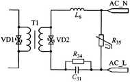
如图5至8,电力线接入模块由电力线耦合电路、电力线载波发送电路和电力线载波接收电路三部分组成。其中如图2所示,电力线耦合电路的信号耦合变压器T1两边分别并联一个双极型瞬态抑制二极管VD1、VD2用以避免线路上有高电压脉冲冲击时损坏后端器件,为第二级保护电路,而信号耦合变压器与电力线接入的一边并联一用压敏电阻R35以保护后继电路免受过电压的损害。变压器T1的实现载波信号与电力线的传递耦合,并实现低压直流收发电路与220V交流电力线的隔离。As shown in Figures 5 to 8, the power line access module consists of three parts: a power line coupling circuit, a power line carrier transmitting circuit and a power line carrier receiving circuit. As shown in Figure 2, a bipolar transient suppression diode VD1 and VD2 are connected in parallel on both sides of the signal coupling transformer T1 of the power line coupling circuit to avoid damage to the back-end device when there is a high voltage pulse impact on the line, which is the second level of protection circuit, while the signal coupling transformer is connected in parallel with the side where the power line is connected, and a varistorR35 is used to protect the subsequent circuit from overvoltage damage. The transformer T1 realizes the transmission coupling of the carrier signal and the power line, and realizes the isolation of the low-voltage DC transceiver circuit and the 220V AC power line.
如图6所示,为电力线载波发送电路。待发信号由MI200E的PA、PB引脚输出至发送滤波器,再经电力线耦合电路耦合至电力线上。发送滤波器由一级简单的LC带通滤波器组成,如图中的C29、L4、C30、L12。L、C参数根据所选的载波频率决定。MI200E的载波频率有57.6kH z、76.8kH z和115.2kHz共3种可供选择。这里可以使用76.8kH z。As shown in Figure 6, it is a power line carrier transmission circuit. The signal to be sent is output to the transmit filter by the PA and PB pins of MI200E, and then coupled to the power line through the power line coupling circuit. The transmit filter is composed of a simple LC band-pass filter, such as C29 , L4 , C30 , and L12 in the figure. The L and C parameters are determined according to the selected carrier frequency. The carrier frequency of MI200E has 3 options: 57.6kHz, 76.8kHz and 115.2kHz. 76.8kHz can be used here.
如图7所示,电力线载波接收电路。接收引脚RAI+和RAI-之间接有LC谐振电路,如图中的L2、C27。同样,对于不同的载波频率,电路参数也需要作相应的调整,这里选择载波频率为76.8kHz。该并联谐振电路是一个带阻滤波器,在理想情况下,谐振电路对频率76.8kH z附近小范围频带的阻抗是无穷大,而对其他频率的信号阻抗很小,这样使RAI+、RAI-引脚得以接收载波信号。过零信号输入端VAC+、VAC-和电阻R30、R31、R82、R83组成过零检测电路,芯片内部电路根据VAC+、VAC-的输入可自动检测电力线过零及负载特性。As shown in Figure 7, the power line carrier receiving circuit. An LC resonant circuit is connected between the receiving pins RAI+ and RAI-, such as L2 and C27 in the figure. Similarly, for different carrier frequencies, the circuit parameters also need to be adjusted accordingly, here the carrier frequency is 76.8kHz. The parallel resonant circuit is a band-stop filter. Ideally, the impedance of the resonant circuit to a small range of frequency bands near the frequency 76.8kHz is infinite, while the signal impedance to other frequencies is very small, so that the RAI+ and RAI- pins To receive the carrier signal. The zero-crossing signal input terminals VAC+, VAC- and resistors R30 , R31 , R82 and R83 form a zero-crossing detection circuit. The internal circuit of the chip can automatically detect the power line zero-crossing and load characteristics according to the input of VAC+ and VAC-.
如图8所示,为MCU模块与电力线载波通讯模块的SPI接口电路原理图。作为从器件的M I200E,其数据读写时的同步时钟信号必须由主控MCU控制。引脚SCK是串行同步时钟线,SDI是标准SPI接口中的MOS I即主机输出/从机输入数据线,SDO是标准SPI中的M ISO即主机输入/从机输出数据线。CS是片选信号线,用于选择从设备。R1~R5是匹配电阻,一般为33,其作用是防止串扰,提高数据传输可靠性。RST是复位信号。电容C6可以消除可能的尖峰脉冲的干扰,防止电路受电压抖动的影响而产生误动作。M I200E需要保持大约1s的低电平,才能使其完全复位,且在上电初始化或复位后需要延时约50ms,才能再进行SPI读或写操作。As shown in Figure 8, it is a schematic diagram of the SPI interface circuit between the MCU module and the power line carrier communication module. As the MI200E slave device, the synchronous clock signal when reading and writing data must be controlled by the main control MCU. The pin SCK is the serial synchronous clock line, SDI is the MOS I in the standard SPI interface, that is, the master output/slave input data line, and SDO is the MISO in the standard SPI, that is, the master input/slave output data line. CS is the chip select signal line, which is used to select the slave device. R1~R5 are matching resistors, generally 33, their function is to prevent crosstalk and improve the reliability of data transmission. RST is a reset signal. Capacitor C6 can eliminate possible spike interference and prevent the circuit from malfunctioning due to voltage jitter. M I200E needs to be kept at a low level for about 1s to completely reset it, and it needs to be delayed for about 50ms after power-on initialization or reset before it can perform SPI read or write operations.
双通道通讯装置的电力线接入模块、电力线载波通讯模块可以参考家庭网关的实施。系统涉及的控制终端、家庭网关、电力线、双通道通讯装置和受控终端没提及的模块及电路,本领域的技术人员可以根据现有的技术或方案实现。The power line access module and the power line carrier communication module of the dual-channel communication device can refer to the implementation of the home gateway. The modules and circuits not mentioned in the control terminal, home gateway, power line, dual-channel communication device and controlled terminal involved in the system can be realized by those skilled in the art according to the existing technology or scheme.
实施例二Embodiment two
基于上实施例一的双通道的数字家庭控制及交互系统的一种实现方法,An implementation method of the dual-channel digital home control and interactive system based on the first embodiment above,
该方法包括如下步骤The method includes the following steps
步骤一,通过控制终端的客户端/控制界面形成控制指令;
步骤二,控制终端将控制指令无线发送并被家庭网关的无线通讯模块接收;
步骤三,家庭网关的电力线载波通讯模块将控制指令转换成适合电力线传输指令电信号并通过电力线接入模块实现与电力线载波的耦合和收发;
步骤四,电力线传输来自家庭网关电力线载波通讯模块的指令信号,并被双通道通讯装置的电力线接入模块、电力线载波通讯模块的接收、解调和转换成控制执行模块可执行的指令;
步骤五,双通道通讯装置或受控终端响应控制指令,并形成反馈数据或相关的业务数据,并经由双通道通讯装置的无线通讯模块与家庭网关交互;
步骤六,家庭网关将反馈数据或相关的业务数据经过处理或直接转发至控制终端。In step six, the home gateway processes or directly forwards the feedback data or related service data to the control terminal.
Claims (4)
Translated fromChinesePriority Applications (1)
| Application Number | Priority Date | Filing Date | Title |
|---|---|---|---|
| CN201110201602ACN102325065A (en) | 2011-07-14 | 2011-07-14 | A dual-channel digital home control and interaction system and its implementation method |
Applications Claiming Priority (1)
| Application Number | Priority Date | Filing Date | Title |
|---|---|---|---|
| CN201110201602ACN102325065A (en) | 2011-07-14 | 2011-07-14 | A dual-channel digital home control and interaction system and its implementation method |
Publications (1)
| Publication Number | Publication Date |
|---|---|
| CN102325065Atrue CN102325065A (en) | 2012-01-18 |
Family
ID=45452739
Family Applications (1)
| Application Number | Title | Priority Date | Filing Date |
|---|---|---|---|
| CN201110201602APendingCN102325065A (en) | 2011-07-14 | 2011-07-14 | A dual-channel digital home control and interaction system and its implementation method |
Country Status (1)
| Country | Link |
|---|---|
| CN (1) | CN102325065A (en) |
Cited By (21)
| Publication number | Priority date | Publication date | Assignee | Title |
|---|---|---|---|---|
| CN102710625A (en)* | 2012-05-24 | 2012-10-03 | 中兴通讯股份有限公司 | Method for controlling external terminal to access electric appliance and home gateway |
| CN102739290A (en)* | 2012-06-14 | 2012-10-17 | 广东电网公司汕头供电局 | Interactive terminal with power line carrier communication access function |
| CN102761120A (en)* | 2012-06-25 | 2012-10-31 | 应华 | Communication networking control method of high-power DC voltage source bus |
| CN103281323A (en)* | 2013-05-31 | 2013-09-04 | 杨俊杰 | Intelligent household appliance communication chip integrated based on HomePlug protocol and WiFi protocol |
| CN103442153A (en)* | 2013-09-17 | 2013-12-11 | 黎辉 | Indoor audio calling system using power line |
| CN103973521A (en)* | 2013-01-25 | 2014-08-06 | 中国电信股份有限公司 | System and method for supporting multi-medium networking |
| CN104184634A (en)* | 2013-05-27 | 2014-12-03 | 广东美的制冷设备有限公司 | Household appliance networking system |
| CN104460633A (en)* | 2014-12-17 | 2015-03-25 | 国家电网公司 | Intelligent home control system and method based on special power wireless communication network |
| CN104680764A (en)* | 2013-11-29 | 2015-06-03 | 德合南京智能技术有限公司 | Power carrier module capable of accessing domestic appliance to internet of things |
| CN105322981A (en)* | 2014-06-30 | 2016-02-10 | 深圳友讯达科技股份有限公司 | Dual-mode heterogeneous communication device |
| CN106102028A (en)* | 2016-08-04 | 2016-11-09 | 黎志瀛 | A kind of electric lines of force SMS receiving/transmission device |
| CN107635328A (en)* | 2017-09-26 | 2018-01-26 | 深圳市中科智联科技有限公司 | Lamp controller and binary channels network communication system |
| CN107994926A (en)* | 2017-12-29 | 2018-05-04 | 欧普照明股份有限公司 | A kind of circuit and communication system that signal transmission is realized based on power carrier |
| CN108390700A (en)* | 2018-04-17 | 2018-08-10 | 东莞市慧眼数字技术有限公司 | The coupling device of signal feed-in high-voltage carrier will be detected |
| CN111010213A (en)* | 2019-11-13 | 2020-04-14 | 北京航天长征飞行器研究所 | An aircraft electrical system communication terminal |
| CN111556613A (en)* | 2020-04-24 | 2020-08-18 | 中国铁道科学研究院集团有限公司铁道建筑研究所 | A system and method for realizing intelligent control of tunnel lamps |
| CN111835606A (en)* | 2020-07-23 | 2020-10-27 | 腾讯科技(深圳)有限公司 | Equipment control method and device and computer readable storage medium |
| CN112532278A (en)* | 2020-11-13 | 2021-03-19 | 广东科谷电源股份有限公司 | Track system based on carrier waves and control method thereof |
| CN112748681A (en)* | 2020-11-26 | 2021-05-04 | 浙江捷昌线性驱动科技股份有限公司 | Motor control system and lift table based on power line carrier communication |
| CN113873691A (en)* | 2021-10-08 | 2021-12-31 | 深圳市力合微电子股份有限公司 | PLBUS intelligent home gateway |
| CN116743522A (en)* | 2023-07-17 | 2023-09-12 | 深圳市力合微电子股份有限公司 | A multi-mode smart home system based on power carrier communication |
Citations (3)
| Publication number | Priority date | Publication date | Assignee | Title |
|---|---|---|---|---|
| US20060286958A1 (en)* | 2005-06-17 | 2006-12-21 | Lee Hyung K | Access pointer for interconnecting power line communication network and wireless network and method therefor |
| CN101312422A (en)* | 2007-05-25 | 2008-11-26 | 中国移动通信集团公司 | Family gateway sub-system based on bus mode and digital family system |
| CN101908911A (en)* | 2010-08-31 | 2010-12-08 | 刘利华 | Intelligent home control system and method for networking by utilizing power line and remote controllers |
- 2011
- 2011-07-14CNCN201110201602Apatent/CN102325065A/enactivePending
Patent Citations (3)
| Publication number | Priority date | Publication date | Assignee | Title |
|---|---|---|---|---|
| US20060286958A1 (en)* | 2005-06-17 | 2006-12-21 | Lee Hyung K | Access pointer for interconnecting power line communication network and wireless network and method therefor |
| CN101312422A (en)* | 2007-05-25 | 2008-11-26 | 中国移动通信集团公司 | Family gateway sub-system based on bus mode and digital family system |
| CN101908911A (en)* | 2010-08-31 | 2010-12-08 | 刘利华 | Intelligent home control system and method for networking by utilizing power line and remote controllers |
Non-Patent Citations (1)
| Title |
|---|
| 孙建华: "Mi200e电力线载波芯片在楼宇自动化中的应用", 《可编程控制器与工厂自动化》* |
Cited By (27)
| Publication number | Priority date | Publication date | Assignee | Title |
|---|---|---|---|---|
| CN102710625A (en)* | 2012-05-24 | 2012-10-03 | 中兴通讯股份有限公司 | Method for controlling external terminal to access electric appliance and home gateway |
| CN102739290A (en)* | 2012-06-14 | 2012-10-17 | 广东电网公司汕头供电局 | Interactive terminal with power line carrier communication access function |
| CN102761120A (en)* | 2012-06-25 | 2012-10-31 | 应华 | Communication networking control method of high-power DC voltage source bus |
| CN103973521B (en)* | 2013-01-25 | 2017-08-04 | 中国电信股份有限公司 | The system and method for supporting multimedium networking |
| CN103973521A (en)* | 2013-01-25 | 2014-08-06 | 中国电信股份有限公司 | System and method for supporting multi-medium networking |
| CN104184634A (en)* | 2013-05-27 | 2014-12-03 | 广东美的制冷设备有限公司 | Household appliance networking system |
| CN103281323A (en)* | 2013-05-31 | 2013-09-04 | 杨俊杰 | Intelligent household appliance communication chip integrated based on HomePlug protocol and WiFi protocol |
| CN103442153A (en)* | 2013-09-17 | 2013-12-11 | 黎辉 | Indoor audio calling system using power line |
| CN104680764A (en)* | 2013-11-29 | 2015-06-03 | 德合南京智能技术有限公司 | Power carrier module capable of accessing domestic appliance to internet of things |
| CN105322981A (en)* | 2014-06-30 | 2016-02-10 | 深圳友讯达科技股份有限公司 | Dual-mode heterogeneous communication device |
| CN105322981B (en)* | 2014-06-30 | 2018-05-25 | 深圳友讯达科技股份有限公司 | A kind of bimodulus hetero-com-munication device |
| CN104460633A (en)* | 2014-12-17 | 2015-03-25 | 国家电网公司 | Intelligent home control system and method based on special power wireless communication network |
| CN106102028A (en)* | 2016-08-04 | 2016-11-09 | 黎志瀛 | A kind of electric lines of force SMS receiving/transmission device |
| CN107635328A (en)* | 2017-09-26 | 2018-01-26 | 深圳市中科智联科技有限公司 | Lamp controller and binary channels network communication system |
| CN107994926A (en)* | 2017-12-29 | 2018-05-04 | 欧普照明股份有限公司 | A kind of circuit and communication system that signal transmission is realized based on power carrier |
| CN107994926B (en)* | 2017-12-29 | 2024-06-07 | 欧普照明股份有限公司 | Circuit and communication system for realizing signal transmission based on power carrier |
| CN108390700A (en)* | 2018-04-17 | 2018-08-10 | 东莞市慧眼数字技术有限公司 | The coupling device of signal feed-in high-voltage carrier will be detected |
| CN108390700B (en)* | 2018-04-17 | 2024-05-14 | 东莞市慧眼数字技术有限公司 | Coupling device for feeding detection signal into high-voltage carrier wave |
| CN111010213A (en)* | 2019-11-13 | 2020-04-14 | 北京航天长征飞行器研究所 | An aircraft electrical system communication terminal |
| CN111010213B (en)* | 2019-11-13 | 2021-09-07 | 北京航天长征飞行器研究所 | An aircraft electrical system communication terminal |
| CN111556613A (en)* | 2020-04-24 | 2020-08-18 | 中国铁道科学研究院集团有限公司铁道建筑研究所 | A system and method for realizing intelligent control of tunnel lamps |
| CN111835606B (en)* | 2020-07-23 | 2023-09-26 | 腾讯科技(深圳)有限公司 | Equipment control method, device and computer readable storage medium |
| CN111835606A (en)* | 2020-07-23 | 2020-10-27 | 腾讯科技(深圳)有限公司 | Equipment control method and device and computer readable storage medium |
| CN112532278A (en)* | 2020-11-13 | 2021-03-19 | 广东科谷电源股份有限公司 | Track system based on carrier waves and control method thereof |
| CN112748681A (en)* | 2020-11-26 | 2021-05-04 | 浙江捷昌线性驱动科技股份有限公司 | Motor control system and lift table based on power line carrier communication |
| CN113873691A (en)* | 2021-10-08 | 2021-12-31 | 深圳市力合微电子股份有限公司 | PLBUS intelligent home gateway |
| CN116743522A (en)* | 2023-07-17 | 2023-09-12 | 深圳市力合微电子股份有限公司 | A multi-mode smart home system based on power carrier communication |
Similar Documents
| Publication | Publication Date | Title |
|---|---|---|
| CN102325065A (en) | A dual-channel digital home control and interaction system and its implementation method | |
| CN205959385U (en) | Multimode communication module and corresponding power line carrier system of checking meter | |
| CN102916464B (en) | System for realizing communication between alternating-current charging device and electric vehicle | |
| CN102680842B (en) | Distribution room automatic identification tester and identification method thereof | |
| CN104113359A (en) | WiFi-PLC (wireless fidelity-power line carrier) communication module | |
| CN103400492A (en) | Dual-mode communication chip integrating power line and wireless communication and acquisition equipment | |
| CN102331735A (en) | A PLC bus control circuit applied in digital home | |
| CN106788737A (en) | Collecting fiber unit and ammeter data acquisition method | |
| CN202794361U (en) | District automatic identification tester | |
| CN107276635A (en) | A kind of carrier communication module of concentrator | |
| CN103885349A (en) | Device for controlling multiplexing of communication serial ports of instrument | |
| CN115854505A (en) | Communication device of air conditioning system and air conditioning system | |
| CN201887764U (en) | Narrow-band low-voltage power line carrier communication module based on 270 kHz FSK | |
| CN105471479A (en) | CAN-bluetooth data transmission device used for industrial field | |
| CN102006101B (en) | Power line carrier communication module | |
| CN105611982B (en) | A battery, communication terminal and communication system | |
| CN207283547U (en) | A kind of carrier communication apparatus for three-phase power line communication | |
| CN202696599U (en) | Power line carrier communication system of overhead line | |
| CN102381595B (en) | An elevator control system based on accompanying cables | |
| CN202931317U (en) | A single-chip carrier communication device for three-phase power line communication | |
| CN105471477B (en) | A kind of means of communication based on Multiple coil coupling inductance power line carrier communication system | |
| CN204423117U (en) | For the PLC control system of Smart Home | |
| CN203933671U (en) | A kind of intelligent home gateway | |
| CN202979001U (en) | CAN communication circuit based on ISO1050DUB | |
| CN105739362A (en) | Transformer station measurement and control protection device |
Legal Events
| Date | Code | Title | Description |
|---|---|---|---|
| C06 | Publication | ||
| PB01 | Publication | ||
| C10 | Entry into substantive examination | ||
| SE01 | Entry into force of request for substantive examination | ||
| C02 | Deemed withdrawal of patent application after publication (patent law 2001) | ||
| WD01 | Invention patent application deemed withdrawn after publication | Application publication date:20120118 |