Movatterモバイル変換


[0]ホーム

URL:


CN102324642A - electrical connector - Google Patents

electrical connector
Download PDF

Info

Publication number
CN102324642A
CN102324642ACN201110148229ACN201110148229ACN102324642ACN 102324642 ACN102324642 ACN 102324642ACN 201110148229 ACN201110148229 ACN 201110148229ACN 201110148229 ACN201110148229 ACN 201110148229ACN 102324642 ACN102324642 ACN 102324642A
Authority
CN
China
Prior art keywords
electrical connector
tongue plate
terminal
contact
terminal group
Prior art date
Legal status (The legal status is an assumption and is not a legal conclusion. Google has not performed a legal analysis and makes no representation as to the accuracy of the status listed.)
Granted
Application number
CN201110148229A
Other languages
Chinese (zh)
Other versions
CN102324642B (en
Inventor
郑启升
顾浩
何家勇
茆玉龙
乔峰
Current Assignee (The listed assignees may be inaccurate. Google has not performed a legal analysis and makes no representation or warranty as to the accuracy of the list.)
Foxconn Kunshan Computer Connector Co Ltd
Hon Hai Precision Industry Co Ltd
Original Assignee
Foxconn Kunshan Computer Connector Co Ltd
Hon Hai Precision Industry Co Ltd
Priority date (The priority date is an assumption and is not a legal conclusion. Google has not performed a legal analysis and makes no representation as to the accuracy of the date listed.)
Filing date
Publication date
Application filed by Foxconn Kunshan Computer Connector Co Ltd, Hon Hai Precision Industry Co LtdfiledCriticalFoxconn Kunshan Computer Connector Co Ltd
Priority to CN 201110148229priorityCriticalpatent/CN102324642B/en
Publication of CN102324642ApublicationCriticalpatent/CN102324642A/en
Application grantedgrantedCritical
Publication of CN102324642BpublicationCriticalpatent/CN102324642B/en
Activelegal-statusCriticalCurrent
Anticipated expirationlegal-statusCritical

Links

Images

Landscapes

Abstract

The invention discloses an electric connector which is provided with a mounting surface and an abutting surface. The electric connector comprises an insulating body, a conductive terminal and a shielding shell, wherein the shielding shell is provided with an accommodating space; the insulating body is provided with a main part and a lingual plate extending into the accommodating space; the conductive terminal comprises a first terminal set and a second terminal set; the first terminal set comprises a power terminal, a first grounding terminal and a first pair of difference signal terminals arranged between the power terminal and the first grounding terminal; the first terminal set is provided with a first elastic contact part and a first welding part; the second terminal set comprises a second pair of difference signal terminals, a third pair of difference signal terminals and a second grounding terminal arranged between the second pair of difference signal terminals and the third pair of difference signal terminals; the second terminal set is provided with a second flat-shaped contact part and a second welding part; the first contact part and the second contact part are both arranged at the same side of the lingual plate; and the second contact part is closer to the abutting surface of the electric connector in comparison with the first contact part.

Description

Translated fromChinese
电连接器electrical connector

本发明为申请人在2007年8月10日申请的发明专利第200710025934.0号发明名称为电连接器的分案申请。The present invention is a divisional application of the invention patent No. 200710025934.0 filed by the applicant on August 10, 2007, and the title of the invention is an electrical connector.

【技术领域】【Technical field】

本发明涉及一种电连接器,尤其涉及一种用以与不同插头对接的电连接器。The present invention relates to an electrical connector, in particular to an electrical connector used for docking with different plugs.

【背景技术】【Background technique】

通用串行总线(Universal Serial Bus,USB)连接器广泛运用于各种电子设备上,例如电脑主机、移动硬盘、数码相机、打印机等,USB标准化团体(USBImplementers Forum,简称USBIF)先后公布了两个版本的USB标准:USB 1.1和与USB 1.1兼容的USB 2.0,USB 1.1的最高数据传输率为12Mbps(兆字节/秒),USB2.0则提高到480Mbps。USB 2.0标准定义了两种插座连接器:A型和B型,均设有四根端子。其中,A型插座连接器的四根端子成排设置,依次为电源端子、一对差分信号端子、接地端子。目前,USB 2.0A型插座连接器的相关专利,可参阅美国专利公告第5,779,489号、第5,725,386号及第6,139,350号。该等专利所揭示的USB 2.0A型插座连接器包括设有舌板的绝缘本体,安装在舌板上的四根端子及包覆在端子及绝缘本体外围的金属遮蔽壳体。然而,为了更快的在电子设备之间进行资料传输,仅仅安装四根端子的USB 2.0插座连接器无法满足用户的需求。Universal Serial Bus (USB) connectors are widely used in various electronic devices, such as computer hosts, mobile hard disks, digital cameras, printers, etc. Version of the USB standard: USB 1.1 and USB 2.0 compatible with USB 1.1, the highest data transfer rate of USB 1.1 is 12Mbps (megabytes per second), and USB2.0 is increased to 480Mbps. The USB 2.0 standard defines two socket connectors: Type A and Type B, each with four terminals. Among them, the four terminals of the A-type socket connector are arranged in a row, which are power terminals, a pair of differential signal terminals, and ground terminals in sequence. At present, for related patents of the USB 2.0A receptacle connector, please refer to US Patent No. 5,779,489, No. 5,725,386 and No. 6,139,350. The USB 2.0A receptacle connector disclosed in these patents includes an insulating body provided with a tongue plate, four terminals mounted on the tongue plate, and a metal shielding shell covering the periphery of the terminals and the insulating body. However, in order to transmit data between electronic devices faster, a USB 2.0 socket connector with only four terminals cannot meet the needs of users.

因此,为了提高信号传输的速度,现有的电连接器有必要进行改进以克服上述缺陷。Therefore, in order to increase the speed of signal transmission, it is necessary to improve the existing electrical connectors to overcome the above defects.

【发明内容】【Content of invention】

本发明的主要目的在于提供一种可以改善信号传输速度电连接器。The main purpose of the present invention is to provide an electrical connector capable of improving signal transmission speed.

为解决上述技术问题,本发明采用如下技术方案:一种电连接器,其设有可与电路板相配合的安装面以及可与对接插头相对接的对接面,所述电连接器包括绝缘本体、设于绝缘本体上的导电端子以及包覆绝缘本体的遮蔽壳体,所述遮蔽壳体设有收容空间,所述绝缘本体设有主体部以及延伸入收容空间内的舌板,所述导电端子包括第一端子组以及第二端子组,所述第一端子组中的端子包括电源端子、第一接地端子以及位于电源端子与第一接地端子之间的第一对差分信号端子,所述第一端子组中的端子包括设于舌板上的弹性第一接触部以及第一焊接部,所述第二端子组包括第二对差分信号端子、第三对差分信号端子以及位于第二对及第三对差分信号端子之间的第二接地端子,所述第二端子组中的端子包括设于舌板上的平板状第二接触部以及第二焊接部,所述第一接触部与第二接触部均位于舌板的同一侧,且所述第二接触部相较第一接触部更靠近电连接器的对接面。In order to solve the above technical problems, the present invention adopts the following technical solutions: an electrical connector, which is provided with a mounting surface that can be matched with a circuit board and a docking surface that can be connected with a docking plug, and the electrical connector includes an insulating body , a conductive terminal provided on the insulating body and a shielding case covering the insulating body, the shielding case is provided with a receiving space, the insulating body is provided with a main body and a tongue plate extending into the receiving space, the conductive The terminals include a first terminal group and a second terminal group, the terminals in the first terminal group include a power supply terminal, a first ground terminal, and a first pair of differential signal terminals located between the power supply terminal and the first ground terminal, the The terminals in the first terminal group include the elastic first contact portion and the first soldering portion on the tongue plate, and the second terminal group includes the second pair of differential signal terminals, the third pair of differential signal terminals and the second pair of differential signal terminals. and the second ground terminal between the third pair of differential signal terminals, the terminals in the second terminal group include a flat second contact portion and a second welding portion arranged on the tongue plate, the first contact portion and the second welding portion The second contact portions are all located on the same side of the tongue plate, and the second contact portions are closer to the mating surface of the electrical connector than the first contact portions.

相较于现有技术,本发明通过设置第一端子组及第二端子组,增加了信号传输的通道,提高了电连接器的信号传输速度。Compared with the prior art, the present invention increases signal transmission channels and increases the signal transmission speed of the electrical connector by arranging the first terminal group and the second terminal group.

【附图说明】【Description of drawings】

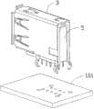
图1A是本发明第一实施方式中电连接器与电路板组合在一起的示意图。FIG. 1A is a schematic diagram of the combination of the electrical connector and the circuit board in the first embodiment of the present invention.

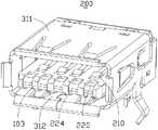
图1B是图1A中电连接器的立体组合图。FIG. 1B is a perspective assembled view of the electrical connector in FIG. 1A .

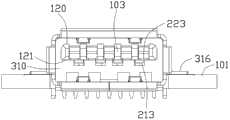
图2是图1B中电连接器的部分分解示意图。FIG. 2 is a partially exploded schematic diagram of the electrical connector in FIG. 1B .

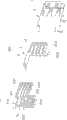
图3是图2中电连接器的立体分解示意图。FIG. 3 is an exploded perspective view of the electrical connector in FIG. 2 .

图4是图2另一角度的部分分解示意图。FIG. 4 is a partially exploded schematic diagram of another angle of FIG. 2 .

图5是图3中电连接器另一角度的立体分解示意图。FIG. 5 is an exploded perspective view of the electrical connector in FIG. 3 from another angle.

图6是图5中电连接器另一角度的立体分解示意图。FIG. 6 is an exploded perspective view of the electrical connector in FIG. 5 from another angle.

图7A是本发明第二实施方式中电连接器与电路板组合在一起的示意图。Fig. 7A is a schematic diagram of the combination of the electrical connector and the circuit board in the second embodiment of the present invention.

图7B是图7A中电连接器的立体组合图。FIG. 7B is a perspective assembled view of the electrical connector in FIG. 7A .

图8是图7B中电连接器的立体分解示意图。FIG. 8 is an exploded perspective view of the electrical connector in FIG. 7B .

图9A是本发明第三实施方式中电连接器与电路板组合在一起的示意图。Fig. 9A is a schematic diagram of the combination of the electrical connector and the circuit board in the third embodiment of the present invention.

图9B是图9A另一角度的示意图。FIG. 9B is a schematic diagram of another angle of FIG. 9A .

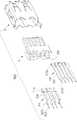
图10是图9A中电连接器的立体分解示意图。FIG. 10 is an exploded perspective view of the electrical connector in FIG. 9A .

图11A是本发明第四实施方式中电连接器与电路板组合在一起的示意图。Fig. 11A is a schematic diagram of the combination of the electrical connector and the circuit board in the fourth embodiment of the present invention.

图11B是图11A中电连接器和电路板另一角度的部分分解示意图。FIG. 11B is a partial exploded view of the electrical connector and the circuit board in FIG. 11A from another angle.

图12是图11B电连接器的部分分解示意图。FIG. 12 is a partially exploded schematic view of the electrical connector of FIG. 11B .

图13是图12中电连接器的另一部分分解示意图。FIG. 13 is another partially exploded view of the electrical connector in FIG. 12 .

图14是图13另一角度的示意图。FIG. 14 is a schematic diagram of another angle of FIG. 13 .

图15是图11B中电连接器的立体分解示意图。FIG. 15 is an exploded perspective view of the electrical connector in FIG. 11B .

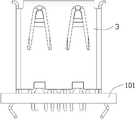
图16A是本发明第五实施方式中电连接器与电路板组合在一起的示意图。Fig. 16A is a schematic diagram of the combination of the electrical connector and the circuit board in the fifth embodiment of the present invention.

图16B是图16A另一角度的示意图。Fig. 16B is a schematic diagram of another angle of Fig. 16A.

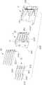
图17是图16A中电连接器的部分分解示意图。FIG. 17 is a partially exploded schematic view of the electrical connector in FIG. 16A .

图18是图16A中电连接器的立体分解示意图。FIG. 18 is an exploded perspective view of the electrical connector in FIG. 16A .

图19A是本发明第六实施方式中电连接器与电路板组合在一起的示意图。Fig. 19A is a schematic diagram of the combination of the electrical connector and the circuit board in the sixth embodiment of the present invention.

图19B是图19A另一角度的示意图。Fig. 19B is a schematic diagram of another angle of Fig. 19A.

图20是图19A中电连接器的立体分解示意图。FIG. 20 is an exploded perspective view of the electrical connector in FIG. 19A .

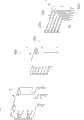
图21是和本发明电连接器相对接的第二插头的示意图。Fig. 21 is a schematic diagram of a second plug mated with the electrical connector of the present invention.

图22是和本发明电连接器相对接的USB 2.0A型标准插头的示意图。Fig. 22 is a schematic diagram of a USB 2.0A standard plug docked with the electrical connector of the present invention.

【具体实施方式】【Detailed ways】

请参照图1A至图6所示,本发明第一实施方式中的电连接器100为安装于一电路板101上的USB插座连接器,可以和USB 2.0A型标准插头8对接,也可以和第二插头7对接。USB 2.0A型插头8舌片80前端仅仅设置有四个平板状接点81,第二插头7上绝缘舌片70的尺寸和USB 2.0A型标准插头8的舌片80相同,舌片70上也设有四个平板状接点71,另外还包括位于后排的具有弹性的五个附加接点72。电连接器100包括:绝缘本体1、固定于绝缘本体1上的导电端子2、安装于绝缘本体1外围的遮蔽壳体3,该遮蔽壳体3包括前遮蔽壳体31及后遮蔽壳体32。该电连接器100还设有与电路板101相配合的安装面102及与位于前端的对接面103。1A to 6, theelectrical connector 100 in the first embodiment of the present invention is a USB receptacle connector installed on acircuit board 101, which can be docked with a USB 2.0A standard plug 8, or can be connected with The second plug 7 is butted. The front end of the USB 2.0A type plug 8tongue 80 is only provided with fourflat contacts 81, the size of the insulating tongue 70 on the second plug 7 is the same as thetongue 80 of the USB 2.0A type standard plug 8, and the tongue 70 is also There are four flat joints 71, and five additional joints 72 with elasticity in the rear row. Theelectrical connector 100 includes: an insulatingbody 1, aconductive terminal 2 fixed on the insulatingbody 1, a shieldingshell 3 installed on the periphery of the insulatingbody 1, and the shieldingshell 3 includes afront shielding shell 31 and arear shielding shell 32 . Theelectrical connector 100 also has a mountingsurface 102 matched with thecircuit board 101 and amating surface 103 at the front end.

所述前遮蔽壳体31包括顶面311、底面312、连接顶面311和底面312的一对侧面313,顶面311和底面312以及侧面313之间形成一收容空间310,绝缘本体1包括有主体部11以及自主体部11向前延伸而成的相对较薄的舌板12,舌板12的尺寸和USB 2.0A型插座连接器的舌板尺寸相同,从而,制造本发明电连接器100时,可以重复利用USB 2.0A型插座连接器的部分模具,节省成本。舌板12位于收容空间310内,舌板12与前遮蔽壳体31的两侧面313、顶面311和底面312之间均相隔一定距离,本实施方式中,舌板12到前遮蔽壳体31顶面311比到底面312的距离更小。主体部11底部向下延伸形成有若干与电路板101抵接的垫脚13,所述安装面102为垫脚的底表面。Thefront shielding shell 31 includes atop surface 311, abottom surface 312, a pair of side surfaces 313 connecting thetop surface 311 and thebottom surface 312, a receivingspace 310 is formed between thetop surface 311, thebottom surface 312 and the side surfaces 313, and the insulatingbody 1 includes Themain body 11 and the relativelythin tongue plate 12 extending forward from themain body 11, thetongue plate 12 has the same size as the tongue plate of the USB 2.0A receptacle connector, thereby making theelectrical connector 100 of the present invention , you can reuse part of the mold for the USB 2.0A receptacle connector to save costs. Thetongue plate 12 is located in the receivingspace 310, and there is a certain distance between thetongue plate 12 and the twoside surfaces 313, thetop surface 311 and thebottom surface 312 of thefront shielding shell 31. In this embodiment, thetongue plate 12 reaches thefront shielding shell 31 Thetop surface 311 has a smaller distance than thebottom surface 312 . The bottom of themain body 11 extends downwards to form a plurality offeet 13 abutting against thecircuit board 101 , and the mountingsurface 102 is the bottom surface of the feet.

所述导电端子2整体弯折成直角形状,包括有第一端子组21及第二端子组22,本实施方式中,第一端子组21和USB 2.0A型插座连接器的四根USB插座端子相同,即依次排列为电源端子217、第一对差分信号端子218(即负信号端子和正信号端子)、第一接地端子219。第一端子组21包括若干用以和USB 2.0A型插头8及第二插头7上的平板状接点81、71相接触的第一接触部210、与第一接触部210相连的用以与绝缘本体1固定的第一固持部211、自第一固持部211一端弯折延伸而成的用以与电路板101相连的第一焊接部212。其中,第一接触部210设置为圆弧状弹性结构。舌板12具有抵接面121及与抵接面121相对的配合面120,在本实施方式中,分别为舌板12下表面和上表面,第一接触部210向下延伸而凸伸出舌板12抵接面121,从而,第一接触部210与对接插头7、8相接触的第一接触点213位于舌板12抵接面121的下方。舌板12的抵接面121凹设有四个并排设置的用以收容第一端子组21的第一收容槽1211。所述第二焊接部212卡扣于绝缘本体1主体部11上设置的纵向延伸的第一固定槽111,并且向下延伸出主体部11,用以和电路板101连接。Theconductive terminal 2 is bent into a right-angle shape as a whole, including a firstterminal group 21 and a secondterminal group 22. In this embodiment, the firstterminal group 21 and the four USB socket terminals of the USB 2.0A socket connector The same, that is, the power supply terminal 217 , the first pair of differential signal terminals 218 (that is, the negative signal terminal and the positive signal terminal), and the first ground terminal 219 are arranged in sequence. The firstterminal group 21 includes a plurality offirst contact portions 210 for contacting with theplanar contacts 81, 71 on the USB 2.0A type plug 8 and the second plug 7, connected with thefirst contact portion 210 for insulating Thefirst holding portion 211 fixed to thebody 1 , and thefirst welding portion 212 bent and extended from one end of thefirst holding portion 211 are used for connecting with thecircuit board 101 . Wherein, thefirst contact portion 210 is configured as an arc-shaped elastic structure. Thetongue plate 12 has anabutment surface 121 and amating surface 120 opposite to theabutment surface 121. In this embodiment, they are the lower surface and the upper surface of thetongue plate 12 respectively. Thefirst contact portion 210 extends downwards to protrude from the tongue Theplate 12 abuts against thesurface 121 , so that thefirst contact point 213 where thefirst contact portion 210 contacts the mating plugs 7 , 8 is located below the abuttingsurface 121 of thetongue plate 12 . Theabutting surface 121 of thetongue plate 12 is recessed with fourfirst receiving grooves 1211 arranged side by side for receiving the firstterminal group 21 . Thesecond welding portion 212 is snapped into the longitudinally extending first fixing groove 111 provided on themain body 11 of the insulatingbody 1 , and extends downwards out of themain body 11 for connecting with thecircuit board 101 .

第二端子组22是在USB 2.0A型插座连接器的舌板上附加的五根端子,用以提高信号传输速度,包括第二对差分信号端子225及第三对差分信号端子227以及位于第二对及第三对差分信号端子之间的第二接地端子226,第二接地端子226用以降低第二对及第三对第二差分信号端子225、227之间的串绕。第二端子组22仅仅用以和第二插头7上位于平板状接点71后方的具有弹性的附加接点72接触。第二端子组22包括若干第二接触部220、与第二接触部220相连的用以与绝缘本体1固定的第二固持部221、自第二固持部221一端弯折延伸而成的用以与电路板101相连的第二焊接部222。其中,第二接触部220设置为平板状结构,第二接触部220上的与第二插头7接触的第二接触点223位于舌板12抵接面121的上方,第二接触点223和第一接触点213分别位于舌板12抵接面121的两侧。第一接触部210和第二接触部220沿舌板12的厚度方向位于不同高度上,USB 2.0A型插头8和第二插头7上的平板状接点81、71只能接触到与其对应的具有弹性的第一接触部210,而不会接触到收容于舌板12内的平板状第二接触部220,从而,避免产生混乱信号。Thesecond terminal group 22 is five additional terminals on the tongue plate of the USB 2.0A socket connector, in order to improve the signal transmission speed, including the second pair of differential signal terminals 225 and the third pair of differential signal terminals 227 and the second pair of differential signal terminals 227 and the second pair of differential signal terminals 227. The second ground terminal 226 between the second pair and the third pair of differential signal terminals, the second ground terminal 226 is used to reduce cross-winding between the second pair and the third pair of second differential signal terminals 225 , 227 . Thesecond terminal group 22 is only used to contact the elastic additional contact 72 on the second plug 7 behind the flat contact 71 . Thesecond terminal group 22 includes a plurality ofsecond contact parts 220, asecond holding part 221 connected to thesecond contact parts 220 for fixing with the insulatinghousing 1, and asecond holding part 221 bent and extended from one end of thesecond holding part 221 for Thesecond soldering portion 222 connected with thecircuit board 101 . Wherein, thesecond contact portion 220 is arranged as a flat plate structure, and thesecond contact point 223 on thesecond contact portion 220 which is in contact with the second plug 7 is located above thecontact surface 121 of thetongue plate 12. Thesecond contact point 223 and the second contact point 223 Acontact point 213 is respectively located on two sides of theabutting surface 121 of thetongue plate 12 . Thefirst contact portion 210 and thesecond contact portion 220 are located at different heights along the thickness direction of thetongue plate 12, and the flat contact points 81, 71 on the USB 2.0A type plug 8 and the second plug 7 can only touch the corresponding ones with The elasticfirst contact portion 210 will not contact the planarsecond contact portion 220 accommodated in thetongue plate 12 , thereby avoiding the generation of confusing signals.

舌板12的配合面120凹设有用以收容第二固持部221的五个第三收容槽1201。第二接触部220位于第二固持部221的下方,第二接触部220与第二固持部221之间连接有转接部224,第二接触部220和第二固持部221分别自转接部224的上下端向后延伸而成。舌板12抵接面121凹设有用以收容第二接触部220的第二收容槽1212,该第二收容槽1212并排设置而位于第一收容槽1211的前方。舌板12的前端向后凹设有上下贯通舌板12抵接面121和配合面120的用以收容转接部224的凹部122,凹部122连通第三收容槽1201及第二收容槽1212。第二焊接部222安装于绝缘本体1主体部11上,并且向下延伸出主体部11。第二固持部221位于舌板12的上半部分,第一接触部210和第二接触部220均位于舌板12的下半部分即位于舌板12的同一侧,第一接触部210位于第二接触部220的后方,充分利用了USB 2.0A型插座连接器中舌板的有限尺寸来安装第一端子组21及第二端子组22。Themating surface 120 of thetongue plate 12 is recessed with fivethird receiving grooves 1201 for receiving thesecond holding portion 221 . Thesecond contact portion 220 is located below thesecond holding portion 221, and atransfer portion 224 is connected between thesecond contact portion 220 and thesecond holding portion 221, and thesecond contact portion 220 and thesecond holding portion 221 are connected from the transfer portion The upper and lower ends of 224 extend backward. Theabutting surface 121 of thetongue plate 12 is recessed with asecond receiving groove 1212 for receiving thesecond contact portion 220 , and thesecond receiving grooves 1212 are arranged side by side and located in front of thefirst receiving groove 1211 . The front end of thetongue plate 12 is recessed backward to define arecess 122 for accommodating the connectingportion 224 through theabutting surface 121 and themating surface 120 of thetongue plate 12 up and down. Therecess 122 communicates with thethird receiving groove 1201 and thesecond receiving groove 1212 . Thesecond welding portion 222 is mounted on themain body 11 of the insulatinghousing 1 and extends downwards out of themain body 11 . Thesecond retaining portion 221 is located on the upper half of thetongue plate 12, thefirst contact portion 210 and thesecond contact portion 220 are both located on the lower half of thetongue plate 12, that is, on the same side of thetongue plate 12, and thefirst contact portion 210 is located on the second half of thetongue plate 12. The rear of thesecond contact portion 220 makes full use of the limited size of the tongue plate in the USB 2.0A receptacle connector to install the firstterminal group 21 and thesecond terminal group 22.

前遮蔽壳体3顶面311、底面312及侧面313上设置有若干延伸入收容空间310的用以抵持对接插头的弹片315及位于最前端的朝外倾斜延伸的导引片314,该导引片314引导对接插头插入收容空间310内。前遮蔽壳体3侧面313向下延伸有固定于电路板101上的焊接脚316。前遮蔽壳体3顶面311后端设有固持孔317,用以和后遮蔽壳体32上端的固持片321相卡扣。后遮蔽壳体32两侧面上设有凸点322,用以和前遮蔽壳体31两侧面313上的凹孔318相扣持,从而将后遮蔽壳体32组装至前遮蔽壳体31上,并且包覆绝缘本体1和导电端子2。Thetop surface 311, thebottom surface 312 and theside surface 313 of thefront shielding shell 3 are provided with a number ofelastic pieces 315 extending into the receivingspace 310 to resist the docking plug and aguide piece 314 extending obliquely outward at the front end. Thelead piece 314 guides the mating plug to be inserted into the receivingspace 310 . Asoldering pin 316 fixed on thecircuit board 101 extends downward from theside 313 of thefront shielding case 3 . The rear end of thetop surface 311 of thefront shielding shell 3 is provided with a retaining hole 317 for buckling with the retaining piece 321 on the upper end of therear shielding shell 32 . Protrusions 322 are provided on both sides of therear shielding shell 32 to be locked with the concave holes 318 on the twosides 313 of thefront shielding shell 31, so that therear shielding shell 32 is assembled to thefront shielding shell 31. And cover the insulatingbody 1 and theconductive terminal 2 .

绝缘本体1主体部11后端向前凹设有一容置空间113,一定位板4组装至容置空间113内,设有五个上下贯通的定位孔41,第二焊接部222插入定位孔41内并且向下延伸出定位板4,从而,导电端子2第二焊接部222得到良好的定位。定位板4两侧设有一呈三角形的卡臂42,用以和容置空间113内设置的挡板114相扣持,从而将定位板4牢靠的固定在主体部11上。The rear end of themain body part 11 of the insulatingbody 1 is recessed forward with a receivingspace 113, and apositioning plate 4 is assembled into the receivingspace 113, and fivepositioning holes 41 penetrating up and down are provided, and thesecond welding part 222 is inserted into the positioning holes 41 Thepositioning plate 4 extends inside and downwards, so that thesecond welding portion 222 of theconductive terminal 2 is well positioned. Two sides of thepositioning plate 4 are provided with atriangular locking arm 42 for interlocking with the baffle 114 provided in theaccommodating space 113 , so as to securely fix thepositioning plate 4 on themain body 11 .

请参阅图7A至图8所示,本发明第二实施方式中的电连接器200与第一实施方式中的电连接器100相似,其与第一实施方式不同之处在于:舌板12到前遮蔽壳体31的顶面311的距离比到底面312的距离更大,所述第一收容槽1211和第二收容槽1212设置于舌板12的上半部分,相应的,第三收容槽1201设置于舌板12的下半部分,舌板12抵接面121及与抵接面121相对的配合面120分别为舌板12上表面和下表面。第一接触部210和第二接触部220均位于舌板12的上半部分。Please refer to FIG. 7A to FIG. 8 , theelectrical connector 200 in the second embodiment of the present invention is similar to theelectrical connector 100 in the first embodiment, and it differs from the first embodiment in that thetongue plate 12 to The distance between thetop surface 311 of thefront shielding shell 31 is greater than the distance between thebottom surface 312, and thefirst receiving groove 1211 and thesecond receiving groove 1212 are arranged on the upper half of thetongue plate 12, and correspondingly, thethird receiving groove 1201 is arranged on the lower half of thetongue plate 12 , thecontact surface 121 of thetongue plate 12 and themating surface 120 opposite to thecontact surface 121 are the upper surface and the lower surface of thetongue plate 12 respectively. Both thefirst contact portion 210 and thesecond contact portion 220 are located on the upper half of thetongue plate 12 .

请参阅图9A至图10所示,本发明第三实施方式中的电连接器300与第一实施方式中的电连接器100相似,其与第一实施方式不同之处在于:电连接器300安装于前端具有开口104的电路板101上,前遮蔽壳体31的前端焊接脚316是自前遮蔽壳体31侧面313的中部朝外水平延伸而成。电连接器300的安装面102为前端焊接脚316的下表面,且位于前遮蔽壳体31底面312的上方。前遮蔽壳体31底面312及部分侧面313是收容于电路板101开口104内,如此设置,可以降低电连接器300和电路板101的整体高度。Please refer to FIG. 9A to FIG. 10 , theelectrical connector 300 in the third embodiment of the present invention is similar to theelectrical connector 100 in the first embodiment, and it differs from the first embodiment in that theelectrical connector 300 Installed on thecircuit board 101 with theopening 104 at the front end, thefront soldering pin 316 of thefront shielding shell 31 is horizontally extended outward from the middle of theside 313 of thefront shielding shell 31 . The mountingsurface 102 of theelectrical connector 300 is the lower surface of thefront soldering pin 316 and is located above thebottom surface 312 of thefront shielding shell 31 . Thebottom surface 312 and part of theside surface 313 of thefront shielding shell 31 are accommodated in theopening 104 of thecircuit board 101 , so that the overall height of theelectrical connector 300 and thecircuit board 101 can be reduced.

主体部11的下端向前延伸形成有收容于电路板101开口104内的支撑板115,该支撑板115与舌板12大致平行,前遮蔽壳体31底面312向后延伸有卡扣部319,该卡扣部319固定于主体部11上,支撑板115支撑前遮蔽壳体31底面312的后部分。The lower end of themain body 11 extends forward to form asupport plate 115 accommodated in theopening 104 of thecircuit board 101 , thesupport plate 115 is roughly parallel to thetongue plate 12 , and thebottom surface 312 of thefront shielding shell 31 extends backward with abuckle portion 319 . Thebuckle portion 319 is fixed on themain body portion 11 , and thesupport plate 115 supports the rear portion of thebottom surface 312 of thefront shielding case 31 .

请参阅图11A至图15所示,本发明第四实施方式中的电连接器400与第一实施方式中的电连接器100相似,其与第一实施方式不同之处在于:电连接器400的舌板12垂直于安装面102,舌板12抵接面121及与抵接面121相对的配合面120,在本实施方式中,分别为舌板12左侧面和右侧面,第一接触部210沿上下方向依次排列,且相互隔开。第二接触部220也沿上下方向依次排列,且相互隔开。第一端子组21和第二端子组22之间夹持有一固持板5。绝缘本体1后部还设有一开口朝后的凹室116,用以收容固持板5、第一端子组21和第二端子组22。该固持板5的两侧分别凸设有若干间隔设置的纵向凸条51,第一焊接部212及第二焊接部222均固定于相邻凸条51之间,第一端子组21的第一焊接部212与第一固持部211之间还设有向前延伸,然后横向延伸而成的弯折部214,该弯折部214后端抵靠在纵向凸条51的顶端,弯折部214横向部分贴靠在固持板5的前表面上。Please refer to FIG. 11A to FIG. 15 , theelectrical connector 400 in the fourth embodiment of the present invention is similar to theelectrical connector 100 in the first embodiment, and it differs from the first embodiment in that theelectrical connector 400 Thetongue plate 12 is perpendicular to the mountingsurface 102, theabutment surface 121 of thetongue plate 12 and themating surface 120 opposite to theabutment surface 121, in this embodiment, are respectively the left side and the right side of thetongue plate 12, the first Thecontact portions 210 are arranged in sequence along the vertical direction and are spaced apart from each other. Thesecond contact portions 220 are also arranged in sequence along the vertical direction and are spaced apart from each other. A holdingplate 5 is clamped between the firstterminal group 21 and thesecond terminal group 22 . There is also analcove 116 at the rear of the insulatingbody 1 , which is used for accommodating the holdingplate 5 , the firstterminal group 21 and thesecond terminal group 22 . Both sides of the holdingplate 5 are protrudingly provided with a plurality of longitudinalconvex strips 51 arranged at intervals, and thefirst welding part 212 and thesecond welding part 222 are fixed between the adjacent convex strips 51. The firstterminal group 21 Between thewelding part 212 and the first holdingpart 211, there is also a bendingpart 214 that extends forward and then extends laterally. The transverse portion bears against the front face of the holdingplate 5 .

请参阅图16A至图18所示,本发明第五实施方式中的电连接器500与第一实施方式中的电连接器100相似,其与第一实施方式不同之处在于:收容空间310的开口(即插接口)朝上,舌板12垂直于安装面102,第一接触部210及第二接触部220均位于舌板12的右侧。第一固持部211与第一焊接部212大致平行,中间连接有折弯部215。第二固持部221和第二焊接部222在竖直方向对齐。Please refer to FIG. 16A to FIG. 18 , theelectrical connector 500 in the fifth embodiment of the present invention is similar to theelectrical connector 100 in the first embodiment, and it differs from the first embodiment in that thestorage space 310 The opening (that is, the plugging interface) faces upward, thetongue plate 12 is perpendicular to theinstallation surface 102 , and thefirst contact portion 210 and thesecond contact portion 220 are located on the right side of thetongue plate 12 . Thefirst holding portion 211 is substantially parallel to thefirst welding portion 212 , and abent portion 215 is connected therebetween. Thesecond holding portion 221 and thesecond welding portion 222 are vertically aligned.

请参阅图19A至图20所示,本发明第六实施方式中的电连接器600与第一实施方式中的电连接器100相似,其与第一实施方式不同之处在于:收容空间310的开口朝上,舌板12垂直于安装面102,第一接触部210及第二接触部220均位于舌板12的右侧。第一固持部211与第一焊接部212大致平行,中间连接有转折部216。第二焊接部222自第二固持部221末端倾斜延伸而成。安装面102和对接面103之间不垂直,也不平行,也就是说,安装面102倾斜于对接面103。Please refer to FIG. 19A to FIG. 20 , theelectrical connector 600 in the sixth embodiment of the present invention is similar to theelectrical connector 100 in the first embodiment. The opening faces upward, thetongue plate 12 is perpendicular to theinstallation surface 102 , and thefirst contact portion 210 and thesecond contact portion 220 are located on the right side of thetongue plate 12 . Thefirst holding portion 211 is substantially parallel to thefirst welding portion 212 , and a turning portion 216 is connected therebetween. Thesecond welding portion 222 extends obliquely from the end of thesecond holding portion 221 . Theinstallation surface 102 and themating surface 103 are neither perpendicular nor parallel, that is to say, theinstallation surface 102 is inclined to themating surface 103 .

Claims (13)

Translated fromChinese
1.一种电连接器,其设有可与电路板相配合的安装面以及可与对接插头相对接的对接面,所述电连接器包括绝缘本体、设于绝缘本体上的导电端子以及包覆绝缘本体的遮蔽壳体,所述遮蔽壳体设有收容空间,所述绝缘本体设有主体部以及延伸入收容空间内的舌板,其特征在于:所述导电端子包括第一端子组以及第二端子组,所述第一端子组包括电源端子、第一接地端子以及位于电源端子与第一接地端子之间的第一对差分信号端子,所述第一端子组中的端子包括设于舌板上的弹性第一接触部以及第一焊接部,所述第二端子组包括第二对差分信号端子、第三对差分信号端子以及位于第二对及第三对差分信号端子之间的第二接地端子,所述第二端子组中的端子包括设于舌板上的平板状第二接触部以及第二焊接部,所述第一接触部与第二接触部均位于舌板的同一侧,且所述第二接触部相较第一接触部更靠近电连接器的对接面。1. An electrical connector, which is provided with a mounting surface that can be matched with a circuit board and a docking surface that can be docked with a butt plug, and the electrical connector includes an insulating body, a conductive terminal that is located on the insulating body, and a package A shielding shell covering the insulating body, the shielding shell is provided with a receiving space, and the insulating body is provided with a main body and a tongue plate extending into the receiving space, wherein the conductive terminal includes a first terminal group and The second terminal group, the first terminal group includes a power terminal, a first ground terminal, and a first pair of differential signal terminals located between the power terminal and the first ground terminal, and the terminals in the first terminal group include terminals located at The elastic first contact portion and the first welding portion on the tongue plate, the second terminal group includes a second pair of differential signal terminals, a third pair of differential signal terminals, and a terminal between the second pair and the third pair of differential signal terminals The second ground terminal, the terminals in the second terminal group include a flat second contact portion and a second welding portion arranged on the tongue plate, the first contact portion and the second contact portion are both located on the same side of the tongue plate side, and the second contact portion is closer to the mating surface of the electrical connector than the first contact portion.2.如权利要求1所述的电连接器,其特征在于:所述舌板设有抵接面以及与抵接面相对的配合面,所述抵接面凹设有并排设置的第一收容槽以及相较第一收容槽更靠近所述对接面的第二收容槽,所述第一接触部设在第一收容槽内并设有与对接插头接触的第一接触点,所述第二接触部设在第二收容槽内并设有与对接插头接触的第二接触点,所述第一接触点与第二接触点分别位于所述抵接面的两侧。2. The electrical connector according to claim 1, wherein the tongue plate is provided with an abutment surface and a mating surface opposite to the abutment surface, and the abutment surface is concavely provided with first accommodating surfaces arranged side by side. groove and a second receiving groove that is closer to the mating surface than the first receiving groove, the first contact portion is set in the first receiving groove and is provided with a first contact point that is in contact with the docking plug, and the second The contact part is arranged in the second receiving groove and has a second contact point to contact with the mating plug, and the first contact point and the second contact point are respectively located on two sides of the abutting surface.3.如权利要求2所述的电连接器,其特征在于:所述第二端子组中的端子还包括沿舌板厚度方向与第二接触部位于不同高度的第二固持部。3 . The electrical connector according to claim 2 , wherein the terminals in the second terminal group further comprise a second holding portion located at a different height from the second contact portion along the thickness direction of the tongue plate. 4 .4.如权利要求3所述的电连接器,其特征在于:所述舌板的配合面凹设有用以收容所述第二固持部的第三收容槽。4 . The electrical connector as claimed in claim 3 , wherein a third receiving groove for receiving the second holding portion is recessed on the mating surface of the tongue plate.5.如权利要求1所述的电连接器,其特征在于:该电连接器还包括组装至绝缘本体的定位板,所述定位板设有供第二焊接部插入的定位孔。5 . The electrical connector as claimed in claim 1 , further comprising a positioning plate assembled to the insulating body, and the positioning plate is provided with a positioning hole for inserting the second welding portion. 6 .6.如权利要求1所述的电连接器,其特征在于:所述遮蔽壳体包括形成所述收容空间的顶面、底面以及连接所述顶面和底面的一对侧面。6. The electrical connector according to claim 1, wherein the shielding shell comprises a top surface and a bottom surface forming the receiving space, and a pair of side surfaces connecting the top surface and the bottom surface.7.如权利要求6所述的电连接器,其特征在于:所述主体部延伸形成有支撑所述遮蔽壳体底面的支撑板,所述遮蔽壳体的底面延伸有固定于主体部上的卡扣部。7. The electrical connector according to claim 6, wherein the main body is extended to form a support plate supporting the bottom surface of the shielding housing, and the bottom surface of the shielding housing is extended with a support plate fixed on the main body. buckle department.8.如权利要求6所述的电连接器,其特征在于:所述对接面与安装面相互垂直,所述第一、第二焊接部向下延伸出遮蔽壳体的底面,所述舌板到遮蔽壳体的顶面距离比所述舌板到遮蔽壳体底面的距离更大,所述第一接触部和第二接触部均位于舌板的上方。8. The electrical connector according to claim 6, wherein the butt joint surface and the mounting surface are perpendicular to each other, the first and second welding parts extend downward to the bottom surface of the shielding housing, and the tongue plate The distance from the top surface of the shielding case is greater than the distance from the tongue plate to the bottom surface of the shielding case, and both the first contact portion and the second contact portion are located above the tongue plate.9.如权利要求6所述的电连接器,其特征在于:所述对接面与安装面相互垂直,所述安装面沿高度方向位于所述遮蔽壳体的顶面与底面之间。9 . The electrical connector according to claim 6 , wherein the mating surface and the installation surface are perpendicular to each other, and the installation surface is located between the top surface and the bottom surface of the shielding shell along the height direction.10.如权利要求1所述的电连接器,其特征在于:所述对接面与安装面相互垂直,所述舌板沿前后方向延伸且垂直于安装面,所述第一接触部与第二接触部均沿上下方向排列于舌板的一侧。10. The electrical connector according to claim 1, wherein the butt surface and the mounting surface are perpendicular to each other, the tongue plate extends along the front and rear directions and is perpendicular to the mounting surface, and the first contact portion and the second The contact parts are all arranged on one side of the tongue plate along the up and down direction.11.如权利要求10所述的电连接器,其特征在于:该电连接器还包括组装至绝缘本体的固持板,所述固持板夹持在第一端子组与第二端子组之间,所述绝缘本体的后部设有一开口朝后以收容固持板的凹室,所述固持板的两侧分别凸设有若干间隔设置的纵向凸条,所述第一焊接部及第二焊接部均固定于相邻的两凸条之间。11. The electrical connector according to claim 10, characterized in that: the electrical connector further comprises a holding plate assembled to the insulating body, the holding plate is clamped between the first terminal group and the second terminal group, The rear part of the insulating body is provided with an alcove with an opening facing backward to accommodate the holding plate, and the two sides of the holding plate are respectively protruded with a number of longitudinal ribs arranged at intervals. The first welding part and the second welding part Both are fixed between two adjacent convex strips.12.如权利要求1所述的电连接器,其特征在于:所述舌板沿上下方向延伸,所述对接面与安装面之间相互平行或相互倾斜。12 . The electrical connector according to claim 1 , wherein the tongue plate extends in an up-down direction, and the mating surface and the mounting surface are parallel to each other or inclined to each other. 13 .13.如权利要求12所述的电连接器,其特征在于:所述第一端子组中的端子还设有第一固持部以及连接第一固持部与第一焊接部的折弯部,所述第一固持部与第一焊接部相互平行。13. The electrical connector according to claim 12, wherein the terminals in the first terminal group are further provided with a first holding portion and a bending portion connecting the first holding portion and the first welding portion, so The first holding portion and the first welding portion are parallel to each other.
CN 2011101482292007-08-102007-08-10Electric connectorActiveCN102324642B (en)

Priority Applications (1)

Application NumberPriority DateFiling DateTitle
CN 201110148229CN102324642B (en)2007-08-102007-08-10Electric connector

Applications Claiming Priority (1)

Application NumberPriority DateFiling DateTitle
CN 201110148229CN102324642B (en)2007-08-102007-08-10Electric connector

Related Parent Applications (1)

Application NumberTitlePriority DateFiling Date
CN2007100259340ADivisionCN101364694B (en)2007-08-102007-08-10 electrical connector

Publications (2)

Publication NumberPublication Date
CN102324642Atrue CN102324642A (en)2012-01-18
CN102324642B CN102324642B (en)2013-05-08

Family

ID=45452339

Family Applications (1)

Application NumberTitlePriority DateFiling Date
CN 201110148229ActiveCN102324642B (en)2007-08-102007-08-10Electric connector

Country Status (1)

CountryLink
CN (1)CN102324642B (en)

Cited By (3)

* Cited by examiner, † Cited by third party
Publication numberPriority datePublication dateAssigneeTitle
CN104733882A (en)*2015-03-092015-06-24连展科技(深圳)有限公司Stand type socket electric connector
CN108232676A (en)*2016-12-212018-06-29富士康(昆山)电脑接插件有限公司Electric connector
US10553994B2 (en)2016-12-212020-02-04Foxconn Interconnect Technology LimitedElectrical connector having separate front and rear shielding shells

Citations (5)

* Cited by examiner, † Cited by third party
Publication numberPriority datePublication dateAssigneeTitle
US6554646B1 (en)*1998-12-142003-04-29Berg Electronics Group, Inc.Electrical connector assembly
CN1421059A (en)*2000-03-312003-05-28莫莱克斯公司Channel isolation shield
CN2587083Y (en)*2002-11-132003-11-19富士康(昆山)电脑接插件有限公司Cable connector assembly
JP2005503656A (en)*2001-08-012005-02-03モレックス インコーポレーテッド Impedance adjusted connector
US20050118876A1 (en)*2001-09-252005-06-02Toshihiro NiitsuConnector for high-rate transmission

Patent Citations (5)

* Cited by examiner, † Cited by third party
Publication numberPriority datePublication dateAssigneeTitle
US6554646B1 (en)*1998-12-142003-04-29Berg Electronics Group, Inc.Electrical connector assembly
CN1421059A (en)*2000-03-312003-05-28莫莱克斯公司Channel isolation shield
JP2005503656A (en)*2001-08-012005-02-03モレックス インコーポレーテッド Impedance adjusted connector
US20050118876A1 (en)*2001-09-252005-06-02Toshihiro NiitsuConnector for high-rate transmission
CN2587083Y (en)*2002-11-132003-11-19富士康(昆山)电脑接插件有限公司Cable connector assembly

Cited By (4)

* Cited by examiner, † Cited by third party
Publication numberPriority datePublication dateAssigneeTitle
CN104733882A (en)*2015-03-092015-06-24连展科技(深圳)有限公司Stand type socket electric connector
CN104733882B (en)*2015-03-092024-05-03连展科技(深圳)有限公司Vertical socket electric connector
CN108232676A (en)*2016-12-212018-06-29富士康(昆山)电脑接插件有限公司Electric connector
US10553994B2 (en)2016-12-212020-02-04Foxconn Interconnect Technology LimitedElectrical connector having separate front and rear shielding shells

Also Published As

Publication numberPublication date
CN102324642B (en)2013-05-08

Similar Documents

PublicationPublication DateTitle
CN101364694B (en) electrical connector
CN101562290B (en)Flash memory device
CN101453088B (en) electrical connector
CN102394408B (en)Cable connecting assembly
CN201113076Y (en) socket electrical connector
CN201097426Y (en) socket electrical connector
CN201204275Y (en) electrical connector
CN101364692B (en)Electric connector for socket
CN102437482B (en)Electrical connector
CN101740951B (en)Electric connector
CN201252288Y (en)Electrical connector
CN201430309Y (en)Electric connector
CN202150590U (en)Cable plug connector
CN201303172Y (en)Electric connector
CN101728663A (en)Cable connector assembly
CN101771226A (en) electrical connector
CN201097428Y (en)Stacked electric connector
CN202159800U (en)Cable plug connector, board end socket connector and connector assembly
CN201708308U (en)Electric connector
CN103972730B (en)Electric connector
CN201708312U (en)Connector for electronic card
CN102324642A (en) electrical connector
CN201097427Y (en) electrical connector
CN201774000U (en) Terminal and electrical connector using the terminal
CN101834357B (en)Electrical connector

Legal Events

DateCodeTitleDescription
C06Publication
PB01Publication
C10Entry into substantive examination
SE01Entry into force of request for substantive examination
C14Grant of patent or utility model
GR01Patent grant

[8]ページ先頭

©2009-2025 Movatter.jp