CN102319457B - Self-damping vibration-elimination magnetic levitation artificial heart blood pump rotor and preparation method thereof - Google Patents
Self-damping vibration-elimination magnetic levitation artificial heart blood pump rotor and preparation method thereofDownload PDFInfo
- Publication number
- CN102319457B CN102319457BCN201110245417.0ACN201110245417ACN102319457BCN 102319457 BCN102319457 BCN 102319457BCN 201110245417 ACN201110245417 ACN 201110245417ACN 102319457 BCN102319457 BCN 102319457B
- Authority
- CN
- China
- Prior art keywords
- damping
- rotor
- blood pump
- rotor body
- self
- Prior art date
- Legal status (The legal status is an assumption and is not a legal conclusion. Google has not performed a legal analysis and makes no representation as to the accuracy of the status listed.)
- Active
Links
- 238000013016dampingMethods0.000titleclaimsabstractdescription167
- 239000008280bloodSubstances0.000titleclaimsabstractdescription34
- 210000004369bloodAnatomy0.000titleclaimsabstractdescription34
- 238000002360preparation methodMethods0.000titleclaimsabstractdescription6
- 238000005339levitationMethods0.000titleabstractdescription6
- 238000003379elimination reactionMethods0.000titleabstract2
- 239000007788liquidSubstances0.000claimsabstractdescription7
- 239000012530fluidSubstances0.000claimsdescription41
- 239000000725suspensionSubstances0.000claimsdescription33
- 238000000034methodMethods0.000claimsdescription7
- 230000002093peripheral effectEffects0.000claimsdescription5
- 230000008569processEffects0.000claimsdescription5
- 238000012545processingMethods0.000claimsdescription4
- 230000003746surface roughnessEffects0.000claimsdescription4
- 239000010721machine oilSubstances0.000claimsdescription3
- XLYOFNOQVPJJNP-UHFFFAOYSA-NwaterSubstancesOXLYOFNOQVPJJNP-UHFFFAOYSA-N0.000claimsdescription3
- 238000003466weldingMethods0.000claimsdescription2
- 230000009286beneficial effectEffects0.000abstractdescription2
- 230000008030eliminationEffects0.000abstract1
- 238000007790scrapingMethods0.000abstract1
- 230000000694effectsEffects0.000description5
- 238000005516engineering processMethods0.000description5
- 238000011161developmentMethods0.000description3
- 239000011435rockSubstances0.000description3
- 230000008859changeEffects0.000description2
- 238000010438heat treatmentMethods0.000description2
- 230000005389magnetismEffects0.000description2
- 239000007787solidSubstances0.000description2
- 230000009471actionEffects0.000description1
- 238000013459approachMethods0.000description1
- 230000002238attenuated effectEffects0.000description1
- 230000006399behaviorEffects0.000description1
- 230000017531blood circulationEffects0.000description1
- 230000008878couplingEffects0.000description1
- 238000010168coupling processMethods0.000description1
- 238000005859coupling reactionMethods0.000description1
- 238000013524data verificationMethods0.000description1
- 238000009826distributionMethods0.000description1
- 230000005764inhibitory processEffects0.000description1
- 238000004519manufacturing processMethods0.000description1
- 238000005457optimizationMethods0.000description1
- 210000000056organAnatomy0.000description1
- 230000009466transformationEffects0.000description1
Images
Landscapes
- External Artificial Organs (AREA)
Abstract
Description


| Rotor height | 14.5 | Millimeter |
| Root diameter | 25 | Millimeter |
| Rotor quality | 100 | Gram |
| Inclined rigidity | 5.6956 | N-m/rad |
| Inclination damping | 7.25e-6 | N-m-s/rad |
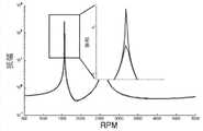
| Precession critical speed | 1566 | RPM |
Claims (9)


Priority Applications (1)
| Application Number | Priority Date | Filing Date | Title |
|---|---|---|---|
| CN201110245417.0ACN102319457B (en) | 2011-08-25 | 2011-08-25 | Self-damping vibration-elimination magnetic levitation artificial heart blood pump rotor and preparation method thereof |
Applications Claiming Priority (1)
| Application Number | Priority Date | Filing Date | Title |
|---|---|---|---|
| CN201110245417.0ACN102319457B (en) | 2011-08-25 | 2011-08-25 | Self-damping vibration-elimination magnetic levitation artificial heart blood pump rotor and preparation method thereof |
Publications (2)
| Publication Number | Publication Date |
|---|---|
| CN102319457A CN102319457A (en) | 2012-01-18 |
| CN102319457Btrue CN102319457B (en) | 2014-01-29 |
Family
ID=45447369
Family Applications (1)
| Application Number | Title | Priority Date | Filing Date |
|---|---|---|---|
| CN201110245417.0AActiveCN102319457B (en) | 2011-08-25 | 2011-08-25 | Self-damping vibration-elimination magnetic levitation artificial heart blood pump rotor and preparation method thereof |
Country Status (1)
| Country | Link |
|---|---|
| CN (1) | CN102319457B (en) |
Cited By (11)
| Publication number | Priority date | Publication date | Assignee | Title |
|---|---|---|---|---|
| US10722631B2 (en) | 2018-02-01 | 2020-07-28 | Shifamed Holdings, Llc | Intravascular blood pumps and methods of use and manufacture |
| US11185677B2 (en) | 2017-06-07 | 2021-11-30 | Shifamed Holdings, Llc | Intravascular fluid movement devices, systems, and methods of use |
| US11511103B2 (en) | 2017-11-13 | 2022-11-29 | Shifamed Holdings, Llc | Intravascular fluid movement devices, systems, and methods of use |
| US11654275B2 (en) | 2019-07-22 | 2023-05-23 | Shifamed Holdings, Llc | Intravascular blood pumps with struts and methods of use and manufacture |
| US11724089B2 (en) | 2019-09-25 | 2023-08-15 | Shifamed Holdings, Llc | Intravascular blood pump systems and methods of use and control thereof |
| US11964145B2 (en) | 2019-07-12 | 2024-04-23 | Shifamed Holdings, Llc | Intravascular blood pumps and methods of manufacture and use |
| US12102815B2 (en) | 2019-09-25 | 2024-10-01 | Shifamed Holdings, Llc | Catheter blood pumps and collapsible pump housings |
| US12121713B2 (en) | 2019-09-25 | 2024-10-22 | Shifamed Holdings, Llc | Catheter blood pumps and collapsible blood conduits |
| US12161857B2 (en) | 2018-07-31 | 2024-12-10 | Shifamed Holdings, Llc | Intravascular blood pumps and methods of use |
| US12220570B2 (en) | 2018-10-05 | 2025-02-11 | Shifamed Holdings, Llc | Intravascular blood pumps and methods of use |
| US12409310B2 (en) | 2019-12-11 | 2025-09-09 | Shifamed Holdings, Llc | Descending aorta and vena cava blood pumps |
Families Citing this family (2)
| Publication number | Priority date | Publication date | Assignee | Title |
|---|---|---|---|---|
| CN103480053A (en)* | 2013-10-10 | 2014-01-01 | 上海理工大学 | Magnetism-driven blood pump system |
| CN115040775B (en)* | 2022-06-06 | 2023-12-01 | 心擎医疗(苏州)股份有限公司 | External magnetic suspension blood pump |
Citations (3)
| Publication number | Priority date | Publication date | Assignee | Title |
|---|---|---|---|---|
| CN101041091A (en)* | 2007-04-25 | 2007-09-26 | 上海大学 | Magnetic suspension manual heart pump |
| CN102007316A (en)* | 2008-04-18 | 2011-04-06 | 通用汽车环球科技运作公司 | Insert with filler to dampen vibrating components |
| CN202218993U (en)* | 2011-08-25 | 2012-05-16 | 苏州同心医疗器械有限公司 | Self-damping vibration restraining maglev artificial heart blood pump rotor |
Family Cites Families (1)
| Publication number | Priority date | Publication date | Assignee | Title |
|---|---|---|---|---|
| JP5244018B2 (en)* | 2009-04-09 | 2013-07-24 | 株式会社神戸製鋼所 | Vibration control structure |
- 2011
- 2011-08-25CNCN201110245417.0Apatent/CN102319457B/enactiveActive
Patent Citations (3)
| Publication number | Priority date | Publication date | Assignee | Title |
|---|---|---|---|---|
| CN101041091A (en)* | 2007-04-25 | 2007-09-26 | 上海大学 | Magnetic suspension manual heart pump |
| CN102007316A (en)* | 2008-04-18 | 2011-04-06 | 通用汽车环球科技运作公司 | Insert with filler to dampen vibrating components |
| CN202218993U (en)* | 2011-08-25 | 2012-05-16 | 苏州同心医疗器械有限公司 | Self-damping vibration restraining maglev artificial heart blood pump rotor |
Cited By (14)
| Publication number | Priority date | Publication date | Assignee | Title |
|---|---|---|---|---|
| US11185677B2 (en) | 2017-06-07 | 2021-11-30 | Shifamed Holdings, Llc | Intravascular fluid movement devices, systems, and methods of use |
| US11717670B2 (en) | 2017-06-07 | 2023-08-08 | Shifamed Holdings, LLP | Intravascular fluid movement devices, systems, and methods of use |
| US11511103B2 (en) | 2017-11-13 | 2022-11-29 | Shifamed Holdings, Llc | Intravascular fluid movement devices, systems, and methods of use |
| US11229784B2 (en) | 2018-02-01 | 2022-01-25 | Shifamed Holdings, Llc | Intravascular blood pumps and methods of use and manufacture |
| US10722631B2 (en) | 2018-02-01 | 2020-07-28 | Shifamed Holdings, Llc | Intravascular blood pumps and methods of use and manufacture |
| US12076545B2 (en) | 2018-02-01 | 2024-09-03 | Shifamed Holdings, Llc | Intravascular blood pumps and methods of use and manufacture |
| US12161857B2 (en) | 2018-07-31 | 2024-12-10 | Shifamed Holdings, Llc | Intravascular blood pumps and methods of use |
| US12220570B2 (en) | 2018-10-05 | 2025-02-11 | Shifamed Holdings, Llc | Intravascular blood pumps and methods of use |
| US11964145B2 (en) | 2019-07-12 | 2024-04-23 | Shifamed Holdings, Llc | Intravascular blood pumps and methods of manufacture and use |
| US11654275B2 (en) | 2019-07-22 | 2023-05-23 | Shifamed Holdings, Llc | Intravascular blood pumps with struts and methods of use and manufacture |
| US11724089B2 (en) | 2019-09-25 | 2023-08-15 | Shifamed Holdings, Llc | Intravascular blood pump systems and methods of use and control thereof |
| US12121713B2 (en) | 2019-09-25 | 2024-10-22 | Shifamed Holdings, Llc | Catheter blood pumps and collapsible blood conduits |
| US12102815B2 (en) | 2019-09-25 | 2024-10-01 | Shifamed Holdings, Llc | Catheter blood pumps and collapsible pump housings |
| US12409310B2 (en) | 2019-12-11 | 2025-09-09 | Shifamed Holdings, Llc | Descending aorta and vena cava blood pumps |
Also Published As
| Publication number | Publication date |
|---|---|
| CN102319457A (en) | 2012-01-18 |
Similar Documents
| Publication | Publication Date | Title |
|---|---|---|
| CN102319457B (en) | Self-damping vibration-elimination magnetic levitation artificial heart blood pump rotor and preparation method thereof | |
| CN202218993U (en) | Self-damping vibration restraining maglev artificial heart blood pump rotor | |
| US3545301A (en) | Stepping motor damper | |
| US10132384B2 (en) | Centrifugal pendulum-type vibration absorbing device and order setting method for the same | |
| KR101561400B1 (en) | Torsional oscillation damping device | |
| CN104822966B (en) | Centrifugal vibrator type shock-absorbing means and number of times establishing method thereof | |
| JP5844557B2 (en) | Adjustable mass damper used with reaction wheel assembly | |
| CN105308355A (en) | Dynamic damper apparatus | |
| US20030035362A1 (en) | Disk device | |
| CN101247097B (en) | A Method for Designing the Parameters of the Notch Filter of the Maglev Flat High-Speed Rotor System | |
| CN104471278A (en) | Rotational speed adaptive vibration damper and torsional vibration damper with same | |
| CN104854370B (en) | Centrifugal vibrator type vibration absorbing device and its frequency setting method | |
| CN109611495A (en) | damper for rotor | |
| CN111406018A (en) | Variable Rotation Swing Type Mass Vibration Suppression System | |
| CN103758916A (en) | Damping shock absorber | |
| JP2022013322A (en) | Turbine | |
| JPS62220738A (en) | News damper for high-speed rotating bodies | |
| CN102680173A (en) | Control method for improving tone quality of single-rotor compressor of inverter air conditioner | |
| Ehrich | Self-excited vibration | |
| JP4567929B2 (en) | Rotating electric machine stator and rotating electric machine using the same | |
| JP2000507335A (en) | Active electromagnetic damping system for spindle motor | |
| Nester et al. | Experimental investigation of a system with multiple nearly identical centrifugal pendulum vibration absorbers | |
| CN114444205B (en) | A method for designing key parameters of a centrifugal pendulum vibration absorber containing multiple pendulums | |
| RU64722U1 (en) | TORQUE OSCILLATOR | |
| JP3542901B2 (en) | Method of increasing vibration reduction force of liquid damper and forced vortex liquid damper |
Legal Events
| Date | Code | Title | Description |
|---|---|---|---|
| C06 | Publication | ||
| PB01 | Publication | ||
| C10 | Entry into substantive examination | ||
| SE01 | Entry into force of request for substantive examination | ||
| C14 | Grant of patent or utility model | ||
| GR01 | Patent grant | ||
| EE01 | Entry into force of recordation of patent licensing contract | Application publication date:20120118 Assignee:Ningbo Tongda medical instrument limited company Assignor:SUZHOU TONGXIN MEDICAL DEVICES CO.,LTD. Contract record no.:2015320010142 Denomination of invention:Self-damping vibration-elimination magnetic levitation artificial heart blood pump rotor and preparation method thereof Granted publication date:20140129 License type:Exclusive License Record date:20150911 | |
| LICC | Enforcement, change and cancellation of record of contracts on the licence for exploitation of a patent or utility model | ||
| EC01 | Cancellation of recordation of patent licensing contract | Assignee:Ningbo Tongda medical instrument limited company Assignor:SUZHOU TONGXIN MEDICAL DEVICES CO.,LTD. Contract record no.:2015320010142 Date of cancellation:20161021 | |
| LICC | Enforcement, change and cancellation of record of contracts on the licence for exploitation of a patent or utility model | ||
| CP03 | Change of name, title or address | Address after:Room 301, Building 07, Northwest District, Suzhou Nano City, No. 99, Jinji Lake Avenue, Suzhou Industrial Park, Jiangsu Province 215123 Patentee after:Suzhou Tongxin Medical Technology Co., Ltd. Address before:Room 302, Building A4, Bio-Nano Park, No. 218, Xinghu Street, Industrial Park, Suzhou City, Jiangsu Province, 215125 Patentee before:SUZHOU TONGXIN MEDICAL DEVICES CO.,LTD. | |
| CP03 | Change of name, title or address |