CN102319018B - Pressure cooker opening and closing lid safety device - Google Patents
Pressure cooker opening and closing lid safety deviceDownload PDFInfo
- Publication number
- CN102319018B CN102319018BCN2011102733836ACN201110273383ACN102319018BCN 102319018 BCN102319018 BCN 102319018BCN 2011102733836 ACN2011102733836 ACN 2011102733836ACN 201110273383 ACN201110273383 ACN 201110273383ACN 102319018 BCN102319018 BCN 102319018B
- Authority
- CN
- China
- Prior art keywords
- push plate
- lid
- valve stem
- closing
- opening
- Prior art date
- Legal status (The legal status is an assumption and is not a legal conclusion. Google has not performed a legal analysis and makes no representation as to the accuracy of the status listed.)
- Active
Links
Images


Classifications
- A—HUMAN NECESSITIES
- A47—FURNITURE; DOMESTIC ARTICLES OR APPLIANCES; COFFEE MILLS; SPICE MILLS; SUCTION CLEANERS IN GENERAL
- A47J—KITCHEN EQUIPMENT; COFFEE MILLS; SPICE MILLS; APPARATUS FOR MAKING BEVERAGES
- A47J27/00—Cooking-vessels
- A47J27/08—Pressure-cookers; Lids or locking devices specially adapted therefor
- A47J27/09—Safety devices
- A47J27/092—Devices for automatically releasing pressure before opening
Landscapes
- Engineering & Computer Science (AREA)
- Food Science & Technology (AREA)
- Cookers (AREA)
Abstract
Description
Translated fromChinese技术领域technical field
本发明属于烹饪器具技术领域,涉及一种压力锅,特别涉及一种压力锅开合盖安全装置。The invention belongs to the technical field of cooking utensils, and relates to a pressure cooker, in particular to a safety device for opening and closing the lid of the pressure cooker.
背景技术Background technique
为了使压力锅能正常安全的使用,目前在压力锅的开合盖上钩设置有安全装置。当压力锅的锅盖与锅体扣合不到位时,安全装置使得锅内压力不会上升;当压力锅使用后,打开锅盖时,如果锅内还有压力,则安全装置使得锅盖不能打开。In order to make the pressure cooker can be used normally and safely, a safety device is provided on the hook of the opening and closing cover of the pressure cooker at present. When the lid of the pressure cooker is not fastened to the body of the pressure cooker, the safety device prevents the pressure inside the pot from rising; when the pressure cooker is used and the lid is opened, if there is still pressure in the pot, the safety device prevents the lid from being opened.
目前压力锅开合盖的安装装置种类较多,使用时具体操作也有所不同,有很多安全装置还申请了专利,例如中国专利文献资料公开了一种压力锅双卡片保险开合盖安全阀[申请号:97208603.X;授权公告号:CN2275415Y],其由浮子阀、下卡片、上卡片、弹簧、上卡片滑块、下卡片滑块、定位架组成,上卡片滑块套入上手柄的工形槽内,再将下卡片、上卡片和弹簧三件组成的组件套入上手柄的工形槽内,下卡片滑块套入定位架的方孔内后再将下卡片滑块和定位架组成的组件套入上手柄的工形槽内,由定位架的两倒钩锁紧。如果锅盖没有扣合到位,上卡片、下卡片封孔使得浮子阀不会上升,使得锅内压力不会上升;在压力锅使用过程中,如果锅内还具有较高气压,则浮子阀在锅内高压气体作用下为升起状与锅盖密封,只有锅内压力下降后,浮子阀下降,才能开启压力锅。这样,可避免强行开盖等误操作而引起伤人事故,使压力锅安全性好。At present, there are many types of installation devices for pressure cooker opening and closing lids, and the specific operations are also different during use. Many safety devices have also applied for patents. For example, Chinese patent literature discloses a pressure cooker double card safety opening and closing lid safety valve : 97208603.X; authorized announcement number: CN2275415Y], which is composed of a float valve, a lower card, an upper card, a spring, an upper card slider, a lower card slider, and a positioning frame, and the upper card slider is inserted into the shape of the upper handle Insert the lower card, upper card and spring into the I-shaped slot of the upper handle, put the lower card slider into the square hole of the positioning frame, and then assemble the lower card slider and the positioning frame The components are inserted into the I-shaped groove of the upper handle and locked by the two barbs of the positioning frame. If the pot cover is not fastened in place, the upper card and the lower card will seal the holes so that the float valve will not rise, so that the pressure in the pot will not rise; Under the action of internal high-pressure gas, it rises and seals with the lid of the pot. Only after the pressure in the pot drops and the float valve drops, can the pressure cooker be opened. In this way, it is possible to avoid injury accidents caused by wrong operations such as forcibly opening the cover, so that the safety of the pressure cooker is good.
但是上述压力锅双卡片保险开合盖安全阀具有较多零部件,结构较为复杂,上卡片、下卡片、上卡片滑块和下卡片滑块的在手柄处的安装也较为困难;另外合盖时上卡片和下卡片封孔,浮子阀与外界不连通,锅内气压排除不干净,合盖到最后所需气力较大,使用不便。But above-mentioned pressure cooker double-card safe opening and closing lid safety valve has more parts, and structure is comparatively complicated, and the installation of upper card, lower card, upper card slider and lower card slider at the handle place is also comparatively difficult; The upper card and the lower card seal the hole, the float valve is not connected to the outside world, the air pressure in the pot is not completely removed, and the force required to close the lid at the end is relatively large, which is inconvenient to use.
发明内容Contents of the invention
本发明的目的是针对现有技术中存在的上述问题,提供了一种结构简单、使用方便和安全性高的压力锅开合盖安全装置。The object of the present invention is to solve the above-mentioned problems in the prior art, and provide a safety device for opening and closing the lid of a pressure cooker with simple structure, convenient use and high safety.
本发明的目的可通过下列技术方案来实现:一种压力锅开合盖安全装置,包括上手柄、阀座和固定在锅体上的下手柄,所述的上手柄固定在锅盖上且上手柄具有与外界相通的通孔,所述的阀座固定在锅盖上且阀座中穿设有能升降的止开阀杆,所述的止开阀杆位于锅盖内侧的内端处开有与通孔相通的排气孔,所述的上手柄中设有一块能靠近或远离锅盖边沿滑动的推板,所述的推板与上手柄之间设有一端抵靠在上手柄、另一端抵靠在推板上的弹簧,其特征在于,所述的推板的前端具有供止开阀杆卡入的卡口,所述的卡口的下部具有在合盖时能使止开阀杆的排气孔始终与锅体内部联通的压肩,所述的卡口的下部还具有在合盖后能与上升的止开阀杆配合使推板定位的定位结构。The purpose of the present invention can be achieved through the following technical solutions: a safety device for opening and closing the lid of a pressure cooker, comprising an upper handle, a valve seat and a lower handle fixed on the pot body, the upper handle is fixed on the pot cover and the upper handle It has a through hole communicating with the outside world, the valve seat is fixed on the pot cover and the valve seat is pierced with a check valve stem that can be raised and lowered, and the stop valve stem is located at the inner end of the pot cover. The exhaust hole communicated with the through hole, the upper handle is provided with a push plate that can slide close to or away from the edge of the pot cover, and the push plate and the upper handle are provided with one end against the upper handle and the other One end leans against the spring on the push plate, and it is characterized in that the front end of the push plate has a bayonet for the stop valve stem to snap into, and the lower part of the bayonet has a bayonet that enables the stop valve to close when the cover is closed. The exhaust hole of the rod is always connected with the pressure shoulder inside the pot body, and the lower part of the bayonet also has a positioning structure that can cooperate with the rising check valve rod to position the push plate after the lid is closed.
本压力锅开合盖安全装置的工作原理如下所述:当转动上手柄合盖时,推板被锅盖边沿顶触向远离锅盖边沿的方向滑动,而止开阀杆在重力作用下是处于下降状态的,止开阀杆的排气孔位于锅体内部,推板带动卡口下部的压肩滑动使压肩压于止开阀杆上使止开阀杆的排气孔始终与锅体内部联通,这样合盖过程中锅体内压力都能从排气孔中排除,保证合盖过程省力、顺利;合盖后,推板在弹簧弹力的作用下向靠近锅体边沿的方向滑动复位,锅体内产生压力,止开阀杆上升,定位结构配合止开阀杆使推板定位,因此推板在锅体内部具有压力的情况下是不能滑动的,所以无法开盖,保证了开盖的安全性。The working principle of the safety device for opening and closing the lid of the pressure cooker is as follows: when the upper handle is turned to close the lid, the push plate is touched by the edge of the lid and slides away from the edge of the lid, and the valve stem is in a position under the action of gravity. In the descending state, the vent hole of the non-opening valve stem is located inside the pot body, and the push plate drives the pressure shoulder at the lower part of the bayonet to slide to make the pressure shoulder press on the non-opening valve stem so that the vent hole of the non-opening valve stem is always in contact with the pot body. Internal communication, so that the pressure in the pot body can be discharged from the vent hole during the closing process, ensuring that the closing process is labor-saving and smooth; after closing the cover, the push plate slides back to the direction close to the edge of the pot body under the action of the spring force. Pressure is generated in the pot body, and the valve stem rises, and the positioning structure cooperates with the valve rod to position the push plate. Therefore, the push plate cannot slide under the pressure inside the pot body, so the lid cannot be opened, which ensures the safety of opening the lid. safety.
在上述的压力锅开合盖安全装置中,所述的止开阀杆具有周向凸起的凸环一,所述的凸环一位于阀座内且在合盖时所述的压肩顶压于凸环一的上表面。合盖过程中,止开阀杆在重力作用下下降,凸环一的下表面与阀座相抵靠从而阻止止开阀杆的继续下降。合盖时压肩顶压于凸环一的上表面,这样使得止开阀杆不会上升,止开阀杆的排气孔位于阀座的密封面下部,排气孔始终与锅体内部联通,这样合盖过程中锅体内压力都能从排气孔中排除,保证合盖过程省力、顺利。In the above safety device for opening and closing the lid of the pressure cooker, the valve stem has a protruding ring 1 protruding in the circumferential direction. on the upper surface of convex ring one. During the closing process, the valve stem of the valve stem descends under the action of gravity, and the lower surface of the protruding ring 1 abuts against the valve seat so as to prevent the valve rod of the valve stem from continuing to descend. When the cover is closed, the pressure shoulder presses against the upper surface of the convex ring 1, so that the non-opening valve stem will not rise. The vent hole of the non-opening valve stem is located at the lower part of the sealing surface of the valve seat, and the vent hole is always connected with the inside of the pot body. , In this way, the pressure in the pot body can be removed from the vent hole during the closing process, ensuring labor-saving and smooth closing process.
在上述的压力锅开合盖安全装置中,所述的定位结构包括卡口下部具有的用于与止开阀杆抵靠的定位台阶或供止开阀杆嵌入的定位凹槽。在合盖后,锅体内存在压力,则锅体内的压力使得止开阀杆上升,止开阀杆抵靠于定位台阶或嵌入定位凹槽中,止开阀杆使得卡口不能滑动,即实现了推板的定位,因此推板在锅体内部具有较高压力的情况下是不能滑动的,所以无法开盖,保证了开盖的安全性。In the above safety device for opening and closing the lid of the pressure cooker, the positioning structure includes a positioning step at the lower part of the bayonet for abutting against the valve stem or a positioning groove for the valve stem to be embedded. After the lid is closed, if there is pressure in the pot body, the pressure in the pot body will cause the valve rod to rise, and the valve rod will abut against the positioning step or be embedded in the positioning groove, and the valve rod will prevent the bayonet from sliding, that is to say, The positioning of the push plate is ensured, so the push plate cannot slide under the condition of high pressure inside the pot body, so the cover cannot be opened, which ensures the safety of opening the cover.
在上述的压力锅开合盖安全装置中,所述的推板和止开阀杆之间设有当推板靠近锅盖边沿时能使止开阀杆上升的提升结构。In the above safety device for opening and closing the lid of the pressure cooker, a lifting structure is provided between the push plate and the check valve stem to lift the check valve stem when the push plate is close to the edge of the pot cover.
当推板靠近锅盖边沿时,提升结构使得止开阀杆上升,使止开阀杆内端具有的排气孔小部分位于锅体中或使排气孔位于阀座的密封面上,这样减小了排气面积,也缩短了止开阀杆的上升行程,所以当锅体内部产生很小的压力时,止开阀杆就会在压力作用下轻易上升直至密封锅盖,止开阀杆上升的灵敏性高、时间短,能有效避免锅体内热量、压力的损失,缩短了烹饪时间,降低了能耗,具有节能作用。When the push plate is close to the edge of the pot cover, the lifting structure makes the non-open valve stem rise, so that the small part of the vent hole at the inner end of the non-open valve stem is located in the pot body or the vent hole is located on the sealing surface of the valve seat, so that The exhaust area is reduced, and the rising stroke of the stop valve stem is also shortened, so when a small pressure is generated inside the pot body, the stop valve stem will easily rise under the pressure until the pot lid is sealed, and the stop valve The rising sensitivity of the rod is high and the time is short, which can effectively avoid the loss of heat and pressure in the pot, shorten the cooking time, reduce energy consumption, and have an energy-saving effect.
在上述的压力锅开合盖安全装置中,所述的提升结构包括卡口上部具有的滑轨和止开阀杆外端处具有的凸环二,所述的凸环二位于滑轨上且所述的滑轨由卡口端部向内侧逐渐升高。当推板在弹簧的弹力作用下向锅体变压靠近时,凸环二顺着逐渐升高的滑轨而上升,即实现了止开阀杆上升。In the above safety device for opening and closing the lid of the pressure cooker, the lifting structure includes a slide rail on the upper part of the bayonet and a
实际制造时,还有另一种情况,在上述的压力锅开合盖安全装置中,所述的提升结构包括卡口上部具有的顶块和止开阀杆外端处具有的周向凸起的提升块,所述的提升块与顶块接触的表面为斜面,所述的斜面由卡口内侧向端部方向向下倾斜。当推板在弹簧的弹力作用下向锅体变压靠近时,顶块顶触提升块的斜面,这样提升块带动止开阀杆一起上升。In actual manufacturing, there is another situation. In the above-mentioned safety device for opening and closing the lid of the pressure cooker, the lifting structure includes a top block on the upper part of the bayonet and a circumferential protrusion on the outer end of the valve stem. The lifting block, the contact surface of the lifting block and the top block is a slope, and the slope is inclined downward from the inside of the bayonet toward the end. When the push plate approaches the pot body under the elastic force of the spring, the top block touches the slope of the lifting block, so that the lifting block drives the stop valve stem to rise together.
在上述的压力锅开合盖安全装置中,所述的推板的后端下部具有挡脚,所述的下手柄上具有供挡脚插入并能引导推板滑动的滑槽,所述的滑槽具有位于下手柄侧边的滑入口,所述的滑入口的末端折向锅体且此末端具有阻挡面。在合盖过程中,推板的挡脚会从滑入口进入滑槽中,此时推板由滑槽引导滑动,锅体的翻沿不会顶触到推板,减少了摩擦,使得合盖过程顺畅。滑槽先将推板向远离锅盖边沿方向引导,再将推板向靠近锅盖边沿方向引导,此时推板受弹簧的弹力作用向锅盖边沿靠近,最后阻挡面阻挡挡脚前进,使得推板停止滑动。In the above safety device for opening and closing the lid of the pressure cooker, the lower rear end of the push plate has a retaining foot, and the lower handle has a chute for inserting the retaining foot and guiding the push plate to slide. The chute There is a sliding entrance on the side of the lower handle, the end of the sliding opening is folded towards the pot body and has a blocking surface. In the process of closing the lid, the retaining foot of the push plate will enter the chute from the sliding entrance. At this time, the push plate is guided to slide by the chute, and the turning edge of the pot body will not touch the push plate, which reduces friction and makes the lid close The process was smooth. The chute first guides the push plate away from the edge of the pot cover, and then guides the push plate to the direction close to the edge of the pot cover. At this time, the push plate is approached to the edge of the pot cover by the elastic force of the spring, and finally the blocking surface blocks the advance of the foot, so that The push plate stops sliding.
在上述的压力锅开合盖安全装置中,所述的推板下部处具有卡脚,当锅盖与锅体未正确扣合时所述的卡脚位于锅体的锅口和锅盖之间。出现误操作时,卡脚位于锅体的锅口和锅盖之间使得锅盖始终不能扣合,避免锅体内压力上升,有效避免了安全隐患。In the above safety device for opening and closing the lid of the pressure cooker, the lower part of the push plate has clamping feet, and the clamping feet are located between the mouth of the pot body and the lid when the lid and the pot body are not fastened correctly. In case of misoperation, the clamping feet are located between the mouth of the pot body and the pot cover, so that the pot cover cannot be fastened all the time, avoiding the pressure rise in the pot body, and effectively avoiding safety hazards.
在上述的压力锅开合盖安全装置中,所述的锅体的锅口处具有向外翻折的翻沿,且当锅盖与锅体正确扣合后所述的卡脚位于翻沿的下方。在锅盖正确扣合到位后,推板上的卡脚位于翻沿的下方,这样不会对正常的扣合造成干涉,而且卡脚能与翻沿相卡合,进一步提高了安全性。In the above safety device for opening and closing the lid of the pressure cooker, the mouth of the pot body has an outwardly turned edge, and when the lid and the pot body are properly fastened, the clamping feet are located below the edge . After the pot lid is correctly fastened in place, the clamping feet on the push plate are located under the turning edge, which will not interfere with the normal fastening, and the clamping feet can be engaged with the turning edge, further improving safety.
在上述的压力锅开合盖安全装置中,所述的推板上具有定位柱一,所述的上手柄内具有定位柱二,所述的弹簧两端分别套于定位柱一和定位柱二上。这样弹簧的两端被定位柱一和定位柱二定位,弹簧在使用中不会窜动,保证弹簧正常工作,提高了推板滑动时的稳定性。In the above safety device for opening and closing the lid of the pressure cooker, the push plate has a positioning column one, the upper handle has a positioning column two, and the two ends of the spring are respectively set on the positioning column one and the positioning column two . The two ends of spring are positioned by positioning post one and positioning post two like this, and spring can not move in use, guarantees that spring works normally, has improved the stability when push plate slides.
与现有技术相比,本发明提供的一种压力锅开合盖安全装置具有以下优点:Compared with the prior art, the safety device for opening and closing the lid of a pressure cooker provided by the present invention has the following advantages:
1、本压力锅开合盖安全装置中卡口的下部具有压肩,在合盖时,压肩顶压止开阀杆,止开阀杆的排气孔始终与锅体内部联通,这样锅体内部气压能排除,保证合盖顺利。1. The lower part of the bayonet in the safety device for opening and closing the lid of the pressure cooker has a pressure shoulder. When the lid is closed, the pressure shoulder presses against the valve stem, and the vent hole of the valve stem is always connected with the inside of the pot body, so that the pot body Internal air pressure can be eliminated to ensure smooth lid closing.
2、本压力锅开合盖安全装置中卡口的下部具有定位结构,这样合盖后通过止开阀杆配合能使推板定位,推板在锅体内部具有较高压力的情况下是不能滑动的,所以无法开盖,保证了开盖的安全性。2. The lower part of the bayonet in the safety device for opening and closing the lid of the pressure cooker has a positioning structure, so that the push plate can be positioned by the cooperation of the valve stem after closing the lid, and the push plate cannot slide under the condition of high pressure inside the pot body. , so the cover cannot be opened, ensuring the safety of opening the cover.
3、本压力锅开合盖安全装置中设有当推板靠近锅盖边沿时能使止开阀杆上升的提升结构,这样减小了排气面积,也缩短了止开阀杆的上升行程,所以当锅体内部产生很小的压力时,止开阀杆就会在压力作用下轻易上升直至密封锅盖,止开阀杆上升的灵敏性高、时间短,能有效避免锅体内热量、压力的损失,缩短了烹饪时间,降低了能耗,具有节能作用。3. The opening and closing lid safety device of this pressure cooker is equipped with a lifting structure that can make the valve stem rise when the push plate is close to the edge of the lid, which reduces the exhaust area and shortens the rising stroke of the valve stem. Therefore, when there is a small pressure inside the pot body, the stop valve stem will easily rise under the pressure until the pot cover is sealed. The rise of the stop valve stem has high sensitivity and short time, which can effectively prevent heat and pressure in the pot body. The loss of cooking time is shortened, energy consumption is reduced, and it has the effect of saving energy.
4、本压力锅开合盖安全装置中挡脚的设置,使得合盖过程中锅体的翻沿不会顶触到推板,减少了摩擦,使得合盖过程顺畅。4. The setting of the stopper in the lid opening and closing safety device of the pressure cooker makes the turning edge of the pot body not touch the push plate during the lid closing process, which reduces friction and makes the lid closing process smooth.
5、本压力锅开合盖安全装置中卡脚的设置,避免了误操作时产生的安全隐患,提高了合盖的安全性。5. The setting of the locking feet in the safety device for opening and closing the lid of the pressure cooker avoids potential safety hazards caused by misoperation and improves the safety of closing the lid.
附图说明Description of drawings
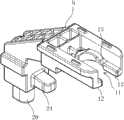
图1是本压力锅开合盖安全装置的立体结构示意图。Fig. 1 is a three-dimensional structure schematic diagram of the safety device for opening and closing the lid of the pressure cooker.
图2是本压力锅开合盖安全装置中下手柄与锅体的结构示意图。Fig. 2 is a structural schematic diagram of the lower handle and the pot body in the safety device for opening and closing the lid of the pressure cooker.
图3是本压力锅开合盖安全装置中推板与止开阀杆的结构示意图。Fig. 3 is a schematic structural view of the push plate and the valve stem for opening and closing the lid of the pressure cooker.
图4是本压力锅开合盖安全装置中推板的结构示意图。Fig. 4 is a schematic structural view of the push plate in the safety device for opening and closing the lid of the pressure cooker.
图5是本压力锅开合盖安全装置中推板另一个角度的结构示意图。Fig. 5 is a structural schematic diagram of another angle of the push plate in the safety device for opening and closing the lid of the pressure cooker.
图6是本压力锅开合盖安全装置合盖前的局部结构剖视示意图。Fig. 6 is a schematic cross-sectional view of a partial structure of the safety device for opening and closing the lid of the pressure cooker before the lid is closed.
图7是本压力锅开合盖安全装置合盖过程中的局部结构剖视示意图。Fig. 7 is a schematic cross-sectional view of a partial structure during the lid closing process of the lid opening and closing safety device of the pressure cooker.
图8是本压力锅开合盖安全装置合盖后的局部结构剖视示意图。Fig. 8 is a schematic cross-sectional view of a partial structure of the lid opening and closing safety device of the pressure cooker after the lid is closed.
图9是本压力锅开合盖安全装置在实施例2中的局部结构剖视图。Fig. 9 is a sectional view of the partial structure of the safety device for opening and closing the lid of the pressure cooker in
图中,1、上手柄;2、阀座;3、锅体;3a、翻沿;4、下手柄;5、锅盖;6、通孔;7、止开阀杆;8、排气孔;9、推板;10、弹簧;11、卡口;12、压肩;13、凸环一;14、定位凹槽;15、滑轨;16、凸环二;17、顶块;18、提升块;19、斜面;20、挡脚;21、滑槽;22、滑入口;23、阻挡面;24、卡脚;25、定位柱一;26、定位柱二。In the figure, 1, upper handle; 2, valve seat; 3, pot body; 3a, turning edge; 4, lower handle; 5, pot cover; 6, through hole; 7, stop valve stem; 8, vent hole ;9, push plate; 10, spring; 11, bayonet; 12, pressure shoulder; 13, protruding ring one; 14, positioning groove; 15, slide rail; 16, protruding ring two; 17, top block; 18, Lifting block; 19, inclined plane; 20, retaining foot; 21, chute; 22, sliding entrance; 23, blocking surface; 24, clamping foot;
具体实施方式Detailed ways
以下是本发明的具体实施例并结合附图,对本发明的技术方案作进一步的描述,但本发明并不限于这些实施例。The following are specific embodiments of the present invention and in conjunction with the accompanying drawings, the technical solutions of the present invention are further described, but the present invention is not limited to these embodiments.
实施例1Example 1
如图1、图2和图6所示,本压力锅开合盖安全装置包括上手柄1、阀座2和固定在锅体3上的下手柄4,锅体3的锅口处具有向外翻折的翻沿3a,上手柄1固定在锅盖5上且上手柄1具有与外界相通的通孔6,阀座2固定在锅盖5上且阀座2中穿设有能升降的止开阀杆7,止开阀杆7位于锅盖5内侧的内端处开有与通孔6相通的排气孔8,上手柄1中设有一块能靠近或远离锅盖5边沿滑动的推板9,推板9与上手柄1之间设有一端抵靠在上手柄1、另一端抵靠在推板9上的弹簧10。为了使弹簧10在合盖过程中不会窜动,保证推板9滑动时的稳定性,推板9上具有定位柱一25,上手柄1内具有定位柱二26,弹簧10两端分别套于定位柱一25和定位柱二26上。As shown in Fig. 1, Fig. 2 and Fig. 6, the opening and closing lid safety device of the pressure cooker comprises an upper handle 1, a
如图3和图4所示,推板9的前端具有供止开阀杆7卡入的卡口11,卡口11的下部具有在合盖时能使止开阀杆7的排气孔8始终与锅体3内部联通的压肩12。止开阀杆7具有周向凸起的凸环一13,凸环一13位于阀座2内且在合盖时,压肩12顶压于凸环一13的上表面。卡口11的下部还具有在合盖后能与上升的止开阀杆7配合使推板9定位的定位结构。如图5所示,本实施例中定位结构包括卡口11下部具有的用于供止开阀杆7嵌入的定位凹槽14,根据实际情况,定位结构还可以为卡口11下部具有的当止开阀杆7上升后能与止开阀杆7抵靠的定位台阶。As shown in Figure 3 and Figure 4, the front end of the
推板9和止开阀杆7之间设有当推板9靠近锅盖5边沿时能使止开阀杆7上升的提升结构。本实施例中提升结构包括卡口11上部具有的滑轨15和止开阀杆7外端处具有的凸环二16,凸环二16位于滑轨15上且滑轨15由卡口11端部向内侧逐渐升高。A lifting structure that can make the
如图4、图5所示,推板9下部处具有卡脚24,当锅盖5与锅体3未正确扣合时卡脚24位于锅体3的锅口和锅盖5之间,且当锅盖5与锅体3正确扣合后卡脚24位于翻沿3a的下方。推板9的后端下部还具有挡脚20,如图2所示,下手柄4上具有供挡脚20插入并能引导推板9滑动的滑槽21,滑槽21具有位于下手柄4侧边的滑入口22,滑入口22的末端折向锅体3且此末端具有阻挡面23。As shown in Fig. 4 and Fig. 5, the lower part of the
本压力锅开合盖安全装置的工作原理如下所述:首先将锅盖5与锅体3扣合,当出现锅盖5与锅体3扣合不到位时,卡脚24位于锅体3的锅口和锅盖5之间使得锅盖5始终不能扣合,避免锅体3内压力上升,有效避免了安全隐患。如图7所示,锅盖5与锅体3正确扣合后,转动上手柄1合盖,推板9被锅盖5的翻沿3a顶触使推板9克服弹簧10的弹力向远离锅盖5翻沿3a的方向滑动,之后推板9的挡脚20会从滑入口22进入滑槽21中,此时推板9由滑槽21引导滑动,滑槽21先将推板9向远离锅盖5边沿方向引导,锅体3的翻沿3a不会顶触到推板9,减少了摩擦,使得合盖过程顺畅。止开阀杆7在重力作用下下降,止开阀杆7上的凸环二16顺着滑轨15下降,凸环一13的下表面与阀座2相抵靠从而阻止止开阀杆7的继续下降,止开阀杆7的排气孔8位于阀座2的密封面下部,推板9的压肩12顶压于凸环一13的上表面,这样使得止开阀杆7不会上升,排气孔8始终与锅体3内部联通,这样合盖过程中锅体3内压力都能从排气孔8中排除,使锅体3内压力不会超过安全的压力值,符合合盖安全性的要求,同时保证合盖过程省力、顺利。The working principle of the safety device for opening and closing the lid of the pressure cooker is as follows: first, the
当锅盖5与锅体3的翻沿3a的扣合面积超过百分之八十五时,滑槽21将推板9向靠近锅盖5边沿方向引导,此时推板9受弹簧10的弹力作用向锅盖5的翻沿3a靠近,之后阻挡面23阻挡挡脚20前进,使得推板9停止滑动。推板9向锅盖5的翻沿3a靠近过程中,压肩12逐渐离开凸环一13的上表面,直至完全不会顶压凸环一13,之后凸环二16顺着逐渐升高的滑轨15而上升,即实现了止开阀杆7上升,如图8所示,当锅盖5与锅体3扣合后,推板9上的卡脚24位于翻沿3a的下方,卡脚24能与翻沿3a相卡合,进一步提高了安全性;此时止开阀杆7内端具有的排气孔8位于阀座2的密封面上,这样减小了排气面积,也缩短了止开阀杆7的上升行程,所以当锅体3内部产生很小的压力时,止开阀杆7就会在压力作用下轻易上升直至止开阀杆7内端固连有的密封圈与阀座2的密封面接触使锅盖5密封,止开阀杆7上升的灵敏性高、时间短,能有效避免锅体3内热量、压力的损失,缩短了烹饪时间,降低了能耗,具有节能作用;另外止开阀杆7上升,止开阀杆7的凸环一13的上端部部分嵌入定位凹槽14中,止开阀杆7使得卡口11不能滑动,即实现了推板9的定位,因此推板9在锅体3内部具有较高压力的情况下是不能滑动的,所以无法开盖,只有当锅体3内压力下降至安全的开启压力值范围内,止开阀杆7才会下降,从而能够开启锅盖5,这样保证了开盖的安全性。When the fastening area of the turning edge 3a of the
实施例2Example 2
如图9所示,本实施例同实施例1的结构和原理基本相同,不一样的地方在于本实施例中提升结构包括卡口11上部具有的顶块17和止开阀杆7外端处具有的周向凸起的提升块18,提升块18与顶块17接触的表面为斜面19,斜面19由卡口11内侧向端部方向向下倾斜。当推板9在弹簧10的弹力作用下向锅体3变压靠近时,顶块17顶触提升块18的斜面19,这样提升块18带动止开阀杆7一起上升,直至止开阀杆7的排气孔8位于阀座2的密封面上。As shown in Figure 9, the structure and principle of this embodiment are basically the same as those of Embodiment 1. The difference lies in that the lifting structure in this embodiment includes the top block 17 on the upper part of the
本文中所描述的具体实施例仅仅是对本发明精神作举例说明。本发明所属技术领域的技术人员可以对所描述的具体实施例做各种各样的修改或补充或采用类似的方式替代,但并不会偏离本发明的精神或者超越所附权利要求书所定义的范围。The specific embodiments described herein are merely illustrative of the spirit of the invention. Those skilled in the art to which the present invention belongs can make various modifications or supplements to the described specific embodiments or adopt similar methods to replace them, but they will not deviate from the spirit of the present invention or go beyond the definition of the appended claims range.
尽管本文较多地使用了上手柄1、阀座2、锅体3、翻沿3a、下手柄4、锅盖5、通孔6、止开阀杆7、排气孔8、推板9、弹簧10、卡口11、压肩12、凸环一13、定位凹槽14、滑轨15、凸环二16、顶块17、提升块18、斜面19、挡脚20、滑槽21、滑入口22、阻挡面23、卡脚24、定位柱一25、定位柱二26等术语,但并不排除使用其它术语的可能性。使用这些术语仅仅是为了更方便地描述和解释本发明的本质;把它们解释成任何一种附加的限制都是与本发明精神相违背的。Although the upper handle 1,
Claims (7)
Translated fromChinesePriority Applications (11)
| Application Number | Priority Date | Filing Date | Title |
|---|---|---|---|
| CN2011102733836ACN102319018B (en) | 2011-09-15 | 2011-09-15 | Pressure cooker opening and closing lid safety device |
| BR112014006182-3ABR112014006182B1 (en) | 2011-09-15 | 2012-09-14 | Pressure cooking device comprising an opening safety means |
| PCT/FR2012/052071WO2013038117A1 (en) | 2011-09-15 | 2012-09-14 | Pressure cooking device comprising an opening safety means |
| EP12772795.6AEP2755531B1 (en) | 2011-09-15 | 2012-09-14 | Pressure cooking device comprising an opening safety means |
| ES12759438.0TES2546907T3 (en) | 2011-09-15 | 2012-09-14 | Safety device for pressure cooker lid |
| EP12759438.0AEP2755530B1 (en) | 2011-09-15 | 2012-09-14 | Safety device for the lid of a pressure cooker |
| PCT/EP2012/068160WO2013037976A1 (en) | 2011-09-15 | 2012-09-14 | Safety device for the lid of a pressure cooker |
| BR112014005959-4ABR112014005959B1 (en) | 2011-09-15 | 2012-09-14 | SAFETY DEVICE FOR PRESSURE COOKER LID |
| ES12772795.6TES2606558T3 (en) | 2011-09-15 | 2012-09-14 | Pressure cooking apparatus comprising a means of opening safety |
| CO14055540ACO6970570A2 (en) | 2011-09-15 | 2014-03-14 | Pressure cooking utensil that includes opening safety means |
| CO14070337ACO6980636A2 (en) | 2011-09-15 | 2014-04-02 | Safety device for pressure cooker lid |
Applications Claiming Priority (1)
| Application Number | Priority Date | Filing Date | Title |
|---|---|---|---|
| CN2011102733836ACN102319018B (en) | 2011-09-15 | 2011-09-15 | Pressure cooker opening and closing lid safety device |
Related Child Applications (1)
| Application Number | Title | Priority Date | Filing Date |
|---|---|---|---|
| CN201310264740.1ADivisionCN103315620B (en) | 2011-09-15 | 2011-09-15 | Cover opening and closing cover safety device of pressure cooker |
Publications (2)
| Publication Number | Publication Date |
|---|---|
| CN102319018A CN102319018A (en) | 2012-01-18 |
| CN102319018Btrue CN102319018B (en) | 2013-11-06 |
Family
ID=45446958
Family Applications (1)
| Application Number | Title | Priority Date | Filing Date |
|---|---|---|---|
| CN2011102733836AActiveCN102319018B (en) | 2011-09-15 | 2011-09-15 | Pressure cooker opening and closing lid safety device |
Country Status (6)
| Country | Link |
|---|---|
| EP (2) | EP2755531B1 (en) |
| CN (1) | CN102319018B (en) |
| BR (2) | BR112014005959B1 (en) |
| CO (2) | CO6970570A2 (en) |
| ES (2) | ES2546907T3 (en) |
| WO (2) | WO2013037976A1 (en) |
Cited By (11)
| Publication number | Priority date | Publication date | Assignee | Title |
|---|---|---|---|---|
| US10390656B2 (en) | 2017-08-09 | 2019-08-27 | Sharkninja Operating Llc | Cooking device and components thereof |
| USD873602S1 (en) | 2018-08-09 | 2020-01-28 | Sharkninja Operating Llc | Lid part of a food preparation device |
| USD874211S1 (en) | 2018-08-09 | 2020-02-04 | Sharkninja Operating Llc | Food preparation device and parts thereof |
| USD903413S1 (en) | 2018-08-09 | 2020-12-01 | Sharkninja Operating Llc | Cooking basket |
| USD914436S1 (en) | 2018-06-19 | 2021-03-30 | Sharkninja Operating Llc | Air diffuser with food preparation pot |
| USD918654S1 (en) | 2019-06-06 | 2021-05-11 | Sharkninja Operating Llc | Grill plate |
| US11033146B2 (en) | 2019-02-25 | 2021-06-15 | Sharkninja Operating Llc | Cooking device and components thereof |
| USD922126S1 (en) | 2019-06-06 | 2021-06-15 | Sharkninja Operating Llc | User interface for a food preparation device |
| US11134808B2 (en) | 2020-03-30 | 2021-10-05 | Sharkninja Operating Llc | Cooking device and components thereof |
| USD932833S1 (en) | 2018-08-09 | 2021-10-12 | Sharkninja Operating Llc | Reversible cooking rack |
| US11751710B2 (en) | 2019-02-25 | 2023-09-12 | Sharkninja Operating Llc | Guard for cooking system |
Families Citing this family (4)
| Publication number | Priority date | Publication date | Assignee | Title |
|---|---|---|---|---|
| FR3046043B1 (en)* | 2015-12-23 | 2018-01-26 | Seb S.A. | REINFORCING COOKER |
| CN106439641B (en)* | 2016-08-31 | 2019-02-22 | 宁波奇驰照明灯具有限公司 | LED ceiling lamp |
| CN111568168B (en)* | 2020-05-29 | 2021-07-02 | 中山市元亨家居用品有限公司 | An adjustable pressure cooker lid |
| CN114847771B (en)* | 2022-06-16 | 2023-09-12 | 德奥通用航空股份有限公司 | Pot cover locking mechanism and micro-pressure air fryer |
Citations (3)
| Publication number | Priority date | Publication date | Assignee | Title |
|---|---|---|---|---|
| CN2275415Y (en)* | 1997-01-24 | 1998-03-04 | 南海市幸福压力锅厂 | Double card safety valve for safety opening pressure cooker cover |
| CN101731940A (en)* | 2010-02-05 | 2010-06-16 | 浙江苏泊尔股份有限公司 | Safety opening-closing cover device of pressure cooker |
| CN202262832U (en)* | 2011-09-15 | 2012-06-06 | 浙江苏泊尔股份有限公司 | Safety device for opening and closing cover of pressure cooker |
Family Cites Families (7)
| Publication number | Priority date | Publication date | Assignee | Title |
|---|---|---|---|---|
| DE2901639A1 (en)* | 1979-01-17 | 1980-07-24 | Braun & Kemmler | STEAM PRESSURE COOKER |
| GR81031B (en)* | 1983-11-30 | 1985-03-22 | Radar S Coop | Regulation and control device for pressure cookers |
| JPS6094121U (en)* | 1983-12-06 | 1985-06-27 | 理研軽金属工業株式会社 | Pressure cooker pressure regulator |
| FR2560027B1 (en)* | 1984-02-29 | 1986-11-14 | Seb Sa | SECURITY DEVICE FOR CLOSING AND OPENING A PRESSURE COOKING APPARATUS |
| YU44952B (en)* | 1987-07-13 | 1991-04-30 | Emo Celje | Device for preventing opening of pressure cooker under pressure |
| ES2223758T3 (en)* | 2001-09-25 | 2005-03-01 | Compañia De Menaje Domestico Sl | SAFETY DEVICE FOR PRESSURE POTS. |
| EP1582122A1 (en)* | 2004-03-31 | 2005-10-05 | Compania de Menaje Domestico SL | Safety device for pressure cookers |
- 2011
- 2011-09-15CNCN2011102733836Apatent/CN102319018B/enactiveActive
- 2012
- 2012-09-14WOPCT/EP2012/068160patent/WO2013037976A1/enactiveApplication Filing
- 2012-09-14BRBR112014005959-4Apatent/BR112014005959B1/enactiveIP Right Grant
- 2012-09-14BRBR112014006182-3Apatent/BR112014006182B1/enactiveIP Right Grant
- 2012-09-14ESES12759438.0Tpatent/ES2546907T3/enactiveActive
- 2012-09-14WOPCT/FR2012/052071patent/WO2013038117A1/enactiveApplication Filing
- 2012-09-14EPEP12772795.6Apatent/EP2755531B1/enactiveActive
- 2012-09-14ESES12772795.6Tpatent/ES2606558T3/enactiveActive
- 2012-09-14EPEP12759438.0Apatent/EP2755530B1/enactiveActive
- 2014
- 2014-03-14COCO14055540Apatent/CO6970570A2/enunknown
- 2014-04-02COCO14070337Apatent/CO6980636A2/enunknown
Patent Citations (3)
| Publication number | Priority date | Publication date | Assignee | Title |
|---|---|---|---|---|
| CN2275415Y (en)* | 1997-01-24 | 1998-03-04 | 南海市幸福压力锅厂 | Double card safety valve for safety opening pressure cooker cover |
| CN101731940A (en)* | 2010-02-05 | 2010-06-16 | 浙江苏泊尔股份有限公司 | Safety opening-closing cover device of pressure cooker |
| CN202262832U (en)* | 2011-09-15 | 2012-06-06 | 浙江苏泊尔股份有限公司 | Safety device for opening and closing cover of pressure cooker |
Cited By (70)
| Publication number | Priority date | Publication date | Assignee | Title |
|---|---|---|---|---|
| US11445856B2 (en) | 2017-08-09 | 2022-09-20 | Sharkninja Operating Llc | Cooking device and components thereof |
| US10390656B2 (en) | 2017-08-09 | 2019-08-27 | Sharkninja Operating Llc | Cooking device and components thereof |
| US10405698B2 (en) | 2017-08-09 | 2019-09-10 | Sharkninja Operating Llc | Cooking device and components thereof |
| US10413122B2 (en) | 2017-08-09 | 2019-09-17 | Sharkninja Operating Llc | Cooking device and components thereof |
| US10413121B2 (en) | 2017-08-09 | 2019-09-17 | Sharkninja Operating Llc | Cooking device and components thereof |
| US10485378B2 (en) | 2017-08-09 | 2019-11-26 | Sharkninja Operating Llc | Cooking device and components thereof |
| US11889950B2 (en) | 2017-08-09 | 2024-02-06 | Sharkninja Operating Llc | Cooking device and components thereof |
| US11759049B2 (en) | 2017-08-09 | 2023-09-19 | Sharkninja Operating Llc | Cooking device and components thereof |
| US11759048B2 (en) | 2017-08-09 | 2023-09-19 | Sharkninja Operating Llc | Cooking device and components thereof |
| US11627834B2 (en) | 2017-08-09 | 2023-04-18 | Sharkninja Operating Llc | Cooking system for cooking food |
| US11547242B2 (en) | 2017-08-09 | 2023-01-10 | Sharkninja Operating Llc | Cooking device and components thereof |
| US11547243B2 (en) | 2017-08-09 | 2023-01-10 | Sharkninja Operating Llc | Cooking device and components thereof |
| US10405697B2 (en) | 2017-08-09 | 2019-09-10 | Sharkninja Operating Llc | Cooking device and components thereof |
| US11399657B2 (en) | 2017-08-09 | 2022-08-02 | Sharkninja Operating Llc | Cooking device and components thereof |
| US10646070B2 (en) | 2017-08-09 | 2020-05-12 | Sharkninja Operating Llc | Cooking device and components thereof |
| US10653270B2 (en) | 2017-08-09 | 2020-05-19 | Sharkninja Operating Llc | Cooking device and components thereof |
| US10660472B2 (en) | 2017-08-09 | 2020-05-26 | Sharkninja Operating Llc | Cooking device and components thereof |
| US10674868B2 (en) | 2017-08-09 | 2020-06-09 | Sharkninja Operating Llc | Cooking device and components thereof |
| US10682011B2 (en) | 2017-08-09 | 2020-06-16 | Sharkninja Operating Llc | Cooking device and components thereof |
| US11363910B2 (en) | 2017-08-09 | 2022-06-21 | Sharkninja Operating Llc | Cooking device and components thereof |
| US11304561B2 (en) | 2017-08-09 | 2022-04-19 | Sharkninja Operating Llc | Cooking device and components thereof |
| US11278151B2 (en) | 2017-08-09 | 2022-03-22 | Sharkninja Operating Llc | Cooking device and components thereof |
| US11266267B2 (en) | 2017-08-09 | 2022-03-08 | Sharkninja Operating Llc | Cooking device and components thereof |
| US11266268B2 (en) | 2017-08-09 | 2022-03-08 | Sharkninja Operating Llc | Cooking device and components thereof |
| US11109710B2 (en) | 2017-08-09 | 2021-09-07 | Sharkninja Operating Llc | Cooking device and components thereof |
| US11089903B2 (en) | 2017-08-09 | 2021-08-17 | Sharkninja Operating Llc | Cooking device and components thereof |
| US11089902B2 (en) | 2017-08-09 | 2021-08-17 | Sharkninja Operating Llc | Cooking device and components thereof |
| USD914447S1 (en) | 2018-06-19 | 2021-03-30 | Sharkninja Operating Llc | Air diffuser |
| USD948938S1 (en) | 2018-06-19 | 2022-04-19 | Sharkninja Operating Llc | Air diffuser |
| USD914436S1 (en) | 2018-06-19 | 2021-03-30 | Sharkninja Operating Llc | Air diffuser with food preparation pot |
| USD941090S1 (en) | 2018-08-09 | 2022-01-18 | Sharkninja Operating Llc | Cooking basket |
| USD935259S1 (en) | 2018-08-09 | 2021-11-09 | Sharkninja Operating Llc | Food preparation device |
| USD929793S1 (en) | 2018-08-09 | 2021-09-07 | Sharkninja Operating Llc | Food preparation device |
| USD874211S1 (en) | 2018-08-09 | 2020-02-04 | Sharkninja Operating Llc | Food preparation device and parts thereof |
| USD873602S1 (en) | 2018-08-09 | 2020-01-28 | Sharkninja Operating Llc | Lid part of a food preparation device |
| USD929794S1 (en) | 2018-08-09 | 2021-09-07 | Sharkninja Operating Llc | Food preparation device |
| USD876874S1 (en) | 2018-08-09 | 2020-03-03 | Sharkninja Operating Llc | User interface for a food preparation device |
| USD932833S1 (en) | 2018-08-09 | 2021-10-12 | Sharkninja Operating Llc | Reversible cooking rack |
| USD883014S1 (en) | 2018-08-09 | 2020-05-05 | Sharkninja Operating Llc | Food preparation device |
| USD934027S1 (en) | 2018-08-09 | 2021-10-26 | Sharkninja Operating Llc | Reversible cooking rack |
| USD931680S1 (en) | 2018-08-09 | 2021-09-28 | Sharkninja Operating Llc | Cooking basket |
| USD883016S1 (en) | 2018-08-09 | 2020-05-05 | Sharkninja Operating Llc | Food preparation device and parts thereof |
| USD940503S1 (en) | 2018-08-09 | 2022-01-11 | Sharkninja Operating Llc | Cooking basket |
| USD876160S1 (en) | 2018-08-09 | 2020-02-25 | Sharkninja Operating Llc | Food preparation device and parts thereof |
| USD929173S1 (en) | 2018-08-09 | 2021-08-31 | Sharkninja Operating Llc | Food preparation device |
| USD920732S1 (en) | 2018-08-09 | 2021-06-01 | Sharkninja Operating Llc | Food preparation device |
| USD883017S1 (en) | 2018-08-09 | 2020-05-05 | Sharkninja Operating Llc | User interface for food preparation device |
| USD903414S1 (en) | 2018-08-09 | 2020-12-01 | Sharkninja Operating Llc | Cooking basket |
| USD903415S1 (en) | 2018-08-09 | 2020-12-01 | Sharkninja Operating Llc | Cooking basket |
| USD903413S1 (en) | 2018-08-09 | 2020-12-01 | Sharkninja Operating Llc | Cooking basket |
| USD883015S1 (en) | 2018-08-09 | 2020-05-05 | Sharkninja Operating Llc | Food preparation device and parts thereof |
| US11363911B2 (en) | 2019-02-25 | 2022-06-21 | Sharkninja Operating Llc | Cooking device and components thereof |
| US11051654B2 (en) | 2019-02-25 | 2021-07-06 | Sharkninja Operating Llc | Cooking device and components thereof |
| US11033146B2 (en) | 2019-02-25 | 2021-06-15 | Sharkninja Operating Llc | Cooking device and components thereof |
| US11147415B2 (en) | 2019-02-25 | 2021-10-19 | Sharkninja Operating Llc | Cooking device and components thereof |
| US11832761B2 (en) | 2019-02-25 | 2023-12-05 | Sharkninja Operating Llc | Cooking device and components thereof |
| US11766152B2 (en) | 2019-02-25 | 2023-09-26 | Sharkninja Operating Llc | Cooking device and components thereof |
| US12226039B2 (en) | 2019-02-25 | 2025-02-18 | Sharkninja Operating Llc | Guard for cooking system |
| US11751710B2 (en) | 2019-02-25 | 2023-09-12 | Sharkninja Operating Llc | Guard for cooking system |
| US11751722B2 (en) | 2019-02-25 | 2023-09-12 | Sharkninja Operating Llc | Cooking device and components thereof |
| USD922126S1 (en) | 2019-06-06 | 2021-06-15 | Sharkninja Operating Llc | User interface for a food preparation device |
| USD934631S1 (en) | 2019-06-06 | 2021-11-02 | Sharkninja Operating Llc | Grill plate |
| USD1015798S1 (en) | 2019-06-06 | 2024-02-27 | Sharkninja Operating Llc | Food preparation device |
| USD1049746S1 (en) | 2019-06-06 | 2024-11-05 | Sharkninja Operating Llc | Food preparation device |
| USD1054771S1 (en) | 2019-06-06 | 2024-12-24 | Sharkninja Operating Llc | Food preparation device |
| USD918654S1 (en) | 2019-06-06 | 2021-05-11 | Sharkninja Operating Llc | Grill plate |
| US11678765B2 (en) | 2020-03-30 | 2023-06-20 | Sharkninja Operating Llc | Cooking device and components thereof |
| US11647861B2 (en) | 2020-03-30 | 2023-05-16 | Sharkninja Operating Llc | Cooking device and components thereof |
| US11134808B2 (en) | 2020-03-30 | 2021-10-05 | Sharkninja Operating Llc | Cooking device and components thereof |
| US11969118B2 (en) | 2020-03-30 | 2024-04-30 | Sharkninja Operating Llc | Cooking device and components thereof |
Also Published As
| Publication number | Publication date |
|---|---|
| CO6980636A2 (en) | 2014-06-27 |
| CN102319018A (en) | 2012-01-18 |
| EP2755531A1 (en) | 2014-07-23 |
| BR112014005959A2 (en) | 2017-04-04 |
| EP2755531B1 (en) | 2016-10-12 |
| EP2755530A1 (en) | 2014-07-23 |
| EP2755530B1 (en) | 2015-08-12 |
| WO2013037976A1 (en) | 2013-03-21 |
| ES2546907T3 (en) | 2015-09-29 |
| CO6970570A2 (en) | 2014-06-13 |
| BR112014006182B1 (en) | 2022-03-15 |
| WO2013038117A1 (en) | 2013-03-21 |
| BR112014005959B1 (en) | 2020-06-16 |
| ES2606558T3 (en) | 2017-03-24 |
| BR112014006182A2 (en) | 2017-06-13 |
Similar Documents
| Publication | Publication Date | Title |
|---|---|---|
| CN102319018B (en) | Pressure cooker opening and closing lid safety device | |
| CN204500194U (en) | There is the cup of anti-down function | |
| CN102846183B (en) | Electric rice cooker | |
| CN107874602B (en) | Pressure cooker | |
| KR101120358B1 (en) | Safety water cock valve for hot water | |
| KR101379001B1 (en) | Cooker cover for cooking receptacle | |
| CN201585842U (en) | Electric pressure cooker | |
| CN106983331A (en) | A kind of cup lid | |
| CN103315620B (en) | Cover opening and closing cover safety device of pressure cooker | |
| CN204765132U (en) | Electric rice cooker | |
| CN201373149Y (en) | Main steam safety valve | |
| CN202262832U (en) | Safety device for opening and closing cover of pressure cooker | |
| CN106641383B (en) | Electromagnetic valve | |
| CN103919481B (en) | A kind of safety heat-preserving kettle | |
| CN202553521U (en) | Pressure relief structure of pressure cooking utensil | |
| CN211484184U (en) | Kettle lid with pressing and exhausting functions | |
| CN202820886U (en) | Electric cooker | |
| KR20150002508U (en) | Stopper for vacuum bottle | |
| CN209629316U (en) | A kind of novel exhaust cup lid | |
| CN204473467U (en) | A kind of safe and reliable emulsion pumps | |
| CN218044650U (en) | Push type unthreaded drinking cup | |
| CN202743658U (en) | Medicine bottle capable of being prevented from being opened by child | |
| CN104382485A (en) | Opening and closing mechanism of pressure cooker | |
| CN206761428U (en) | Electric pressure cooker | |
| CN202820916U (en) | Pressure cooker |
Legal Events
| Date | Code | Title | Description |
|---|---|---|---|
| C06 | Publication | ||
| PB01 | Publication | ||
| C10 | Entry into substantive examination | ||
| SE01 | Entry into force of request for substantive examination | ||
| C14 | Grant of patent or utility model | ||
| GR01 | Patent grant |