CN102317051A - Be used to form the method and system of multi-layer product - Google Patents
Be used to form the method and system of multi-layer productDownload PDFInfo
- Publication number
- CN102317051A CN102317051ACN2008800205220ACN200880020522ACN102317051ACN 102317051 ACN102317051 ACN 102317051ACN 2008800205220 ACN2008800205220 ACN 2008800205220ACN 200880020522 ACN200880020522 ACN 200880020522ACN 102317051 ACN102317051 ACN 102317051A
- Authority
- CN
- China
- Prior art keywords
- core
- core rod
- preform
- mold
- fluid
- Prior art date
- Legal status (The legal status is an assumption and is not a legal conclusion. Google has not performed a legal analysis and makes no representation as to the accuracy of the status listed.)
- Pending
Links
- 238000000034methodMethods0.000titleclaimsdescription129
- 239000012530fluidSubstances0.000claimsabstractdescription384
- 239000012809cooling fluidSubstances0.000claimsabstractdescription59
- 239000000463materialSubstances0.000claimsdescription280
- 238000000465mouldingMethods0.000claimsdescription219
- 238000001816coolingMethods0.000claimsdescription163
- 238000012546transferMethods0.000claimsdescription132
- 238000002347injectionMethods0.000claimsdescription68
- 239000007924injectionSubstances0.000claimsdescription68
- 238000011282treatmentMethods0.000claimsdescription36
- 230000000694effectsEffects0.000claimsdescription33
- 238000001746injection mouldingMethods0.000claimsdescription32
- 229920003023plasticPolymers0.000claimsdescription25
- 239000004033plasticSubstances0.000claimsdescription25
- 238000004381surface treatmentMethods0.000claimsdescription25
- 238000012545processingMethods0.000claimsdescription22
- 229920001169thermoplasticPolymers0.000claimsdescription22
- 239000004416thermosoftening plasticSubstances0.000claimsdescription22
- 238000002360preparation methodMethods0.000claimsdescription14
- 238000003851corona treatmentMethods0.000claimsdescription9
- 238000005299abrasionMethods0.000claimsdescription8
- 230000015572biosynthetic processEffects0.000claimsdescription5
- 230000036961partial effectEffects0.000claimsdescription4
- 230000017105transpositionEffects0.000claimsdescription3
- 239000002650laminated plasticSubstances0.000claims3
- 238000012797qualificationMethods0.000claims2
- 238000005516engineering processMethods0.000claims1
- 239000010410layerSubstances0.000description199
- 239000005020polyethylene terephthalateSubstances0.000description125
- 229920000139polyethylene terephthalatePolymers0.000description125
- 210000003739neckAnatomy0.000description94
- 238000000576coating methodMethods0.000description62
- 230000008569processEffects0.000description52
- 239000011248coating agentSubstances0.000description49
- 239000003507refrigerantSubstances0.000description48
- 230000004888barrier functionEffects0.000description27
- 239000003570airSubstances0.000description26
- 239000007788liquidSubstances0.000description26
- CURLTUGMZLYLDI-UHFFFAOYSA-NCarbon dioxideChemical compoundO=C=OCURLTUGMZLYLDI-UHFFFAOYSA-N0.000description22
- 238000002425crystallisationMethods0.000description22
- 230000008025crystallizationEffects0.000description22
- -1polyethylene terephthalatePolymers0.000description22
- 230000002829reductive effectEffects0.000description21
- 239000012815thermoplastic materialSubstances0.000description21
- 238000000071blow mouldingMethods0.000description20
- 239000007789gasSubstances0.000description20
- 238000004519manufacturing processMethods0.000description20
- 239000000155meltSubstances0.000description20
- 238000004891communicationMethods0.000description19
- 239000000498cooling waterSubstances0.000description19
- XLYOFNOQVPJJNP-UHFFFAOYSA-NwaterSubstancesOXLYOFNOQVPJJNP-UHFFFAOYSA-N0.000description19
- 229920000642polymerPolymers0.000description18
- 238000010438heat treatmentMethods0.000description17
- 239000000758substrateSubstances0.000description16
- RYGMFSIKBFXOCR-UHFFFAOYSA-NCopperChemical compound[Cu]RYGMFSIKBFXOCR-UHFFFAOYSA-N0.000description13
- 229920005989resinPolymers0.000description13
- 239000011347resinSubstances0.000description13
- 239000002356single layerSubstances0.000description13
- 239000010949copperSubstances0.000description12
- 229920000728polyesterPolymers0.000description12
- 229910002092carbon dioxideInorganic materials0.000description11
- 230000001276controlling effectEffects0.000description11
- 229910052802copperInorganic materials0.000description11
- 239000000203mixtureSubstances0.000description11
- 239000012768molten materialSubstances0.000description11
- 229910045601alloyInorganic materials0.000description10
- 239000000956alloySubstances0.000description10
- 239000011800void materialSubstances0.000description10
- IJGRMHOSHXDMSA-UHFFFAOYSA-NAtomic nitrogenChemical compoundN#NIJGRMHOSHXDMSA-UHFFFAOYSA-N0.000description9
- 229920001577copolymerPolymers0.000description9
- 238000009826distributionMethods0.000description9
- 230000001965increasing effectEffects0.000description9
- 230000000670limiting effectEffects0.000description9
- 229920000098polyolefinPolymers0.000description9
- 239000004743PolypropyleneSubstances0.000description8
- 238000009835boilingMethods0.000description8
- 238000009833condensationMethods0.000description8
- 230000005494condensationEffects0.000description8
- 229910000831SteelInorganic materials0.000description7
- 230000008901benefitEffects0.000description7
- 239000001569carbon dioxideSubstances0.000description7
- 239000010959steelSubstances0.000description7
- XEEYBQQBJWHFJM-UHFFFAOYSA-NIronChemical compound[Fe]XEEYBQQBJWHFJM-UHFFFAOYSA-N0.000description6
- ATBAMAFKBVZNFJ-UHFFFAOYSA-Nberyllium atomChemical compound[Be]ATBAMAFKBVZNFJ-UHFFFAOYSA-N0.000description6
- 235000013305foodNutrition0.000description6
- 230000001105regulatory effectEffects0.000description6
- 229910000881Cu alloyInorganic materials0.000description5
- 239000004698PolyethyleneSubstances0.000description5
- 229910001315Tool steelInorganic materials0.000description5
- 239000000654additiveSubstances0.000description5
- 229910052790berylliumInorganic materials0.000description5
- 235000013361beverageNutrition0.000description5
- 230000008859changeEffects0.000description5
- 239000002178crystalline materialSubstances0.000description5
- 238000013461designMethods0.000description5
- 239000006260foamSubstances0.000description5
- 239000004793PolystyreneSubstances0.000description4
- NIXOWILDQLNWCW-UHFFFAOYSA-Nacrylic acid groupChemical groupC(C=C)(=O)ONIXOWILDQLNWCW-UHFFFAOYSA-N0.000description4
- QVGXLLKOCUKJST-UHFFFAOYSA-Natomic oxygenChemical compound[O]QVGXLLKOCUKJST-UHFFFAOYSA-N0.000description4
- 230000003750conditioning effectEffects0.000description4
- 229920006226ethylene-acrylic acidPolymers0.000description4
- 238000002955isolationMethods0.000description4
- 230000013011matingEffects0.000description4
- 238000002844meltingMethods0.000description4
- 229910052757nitrogenInorganic materials0.000description4
- 239000001301oxygenSubstances0.000description4
- 229910052760oxygenInorganic materials0.000description4
- 238000004806packaging method and processMethods0.000description4
- 229920005644polyethylene terephthalate glycol copolymerPolymers0.000description4
- 229920001155polypropylenePolymers0.000description4
- 230000009467reductionEffects0.000description4
- 229920002873PolyethyleniminePolymers0.000description3
- 239000012298atmosphereSubstances0.000description3
- 235000014171carbonated beverageNutrition0.000description3
- 238000000748compression mouldingMethods0.000description3
- 238000006073displacement reactionMethods0.000description3
- 229920001971elastomerPolymers0.000description3
- 239000000806elastomerSubstances0.000description3
- 239000003623enhancerSubstances0.000description3
- 239000005038ethylene vinyl acetateSubstances0.000description3
- 238000013007heat curingMethods0.000description3
- 229910052742ironInorganic materials0.000description3
- 230000008018meltingEffects0.000description3
- 230000002093peripheral effectEffects0.000description3
- 125000000951phenoxy groupChemical group[H]C1=C([H])C([H])=C(O*)C([H])=C1[H]0.000description3
- 229920003207poly(ethylene-2,6-naphthalate)Polymers0.000description3
- 229920001200poly(ethylene-vinyl acetate)Polymers0.000description3
- 229920002223polystyrenePolymers0.000description3
- 230000003068static effectEffects0.000description3
- 239000000126substanceSubstances0.000description3
- 230000005514two-phase flowEffects0.000description3
- 230000008016vaporizationEffects0.000description3
- 229910000952Be alloyInorganic materials0.000description2
- 239000004604Blowing AgentSubstances0.000description2
- 229920001634CopolyesterPolymers0.000description2
- 239000004971Cross linkerSubstances0.000description2
- LYCAIKOWRPUZTN-UHFFFAOYSA-NEthylene glycolChemical compoundOCCOLYCAIKOWRPUZTN-UHFFFAOYSA-N0.000description2
- 229920000034PlastomerPolymers0.000description2
- 239000004952PolyamideSubstances0.000description2
- 229920000954PolyglycolidePolymers0.000description2
- PPBRXRYQALVLMV-UHFFFAOYSA-NStyreneChemical compoundC=CC1=CC=CC=C1PPBRXRYQALVLMV-UHFFFAOYSA-N0.000description2
- 230000006750UV protectionEffects0.000description2
- 125000000217alkyl groupChemical group0.000description2
- 239000012080ambient airSubstances0.000description2
- 230000001143conditioned effectEffects0.000description2
- 239000002826coolantSubstances0.000description2
- 239000013078crystalSubstances0.000description2
- 125000004122cyclic groupChemical group0.000description2
- 230000001419dependent effectEffects0.000description2
- 238000010586diagramMethods0.000description2
- 239000003814drugSubstances0.000description2
- 229940079593drugDrugs0.000description2
- 125000003700epoxy groupChemical group0.000description2
- 238000011067equilibrationMethods0.000description2
- 238000001125extrusionMethods0.000description2
- 238000010101extrusion blow mouldingMethods0.000description2
- 238000011049fillingMethods0.000description2
- 239000000796flavoring agentSubstances0.000description2
- 235000019634flavorsNutrition0.000description2
- 239000011521glassSubstances0.000description2
- 239000001307heliumSubstances0.000description2
- 229910052734heliumInorganic materials0.000description2
- SWQJXJOGLNCZEY-UHFFFAOYSA-Nhelium atomChemical compound[He]SWQJXJOGLNCZEY-UHFFFAOYSA-N0.000description2
- 239000011810insulating materialSubstances0.000description2
- 238000009413insulationMethods0.000description2
- 230000003993interactionEffects0.000description2
- 229920000092linear low density polyethylenePolymers0.000description2
- 239000004707linear low-density polyethyleneSubstances0.000description2
- PGYPOBZJRVSMDS-UHFFFAOYSA-Nloperamide hydrochlorideChemical compoundCl.C=1C=CC=CC=1C(C=1C=CC=CC=1)(C(=O)N(C)C)CCN(CC1)CCC1(O)C1=CC=C(Cl)C=C1PGYPOBZJRVSMDS-UHFFFAOYSA-N0.000description2
- 229910052751metalInorganic materials0.000description2
- 239000002184metalSubstances0.000description2
- 230000000704physical effectEffects0.000description2
- 229920003229poly(methyl methacrylate)Polymers0.000description2
- 229920002647polyamidePolymers0.000description2
- 229920000515polycarbonatePolymers0.000description2
- 239000004417polycarbonateSubstances0.000description2
- 229920000570polyetherPolymers0.000description2
- 229920000573polyethylenePolymers0.000description2
- 239000004633polyglycolic acidSubstances0.000description2
- 239000004626polylactic acidSubstances0.000description2
- 229920006124polyolefin elastomerPolymers0.000description2
- 229920002451polyvinyl alcoholPolymers0.000description2
- 230000002000scavenging effectEffects0.000description2
- 238000000926separation methodMethods0.000description2
- 239000007787solidSubstances0.000description2
- 230000008646thermal stressEffects0.000description2
- 238000011144upstream manufacturingMethods0.000description2
- 238000009834vaporizationMethods0.000description2
- DJCYQEDZXFZHRL-UHFFFAOYSA-N2-(2-hydroxyphenoxy)peroxyphenolChemical compoundOC1=CC=CC=C1OOOC1=CC=CC=C1ODJCYQEDZXFZHRL-UHFFFAOYSA-N0.000description1
- UUODQIKUTGWMPT-UHFFFAOYSA-N2-fluoro-5-(trifluoromethyl)pyridineChemical compoundFC1=CC=C(C(F)(F)F)C=N1UUODQIKUTGWMPT-UHFFFAOYSA-N0.000description1
- SENMPMXZMGNQAG-UHFFFAOYSA-N3,4-dihydro-2,5-benzodioxocine-1,6-dioneChemical compoundO=C1OCCOC(=O)C2=CC=CC=C12SENMPMXZMGNQAG-UHFFFAOYSA-N0.000description1
- KKOWMCYVIXBCGE-UHFFFAOYSA-N3-(2-hydroxyethoxy)phenolChemical compoundOCCOC1=CC=CC(O)=C1KKOWMCYVIXBCGE-UHFFFAOYSA-N0.000description1
- LLLVZDVNHNWSDS-UHFFFAOYSA-N4-methylidene-3,5-dioxabicyclo[5.2.2]undeca-1(9),7,10-triene-2,6-dioneChemical compoundC1(C2=CC=C(C(=O)OC(=C)O1)C=C2)=OLLLVZDVNHNWSDS-UHFFFAOYSA-N0.000description1
- NLHHRLWOUZZQLW-UHFFFAOYSA-NAcrylonitrileChemical compoundC=CC#NNLHHRLWOUZZQLW-UHFFFAOYSA-N0.000description1
- 229910000967As alloyInorganic materials0.000description1
- GXGJIOMUZAGVEH-UHFFFAOYSA-NChamazuleneChemical groupCCC1=CC=C(C)C2=CC=C(C)C2=C1GXGJIOMUZAGVEH-UHFFFAOYSA-N0.000description1
- VOPWNXZWBYDODV-UHFFFAOYSA-NChlorodifluoromethaneChemical compoundFC(F)ClVOPWNXZWBYDODV-UHFFFAOYSA-N0.000description1
- VYZAMTAEIAYCRO-UHFFFAOYSA-NChromiumChemical compound[Cr]VYZAMTAEIAYCRO-UHFFFAOYSA-N0.000description1
- 235000010919Copernicia pruniferaNutrition0.000description1
- 244000180278Copernicia pruniferaSpecies0.000description1
- 229920000089Cyclic olefin copolymerPolymers0.000description1
- 239000004593EpoxySubstances0.000description1
- JOYRKODLDBILNP-UHFFFAOYSA-NEthyl urethaneChemical compoundCCOC(N)=OJOYRKODLDBILNP-UHFFFAOYSA-N0.000description1
- 229920000181Ethylene propylene rubberPolymers0.000description1
- 229920000219Ethylene vinyl alcoholPolymers0.000description1
- BDAGIHXWWSANSR-UHFFFAOYSA-MFormateChemical compound[O-]C=OBDAGIHXWWSANSR-UHFFFAOYSA-M0.000description1
- UFHFLCQGNIYNRP-UHFFFAOYSA-NHydrogenChemical compound[H][H]UFHFLCQGNIYNRP-UHFFFAOYSA-N0.000description1
- 229920010126Linear Low Density Polyethylene (LLDPE)Polymers0.000description1
- 229920002292Nylon 6Polymers0.000description1
- 229920002302Nylon 6,6Polymers0.000description1
- 229940123973Oxygen scavengerDrugs0.000description1
- JFZHPFOXAAIUMB-UHFFFAOYSA-NPhenylethylmalonamideChemical compoundCCC(C(N)=O)(C(N)=O)C1=CC=CC=C1JFZHPFOXAAIUMB-UHFFFAOYSA-N0.000description1
- 229930182556PolyacetalNatural products0.000description1
- 239000004372Polyvinyl alcoholSubstances0.000description1
- BQCADISMDOOEFD-UHFFFAOYSA-NSilverChemical compound[Ag]BQCADISMDOOEFD-UHFFFAOYSA-N0.000description1
- ATJFFYVFTNAWJD-UHFFFAOYSA-NTinChemical compound[Sn]ATJFFYVFTNAWJD-UHFFFAOYSA-N0.000description1
- QCWXUUIWCKQGHC-UHFFFAOYSA-NZirconiumChemical compound[Zr]QCWXUUIWCKQGHC-UHFFFAOYSA-N0.000description1
- 239000006096absorbing agentSubstances0.000description1
- 229920006243acrylic copolymerPolymers0.000description1
- 229920006397acrylic thermoplasticPolymers0.000description1
- XECAHXYUAAWDEL-UHFFFAOYSA-Nacrylonitrile butadiene styreneChemical compoundC=CC=C.C=CC#N.C=CC1=CC=CC=C1XECAHXYUAAWDEL-UHFFFAOYSA-N0.000description1
- 229920000122acrylonitrile butadiene styrenePolymers0.000description1
- 239000004676acrylonitrile butadiene styreneSubstances0.000description1
- 230000006978adaptationEffects0.000description1
- 230000000996additive effectEffects0.000description1
- 239000000853adhesiveSubstances0.000description1
- 230000001070adhesive effectEffects0.000description1
- 230000002411adverseEffects0.000description1
- 150000001299aldehydesChemical class0.000description1
- 150000001412aminesChemical class0.000description1
- 229920006125amorphous polymerPolymers0.000description1
- 230000003254anti-foaming effectEffects0.000description1
- 239000007866anti-wear additiveSubstances0.000description1
- 239000002518antifoaming agentSubstances0.000description1
- 238000013459approachMethods0.000description1
- 229920003235aromatic polyamidePolymers0.000description1
- 230000009286beneficial effectEffects0.000description1
- HUFIRBOBXZUFPV-UHFFFAOYSA-Nbenzene-1,3-diolChemical classOC1=CC=CC(O)=C1.OC1=CC=CC(O)=C1HUFIRBOBXZUFPV-UHFFFAOYSA-N0.000description1
- 239000011230binding agentSubstances0.000description1
- 230000033228biological regulationEffects0.000description1
- 230000005540biological transmissionEffects0.000description1
- 238000007664blowingMethods0.000description1
- DQXBYHZEEUGOBF-UHFFFAOYSA-Nbut-3-enoic acid;etheneChemical compoundC=C.OC(=O)CC=CDQXBYHZEEUGOBF-UHFFFAOYSA-N0.000description1
- 239000006229carbon blackSubstances0.000description1
- 229910052804chromiumInorganic materials0.000description1
- 239000011651chromiumSubstances0.000description1
- 239000003086colorantSubstances0.000description1
- 230000006835compressionEffects0.000description1
- 238000007906compressionMethods0.000description1
- 238000010276constructionMethods0.000description1
- 239000000110cooling liquidSubstances0.000description1
- 239000007799corkSubstances0.000description1
- 239000002537cosmeticSubstances0.000description1
- 239000004078cryogenic materialSubstances0.000description1
- 150000001925cycloalkenesChemical class0.000description1
- 125000004956cyclohexylene groupChemical group0.000description1
- PXBRQCKWGAHEHS-UHFFFAOYSA-NdichlorodifluoromethaneChemical compoundFC(F)(Cl)ClPXBRQCKWGAHEHS-UHFFFAOYSA-N0.000description1
- 238000001035dryingMethods0.000description1
- 239000000975dyeSubstances0.000description1
- 239000013013elastic materialSubstances0.000description1
- 230000008030eliminationEffects0.000description1
- 238000003379elimination reactionMethods0.000description1
- 230000002708enhancing effectEffects0.000description1
- 150000002118epoxidesChemical class0.000description1
- UFRKOOWSQGXVKV-UHFFFAOYSA-Nethene;ethenolChemical compoundC=C.OC=CUFRKOOWSQGXVKV-UHFFFAOYSA-N0.000description1
- QHZOMAXECYYXGP-UHFFFAOYSA-Nethene;prop-2-enoic acidChemical compoundC=C.OC(=O)C=CQHZOMAXECYYXGP-UHFFFAOYSA-N0.000description1
- RTZKZFJDLAIYFH-UHFFFAOYSA-NetherSubstancesCCOCCRTZKZFJDLAIYFH-UHFFFAOYSA-N0.000description1
- 150000002170ethersChemical class0.000description1
- 239000004715ethylene vinyl alcoholSubstances0.000description1
- 238000002474experimental methodMethods0.000description1
- 239000004744fabricSubstances0.000description1
- 239000000835fiberSubstances0.000description1
- 239000000945fillerSubstances0.000description1
- 238000005187foamingMethods0.000description1
- 239000004088foaming agentSubstances0.000description1
- 230000008014freezingEffects0.000description1
- 238000007710freezingMethods0.000description1
- 229920000578graft copolymerPolymers0.000description1
- 229920001519homopolymerPolymers0.000description1
- 239000001257hydrogenSubstances0.000description1
- 229910052739hydrogenInorganic materials0.000description1
- WGCNASOHLSPBMP-UHFFFAOYSA-NhydroxyacetaldehydeNatural productsOCC=OWGCNASOHLSPBMP-UHFFFAOYSA-N0.000description1
- 230000002401inhibitory effectEffects0.000description1
- 238000003780insertionMethods0.000description1
- 230000037431insertionEffects0.000description1
- 239000012212insulatorSubstances0.000description1
- 238000011068loading methodMethods0.000description1
- 230000007774longtermEffects0.000description1
- 239000000289melt materialSubstances0.000description1
- 239000007769metal materialSubstances0.000description1
- 239000004005microsphereSubstances0.000description1
- 239000012778molding materialSubstances0.000description1
- 238000010137moulding (plastic)Methods0.000description1
- 239000002105nanoparticleSubstances0.000description1
- 239000003921oilSubstances0.000description1
- 239000012188paraffin waxSubstances0.000description1
- 239000002245particleSubstances0.000description1
- 230000000737periodic effectEffects0.000description1
- 239000000049pigmentSubstances0.000description1
- 229920001483poly(ethyl methacrylate) polymerPolymers0.000description1
- 229920002492poly(sulfone)Polymers0.000description1
- 229920000058polyacrylatePolymers0.000description1
- 229920001707polybutylene terephthalatePolymers0.000description1
- 229920000647polyepoxidePolymers0.000description1
- 239000002861polymer materialSubstances0.000description1
- 239000004926polymethyl methacrylateSubstances0.000description1
- 229920006324polyoxymethylenePolymers0.000description1
- 229920001296polysiloxanePolymers0.000description1
- 229920001343polytetrafluoroethylenePolymers0.000description1
- 239000004810polytetrafluoroethyleneSubstances0.000description1
- 235000019422polyvinyl alcoholNutrition0.000description1
- 239000004800polyvinyl chlorideSubstances0.000description1
- 229920000915polyvinyl chloridePolymers0.000description1
- 239000005033polyvinylidene chlorideSubstances0.000description1
- 238000003825pressingMethods0.000description1
- 230000001737promoting effectEffects0.000description1
- SCUZVMOVTVSBLE-UHFFFAOYSA-Nprop-2-enenitrile;styreneChemical compoundC=CC#N.C=CC1=CC=CC=C1SCUZVMOVTVSBLE-UHFFFAOYSA-N0.000description1
- 238000005086pumpingMethods0.000description1
- 230000005855radiationEffects0.000description1
- 230000008439repair processEffects0.000description1
- 230000000284resting effectEffects0.000description1
- 230000000717retained effectEffects0.000description1
- 238000007788rougheningMethods0.000description1
- 239000000523sampleSubstances0.000description1
- 239000004576sandSubstances0.000description1
- 238000007789sealingMethods0.000description1
- 229910052709silverInorganic materials0.000description1
- 239000004332silverSubstances0.000description1
- 238000005476solderingMethods0.000description1
- 239000007921spraySubstances0.000description1
- 230000006641stabilisationEffects0.000description1
- 238000011105stabilizationMethods0.000description1
- 239000010935stainless steelSubstances0.000description1
- 229910001220stainless steelInorganic materials0.000description1
- 238000010561standard procedureMethods0.000description1
- 239000007858starting materialSubstances0.000description1
- 238000005482strain hardeningMethods0.000description1
- 229920000638styrene acrylonitrilePolymers0.000description1
- 229940124530sulfonamideDrugs0.000description1
- 229920001897terpolymerPolymers0.000description1
- ISXSCDLOGDJUNJ-UHFFFAOYSA-Ntert-butyl prop-2-enoateChemical compoundCC(C)(C)OC(=O)C=CISXSCDLOGDJUNJ-UHFFFAOYSA-N0.000description1
- 238000005382thermal cyclingMethods0.000description1
- 238000003856thermoformingMethods0.000description1
- 229920002803thermoplastic polyurethanePolymers0.000description1
- 229920001187thermosetting polymerPolymers0.000description1
- 150000003608titaniumChemical class0.000description1
- 229910052723transition metalInorganic materials0.000description1
- 150000003624transition metalsChemical class0.000description1
- 238000007666vacuum formingMethods0.000description1
- 229920006163vinyl copolymerPolymers0.000description1
- 239000001993waxSubstances0.000description1
- 239000002023woodSubstances0.000description1
- 229910052726zirconiumInorganic materials0.000description1
Images


Classifications
- B—PERFORMING OPERATIONS; TRANSPORTING
- B29—WORKING OF PLASTICS; WORKING OF SUBSTANCES IN A PLASTIC STATE IN GENERAL
- B29C—SHAPING OR JOINING OF PLASTICS; SHAPING OF MATERIAL IN A PLASTIC STATE, NOT OTHERWISE PROVIDED FOR; AFTER-TREATMENT OF THE SHAPED PRODUCTS, e.g. REPAIRING
- B29C45/00—Injection moulding, i.e. forcing the required volume of moulding material through a nozzle into a closed mould; Apparatus therefor
- B29C45/16—Making multilayered or multicoloured articles
- B29C45/1615—The materials being injected at different moulding stations
- B29C45/1618—The materials being injected at different moulding stations using an auxiliary treatment station, e.g. for cooling or ejecting
- B—PERFORMING OPERATIONS; TRANSPORTING
- B29—WORKING OF PLASTICS; WORKING OF SUBSTANCES IN A PLASTIC STATE IN GENERAL
- B29C—SHAPING OR JOINING OF PLASTICS; SHAPING OF MATERIAL IN A PLASTIC STATE, NOT OTHERWISE PROVIDED FOR; AFTER-TREATMENT OF THE SHAPED PRODUCTS, e.g. REPAIRING
- B29C45/00—Injection moulding, i.e. forcing the required volume of moulding material through a nozzle into a closed mould; Apparatus therefor
- B29C45/16—Making multilayered or multicoloured articles
- B29C45/1615—The materials being injected at different moulding stations
- B29C45/162—The materials being injected at different moulding stations using means, e.g. mould parts, for transferring an injected part between moulding stations
- B—PERFORMING OPERATIONS; TRANSPORTING
- B29—WORKING OF PLASTICS; WORKING OF SUBSTANCES IN A PLASTIC STATE IN GENERAL
- B29C—SHAPING OR JOINING OF PLASTICS; SHAPING OF MATERIAL IN A PLASTIC STATE, NOT OTHERWISE PROVIDED FOR; AFTER-TREATMENT OF THE SHAPED PRODUCTS, e.g. REPAIRING
- B29C45/00—Injection moulding, i.e. forcing the required volume of moulding material through a nozzle into a closed mould; Apparatus therefor
- B29C45/16—Making multilayered or multicoloured articles
- B29C45/1615—The materials being injected at different moulding stations
- B29C45/1625—Injecting parison-like articles
- B—PERFORMING OPERATIONS; TRANSPORTING
- B29—WORKING OF PLASTICS; WORKING OF SUBSTANCES IN A PLASTIC STATE IN GENERAL
- B29C—SHAPING OR JOINING OF PLASTICS; SHAPING OF MATERIAL IN A PLASTIC STATE, NOT OTHERWISE PROVIDED FOR; AFTER-TREATMENT OF THE SHAPED PRODUCTS, e.g. REPAIRING
- B29C45/00—Injection moulding, i.e. forcing the required volume of moulding material through a nozzle into a closed mould; Apparatus therefor
- B29C45/16—Making multilayered or multicoloured articles
- B29C45/1615—The materials being injected at different moulding stations
- B29C45/1628—The materials being injected at different moulding stations using a mould carrier rotatable about an axis perpendicular to the opening and closing axis of the moulding stations
- B—PERFORMING OPERATIONS; TRANSPORTING
- B29—WORKING OF PLASTICS; WORKING OF SUBSTANCES IN A PLASTIC STATE IN GENERAL
- B29C—SHAPING OR JOINING OF PLASTICS; SHAPING OF MATERIAL IN A PLASTIC STATE, NOT OTHERWISE PROVIDED FOR; AFTER-TREATMENT OF THE SHAPED PRODUCTS, e.g. REPAIRING
- B29C45/00—Injection moulding, i.e. forcing the required volume of moulding material through a nozzle into a closed mould; Apparatus therefor
- B29C45/17—Component parts, details or accessories; Auxiliary operations
- B29C45/72—Heating or cooling
- B29C45/73—Heating or cooling of the mould
- B29C2045/7343—Heating or cooling of the mould heating or cooling different mould parts at different temperatures
- B—PERFORMING OPERATIONS; TRANSPORTING
- B29—WORKING OF PLASTICS; WORKING OF SUBSTANCES IN A PLASTIC STATE IN GENERAL
- B29C—SHAPING OR JOINING OF PLASTICS; SHAPING OF MATERIAL IN A PLASTIC STATE, NOT OTHERWISE PROVIDED FOR; AFTER-TREATMENT OF THE SHAPED PRODUCTS, e.g. REPAIRING
- B29C2949/00—Indexing scheme relating to blow-moulding
- B29C2949/20—Preforms or parisons whereby a specific part is made of only one component, e.g. only one layer
- B29C2949/22—Preforms or parisons whereby a specific part is made of only one component, e.g. only one layer at neck portion
- B—PERFORMING OPERATIONS; TRANSPORTING
- B29—WORKING OF PLASTICS; WORKING OF SUBSTANCES IN A PLASTIC STATE IN GENERAL
- B29C—SHAPING OR JOINING OF PLASTICS; SHAPING OF MATERIAL IN A PLASTIC STATE, NOT OTHERWISE PROVIDED FOR; AFTER-TREATMENT OF THE SHAPED PRODUCTS, e.g. REPAIRING
- B29C2949/00—Indexing scheme relating to blow-moulding
- B29C2949/20—Preforms or parisons whereby a specific part is made of only one component, e.g. only one layer
- B29C2949/24—Preforms or parisons whereby a specific part is made of only one component, e.g. only one layer at flange portion
- B—PERFORMING OPERATIONS; TRANSPORTING
- B29—WORKING OF PLASTICS; WORKING OF SUBSTANCES IN A PLASTIC STATE IN GENERAL
- B29C—SHAPING OR JOINING OF PLASTICS; SHAPING OF MATERIAL IN A PLASTIC STATE, NOT OTHERWISE PROVIDED FOR; AFTER-TREATMENT OF THE SHAPED PRODUCTS, e.g. REPAIRING
- B29C2949/00—Indexing scheme relating to blow-moulding
- B29C2949/20—Preforms or parisons whereby a specific part is made of only one component, e.g. only one layer
- B29C2949/26—Preforms or parisons whereby a specific part is made of only one component, e.g. only one layer at body portion
- B—PERFORMING OPERATIONS; TRANSPORTING
- B29—WORKING OF PLASTICS; WORKING OF SUBSTANCES IN A PLASTIC STATE IN GENERAL
- B29C—SHAPING OR JOINING OF PLASTICS; SHAPING OF MATERIAL IN A PLASTIC STATE, NOT OTHERWISE PROVIDED FOR; AFTER-TREATMENT OF THE SHAPED PRODUCTS, e.g. REPAIRING
- B29C2949/00—Indexing scheme relating to blow-moulding
- B29C2949/20—Preforms or parisons whereby a specific part is made of only one component, e.g. only one layer
- B29C2949/28—Preforms or parisons whereby a specific part is made of only one component, e.g. only one layer at bottom portion
- B—PERFORMING OPERATIONS; TRANSPORTING
- B29—WORKING OF PLASTICS; WORKING OF SUBSTANCES IN A PLASTIC STATE IN GENERAL
- B29C—SHAPING OR JOINING OF PLASTICS; SHAPING OF MATERIAL IN A PLASTIC STATE, NOT OTHERWISE PROVIDED FOR; AFTER-TREATMENT OF THE SHAPED PRODUCTS, e.g. REPAIRING
- B29C2949/00—Indexing scheme relating to blow-moulding
- B29C2949/30—Preforms or parisons made of several components
- B29C2949/3016—Preforms or parisons made of several components at body portion
- B—PERFORMING OPERATIONS; TRANSPORTING
- B29—WORKING OF PLASTICS; WORKING OF SUBSTANCES IN A PLASTIC STATE IN GENERAL
- B29C—SHAPING OR JOINING OF PLASTICS; SHAPING OF MATERIAL IN A PLASTIC STATE, NOT OTHERWISE PROVIDED FOR; AFTER-TREATMENT OF THE SHAPED PRODUCTS, e.g. REPAIRING
- B29C2949/00—Indexing scheme relating to blow-moulding
- B29C2949/30—Preforms or parisons made of several components
- B29C2949/302—Preforms or parisons made of several components at bottom portion
- B—PERFORMING OPERATIONS; TRANSPORTING
- B29—WORKING OF PLASTICS; WORKING OF SUBSTANCES IN A PLASTIC STATE IN GENERAL
- B29C—SHAPING OR JOINING OF PLASTICS; SHAPING OF MATERIAL IN A PLASTIC STATE, NOT OTHERWISE PROVIDED FOR; AFTER-TREATMENT OF THE SHAPED PRODUCTS, e.g. REPAIRING
- B29C2949/00—Indexing scheme relating to blow-moulding
- B29C2949/30—Preforms or parisons made of several components
- B29C2949/3024—Preforms or parisons made of several components characterised by the number of components or by the manufacturing technique
- B29C2949/3026—Preforms or parisons made of several components characterised by the number of components or by the manufacturing technique having two or more components
- B29C2949/3028—Preforms or parisons made of several components characterised by the number of components or by the manufacturing technique having two or more components having three or more components
- B29C2949/303—Preforms or parisons made of several components characterised by the number of components or by the manufacturing technique having two or more components having three or more components having more than three components
- B—PERFORMING OPERATIONS; TRANSPORTING
- B29—WORKING OF PLASTICS; WORKING OF SUBSTANCES IN A PLASTIC STATE IN GENERAL
- B29C—SHAPING OR JOINING OF PLASTICS; SHAPING OF MATERIAL IN A PLASTIC STATE, NOT OTHERWISE PROVIDED FOR; AFTER-TREATMENT OF THE SHAPED PRODUCTS, e.g. REPAIRING
- B29C2949/00—Indexing scheme relating to blow-moulding
- B29C2949/30—Preforms or parisons made of several components
- B29C2949/3032—Preforms or parisons made of several components having components being injected
- B29C2949/3034—Preforms or parisons made of several components having components being injected having two or more components being injected
- B—PERFORMING OPERATIONS; TRANSPORTING
- B29—WORKING OF PLASTICS; WORKING OF SUBSTANCES IN A PLASTIC STATE IN GENERAL
- B29C—SHAPING OR JOINING OF PLASTICS; SHAPING OF MATERIAL IN A PLASTIC STATE, NOT OTHERWISE PROVIDED FOR; AFTER-TREATMENT OF THE SHAPED PRODUCTS, e.g. REPAIRING
- B29C2949/00—Indexing scheme relating to blow-moulding
- B29C2949/30—Preforms or parisons made of several components
- B29C2949/3064—Preforms or parisons made of several components having at least one components being applied using techniques not covered by B29C2949/3032 - B29C2949/3062
- B29C2949/3066—Preforms or parisons made of several components having at least one components being applied using techniques not covered by B29C2949/3032 - B29C2949/3062 having two or more components being applied using said techniques
- B—PERFORMING OPERATIONS; TRANSPORTING
- B29—WORKING OF PLASTICS; WORKING OF SUBSTANCES IN A PLASTIC STATE IN GENERAL
- B29C—SHAPING OR JOINING OF PLASTICS; SHAPING OF MATERIAL IN A PLASTIC STATE, NOT OTHERWISE PROVIDED FOR; AFTER-TREATMENT OF THE SHAPED PRODUCTS, e.g. REPAIRING
- B29C2949/00—Indexing scheme relating to blow-moulding
- B29C2949/30—Preforms or parisons made of several components
- B29C2949/3064—Preforms or parisons made of several components having at least one components being applied using techniques not covered by B29C2949/3032 - B29C2949/3062
- B29C2949/3074—Preforms or parisons made of several components having at least one components being applied using techniques not covered by B29C2949/3032 - B29C2949/3062 said at least one component obtained by coating
- B29C2949/308—Preforms or parisons made of several components having at least one components being applied using techniques not covered by B29C2949/3032 - B29C2949/3062 said at least one component obtained by coating by dip coating
- B—PERFORMING OPERATIONS; TRANSPORTING
- B29—WORKING OF PLASTICS; WORKING OF SUBSTANCES IN A PLASTIC STATE IN GENERAL
- B29C—SHAPING OR JOINING OF PLASTICS; SHAPING OF MATERIAL IN A PLASTIC STATE, NOT OTHERWISE PROVIDED FOR; AFTER-TREATMENT OF THE SHAPED PRODUCTS, e.g. REPAIRING
- B29C45/00—Injection moulding, i.e. forcing the required volume of moulding material through a nozzle into a closed mould; Apparatus therefor
- B29C45/03—Injection moulding apparatus
- B29C45/04—Injection moulding apparatus using movable moulds or mould halves
- B29C45/06—Injection moulding apparatus using movable moulds or mould halves mounted on a turntable, i.e. on a rotating support having a rotating axis parallel to the mould opening, closing or clamping direction
- B29C45/062—Injection moulding apparatus using movable moulds or mould halves mounted on a turntable, i.e. on a rotating support having a rotating axis parallel to the mould opening, closing or clamping direction carrying mould halves co-operating with fixed mould halves
- B—PERFORMING OPERATIONS; TRANSPORTING
- B29—WORKING OF PLASTICS; WORKING OF SUBSTANCES IN A PLASTIC STATE IN GENERAL
- B29K—INDEXING SCHEME ASSOCIATED WITH SUBCLASSES B29B, B29C OR B29D, RELATING TO MOULDING MATERIALS OR TO MATERIALS FOR MOULDS, REINFORCEMENTS, FILLERS OR PREFORMED PARTS, e.g. INSERTS
- B29K2105/00—Condition, form or state of moulded material or of the material to be shaped
- B29K2105/25—Solid
- B29K2105/253—Preform
Landscapes
- Engineering & Computer Science (AREA)
- Manufacturing & Machinery (AREA)
- Mechanical Engineering (AREA)
- Moulds For Moulding Plastics Or The Like (AREA)
- Injection Moulding Of Plastics Or The Like (AREA)
- Blow-Moulding Or Thermoforming Of Plastics Or The Like (AREA)
- Making Paper Articles (AREA)
Abstract
Translated fromChinese
Description
Translated fromChinese相关申请related application
基于35 U.S.C.§119(e),本申请要求2007年4月18日提交的美国临时申请60/912,675的优先权权益,该美国临时申请通过引用将其全部内容结合到此。Based on 35 U.S.C. §119(e), this application claims the benefit of priority to U.S.
技术领域technical field
本申请涉及制备预成型坯和其它制品的模具。更具体地,本申请涉及用于在制备多层预成型坯时控制模具温度的方法和系统。This application relates to molds for making preforms and other articles. More specifically, the present application relates to methods and systems for controlling mold temperature when making multilayer preforms.
背景技术Background technique
在饮料包装中,使用塑料容器作为玻璃或金属容器的替代品已经日益变得流行。塑料包装的优点包括更轻的重量、与玻璃相比减少的破裂,以及潜在的更低的成本。今天用于制备饮料容器体的最通常的塑料是PET。未用过的PET已经被FDA核准用于接触食品。由PET制备的容器是透明、薄壁、轻重量的,并且由于忍受加压内容物比如碳酸饮料所施加在容器的壁上的作用力而保持它们形状的能力。PET树脂也是相当廉价并且容易处理的。In beverage packaging, the use of plastic containers as an alternative to glass or metal containers has become increasingly popular. Advantages of plastic packaging include lighter weight, reduced breakage compared to glass, and potentially lower cost. The most common plastic used today to make beverage container bodies is PET. Virgin PET has been approved by the FDA for food contact. Containers made from PET are transparent, thin-walled, lightweight, and retain their shape due to the ability to withstand the forces exerted on the walls of the container by pressurized contents, such as carbonated beverages. PET resin is also relatively inexpensive and easy to handle.
大部分的PET瓶由包括吹塑塑料预成型坯的工艺制备,所述塑料预成型坯是通过包括注射模塑和压模的工艺制备的。例如,为了提高注射模塑机的生产量,以及由此降低每一个单个预成型坯的成本,理想地降低每一次注射和冷却循环的循环时间。然而,注射的预成型坯在它从注模中移出时,必需充分冷却以保持它的已成形尺寸。因此,使用可以快速冷却已注射的预成型坯的冷却系统将是理想的。典型地,通过将冷却的水泵送通过模具内的通道来控制模具的温度。因此,模具的温度由流过水通道的水的温度控制。典型地,水在整个模塑操作期间连续地流动,并且可以引起在模具上形成冷凝物。例如,当通过使用冷却了的水冷却模具时,在模具周围的空气中的湿气可能冷凝,由此在模具表面上形成冷凝物。冷凝物可能通过减少预成型坯的生产以及降低预成型坯质量而妨碍模具操作。结果,模具冷却系统的潜能仍然没有实现。Most PET bottles are made by processes involving blow molding plastic preforms made by processes including injection molding and compression molding. For example, in order to increase the throughput of an injection molding machine, and thereby reduce the cost per individual preform, it is desirable to reduce the cycle time for each injection and cooling cycle. However, the injected preform must be cooled sufficiently to maintain its formed dimensions as it is removed from the injection mold. Therefore, it would be desirable to use a cooling system that can rapidly cool the injected preform. Typically, the temperature of the mold is controlled by pumping cooled water through channels within the mold. Therefore, the temperature of the mold is controlled by the temperature of the water flowing through the water channels. Typically, water flows continuously throughout the molding operation and can cause condensation to form on the mold. For example, when the mold is cooled by using cooled water, moisture in the air surrounding the mold may condense, thereby forming condensate on the surface of the mold. Condensation can hinder mold operations by reducing preform production and reducing preform quality. As a result, the potential of mold cooling systems remains unrealized.
发明概述Summary of the invention
根据一些实施方案,用于制备多层(例如,两层、三层等)预成型坯的注射模塑系统包括:包含多个第一模腔部的第一模腔台板以及包含多个第二模腔部的第二模腔台板。所述系统还包括具有至少两个芯表面的芯部分。芯表面可以包含多个模芯或芯棒,这些模芯或芯棒被配置成与第一模腔部选择性配合,以在它们之间限定多个第一模具模腔。第一模具模腔可以被配置成接收热塑性材料(例如,PET)以产生预成型坯的第一层。模芯可以被进一步配置成与第二模腔部配合,以在它们之间限定多个第二模具模腔。第二模具模腔可以被配置成接收热塑性材料(例如,RPET、PET等),从而产生预成型坯的第二层。第二层沿着第一层的外部设置。在一些实施方案中,模芯部分被配置成在各个位置之间旋转,因而该模芯顺序与第一模腔部和第二模腔部对齐并配合。在一些布置中,来自第一模芯表面的模芯与第一模腔部相配合,通常同时,来自第二模芯表面的模芯与第二模腔部相匹配。According to some embodiments, an injection molding system for making multilayer (eg, two-layer, three-layer, etc.) preforms includes a first cavity platen including a plurality of first cavity sections and a first cavity platen including a plurality of second cavity sections. The second cavity platen of the second cavity part. The system also includes a core portion having at least two core surfaces. The core surface may comprise a plurality of cores or mandrels configured to selectively mate with the first cavity portion to define a plurality of first mold cavities therebetween. The first mold cavity may be configured to receive a thermoplastic material (eg, PET) to produce the first layer of the preform. The core may be further configured to cooperate with the second cavity portion to define a plurality of second mold cavities therebetween. The second mold cavity may be configured to receive a thermoplastic material (eg, RPET, PET, etc.), thereby creating the second layer of the preform. The second level is set along the exterior of the first level. In some embodiments, the core portion is configured to rotate between positions such that the core is sequentially aligned and engaged with the first cavity portion and the second cavity portion. In some arrangements, cores from the first core surface are mated to the first cavity portion, usually at the same time cores from the second core surface are mated to the second cavity portion.
在一些实施方案中,模芯部分包含适合于使冷却流体(例如,水、制冷剂、低温或非低温流体、其它气体或液体等)在一个或多个模芯的内部流通的内部沟道。内部沟道可以被配置使得在第一模芯表面的模芯上产生的冷却效果可以选择性地不同于在第二模芯表面的模芯上所产生的冷却效果。在一个实施方案中,冷却流体被配置成当模芯部分旋转时连续流过内部沟道。在一些布置中,模芯部分的内部沟道与旋转活接头或其它特定的接头或装置流体连通。In some embodiments, the core portion comprises internal channels adapted to circulate a cooling fluid (eg, water, refrigerant, cryogenic or non-cryogenic fluid, other gas or liquid, etc.) within the interior of the one or more cores. The internal channel may be configured such that the cooling effect produced on the core of the first core surface may be selectively different from the cooling effect produced on the core of the second core surface. In one embodiment, the cooling fluid is configured to flow continuously through the internal channel as the core portion rotates. In some arrangements, the internal channel of the core portion is in fluid communication with a rotary union or other special joint or device.
在一些实施方案中,模芯部分通常包含立方体形状,其中模芯部分的第一模芯表面通常与第二模芯表面相反。在一些实施方案中,第一模芯表面通常被设置成与第二模芯表面相反180度。在一些实施方案中,模芯部分的四个表面包含模芯或芯棒。在一个实施方案中,模芯部分包括位于四个相邻模芯表面上的模芯。在一些布置中,模芯部分包括四个模芯表面,所述四个模芯表面中的每一个都包含多个模芯。在一些实施方案中,模芯部分被配置成以相对于模芯部分的90,180或任何其它角度增量选择性旋转,使得沿着模芯部分的四个表面的模芯可以在不同的模塑、处理(例如,表面处理、冷却等)、重叠模塑、注射或其它可移除和/或其它步骤或工作站之间顺序移动。In some embodiments, the core portion generally comprises a cubic shape, wherein the first core surface of the core portion is generally opposite the second core surface. In some embodiments, the first core surface is positioned generally 180 degrees opposite the second core surface. In some embodiments, the four surfaces of the core portion comprise the core or mandrel. In one embodiment, the core section includes cores on four adjacent core surfaces. In some arrangements, the core portion includes four core surfaces, each of the four core surfaces comprising a plurality of cores. In some embodiments, the core section is configured to selectively rotate in 90, 180, or any other angular increments relative to the core section such that the core along the four faces of the core section can be rotated in different molds. Sequential movement between molding, processing (eg, surface treatment, cooling, etc.), overmolding, injection, or other removable and/or other steps or workstations.
根据一些实施方案,模具系统还包括位于中间处理位置的处理部分、区域或步骤。处理部分可以适合于选择性地表面处理预成型坯。模芯部分可以被配置成在模芯与第二重叠模塑模腔部配合之前移动至中间处理位置。在一些实施方案中,在中间处理位置发生的表面处理包括火焰处理、电晕处理、电离的空气处理、等离子体电弧处理、表面磨蚀、冷却和/或任何其它处理。在一些实施方案中,在第一模塑步骤或工作站之后,具有其上设置有初始基底层(例如,PET)的预成型坯的模芯旋转至处理工作站以接收合适的表面处理,之后旋转到重叠模塑工作站。在一个实施方案中,系统还包括机械手(robot),该机械手被配置成从所需的模芯组移出多层预成型坯(例如,重叠模塑之后)。在其它实施方案中,多层预成型坯通过顶出系统或任何其它移出方法或装置而被移出。在其它实施方案中,模具系统中的一个或多个模芯、第一模腔部、第二模腔部和/或任何其它部分包含高传热材料。According to some embodiments, the mold system also includes processing sections, regions or steps located at intermediate processing locations. The treatment portion may be adapted to selectively surface treat the preform. The core portion may be configured to move to an intermediate processing position before the core engages the second overmolding cavity portion. In some embodiments, the surface treatment occurring at the intermediate treatment location includes flame treatment, corona treatment, ionized air treatment, plasma arc treatment, surface abrasion, cooling, and/or any other treatment. In some embodiments, after the first molding step or station, the mandrel with the preform on which the initial substrate layer (e.g., PET) is disposed is rotated to a processing station to receive a suitable surface treatment, and then to Overmolding workstation. In one embodiment, the system also includes a robot configured to remove the multilayer preform from the desired core set (eg, after overmolding). In other embodiments, the multi-layer preform is removed by an ejection system or any other removal method or device. In other embodiments, one or more of the cores, the first cavity section, the second cavity section, and/or any other portion of the mold system comprises a high heat transfer material.
根据一些实施方案,模腔部和/或模芯包含冷却沟道,所述冷却沟道被配置成接收一种或多种冷却流体(例如,水、制冷剂、低温流体、非低温流体、其它液体或气体等)。冷却沟道可以包含减压阀或元件,以降低流过其中的流体的压力,从而有效地改变流体的温度。在其它布置中,模腔部和/或模芯的一个或多个相邻配合表面包含硬化的材料,所述硬化的材料被配置成抵御生产循环过程中由接触所产生的磨损和冲击。在一些实施方案中,移出预成型坯或其它已模塑的制品的机械手或其它机械装置可以被配置成将预成型坯或其它已模塑的制品保持在其中以进行额外的冷却。在一个实施方案中,机械手的抓取部分包含冷却沟道。一旦从模芯部分移出,多层预成型坯就可以被放置在传输皮带或其它接收器上。在一些实施方案中,预成型坯被吹塑成所需形状之前,用一种或多种阻隔材料浸涂。According to some embodiments, the mold cavity portion and/or the mold core includes cooling channels configured to receive one or more cooling fluids (e.g., water, refrigerant, cryogenic fluid, non-cryogenic fluid, other liquid or gas, etc.). The cooling channels may contain pressure relief valves or elements to reduce the pressure of the fluid flowing through them, effectively changing the temperature of the fluid. In other arrangements, one or more adjacent mating surfaces of the mold cavity portion and/or the mold core comprise a hardened material configured to resist wear and impact resulting from contact during a production cycle. In some embodiments, the manipulator or other mechanical device that removes the preform or other molded article may be configured to retain the preform or other molded article therein for additional cooling. In one embodiment, the gripping portion of the manipulator includes cooling channels. Once removed from the core section, the multi-layer preforms may be placed on a conveyor belt or other receiver. In some embodiments, the preform is dip-coated with one or more barrier materials prior to being blown into the desired shape.
在一些实施方案中,制备多层预成型坯的方法包括提供注模系统。该系统可以包含多个第一模腔部、多个第二模腔部和模芯部分,所述模芯部分具有第一模芯表面和第二模芯表面。第一和第二模芯表面中的每一个都可以包含多个模芯。此外,模芯部分可以被配置成旋转,使得模芯选择性地与第一模腔部和第二模腔部对齐和配合。在一些实施方案中,模芯被配置成与第一模腔部配合,从而在它们之间限定多个第一模具模腔。模芯可以被进一步配置成与第二模腔部配合,以在它们之间限定多个第二模具模腔。所述方法还包括:使模芯部分旋转,使得第一模芯表面的模芯与第一模腔部对齐;以及使第一表面的模芯与第一模腔部配合,以在它们之间限定多个第一模具模腔。In some embodiments, a method of making a multilayer preform includes providing an injection molding system. The system may include a plurality of first cavity sections, a plurality of second cavity sections, and a core section having a first core surface and a second core surface. Each of the first and second core surfaces may contain a plurality of cores. Additionally, the core portion may be configured to rotate such that the core is selectively aligned and mated with the first cavity portion and the second cavity portion. In some embodiments, the core is configured to cooperate with the first cavity portion to define a plurality of first mold cavities therebetween. The core may be further configured to cooperate with the second cavity portion to define a plurality of second mold cavities therebetween. The method further includes: rotating the core portion such that the core of the first core surface is aligned with the first cavity portion; and engaging the core of the first surface with the first cavity portion to provide a gap between them. A plurality of first mold cavities are defined.
在一些实施方案中,所述方法另外地包含将第一热塑性材料或基底(例如,PET、另一种聚酯等)注射到第一模具模腔中,以部分地形成多个预成型坯,并且冷却模芯部分和/或第一模具模腔,之后移动第一模腔部以远离模芯部分,使得预成型坯保持在第一模芯表面的模芯上。所述方法可以进一步包含移位(indexing)、旋转或以其它方式移动模芯部分(例如,使得第一模芯表面的模芯与第二模腔部对齐,并且将第一模芯表面的模芯与第二模腔部配合),以在它们之间限定多个第二模具模腔。此外,所述方法还包括:将第二热塑性材料(例如,RPET、PET、其它再循环材料等)沿着预成型坯的第一热塑性材料的外部注射到第二模具模腔中,从第一模芯表面的模芯移出预成型坯,以及旋转模芯部分,使得第一模芯表面的模芯与第一模腔部重新对齐。在一些布置中,第二模芯表面的模芯被配置成:通常地在第一模芯表面的模芯与第一模腔部对齐和配合以接收第一热塑性材料的同时,与第二模腔部对齐和配合以接收第二热塑性材料。In some embodiments, the method additionally comprises injecting a first thermoplastic material or substrate (e.g., PET, another polyester, etc.) into a first mold cavity to partially form a plurality of preforms, and cooling the core portion and/or the first mold cavity, after which the first cavity portion is moved away from the core portion such that the preform remains on the core on the first core surface. The method may further comprise indexing, rotating, or otherwise moving the core portion (e.g., aligning the core of the first core surface with the second cavity portion, and aligning the core of the first core surface The core cooperates with the second cavity portion) to define a plurality of second mold cavities therebetween. Additionally, the method includes injecting a second thermoplastic material (eg, RPET, PET, other recycled material, etc.) into the second mold cavity along the exterior of the first thermoplastic material of the preform, from the first The core of the core surface is moved out of the preform, and the core portion is rotated such that the core of the first core surface is realigned with the first cavity portion. In some arrangements, the core of the second core surface is configured to, generally while the core of the first core surface is aligned and engaged with the first cavity portion to receive the first thermoplastic material, The cavity is aligned and fitted to receive the second thermoplastic material.
根据一些实施方案,所述方法另外地包括:在将第二热塑性材料注射到第二模具模腔之前,表面处理所述预成型坯。在一些实施方案中,表面处理预成型坯包括:旋转模芯部分至中间位置,所述中间位置通常位于第一模腔部和第二模腔部之间。在其它实施方案中,表面处理预成型坯包括火焰处理、电晕处理、电离的空气处理、等离子体电弧处理、表面磨蚀、冷却和/或等。在一个实施方案中,从模芯移出预成型坯包括使机械手移动以与预成型坯对齐并且可拆卸地啮合该预成型坯。According to some embodiments, the method additionally includes surface treating the preform prior to injecting the second thermoplastic material into the second mold cavity. In some embodiments, surface treating the preform includes rotating the core portion to an intermediate position generally between the first cavity portion and the second cavity portion. In other embodiments, surface treating the preform includes flame treatment, corona treatment, ionized air treatment, plasma arc treatment, surface abrasion, cooling, and/or the like. In one embodiment, removing the preform from the mandrel includes moving a manipulator to align with and removably engage the preform.
在一些实施方案中,从模芯移出预成型坯包括使模芯部分旋转至顶出工作站,之后旋转模芯部分使得模芯与第一模腔部重新对齐。在其它实施方案中,模芯部分包含适合于冷却流体在每一个模芯的内部之内循环的内部沟道。内部沟道可以被配置使得在第一模芯表面的模芯上产生的冷却效果可以选择性地不同于在第二模芯表面的模芯上产生的冷却效果。在其它布置中,冷却流体被配置成当模芯部分旋转时连续流过内部沟道。在另外其它实施方案中,模芯部分的内部沟道与旋转活接头和/或其它特定的接头或装置流体连通。In some embodiments, removing the preform from the core includes rotating the core portion to an ejection station, thereafter rotating the core portion to realign the core with the first cavity portion. In other embodiments, the core portions include internal channels adapted to circulate a cooling fluid within the interior of each core. The internal channel may be configured such that the cooling effect produced on the core of the first core surface may be selectively different from the cooling effect produced on the core of the second core surface. In other arrangements, the cooling fluid is configured to flow continuously through the internal channel as the core portion rotates. In yet other embodiments, the internal channel of the core portion is in fluid communication with a rotary union and/or other specialized joints or devices.
根据其它实施方案,制备多层塑料物体的方法包括提供模具系统。模具系统可以包含多个第一模腔部、多个第二模腔部和具有第一模芯表面和第二模芯表面的模芯部分。第一和第二模芯表面可以包含多个模芯。在一些实施方案中,模芯部分被配置为在不同位置之间移位、旋转或以其它方式移动,使得模芯与第一模腔部和第二模腔部顺序地配合。在一个实施方案中,模芯部分适合于以90,180或任何其它角度增量旋转。According to other embodiments, a method of making a multilayer plastic object includes providing a mold system. The mold system may include a plurality of first cavity sections, a plurality of second cavity sections, and a core section having a first core surface and a second core surface. The first and second core surfaces may comprise a plurality of cores. In some embodiments, the core portion is configured to shift, rotate, or otherwise move between different positions such that the core sequentially mates with the first cavity portion and the second cavity portion. In one embodiment, the core portion is adapted to rotate in 90, 180 or any other angular increments.
所述方法还包括移位、旋转或以其它方式移动模芯部分至第一位置,其中第一模芯表面的模芯与第一模腔部配合,从而在它们之间限定多个第一模具模腔,并且其中第二模芯表面的模芯与第二模腔部配合,从而在它们之间限定多个第二模具模腔。在一些实施方案中,所述方法另外包含:将第一可模塑材料注射在第一模具模腔内以形成多层塑料物体的第一层,以及通常同时地将第二可模塑材料注射在第二模具模腔内以形成塑料物体上的第二外层。此外,所述方法可以包含从第二模芯表面的模芯上移出塑料物体,以及将模芯部分移位至第二位置,在此第一模芯表面的模芯与第二模腔部配合并且第二模芯表面的模芯与第一模腔部配合。此外,所述方法包括将第一可模塑材料沿着第二模芯表面的模芯的外部注射,并且通常地同时沿着第一模芯表面的模芯的外部注射第二可模塑材料,从而在其上产生多个多层塑料物体。The method also includes displacing, rotating, or otherwise moving the core portion to a first position wherein the core of the first core surface cooperates with the first cavity portion to define a plurality of first molds therebetween and wherein the core of the second core surface cooperates with the second cavity portion to define a plurality of second mold cavities therebetween. In some embodiments, the method additionally comprises: injecting a first moldable material within the first mold cavity to form the first layer of the multilayer plastic object, and injecting, usually simultaneously, a second moldable material within the second mold cavity to form a second outer layer on the plastic object. Additionally, the method may comprise removing the plastic object from the core of the second core surface and displacing the core portion to a second position wherein the core of the first core surface engages the second cavity portion And the core of the second core surface cooperates with the first cavity part. In addition, the method includes injecting the first moldable material along the exterior of the core of the second core surface, and typically simultaneously injecting the second moldable material along the exterior of the core of the first core surface , resulting in multiple multi-layered plastic objects on top of it.
在一些实施方案中,所述方法还包括:从第一模芯表面的模芯上移出塑料物体,以及通过如下重复该过程:将模芯部分移位至第一位置以使得第一模芯表面的模芯与第一模腔部重新对齐并且第二模芯表面的模芯与第二模腔部重新对齐。在一些实施方案中,所述方法还包括表面处理塑料物体之后,将第二可模塑材料注射在其上。在其它布置中,表面处理包括移位、旋转或以其它方式移动模芯部分至第一中间位置,所述第一中间位置通常位于所述第一和第二位置之间。在一些布置中,表面处理包括火焰处理、电晕处理、电离的空气处理、等离子体电弧处理、表面磨蚀、冷却和/或类似处理。In some embodiments, the method further includes removing the plastic object from the core of the first core surface, and repeating the process by displacing the core portion to the first position such that the first core surface The core of the core is realigned with the first cavity part and the core of the second core surface is realigned with the second cavity part. In some embodiments, the method further comprises injecting a second moldable material thereon after surface treating the plastic object. In other arrangements, the surface treatment includes displacing, rotating or otherwise moving the core portion to a first intermediate position, generally between the first and second positions. In some arrangements, the surface treatment includes flame treatment, corona treatment, ionized air treatment, plasma arc treatment, surface abrasion, cooling, and/or the like.
在其它布置中,模具系统还包括具有抓取部分的机械手,因而从模芯移除多层物体包括机械手的抓取部分与模芯对齐以啮合并且可拆卸地保持模塑在其上的多层物体。在其它实施方案中,从模芯上移出塑料物体包括将模芯部分移位至顶出位置。在再另外的布置中,模芯部分包含适合于冷却流体在每一个模芯的内部之内流动的内部沟道,内部沟道被配置使得在第一模芯表面的模芯上产生的冷却效果可以选择性地不同于在第二模芯表面的模芯上产生的冷却效果。在一个实施方案中,冷却流体被配置成当模芯部分被移位时连续流过内部沟道。在一些实施方案中,这可以使用旋转活接头和/或其它特定的接头而实现,至少部分地实现。In other arrangements, the mold system further includes a robot arm having a gripping portion whereby removing the multilayer object from the mold core includes aligning the gripping portion of the robot arm with the mold core to engage and releasably hold the multilayer object molded thereon. object. In other embodiments, removing the plastic object from the mandrel includes displacing the mandrel portion to an ejection position. In yet another arrangement, the core portions include internal channels adapted for cooling fluid to flow within the interior of each core, the internal channels being configured such that the cooling effect produced on the core at the first core surface The cooling effect produced on the core on the second core surface can optionally be different. In one embodiment, the cooling fluid is configured to flow continuously through the internal channel when the core portion is displaced. In some embodiments, this can be accomplished, at least in part, using a swivel union and/or other specialized joints.
根据一些实施方案,模具包括多个第一模腔部、多个第二模腔部和在至少第一模芯表面和第二模芯表面上的多个模芯。模芯部分可以被配置成旋转或以其它方式移动,因而在第一模芯表面上的模芯选择性地啮合第一模腔部或第二模腔部。在一个实施方案中,模芯部分包含适合于冷却流体在每一个模芯的内部流通的内部沟道。内部沟道可以被配置使得在第一模芯表面的模芯上产生的冷却效果可以选择性地不同于在第二模芯表面的模芯上产生的冷却效果。According to some embodiments, a mold includes a plurality of first cavity sections, a plurality of second cavity sections, and a plurality of cores on at least the first core surface and the second core surface. The core portion may be configured to rotate or otherwise move such that the core on the first core surface selectively engages the first cavity portion or the second cavity portion. In one embodiment, the core sections include internal channels adapted for circulation of a cooling fluid within the interior of each core. The internal channel may be configured such that the cooling effect produced on the core of the first core surface may be selectively different from the cooling effect produced on the core of the second core surface.
在一些实施方案中,冷却流体被配置成当模芯部分旋转时连续流过内部沟道。在一些布置中,模芯部分的内部沟道与旋转活接头和/或其它特定的接头或装置流体连通。在一个实施方案中,沿着第一模芯表面设置的模芯的内部之内的内部沟道与第一流体源流体连通。在沿着第二模芯表面的设置的模芯的内部之内的内部沟道与第二流体源流体连通。在一些实施方案中,模具的模芯、第一模腔部、第二模腔部和/或任何其它部分都包含高传热材料。In some embodiments, the cooling fluid is configured to flow continuously through the internal channel as the core portion rotates. In some arrangements, the internal channel of the core portion is in fluid communication with a rotary union and/or other specific joints or devices. In one embodiment, an internal channel within the interior of the core disposed along the first core surface is in fluid communication with the first fluid source. An interior channel within the interior of the core disposed along the second core surface is in fluid communication with a second fluid source. In some embodiments, the core, first cavity portion, second cavity portion, and/or any other portion of the mold comprises a high heat transfer material.
根据一些实施方案,注射模具系统包括具有第一表面和第二表面的移位立方体,所述第一表面通常与第二表面相反地设置。第一表面和第二表面中的每一个都包含多个芯棒或模芯。注射模具系统还包括第一模具模腔部,所述第一模具模腔部被配置成与芯棒或模芯配合,以形成具有第一热塑性层的预成型坯(例如,PET、其它聚酯等),所述第一热塑性层包含外表面。系统另外包含第二模具模腔部,所述第二模具模腔部被配置成与模芯配合以形成在预成型坯上的第二热塑性层(例如,RPET、PET、等)。在一些实施方案中,第二热塑性层直接粘合到第一热塑性层的外表面。在一些实施方案中,移位立方体至少包含被配置成向芯棒或模芯提供冷却流体的冷却沟道。此外,移位立方体被配置成在第一位置和第二位置之间旋转,从而允许芯棒选择性地与第一模具模腔部和第二模具模腔部配合。According to some embodiments, an injection molding system includes a displacement cube having a first surface and a second surface, the first surface disposed generally opposite the second surface. Each of the first surface and the second surface contains a plurality of mandrels or cores. The injection molding system also includes a first mold cavity section configured to mate with a mandrel or core to form a preform (e.g., PET, other polyester etc.), said first thermoplastic layer comprising an outer surface. The system additionally includes a second mold cavity section configured to cooperate with the core to form a second thermoplastic layer (eg, RPET, PET, etc.) on the preform. In some embodiments, the second thermoplastic layer is bonded directly to the outer surface of the first thermoplastic layer. In some embodiments, the displacement cube includes at least cooling channels configured to provide cooling fluid to the mandrel or core. Additionally, the shifting cube is configured to rotate between a first position and a second position, thereby allowing the mandrel to selectively engage the first mold cavity portion and the second mold cavity portion.
在一些实施方案中,注射模具系统还包括配配置成从芯棒移出预成型坯的机械手。在一个实施方案中,机械手包括被配置成与模芯上的预成型坯啮合并将其移出的抓取部分。在其它布置中,抓取部分包含至少一个冷却沟道,抓取部分的冷却沟道允许预成型坯从芯棒上移出以进行额外冷却。在又另外的实施方案中,移位立方体包括至少一个流体沟道,所述流体沟道被配置成将冷却流体释放到模芯,其中使用旋转活接头,使得所述流体沟道与冷却流体源流体连通。In some embodiments, the injection molding system further includes a robot arm configured to remove the preform from the mandrel. In one embodiment, the robot arm includes a gripping portion configured to engage and remove the preform on the mandrel. In other arrangements, the gripping portion contains at least one cooling channel, the cooling channels of the gripping portion allowing removal of the preform from the mandrel for additional cooling. In still other embodiments, the displacement cube includes at least one fluid channel configured to release cooling fluid to the mold core, wherein a rotary union is used such that the fluid channel is in contact with a cooling fluid source fluid communication.
在一些实施方案中,注射模具系统包括一个或多个中间处理或调节步骤。在一个实施方案中,这样的步骤包括表面处理,比如火焰处理、电晕处理、电离的空气处理、等离子体空气处理、等离子体电弧处理和/或类似处理。在其它实施方案中,注射模具系统的模芯或芯棒、模腔部和/或一个或多个其它部分包含高传热材料,比如合金、包含铜和铍的合金和/或类似材料。In some embodiments, the injection molding system includes one or more intermediate processing or conditioning steps. In one embodiment, such steps include surface treatments such as flame treatment, corona treatment, ionized air treatment, plasma air treatment, plasma arc treatment, and/or the like. In other embodiments, the core or mandrel, cavity portion, and/or one or more other parts of the injection molding system comprise a high heat transfer material such as Alloys, alloys containing copper and beryllium, and/or similar materials.
根据一些实施方案,模具系统包括被配置成绕着轴旋转的立方体、包含至少一个第一模腔部的第一模腔台板、包含至少一个第二模腔部的第二模腔台板、被设置在至少一个模芯内的流体沟道,以及水力连接元件,所述水力连接元件被配置成将至少一个流体沟道连接到位于立方体外部的进口和/或出口上。在一些实施方案中,立方体包含至少两个侧面、每一个侧面都包含至少一个芯棒。水力连接元件被配置成在立方体旋转的同时,将一定体积的冷却流体从流体沟道排出或释放到该流体沟道。According to some embodiments, a mold system includes a cube configured to rotate about an axis, a first cavity platen comprising at least one first cavity portion, a second cavity platen comprising at least one second cavity portion, A fluid channel provided in at least one mold core, and a hydraulic connection element configured to connect the at least one fluid channel to an inlet and/or outlet located outside the cube. In some embodiments, the cube comprises at least two sides, each side comprising at least one mandrel. The hydraulic connection element is configured to expel or release a volume of cooling fluid from the fluid channel to the fluid channel while the cube is rotating.
在一些实施方案中,水力连接元件是旋转活接头。在其它实施方案中,至少一个芯棒包含高传热材料。在又另外的实施方案中,至少一个流体沟道包含阀。In some embodiments, the hydraulic connection element is a rotary union. In other embodiments, at least one mandrel comprises a high heat transfer material. In yet other embodiments, at least one fluid channel comprises a valve.
附图简述Brief description of the drawings
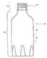
图1是用作制备模塑的容器的起始原料时的预成型坯;Figure 1 is a preform when used as a starting material for making a molded container;
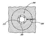
图2是图1的单层预成型坯的横截面;Figure 2 is a cross section of the single layer preform of Figure 1;
图3是多层预成型坯的横截面;Figure 3 is a cross-section of a multilayer preform;
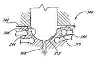
图4是多层预成型坯的另一个实施方案的横截面;Figure 4 is a cross-section of another embodiment of a multilayer preform;
图5是预成型坯的三层实施方案;Figure 5 is a three-layer embodiment of a preform;
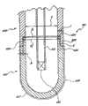
图6是在可以用于制备容器的类型的吹塑装置的模腔中的预成型坯的横截面;Figure 6 is a cross-section of a preform in the cavity of a blow molding device of the type that can be used to prepare containers;
图6A是吹塑装置的另一个实施方案的横截面;Figure 6A is a cross-section of another embodiment of a blow molding apparatus;
图7是容器的一个实施方案的侧视图;Figure 7 is a side view of one embodiment of the container;
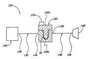
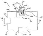
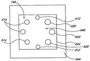
图8是温度控制系统的示意图;Fig. 8 is the schematic diagram of temperature control system;
图9是温度控制系统的示意图;Fig. 9 is the schematic diagram of temperature control system;
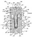
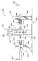
图10是可以用于制备优选的多层预成型坯的类型的注射模具的横截面;Figure 10 is a cross-section of an injection mold of the type that can be used to make a preferred multilayer preform;
图11是图10的模具沿直线11-11截取的横截面;Figure 11 is a cross-section taken along the line 11-11 of the mold of Figure 10;
图12是根据一个实施方案的模具的模腔部的横截面视图;Figure 12 is a cross-sectional view of a cavity portion of a mold according to one embodiment;
图13是图12的模腔部的另一个横截面视图;Figure 13 is another cross-sectional view of the cavity portion of Figure 12;
图14是具有高热传递基底端部的增强注射模具模芯的横截面;Figure 14 is a cross-section of a reinforced injection mold core with a high heat transfer base end;
图15是使用硬化材料部件、高传热材料部件和流体沟道的组合的注射模具的横截面;Figure 15 is a cross-section of an injection mold using a combination of hardened material parts, high heat transfer material parts and fluid channels;
图16和17是制备多层预成型坯的模塑装置的两个半部;Figures 16 and 17 are the two halves of a molding apparatus for making multilayer preforms;
图18和19是用于制备48个多层预成型坯的模塑装置的两个半部;Figures 18 and 19 are the two halves of a molding apparatus for making 48 multilayer preforms;
图20是带有部分地位于模塑模腔内的模芯的模具的示意性的透视图;Figure 20 is a schematic perspective view of a mold with a core partially positioned within a molding cavity;
图21是具有完全从模塑模腔中拔出的模芯的模具在旋转之前的透视图;Figure 21 is a perspective view of the mold with the core fully extracted from the molding cavity prior to rotation;
图22是用于模塑制品的模具的一部分的横截面图;Figure 22 is a cross-sectional view of a portion of a mold for molding an article;
图23是图22的模具沿着直线23-23截取的传热构件的横截面视图;23 is a cross-sectional view of the heat transfer member of the mold of FIG. 22 taken along line 23-23;
图24示出了根据一个实施方案的被配置成制备多层预成型坯的注塑机的正视图;Figure 24 shows a front view of an injection molding machine configured to make multilayer preforms, according to one embodiment;
图24A示出了根据另一个实施方案的被配置成制备多层预成型坯的注射模塑机的正视图;24A shows a front view of an injection molding machine configured to make multilayer preforms according to another embodiment;
图25示意性地说明了在其四个侧面上具有芯棒的旋转立方体的实施方案;Figure 25 schematically illustrates an embodiment of a rotating cube with mandrels on its four sides;
图26示意性地说明了根据一个实施方案的包含旋转活接头和冷却流体分配系统的立方体;以及Figure 26 schematically illustrates a cube containing a rotary union and cooling fluid distribution system, according to one embodiment; and
图27示意性地说明了根据另一个实施方案的包含旋转活接头和冷却流体分配系统的立方体。Figure 27 schematically illustrates a cube containing a rotary union and cooling fluid distribution system according to another embodiment.
优选实施方案详述DETAILED DESCRIPTION OF THE PREFERRED EMBODIMENT
本文中提到的所有专利和公开都通过引用将它们的全部内容结合到此。除本文进一步描述的以外,本文描述的一些实施方案、特征、系统、装置、材料、方法和技术在一些实施方案中可以与在下列专利中描述的实施方案、特征、系统、装置、材料、方法和技术中的任一个或多个相类似:美国专利6,109,006;6,808,820;6,528,546;6,312,641;6,391,408;6,352,426;6,676,883;7,261,551;7,303,387;美国专利申请09/745,013(美国公开号2002-0100566);10/168,496(美国公开号2003-0220036);09/844,820(美国公开号2003-0031814);10/090,471(美国公开号2003-0012904);10/395,899(美国公开号2004-0013833);10/614,731(美国公开号2004-0071885);10/705,748(美国公开号2004-0151937);11/108,342(美国公开号2006-0065992);11/108,345(美国公开号2006-0073294);11/108,607(美国公开号2006-0073298);11/512,002(美国公开号2007-0108668);11/546,654(美国公开号2007-0087131);在2004年4月16日提交的美国临时申请60/563,021;在2004年5月28日提交的美国临时申请60/575,231;在2004年7月7日提交的美国临时申请60/586,399;在2004年10月18日提交的美国临时申请60/620,160;在2004年10月22日提交的美国临时申请60/621,511;以及在2005年1月11日提交的美国临时申请60/643,008,所有这些专利或专利申请都通过引用将它们的全部内容结合到此。此外,本文描述的实施方案、特征、系统、装置、材料、方法和技术在一些实施方案中可以适用于或被应用于在上述专利和申请中公开的实施方案、特征、系统、装置、材料、方法和技术中的任一个或多个方面。A.一些优选材料的详细描述1.优选材料的一般描述All patents and publications mentioned herein are hereby incorporated by reference in their entirety. Except as further described herein, some of the embodiments, features, systems, devices, materials, methods and techniques described herein can in some embodiments be compared to the embodiments, features, systems, devices, materials, methods described in the following patents Similar to any one or more of the techniques: U.S. Patents 6,109,006; 6,808,820; 6,528,546; 6,312,641; 6,391,408; 6,352,426; (U.S. Publication No. 2003-0220036); 09/844,820 (U.S. Publication No. 2003-0031814); 10/090,471 (U.S. Publication No. 2003-0012904); 10/395,899 (U.S. Publication No. 2004-0013833); 11/108,342 (US Publication No. 2006-0065992); 11/108,345 (US Publication No. 2006-0073294); 11/108,607 (U.S. Publication No. 2006-0073298); 11/512,002 (U.S. Publication No. 2007-0108668); 11/546,654 (U.S. Publication No. 2007-0087131); U.S. Provisional Application 60/563,021 filed April 16, 2004; filed May 2004 U.S. Provisional Application 60/575,231 filed on 28th; U.S. Provisional Application 60/586,399 filed on July 7, 2004; U.S. Provisional Application 60/620,160 filed on October 18, 2004; US Provisional Application 60/621,511, filed; and US Provisional Application 60/643,008, filed January 11, 2005, all of which patents or patent applications are hereby incorporated by reference in their entirety. Furthermore, the embodiments, features, systems, devices, materials, methods and techniques described herein may in some embodiments be adapted or applied to the embodiments, features, systems, devices, materials, Any one or more aspects of methods and techniques. A.Detailed description of some
在本文中公开的预成型坯、由预成型坯制备的容器和/或其它制品可以包含一种或多种不同类型的热塑性材料,比如聚对苯二甲酸乙二醇酯(PET)。然而,预成型坯和其它模塑的制品可以包含一种或多种其它热塑性材料。在一个实施方案中,PET被用作聚酯基底。如本文使用的,“PET”包括但不限于改性的PET,以及共混有其它材料如IPA的PET。The preforms, containers made from the preforms, and/or other articles disclosed herein may comprise one or more different types of thermoplastic materials, such as polyethylene terephthalate (PET). However, preforms and other molded articles may contain one or more other thermoplastic materials. In one embodiment, PET is used as the polyester substrate. As used herein, "PET" includes, but is not limited to, modified PET, and PET blended with other materials such as IPA.
如本文使用的,术语“基底”是以它的通常意义使用的广义术语,并且包括其中“基底”指用于形成预成型坯的第一或最内层的材料的实施方案。其它合适的用于预成型坯、容器和/或其它可模塑制品的合适基底包括但不限于各种聚合物,比如聚酯(PET、PEN、PETG)、聚烯烃(PP和PE)、聚酰胺类(尼龙6、尼龙66)、聚碳酸酯类、聚乳酸(PLA)、丙烯酸类、聚苯乙烯类、环氧化物、接枝的聚合物和任何前述聚合物的共聚物或共混物。在一些实施方案中,基底材料可以是未用过的、使用之前、使用之后、再粉碎、回收的和/或它们的组合。As used herein, the term "substrate" is a broad term used in its ordinary sense, and includes embodiments wherein "substrate" refers to the material used to form the first or innermost layer of a preform. Other suitable suitable substrates for preforms, containers, and/or other moldable articles include, but are not limited to, various polymers such as polyesters (PET, PEN, PETG), polyolefins (PP and PE), poly Amides (nylon 6, nylon 66), polycarbonates, polylactic acid (PLA), acrylics, polystyrenes, epoxides, grafted polymers and copolymers or blends of any of the foregoing . In some embodiments, the substrate material can be virgin, pre-use, post-use, reshred, recycled, and/or combinations thereof.
用于预成型坯的一种合适的涂层或重叠模塑层是RPET。如本文使用的,术语“RPET”是广义的术语,是指但不限于未用过的、使用之前、使用之后、再粉碎和/或回收的PET。在一些实施方案中,用于涂层或其它重叠模塑层中的材料可以包括但不限于PET、RPET、其它未用过的和/或用过的聚酯、其它再回收材料,或它们的组合。可以在基底上涂布或以其它方式设置一个或多个层。这些添加的层在本文中可以交换地称作“涂层”、“重叠模塑层”、“重叠注射层”、“外层”或“第二层”。在一些实施方案中,这些层包括PET层、RPET层、其它再回收材料、阻隔层、UV保护层、氧清除层、氧阻隔层、二氧化碳清除层、二氧化碳阻隔层、耐水性涂层、泡沫层和/或特定应用或用途所需要或适宜的其它层。此外,任何涂层或基底层中可以包含很多添加剂。在本文中进一步描述这些类型的材料用的合适材料。One suitable coating or overmolding layer for preforms is RPET. As used herein, the term "RPET" is a broad term referring to, but not limited to, virgin, pre-use, post-use, reshredded and/or recycled PET. In some embodiments, materials used in coatings or other overmold layers may include, but are not limited to, PET, RPET, other virgin and/or used polyesters, other recycled materials, or their combination. One or more layers may be coated or otherwise disposed on the substrate. These added layers may be referred to interchangeably herein as "coatings," "overmolded layers," "overinjected layers," "outer layers," or "second layers." In some embodiments, these layers include PET layers, RPET layers, other recycled materials, barrier layers, UV protection layers, oxygen scavenging layers, oxygen barrier layers, carbon dioxide scavenging layers, carbon dioxide barrier layers, water resistant coatings, foam layers and/or other layers as may be desired or desirable for a particular application or use. Additionally, any number of additives may be included in any coating or base layer. Suitable materials for these types of materials are further described herein.
可用于气体阻隔层的材料的实例包括一种或多种的乙烯醇聚合物和共聚物(PVOH、EVOH、EVA)、热塑性环氧树脂,比如苯氧基类热塑性材料(包括羟基-官能的聚(酰胺醚类)、聚(羟基酰胺醚类)、酰胺-和羟基甲基官能化聚醚类、羟基-官能的聚醚类、羟基-官能的聚(醚磺酰胺类)、聚(羟基酯醚类)、羟基-苯氧基醚聚合物以及聚(羟基氨基醚类))、聚酯和共聚酯材料(PETG、PEN)、线型低密度聚乙烯(LLDPE)、聚(对苯二甲酸亚环己基二亚甲基酯)、聚乳酸(PLA)、聚碳酸酯类、聚乙醇酸(PGA)、聚乙烯亚胺、氨基甲酸酯类、丙烯酸类、聚苯乙烯、环烯烃、聚-4-甲基戊烯-1、聚(甲基丙烯酸甲酯)、丙烯腈、聚氯乙烯、聚偏二氯乙烯(PVDC)、苯乙烯丙烯腈、丙烯腈-丁二烯-苯乙烯、聚缩醛、聚对苯二甲酸丁二醇酯、聚砜、聚四-氟乙烯、聚1,2-二氧基苯甲酸四亚甲基酯,以及对苯二甲酸乙二醇酯和间苯二甲酸乙二醇酯的共聚物,以及上述任一种的共聚物和/或共混物。在一些实施方案中,优选气体阻隔层比基底层对氧和二氧化碳的渗透性更少。Examples of materials that can be used for the gas barrier layer include one or more vinyl alcohol polymers and copolymers (PVOH, EVOH, EVA), thermoplastic epoxies, such as phenoxy thermoplastics (including hydroxyl-functional poly (amide ethers), poly(hydroxyamide ethers), amide- and hydroxymethyl-functionalized polyethers, hydroxy-functional polyethers, hydroxy-functional poly(ether sulfonamides), poly(hydroxyesters ethers), hydroxy-phenoxyether polymers and poly(hydroxyaminoethers)), polyester and copolyester materials (PETG, PEN), linear low-density polyethylene (LLDPE), poly(terephthalene cyclohexylene dimethylene formate), polylactic acid (PLA), polycarbonate, polyglycolic acid (PGA), polyethyleneimine, urethane, acrylic, polystyrene, cycloolefin, poly -4-methylpentene-1, poly(methyl methacrylate), acrylonitrile, polyvinyl chloride, polyvinylidene chloride (PVDC), styrene acrylonitrile, acrylonitrile-butadiene-styrene, Polyacetal, polybutylene terephthalate, polysulfone, polytetrafluoroethylene,
可以用于耐水性层的材料的实例包括聚酯、丙烯酸类、(甲基)丙烯酸(烷基)聚合物和共聚物(EAA)、聚烯烃聚合物或共聚物(PP、PE)、(甲基)丙烯酸聚合物或共聚物、蜡(巴西棕榈蜡、石蜡、聚乙烯、聚丙烯和费-托合成过程中得到的蜡(Fischer-Tropsch))、石蜡类和/或类似材料。Examples of materials that can be used for the water resistant layer include polyester, acrylic, (meth)acrylic (alkyl) polymers and copolymers (EAA), polyolefin polymers or copolymers (PP, PE), (meth)acrylic (alkyl) polymers and copolymers (EAA), polyolefin polymers or copolymers (PP, PE), (form based) acrylic polymers or copolymers, waxes (carnauba, paraffin, polyethylene, polypropylene and Fischer-Tropsch), paraffins and/or similar materials.
在一些实施方案中,可以在预成型坯或其它制品的层中使用发泡材料或弹性材料。在一些实施方案中,发泡材料可以包含热塑性材料、热固性材料或聚合物材料,比如乙烯丙烯酸(“EAA”)、乙烯乙酸乙烯酯(“EVA”)、线型低密度聚乙烯(“LLDPE”)、聚对苯二甲酸乙二醇酯二元醇(PETG)、聚(羟基氨基醚类)(“PHAE”)、PET、聚乙烯、聚丙烯、聚苯乙烯(“PS”)、纸浆(例如,木材或纸的纤维浆、或混合有一种或多种聚合物的纸浆),它们的混合物,等。在一些实施方案中,这些材料混合有起泡剂,比如微球,或其它已知的起泡剂,这取决于所使用的确切的发泡材料。在一些实施方案中,可以使用的弹性体或塑性体材料包括聚烯烃弹性体(比如乙烯-丙烯橡胶)、聚烯烃塑性体、改性的聚烯烃弹性体(比如,乙烯、丙烯和苯乙烯的三元聚合物)、改性的聚烯烃塑性体、热塑性氨基甲酸酯弹性体、丙烯酸-烯烃共聚物弹性体、聚酯弹性体,以及它们的组合。In some embodiments, foamed or elastic materials may be used in the layers of the preform or other article. In some embodiments, the foamed material may comprise thermoplastic, thermoset, or polymeric materials such as ethylene acrylic acid ("EAA"), ethylene vinyl acetate ("EVA"), linear low density polyethylene ("LLDPE") ), polyethylene terephthalate glycol (PETG), poly(hydroxyamino ethers) (“PHAE”), PET, polyethylene, polypropylene, polystyrene (“PS”), pulp ( For example, fiber pulp of wood or paper, or pulp mixed with one or more polymers), mixtures thereof, and the like. In some embodiments, these materials are mixed with blowing agents, such as microspheres, or other known blowing agents, depending on the exact foaming material used. In some embodiments, elastomeric or plastomeric materials that can be used include polyolefin elastomers (such as ethylene-propylene rubber), polyolefin plastomers, modified polyolefin elastomers (such as ethylene, propylene, and styrene terpolymers), modified polyolefin plastomers, thermoplastic urethane elastomers, acrylic-olefin copolymer elastomers, polyester elastomers, and combinations thereof.
在一些实施方案中,可以将一些粘合剂材料添加至一个或多个层中,或可以在相邻层之间的粘结层中使用。合适的粘合剂材料包括聚烯烃、改性的聚烯烃组合物(例如,用极性基团接枝或改性,比如PPMA、PEMA)、聚乙烯亚胺(PEI)。在任何层中还可以使用粘合增强剂。合适的粘合增强剂包括锆盐和钛盐以及有机醛。In some embodiments, some adhesive material may be added to one or more layers, or may be used in a tie layer between adjacent layers. Suitable binder materials include polyolefins, modified polyolefin compositions (eg, grafted or modified with polar groups, such as PPMA, PEMA), polyethyleneimine (PEI). Adhesion enhancers may also be used in any of the layers. Suitable adhesion enhancers include zirconium and titanium salts and organic aldehydes.
一个或多个层还可以包含添加剂,比如纳米粒子阻隔材料、氧清除剂、UV吸收剂、着色剂、染料、颜料、耐磨损添加剂、填料、防-发泡/起泡剂等。这些之中,可以使用本领域普通技术人员已知的具有提供CO2阻隔、O2阻隔、UV保护、耐磨损性、抗发白性、耐冲击性、耐水性和/或耐化学性的能力的添加剂。气体阻隔添加剂的一个非限制性实例是间苯二酚(间-二羟基苯)的衍生物,比如间苯二酚二环氧甘油醚和羟基乙基醚间苯二酚。One or more layers may also contain additives such as nanoparticle barrier materials, oxygen scavengers, UV absorbers, colorants, dyes, pigments, antiwear additives, fillers, anti-foaming/foaming agents, and the like. Of these, those known to those of ordinary skill in the art to provideCO2 barrier,O2 barrier, UV protection, abrasion resistance, blush resistance, impact resistance, water resistance and/or chemical resistance can be used. Ability Additives. A non-limiting example of a gas barrier additive is a derivative of resorcinol (m-dihydroxybenzene), such as resorcinol diglycidyl ether and resorcinol hydroxyethyl ether.
合适的交联剂可以根据它们所添加到其中的树脂或材料的化学性和功能性来选取。例如,胺交联剂可以用于交联含有环氧基团的树脂。还可以使用固化增强剂,比如辐射吸收添加剂(例如,炭黑)和过渡金属。Suitable crosslinkers can be selected based on the chemistry and functionality of the resin or material to which they are added. For example, amine crosslinkers can be used to crosslink resins containing epoxy groups. Cure enhancers such as radiation absorbing additives (eg, carbon black) and transition metals can also be used.
在下列文献中提供了关于这些材料的其它公开:美国专利申请10/614,731(美国公开号2004-0071885);11/108,607(美国公开号2006-0073298);11/512,002(美国公开号2007-0108668);11/405,761(美国公开号2006-0292323);11/546,654(美国公开号2007-0087131);2007年4月18日提交的美国临时申请60/912,675,这些文献全都通过引用将它们的全部内容结合到此。B.附图详述Additional disclosures regarding these materials are provided in U.S. Patent Application 10/614,731 (U.S. Publication No. 2004-0071885); 11/108,607 (U.S. Publication No. 2006-0073298); 11/512,002 (U.S. ); 11/405,761 (U.S. Publication No. 2006-0292323); 11/546,654 (U.S. Publication No. 2007-0087131);
在一些实施方案中,描述一个或多个注射模具系统或装置。此外,还公开了由这些系统和装置制备的预成型坯和其它成形制品。本文中描述的制品可以是单层或多层(即,两层以上)。在一些实施方案中,制品可以是包装物,比如饮料器皿(包括预成型坯、容器、瓶子、封口件等)、箱子、纸盒、托盘、薄片等。In some embodiments, one or more injection molding systems or devices are described. Additionally, preforms and other shaped articles produced by these systems and apparatus are disclosed. The articles described herein can be single layer or multilayer (ie, more than two layers). In some embodiments, the article may be a package, such as a beverage vessel (including preforms, containers, bottles, closures, etc.), cases, cartons, trays, sheets, and the like.
本文公开的多层制品可以包含内层(例如,与容器的内容物接触的层),所述内层的材料是管理机构(例如,美国食品和药物管理局(Association))核准的材料或法规核准与食品(包括饮料)、药物、化妆品等接触的材料。在其它实施方案中,内层包含未经法规方案(scheme)核准的接触食品的一种或多种材料。第二层可以包含第二材料,其可以类似于或不同于形成内层的材料。如所论述的,这样的涂层或重叠模塑层可以包含未用过的PET、RPET和/或任何其它聚酯和/或其它类型的热塑性材料。制品可以具有与适宜或需要一样多的层。预期预成型坯或其它制品可以包含形成各种部分而不是“层”的一种或多种材料。The multilayer articles disclosed herein may comprise an inner layer (e.g., a layer in contact with the contents of the container) of a material approved by a regulatory agency (e.g., the U.S. Food and Drug Administration (Association)) or by regulation Approval for materials that come into contact with food (including beverages), drugs, cosmetics, etc. In other embodiments, the inner layer comprises one or more materials that are not approved for food contact by a regulatory scheme. The second layer may comprise a second material, which may be similar to or different from the material forming the inner layer. As discussed, such coatings or overmold layers may comprise virgin PET, RPET and/or any other polyester and/or other types of thermoplastic materials. An article can have as many layers as is convenient or necessary. It is contemplated that a preform or other article may comprise one or more materials that form various parts rather than "layers."
参考图1,说明优选的单层预成型坯30。预成型坯优选由FDA核准的材料比如未用过的PET制备,并且可以具有各种形状和尺寸中的任何一种。图1所示的预成型坯是将形成碳酸饮料瓶(例如,16盎司瓶)或其它容器的类型。在一些实施方案中,如本文所论述的,预成型坯和其它模塑制品可以包含一个或多个PET、RPET和/或其它回收材料的重叠模塑层或涂层。在其它布置中,除了RPET层,或代替RPET层之外,预成型坯可以具有氧和/或二氧化碳阻隔层。然而,如本领域技术人员理解的,可以取决于所需要的构造、特征和最终制品的用途而使用其它预成型坯构造。单层预成型坯30可以由本文所公开的方法制备。Referring to Figure 1, a preferred
参考图2,示出了图1的预成型坯30的横截面。预成型坯30具有整体形成的颈部32和躯体部34(即,作为单一或统一的结构体)。有利地,当吹塑成瓶时,预成型坯的整体布置相比于由分开的颈部和躯体部连接在一起而构成的预成型坯,提供了更大的尺寸稳定性并且改善了物理性质。然而,预成型坯可以包含结合在一起的颈部和躯体部。Referring to FIG. 2 , a cross-section of the
在一些实施方案中,颈部32开始于预成型坯30的开口36至内部,以及延伸到并且包括支撑环38或其它结构。颈部32进一步的特征在于存在螺纹40,这提供了紧固用于预成型坯30所制备的瓶的瓶帽的方式。备选地,颈部32可以被配置成啮合封闭件或瓶帽(例如,冠状封闭件、软木塞(天然或人造的)、咬合帽、穿孔密封件和/或类似物)。躯体部34是细长并且圆柱形结构体,其从颈部32向下延伸并且在圆形端帽42中结束。预成型坯厚度44将取决于预成型坯30的整个长度,以及所得容器的壁厚和整体尺寸。In some embodiments,
参考图3,公开了多层预成型坯50的一个实施方案的横截面。所示出的预成型坯50类似于图1和2的预成型坯30,包括颈部32和躯体部34。层52可以设置在躯体部34的整个表面周围,终止于支撑环38的底部。在图示的实施方案中的涂层52没有延伸到颈部32,也没有出现在预成型坯的内表面54上,所述的预成型坯优选由一种或多种FDA-核准材料比如PET制备。涂层52可以包含单一材料或至少两种材料的若干微层。作为实例,预成型坯的底部的壁可以具有3.2毫米的厚度;颈部的壁可以具有约3毫米的横截面尺寸;以及该材料被涂敷至约0.3毫米的厚度。涂层或重叠模塑层52可以包含PET、RPET、阻隔材料、泡沫体和/或适合于形成预成型坯的外表面的其它聚合物材料。Referring to FIG. 3 , a cross-section of one embodiment of a
预成型坯的总厚度56等于开始的未涂布的预成型坯39的厚度加上外层或涂层52的厚度58,并且取决于所得容器(例如,碳酸饮料瓶)的总尺寸和所需的涂布厚度。然而,预成型坯50可以具有任何厚度,该厚度取决于由预成型坯50形成的容器的适宜或需要的热性质、结构性质和/或其它类型的性质。预成型坯和容器可以包含具有宽泛的各种相对厚度的层。The
参考图4,显示了多层预成型坯60的一个实施方案的横截面。已涂布的预成型坯60和图3的已涂布的预成型坯50之间的主要差异是在端帽42的区域中的两层的相对厚度。图3的预成型坯50具有外层52,所述外层52通常比预成型坯的内层的厚度在预成型坯的整个躯体部到处更薄。然而,预成型坯60的外层52在接近端帽42的62处比在壁部66中的64处更厚,并且相反地,在端帽42的区域中,内侧的厚度在壁部66的68处比在70处更大。如本文所述的,当在重叠模塑工序中涂敷于初始预成型坯以制备涂布的预成型坯时,这种预成型坯设计可能是有利的。这种布置可能提供一些优点,包括但不限于减少总的模塑循环时间。层52可以是均匀的或它可以包含多个微层。然而,在其它实施方案中,预成型坯的各个层的相对厚度可以不同于本文所论述和/或示出的。Referring to FIG. 4 , a cross-section of one embodiment of a
多层预成型坯和容器可以包含具有宽泛的各种相对厚度的层。鉴于本公开内容,给定层的厚度以及整个预成型坯或容器的厚度,无论是在给定点或在整个容器上,都可以进行选择以适合用于容器的特定模塑工艺或特定最终用途。此外,本文中如图3所论述的,预成型坯或容器的外层或重叠模塑层可以包含单一材料,或包含两种或更多种材料的若干微层。Multilayer preforms and containers may contain layers having a wide variety of relative thicknesses. In light of this disclosure, the thickness of a given layer, as well as the thickness of the overall preform or container, whether at a given point or over the entire container, can be selected to suit a particular molding process for the container or a particular end use. Furthermore, as discussed herein with respect to Figure 3, the outer or overmolded layer of the preform or container may comprise a single material, or several microlayers comprising two or more materials.
图5示出了三层预成型坯72的一个实施方案。多层预成型坯的所述布置可以通过将两个涂层或重叠模塑层74和76放置在单层预成型坯如图1所示的预成型坯30上进行制备。One embodiment of a three-
在通过比如下面详细论述的方法和装置制备预成型坯如图3所示的预成型坯之后,可以将其进行拉伸吹塑工艺。因此,参考图6,可以将多层预成型坯50放置在具有对应于所需容器形状的模腔的模具80中。然后,加热预成型坯并且通过拉伸和/或迫使空气进入到预成型坯50的内部以填充模具80内的模腔而膨胀,从而产生容器82(图7)。吹塑操作通常限制于具有颈部32的预成型坯的躯体部34,从而保持如预成型坯中的原始构造,所述颈部32包含螺纹、防盗环和支撑环。单层和多层容器可以通过分别拉伸吹塑单层和多层预成型坯而形成。After a preform as shown in Figure 3 has been prepared by methods and apparatus such as those discussed in detail below, it can be subjected to a stretch blow molding process. Thus, referring to FIG. 6, the
图6A示出了拉伸吹塑模具,该拉伸吹塑模具被配置成改进循环时间和热效率。模具80A的壁的温度可以精确地控制以在整个吹塑的容器上的所需温度分布。Figure 6A shows a stretch blow mold configured to improve cycle time and thermal efficiency. The temperature of the walls of the mold 80A can be precisely controlled to obtain a desired temperature distribution throughout the blown container.
参考图7,公开了根据优选实施方案的容器82的一个实施方案,比如可以通过吹塑图3的多层预成型坯50而制备的容器。容器82具有对应于图3的预成型坯50的颈部和躯体部的颈部32和躯体部34。颈部32进一步的特征在于存在螺纹40,而螺纹40提供了一种将瓶帽紧固到容器上的手段。Referring to FIG. 7 , an embodiment of a
在一些实施方案中,外层或重叠模塑层84覆盖容器82的整个躯体部34的外部,停止于支撑环38的正下方。容器的内表面86可以包含FDA-核准的材料,优选PET,并且可以保持未涂布,以使得仅有内表面86与饮料或食品接触。在可以被用作碳酸饮料容器的一些实施方案中,该层的厚度87优选为约0.508mm-1.524mm(0.020-0.060英寸),更优选约0.762mm-1.016mm(0.030-0.040英寸);PET层的厚度88优选为约2.032mm-4.064mm(0.080-0.160英寸),更优选约2.54mm-3.556mm(0.100-0.140英寸);并且多层容器82的总壁厚90优选为约3.556mm-4,562mm(0.140-0.180英寸),更优选约3.82mm-4.318mm(0.150-0.170英寸)。在一些实施方案中,容器82的壁可以占内PET层的厚度的大部分。在一些布置中,容器82可以是单层容器。例如,容器82可以通过拉伸吹塑图1的预成型坯30而制备。在2005年4月18日提交的名称为MONOAND MULTI-LAYER ARTICLES AND INJECTION METHODS OFMAKING THE SAME的美国专利申请11/108,345序列号中公开了可以由本文公开的系统进行制备的其它制品和相关的材料,该美国专利申请11/108,345序列号已经以美国公开号2006/0073294进行了公开。C.注射模塑方法、装置和系统In some embodiments, the outer or
图8示意性地示出了根据一个实施方案的温度控制系统120。温度控制系统120的所示布置是开放式回路系统。温度控制系统120可以用于控制模塑装置122的温度。模塑装置122可以被配置成模塑单一制品或多个制品。模塑装置122可以被配置成形成任何形状和构造的制品。例如,模塑装置122可以被设计成制备预成型坯、容器和其它通过模具形成的制品。在一些实施方案中,模塑装置122可以是拉伸吹塑装置、注射模塑装置、压缩模塑装置、热模塑或热成型系统、真空形型系统等。模塑装置122可以包含或可以不包含高传热材料。一些示例性的温度控制系统使用了用于在模塑加工过程中控制模塑装置的温度的工作流体或其它手段。图示的温度控制系统120具有通过模塑装置122的工作流体以控制在模塑装置122中的聚合物的温度。工作流体可以取决于特定应用而处于宽范围的温度。Figure 8 schematically illustrates a
所示出的模塑装置122包含多个模具部分,所述多个模具部分协作以限定模塑模腔。在一些实施方案中,模塑装置122包含可以在开启位置和闭合位置之间移动的模具部122a和模具部122b。模具部122a和模具部122b可以形成具有用来制备预成型坯如所示出的预成型坯30大小和构造的模具模腔。模塑装置122还可以被设计用于形成多层预成型坯或其它制品的层。温度控制系统120可以用于选择性控制模塑装置122的温度以减少循环时间,产生所需的涂面(finish)(例如,晶体的量),提高模具寿命,改善预成型坯质量等。The
继续参考图8中所示的实施方案,温度控制系统120包括流体管线130,140。流体管线130连接流体源126至模塑装置122,并且流体管线140连接模塑装置122至排放系统148。流体管线可以限定工作流体通过系统120的流动路径。Continuing with the embodiment shown in FIG. 8 , the
如本文使用的,术语“流体源”是广义的术语,并且以其一般的意义使用,且是指但不限于装置,所述的装置适合于提供可以被用于保持模塑装置122在合适的温度的流体。在各种实施方案中,流体源可以包含瓶、罐、压缩机系统,或任何其它合适的流体分配装置。流体源126可以包含一定量的液体,优选制冷剂。例如,流体源126可以包含一种或多种制冷剂,比如氟利昂、制冷剂(Refrigerant)12、制冷剂22、制冷剂134a等。流体源126还可以包含低温流体,比如液体二氧化碳(CO2)或氮(N2)。在一些实施方案中,工作流体可以便利地在室温储存。例如,CO2或氮当在足够压力下时在典型的室温为液体。在一些非限制性实施方案中,流体源126中的储存流体的压力通常将在约40巴至约80巴的范围内。在一些实施方案中,流体源126是瓶子,并且在预成型坯模塑过程中,瓶子中的压力将随着来自瓶子的流体被消耗而降低。如下面所述,流体源126可以包含足量的流体,使得模塑装置122可以被冷却多个循环。流体源126可以具有调节器以控制流向流体管线130的流体的流量,并且可以包含压缩机,该压缩机可以对流体管线130中的流体提供压力。任选地,温度控制系统的工作流体可以包含上述流体中的两种或更多种的组合,以实现工作流体的所需的热特性。例如,在一些实施方案中,工作流体的组分的百分比可以基于所需温度和压力选择,以使得工作流体的组分不固化。其它工作流体比如水还可以被用于控制模塑装置的温度。当前,可以使用制冷剂,以与非-制冷剂比如水相比,更快速地加热和/或冷却模塑装置和相关的模塑制品。As used herein, the term "fluid source" is a broad term and is used in its ordinary sense, and refers to, but is not limited to, a device suitable for providing fluid that can be used to hold the
如本文使用的,术语“制冷剂”是广义的术语,并且以其一般意义使用,且是指但不限于非低温制冷剂(例如,氟利昂)和低温制冷剂。如本文使用的,术语“低温制冷剂”是广义术语,并且以其一般意义使用,且是指但不限于低温流体。如本文使用的,术语“低温流体”是指当流体处于液体状态时,在约5巴压力下,具有约-50℃的最大沸点的流体。在一些非限制性实施方案中,低温流体可以包含CO2、N2、氦、它们的组合等。在一些实施方案中,低温制冷剂是在约1.013巴下,沸点高于约-100℃的高温范围的低温流体。在一些实施方案中,低温制冷剂是沸点在约-100℃和-200℃之间的中温范围的低温流体。在一些实施方案中,低温制冷剂是在约1.013巴下沸点低于约-200℃的低温范围的低温流体。As used herein, the term "refrigerant" is a broad term and is used in its ordinary sense, and refers to, but is not limited to, non-cryogenic refrigerants (eg, Freon) and cryogenic refrigerants. As used herein, the term "cryogenic refrigerant" is a broad term and is used in its ordinary sense, and refers to, but is not limited to, low temperature fluids. As used herein, the term "cryogenic fluid" refers to a fluid having a maximum boiling point of about -50°C at a pressure of about 5 bar when the fluid is in the liquid state. In some non-limiting embodiments, the cryogenic fluid may compriseCO2 ,N2 , helium, combinations thereof, and the like. In some embodiments, the cryogenic refrigerant is a cryogenic fluid having a boiling point above about -100°C in the high temperature range at about 1.013 bar. In some embodiments, the cryogenic refrigerant is a medium temperature range cryogenic fluid boiling between about -100°C and -200°C. In some embodiments, the cryogenic refrigerant is a cryogenic fluid in the low temperature range having a boiling point below about -200°C at about 1.013 bar.
使用非低温流体的温度控制系统的热负荷容量比使用低温流体的温度控制系统的热负荷容量低得多。此外,非低温制冷剂在其达到模具的临界部分之前可以失去其有效的冷却能力。例如,氟利昂制冷剂可以在其通过膨胀阀之后但是在其达到临界模具位置之前,被加热并且完全气化,因而可能没有有效地冷却模具表面。使用低温流体的温度控制系统可以提供对模塑装置的模塑表面的快速冷却和/或加热,以减少循环时间并且提高模具输出。The heat load capacity of a temperature control system using a non-cryogenic fluid is much lower than that of a temperature control system using a cryogenic fluid. Furthermore, non-cryogenic refrigerants can lose their effective cooling capacity before they reach critical parts of the mould. For example, a freon refrigerant may be heated and completely vaporized after it passes the expansion valve but before it reaches the critical mold location, and thus may not cool the mold surface effectively. A temperature control system using a cryogenic fluid can provide rapid cooling and/or heating of the molding surfaces of the molding apparatus to reduce cycle times and increase mold output.
在一个实施方案中,将流体管线130的流体源进口128连接到流体源126上,并且流体管线130具有通往模塑装置122的出口134。来自流体源126的流体可以通过流体源进口128进入到流体管线130,并且出口134流出到模塑装置122。流体管线130是导管,比如加压流体可以在其中通过的管或软管。例如,在图8所示的实施方案中,在流体管线130中的流体是在约40巴至约80巴的压力下的液体制冷剂。In one embodiment, a
来自流体管线130的流体经过模塑装置122以控制模塑装置122的温度。在一些实施方案中,流体经过一个或多个位于模塑装置122的上游或之内的流动控制装置(例如,减压元件、阀等)。流动控制装置接收高压的流体(优选液体)并且将低压和低温流体(例如,气体或气体/液体混合物)输出至一个或多个在模塑装置122中的流动通道。如图10中所示,例如,流体可以通过多个减压元件212,进入多个流体通道或沟道204中,以选择性控制预成型坯的温度。循环通过图10的模塑装置的流体冷却温的熔体以形成多层预成型坯。Fluid from
如本文使用的,术语“减压元件”是广义术语并且以其一般意义使用,且是指但不限于被配置成减小工作流体的压力的装置。在一些实施方案中,减压元件可以将工作流体的压力减小至等于或小于工作流体的汽化压力的压力。工作流体可以包含制冷剂(例如,低温制冷剂或非低温制冷剂)。在一些实施方案中,减压元件是压力减小或膨胀阀的形式,其引起通过其中的工作流体的至少一部分汽化。减压元件可以具有固定的孔口或可变化的孔口。在一些实施方案中,减压元件可以是喷嘴阀,针阀、焦耳-汤姆孙(Joule-Thomson)膨胀阀或任何适合于提供所需压降的其它合适的阀。例如,焦耳-汤姆孙膨胀阀可以从流体的膨胀中回收工作能量,从而产生更低的下游温度。在一些实施方案中,减压元件将有效量的工作流体(例如,低温流体)汽化以降低工作流体的温度,使得工作流体可以有效率地冷却模具内的制品,以形成制品的尺寸稳定的外表面。在一些实施方案中,减压元件可以用流动调节元件(例如,阀系统)代替,尤其是如果工作流体是非-制冷剂如水的情况下。As used herein, the term "pressure relief element" is a broad term and used in its ordinary sense, and refers to, but is not limited to, a device configured to reduce the pressure of a working fluid. In some embodiments, the pressure reducing element can reduce the pressure of the working fluid to a pressure equal to or less than the vaporization pressure of the working fluid. The working fluid may contain a refrigerant (eg, a cryogenic refrigerant or a non-cryogenic refrigerant). In some embodiments, the pressure reducing element is in the form of a pressure reducing or expansion valve that causes vaporization of at least a portion of the working fluid passing therethrough. The pressure relief element can have a fixed orifice or a variable orifice. In some embodiments, the pressure reducing element may be a nozzle valve, a needle valve, a Joule-Thomson expansion valve, or any other suitable valve suitable to provide the desired pressure drop. For example, a Joule-Thomson expansion valve recovers operating energy from the expansion of the fluid, resulting in lower downstream temperatures. In some embodiments, the pressure relief element vaporizes an effective amount of the working fluid (eg, cryogenic fluid) to reduce the temperature of the working fluid so that the working fluid can efficiently cool the article within the mold to form a dimensionally stable outer surface of the article. surface. In some embodiments, the pressure reducing element may be replaced with a flow regulating element (eg, a valve system), especially if the working fluid is a non-refrigerant such as water.
再参考图8,在工作流体经过模塑装置122之后,流体流过进口136并且经过流体管线140,从出口144流到排放系统148。流体管线140是导管,比如加压流体可以在其中通过的管或软管。在一些实施方案中,在流体管线140中的流体处于低于约10巴、5巴、3巴、2巴并且包括这些压力在内的范围内的压力。当然,工作流体的压力可以根据应用而不同。Referring again to FIG. 8 , after the working fluid passes through
排放系统148可以接收和释放来自流体管线140的流体。排放系统148可以包含一个或多个阀,所述阀可以控制在流体管线140中的流体的压力以及从温度控制系统120中放出的流体的量。排放系统148可以包含一个或多个风扇和/或通风口,以进一步确保流体适当地经过温度控制系统120。优选地,流体是通过排放系统148排放到大气中的气体的形式。因此,来自流体源126的流体通过流体管线130,模塑装置122、流体管线140并且从排放系统148进入到大气中。优选地,温度控制系统120的工作流体是制冷剂,包括比如氮、氢或它们的组合的低温制冷剂。这些流体可以简便地排出到大气中,而不像一些其它可能不利地影响环境的制冷剂。
图9示出了用于控制模塑装置的温度的温度控制系统的另一个实施方案。除了下面进一步详述的之外,这样的温度控制系统可以通常地类似于图8所示的实施方案。在可能的情况下,图8和9的类似或相同的元件用相同的标记数字标记。Figure 9 shows another embodiment of a temperature control system for controlling the temperature of a molding apparatus. Such a temperature control system may generally be similar to the embodiment shown in FIG. 8, except as further detailed below. Where possible, similar or identical elements of FIGS. 8 and 9 are labeled with the same reference numerals.
图9示意性地说明了温度控制系统150,该温度控制系统150是封闭式回路系统,被设计用以在预成型坯制造过程中控制模塑装置122的温度。温度控制系统150具有与模塑装置122连通的流体源152。模塑装置122与单元156连通,该单元156与流体源152连通。为了冷却模塑装置122,工作流体可以按箭头所示的顺时针方向流动。Figure 9 schematically illustrates a
将流体源152连接到流体管线166的出口170上,并且连接到流体管线130的源进口128上。流体源152接收来自流体管线166的流体,并且将流体释放到流体管线130。流体源152可以在制备循环之前、过程中和/或之后,储存工作流体。
如图9所示,将流体管线130以上述的方式连接到流体源152和模塑装置122上。流体管线140与模塑装置122和单元156流体连通。将管线140的模具进口136连接到模塑装置122上,并且将管线140的出口144连接到单元156上。流体从模塑装置122流向进口136,并且通过流体管线140达到出口144。然后,流体通过出口144并进入单元156。As shown in FIG. 9,
单元156可以重新调节流体,使得流体可以被重新输送至模塑装置122,以连续流动通过温度控制系统150。单元156可以包括压缩机和/或热交换器。流体可以流过对流体加压的压缩机,然后流过热交换器(例如,冷凝器),热交换器降低了压缩流体的温度。在一些情况下,术语“热交换器”和“冷凝器”在本文中可以交换使用。优选地,单元156将低温液体输出到流体管线166的进口168。因此,来自单元156的流体可以流过流体管线166,经由出口170进入流体源152。
单元156可以改变对模塑装置122以及设置在其内的模塑制品加热的工作方式。工作流体可以逆时针方向经过温度控制系统150以加热模塑装置122。在一个实施方案中,单元156接收来自流体管线166的冷却流体(优选液体),并且释放与冷却液体相比为高温的气体或气/液混合物至流体管线140。高温流体可以加热模塑装置122以及设置在其内的制品。因此,单元156可以包括用于加热工作流体的蒸发器和/或压缩机。因此,必要时,单元156可以用于改变加热或冷却模塑装置122的工作模式。The
继续参考图9,温度控制系统150可以冷却模塑装置122的至少一部分,进而冷却在模塑装置122.中的塑料。在一个实施方案中,流体源152释放制冷剂比如低温流体(优选液体二氧化碳或氮)至流体管线130和模塑装置122。With continued reference to FIG. 9 , the
液体通过模塑装置122的一部分,并且释放到一个或多个减压元件212(参见图10)。减压元件212优选接收在高压的液体并且向模塑装置122的沟道中输出低温的流体(例如,气体或气/液混合物)。减压元件212可以降低通过其中的工作流体的温度。流体通过并且冷却模塑装置122的部分,由此冷却模塑装置中的聚合物。The liquid passes through a portion of
如图9所示,模塑装置122释放已加热的流体至流体管线140,进而释放该流体到起着压缩机和冷凝器作用的单元156。单元156将低温液体形式的流体输出到流体管线166和源152中。As shown in FIG. 9,
在一些实施方案中,包括图9所示的实施方案,温度控制系统150可以具有任选的反馈系统231,以将来自模塑装置122的已加热流体释放返回到模塑装置122中,并且穿过该模塑装置122。在操作中,在流体管线140中的流体通过反馈系统231,经由反馈管线232到达模塑装置122。优选地,在反馈管线232中的流体的温度高于在流体管线130中的流体的温度。模塑装置122的不同部分可以通过使用来自流体管线130和反馈管线232的流体保持在不同的温度。在反馈管线中的流体可以处于或可以不处于沉积到模塑装置内的熔体的温度。可以沿着管线130,232设置一个或多个阀系统,以调节通过模塑装置122的流体的流动。在一些实施方案中,当从源152至模塑装置122的流体流动减少或停止时,可以通过利用来自反馈管线232的流体来进行模塑装置122的加热。在一些实施方案中,可以利用来自反馈管线232的已加热的流体以降低模塑装置122的熔体的冷却速率,从而,例如在模塑制品中产生高的结晶程度。通过例如在不同温度的工作流体,可以在模具中实现不同的温度分布。In some embodiments, including the embodiment shown in FIG. 9, the
如上所述,温度控制系统150还可以通过使工作流体以逆时针方向流动,而加热模塑装置122的至少一部分。在一个实施方案中,流体源152可以将流体释放到流体管线166,而流体管线166将该流体释放到单元156。单元156可以起着压缩机的作用,并且可以提高工作流体的温度。在一些实施方案中,单元156可以接收来自管线162的流体(例如,两相工作流体)。两相工作流体的温度可以经由单元156升高,然后释放到管线140。As noted above, the
单元156将已加热的流体(例如,高温气体或气/液混合物)释放到流体管线140。然后,将流体释放到并且流过模塑装置122。流过模塑装置122中的通道的流体加热模具的一个或多个部分,进而加热模塑装置122中的聚合物或降低模塑装置122中的聚合物的冷却速率。流体当其通过模塑装置122时被冷却,并且释放到流体管线130,而流体管线130将已冷却的流体输送到流体源152。然后,如上所述,流体源152将流体释放到流体管线166。因此,流体以一个方向通过温度控制系统150,从而冷却模塑装置122,并且在反方向流过温度控制系统150,以加热模塑装置122。此外,必要时,流体的流动在预成型坯的制备过程中可能一次或多次颠倒,从而反复加热(例如,降低熔体的冷却速率)和冷却模具。
温度控制系统的流体源可以包括多种流体源。每一种流体源都可以包含不同的工作流体。例如,尽管没有示出,但是图9的温度控制系统150可以具有包含第二流体的第二流体源。如上所论述的,第二流体的冷冻点可以高于来自第一流体源152的汽化流体的温度。预期,可以在本文描述的任何流体系统中均可添加另外的流体源。因此,可以使用任何数量的流体源和工作流体以控制模塑装置的温度。应当理解,对于本文所公开的模塑装置或系统的任何实施方案,均可以在冷却沟道或其它导管中包括减压阀或其它元件。温度控制系统的其它实施方案公开在美国专利7,303,387中,该专利的名称为METHODS AND SYSTEMS FORCONTROLLING MOLD TEMPERATURES,并且通过引用将其结合到此。The fluid source for the temperature control system may include a variety of fluid sources. Each fluid source can contain a different working fluid. For example, although not shown, the
本领域的普通技术人员根据本文所描述的原理,可以将本文所公开的或通过引用结合在此的温度控制系统的特征、组件、系统、子系统、材料和方法进行组合和配合。此外,必要时,可以向温度控制系统中增加一个或多个止回阀、压力传感器、流动调节器、流体管线,温度传感器、检测器等。Those of ordinary skill in the art can combine and coordinate the features, components, systems, subsystems, materials and methods of the temperature control systems disclosed herein or incorporated by reference in accordance with the principles described herein. In addition, one or more check valves, pressure sensors, flow regulators, fluid lines, temperature sensors, detectors, etc. may be added to the temperature control system as necessary.
单层和多层制品(包括包装,比如封闭件、预成型坯、容器、瓶)可以通过注射模塑工艺形成。制备多层制品的一种方法在本文中被称作重叠模塑。多层预成型坯可以通过重叠模塑形成,所述重叠模塑通过例如注射-重叠-注射(″IOI″)工艺进行。该名称是指利用注射模塑在现有的预成型坯或基底上注射一层或多层的材料的程序,现有的预成型坯或基底本身优选通过注射模塑形成。术语“重叠注射”和“重叠模塑”在本文中被用于描述在现有预成型坯上注射材料层的模塑工艺。在特别优选的实施方案中,在下面的预成型坯还没有完全被冷却的时候进行重叠注射工艺。重叠注射可以用于在单层或多层预成型坯上设置的一个或多个另外的材料层,比如含有PET、RPET、其它回收材料、阻隔材料、回收PET、发泡材料或其它材料的那些层。Single-layer and multi-layer articles (including packaging, such as closures, preforms, containers, bottles) can be formed by the injection molding process. One method of making multilayer articles is referred to herein as overmolding. Multilayer preforms may be formed by overmolding by, for example, an injection-over-injection ("IOI") process. The name refers to the procedure of using injection molding to inject one or more layers of material onto an existing preform or substrate, which is itself preferably formed by injection moulding. The terms "overinjection" and "overmolding" are used herein to describe the molding process of injecting a layer of material over an existing preform. In a particularly preferred embodiment, the overinjection process is carried out while the underlying preform has not yet been completely cooled. Over-injection can be used to place one or more additional material layers on single or multi-layer preforms, such as those containing PET, RPET, other recycled materials, barrier materials, recycled PET, foamed materials, or other materials layer.
可以使用注射模塑以在基底((例如,底层)上设置一种或多种材料的一个或多个层,比如含有层状材料、PP、发泡材料、PET(包括回收PET、未用过的PET)、阻隔材料、苯氧基类热塑性材料、上述这些材料的组合和/或本文所描述的其它材料的层。在一些非限制性的示例实施方案中,基底是预成型坯的形式,所述预成型坯优选具有适合于接触食品的内表面。温度控制系统可以用于控制由这些模塑工艺形成的预成型坯的温度。如下面所详述的,在形成单一的单层预成型坯时,也可以使用温度控制系统。Injection molding can be used to place one or more layers of one or more materials on a substrate (e.g., a base layer), such as layered materials, PP, foamed materials, PET (including recycled PET, virgin PET), barrier materials, phenoxy-based thermoplastics, combinations of these materials, and/or layers of other materials described herein. In some non-limiting exemplary embodiments, the substrate is in the form of a preform, The preform preferably has an inner surface suitable for food contact. A temperature control system can be used to control the temperature of the preform formed by these molding processes. As detailed below, when forming a single monolayer preform When blanking, a temperature control system can also be used.
通过模塑工艺制成的制品可以包含一个或多个层或者部分,其具有下列优点特征中的一项或多项:RPET、PET或其它回收材料的一个或多个外层,绝缘层,阻隔层,食品接触层、非-香味筛除层(non-flavor scalping layer)、高强度层、适应层、粘结层、气体清涂层、适合于热灌装应用的层或部分、具有适合于挤出的熔体强度的层。在一个实施方案中,单层或多层材料包含下列材料中的一种或多种:PET(包括回收的(例如,RPET)和/或未用过的PET)、PETG、泡沫体、聚丙烯、苯氧基类热塑性材料、聚烯烃、苯氧基-聚烯烃热塑性共混物、和/或它们的组合。出于方便起见,制品主要相对于预成型坯和容器进行描述。Articles produced by the molding process may contain one or more layers or sections that have one or more of the following advantageous features: one or more outer layers of RPET, PET or other recycled material, insulation, barrier layer, food contact layer, non-flavor scaling layer (non-flavor scaling layer), high strength layer, adaptation layer, tie layer, gas clear layer, layer or part suitable for hot filling application, with suitable Extruded melt-strength layers. In one embodiment, the single or multilayer material comprises one or more of the following materials: PET (including recycled (e.g., RPET) and/or virgin PET), PETG, foam, polypropylene , phenoxy-based thermoplastics, polyolefins, phenoxy-polyolefin thermoplastic blends, and/or combinations thereof. For convenience, articles will be described primarily with respect to preforms and containers.
图10示出了在使用重叠模塑方法中使用的模塑装置132的一个实施方案。模塑装置132可以在预成型坯30上形成层,从而形成多层预成型坯,比如图3的预成型坯50。在本文中描述的温度控制系统可以被用于控制模塑装置132以及本文中描述的其它模具的温度。Figure 10 shows one embodiment of a
如所示,模塑装置132可以包括两个半部,模腔部192和模芯部194。模腔部192包括放置预成型坯的模腔。模芯部194和模腔部192可以在闭合位置和开启位置之间移动。预成型坯可以是单层预成型坯(图示)或多层预成型坯。预成型坯30被保持在模芯部194和模腔部192的凸缘196之间的适当位置上,其中模芯部194对预成型坯的顶部施加压力并且支撑环38靠在凸缘196上。因此,从预成型坯30的躯体部将预成型坯30的颈部32密封起来(sealed off)。预成型坯30的内部是模芯198。由于预成型坯30位于模塑装置132中,因此预成型坯30的躯体部被空隙空间200完全包围。空间200由预成型坯30的外表面以及模腔部192的模腔模塑表面203形成。这样的布置的预成型坯在随后的注射程序中起着内模具模芯的作用,其中重叠模塑材料的熔体被注射通过浇口202进入到空隙空间200,以形成预成型坯的外层。As shown,
如所论述的,模腔部192和/或模芯部194具有一个或多个温度控制元件204。温度控制元件204是用于控制熔体和预成型坯30的温度的多个通道或沟道的形式。流过沟道204的流体例如可以冷却模塑装置132,进而冷却被注射的熔体。在图10所示的实施方案中,模腔部192具有多个沟道204,而模芯部194也具有多个沟道206。多个减压元件212位于沟道204,206的上游。减压元件212位于模腔部192和模芯部194之内。然而,减压元件212可以位于模腔部192和/或模芯部194的外部。在所示的实施方案中,存在分别将流体释放到沟道206,204的上出口134和下出口134。As discussed,
继续参考图10,模具出口134可以具有与减压元件212流体连通的流动调节器214。流动调节器214可以是具有选择性控制往沟道204的流体的流动的阀系统。多个导管216可以提供流动调节器214和减压元件212之间的流体流动。每一个流动调节器214都可以选择性地允许或抑制流体从出口134往导管216以及往模塑装置132的流动。在一个实施方案中,流动调节器214可以是用电或空气作用制动的电磁阀,以允许或抑制通往模塑装置132的流动。在不同的其它实施方案中,流动调节器214可以是闸门阀、球阀或其它可以控制流体的流动的合适装置。控制器(例如,图9的控制器218)可以掌握流动调节器214以允许或抑制流体通往沟道(例如,沟道204和/或206)的流动。流动调节器214可以停止流过模塑装置132的流体的流动,以进行间歇式流体流动。任选地,流动调节器214可以提供流向每一个导管216的不同流体的流动。With continued reference to FIG. 10 , the
来自导管216的流体流过减压元件212并且进入到模塑装置132的沟道204内。尽管没有显示,出口134可以将流体直接进料到减压元件212。如上所述,减压元件212的两端可以有温降。在图10所示的实施方案中,减压元件212的两端有压降,使得沟道(例如,沟道204)中的流体的温度在所需温度或接近所需温度。温降优选由减压元件212两端的压力的降低所引起。Fluid from
如本文使用的,术语“高传热材料”是广义的术语,并且以其一般的意义使用,可以包括但不限于低程、中程和高程的高传热材料。低程的高传热材料是导热率高于铁的导热率的材料。例如,低程的高传热材料可以具有优于铁及其合金的导热性。高程的高传热材料的导热率大于中程的材料的导热率。例如,大部分或完全包含铜及其合金的材料可以是高程的传热材料。中程的高传热材料的导热率高于低程的高传热材料的导热率并且低于高程的高传热材料的导热率。例如,
为了提高温度控制,温度控制元件可以与高传热材料结合使用。例如,一种或多种温度控制元件可以被设置在高传热材料附近或之内,以使模具表面和温度控制元件之间的热传递最大化。例如,插入在一个或多个温度控制元件和模塑表面之间的至少显著部分的模具材料可以形成的高热传递。For improved temperature control, temperature control elements can be combined with high heat transfer materials. For example, one or more temperature control elements may be positioned adjacent to or within the high heat transfer material to maximize heat transfer between the mold surface and the temperature control elements. For example, at least a substantial portion of the mold material interposed between the one or more temperature control elements and the molding surface can result in high heat transfer.
如果使用后冷却操作,则脱模可以在早期阶段进行,因为模塑制品的结构稳定性主要需要忍受在脱模过程中的机械力。结构稳定的模塑制品可以从模具中迅速脱模。在脱模时,由于模具壁的冷却效应,模塑制品的外围层已经降低到更低的温度,而制品的内部是软的液体。例如,预成型坯的外围和预成型坯的内部之间可以存在陡峭的温度上升。聚合物的外围低温区域机械稳定了脱模时的预成型坯。因此,预成型坯的机械强度可以取决于冷却工序过程中的温度梯度。例如,预成型坯的冷却外围(例如,冷却的外壳)至少部分地取决于外围温度梯度。外围温度梯度主要是模具表面温度的函数。使用了高导热性的合金和冷却装置比如冷的冷却流体的模具可以产生低的模具表面温度,因而产生更陡峭的温度梯度,因此与钢模具相比,“壳”的机械稳定更快。因此,高传热材料和低温冷却流体(例如,制冷剂,包括低温流体)的组合特别有利于后冷却工序。If the operation is cooled after use, the demoulding can be carried out at an early stage, because the structural stability of the molded product mainly needs to endure the mechanical forces during the demoulding process. Structurally stable molded articles can be released from the mold quickly. When demolding, due to the cooling effect of the mold wall, the outer layer of the molded product has been reduced to a lower temperature, while the inside of the product is a soft liquid. For example, there may be a steep temperature rise between the periphery of the preform and the interior of the preform. The peripheral cryogenic region of the polymer mechanically stabilizes the preform upon demolding. Thus, the mechanical strength of the preform may depend on the temperature gradient during the cooling process. For example, the cooled periphery of the preform (eg, the cooled shell) is at least partially dependent on the peripheral temperature gradient. The peripheral temperature gradient is primarily a function of the mold surface temperature. Molds using alloys with high thermal conductivity and cooling devices such as cold cooling fluids can produce lower mold surface temperatures and thus steeper temperature gradients and therefore faster mechanical stabilization of the "shell" compared to steel moulds. Thus, the combination of high heat transfer materials and cryogenic cooling fluids (eg, refrigerants, including cryogenic fluids) is particularly beneficial for post-cooling procedures.
包含高传热材料的模腔部192可以提供高的传热速率,这样的高传热速率在传统模具中是不可能实现的。传统模具典型地由钢制成,因而在快速和大的温度变化的情况下,经受高的热应力。热应力可能引起钢的应变硬化,并且可能显著降低模具寿命。例如,循环热负荷可能引起疲劳,所述疲劳最终危及模具的结构完整性。钢和一些其它典型的模具材料可能不适合于极端的温度负荷和热循环。因此,这些材料可能不适于与制冷剂比如低温流体一起使用。铜具有高的导热率,并且可以经历迅速的温度变化。然而,铜是较柔软的材料,具有较低机械强度和硬度,因此可能不能够忍受模塑加工过程中所经历的高的夹紧力。此外,如果铜形成模塑表面,则在长期使用之后,铜可能变为被磨损并且粗糙化,并且可能导致不适于形成成型制品。然而,一些高传热材料更加适合于快速和大的温度变化,同时还具有被改善的模具寿命。高传热材料可以忍受循环的热负荷,同时由于疲劳所致的损坏的量有限。与铜相比,高传热材料可以是用于改善寿命的硬化材料。有利地,高传热材料可以以比钢和其它常规模具材料更高的速率传热。因此,由于高传热材料的热性质可以减少循环时间。
如图10和图11(模腔部192的部分侧面的横截面视图)中所示,沟道204通常是环形沟道,优选基本上与模腔模塑表面203同心,以确保模腔模塑表面203和沟道204之间的部分220的厚度基本上是均匀的。熔体和在沟道中的流体之间的热传递可以通过降低沟道204和模腔模塑表面203之间的距离来提高。本领域的技术人员将认识到,沟道204可以具有各种取决于所需的模塑装置132中的热分布的形状和尺寸。在所示的实施方案中,沟道204具有基本上圆形的横截面形貌。在其它实施方案中,沟道204的横截面形貌可以通常是椭圆形、多边形(包括圆角的多边形)等。在一个实施方案中,模腔部192具有少于约10个的沟道204。在另一个实施方案中,模腔部192具有少于约7个的沟道204。在另一个实施方案中,模腔部192具有少于约4个的沟道204。沟道204的数量和位置可以进行选择,以有效冷却模塑装置132。As shown in Figures 10 and 11 (cross-sectional views of a portion of the side of cavity portion 192),
参考图11,流体F从导管216流过减压元件212并且进入沟道204。流体F(优选两相流动)被分开成两种流体流动,并且流过沟道204的两个半圆形部分,流向导管240。流体F然后流过导管240,到达模具进口136,并且进入到流体管线140内。沟道204中的流体F和模具模腔部192之间传递热,因为流体F和沟道204的壁之间有温度差。如果工作流体F是两相流,则流的液体组分可以经历相变化,随着液体吸收热而变为气体。有利地,流体F的温度可以通常沿着沟道204保持恒定,只要流体F包含液体。Referring to FIG. 11 , fluid F flows from
沟道204的温度处于高于沟道204中的流体的温度,则存在热被传递到流体F。因此,模塑装置132可能随着热被传递到流体F而被冷却。如果在沟道204中的流体F的温度高于沟道204的温度,则热被传递到沟道204。可以增加流体F的流量,从而增加流体F和模塑装置132之间的热传递。The temperature of the
再参考图10,模芯部194可以包括通常是空心的模芯198。模芯198的壁244具有接近于预成型坯30的颈部32的通常均匀的厚度。壁244的厚度颈缩成具有通常均匀的厚度的远端部分。温度控制布置246被设置在模芯198中,并且包含与模芯298同心布置的模芯沟道或管248,其优选接收来自流体管线130的流体F,并且将流体F直接输送到模芯198的底端254。流体F流过减压元件260,所述减压元件260优选为膨胀阀,并且进入沟道208。在所示的实施方案中,沟道208由模芯沟道248的外表面和模芯的壁244的内表面210限定。流体F从底端254向上流过沟道208通过模芯198,并且从输出管线270离开。在一个实施方案中,模芯沟道248中的流体F是在其流过减压元件260时汽化的液体。优选在比模芯沟道248中的流体温度低的温度下,沟道208中的流体的至少显著部分可以是气体,从而确保模芯198被保持在合适的温度。在一些实施方案中,减压元件位于模芯198的外部。因此,可以将气体或两相流释放到模芯沟道208。Referring again to FIG. 10 , the
可以利用不同的流体控制模腔部192和模芯部194的温度。在一个实施方案中,例如,流体管线130可以包括两个管,其中一个管将CO2释放到模腔部192,而另一个管将N2释放到模芯部194。因此,温度控制系统可以使用多种流体,以保持模塑装置132中的适宜温度。在其它实施方案中,在模腔部192和模芯部194中可以使用类似的流体。例如,CO2可以是在模腔部192和模芯部194中的工作流体。Different fluids may be used to control the temperature of
可以利用脉冲温度控制来周期性加热或冷却模塑装置132。在一些实施方案中,脉冲温度控制包括脉冲冷却。对于脉冲冷却,流体可以脉冲通过模塑装置132以达到周期性温度变化。当可模塑材料被设置在模塑装置132中时,已冷却的流体可以循环通过装置132以冷却聚合物材料。在脉冲冷却的减小流动周期中,已冷却的流体的流动基本上被减小或停止。在一个实施方案中,控制流动调节器214以使流过模塑装置132的流体的流动停止。流动调节器214可以独立地使通往每一个导管216的流体流动停止或减小。在另一个实施方案中,可以操作阀222以使流过模塑装置132的流体的流动停止或减小。The
减小的流动周期优选对应于模塑装置132是空置的和/或在没有使用模塑装置132的过程中(例如,在修理周期的过程中)。例如,在预成型坯处于所需的温度之后,模芯部194和模腔部192可以例如如图21中所示那样被分离,并且预成型坯可以从模塑装置132中移出。在模芯部194和模腔部192被分离时,流过模塑装置132的流体的流量被降低,从而抑制在模具表面上的冷凝的形成。已冷却的流体的流动可以在模芯部194和模腔部192被分离之前或之后减小。The reduced flow periods preferably correspond to
有利地,脉冲冷却有效率地使用来自流体源的流体,并且可以导致减少循环时间和合适形成预成型坯。温度控制系统可以是使用有限供给流体的流体源的开放式回路。在需要传热至制冷剂的制备周期过程中有效地使用制冷剂,比如用于冷却预成型坯。更换流体源的频率降低,因为流体被用于冷却预成型坯,并且当例如模塑装置132空置时不使用。Advantageously, pulsed cooling efficiently uses fluid from a fluid source and can result in reduced cycle times and proper preform formation. The temperature control system may be an open loop using a fluid source with a limited supply of fluid. Efficient use of refrigerants during manufacturing cycles that require heat transfer to the refrigerant, such as for cooling preforms. The frequency of changing the fluid source is reduced because the fluid is used to cool the preforms and is not used when, for example, the
因此,注射在模具模腔中的热塑性熔体可以通过在模具的两个半部中的沟道204和206内流动的流体冷却或加热。优选地,在沟道204中的循环与沟道206中的流体的循环完全分离。另外,尽管没有显示,但是可以使用冷水扩散器(bubblers)冷却图10所示的模芯198。关于包括用于模具的减压元件和其它温度控制系统以及特征的实施方案的其它公开内容在名称为METHODS AND SYSTEMS FOR CONTROLLINGMOLD TEMPERATURES的美国专利7,303,387中有公开,该美国专利通过引用结合到此。Thus, the thermoplastic melt injected in the mold cavity can be cooled or heated by the fluid flowing in the
参考图12和13,显示在模具模腔300的构件之间的连接部342处形成空气介入系统340。凹口344绕着模腔300周向形成。凹口344足够小,因而在熔体注射过程中,基本上没有熔化的塑料进入。空气管线350连接凹口344至气压源,并且阀调节通往凹口344的空气的供给。在熔体注射过程中,阀关闭。当注射完成时,阀被打开并且将压缩空气A供给至凹口344,以挫败可能在注射的预成型坯和模腔壁304之间形成的真空。此外,可以在模具的其它部分中使用类似的空气介入系统340,比如螺纹区域(例如但不限于)。Referring to Figures 12 and 13, an
图14是模芯301的一个实施方案的示意性表示,该模芯301包括改进的底端417或尖端。如本文论述的,注射模塑预成型坯的邻接底端417的端帽部分接收被注射到模具模腔300内的熔体流的最后一部分。因此,这个部分是最后开始冷却的。如果PET或其它基底层在重叠模塑工艺发生之前没有足够冷却,则进入模具的重叠模塑材料熔体的力可以将接近模芯301的底端417的一些PET洗掉。对于为减少循环时间而加速在冷却模芯的底端417中的冷却,改进的模芯301可以包括底端442部分,其由特别高的传热材料、优选比如AMPCOLOY或其它铜合金的高传热材料构成。有利地,AMPCOLOY底端442可以允许循环流体F以与模芯301的其余部分相比,以更高的速率移除注射预成型坯中的热量。这种构造允许预成型坯的端帽部分快速冷却,以降低必要的冷却时间,因此减少了初始预成型坯注射的循环时间。Figure 14 is a schematic representation of one embodiment of a
图14所示的改进模芯301通常包括上模芯部分418以及底端部分442,所述底端部分442由高传热材料构成,该高传热材料包括但不限于不含铍的铜合金,比如AMPCOLOY。如本文所述,减压元件430在模芯沟道332的远端处。因此,减压元件430可以被配置成提供所需的流体压降。此外,模芯沟道332可以被配置成可操作性地用于释放循环冷却流体F至模芯301的底端442。在名称为METHODS AND SYSTEMSFOR CONTROLLING MOLD TEMPERATURES的美国专利7,303,387中提供有具有改进的底端或尖端的芯棒或模芯的其它公开内容,并且该美国专利7,303,387通过引用结合到此。The
在继续努力以降低循环时间时,可以尽可能快地将注射的预成型坯从对应的模具模腔中移出。然而,在一些实施方案中,当注射的预成型坯从模具的模腔中移出时,新注射的热塑性材料可能不一定需要完全固化。这样可能导致涉及预成型坯从模腔300中移出相关的可能问题。当尝试将预成型坯从模具模腔300中移出时,在热的延展性的塑料和模具模腔表面304之间的摩擦或甚至真空可以引抵抗力,由此导致损坏注射的预成型坯。In continuing efforts to reduce cycle times, the injected preforms can be removed from the corresponding mold cavities as quickly as possible. However, in some embodiments, the freshly injected thermoplastic material may not necessarily need to be fully cured when the injected preform is removed from the cavity of the mold. This may lead to possible problems related to the removal of the preform from the
典型地,为了获得注射部件的平滑表面,模具表面被抛光,并且是非常平滑的。然而,抛光的表面趋向于沿着那些表面产生表面张力。这种表面张力可以在模具和注射的预成型坯之间产生摩擦,这可能在从模具中移出注射的预成型坯的过程中导致对注射的预成型坯的损坏。在一些实施方案中,为了降低表面张力,模具表面用喷非常精细的砂的装置处理,以使模具的表面稍微粗糙化。在一些布置中,砂纸的磨料分级(grit rating)在约400和700之间。例如,在一个构造中,使用磨料分级为约600的砂纸。此外,模具可能仅在长度方向上进行喷砂,进而促进注射的预成型坯从模具中移出。Typically, to obtain a smooth surface for injected parts, the mold surface is polished and very smooth. However, polished surfaces tend to develop surface tension along those surfaces. This surface tension can create friction between the mold and the injected preform, which can lead to damage to the injected preform during removal from the mold. In some embodiments, to reduce surface tension, the mold surface is treated with a device that sprays very fine sand to slightly roughen the surface of the mold. In some arrangements, the sandpaper has a grit rating of between about 400 and 700. For example, in one configuration, sandpaper with an abrasive grade of about 600 is used. Additionally, the mold may only be blasted along its length, thereby facilitating removal of the injected preform from the mold.
尽管已经参考本文的具体方法、装置和设备论述了对模具性能的一些改进,但是本领域的技术人员将意识到,这些改进和特征还可以用于不同类型的塑料注射模塑应用中以及相关的装置和设备中,而不论是否在本文不具体地论述过。例如,高传热材料在模具中的使用可以加速热移除,并且显著地减少用于各种模具类型和熔体材料的循环时间。可以利用脉冲冷却来冷却模具的模芯、颈部螺纹部分和/或模腔部。此外,模塑表面的粗糙化和设置空气压力供给系统可以减轻用于各种模具类型和熔融材料的部件。Although some improvements to mold performance have been discussed with reference to the specific methods, apparatus, and apparatus herein, those skilled in the art will appreciate that these improvements and features can also be used in different types of plastic injection molding applications and related devices and equipment, whether or not specifically discussed herein. For example, the use of high heat transfer materials in molds can speed up heat removal and significantly reduce cycle times for various mold types and melt materials. Impulse cooling may be utilized to cool the core, neck thread portion and/or cavity portion of the mold. Additionally, roughening of the molding surface and provision of an air pressure supply system can lighten the part for various mold types and molten materials.
图15示出了注射模具装置500的一个实施方案。注射模具组件500可以被配置成制备单层预成型坯。在所示的布置中,模具500使用了一种或多种硬化材料,用于限定模具500的各个组件之间的接触表面。如本文使用的,术语“硬化材料”是广义的术语,并且以其一般的意义使用,且是指并且不限于适合于防止磨损的任何材料,比如工具钢。在不同的实施方案中,硬化或耐磨性材料可以包括热处理过的材料、合金化材料、化学处理过的材料或任何其它合适的材料。模具500还使用一种或多种具有高传热性质的材料,用于限定模具模腔表面的至少一部分。模具500还可以使用硬化材料(通常具有更慢的传热性质)来产生具有结晶程度不同的区域的预成型坯,类似于本文中描述的其它注射模具。在一些实施方案中,本文描述的模具可以包含硬化的高传热材料,用于减少磨损。例如,硬化的铜及其合金可以比不硬化的纯铜具有更高的硬度和/或强度性质(例如,屈服强度、极限抗张强度等)。FIG. 15 shows one embodiment of an
如同与本文所公开的其它模具布置一样,所示出的模具组件500可以包括模芯部502和模腔部504。模芯部502和模腔部504可以在它们之间限定分模线P,分模线P通常以图15的虚线表示。模芯部502和模腔部504合作形成模具模腔506,所述模具模腔506通常根据待制备的预成型坯或其它可模塑制品的所需最终形状进行造型。在所示的实施方案中,模具模腔506的至少一部分由模芯模塑表面507和模腔模塑表面509限定。模具500的模腔部504可以限定与模腔506连通的通道或浇口508。注射喷嘴510将熔融聚合物经由浇口508释放到模腔506中。As with other mold arrangements disclosed herein, the illustrated
优选地,模具500的模芯部502包括模芯构件512和模芯固定器514。模芯固定器514在尺寸和形状上围绕模芯构件512同心,并且支撑模芯构件512的近端。模芯构件512从模芯固定器514的开口端516延伸,并且延伸到模具的模腔部504中,以限定模腔506的内表面,从而限定最终预成型坯的内表面。模芯构件512和模芯固定器514分别包括协同操作的渐缩部分518,520,其确定模芯构件512相对于模芯固定器514的位置。Preferably, the
在一些实施方案中,模芯构件512基本上是空心的,由此在其内限定细长的模腔522。模芯沟道或管524可以朝模芯模腔522的远端延伸,从而将流体,优选冷却流体,释放到模腔522的远端。如在本文公开的其它布置中,冷却流体可以被配置成流过模芯524和流过减压元件561,所述减压元件561可以类似于减压元件212。结果,可以将这样的冷却流体释放到模芯构件512的端部,并且通常前进通过模腔522,流向模芯构件512的底部。减压元件561可以类似于减压元件212在工作流体中提供压降,用于使至少一部分的工作流体汽化。多个柄脚(tangs)526可以从管524的主体径向向外延伸,并且接触模腔522的内表面,以保持管524与模芯构件512的共轴关系。这样的构造可以降低或抑制管524的远端的振动,由此提高由模具500所制备的预成型坯的尺寸稳定性。In some embodiments,
在一些布置中,模具500的模腔部504包括颈部螺纹模具528、主模腔部530和浇口部分532。所有的这些部分528,530,532协作,以限定模腔506的外表面,并且由此限定模具500所制备的成品预成型坯的外表面。模芯构件512的远端与模腔506的远端相关。颈部螺纹模具528与模具500的模芯部502相邻布置,并且与模芯部502协作以限定分模线P。颈部螺纹模具528限定螺纹534和模腔506的颈模圈536部分,以及由此限定最终的预成型坯的相应部分。在一些实施方案中,颈部螺纹模具528包括两个半圆形部分,这两个半圆形部分协作以限定模腔506的颈部螺纹模具。如本领域中已知的,这允许颈部螺纹模具528彼此分开(例如,在垂直于模芯部502和模腔部504之间的分离平面的平面内),从而允许成品预成型坯从模腔506移出。In some arrangements,
主模腔部530可以限定模腔506的主躯体部。理想地,主模腔部530还可以限定多个沟道538形式的温度控制元件,它们被配置成绕着主躯体部530引导流体,以保持预成型坯在所需的温度或在所需的温度范围之内。此外,导管554可以包括如本文所描述的减压装置558。
继续参考图15,模具500限定多个接触表面,这些接触表面被限定在构成模具500的各个不同组件之间。例如,在所示的布置中,模芯部502,并且具体是模芯固定器514限定接触表面542,该接触表面542与模腔部504的接触表面544协作,更具体地,与模具500的颈部螺纹模具528协作。类似地,颈部螺纹模具528的相反侧限定与主模腔部530的接触表面548协作的接触表面546。With continued reference to FIG. 15 , the
在一些实施方案中,对应的接触表面542,544和546,548与模具模腔506相交,因此,为了抑制或减少模腔506内部的熔融聚合物进入各个的接触表面之间的可能性,对于保持接触表面542,544和546,548之间的充分密封可能是理想的。对应的接触表面542,544和546,548可以优选包括配套的渐缩表面,通常地称作锥形锁定(taper locks)。由于熔融聚合物被引入到模腔506时的高压,因此通常使用大的夹紧力,以保持模具的模芯部502和模腔部504彼此接触并且保持接触表面542,544和546,548之间的良好密封。作为这种高夹紧力的结果,理想的是,例如限定接触表面的模具500的组件由硬化材料比如工具钢形成,以防止这些区域的过渡磨损并且提高模具的寿命。In some embodiments, the corresponding contact surfaces 542, 544 and 546, 548 intersect the
此外,如本申请中全文详细描述的那样,至少模具500中的限定模腔506的一部分可以包含一种或多种高传热材料,比如AMPCOLOY。这样的布置允许快速移出模腔506内的熔融聚合物的热,这冷却预成型坯至固态,使得模腔部502和504可以分开,并且将预成型坯从模具500中移出。如所论述的,预成型坯的冷却速率与可以在从模具500中取出预成型坯时不导致预成型坯损坏的情况下实现的循环时间有关。Additionally, at least a portion of
循环时间的减少可能意味着在给定量的时间内可以制备更多的部件,因此降低了每一个预成型坯的总成本。然而,例如,优选用于模腔506的模塑表面的至少一些部分的高传热材料通常太柔软而不能忍受在接触表面542,544和546,548上存在的反复的高夹紧压力。因此,如果整个模具由高传热材料形成,则这种模具的相对短的寿命并没有证明可以通过使用这些材料实现的循环时间的降低。然后,图15所示的模具500由各个组件构成,这些组件战略上布置使得至少在模具500中限定模腔506的一部分包含高传热材料的同时,接触表面542,544和546,548包含硬化材料比如工具钢,从而减少了循环时间。A reduction in cycle time can mean that more parts can be made in a given amount of time, thus reducing the overall cost per preform. However, for example, high heat transfer materials that are preferred for at least some portions of the molding surfaces of
在所示的实施方案中,模芯固定器514理想地由硬化材料构成,同时模芯构件512由高传热材料构成。而且,模具的颈部螺纹模具528理想地由硬化材料构成。主模腔部530优选包含硬化材料部分530a和高传热材料部分530b。硬化材料部分530a能够由与颈部螺纹模具528相同的材料制成。硬化材料部分530a能够由不同于颈部螺纹模具528的材料制成。优选地,硬化材料部分530a限定接触表面548,同时高传热材料部分530b限定模腔506的模具表面的显著部分。高传热材料部分530b和浇口部分532可以由相同或不同的材料制成。例如,主模腔部530的硬化材料部分530a和高传热材料部分530b可以以任何合适的方式偶合,比如上述的银焊接工艺。而且,模具500的浇口部分532也理想地由高传热材料形成,类似于本文描述的模具。In the illustrated embodiment, the
在一些实施方案中,颈部螺纹模具528可以包含或可以不包含高传热材料。所示的颈部螺纹模具528包含偶合至任选插入件801(优选被配置成模塑预成型坯的螺纹的带螺纹的插入件)的接触部分802,插入件801优选包含高传热材料。在一些布置中,接触部分802是与模具500的模芯部502相邻布置,并且与模芯部502协作以限定分模线P。优选地,接触部分802含有一种或多种硬化材料比如工具钢。带螺纹的插入件801可以限定模腔506的螺纹534和颈模圈536部分。带螺纹的插入件801可以偶合至接触部分802,并且可以包含高传热材料。带螺纹的插入件801和接触部分802可以形成螺纹534和/或颈模圈536部分以及模腔506的近端。In some embodiments, the neck thread die 528 may or may not contain a high heat transfer material. The illustrated
采用本文中描述的结构,模具500可以包含在接触表面542,544和546,548处的硬化材料,以为模具500提供长的寿命。此外,模具500还可以包含高传热材料,这些高传热材料限定模腔506的模塑表面的至少一部分,以使得可以减少循环时间,因此可以据此提高模具500的生产量。这样的布置在被设计用于形成预成型坯的模具中特别有利,如本文中更详细论述的那样,所述预成型坯在随后可以被吹塑成所需的最终形状。With the structures described herein, the
这样的模具500的另一个优点在于:硬化材料颈部螺纹模具528包括通常比模具500的高传热部分的热传递速率低的热传递速率。因此,预成型坯的颈部螺纹可以变为半结晶或结晶的,这样允许颈部螺纹在热填充工艺过程中保持其已形成的尺寸。而且,模芯构件512中与颈部螺纹模具528相邻的至少一部分可以包含高传热材料,这样相对快速地冷却预成型坯的颈部螺纹的内表面。结果,当以不到完全冷却的状态从模具中移出时,允许预成型坯保持其形成的尺寸。作为实例,与由常规材料和构建技术制成的模具相比,使用模具构造体比如模具500的情况下,循环时间可以减少15%-30%。此外,模具500的一些部分可以更替,而没有必要更换整个模具部。例如,模芯构件512和模芯固定器514可以被配置成彼此独立地选择性更换。在所示的实施方案中,阀558或其它压力控制(和/或流动控制)装置可以通过移出模具500的部分而容易地被更换。在模具500的部分被移出之后,阀558可以被配置成暴露的,以方便于阀的更换。例如,部分530b可以从模塑装置132中移出,以使减压元件558暴露,用于快速更换。在一些实施方案中,减压元件558是可以被插入到模具500中的膨胀阀。具有不同直径孔口的阀可以容易并且快速地更换,以制备包含不同材料的各种预成型坯。然而,在其它实施方案中,减压元件558被安装在模具500内。Another advantage of such a
模具500可以是绝热的,从而降低热损失。这样的图示的模具500可以包含一个或多个部分577,所述一个或多个部分577包含围绕着沟道538的低导热性材料(例如,工具钢)。所述部分577可以是减少了模具500和周围环境之间的热传递的热阻隔物。部分577可以是保持模具的各个不同组件的模板。模芯部502的部分579可以同样包含低导热性的材料以降低热无效。在名称为METHODS AND SYSTEMS FORCONTROLLING MOLD TEMPERATURES的美国专利7,303,387中提供由类似于图15所示的其它实施方案和关于改进模具的公开内容,该美国专利7,303,387通过引用结合到此。关于使用硬化材料、分开的模芯固定器和模芯构件部分、高传热材料、减压阀和/或类似物而公开的各种特征、组件和构造可以被结合到本文所描述和/或说明的任何其它实施方案中,包括在图24-27所示的那些实施方案中,或这些方案的组合中。
图16和17示出了适合于制备涂布的预成型坯的模塑装置的一个实施方案的一部分。该装置可以使被设计用于制备一个或多个未涂布的预成型坯并且随后通过重叠注射材料来涂布新-制备的预成型坯的注射模具系统。如本文中所论述的,使用这种装置或系统制备的预成型坯可以包含一个或多个重叠模塑层或涂布层。在一些实施方案中,这样的重叠模塑层包含PET、RPET、其它未用过的或用过的(例如,回收的)聚酯或其它热塑性材料。图16和17示出了该装置的模具部分的两个半部,这两个半部处于模塑机中的相对位置上。图16中的定位栓610适合于它们对应的在模具的另一个半部中的插孔612。Figures 16 and 17 illustrate a portion of one embodiment of a molding apparatus suitable for making coated preforms. The apparatus may be an injection molding system designed to prepare one or more uncoated preforms and then coat the freshly-prepared preforms by over-injecting material. As discussed herein, a preform produced using such an apparatus or system may comprise one or more overmolded or coated layers. In some embodiments, such overmold layers comprise PET, RPET, other virgin or used (eg, recycled) polyester, or other thermoplastic materials. Figures 16 and 17 show the two halves of the mold section of the device in opposing positions in the molding machine. The
图17中示出的模具半部的实施方案包括几对模具模腔,每一个模腔都类似于本文中所公开的其它模具模腔。在一些布置中,模具模腔有两种类型:第一种注射预成型坯模塑模腔614和第二种注射预成型坯涂布模腔620。两种类型的模腔可以在数量上相等,并且可以优选布置使得一种类型的所有模腔都在注射区块(block)624的被介于定位栓插孔612之间的直线所分开的同一侧上。这样,每一个预成型坯模塑模腔614都远离预成型坯涂布模腔620 180°。The embodiment of the mold half shown in Figure 17 includes several pairs of mold cavities, each similar to the other mold cavities disclosed herein. In some arrangements, the mold cavity is of two types: a first injection
图16中所示的模具半部包括若干个模芯,比如模芯198,每一个模具模腔(614和620)都有一个。当图16和17所示的两个半部配合或以其它方式放置在一起时,模芯198可以配合在每一个模腔内,并且通常用作预成型坯模塑模腔614的预成型坯用的内部的模腔,以及用作用于预成型坯涂布模腔620中的未涂布预成型坯的定中心装置。在所示的布置中,模芯198被安装在转盘630上,转盘630适合于绕着其中心旋转180°,使得起初与预成型坯模塑模腔614对齐的模芯198在旋转之后,将与预成型坯涂布模腔620对齐,并且反之亦然。如下面更详细的描述,这种类型的设置可以允许使用设备的相同部分(piece),将预成型坯在两步骤工艺中被模塑,然后进行涂布。The mold half shown in Figure 16 includes a number of cores, such as
应当注意,图16和17的附图仅是说明性的。例如,该图描述了具有三个模塑模腔614和三个涂布模腔620的设备(3/3模腔机器)。然而,这种机器可以具有任何数量的模腔,只要存在等数量的模塑和涂布模腔即可,例如12/12、24/24、48/48等。模腔可以以任何合适的方式安置。作为这种公开的部件,预期有这些和其它的微小变化。It should be noted that the drawings of Figures 16 and 17 are illustrative only. For example, the figure depicts an apparatus having three
图18和19示出的两个模具半部说明了48/48模腔机器的模具的一个实施方案。图20示出了用于重叠模塑(注射-重叠-注射)工艺的这种类型的模具的透视图,在所述重叠模塑(注射-重叠-注射)工艺中,模芯比如模芯198被部分地设置在模腔614和620内。箭头通常表示模芯198所在的可移动模具半部642在模具闭合时的移动。The two mold halves shown in Figures 18 and 19 illustrate one embodiment of the mold for a 48/48 cavity machine. FIG. 20 shows a perspective view of a mold of this type used in an overmolding (injection-over-injection) process in which a core such as
图21显示了在重叠模塑工艺中使用的这种类型的模具的透视图,其中模芯198完全从模腔614和620中撤出。当模芯198从模腔614,620中完全撤出时,如果模腔表面的温度足够低,则空气中的湿气可以在一个或多个模腔上形成冷凝。箭头是指转盘630旋转180°以使模芯198从一个模腔移动到下一个模腔。在所示的实施方案中,流体管线130和140随转盘630转动。在静止半部644上,对预成型坯模塑模腔614的冷却可以与对预成型坯涂布模腔620的冷却分开。连接转盘630的流体管线130以及连接至静止半部644的流体管线130可以连接至相同的流体源或不同的流体源。因此,静止半部644和转盘630可以具有独立的温度控制系统,比如温度控制系统120。静止半部644的模腔的冷却可以与可移动半部中的模芯198的冷却分开。本文提供了用于制备多层预成型坯的模塑方法、装置和设备的其它公开内容和实施方案。1.重叠模塑(注射-重叠-注射)工艺FIG. 21 shows a perspective view of a mold of this type used in an overmolding process with
在一些实施方案中,重叠模塑通过使用类似于用于形成未涂布的预成型坯本身的设备,使用注射模塑工艺进行。图10显示了在适当位置中具有未涂布的预成型坯的用于重叠模塑的模具的一个布置。所示的模具包括两个半部,模腔部192和模芯部194,并且在图10中示出了重叠注射之前的闭合位置的情况。模腔部192可以包括其内放置有未涂布的预成型坯的模腔。此外,预成型坯的支撑环38可以位于凸缘196上,并且可以通过对支撑环38施加压力的模芯部194而保持在适当位置,因此,从预成型坯的躯体部将颈部密封起来。在所示的实施方案中,模腔部192包括多个本文所论述的其内可以携带流体的管或沟道204。在沟道中的流体可以被配置成在这样的路径中流通:流体流入到模腔部192中,流过沟道204并且从模腔部192中流出。在封闭式回路系统中,在流体到达所需温度之后,流体流回到模腔部192。循环流体用来冷却模具,进而冷却注射到模具内的塑料熔体,从而形成涂布或未涂布的预成型坯。备选地,如本文所论述的,流体可以流过开放式回路系统。In some embodiments, overmolding is performed using an injection molding process using equipment similar to that used to form the uncoated preform itself. Figure 10 shows one arrangement of a mold for overmolding with an uncoated preform in place. The mold shown comprises two halves, a
模具的模芯部194可以包括模芯198。模芯198有时被称作芯棒,其可以被配置成从模具的模芯部194中突出,并且占据预成型坯的中心模腔。除了有助于将预成型坯定位在模具的中心之外,模芯198还可以帮助冷却预成型坯的内部。该冷却通过流体循环通过在模具的模芯部194中的沟道而进行,最重要的是通过模芯198自身的长度。模芯部194的沟道206以类似于模腔部192的沟道204的方式工作,因为它们产生了冷却流体移动通过的路径部分,其位于模具半部的内部。The
在预成型坯位于模具模腔内时,预成型坯的躯体部位于模腔内的中心,并且完全被空隙空间200包围。由此布置的预成型坯在随后的注射程序中起着内模芯的作用。重叠模塑材料(例如,PET、RPET、等)的熔体可以从注射器经由浇口202引入到模具模腔内,使得它绕着预成型坯流动,优选至少绕着预成型坯的躯体部34流动。重叠注射之后,重叠模塑的层将表现出接近空隙空间200的大小和形状。When the preform is located within the mold cavity, the body of the preform is centered within the cavity and is completely surrounded by
涂布材料(例如,RPET、PET等)可以被加热以形成与注射模具装置中使用的粘度相适合的粘度。这种情况下的温度,即注射温度,在不同材料中是不同的,因为聚合物的熔融范围以及熔体的粘度可能由于材料的历程、化学特性、分子量、支化程度以及其它特性而不同。在一些实施方案中,在重叠模塑层中使用的热塑性材料的注射温度在约160-325℃(例如,200-275℃)的范围内。然而,如由特殊材料、应用或用途所适宜或需要的,注射到模具模腔中以形成一个或多个重叠模塑层或涂层的热塑性材料的温度可以大于或小于本文所示的温度。然后,该涂层材料被注射到模具中,注射的体积足以填充空隙空间200。The coating material (eg, RPET, PET, etc.) can be heated to form a viscosity compatible with that used in the injection mold setup. The temperature in this case, the injection temperature, is different in different materials, because the melting range of the polymer and the viscosity of the melt may vary due to the history, chemical characteristics, molecular weight, degree of branching and other characteristics of the material. In some embodiments, the thermoplastic material used in the overmold layer has an injection temperature in the range of about 160-325°C (eg, 200-275°C). However, the temperature of the thermoplastic material injected into the mold cavity to form the one or more overmold layers or coatings may be greater or less than the temperatures indicated herein as appropriate or required by the particular material, application, or use. The coating material is then injected into the mold in a volume sufficient to fill the
在一些实施方案中,涂布的或多层的预成型坯至少被冷却到它们可以从模具上移位或可以被处理而不被损坏的程度,并且在可以进行进一步冷却的情况下,从模具中移出。在使用PET或RPET并且预成型坯已经被加热至接近或高于PET的结晶温度的温度的布置中,冷却可以被配置成相对快速并且充分地确保当预成型坯被完全冷却时,PET或RPET主要是处于半结晶状态。作为这种工艺的结果,可以在初始预成型坯层和随后应用的涂布或重叠模塑材料之间产生强的并且有效的结合。In some embodiments, the coated or multilayered preforms are cooled at least to the extent that they can be displaced from the mold or can be handled without damage and, where further cooling is possible, are removed from the mold. removed. In arrangements where PET or RPET is used and the preform has been heated to a temperature near or above the crystallization temperature of PET, the cooling can be configured to be relatively rapid and sufficiently ensure that when the preform is completely cooled, the PET or RPET Mainly in a semi-crystalline state. As a result of this process, a strong and effective bond can be created between the initial preform layer and the subsequently applied coating or overmolding material.
重叠模塑还可以被用于产生具有三层或更多层的涂布预成型坯。图5示出了根据一个实施方案的预成型坯72的三层实施方案。所示的预成型坯包括两个涂层,即中间层74和外层76。图5所示的层的相对厚度可以变化,以适合层材料的特定组合或以允许制备不同大小的瓶。如本领域的技术人员所理解的,将遵照类似于上述公开内容的程序,不同之处在于初始的预成型坯将是已经被涂布的,所述涂布通过本文中描述的制备涂布的预成型坯的方法之一进行,所述的方法包括重叠模塑。a.用于重叠模塑的方法和装置Overmolding can also be used to create coated preforms with three or more layers. FIG. 5 shows a three layer embodiment of a
用于包含本文所公开的模具(或其等价物)以及进行重叠模塑工艺以产生多层预成型坯的装置和系统包括本领域中已知的任何注射模塑机,包括Husky,Engel等制备出的那些。例如,用于进行重叠模塑工艺的一种装置基于使用Engel(奥地利)制造的330-330-200机器。这种机器的模具部分示意性地显示在图16-21中,并且包括可移动半部642和静止半部644。在一些实施方案中,两种半部都优选由硬质金属制备。静止半部644包括至少两个模具部146,148,其中每一个模具部都包括N个(N>0)相同的模具模腔614,620、用于冷却流体的进口和出口、允许冷却流体在模具部之内循环的沟道、注射装置以及使熔融材料从注射装置至每一个模具模腔的浇口形成沟道的热流道(hot runner)。由于每一个模具部都形成不同的预成型坯层,并且每一个预成型坯层都优选由不同的材料制成,因此每一个模具部都被分别控制以适合每一种材料和层所需要的可能的不同条件。与特定模具部相关的注射器在适合于该特定材料的温度将熔融材料注射通过模具部的热流道和浇口,并且进入到模具模腔内。模具部本身的用于冷却流体的进口和出口允许改变模具部的温度,以适合被注射到模具部的特定材料的特性。可以在模具内的不同沟道中使用不同的冷却流体,以达到合适的温度分布。此外,尽管没有显示,但是模腔模具表面和每一个沟道之间的距离都可以是不同的。类似地,模腔模具表面和阀(例如,减压元件)之间的距离可以是不同的。因而,每一个模具部都可以具有不同的注射温度、模具温度、压力、注射体积、冷却流体温度等,以适合于特定预成型坯层的材料和操作要求。Apparatus and systems for incorporating the molds disclosed herein (or their equivalents) and performing the overmolding process to produce multilayer preforms include any injection molding machine known in the art, including Husky, Engel, etc. of those. For example, one apparatus for carrying out the overmolding process is based on the use of a 330-330-200 machine manufactured by Engel (Austria). The mold section of such a machine is shown schematically in FIGS. 16-21 and includes a
在一些实施方案中,模具的可移动半部642包括转盘630和多个模芯198。定位销引导可移动半部642在水平方向上朝静止半部644或远离静止半部644滑动移动。转盘630可以在顺时针或逆时针方向上旋转,并且被安装到可移动半部642上。多个模芯198被附着到转盘630上。这些模芯198用作用于预成型坯的内部的模具形式,以及在模塑操作过程中用作载体和用于预成型坯的冷却装置。在模芯中的冷却系统与在模具部中的冷却系统分开。In some embodiments, the movable half of the
模具温度或对模具的冷却可以至少部分地由循环流体控制。流体的流量可以取决于预成型坯制备的阶段而不同。在一些实施方案中,对于可移动半部642和对于静止半部644的重叠模塑部648,存在分开的冷却流体循环。另外地,静止半部644的初始预成型坯模具部646可以包括两个或更多个分开的冷却流体循环系统(例如,用于非结晶区域的冷却流体循环系统,用于结晶区域的冷却流体循环系统、等)。冷却流体可以进入模具,流过在本文所论述的沟道或管内部的网络,然后通过出口(例如,模具进口136)离开。输出后,流体可以移动通过温度控制系统,之后返回到模具内。在另一个实施方案中,流体通过穿过排放系统而离开温度控制系统。The temperature of the mold or the cooling of the mold can be controlled at least in part by the circulating fluid. The flow rate of the fluid may vary depending on the stage of preform preparation. In some embodiments, there are separate cooling fluid circuits for the
在一些实施方案中,模芯和模腔包含高传热材料如铍,其涂布有硬质金属材料比如锡或铬。硬涂层可以帮助降低或防止铍或其它高传热材料和预成型坯之间的直接接触。此外,这样的硬质涂层可以起着顶出和给硬质表面提供长寿命的释放层(release)的作用。如所论述,高传热材料的使用可以允许更有效的冷却,因而帮助实现更少的循环时间。高传热材料可以被设置在每一个模芯和/或模腔的整个区域上,或仅是沿着其所选取的部分设置。在一些实施方案中,至少模芯的尖端包含高传热材料。在其它实施方案中,高传热材料是AMPCOLOY,其可商购自Uudenholm,Inc。温度控制系统可以使用脉冲冷却以冷却模腔和/或模芯,同时限定在高传热材料的表面上形成冷凝。In some embodiments, the core and cavity comprise a high heat transfer material, such as beryllium, coated with a hard metal material, such as tin or chromium. A hard coat can help reduce or prevent direct contact between the beryllium or other high heat transfer material and the preform. In addition, such hard coatings can act as a release that pushes out and provides a long life to the hard surface. As discussed, the use of high heat transfer materials can allow for more efficient cooling, thus helping to achieve less cycle times. The high heat transfer material can be disposed over the entire area of each core and/or cavity, or along only selected portions thereof. In some embodiments, at least the tip of the core comprises a high heat transfer material. In other embodiments, the high heat transfer material is AMPCOLOY, which is commercially available from Uudenholm, Inc. The temperature control system may use impulse cooling to cool the cavity and/or core while limiting condensation to form on the surface of the high heat transfer material.
在一些实施方案中,模塑系统的模芯的数量等于模腔的总数量,并且在可移动半部642上的模芯198的布置与在静止半部644上的模腔614,620的布置成为镜像。为了闭合模具,可移动半部642朝静止半部644移动,使得模芯198与模腔614相匹配。为了打开模具,可移动半部642远离静止半部644移动,使得模芯198良好地没有阻塞在静止半部644上。在模芯从模具部646,648中完全撤出之后,可移动半部642的转盘630使模芯198旋转成与不同的模具部对齐。因此,在模芯每一次从静止半部上撤出之后,可移动半部旋转360°/(静止半部中的模具部的数量)的程度。当机器工作时,在撤出和旋转步骤的过程中,将在一些或全部的模芯上存在预成型坯。如本文中参考图24-27的实施方案更详细地论述的那样,模塑装置或系统可以包括一个或多个其它用于制备多层预成型坯或其它可模塑制品的构造。In some embodiments, the molding system has a number of cores equal to the total number of cavities, and the arrangement of the
在一些布置中,在给定模具部646,648中的模腔的大小相同或基本上相同。然而,模腔的大小可以在模具部中不同。例如,在其内首先模塑未涂布的预成型坯的模腔、即预成型坯模塑模腔614的尺寸最小。在其内进行第一涂布步骤的模具部648中的模腔620的尺寸比预成型坯模塑模腔614的尺寸大,以容纳未涂布的预成型坯并且还提供待注射以形成重叠模塑涂层的涂布材料(例如,RPET、PET等)的空间。其内进行另外的重叠模塑步骤的每一个顺序模具部中的模腔可以在尺寸上逐渐增加,以容纳在每一个重叠模塑或涂布步骤之后而变得更大的预成型坯。In some arrangements, the mold cavities in a given
在一组的预成型坯已经完成了模塑和重叠模塑之后,可以使用一系列的顶杆顶出或以其它方式从各个模芯198上移出成品预成型坯。在一些实施方案中,用于模芯的顶杆独立工作,或者至少存在用于一组在数量和构造上等于单一模具部的模芯的单一顶杆,使得仅有完成后的预成型坯被顶出。未涂布或未完成涂布的预成型坯保持在模芯上,以使它们继续循环到下个模具部。顶出可以引起预成型坯与模芯完全分离,并且落入到料仓内或传输器上。备选地,如参考图24-27的实施方案所论述的那样,预成型坯可以在顶出之后保持在模芯上,之后机械臂或其它这种装置抓住预成型坯或预成型坯组,以移出到料仓、传输器或其它适宜的位置。After a set of preforms has been molded and overmolded, a series of ejector pins may be used to eject or otherwise remove the finished preforms from each
图16和17示出了模塑装置的另一个实施方案。图17示出了模具的静止半部644。在这个实施方案中,区块624包括两个模具部,一个是包含一组的三个预成型坯模塑模腔614的部646,并且另一个是包含一组的三个预成型坯涂布模腔620的部648。每一个预成型坯涂布模腔620都可以类似于上面论述的图10所示。每一个预成型坯模塑模腔614都可以类似于本文所示和/或所论述的其它实施方案,因为可模塑材料被注射到由模芯198(虽然其上已经没有预成型坯)和模具的壁所限定的空间内,模具的壁被循环通过模具区块内部的沟道的流体冷却。因此,这种设备的一个完整的生产周期将产生三个两层的预成型坯。如果需要每次循环多于三个预成型坯,则静止半部可以重新配置成在每一个模具部中容纳有更多的模腔。这种情况的实例参见图19,其中显示包含两个模具部的模具的静止半部,所述两个模具部中的一个是包含48个预成型坯模塑模腔614的模具部646,另一个是包含48个预成型坯涂布或重叠模塑模腔620的模具部648。如果需要三层或更多层的预成型坯,则可以将静止半部644重新配置成容纳另外的模具部,每一个预成型坯层有一个模具部。Figures 16 and 17 show another embodiment of the molding apparatus. Figure 17 shows the
图16示出了模具的可移动半部642。在所示的布置中,可移动半部包括被安装在转盘630上的6个相同的模芯198。每一个模芯198都对应于模具的静止半部644上的模腔。可移动半部还包括定位栓610,其对应于在静止半部644上的插孔612。当模具的可移动半部642移动以关闭模具时,定位栓610与它们相应的插孔612配合,使得模塑模腔614和涂布模腔620与模芯198对齐。在对齐并且闭合之后,模芯198的半部定位在预成型坯模塑模腔614的中心,并且模芯198的另一个半部定位在预成型坯涂布模腔620的中心。Figure 16 shows the
模腔、模芯以及定位栓和插孔都优选配置成充分对称,使得在模具分离并且旋转适当的度数之后,所有的模芯通常与模腔排在一起,并且所有的定位栓通常与插孔排在一起。而且,为了以该机器中所制备的每一个预成型坯的相同方式实现顺序的模塑和重叠模塑工艺,每一个模芯都被配置成在与其旋转之前所在的模具部不同的模具部的模腔中。The cavities, cores, and dowels and sockets are all preferably configured to be sufficiently symmetrical that after the mold is separated and rotated the appropriate degree, all cores typically line up with the cavity and all dowels typically line up with the sockets. row together. Moreover, in order to achieve the sequential molding and overmolding process in the same manner as each preform produced in the machine, each core is configured in a different mold section than the one it was in before it was rotated. in the mold cavity.
根据一个实施方案的两个模具半部合在一起的两个视图显示在图20和21中。在图20中,如箭头所示,可移动半部642朝静止半部644移动。安装在转盘630上的两个模芯198开始进入模腔,一个进入模塑模腔614,另一个进入在安装在区块624中的涂布模腔620内。在图21中,模芯198从在静止侧上的模腔完全撤出。预成型坯模塑模腔614包括两个冷却循环系统,这两个冷却循环系统与用于预成型坯涂布模腔620的冷却循环分开,所述预成型坯涂布模腔620包括另一个模具部648。两个模芯198通过将所有模芯连接在一起的单系统冷却。转盘630还可以顺时针旋转。如果机器在工作之中,未示出在模芯上的涂布和未涂布的预成型坯。为了清楚的缘故,定位栓和插孔也已经省去。Two views of the two mold halves brought together according to one embodiment are shown in FIGS. 20 and 21 . In FIG. 20 , the
根据图20和21所示的用于制备两层预成型坯的两个模具部装置,论述重叠模塑装置的操作。然而,应当意识到,这只是制备多层预成型坯的一个非限制性的实施方案。通过可移动半部642朝静止半部644移动直到它们接触,而闭合模具。第一注射装置将第一材料(例如,PET)的熔体注入到第一模具部146,经过热流道,并且经由它们相应的浇口进入到预成型坯模塑模腔614,从而形成未涂布的预成型坯,每一个未涂布的预成型坯变为涂布预成型坯的内层。第一材料填充在预成型坯模塑模腔614和模芯198之间的空隙。同时,第二注射装置将第二材料(例如,RPET)的熔体注射到静止半部644的第二模具部648,流过热流道,并且经由它们对应的浇口进入到每一个预成型坯涂布模腔620中,使得第二材料填充在涂布模腔620的壁和安装在其中的模芯198上的未涂布的预成型坯之间的空隙(图17中的200)。The operation of the overmolding apparatus is discussed in terms of the two mold section apparatus shown in FIGS. 20 and 21 for making a two-layer preform. It should be appreciated, however, that this is only one non-limiting embodiment of making a multi-layer preform. The mold is closed by moving the
在这个工艺过程中,适宜地或需要时,冷却流体可以连续或间歇地循环通过模芯和/或模腔部的一个或多个部分或=区域。因此,通过使冷却流体在可移动半部中通过模芯的内部的循环,使得熔体和预成型坯可以在中心得到选择性冷却,以及通过在每一个模腔中循环,而使得熔体和预成型坯可以在外部得到选择性冷却。应当意识到,在其它实施方案中,冷却沟道或者其它调节温度装置的尺寸、形状、位置、间距和/或其它特性都可以变化。During the process, cooling fluid may be continuously or intermittently circulated through one or more portions or =areas of the core and/or cavity portion as appropriate or desired. Thus, by circulating the cooling fluid through the interior of the core in the movable half, the melt and the preform can be selectively cooled centrally, and by circulation in each cavity, the melt and The preforms can be optionally cooled externally. It should be appreciated that in other embodiments, the size, shape, location, spacing, and/or other characteristics of the cooling channels or other temperature regulating devices may vary.
然后,可移动半部642滑动返回以分开两个模具半部,并且打开模具,直到其上具有预成型坯的所有模芯198都完全从预成型坯模塑模腔614和预成型坯涂布模腔620中撤出。顶杆从模芯198上顶出涂布的成品预成型坯,所述的模芯198刚从预成型坯涂布模腔移出。如所论述的,顶出可以引起预成型坯与模芯的完全分离,并且落入到料仓中或传输器上,或如果预成型坯在顶出之后保持在模芯上,则机械臂或其它装置可以抓住预成型坯或预成型坯组,以移出到料仓、传输器或其它所需的位置。然后,转盘630旋转180°,使得每一个其上具有未涂布的预成型坯的模芯198都位于预成型坯涂布模腔620上方,并且每一个刚顶出出已涂布的预成型坯的模芯都位于预成型坯模塑模腔614上方。在一些实施方案中,转盘630的旋转可以快到在0.5-0.9秒发生。使用定位栓610,模具半部再次对齐并且闭合,并且第一注射器将第一材料(例如,PET)注射到预成型坯模塑模腔614内,同时第二注射器将第二材料(例如,RPET)注射到预成型坯涂布模腔620内。The
重复闭合模具、注射熔体、开启模具、顶出成品多层预成型坯、旋转转盘以及关闭模具的生产周期,使得可以根据本文所公开的方法连续模塑和重叠模塑预成型坯。Repeating the production cycle of closing the mold, injecting the melt, opening the mold, ejecting the finished multilayer preform, rotating the turntable, and closing the mold allows continuous molding and overmolding of preforms according to the methods disclosed herein.
在一些实施方案中,当装置首次开始工作时,例如,在首次循环过程中,在预成型坯涂布模腔620中还没有预成型坯。因此,操作者应当在第一注射过程中,防止第二注射器将第二材料注射到第二模具部,或允许第二材料被注射和顶出,然后丢弃所得到的仅由第二材料构成的单层预成型坯。在这个启动步骤之后,操作者可以手动控制操作或使所需参数程序化使得工艺得以自动控制。In some embodiments, there are no preforms in the
多层(例如,两层)可以使用本文所描述的任何重叠模塑装置或其变体进行制备。在一些实施方案中,两层预成型坯包括含有聚酯(例如,PET)的内层以及外层,所述外层含有PET、RPET(例如,消费前的、消费后的、再粉碎的和/或回收的PET)、其它回收材料、阻隔材料、泡沫体、聚酯、其它材料或它们的组合。在一些实施方案中,内层包含未用过的PET。在一些实施方案中,两层预成型坯包含未用过的PET的内层,其中颈部通常是结晶或半结晶的,而躯体部通常是非结晶的。然而,在其它布置中,多层预成型坯的一个或多个部分的结晶程度可以根据特定应用或用途而适当地或需要地变化。下面的描述通常涉及描述图4所见的类型的单组的涂布或多层预成型坯60的形成。同样地,一组的预成型坯将遵照模塑、重叠模塑和顶出的工艺。所描述的工艺涉及壁部分66的总厚度为约3mm,包括约2mm的未用过的PET和约1mm的重叠模塑材料的预成型坯。然而,在其它实施方案中,重叠模塑或涂层的厚度可以比内层(例如,未用过的PET)厚。此外,如图4中所示,两层的厚度可以在预成型坯60的其它部分中变化。Multiple layers (eg, two layers) can be prepared using any of the overmolding apparatus described herein, or variations thereof. In some embodiments, a two-layer preform includes an inner layer comprising polyester (e.g., PET) and an outer layer comprising PET, RPET (e.g., pre-consumer, post-consumer, regrind, and and/or recycled PET), other recycled materials, barrier materials, foam, polyester, other materials, or combinations thereof. In some embodiments, the inner layer comprises virgin PET. In some embodiments, the two-layer preform comprises an inner layer of virgin PET, wherein the neck portion is generally crystalline or semi-crystalline and the body portion is generally amorphous. In other arrangements, however, the degree of crystallinity of one or more portions of the multilayer preform may be varied as appropriate or desired depending on the particular application or use. The following description generally relates to describing the formation of a single group of coated or multilayer preforms 60 of the type seen in FIG. 4 . Likewise, a set of preforms will follow the process of molding, overmolding and ejection. The described process involves a preform having an overall thickness of the wall portion 66 of about 3 mm, comprising about 2 mm of virgin PET and about 1 mm of overmolding material. However, in other embodiments, the thickness of the overmold or coating can be thicker than the inner layer (eg, virgin PET). Furthermore, as shown in FIG. 4 , the thickness of the two layers may vary in other portions of the
对于本领域的技术人员将明显的是,如果使用预成型坯的其它实施方案,则下面详细描述的一些参数将不同。例如,模具保持闭合的时间的量将取决于预成型坯的壁厚而变化。It will be apparent to those skilled in the art that some of the parameters detailed below will be different if other embodiments of the preform are used. For example, the amount of time the mold remains closed will vary depending on the wall thickness of the preform.
上述的装置被建造,使得供应包含预成型坯模塑模腔614的模具部646的注射器用未用过的PET进料,而供应包含预成型坯涂布模腔620的模具部648的注射器用PET、RPET、阻隔材料和/或类似材料进料。The apparatus described above was constructed so that the syringe supplying the mold portion 646 containing the
移动模具的可移动半部642,使得模具闭合。未用过的PET的熔体注射通过区块624的背部,并且进入到每一个预成型坯模塑模腔614中,以形成未涂布的预成型坯30,所述未涂布的预成型坯30变为涂布预成型坯的内层。PET熔体的注射温度优选为250至320℃,更优选255至280℃。模具保持闭合达优选1至10秒,更优选2至6秒,同时PET熔体流被注射,然后被在模具中循环的冷却剂所冷却。The
在第一步骤中,PET基底通过将熔融PET注射到模腔内而被注射模塑,该模腔由模具组中的模具和模芯所形成。当模腔被填充时,在躯体部中的树脂将接触到冷却表面,并且在颈部螺纹中的树脂将接触到加热的螺纹模具。随着在颈部螺纹中的PET冷却,作为其接触相对热的模具的结果,其开始结晶。一旦接触,结晶将以取决于时间和温度的速度开始并且持续。当模具的颈部螺纹部分被保持高于所使用的PET的结晶的最低温度时,将在接触时开始结晶。更高的温度将提高结晶的速率并且减少达到最佳结晶程度所需的时间,同时保持预成型坯的颈部螺纹的模塑后尺寸稳定性。在颈部螺纹部分中的树脂冷却到结晶状态的同时,在预成型坯的躯体部或下面的躯体部中的树脂将接触模具的冷却部分,因而冷却至非晶或半结晶状态。In a first step, a PET substrate is injection molded by injecting molten PET into a cavity formed by a mold and a core in a mold set. As the mold cavity is filled, the resin in the body will contact the cooling surface, and the resin in the neck threads will contact the heated threaded mold. As the PET in the neck thread cools, it begins to crystallize as a result of its contact with the relatively hot mold. Once contacted, crystallization will begin and continue at a rate dependent on time and temperature. When the neck threaded portion of the mold is held above the minimum crystallization temperature of the PET used, it will start to crystallize on contact. Higher temperatures will increase the rate of crystallization and reduce the time required to achieve the optimum degree of crystallization, while maintaining the post-mold dimensional stability of the neck threads of the preform. While the resin in the neck thread portion cools to a crystalline state, the resin in the body portion of the preform or the underlying body portion will contact the cooled portion of the mold and thus cool to an amorphous or semi-crystalline state.
然后,移动模具的可移动半部642,使得模具的两个半部在保持在模芯198上的新成型的预成型坯离开模具的静止侧644的时或之后被分开。当模芯198离开模具的静止侧644时,然后转盘630旋转180°,使得每一个其上具有模塑的预成型坯的模芯198都位于预成型坯涂布模腔620的上方。因而,其上不具有模塑的预成型坯的其它模芯198中的每一个都各自位于预成型坯模塑模腔614的上方。模具再次闭合。优选地,从预成型坯模塑模腔614上移出到插入到预成型坯涂布或重叠模塑模腔620中之间的时间为1至10秒,并且更优选1至3秒。The
当模塑的预成型坯被首次放入到预成型坯重叠模塑模腔620中时,预成型坯的躯体部的外表面不接触模具表面。因此,如上所述,躯体部的外皮仍然是软化的和热的,因为接触冷却仅来自模芯内部。未涂布的预成型坯(其形成涂布预成型坯的内层)的外表面的高温有助于促进初始PET层和注射在初始层之上以形成成品涂布的预成型坯的重叠模塑层(例如,RPET)之间的粘合。在一些实施方案中,材料的表面在热的情况下更有反应性,因此重叠模塑或涂布材料(例如,PET、RPET、阻隔材料等)和未用过的PET之间的化学相互作用可以通过高温得到改进。因此,重叠模塑或涂布材料可以涂布并且粘附到具有冷表面的预成型坯的初始层上。因此,虽然可以使用冷的初始未涂布的预成型坯进行操作,但是当在高温进行重叠模塑工艺时,比如在未涂布预成型坯的模塑之后立即进行时,在相邻热塑性层之间的粘合明显更好。如所论述的,在一些实施方案中,预成型坯的颈部可以从在预成型坯模塑模腔中的分开的、热分离的冷却流体系统进行结晶。由于涂布操作并不是在颈部设置材料,因此它的结晶结构基本上是不受到干扰的。然而,适宜地或必要时,预成型坯的颈部还可以是非晶或部分结晶的。在一些实施方案中,预成型坯可以具有包围预成型坯的柔软内部的硬化的或蛋壳型的外层。可以选择重叠模塑材料以实现基底核重叠模塑层之间的所需相互作用。When a molded preform is first placed into the
然后进行第二注射操作,其中材料的熔体(例如,PET、RPET、其它回收熔体、阻隔熔体、聚丙烯熔体、泡沫熔体等)被注射到每一个预成型坯涂布模腔620中以涂布预成型坯。聚合物材料的熔体的温度优选为160至325℃。任何相应的重叠模塑材料(例如,RPET)的准确的温度范围都可能取决于该材料的特定特性,但是本领域技术人员在其能力之内,可良好地通过本文给出的公开内容、日常实验确定合适的范围。例如,如果使用BLOX 0005或BLOX 0003,则熔体的温度(注射温度)优选为160至260℃,更优选200至240℃,并且最优选为175至200℃。在这组预成型坯在预成型坯涂布模腔620中用聚合物材料重叠模塑的过程中,同时如上所述,另一组的未涂布的预成型坯在预成型坯模塑模腔614中被模塑。A second injection operation is then performed where a melt of material (e.g., PET, RPET, other recycled melts, barrier melt, polypropylene melt, foam melt, etc.) is injected into each
在注射步骤开始之后,模具的两个半部再次分开优选3至10秒,更优选4至6秒。刚刚在预成型坯涂布模腔620中被涂布或重叠模塑的预成型坯从模芯198上顶出。刚在预成型坯模塑模腔614中被模塑的未涂布预成型坯保持在它们的模芯198上。转盘630然后旋转180°,使得每一个其上具有未涂布的预成型坯的模芯都放置在涂布模腔620的上方,并且每一个刚移出已涂布的预成型坯的模芯98位于模塑模腔614上方。After the injection step has started, the two halves of the mold are separated again preferably for 3 to 10 seconds, more preferably for 4 to 6 seconds. The preform that has just been coated or overmolded in the
重复闭合模具、注射材料、开启模具、顶出成品预成型坯、旋转转盘以及关闭模具的循环,使得预成型坯可以被连续模塑和重叠模塑。本领域的技术人员将意识到,装置的干燥循环时间可以增加用于模塑整个预成型坯的总的生产循环时间。The cycle of closing the mold, injecting material, opening the mold, ejecting the finished preform, rotating the turntable, and closing the mold is repeated so that the preforms can be continuously molded and overmolded. Those skilled in the art will appreciate that the drying cycle time of the apparatus can increase the overall production cycle time for molding the entire preform.
使用改进的模具和已冷却的模芯的工艺可以选择性地产生在所制备的预成型坯或其它可模塑制品上的非晶/结晶性质的独特组合。由于模芯被冷却并且螺纹模具被加热,因此PET的热传递性质对热交换起着阻隔的作用。被加热的螺纹模具使螺纹颈口的表面上的PET结晶,并且由于PET的温度降低以更接近于模芯,因此模芯附近的PET材料转化成非晶形式。材料从内(模芯)部到外(螺纹)部的这种变化在本文中还被称作结晶梯度。The process of using modified molds and cooled cores can selectively produce unique combinations of amorphous/crystalline properties on preforms or other moldable articles produced. As the core is cooled and the threaded mold is heated, the heat transfer properties of PET act as a barrier to heat exchange. The heated thread mold crystallizes the PET on the surface of the thread neck, and as the temperature of the PET is lowered closer to the core, the PET material near the core converts to an amorphous form. This change of material from the inner (core) portion to the outer (thread) portion is also referred to herein as a crystallographic gradient.
对于其中在预成型坯的一个或多个部分中需要一些结晶程度的那些实施方案,模芯温度和树脂的结晶速率在确定结晶树脂的深度方面起着部分作用。此外,预成型坯部分(例如,颈部螺纹)的无定形内表面可以稳定模塑后的尺寸,从而允许比其它结晶工艺更接近的模制公差。另一方面,结晶外表面可以被配置成在容器的高温填充过程中支撑非晶结构体。作为独特的结晶/非晶结构的结果,预成型坯、容器或其它制品的物理性质可以另外被提高(例如,脆性,耐冲击性等)。For those embodiments where some degree of crystallization is desired in one or more portions of the preform, the core temperature and the rate of crystallization of the resin play a partial role in determining the depth of crystallized resin. Additionally, the amorphous inner surface of the preform portion (eg, neck threads) can stabilize dimensions after molding, allowing for closer molding tolerances than other crystallization processes. In another aspect, the crystalline outer surface can be configured to support the amorphous structure during high temperature filling of the container. As a result of the unique crystalline/amorphous structure, the physical properties of the preform, container, or other article may additionally be enhanced (eg, brittleness, impact resistance, etc.).
对于其中需要一些结晶程度的那些实施方案,适宜的或最佳的结晶温度可以取决于包括如下各项的因素:树脂等级、树脂结晶温度、特性粘度、壁厚度、暴露时间、模塑温度和/或类似因素。树脂可以包括PET均聚物和共聚物(包括但不限于高-IPA PET、共聚酯阻隔材料以及PET和聚酰胺类的共聚物)和PEN。这样的树脂可以具有低的特性粘度和中等的熔融温度,例如具有约74至86的IV以及约220-300℃的熔融温度。在一些实施方案中,PET的理想的模塑温度范围是约240-280℃,同时在约180℃出现最大的或理想的结晶速率,这取决于上述因素,优选的暴露时间范围总共是约20至60秒,这包括在注射-重叠-注射实施方案中的注射步骤,以及优选的注射模腔压力范围是约5000至22000PSI。相比于越薄的壁厚所需要的时间,颈口壁的厚度越厚则要越多的时间来实现特定的结晶程度。增加暴露时间(在模具中的时间)将增加结晶的深度以及在该区域中的总的结晶百分比,并且需要结晶的区域中的模具温度的变化将影响结晶速率和尺寸稳定性。For those embodiments where some degree of crystallization is desired, the suitable or optimal crystallization temperature may depend on factors including: resin grade, resin crystallization temperature, intrinsic viscosity, wall thickness, exposure time, molding temperature, and/or or similar factors. Resins may include PET homopolymers and copolymers (including but not limited to high-IPA PET, copolyester barrier materials, and copolymers of PET and polyamides) and PEN. Such resins may have a low intrinsic viscosity and a moderate melting temperature, eg, having an IV of about 74 to 86 and a melting temperature of about 220-300°C. In some embodiments, the ideal molding temperature range for PET is about 240-280°C, while the maximum or ideal crystallization rate occurs at about 180°C, depending on the factors mentioned above, the preferred exposure time range is about 20°C in total. to 60 seconds, which includes the injection step in the injection-overlap-injection embodiment, and the preferred injection cavity pressure range is about 5000 to 22000 PSI. Thicker neck wall thicknesses require more time to achieve a particular degree of crystallization compared to the time required for thinner wall thicknesses. Increasing exposure time (time in the mold) will increase the depth of crystallization and the overall percent crystallization in that area, and changes in mold temperature in areas requiring crystallization will affect crystallization rate and dimensional stability.
使用在本文公开的工艺的很多优点之一是用于工艺的循环时间可以类似于用于制备未涂布预成型坯的标准工艺的循环时间。即,预成型坯通过这种工艺的模塑和涂布在类似于通过当前在预成型坯生产中使用的标准方法制备类似大小的未涂布PET预成型坯所需要的时间周期内进行。因此,在不需要明显改变生产输出和容量的情况下,人们可以制备代替未涂布的PET预成型坯的多层PET预成型坯。One of the many advantages of using the process disclosed herein is that the cycle time for the process can be similar to that of a standard process for making uncoated preforms. That is, the molding and coating of preforms by this process occurs in a time period similar to that required to prepare uncoated PET preforms of similar size by standard methods currently used in preform production. Thus, one can produce multilayer PET preforms that replace uncoated PET preforms without requiring significant changes in production output and capacity.
如果PET或其它热塑性熔体冷却相对缓慢,则PET可以表现出通常的结晶形式。由于结晶聚合物不能像非晶聚合物一样吹塑模,因此在形成容器比如具有由通常非结晶形式的PET形成的躯体部的容器中,具有结晶PET的躯体部的预成型坯可以不进行吹塑。然而,如果如本文所描述,躯体部以快于结晶形成速率的速率进行冷却,则PET的结晶可能减少或最小化,并且PET可能表现为非晶或半结晶形式。因此,预成型坯的躯体部中的PET的充分冷却对于形成预成型坯是至关重要的,这将根据加工时的需要进行。If the PET or other thermoplastic melt cools relatively slowly, PET can exhibit the usual crystalline form. Since crystalline polymers cannot be blow molded like amorphous polymers, a preform with a body of crystalline PET may not be blown in forming a container such as a container with a body formed from the normally amorphous form of PET. Plastic. However, if the body portion is cooled at a rate faster than the rate of crystal formation as described herein, crystallization of the PET may be reduced or minimized, and the PET may appear in an amorphous or semi-crystalline form. Therefore, adequate cooling of the PET in the body portion of the preform is critical to forming the preform, which will be done as required during processing.
比如在本文中所描述的,PET层在模具中冷却的速率可以是,至少部分地,与PET层的厚度成比例,以及与其所接触的冷却表面的温度成比例。如果模具温度因素保持基本上恒定,则厚PET层与薄层相比,通常冷却得更慢。这是因为热从厚PET层的内部传递到接触模具的冷却表面的PET外表面所需的时间周期比对于薄PET层的该热传递时间周期更长,原因在于热在更厚的层中必须前进更大的距离。因此,与具有更薄的PET层的预成型坯性比,具有更厚PET层的预成型坯需要接触模具的冷却表面更长的时间。换言之,在所有情况相同的情况下,模塑具有厚PET壁的预成型坯所耗费的时间比模塑具有薄PET壁的预成型坯所耗费的时间更长。为了使厚壁或薄壁PET的冷却时间减少或最小,具有接近预成型坯的阀的温度控制系统可以被用于增强预成型坯的冷却。The rate at which the PET layer is cooled in the mold, such as described herein, may be, at least in part, proportional to the thickness of the PET layer, and proportional to the temperature of the cooling surface it is in contact with. Thick PET layers generally cool more slowly than thin layers if the mold temperature factor is held substantially constant. This is because the time period required for heat to transfer from the inside of a thick PET layer to the outer surface of the PET contacting the cooling surface of the mould is longer than for thin PET layers because the heat must be transferred in a thicker layer. Travel greater distances. Thus, a preform with a thicker layer of PET needs to be in contact with the cooling surface of the mold for a longer period of time than a preform with a thinner layer of PET. In other words, all things being equal, it takes longer to mold a preform with thick PET walls than it does to mold a preform with thin PET walls. To reduce or minimize the cooling time for thick or thin wall PET, a temperature control system with valves close to the preform can be used to enhance the cooling of the preform.
如果在本方法中制备的预成型坯是图4的类型,则通过更薄的预成型坯获得的一个优点可以进一步采取的措施。在涂布预成型坯的这个实施方案中,在端帽42的区域中心的70处的PET壁厚被减小至优选为总壁厚的约1/3。从端帽的中心移动至端帽的半径的末端,厚度通常增加值总壁厚的优选约2/3,如在壁部分66中标记数字68处。壁厚可以保持恒定或可以如图4所示,在支撑环38之前,其可以转变至更低的厚度。预成型坯的各种部分的厚度可以变化,但是在所有情况下,PET和重叠模塑层壁厚可以保持高于对于任何给定预成型坯设计的临界熔体流动厚度。One advantage obtained by thinner preforms can be taken a step further if the preforms produced in the process are of the type shown in FIG. 4 . In this embodiment of the coated preform, the PET wall thickness at 70 in the center of the region of the
使用图4中设计的预成型坯60的循环时间甚至比用于制备图3类型的预成型坯50的循环时间可以更快。如本文所论述的,减少模塑循环时间的最大障碍之一是PET在注射之后需要在模具中被冷却的时间长度。如果包含PET的预成型坯的躯体部在其从模芯上被顶出之前,没有被充分冷却,则它将变得基本上结晶,并且可能引起吹塑过程中的困难。而且,如果PET层在重叠模塑工艺发生之前没有充分冷却,则进入模具中的涂布或重叠模塑材料(例如,RPET)的作用力可以将浇口区域附近的一些PET洗掉。图4中的预成型坯设计通过使端帽区域42的中心的PET层最薄而处理了这两个问题,所述端帽区域42是模具中浇口所在的地方。薄的浇口部运行浇口区域更快速地冷却,使得未涂布的PET层可以在较短的时间周期内从模具中移出,同时还避免了浇口区域的结晶,并且在第二次注射或重叠模塑阶段过程中PET的洗掉。D.通过吹塑形成优选的容器The cycle time using the
如本文中所论述的,塑料容器可以通过吹塑预成型坯进行制备。图6的模具80可以包括一个或多个温度控制系统710。所示的模具80包括吹塑模具颈部706和吹塑模躯体部708。温度控制系统710可以包括一个或多个电路系统。所示的温度控制系统710包括多个沟道712,714形式的温度控制元件,但是可以使用其它温度控制元件。在沟道712中的流体循环优选独立于沟道714中的流体循环。沟道712经过吹塑模具颈部706,而沟道714经过吹塑模躯体部708。然而,沟道可以是在用于控制吹塑容器的温度的任何合适的位置。吹塑温度控制系统还可以包括加热/冷却棒、电加热器等。As discussed herein, plastic containers can be prepared by blow molding preforms. The
模具80可以包含高传热材料以快速冷却模塑的容器,由此降低用于降低容器的温度的冷却空气(例如,食品级空气)的量,但是可以将冷却的空气吹入到容器中以进一步降低容器的温度。例如,吹塑内表面718的至少一部分可以包含高传热材料。在一些实施方案中,高传热材料形成内表面的至少约10%、40%、60%、80%、90%以及包括这些量的范围。在一些实施方案中,整个内表面718包含高传热材料。当容器接触内表面718时,高传热材料可以快速改变吹塑容器的温度。
吹塑模具80可以被本文所描述的温度控制系统的模塑装置所代替。同样,流体系统和工作流体的各种构造可以与吹塑模具一起使用。另外,一种或多种减压元件可以与流体沟道712,714流体连通。减压元件可以汽化有效量的制冷剂(例如,低温流体)、其它制冷剂和/或其它流体(例如,非低温液体或气体)以降低这些流体的温度,使得流体可以有效率地冷却在模具模腔内的吹塑容器。一旦容器接触内表面718,则吹塑容器的壁可以被快速冷却,从而形成尺寸稳定的容器壁。The
在对于整个容器需要热-固化的其它实施方案中,容器可以根据通常已知用于热固化吹塑的工艺进行吹塑,所述用于热固化吹塑的工艺包括但不限于涉及在模具中取向和加热的那些工艺,以及涉及吹塑、松弛和再吹塑的步骤的那些工艺。模具80可以在这个工艺过程中快速冷却容器,尤其是在高传热材料的情况下,高速率地吸收容器中的热。In other embodiments where heat-curing is desired for the entire container, the container may be blow molded according to commonly known processes for heat-cure blow molding, including but not limited to those involving Those processes of orientation and heating, and those involving the steps of blow molding, relaxation and re-blowing. The
如所论述的,在一些实施方案中,模具80可以用于制备结晶或半结晶的颈部螺纹。例如,吹塑模具颈部706和吹塑模具躯体部708可以选择性地控制预成型坯/容器的温度,以实现所需的结晶量。因此,预成型坯/容器的颈部可以被加热并且通常降低温度以产生所需的量的结晶和/或半结晶材料。为了提高热隔离,可以使用插入件750以降低模具80的部分之间的热传递。所示的插入件750位于吹塑模具颈部706和吹塑模具躯体部708之间,并且可以由绝缘体形成。然而,在其它布置中,预成型坯或其它模塑制品不需要结晶程度。As discussed, in some embodiments,
在其中颈部螺纹主要由PET形成的预成型坯的一些实施方案中,预成型坯可以被加热到约80℃至120℃的温度,其中对于热-固化实施方案优选更高的温度,并且可以产生短的平衡时间周期。平衡之后,可以将预成型坯拉伸至与最终容器的长度接近的长度。拉伸之后,可以强迫加压气体比如冷却的食品级空气进入预成型坯中,以使预成型坯的壁膨胀,使得它通常配合于它所在的模具。因此,产生具有对应于模具的形状的瓶子或其它容器。工作流体(例如,冷却水、低温流体、非低温流体、制冷剂、其它流体等)可以循环通过沟道712,714以帮助冷却接触内表面718的容器。用于拉伸预成型坯的冷却空气的温度和冷却内表面718的工作流体的温度可以基于所需的容器螺纹(container finish)、制备时间等进行选择。In some embodiments of the preform in which the neck threads are formed primarily of PET, the preform may be heated to a temperature of about 80°C to 120°C, with higher temperatures being preferred for heat-cure embodiments, and may A short equilibration time period results. After equilibration, the preform can be stretched to a length that approximates the length of the final container. After stretching, pressurized gas, such as cooled food-grade air, may be forced into the preform to expand the walls of the preform so that it generally fits the mold in which it is placed. Thus, a bottle or other container is produced having a shape corresponding to the mould. A working fluid (eg, cooling water, cryogenic fluid, non-cryogenic fluid, refrigerant, other fluid, etc.) may circulate through the
图6A示出了用于拉伸吹塑预成型坯的模具的另一个实施方案。图示的吹塑模具躯体部708a包括内部740和外部742。内部740和外部742可以包括不同热导率的材料。内部740限定吹塑内表面718a,并且在一些布置中,包含高传热材料。已冷却的流体比如制冷剂可以流过沟道710a,以快速冷却吹塑容器。外部742可以形成热阻隔层,以降低到周围环境的热传递。外部742包围着内部740,以热隔离内部740。外部742可以包含钢或与形成内部740的材料相比的其它绝热材料。Figure 6A shows another embodiment of a mold for stretch blow molding a preform. The illustrated blow
模具颈部706a可以包括颈部746和上颈部748。颈部746可以包含根据特定应用或用途而适宜或需要的一种或多种高传热材料。此外,上颈部748可以包含绝热材料以热隔离类似于躯体部708a的模具80a的内部。
吹塑模具80,80a的内表面的温度可以基于预成型坯设计而选择。例如,内模具表面的温度对于吹塑包含发泡材料的外层的预成型坯以及对于吹塑包含PET的外层的预成型坯可以是不同的。尽管主要参考拉伸吹塑预成型坯论述吹塑模具80,但是模具80可以是挤出吹塑模具。因此,预期模具80可以用于挤出吹塑工艺。另外,在一些实施方案中,本文描述的实施方案、特征、系统、装置、材料、方法和技术可以类似于在2005年4月18日提交的美国专利申请系列11/108,607(美国公开号2006-0073298)中描述的实施方案、特征、系统、装置、材料、方法和技术,该美国专利申请系列11/108,607的名称为MONO AND MULTI-LAYERARTICLES AND EXTRUSION METHODS OF MAKING THE SAME,并且通过引用将其全部内容结合在此。1.制备结晶或半结晶材料的方法和设备The temperature of the inner surface of the
可以利用模具(包括压缩和注射模具)以制备具有结晶或半结晶材料的预成型坯。尽管非-结晶预成型坯可以优选用于吹塑,但是具有更大结晶或半结晶性质或特性的瓶子在热填充工序过程中由于其尺寸稳定性而优选。因此,在一些实施方案中,预成型坯可以包括通常的非-结晶躯体部和通常结晶或半结晶颈部。为了在同一个预成型坯中产生通常的结晶或半结晶和通常的非-结晶部分,人们需要在模具中的将形成结晶或半结晶部分的区域中实现的加热和/或冷却的水平与将形成通常的非-结晶部分的那些区域实现的加热和/或冷却的水平不同。不同的加热和/或冷却的水平优选通过具有不同温度的区域的热隔离而进行保持。在一些实施方案中,使用低和高的导热材料的组合作为插入件或将这些部分的配合表面上的组件分开,可以实现在螺纹剖分面(thread split)、模芯和/或模腔界面之间的这种热隔离。Molds, including compression and injection molds, can be utilized to produce preforms with crystalline or semi-crystalline material. While non-crystalline preforms may be preferred for blow molding, bottles with more crystalline or semi-crystalline nature or characteristics are preferred due to their dimensional stability during the hot fill process. Thus, in some embodiments, a preform may include a generally non-crystalline body portion and a generally crystalline or semi-crystalline neck portion. In order to produce a generally crystalline or semi-crystalline and a generally non-crystalline fraction in the same preform, one needs to achieve the same level of heating and/or cooling as will be achieved in the region of the mold where the crystalline or semi-crystalline fraction will be formed. Different levels of heating and/or cooling are achieved in those regions forming generally non-crystalline fractions. The different heating and/or cooling levels are preferably maintained by thermal isolation of zones with different temperatures. In some embodiments, the use of a combination of low and high thermal conductivity materials as inserts or by separating components on the mating surfaces of these parts can achieve improved thermal stability at the thread split, core, and/or cavity interface. This thermal isolation between.
通过已冷却的流体循环通过模具模腔和模芯,可以实现模具在形成预成型坯表面的区域中的冷却,用于所述预成型坯表面的材料优选是通常为非晶或半结晶的材料。在一些实施方案中,除了对于将形成预成型坯的结晶或半结晶部分的模具的部分,存在独立的流体循环或电加热系统之外,使用类似于常规注射模塑应用的模具布置。在本文中公开的任何模塑系统都可以被配置成制备具有结晶材料的预成型坯。模腔部可以包括包含若干沟道的躯体模具,循环通过所述沟道的流体优选为冷却水或制冷剂。颈部螺纹模具可以包含一个或多个流体在其中循环的沟道。沟道和沟道的流体与循环优选分开并且独立。Cooling of the mold in the region forming the preform surface, for which the material is preferably a generally amorphous or semi-crystalline material, can be achieved by circulating a cooled fluid through the mold cavity and core . In some embodiments, a mold arrangement similar to conventional injection molding applications is used except that there is a separate fluid circulation or electrical heating system for the portion of the mold that will form the crystalline or semi-crystalline portion of the preform. Any of the molding systems disclosed herein can be configured to produce preforms having crystalline material. The cavity part may comprise a body mold comprising several channels through which the fluid circulated is preferably cooling water or refrigerant. The neck thread die may contain one or more channels through which fluid circulates. The channels and the fluid and circulation of the channels are preferably separate and independent.
躯体模具、颈部螺纹模具和/或模芯部的所需的热隔离水平可以通过使用插入件或具有低导热率来实现。优选低导热率的材料的实例包括热处理的工具钢(例如,P-20、H-13、不锈钢等)、填充的聚酰胺类的聚合物插入件、高熔点芳香族聚酰胺、气隙和最小接触的闭合表面。The required level of thermal isolation of the body mold, neck thread mold and/or core section can be achieved by using inserts or having low thermal conductivity. Examples of materials with preferred low thermal conductivity include heat-treated tool steels (e.g., P-20, H-13, stainless steel, etc.), filled polyamide-type polymer inserts, high-melting point aramids, air gaps, and minimum Closed surfaces in contact.
在这种独立的流体循环通过沟道中,冷却流体可以比用于形成预成型坯的非-结晶部分的模具部分中使用的冷却流体更温暖。流体可以包括但不限于水、硅氧烷、低温或非低温液体或流体、油和/或其它流体。在另一个实施方案中,形成预成型坯的结晶或半结晶部分的模具部分(对应于颈部螺纹模具)包含设置在模具的颈部、颈部螺纹和/或颈部圆柱体部分中的加热装置,以保持更高的温度(更慢的冷却),从而促进材料在冷却过程中的结晶。这样的加热装置可以包括但不限于加热线圈、加热探针和电加热器。其它特征、系统、装置、材料、方法和技术描述于美国专利申请09/844,820(美国公开号2003-0031814)中,该美国专利申请通过引用将其全部内容结合在此,并且构成本说明书的一部分。另外,沟道可以用于加热模具并且引起发泡材料的膨胀。In such separate fluid circulation channels, the cooling fluid may be warmer than the cooling fluid used in the portion of the mold used to form the non-crystalline portion of the preform. Fluids may include, but are not limited to, water, silicones, cryogenic or non-cryogenic liquids or fluids, oils, and/or other fluids. In another embodiment, the portion of the mold that forms the crystalline or semi-crystalline portion of the preform (corresponding to the neck thread mould) comprises heated heat disposed in the neck, neck threads and/or neck cylinder portion of the mould. device to maintain a higher temperature (slower cooling), thereby promoting the crystallization of the material during cooling. Such heating devices may include, but are not limited to, heating coils, heating probes, and electric heaters. Additional features, systems, devices, materials, methods, and techniques are described in U.S. Patent Application 09/844,820 (U.S. Publication No. 2003-0031814), which is hereby incorporated by reference in its entirety and made a part of this specification . Additionally, the channels can be used to heat the mold and cause expansion of the foamed material.
图22示出了配置成模塑预成型坯2000的模具的一部分的横截面图。模具1999包含模具模腔部的颈部螺纹模具2002和部件2003。备选地,部件2003可以在与颈部螺纹模具相同的结构体内精致地(intricately)形成或者是另一部件的一部分。预成型坯2000具有至少部分地由颈部螺纹模具2002模塑的颈部螺纹2005。在所示的实施方案中,颈部螺纹模具2002和部件2003彼此热连通。冷却系统1191设置在部件2003内部。为了冷却预成型坯2000,已冷却的工作流体可以流过冷却系统1191和跨过颈部螺纹模具2002的至少一部分。冷却系统1191可以具有至少一个沟道2004,其由内壁2031限定。流过沟道2004的流体可以绕着位于沟道2004之内的颈部螺纹模具2002的一部分流动,并且可以吸收来自颈部螺纹模具2002的热。如本文使用的,术语“已冷却的工作流体”是广义术语,并且以其普通意义使用,且是指但不限于非低温制冷剂(例如,氟利昂)和低温制冷剂。如本文使用的,术语“低温制冷剂”是广义术语,并且以其普通意义使用,且是指但不限于低温流体。如本文使用的,术语“低温流体”是指当流体处于液态时在约5巴压力下最高沸点为约-50℃的流体。在一些非限制性实施方案中,低温流体可以包含CO2、N2、氦、它们的组合等。在一些实施方案中,低温制冷剂是在约1.013巴下,沸点高于约-100℃的高温范围的低温流体。在一些实施方案中,低温制冷剂是沸点介于约-100℃和-200℃之间的中温范围的低温流体。在一些实施方案中,低温制冷剂是在约1.013巴下,沸点低于约-200℃的低温范围的低温流体。术语“已冷却(chilled)的工作流体”、“已冷却的流体”、“冷却(chilling)的流体”和“冷(cooling)的流体”在本文中可以交换使用。FIG. 22 shows a cross-sectional view of a portion of a mold configured to
来自温的模塑预成型坯2000的热可以流过颈部螺纹模具2002,到达流过冷却系统1191的工作流体。同样,颈部螺纹模具2002和部件2003协作以转移部分热,使该热远离预成型坯2000,从而减少循环时间。模具1999可以包含在用于如下各项的机器和/或在用于如下各项的工艺中:注射模塑、压模、挤出吹塑或任何其它类型的塑料模塑。Heat from the warm molded
在一些实施方案中,包括图22所示的实施方案,颈部螺纹模具2002是具有模塑表面2007的螺纹剖分面,所述模塑表面2007被配置成将螺纹模塑在预成型坯2000的颈部2005上。模塑表面2007至少部分限定在其中接收和模塑可模塑材料的模具模腔或模具空间。术语“模具模腔”和“模具空间”在本文中可以交换使用。然而,颈部螺纹模具2002可以具有其它构造,这取决于所需将要成型的制品。例如,所示的颈部螺纹模具2002还包括彼此热连通的躯体2009和传热构件2023。此外,尽管显示了螺旋盖类型螺纹模具(screw top type finish mold),但是可以模塑其它类型的瓶口(finish),比如压力配合、搭锁(snap-on)等。In some embodiments, including the embodiment shown in FIG. 22 , the
传热构件2023的至少一部分可以至少部分地位于沟道2004内部。在其它实施方案中,与传热构件2023热连通的传热构件的伸出部(未显示)可以位于沟道2004内。工作流体可以流过沟道2004并且吸收来自传热构件2023的热。备选地,通过从沟道2004吸收热并且将其释放到模塑表面2007,传热构件2023可以对被模塑的预成型坯2000或其它制品提供热。如本文使用的,术语“传热构件”是广义术语,并且以其通常意义使用,且包括但不限于突起、伸出部、细长元件和/或传热元件。传热构件可以具有空心或实心的构造。热可以从传热构件传送到围绕传热构件的全部或部分的流体。传热构件可以具有单片或多片结构。图22所示的传热构件2023具有单片结构,并且与躯体2009整体形成。传热构件2023从躯体2009伸出并且至少部分延伸穿过沟道2004。在其它实施方案中,传热构件2023可以延伸跨过整个沟道2004或延伸跨过沟道2004的显著距离。At least a portion of the
颈部螺纹模具2002的躯体2009包括限定表面2011的前部2021以及模塑表面2007,所述表面2011被配置成咬合模具1999的模腔部的下部。在所示的实施方案中,前部2021包括朝预成型坯2000的躯体部的轻微锥形。将躯体2009的中心部分2022连接到前部2021和传热构件2023。前部2021、中心部分2022、和/或传热构件2023可以是分离的物件或整体的构件。无论如何,可以将热沿着流动粒径2051传递通过前部2021、中心部2022和传热构件2023,然后最终到达流过沟道2004的流体。流体可以在传热构件2023的任何部分附近流过,和/或流过颈部螺纹模具2002的任何其它部分。The
颈部螺纹模具2002可以包含高传热材料。在一些实施方案中,包括图22所示的实施方案,颈部螺纹模具2002可以主要包含高传热材料,但是可以使用其它材料来减少磨损,提供绝热等。例如,颈部螺纹模具2002可以包含按重量和/或体积计多于约50%、55%、60%、65%、70%、75%、80%、85%、90%、95%、98%、99%,或在包括这些百分比的范围内的高传热材料。在另一个实施方案中,整个颈部螺纹模具2002由一种或多种高传热材料构成。在另外的实施方案中,颈部螺纹模具2002可以包含少于约50%、45%、40%、35%、30%、25%、20%、15%、10%、5%、2%、1%或包括这些百分比的范围。在再另外的布置中,颈部螺纹模具2002可以不包含任何高传热材料。因此,在一些实施方案中,从模塑表面到沟道2004的热传递可以同时涉及高传热材料在模具中的使用以及低温制冷剂和/或其它流体的使用。Neck thread die 2002 may comprise a high heat transfer material. In some embodiments, including the embodiment shown in FIG. 22, the neck thread die 2002 may consist primarily of high heat transfer materials, although other materials may be used to reduce wear, provide thermal insulation, and the like. For example, neck thread die 2002 may comprise more than about 50%, 55%, 60%, 65%, 70%, 75%, 80%, 85%, 90%, 95%, 98% by weight and/or volume %, 99%, or a high heat transfer material within a range including these percentages. In another embodiment, the entire neck thread die 2002 is constructed of one or more high heat transfer materials. In other embodiments, the neck thread die 2002 may comprise less than about 50%, 45%, 40%, 35%, 30%, 25%, 20%, 15%, 10%, 5%, 2%, 1% or a range including those percentages. In yet another arrangement, the neck thread die 2002 may not contain any high heat transfer material. Thus, in some embodiments, heat transfer from the molding surface to the
在一些非限制性实施方案中,颈部螺纹模具2002包含限定热流动路径2051的一种或多种高传热材料。如图22所示,热流动路径2051可以沿着模具躯体2009的中部取向。然而,在其它实施方案中,热流动路径2051可以不同于图22中所示。例如,流动路径2051可以沿着模具躯体2009的一个或多个外部取向。在其它实施方案中,模具躯体2009可以包括一种或多种热流动路径2051。此外,如果传热构件2023被用于将热传递到模塑表面2007,则流动路径的总方向可以与图22所示的方向相反或基本上相反。In some non-limiting embodiments, neck thread die 2002 includes one or more high heat transfer materials that define
图23示出了沿着图22的直线23-23截取的传热构件2023和部件2003。在模塑循环过程中,比如工作流体如已冷却的工作流体(例如,非低温制冷剂、低温制冷剂、水、等)可以流过沟道2004并且绕着传热构件2023流动。在一些非限制性实施方案中,工作流体包含水。水在其从传热构件2023吸收热时被加热。工作流体可以是已冷却的,热的,或任何其它温度,以根据需要加热或冷却颈部螺纹模具2002。关于颈部螺纹模具2002的其它细节提供在美国申请11/512,002中,该美国申请11/512,002在2006年8月29日提交,并且公布为美国专利申请2007-0108668,其全部内容都通过引用结合在此。FIG. 23 shows
在一些优选实施方案中,脉冲冷却或类似技术可以结合到一个或多个模具部中。如果当模具空间没有容纳预成型坯或其它物体时或当模具空间或模腔以其它方式暴露于周围空气时,冷却流体被传输通过沟道2004,则来自周围空气的湿气可以在模塑表面冷凝。冷凝可以通过降低预成型坯的生产,降低模塑质量、提高循环时间等来干扰模塑操作。因此,在一些实施方案中,当模塑表面暴露于湿空气或其它可以在模塑表面上形成冷凝的条件时,消除对一个或多个模具部(例如,模芯、模腔等)的冷却可能是理想的。E.改进的模塑系统In some preferred embodiments, impulse cooling or similar techniques may be incorporated into one or more mold sections. If cooling fluid is conveyed through
图24示出了包含旋转立方体3320的注射模具系统3300的一个实施方案。在所示的实施方案中,立方体3320被配置成绕着轴在总体上由箭头3304所表示的方向上逆时针旋转。立方体3320可以包含一个或多个从其4个外表面伸出的芯棒或模芯3322,3324,3326,3328。然而,在其它布置中,立方体3320可以包含沿着其更少的外表面(例如,2个,3个等)的模芯。如本文中更详细论述的,立方体3320可以被配置成以90度增量旋转,从而允许芯棒中3322,3324,3326,3328在制备过程与相应的模腔部3354,3374配合,用于接收一个或多个注射层、重叠模塑或重叠注射层涂层和/或类似涂层。此外,立方体3320可以旋转或以其它方式移动,以使位于其上的预成型坯或其它模塑材料前进到其它位置。在一些实施方案中,使立方体3320旋转或以其它方式前进,使得预成型坯可以被冷却,另外处理或调节(例如,表面处理,比如火焰处理、电晕处理、电离的空气处理、等离子体空气处理、等离子体电弧处理等),从立方体3320顶出和/或其它情况。FIG. 24 illustrates one embodiment of an
继续参考图24中所示的实施方案,注射模具系统3300包括4个分开的阶段或步骤。在其它实施方案中,模塑系统可以包含更少或更多的阶段或步骤,如根据特定应用或用途所适宜或所需要的。在一些构造中,在一个或多个步骤或阶段上没有发生模塑、处理和/或其它过程。例如,一个或多个阶段或步骤可以仅包括预成型坯或其它模塑制品的冷却。Continuing with the embodiment shown in FIG. 24, the
在所示系统中的第一阶段或步骤3310过程中,发生预成型坯或其它可模塑制品的第一层的注射模塑。模塑系统3300可以包含一个或多个模腔部3354,其优选配置成与立方体3320的相邻芯棒或模芯3322配合。模塑系统3300的芯棒3322和相邻的模腔部3354可以通过相对于模腔平台3350移动立方体3320而配合。在一些实施方案中,立方体3320朝模腔平台3350移动。备选地,模腔平台3350可以朝立方体3320移动。在再另外的布置中,立方体3320和模腔平台3350朝彼此移动。与立方体3320和模腔平台3350配合的确切方式无关,一旦立方体3320的模芯3322与模腔平台3350的对应模腔部3354配合,则形成一个或多个模具模腔。因此,来自注射装置3352的熔融材料(例如,PET)可以释放到每一个模具模腔(例如,经由模具模腔部3354的浇口3356或其它注射区域或口)。During a first stage or
利用位于模腔平台3350和/或立方体3320之内的冷却沟道,可以至少部分地冷却注射到模具模腔中的PET和/或其它热塑性材料。这些冷却沟道可以被配置成使水和/或其它冷却流体循环,由此帮助从预成型坯和相邻的模具表面上移走热。在一些实施方案中,模腔部3354和/或模芯3322包含一种或多种高传热材料(例如,Ampcoloy、铜和/或铍的合金等)。这样可以有利地提高系统快速并且有效率地冷却在模具模腔内形成的预成型坯的能力。The PET and/or other thermoplastic material injected into the mold cavity can be at least partially cooled using the cooling channels located within the
在一些实施方案中,冷却流体在PET或其它热塑性材料被注射到模具模腔中的同时或之后,循环通过模腔部3354的冷却沟道。这种冷却方案可以在开始注射阶段或步骤3310的过程中,有利地减少模腔平台3350和立方体3320保持在配合位置的时间。如在本文中更详细论述的那样,模芯3322还可以包含内部的冷却沟道、高传热材料和/或其它冷却特征,以允许用户快速冷却被模塑的预成型坯或其它制品的内表面。在一些实施方案中,使用旋转活接头或其它特别设计的配合件将模芯3322的冷却沟道与冷却流体连接,从而允许冷却流体甚至在立方体3320被旋转或以其它方式转位的同时被释放到所述沟道。此外,如本文中更详细论述的,可以分别控制流过立方体3320的不同组的模芯3322,3324,3326,3328(例如,独立于其它的模芯组)的冷却沟道的流体,以在工艺的每一个阶段或步骤中实现所需的冷却效果。In some embodiments, cooling fluid is circulated through the cooling channels of
在预成型坯进行了合适量的冷却之后,如在本文中更详细描述的,可以将立方体3320转位到随后的处理步骤或工作站(例如,在所示实施方案中,逆时针90度)。在其它实施方案中,可以将注射模具系统配置成通过不同的旋转角转位和/或以完全不同的方式转位。在第一工作站3310期间注射的PET和/或其它热塑性材料层可以配置成保持在对应的芯棒3322上,因此随着芯棒移动通过随后的阶段或工作站。这可以通过控制模芯3322和相邻模腔部3352的相对冷却速率而实现。例如,在一些布置中,模芯3322和模腔3352以引起预成型坯收缩到模芯上的方式冷却。After the preform has cooled the appropriate amount, the
继续参考图24,在第二阶段或工作站3312,在第一阶段3310期间形成的预成型坯基底层可以进行冷却、表面处理和/或任何其它类型的另外的制备或处理。在一些实施方案中,预成型坯通过外部和/或内部冷却和/或加热进行温度调节。例如,可以将水或其它冷却流体循环通过模芯3322的一个或多个内部冷却沟道以冷却预成型坯。在其它实施方案中,可以发生跨过预成型坯的外表面的另外的热传递。如本文中更详细描述的,调节和控制预成型坯的温度对于与注射模塑工序(例如,重叠模塑、顶出、表面制备等)相关的一个或多个其它步骤是重要的。例如,由循环通过模芯3322的冷却流体所产生的冷却效果可以有利地定制,以使在随后阶段或步骤过程中沿着预成型坯的外表面的重叠注射和/或其它涂层(例如,RPET)的粘合最佳化或得到改善。With continued reference to FIG. 24 , at a second stage or
根据一些实施方案,每一个预成型坯的第一层都可以在第二阶段3312期间进行一种或多种类型的表面处理。在一些布置中,表面处理或其它加工或处理程序可以在模塑系统3300的代替第二阶段3312的其它阶段或除第二阶段3312之外还在其它阶段进行。如在2006年10月12日提交的名称为METHODS OF FORMING MULTILAYERARTICLES BY SURFACE TREATMENT APPLICATIONS的美国专利申请11/546,654(美国公开号2007-0087131)中更详细地公开的那样,预成型坯的表面处理可以包括火焰处理、电晕处理、电离的空气处理、等离子体空气处理、等离子体电弧处理、表面磨蚀和/或类似处理。美国专利申请11/546,654通过引用将其全部内容结合在此。如所论述的,这样的表面制备可以改进一个或多个外层层(例如,PET、RPET、阻隔层等)的粘合,所述外层随后可以应用于预成型坯的第一层的外部。According to some embodiments, the first layer of each preform may be subjected to one or more types of surface treatments during the
为了对预成型坯实施必要的表面处理或其它处理或调节,可以将模塑系统3300配置成相对于立方体3320移动处理平台3360。参考图24,平台3360,其在所示的实施方案中位于立方体3320上方,可以被配置成朝立方体3320降低。在其它实施方案中,立方体3320可以被配置成朝处理平台3360移动,以用于代替处理平台3360朝立方体3320移动或除处理平台3360朝立方体3320移动之外还如此进行。
在已经完成了所需的温度调节、表面处理和/或其它处理步骤之后,立方体3320可以转位(例如,在所示的布置中在逆时针方向中转位至另一个90度)。如图24所示,立方体3320的这种旋转或其它转位可以允许模芯3322和位于其上的预成型坯移动至模塑系统3300的第三阶段或工作站3314。在一些实施方案中,第三工作站3314包括将重叠注射模塑材料涂敷到预成型坯的外部。After desired temperature conditioning, surface treatment, and/or other processing steps have been completed,
继续参考图24所示的实施方案,第三阶段3314可以包括重叠注射模腔平台3370,所述重叠注射模腔平台3370包括一个或多个重叠注射模腔部3374。如同第一预成型坯层的涂敷一样,立方体3320的芯棒3322可以被配置成与对应的模腔部3374配合,从而在它们之间形成模具模腔或空隙。为了模芯3322与对应的模腔部3374合适配合,重叠注射模腔平台3370可以朝立方体3320移动。备选地,立方体3320可以朝重叠注射模腔平台3370移动,以代替重叠注射模腔平台3370朝立方体3320移动或除重叠注射模腔平台3370朝立方体3320之外还如此进行。Continuing with the embodiment shown in FIG. 24 , the
可以将例如一定体积的重叠模塑材料和/或其它涂层比如PET、RPET、阻隔材料和/或类似材料从注射器3372经由浇口3356或位于每一个模腔部3374中的口引入到模具模腔中。因此,重叠模塑材料可以绕着位于芯棒3322上的预成型坯流动。重叠注射之后,重叠模塑层可以表现出与模芯3322的相邻表面和重叠注射模腔部3374之间的空隙空间近似的大小和形状。For example, a volume of overmolding material and/or other coatings such as PET, RPET, barrier material, and/or the like can be introduced into the mold die from a
最后,在预成型坯的初始层和重叠注射层都在其芯棒3322上的情况下,立方体3320可以转位(例如,通过另一个90度旋转)到第四阶段或工作站3316。在第四阶段3316上,预成型坯可以进一步被冷却(或温度调节),之后使用一种或多种方法从芯棒3322上顶出。在其它实施方案中,可以在第四阶段3316对预成型坯添加另外的涂层和/或热塑性层。可以使用空气顶出或机械剥离系统将预成型坯从对应的模芯3322中移出。在其它实施方案中,使用机械手或其它机械装置(参见,图24A)移出预成型坯或其它模塑制品。如在本文中更详细地论述的,可以配置这样的机械手或其它机械装置,以进一步冷却预成型坯,然后将他们放置在传输器上,在容器和/或其它位置内。应当意识到任何其它方法都可以用于移出预成型坯。Finally, with the preform's initial and overly injected layers both on its
在图24和伴随的本文的论述所示的实施方案中,单组芯棒3322跟随通过模塑系统3300的各个工作站3310,3312,3314,3316。然而,如所示的,立方体3320包括在其四个侧面上的芯棒。因此,本文所论述的各个步骤(例如,注射、重叠注射、表面处理、冷却、顶出等)可以同时发生。例如,在第一层的熔融材料被注射到在第一工作站3310的模芯3322上的同时,在第二工作站3312的模芯3324上的预成型坯被冷却和/或表面处理,而在第三工作站3314的模芯3326接受重叠注射层,并且在第四工作站3316,预成型坯从模芯3328上顶出或以其它方式移出。在模塑循环完成之后,重复该工艺。例如,在预成型坯在第四工作站3316顶出之后,立方体3320被换位到第一工作站3310,在此每一个模芯3328都接收第一层的PET、其它基底或其它熔融材料,以产生新的一组的预成型坯。In the embodiment shown in FIG. 24 and the accompanying discussion herein, a single set of
这种连续的方案可以提高预成型坯模塑工艺的效率。因而,可以有利地减少与注射模塑制品尤其是多层预成型坯的制备相关的循环时间。This continuous approach can increase the efficiency of the preform molding process. Thus, cycle times associated with the preparation of injection molded articles, especially multilayer preforms, can advantageously be reduced.
图24A示出了注射模具系统3300A的另一个实施方案,其包含模芯立方体3304A,该模芯立方体3304A可以在各个模塑、处理和/或其它类型的阶段或步骤之间旋转或以其它方式转位。在所示的布置中,模塑系统3300A的立方体3320A仅在其两个表面上包括模芯或芯棒3322A,3326A。如本文所示,立方体3320A中包括模芯3322A,3326A的表面可以彼此相对布置。然而,立方体3320A的一个或多个其它表面可以包括模芯3322A,3326A,以代替所述实施方案中的两个表面或除这两个表面之外的表面还包括。24A illustrates another embodiment of an injection molding system 3300A that includes a core cube 3304A that can be rotated or otherwise rotated between various molding, processing, and/or other types of stages or steps. Transposition. In the arrangement shown, the cube 3320A of the molding system 3300A includes mold cores or mandrels 3322A, 3326A on only two of its faces. As shown herein, the surfaces of the cube 3320A including the cores 3322A, 3326A may be disposed relative to each other. However, one or more other surfaces of the cube 3320A may include the cores 3322A, 3326A instead of or in addition to both surfaces in the described embodiment.
继续参考图24A,模塑系统3300A可以包括形成初始预成型坯层的第一步骤或工作站3310A。如参考其它布置所论述的,立方体3320A可以相对于模腔平台3350A(例如,在总体上由箭头3305A所示的方向上)移动,使得模芯3322A与对应的模具模腔3354A配合。备选地,模腔平台3350A可以相对于立方体3320A移动。不管立方体3320A和模腔平台3350A开始配合接触的确切方式如何,在模芯3322A和模腔部3354A之间都可以形成多个模具模腔。With continued reference to FIG. 24A , molding system 3300A may include a first step or station 3310A that forms an initial preform layer. As discussed with reference to other arrangements, the cube 3320A can be moved relative to the cavity platform 3350A (eg, in the direction generally indicated by arrow 3305A) such that the core 3322A mates with the corresponding mold cavity 3354A. Alternatively, cavity platform 3350A may move relative to cube 3320A. Regardless of the exact manner in which cube 3320A and cavity platform 3350A come into mating contact, multiple mold cavities may be formed between core 3322A and cavity portion 3354A.
因此,来自注射装置3352A的熔融材料(例如,PET)可以释放到每一个模具模腔(例如,经由模具模腔部3354A的浇口3356A或其它注射模塑区域或口)。如所论述的,模塑系统3300A可以有利地被配置成允许模芯3322A和模腔部3354A的定制冷却。例如,配置用于接收制冷剂的一种或多种冷却沟道、高传热材料、减压阀和/或其它部件或结构元件(feature)都可以被包括在模芯3322A和/或模腔部3354A内部或附近。Thus, molten material (eg, PET) from injection device 3352A may be released into each mold cavity (eg, via gate 3356A or other injection molding region or port of mold cavity portion 3354A). As discussed, molding system 3300A may advantageously be configured to allow for customized cooling of mold core 3322A and mold cavity portion 3354A. For example, one or more cooling channels configured to receive refrigerant, high heat transfer materials, pressure relief valves, and/or other components or features may be included in the core 3322A and/or cavity within or near portion 3354A.
在一些实施方案中,当熔融热塑性材料开始注射到模具模腔中时,冷却流体被引导通过模腔部3354A的相应沟道。这可以帮助确保热塑性材料在特定时间内被适当冷却,以能够将立方体3320A转位到下一个阶段或步骤。此外,冷却流体可以被释放通过模芯3322A的沟道,以实现所需的沿着预成型坯的内部的冷却效果。例如,模芯3322A和模腔3354A可以以引起注射的热塑性材料收缩到模芯3322A上的方式冷却。因此,预成型坯可以在立方体3320A旋转或以其它方式转位到随后的重叠模塑和/或处理步骤时保持在模芯3322A上。在其它实施方案中,当其到达随后的重叠注射时,模芯3322A和/或模腔3354A以确保它们之间所形成的预成型坯的温度在适宜范围内。通过使预成型坯保持在这种所需的温度范围内,可以改善初始基底(例如,PET)层和任何相继的重叠模塑层之间的粘合。In some embodiments, when molten thermoplastic material is initially injected into the mold cavity, cooling fluid is directed through corresponding channels of cavity portion 3354A. This can help ensure that the thermoplastic material is cooled properly for a certain amount of time to be able to index the cube 3320A to the next stage or step. Additionally, cooling fluid may be released through the channels of the core 3322A to achieve the desired cooling effect along the interior of the preform. For example, the mold core 3322A and mold cavity 3354A may be cooled in a manner that causes the injected thermoplastic material to shrink onto the mold core 3322A. Thus, the preform may remain on the core 3322A as the cube 3320A is rotated or otherwise indexed to subsequent overmolding and/or handling steps. In other embodiments, the mold core 3322A and/or the mold cavity 3354A ensure that the temperature of the preform formed therebetween is within a suitable range when it reaches a subsequent overlap shot. By maintaining the preform within this desired temperature range, the adhesion between the initial substrate (eg, PET) layer and any successive overmolded layers can be improved.
因此,系统3300A的模芯3322A,3326A和模腔3354A,3374A可以被配置成允许用户容易调节和以其它方式定制沿着被注射模塑的预成型坯层的内部和外部的冷却效果。如本文中所详细论述的,在立方体3320A内部的冷却沟道可以利用旋转活接头和/或其它类型的特定设计的配合件与一种或多种流体流体连通,因而允许流体被释放到这些冷却沟道中,甚至在立方体3320A被旋转或以其它方式转位的同时。Accordingly, the cores 3322A, 3326A and cavities 3354A, 3374A of the system 3300A can be configured to allow a user to easily adjust and otherwise customize the cooling effect along the interior and exterior of the preform layers being injection molded. As discussed in detail herein, the cooling channels inside the cube 3320A may utilize swivel unions and/or other types of specially designed fittings to be in fluid communication with one or more fluids, thus allowing fluids to be released to these cooling channels. channel, even while cube 3320A is being rotated or otherwise indexed.
继续参考图24A,模塑系统3300A可以包括第二步骤或阶段3314A,在此可以对预成型坯的外部涂覆重叠模塑层和/或其它涂层。因此,在已经沿着模芯3322A的外部形成PET或其它基底的初始层之后,立方体3320A可以旋转或以其它方式转位到第二阶段3314A。在所示的实施方案中,立方体3320A逆时针方向(例如,总体上由箭头3304A所表示的方向)旋转180度。然而,在其它布置中,根据特定应用所适宜或所需要的,立方体在各个生产和/或处理阶段之间转位的方式和程度可以变化。With continued reference to FIG. 24A , the molding system 3300A can include a second step or stage 3314A where an overmold and/or other coating can be applied to the exterior of the preform. Thus, after an initial layer of PET or other substrate has been formed along the exterior of the core 3322A, the cube 3320A may be rotated or otherwise indexed to the second stage 3314A. In the illustrated embodiment, cube 3320A is rotated 180 degrees in a counterclockwise direction (eg, the direction generally indicated by arrow 3304A). In other arrangements, however, the manner and extent to which the cubes are indexed between various production and/or processing stages may vary as appropriate or required for a particular application.
如图24A所示,一旦模芯3326A已经移动到第二工作站3314A,则重叠注射模腔平台3370A和/或立方体3320A可以移动,以使得模芯3326A与对应的重叠注射模腔3374A相配合。因此,可以将一定量的重叠模塑材料和/或其它涂层比如例如PET、RPET、其它回收材料、阻隔材料和/或类似材料从注射器3372A经由浇口3356A或位于每一个模腔部3374A中的其它口注射到模具模腔内。因此,重叠模塑材料可以绕着每一个位于芯棒3326A上的预成型坯流动。重叠注射之后,重叠模塑层可以表现出近似于模芯3326A的相邻表面和重叠注射模腔部3374A之间的空隙空间的大小和形状。As shown in FIG. 24A , once the cores 3326A have been moved to the second station 3314A, the overshot cavity platform 3370A and/or the cube 3320A may be moved so that the cores 3326A mate with corresponding overshot cavities 3374A. Accordingly, an amount of overmolding material and/or other coatings such as, for example, PET, RPET, other recycled materials, barrier materials, and/or the like may be injected from the injector 3372A via the gate 3356A or within each cavity portion 3374A The other mouth is injected into the mold cavity. Thus, overmolding material can flow around each preform positioned on mandrel 3326A. After the overinjection, the overmold layer may exhibit a size and shape approximately that of the void space between the adjacent surface of the mold core 3326A and the overinjection cavity portion 3374A.
图24A所示的模塑系统的实施方案并不包括专门的中间处理步骤或阶段(例如,用于表面处理,专门的冷却等)。同样,它表示注射-重叠注射系统的一个实施方案,它被配置成进一步减少预成型坯的生产时间。循环时间的减少至少部分地归因于对于立方体3320A否则将需要停止以执行特定的生产、处理、调节和/或其它工序的这种独立阶段或步骤的消除。然而,应当意识到,在其它实施方案中,根据所适宜或所需要的情况,模塑系统可以包括更少或更多数量的步骤或工作站。The embodiment of the molding system shown in Figure 24A does not include dedicated intermediate processing steps or stages (eg, for surface treatment, dedicated cooling, etc.). Also, it represents an embodiment of an injection-over-injection system configured to further reduce preform production time. The reduction in cycle time is due, at least in part, to the elimination of such separate stages or steps for cube 3320A that would otherwise need to be stopped to perform certain manufacturing, handling, conditioning, and/or other procedures. However, it should be appreciated that in other embodiments, the molding system may include a fewer or greater number of steps or workstations, as appropriate or desired.
如图24A所示,模塑系统或装置3320A可以包括机械手3610或其它机械装置以促进一个或多个预成型坯从模芯3326A上移出。应当意识到,这样的机械手3610或其它机械装置可以在本文所论述的模塑系统或装置的任何实施方案中使用。如所示的,机械手3610可以包括基底构件3614和一个或多个连接部3618,所述连接部3618允许装置的抓取部分3620在一个、两个或三个方向上移动。此外,一个或多个连接部3618可以被配置成旋转或以其它方式铰接,以使得抓取部分3620可以适宜地或根据需要而选择性旋转。因此,机械手3610可以被配置成三-轴或四-轴系统。As shown in FIG. 24A, the molding system or apparatus 3320A may include a robot 3610 or other mechanical device to facilitate removal of one or more preforms from the mold core 3326A. It should be appreciated that such a robot 3610 or other mechanical device may be used in any embodiment of the molding system or device discussed herein. As shown, the manipulator 3610 can include a base member 3614 and one or more connections 3618 that allow the gripping portion 3620 of the device to move in one, two, or three directions. Additionally, one or more links 3618 may be configured to rotate or otherwise articulate such that gripping portion 3620 may be selectively rotated as desired or desired. Accordingly, the manipulator 3610 may be configured as a three-axis or four-axis system.
继续参考图24A,机械手3610通常沿着移位立方体3320A和重叠注射模腔平台3370A的侧面布置。因此,可以通常横向移动机械手3610的抓取部分3620以啮合和移动位于模芯3326A上的预成型坯。备选地,机械手3610可以位于一个或多个其它位置(例如,在立方体3320A的上方或下方),只要它被适当地配置成啮合并移动来自模芯3326A的预成型坯。With continued reference to FIG. 24A , the manipulator 3610 is generally positioned along the sides of the shift cube 3320A and overlapping injection cavity platform 3370A. Accordingly, the gripping portion 3620 of the manipulator 3610 can be moved generally laterally to engage and move the preforms positioned on the core 3326A. Alternatively, the robot 3610 may be located in one or more other locations (eg, above or below the cube 3320A) so long as it is properly configured to engage and move the preform from the core 3326A.
机械手3610的抓取部分3620可以包括开口3624或其它结构元件,所述开口3624或其它结构元件适合于接收位于立方体3320A的对应模芯3326A上的预成型坯或其它模塑制品。在一些实施方案中,设计开口3624的形状、大小和其它构造以接收预成型坯而基本上不引起对预成型坯的损坏。此外,抓取部分3620可以包括有利于预成型坯从模芯3326A中移出的机械顶杆或其它剥离装置或结构元件。The gripping portion 3620 of the robot arm 3610 may include an opening 3624 or other structural element adapted to receive a preform or other molded article on a corresponding mold core 3326A of the cube 3320A. In some embodiments, opening 3624 is shaped, sized, and otherwise configured to receive a preform without substantially causing damage to the preform. Additionally, the gripping portion 3620 may include mechanical ejector pins or other stripping devices or structural elements that facilitate removal of the preform from the mandrel 3326A.
使用时,一旦重叠注射层已经被涂敷到预成型坯(例如,在第二阶段3314A)上,立方体3320A和重叠注射模腔平台3370A就可以脱离(例如,在总体上由箭头3305A所示的方向上彼此横向远离移动)。一旦提供充分的空间,则可以移动机械手3610的抓取部分3620,以使得其开口3624与立方体3320A的模芯3326A向对齐并且啮合。如所论述的,机械手3610的抓取部分3620可以通过铰链结合一个或多个连接部3618而自动地设置成所需的取向。在一个实施方案中,一旦预成型坯牢固地位于抓取部分3620的开口3624内,则立方体3320A可以远离抓取部分3620移动。因此,预成型坯可以有利地保持在抓取部分3620的开口3624之内。在一些布置中,可以使用机械剥离器、流体注射系统和/或类似装置帮助预成型坯从模芯3326A上的剥离。In use, once the overshot layer has been applied to the preform (e.g., in the second stage 3314A), the cube 3320A and the overshot cavity platform 3370A can be disengaged (e.g., indicated generally by arrow 3305A). direction to move laterally away from each other). Once sufficient space is provided, the gripping portion 3620 of the manipulator 3610 may be moved so that its opening 3624 aligns with and engages the core 3326A of the cube 3320A. As discussed, the grasping portion 3620 of the manipulator 3610 can be automatically set into a desired orientation by being hinged in conjunction with one or more connections 3618 . In one embodiment, the cube 3320A may be moved away from the gripping portion 3620 once the preform is securely seated within the opening 3624 of the gripping portion 3620 . Thus, the preform may advantageously be retained within opening 3624 of gripping portion 3620 . In some arrangements, mechanical strippers, fluid injection systems, and/or similar devices may be used to assist in the stripping of the preform from the core 3326A.
在一些实施方案中,可以移动抓取部分3620以远离立方体3320A,从而允许立方体3320A被转位。这样可以有利地允许注射-重叠注射工艺继续,由此减少总的循环时间。如图24A中所示,抓取部分3620可以包括冷却沟道3628、高传热材料和/或其它构造或部件,其允许预成型坯从模芯3326A移出之后对预成型坯进行另外的冷却。一旦经过所需的时间(例如,以另外地冷却或以其它方式调节预成型坯),则可以将预成型坯从抓取部分3620的开口3624顶出。在一些布置中,将预成型坯安置到移动传输带上,而移动传输带将该预成型坯传送到其它的位置进行另外的加工或处理(例如,涂布、吹塑、温度处理、包装、传输等)。In some embodiments, the gripping portion 3620 can be moved away from the cube 3320A, thereby allowing the cube 3320A to be indexed. This may advantageously allow the injection-over-injection process to continue, thereby reducing overall cycle time. As shown in FIG. 24A , gripping portion 3620 may include cooling channels 3628 , high heat transfer material, and/or other configurations or features that allow for additional cooling of the preform after it is removed from mandrel 3326A. Once the desired time has elapsed (eg, to additionally cool or otherwise condition the preform), the preform may be ejected from the opening 3624 of the gripping portion 3620 . In some arrangements, the preforms are placed on a moving conveyor that conveys the preforms to other locations for additional processing or processing (e.g., coating, blow molding, temperature treatment, packaging, transmission, etc.).
在一些实施方案中,通过简单的倾斜、旋转或以其它方式移动抓取部分3620,将预成型坯从机械手3610上移出。然而,代替倾斜抓取部分3620或除倾斜抓取部分3620之外,还可以使用移出预成型坯的一种或多种装置或方法。此外,可以设计抓取部分3620和尺寸、形状和其它构造以截住并保持来自两个或更多个循环的预成型坯。例如,如图24A所示,抓取部分3620可以包括沿着其两个或更多个表面的开口3624。因此,通过旋转抓取部分3620(例如,以总体上由箭头3622所示的方式),抓取部分3620可以被配置成在各个生产周期完成时,有利地保持从模芯3326A上移出的预成型坯。这可以帮助减少循环时间,因为预成型坯可以在机械手3610的抓取部分3620之内冷却。In some embodiments, the preforms are removed from the manipulator 3610 by simply tilting, rotating, or otherwise moving the gripping portion 3620 . However, one or more devices or methods of removing the preform may be used instead of or in addition to the angled gripping portion 3620 . Additionally, the gripping portion 3620 can be designed and sized, shaped, and otherwise configured to capture and hold preforms from two or more cycles. For example, as shown in FIG. 24A, the grip portion 3620 may include openings 3624 along two or more surfaces thereof. Accordingly, by rotating gripping portion 3620 (e.g., in a manner generally indicated by arrow 3622), gripping portion 3620 may be configured to advantageously hold the preform removed from mold core 3326A as each production cycle is completed. Blank. This can help reduce cycle time because the preforms can cool within the gripping portion 3620 of the robot 3610.
图25示意性地示出了在本文所公开的模塑系统3300中使用的立方体3320的一个实施方案。如所示,每一个芯棒或模芯3322,3324,3326,3328(或每一组芯棒或模芯)都包括一个或多个内部沟道或管道3330,3334,3340,3344,这些沟道或管道被配置成使冷却水或其它流体循环通过芯棒或模芯体。为了简化,在立方体3320的每一个表面上都仅示出了单芯棒3322,3324,3326,3328。然而,应当意识到在立方体3320的每一个侧面上都可以包含两个或更多个芯棒。Figure 25 schematically illustrates one embodiment of a
在所示的是实施方案中,每一个冷却沟道3330,3334,3340,3344同时包含进口3332a,3336a,3342a,3346a和对应的出口3332b,3336b,3342b,3346b。因此,冷却水或其它流体可以通过进口3332a,3336a,3342a,3346a释放到芯棒,并且通过出口3332b,3336b,3342b,3346b移出。在所示的实施方案中,冷却沟道3330,3334,3340,3344被配置成将冷却水或其它流体释放到每一个芯棒的远端。此外,如图所示,每一个芯棒都仅包含单冷却沟道。然而,在备选的实施方案中,芯棒可以包含更多或更少的冷却沟道。此外,在芯棒内的冷却沟道的确切取向可以不同于本文所示和所论述的。In the embodiment shown, each cooling
如所论述的,在一些实施方案中,改变对于芯棒3322,3324,3326,3328的冷却程度以及由此所致的位于这些芯棒上的预成型坯的冷却程度将是适宜的。例如,可能有利的是,在第一工作站3310刚接收第一层熔融材料(例如,PET)的芯棒的温度为较冷或温和。如所论述的,可以控制芯棒的冷却,以使得在预成型坯上形成的第一层的温度在目标范围内。这样可以帮助确保第一层适当地接收并且粘附到随后的重叠模塑层(例如,RPET)上。在其它实施方案中,提高对第一熔融层的冷却可以减少预成型坯从对应的模腔部3354的脱模所需要的时间。这样可以减少总的模塑循环时间,因为熔融材料的初始层的冷却并没有变为时间-限制步骤。为了提高第一层熔融材料的冷却效果,模塑系统3300可以包含一个或多个另外的特征和/或特性。例如,芯棒3322,3324,3326,3328和/或模腔部3354,3374的一个或多个部分都可以包含高传热材料(例如,Ampcoloy、铜和/或铍合金等)。此外,模腔部3354,3374可以包含它们自身的冷却沟道或任何其它装置或方法,用于提高自预成型坯的热传递。As discussed, in some embodiments it will be desirable to vary the degree of cooling of the
此外,在第一层的PET或其它聚合物材料已经从第一工作站3310上脱模之后,可以适宜地降低或消除对模芯的冷却效果,以及由此降低位于其上的预成型坯的冷却效果。例如,在第二工作站3312上发生的表面处理或其它处理和/或随后的在第三工作站3314上的重叠模塑层(例如,PET,RPET,其它回收材料,阻隔材料等)的涂敷都可以受益于更高的预成型坯温度。例如,当内层的外表面位于目标温度范围内时,可以实现在重叠注射外层和内层之间的粘合。因此,在一些实施方案中,可以减少或完全消除对位于第二工作站3312上的芯棒的冷却。然而,应当意识到,在其它布置中,可以适宜地对在第二工作站3312上的芯棒保持相对高的冷却效果。Furthermore, after the first layer of PET or other polymeric material has been demolded from the
而且,在第三工作站3314,在芯棒3322、3324,3326,3328注射重叠模塑层之后,可以适宜地提高芯棒的冷却效果。这样可以帮助确保在随后的第四阶段3316期间,预成型坯在它们从立方体3320顶出之前被适当冷却。此外,即使在第四工作站3316预成型坯已经从芯棒上顶出或以其它方式移出,也可以有利地改变通过初始注射步骤的准备过程的芯棒的冷却效果。Also, at the
因此,可以适宜地改变整个模塑工艺过程中的对于芯棒3322,3324,3326,3328的冷却效果。例如,可以改变释放通过芯棒和/或模腔部的内部冷却沟道3330,3334,3340,3344的冷却水或其它冷却流体的流量和/或温度。这样的变化可以基于芯棒或芯棒组所处于的模塑的特定工作站或阶段。在其它实施方案中,芯棒的冷却效果可以至少部分地基于被模塑的预成型坯或其它制品所使用的尺寸、厚度、维数、形状、材料、重叠模塑材料(例如,PET、RPET等)和/或其它特性。例如,当制备更厚的预成型坯时,提高芯棒的冷却效果可能是理想的。Therefore, the cooling effect on the
在一些实施方案中,为了给位于立方体3320的不同表面上的芯棒3322,3324,3326,3328提供单独化的冷却,可以使用旋转活接头和/或一些其它类型的特别设计的冷却系统。In some embodiments, to provide individualized cooling to the
图26示意性地示出了包含旋转活接头3430的立方体3320a的一个实施方案。旋转活接头3430可以被配置成接收一个或多个用于冷却被释放到芯棒上的水或其它流体的进口和/或出口。在一些布置中,在立方体3320a在模塑系统3300的各个工作站3310,3312,3314,3316之间转位或旋转的同时,旋转活接头3430允许将冷却水或其它流体被释放到位于立方体3320a内的冷却水分配系统3440,3460。在一些实施方案中,如图26中所示,旋转活接头3430包括静态部分3432和相邻的可移动部分3434,相邻的可移动部分3434与静态部分3432流体连通。因此,当立方体3320a沿着直线P旋转时,可以将冷却水或其它流体连续地释放到芯棒或从芯棒移出。因而,可以有利地控制每一个芯棒的所需冷却效果。FIG. 26 schematically illustrates one embodiment of a
继续参考图26,所有位于立方体3320a上的芯棒3332,3334,3336,3338都可以被配置成接收来自单一源的冷却水或其它冷却流体。如所示的,从旋转活接头3430进入立方体3320a的冷却水或其它流体可以引导到单一进口头3440。然后,可以将冷却水或其它流体分配到各个进口支路3442,3446,3450,3454。因此,这样的各个进口支路可以将冷却水或其它流体释放到芯棒或模芯的远端和/或任何其它部分或区域。因此,可以沿着模芯的外表面提供所需的冷却效果。With continued reference to FIG. 26, all of the
继续参考图26,可以将冷却水从芯棒的远端经由各个出口支路3462,3466,3470,3474移出,所述各个出口支路3462,3466,3470,3474与进口支路3442,3446,3450,3454流体连通。在单出口头部3460中可以收集离开芯棒3332,3334,3336,3338的冷却水或其它流体,所述单出口头部3460与旋转活接头3430或其它特定的装配装置连接。With continued reference to FIG. 26 , cooling water may be removed from the distal end of the mandrel via
如图26中所示,各个进口支路3442,3446,3450,3454中的一个或多个可以包括阀3444,3448,3452,3456或其它流量或温度调节装置。这样可以允许立方体3320a的各个芯棒的单独化冷却控制。在一些实施方案中,远程控制阀,以允许选择性调节芯棒的温度。在一些实施方案中,在各个进口支路上的减压阀的使用可以进一步调节芯棒的冷却效果,尤其是当使用制冷剂(二氧化碳、氮、其它低温制冷剂等)时。As shown in FIG. 26, one or more of the
图27示意性地示出了包含旋转活接头3530的立方体3320b的另一个实施方案。如所示的,位于立方体3320b的每一个表面上的芯棒3332,3334,3336,3338包括分开的冷却进口3510,3540和出口3520,3560管线。这些单独的进口和出口冷却管线3510,3540,3520,3560可以以图27所示的方式连接至旋转活接头3530的静态部分3532。旋转活接头3530可以有利地允许立方体3320b的每一个侧面都接收合适的进口和/或冷却管线。例如,意欲释放至芯棒3332的进口管线3512与立方体3320b内的进口管线3542流体连通。此外,在立方体3320b内的对应的出口管线3562与立方体3320b外部的出口管线3522流体连通。FIG. 27 schematically illustrates another embodiment of a cube 3320b comprising a rotary union 3530. As shown, the
结果,可以有利地定制引导到立方体3320b中的每一个芯棒或芯棒组或在立方体3320b中的每一个芯棒或芯棒组附近的冷却水或其它流体(例如,种类、温度、流量等)。例如,释放到每一个芯棒或在每一个芯棒附近的冷却水或其它流体可以在种类、温度、流量、压力和/或任何其它性质上不同。因此,包括这样的旋转活接头装置和流体分配布置的模塑系统可以给旋转立方体3320的每一侧提供定制的冷却。As a result, the cooling water or other fluid (e.g., type, temperature, flow rate, etc.) directed to or near each mandrel or set of mandrels in cube 3320b can be advantageously customized. ). For example, cooling water or other fluids released to or near each mandrel may differ in type, temperature, flow rate, pressure and/or any other property. Accordingly, a molding system including such a rotary union arrangement and fluid distribution arrangement can provide customized cooling to each side of the
如上面相对于图24所示的实施方案所论述的,可以使用这样的系统来控制在模塑系统3300的各个工作站3310,3312,3314,3316上的芯棒的温度,以及由此来控制位于其上的预成型坯的温度。例如,可以提高在第一工作站3310上的芯棒的冷却效果,以使初始的熔融材料层脱模。此外,在随后重叠模塑阶段的准备中可以减少或完全消除在第二工作站3312的芯棒的冷却效果。这样允许在重叠模塑注射过程中,预成型坯的外部温度处于所需的温度,从而确保了两个相邻预成型坯层之间的适当粘合。这样可以通过改变本文所论述的冷却水或其它流体的流量、温度、冷却剂种类和/或一种或多种其它性质而得以实现。As discussed above with respect to the embodiment shown in FIG. 24, such a system can be used to control the temperature of mandrels at the
通过使用本文所公开的模塑系统3300的实施方案的特征,可以优化在第二工作站3312中的芯棒的温度,以允许从预成型坯的中心向外辐射热至表面的同时,进一步内部冷却熔体。这样可以允许在重叠模塑工作站3314,3314A的熔体牢固地粘合到经调节并且可能平衡的初始基底上。如本文参考图24的实施方案所论述的,第二工作站3312还可以被用于第二处理,比如例如,在涂敷重叠注射层之前的VCP或表面处理。By using features of embodiments of the
取决于预成型坯设计和壁厚,模塑系统3300可能需要在工作站之间有相对显著的温差。同样,高传热材料可以促进各个模具部分的热传递性质。在将各个部件(例如,模芯、模腔等)从一个工作站或步骤转位到下一个工作站或步骤时,这可以显著地提高改善模具温度的能力。例如,如所论述的,工作站与工作站之间的变化包括没有冷却至尽可能多的冷却。因此,高传热材料可以促进工艺,因为它们能够以相对快速的方式处理温度变化。此外,在一些实施方案中,在高传热材料的热容相对低的情况下,可以在模塑系统的一个或多个工作站减少或一起消除芯棒的冷却。Depending on the preform design and wall thickness, the
因此,芯棒或模芯和/或对应模腔部可以有利地包含一种或多种高传热材料,比如例如
应当意识到,在其它实施方案中,旋转活接头和对应的流体分配系统(两者均在立方体3320的内部和外部)可以不同于本文所公开的情况。例如,在一些实施方案中,位于立方体3320的两个或更多个侧面上的芯棒或模芯可以共享相同的冷却进口和出口系统。因此,位于立方体3320的相反侧上的模芯3322,3326可以被配置成保持类似或基本上类似的温度。在其它实施方案中,立方体3320的多于或少于两个侧的芯棒分享相同的冷却进口和/或出口系统。It should be appreciated that in other embodiments, the rotary union and corresponding fluid distribution system (both inside and outside of cube 3320) may differ from that disclosed herein. For example, in some embodiments, mandrels or cores located on two or more sides of
尽管这些发明已经在一些优选实施方案和实施例的上下文中被公开,但是本领域技术人员应当理解为本发明从具体公开的实施方案延及到其它备选实施方案和/或本发明的用途和显而易见的改进及等价内容。另外,尽管本发明的若干变化已经被详细示出和描述,但是本领域技术人员将基于本文的公开容易明白在这些发明的范围之内的其它变化。还预期可以进行实施方案的具体特征和方案的各种变化或局部-组合,并且这样的变化或局部-组合仍然落入在本发明的范围之内。应当理解,所公开实施方案的各种特征和方面可以彼此组合或代替,以形成所公开发明的不同模式。因此,申请人意指本文所公开的本发明的至少一些的范围应当不受上述的特定公开的实施方案的限制。Although these inventions have been disclosed in the context of certain preferred embodiments and examples, it will be understood by those skilled in the art that the invention extends from the specifically disclosed embodiments to other alternative embodiments and/or uses and uses of the present invention. Obvious improvements and equivalents. In addition, while several variations of the inventions have been shown and described in detail, other variations within the scope of these inventions will be readily apparent to those skilled in the art based on the disclosure herein. It is also contemplated that various changes or partial-combinations of the specific features and aspects of the embodiments may be made and still fall within the scope of the present invention. It should be understood that various features and aspects of the disclosed embodiments can be combined with or substituted for each other to form different modes of the disclosed invention. Applicants therefore intend that the scope of at least some of the inventions disclosed herein should not be limited by the particular disclosed embodiments described above.
而且,技术人员将认识到不同实施方案的各个特征可交换。类似地,对于上述论述的各种特征和步骤以及对于每个这样的特征或步骤的其它已知相关内容,本领域普通技术人员都可以根据本文描述的原理进行混合和配合,以实施这些方法。Moreover, the skilled artisan will recognize that various features of different embodiments may be interchanged. Similarly, for the various features and steps discussed above and other known related content for each such feature or step, those skilled in the art can mix and cooperate according to the principles described herein to implement these methods.
Claims (32)
Applications Claiming Priority (3)
| Application Number | Priority Date | Filing Date | Title |
|---|---|---|---|
| US91267507P | 2007-04-18 | 2007-04-18 | |
| US60/912,675 | 2007-04-18 | ||
| PCT/US2008/060856WO2008131245A1 (en) | 2007-04-18 | 2008-04-18 | Methods and systems for forming multilayer articles |
Publications (1)
| Publication Number | Publication Date |
|---|---|
| CN102317051Atrue CN102317051A (en) | 2012-01-11 |
Family
ID=39511018
Family Applications (1)
| Application Number | Title | Priority Date | Filing Date |
|---|---|---|---|
| CN2008800205220APendingCN102317051A (en) | 2007-04-18 | 2008-04-18 | Be used to form the method and system of multi-layer product |
Country Status (9)
| Country | Link |
|---|---|
| US (1) | US20080258353A1 (en) |
| EP (1) | EP2144738A1 (en) |
| CN (1) | CN102317051A (en) |
| AR (1) | AR066123A1 (en) |
| BR (1) | BRPI0810247A2 (en) |
| CA (1) | CA2682836A1 (en) |
| MX (1) | MX2009011132A (en) |
| RU (1) | RU2009139847A (en) |
| WO (1) | WO2008131245A1 (en) |
Cited By (10)
| Publication number | Priority date | Publication date | Assignee | Title |
|---|---|---|---|---|
| CN103862590A (en)* | 2012-12-18 | 2014-06-18 | 克朗斯公司 | Apparatus and method for producing plastics material pre-forms from a thermoplastic plastics material |
| CN108407242A (en)* | 2018-05-11 | 2018-08-17 | 珠海格力精密模具有限公司 | Die set |
| CN108433160A (en)* | 2018-04-10 | 2018-08-24 | 浙江开创智库科技有限公司 | It is a kind of be exclusively used in food processing be molded into machine injection-molded structure |
| CN110382196A (en)* | 2016-08-16 | 2019-10-25 | 普拉斯蒂派克包装公司 | Overmolded prefabricated component system and method |
| CN110861284A (en)* | 2018-08-28 | 2020-03-06 | 克朗斯股份公司 | Container treatment plant and method for producing plastic containers |
| CN112643970A (en)* | 2020-10-30 | 2021-04-13 | 泉州三川机械有限公司 | Multicolor hot mold injection molding machine with controllable cooling speed |
| CN114786898A (en)* | 2019-10-16 | 2022-07-22 | 尼根机械有限公司 | Injection molding machine for producing preforms and related method |
| US11834226B2 (en) | 2007-04-19 | 2023-12-05 | Anheuser-Busch Inbev S.A. | Integrally blow-moulded bag-in-container having interface vents opening to the atmosphere at location adjacent to bag's mouth; preform for making it; and processes for producing the preform and bag-in-container |
| US11890784B2 (en) | 2007-04-19 | 2024-02-06 | Anheus Er-Busch Inbev S.A. | Integrally blow-moulded bag-in-container having an inner layer and the outer layer made of the same material and preform for making it |
| US12233589B2 (en) | 2007-04-19 | 2025-02-25 | Anheuser-Busch Inbev S.A. | Integrally blow-moulded bag-in-container having a bag anchoring point, process for the production thereof, and tool thereof |
Families Citing this family (19)
| Publication number | Priority date | Publication date | Assignee | Title |
|---|---|---|---|---|
| US6352426B1 (en) | 1998-03-19 | 2002-03-05 | Advanced Plastics Technologies, Ltd. | Mold for injection molding multilayer preforms |
| EP1943074A1 (en) | 2005-08-30 | 2008-07-16 | Advanced Plastics Technologies Luxembourg S.A. | Methods and systems for controlling mold temperatures |
| US9944453B2 (en) | 2007-04-19 | 2018-04-17 | Anheuser-Busch Inbev S.A. | Integrally blow-moulded bag-in-container having an inner layer and the outer layer made of the same material and preform for making it |
| IT1397037B1 (en)* | 2009-11-23 | 2012-12-20 | Borromini S R L | INJECTION MOLDING PROCEDURE OF AN ELEMENT AND EQUIPMENT FOR THE REALIZATION OF SUCH PROCEDURE |
| EP2646238B1 (en)* | 2010-12-02 | 2021-03-24 | ABC Technologies Inc. | Hollow article of variable wall structure density |
| DE102011121258A1 (en)* | 2010-12-23 | 2012-06-28 | Faurecia Exteriors Gmbh | Method for producing a design part and an associated cube tool |
| EP2774157B1 (en)* | 2011-11-01 | 2021-09-08 | Norgren GmbH | Solenoid with an over-molded component |
| SG11201500776PA (en)* | 2012-07-31 | 2015-02-27 | 3M Innovative Properties Co | Injection molding apparatus and method comprising a mold cavity surface comprising a thermally controllable array |
| FR2994880B1 (en)* | 2012-08-28 | 2014-08-29 | Sidel Participations | "METHOD FOR COOLING A MOLD BY CIRCULATING A HEAT PUMP FLUID IN CONTACT WITH ITS EXTERNAL SIDE" |
| US10279531B2 (en)* | 2014-07-21 | 2019-05-07 | Gea Procomac S.P.A. | Moulding device for moulding a container starting with a parison in plastic material and moulding machine comprising this device |
| USD817173S1 (en)* | 2014-12-25 | 2018-05-08 | Dai Nippon Printing Co., Ltd. | Preform for bottles |
| CH710696A1 (en)* | 2015-02-05 | 2016-08-15 | Foboha (Germany) Gmbh | Injection molding apparatus for producing parts of plastic. |
| MX2018010762A (en)* | 2016-03-11 | 2019-01-10 | Ring Container Tech Llc | Method of manufacture of a container. |
| CN106799811B (en)* | 2016-12-30 | 2019-02-15 | 上海小糸车灯有限公司 | A kind of implementation method of three layer of three station of thick-walled parts injection molding |
| CN106738597B (en)* | 2016-12-30 | 2019-02-15 | 上海小糸车灯有限公司 | A kind of implementation method of three layer of four station of thick-walled parts injection molding |
| US20190091909A1 (en)* | 2017-09-26 | 2019-03-28 | Brandon Fontaine | Injection Molding Assembly with Cooling Insert |
| US11473951B2 (en)* | 2018-10-15 | 2022-10-18 | Tsi Incorporated | Flow direction sensor |
| NL2024298B1 (en)* | 2019-11-22 | 2021-08-18 | Heineken Supply Chain Bv | Container with a coating layer |
| CN114901453B (en)* | 2019-11-25 | 2024-01-30 | 日精Asb机械株式会社 | Manufacturing method and manufacturing device of resin container |
Citations (2)
| Publication number | Priority date | Publication date | Assignee | Title |
|---|---|---|---|---|
| US3947176A (en)* | 1974-07-23 | 1976-03-30 | Rainville Company, Inc. | Double injection mold with neck gating |
| US6391408B1 (en)* | 1997-10-17 | 2002-05-21 | Advanced Plastics Technologies, Ltd. | Coated polyester preforms and method of making same |
Family Cites Families (5)
| Publication number | Priority date | Publication date | Assignee | Title |
|---|---|---|---|---|
| US3869056A (en)* | 1970-09-14 | 1975-03-04 | Emery I Valyi | Multilayered hollow plastic container |
| US4449913A (en)* | 1981-02-23 | 1984-05-22 | The Continental Group, Inc. | Rotary injection turret for the making of preforms |
| US6217818B1 (en)* | 1995-07-07 | 2001-04-17 | Continental Pet Technologies, Inc. | Method of making preform and container with crystallized neck finish |
| CN100584573C (en)* | 1997-04-16 | 2010-01-27 | 赫斯基注射器成型系统有限公司 | Method and device for partial crystallization of amorphous plastic products |
| US6503075B1 (en)* | 2000-08-24 | 2003-01-07 | Husky Injection Molding Systems, Ltd. | Stack mold carrier and rotary turret with services provided by a rotary union |
- 2008
- 2008-04-18EPEP08746295Apatent/EP2144738A1/ennot_activeWithdrawn
- 2008-04-18CACA002682836Apatent/CA2682836A1/ennot_activeAbandoned
- 2008-04-18USUS12/106,189patent/US20080258353A1/ennot_activeAbandoned
- 2008-04-18ARARP080101622Apatent/AR066123A1/enunknown
- 2008-04-18BRBRPI0810247-3Apatent/BRPI0810247A2/ennot_activeIP Right Cessation
- 2008-04-18CNCN2008800205220Apatent/CN102317051A/enactivePending
- 2008-04-18MXMX2009011132Apatent/MX2009011132A/ennot_activeApplication Discontinuation
- 2008-04-18RURU2009139847/05Apatent/RU2009139847A/ennot_activeApplication Discontinuation
- 2008-04-18WOPCT/US2008/060856patent/WO2008131245A1/enactiveApplication Filing
Patent Citations (2)
| Publication number | Priority date | Publication date | Assignee | Title |
|---|---|---|---|---|
| US3947176A (en)* | 1974-07-23 | 1976-03-30 | Rainville Company, Inc. | Double injection mold with neck gating |
| US6391408B1 (en)* | 1997-10-17 | 2002-05-21 | Advanced Plastics Technologies, Ltd. | Coated polyester preforms and method of making same |
Cited By (12)
| Publication number | Priority date | Publication date | Assignee | Title |
|---|---|---|---|---|
| US11834226B2 (en) | 2007-04-19 | 2023-12-05 | Anheuser-Busch Inbev S.A. | Integrally blow-moulded bag-in-container having interface vents opening to the atmosphere at location adjacent to bag's mouth; preform for making it; and processes for producing the preform and bag-in-container |
| US11890784B2 (en) | 2007-04-19 | 2024-02-06 | Anheus Er-Busch Inbev S.A. | Integrally blow-moulded bag-in-container having an inner layer and the outer layer made of the same material and preform for making it |
| US12233589B2 (en) | 2007-04-19 | 2025-02-25 | Anheuser-Busch Inbev S.A. | Integrally blow-moulded bag-in-container having a bag anchoring point, process for the production thereof, and tool thereof |
| CN103862590A (en)* | 2012-12-18 | 2014-06-18 | 克朗斯公司 | Apparatus and method for producing plastics material pre-forms from a thermoplastic plastics material |
| CN110382196A (en)* | 2016-08-16 | 2019-10-25 | 普拉斯蒂派克包装公司 | Overmolded prefabricated component system and method |
| US11135751B2 (en) | 2016-08-16 | 2021-10-05 | Plastipak Packaging, Inc. | Over-molded preform system and method |
| CN108433160A (en)* | 2018-04-10 | 2018-08-24 | 浙江开创智库科技有限公司 | It is a kind of be exclusively used in food processing be molded into machine injection-molded structure |
| CN108407242A (en)* | 2018-05-11 | 2018-08-17 | 珠海格力精密模具有限公司 | Die set |
| CN108407242B (en)* | 2018-05-11 | 2023-10-27 | 珠海格力精密模具有限公司 | Mould |
| CN110861284A (en)* | 2018-08-28 | 2020-03-06 | 克朗斯股份公司 | Container treatment plant and method for producing plastic containers |
| CN114786898A (en)* | 2019-10-16 | 2022-07-22 | 尼根机械有限公司 | Injection molding machine for producing preforms and related method |
| CN112643970A (en)* | 2020-10-30 | 2021-04-13 | 泉州三川机械有限公司 | Multicolor hot mold injection molding machine with controllable cooling speed |
Also Published As
| Publication number | Publication date |
|---|---|
| US20080258353A1 (en) | 2008-10-23 |
| RU2009139847A (en) | 2011-05-27 |
| AR066123A1 (en) | 2009-07-22 |
| BRPI0810247A2 (en) | 2015-07-14 |
| EP2144738A1 (en) | 2010-01-20 |
| WO2008131245A1 (en) | 2008-10-30 |
| MX2009011132A (en) | 2009-10-30 |
| CA2682836A1 (en) | 2008-10-30 |
Similar Documents
| Publication | Publication Date | Title |
|---|---|---|
| CN102317051A (en) | Be used to form the method and system of multi-layer product | |
| US7717697B2 (en) | Methods and systems for controlling mold temperatures | |
| US7578668B2 (en) | Mold assembly having a pressure reducing device | |
| CA2505697C (en) | Injection mold having a wear resistant portion and a high heat transfer portion and a method of forming a preform | |
| CN100400265C (en) | Multilayer container and parison with barrier properties made from recycled material | |
| CN1613643B (en) | Barrier coated polyester laminates for making preforms or other containers | |
| JPS591227A (en) | Method and device for manufacturing hollow product through blowing molding | |
| CN1252023A (en) | Method and device for partial crystallization of amorphous plastic products | |
| TW200405852A (en) | Post mold cooling apparatus and method having transverse movement | |
| US12397486B2 (en) | Cooling mold, and apparatus and method for manufacturing resin molded article | |
| US12070890B2 (en) | Method for manufacturing resin container and blow molding apparatus | |
| JPH0232973B2 (en) | ||
| US20060159797A1 (en) | Apparatus and method of molding preforms having a crystalline neck | |
| AU2007203667A1 (en) | Multilayer Containers and Preforms Having Barrier Properties Utilizing Recycled Material | |
| US20240017472A1 (en) | Method and apparatus for manufacturing resin container | |
| WO2025084287A1 (en) | Blow molding device and blow molding method | |
| TW200534990A (en) | Injection mold having a wear resistant portion and a high heat transfer portion | |
| JPH0760825A (en) | Manufacture of resin hollow vessel |
Legal Events
| Date | Code | Title | Description |
|---|---|---|---|
| C06 | Publication | ||
| PB01 | Publication | ||
| C10 | Entry into substantive examination | ||
| SE01 | Entry into force of request for substantive examination | ||
| C02 | Deemed withdrawal of patent application after publication (patent law 2001) | ||
| WD01 | Invention patent application deemed withdrawn after publication | Application publication date:20120111 |