CN102315787A - Switch power supply control circuit and switch power supply - Google Patents
Switch power supply control circuit and switch power supplyDownload PDFInfo
- Publication number
- CN102315787A CN102315787ACN2010102189236ACN201010218923ACN102315787ACN 102315787 ACN102315787 ACN 102315787ACN 2010102189236 ACN2010102189236 ACN 2010102189236ACN 201010218923 ACN201010218923 ACN 201010218923ACN 102315787 ACN102315787 ACN 102315787A
- Authority
- CN
- China
- Prior art keywords
- output
- switching power
- signal
- voltage
- power supply
- Prior art date
- Legal status (The legal status is an assumption and is not a legal conclusion. Google has not performed a legal analysis and makes no representation as to the accuracy of the status listed.)
- Granted
Links
Images


Classifications
- H—ELECTRICITY
- H02—GENERATION; CONVERSION OR DISTRIBUTION OF ELECTRIC POWER
- H02M—APPARATUS FOR CONVERSION BETWEEN AC AND AC, BETWEEN AC AND DC, OR BETWEEN DC AND DC, AND FOR USE WITH MAINS OR SIMILAR POWER SUPPLY SYSTEMS; CONVERSION OF DC OR AC INPUT POWER INTO SURGE OUTPUT POWER; CONTROL OR REGULATION THEREOF
- H02M3/00—Conversion of DC power input into DC power output
- H02M3/22—Conversion of DC power input into DC power output with intermediate conversion into AC
- H02M3/24—Conversion of DC power input into DC power output with intermediate conversion into AC by static converters
- H02M3/28—Conversion of DC power input into DC power output with intermediate conversion into AC by static converters using discharge tubes with control electrode or semiconductor devices with control electrode to produce the intermediate AC
- H02M3/325—Conversion of DC power input into DC power output with intermediate conversion into AC by static converters using discharge tubes with control electrode or semiconductor devices with control electrode to produce the intermediate AC using devices of a triode or a transistor type requiring continuous application of a control signal
- H02M3/335—Conversion of DC power input into DC power output with intermediate conversion into AC by static converters using discharge tubes with control electrode or semiconductor devices with control electrode to produce the intermediate AC using devices of a triode or a transistor type requiring continuous application of a control signal using semiconductor devices only
- H02M3/33507—Conversion of DC power input into DC power output with intermediate conversion into AC by static converters using discharge tubes with control electrode or semiconductor devices with control electrode to produce the intermediate AC using devices of a triode or a transistor type requiring continuous application of a control signal using semiconductor devices only with automatic control of the output voltage or current, e.g. flyback converters
- H02M3/33515—Conversion of DC power input into DC power output with intermediate conversion into AC by static converters using discharge tubes with control electrode or semiconductor devices with control electrode to produce the intermediate AC using devices of a triode or a transistor type requiring continuous application of a control signal using semiconductor devices only with automatic control of the output voltage or current, e.g. flyback converters with digital control
- H—ELECTRICITY
- H02—GENERATION; CONVERSION OR DISTRIBUTION OF ELECTRIC POWER
- H02M—APPARATUS FOR CONVERSION BETWEEN AC AND AC, BETWEEN AC AND DC, OR BETWEEN DC AND DC, AND FOR USE WITH MAINS OR SIMILAR POWER SUPPLY SYSTEMS; CONVERSION OF DC OR AC INPUT POWER INTO SURGE OUTPUT POWER; CONTROL OR REGULATION THEREOF
- H02M1/00—Details of apparatus for conversion
- H02M1/0003—Details of control, feedback or regulation circuits
- H02M1/0032—Control circuits allowing low power mode operation, e.g. in standby mode
- H—ELECTRICITY
- H02—GENERATION; CONVERSION OR DISTRIBUTION OF ELECTRIC POWER
- H02M—APPARATUS FOR CONVERSION BETWEEN AC AND AC, BETWEEN AC AND DC, OR BETWEEN DC AND DC, AND FOR USE WITH MAINS OR SIMILAR POWER SUPPLY SYSTEMS; CONVERSION OF DC OR AC INPUT POWER INTO SURGE OUTPUT POWER; CONTROL OR REGULATION THEREOF
- H02M3/00—Conversion of DC power input into DC power output
- H02M3/02—Conversion of DC power input into DC power output without intermediate conversion into AC
- H02M3/04—Conversion of DC power input into DC power output without intermediate conversion into AC by static converters
- H02M3/10—Conversion of DC power input into DC power output without intermediate conversion into AC by static converters using discharge tubes with control electrode or semiconductor devices with control electrode
- H02M3/145—Conversion of DC power input into DC power output without intermediate conversion into AC by static converters using discharge tubes with control electrode or semiconductor devices with control electrode using devices of a triode or transistor type requiring continuous application of a control signal
- H02M3/155—Conversion of DC power input into DC power output without intermediate conversion into AC by static converters using discharge tubes with control electrode or semiconductor devices with control electrode using devices of a triode or transistor type requiring continuous application of a control signal using semiconductor devices only
- H02M3/156—Conversion of DC power input into DC power output without intermediate conversion into AC by static converters using discharge tubes with control electrode or semiconductor devices with control electrode using devices of a triode or transistor type requiring continuous application of a control signal using semiconductor devices only with automatic control of output voltage or current, e.g. switching regulators
- H02M3/157—Conversion of DC power input into DC power output without intermediate conversion into AC by static converters using discharge tubes with control electrode or semiconductor devices with control electrode using devices of a triode or transistor type requiring continuous application of a control signal using semiconductor devices only with automatic control of output voltage or current, e.g. switching regulators with digital control
- Y—GENERAL TAGGING OF NEW TECHNOLOGICAL DEVELOPMENTS; GENERAL TAGGING OF CROSS-SECTIONAL TECHNOLOGIES SPANNING OVER SEVERAL SECTIONS OF THE IPC; TECHNICAL SUBJECTS COVERED BY FORMER USPC CROSS-REFERENCE ART COLLECTIONS [XRACs] AND DIGESTS
- Y02—TECHNOLOGIES OR APPLICATIONS FOR MITIGATION OR ADAPTATION AGAINST CLIMATE CHANGE
- Y02B—CLIMATE CHANGE MITIGATION TECHNOLOGIES RELATED TO BUILDINGS, e.g. HOUSING, HOUSE APPLIANCES OR RELATED END-USER APPLICATIONS
- Y02B70/00—Technologies for an efficient end-user side electric power management and consumption
- Y02B70/10—Technologies improving the efficiency by using switched-mode power supplies [SMPS], i.e. efficient power electronics conversion e.g. power factor correction or reduction of losses in power supplies or efficient standby modes
Landscapes
- Engineering & Computer Science (AREA)
- Power Engineering (AREA)
- Dc-Dc Converters (AREA)
Abstract
Translated fromChinese
Description
Translated fromChinese技术领域technical field
本发明涉及一种开关电源控制电路及开关电源。The invention relates to a switching power supply control circuit and a switching power supply.
背景技术Background technique
现有的便携式电子设备无一例外地采用了电池作为能量提供装置,当电池能量耗尽时,需要通过电源适配器为其充电以保证其正常工作。目前,由于开关模式电源的电压适应范围宽、变换效率高,现已广泛应用于便携式电子设备中。Existing portable electronic devices use batteries as energy supply devices without exception. When the battery energy is exhausted, it needs to be charged by a power adapter to ensure its normal operation. At present, switch-mode power supplies have been widely used in portable electronic devices due to their wide voltage range and high conversion efficiency.
开关模式电源通常有PWM(Pulse Width Modulation,脉冲宽度调制)和PFM(Pulse Frequency Modulation,脉冲频率调制)两种工作模式,通过混合式开关电源转换器对两种工作模式进行转换。混合式开关电源转换器在便携式电子设备中得到了广泛的应用。Switching mode power supplies usually have two working modes: PWM (Pulse Width Modulation, pulse width modulation) and PFM (Pulse Frequency Modulation, pulse frequency modulation), and the two working modes are converted by a hybrid switching power converter. Hybrid switching power converters are widely used in portable electronic devices.
在PWM工作模式下,混合式开关电源转换器工作在恒定开关频率下,PWM控制单元根据负载的情况调整功率开关的导通时间。通常,在PWM工作模式下,混合式开关电源转换器具有较强的负载能力,输出电压的纹波较小且频率固定,在重负载条件下可以获得较高的效率,而在轻负载下,混合式开关电源转换器的固定开关损耗使得效率下降。In the PWM working mode, the hybrid switching power converter works at a constant switching frequency, and the PWM control unit adjusts the conduction time of the power switch according to the load condition. Generally, in the PWM working mode, the hybrid switching power supply converter has a strong load capacity, the output voltage ripple is small and the frequency is fixed, and high efficiency can be obtained under heavy load conditions, while under light load conditions, The fixed switching losses of hybrid switching power converters degrade efficiency.
在PFM工作模式下,混合式开关电源转换器的工作频率随着负载大小而变化。当负载较轻时,工作频率下降,因此开关损耗下降,从而使得混合式开关电源转换器在轻负载下能够获得较高的效率。In the PFM mode, the operating frequency of the hybrid switching power converter varies with the load. When the load is light, the operating frequency decreases, so the switching loss decreases, so that the hybrid switching power converter can obtain higher efficiency under light load.
由上文可知,便携式电子设备所采用的混合式开关电源转换器,如果具有PWM和PFM两种工作模式,并能根据负载情况在两种工作模式之间自动选择切换,则可以使混合式开关电源转换器始终维持较高的工作效率,从而提高电源的利用效率,增加电池续航时间。但是目前能够自动切换两种工作模式的混合式开关电源,需要一自动切换控制电路、一PWM电路、一PFM电路;其中所述的自动切换电路根据实际需要控制开关电源中的PWM电路和PFM切换工作,以控制开关电源主电路输出稳定的电压,但结构复杂,实现比较困难。It can be seen from the above that if the hybrid switching power converter used in portable electronic equipment has two operating modes, PWM and PFM, and can automatically select and switch between the two operating modes according to the load condition, the hybrid switching power supply can be used. The power converter always maintains a high working efficiency, thereby improving the utilization efficiency of the power supply and increasing the battery life. However, the hybrid switching power supply that can automatically switch two operating modes at present requires an automatic switching control circuit, a PWM circuit, and a PFM circuit; wherein the automatic switching circuit controls the PWM circuit and PFM switching in the switching power supply according to actual needs. Work to control the main circuit of the switching power supply to output a stable voltage, but the structure is complicated and it is difficult to realize.
发明内容Contents of the invention
本发明要解决的技术问题为:现有的混合式开关电源结构复杂的问题。The technical problem to be solved by the invention is: the structure of the existing hybrid switching power supply is complicated.
为解决上述技术问题,本发明实施例提供如下技术方案:In order to solve the above technical problems, embodiments of the present invention provide the following technical solutions:
一种开关电源控制电路,用以控制一开关电源主电路输出电压;所述开关电源控制电路包括:A switching power supply control circuit, used to control the output voltage of a switching power supply main circuit; the switching power supply control circuit includes:
开关状态选择单元,用以根据一电压反馈信号产生一开关状态选择信号;所述电压反馈信号反映开关电源主电路输出电压的变化;The switch state selection unit is used to generate a switch state selection signal according to a voltage feedback signal; the voltage feedback signal reflects the change of the output voltage of the main circuit of the switching power supply;
基准电压产生单元,与开关状态选择单元相连,所述基准电压产生单元具有多个电压输出状态,所述基准电压电路根据开关状态选择信号选择的电压输出状态,输出特定的基准电压;A reference voltage generation unit connected to the switch state selection unit, the reference voltage generation unit has a plurality of voltage output states, and the reference voltage circuit outputs a specific reference voltage according to the voltage output state selected by the switch state selection signal;
第一比较器,与所述基准电压产生单元相连,用以根据所述基准电压和一电流反馈信号输出PWM控制信号;所述电流反馈信号反映开关电源主电路电流充电回路充电电流的变化;The first comparator is connected with the reference voltage generation unit, and is used to output a PWM control signal according to the reference voltage and a current feedback signal; the current feedback signal reflects the change of the charging current of the switching power supply main circuit current charging circuit;
PFM控制单元,与开关状态选择单元相连,所述PFM控制单元具有多个频率输出状态,所述PFM控制单元根据开关状态选择信号选择的频率输出状态,输出具有特定频率的PFM控制信号;The PFM control unit is connected to the switch state selection unit, the PFM control unit has multiple frequency output states, and the PFM control unit outputs a PFM control signal with a specific frequency according to the frequency output state selected by the switch state selection signal;
逻辑单元,分别与第一比较器及PFM控制单元相连,用以根据PWM控制信号和PFM控制信号输出开关控制信号;a logic unit, connected to the first comparator and the PFM control unit, for outputting a switch control signal according to the PWM control signal and the PFM control signal;
驱动单元,与所述逻辑单元相连,用以根据所述开关控制信号控制开关电源主电路中功率开关的导通及关断,使得所述开关电源主电路的输出稳定的电压。The driving unit is connected with the logic unit, and is used for controlling the on and off of the power switch in the main circuit of the switching power supply according to the switch control signal, so that the main circuit of the switching power supply can output a stable voltage.
进一步地,所述开关状态选择单元包括:Further, the switch state selection unit includes:
使能控制单元,用以根据所述电压反馈信号产生一使能信号;an enable control unit, configured to generate an enable signal according to the voltage feedback signal;
编码器,与所述使能控制单元相连,所述编码器具有多个状态信息,所述多个状态信息分别与所述多个电压输出状态及所述多个频率输出状态一一对应;所述编码器根据所述使能信号选择输出状态信息;An encoder connected to the enable control unit, the encoder has a plurality of state information, and the plurality of state information corresponds to the plurality of voltage output states and the plurality of frequency output states respectively; The encoder selects output state information according to the enable signal;
译码器,与所述编码器相连,用以将所述选择输出的状态信息转换为开关状态选择信号。A decoder, connected to the encoder, is used to convert the state information of the selection output into a switch state selection signal.
进一步地,所述编码器为可逆计数器,所述多个状态信息为可逆计数器的计数值;所述多个电压输出状态的电压从大到小与所述计数值从小到大一一对应;所述多个频率输出状态的频率从大到小与所述计数值从小到大一一对应;所述使能信号包括计数使能信号以及清零使能信号;计数使能信号用以控制所述可逆计数器进行递增方向或递减方向计数并将计数值输出;清零使能信号用以在所述电压反馈信号小于第一基准电压时,控制可逆计数器跳转至最小计数值并输出。Further, the encoder is a reversible counter, and the multiple state information is the count value of the reversible counter; the voltages of the multiple voltage output states are in one-to-one correspondence with the count value from small to large; The frequency of the multiple frequency output states from large to small corresponds to the count value from small to large; the enable signal includes a count enable signal and a clear enable signal; the count enable signal is used to control the The up-down counter counts up or down and outputs the count value; the clear enable signal is used to control the up-down counter to jump to the minimum count value and output when the voltage feedback signal is lower than the first reference voltage.
进一步地,所述开关状态选择单元还包括溢出保护单元,用以在所述可逆计数器出现溢出时,控制可逆计数器保持最大或最小计数值并输出,直至所述可逆计数器改变计数方向。Further, the switch state selection unit further includes an overflow protection unit, which is used to control the up-down counter to maintain the maximum or minimum count value and output it when the up-down counter overflows, until the up-down counter changes the counting direction.
进一步地,所述开关状态选择单元还包括编码保持单元,用以将每个控制编码器的状态保持若干个开关周期,直至所保持的若干个开关周期结束或者所述可逆计数器改变计数方向。Further, the switch state selection unit further includes an encoding holding unit, which is used to hold the state of each control encoder for several switching cycles until the held several switching cycles end or the reversible counter changes the counting direction.
进一步地,所述使能控制单元包括第二比较器、第三比较器;所述第二比较器的正输入端与第一基准电压相连,所述第二比较器的负输入端与所述电压反馈信号相连,所述第二比较器的输出端输出清零使能信号,所述第二比较器的输出端与所述编码器相连;所述第三比较器的负输入端与第二基准电压相连,所述第三比较器的正输入端与所述电压反馈信号相连,所述第三比较器的输出端输出计数使能信号,所述第三比较器的输出端与所述编码器相连。Further, the enable control unit includes a second comparator and a third comparator; the positive input terminal of the second comparator is connected to the first reference voltage, and the negative input terminal of the second comparator is connected to the The voltage feedback signal is connected, the output terminal of the second comparator outputs a clear enable signal, and the output terminal of the second comparator is connected to the encoder; the negative input terminal of the third comparator is connected to the second The reference voltage is connected, the positive input terminal of the third comparator is connected to the voltage feedback signal, the output terminal of the third comparator outputs a count enable signal, and the output terminal of the third comparator is connected to the encoding connected to the device.
进一步地,所述PFM控制单元包括:变频单元,与开关状态选择单元相连,所述变频单元具有多个频率输出状态,所述变频单元根据开关状态选择信号选择的频率输出状态,输出具有特定频率的PFM控制信号。Further, the PFM control unit includes: a frequency conversion unit connected to the switch state selection unit, the frequency conversion unit has a plurality of frequency output states, the frequency conversion unit selects the frequency output state according to the switch state selection signal, and the output has a specific frequency the PFM control signal.
进一步地,所述的逻辑单元包括:RS触发器,所述RS触发器的R端与所述第一比较器的输出端连接,所述RS触发器的S端与所述PFM控制单元的输出端连接,所述RS触发器的Q端输出开关控制信号。Further, the logic unit includes: an RS flip-flop, the R end of the RS flip-flop is connected to the output end of the first comparator, the S end of the RS flip-flop is connected to the output of the PFM control unit The terminal is connected, and the Q terminal of the RS flip-flop outputs a switch control signal.
进一步地,所述开关电源主电路为可以为隔离型功率变换电路或功率变换非隔离型电路。Further, the switching power supply main circuit may be an isolated power conversion circuit or a non-isolated power conversion circuit.
进一步地,所述的一种开关电源控制电路还包括:第一采样电路,与开关电源主电路相连,用以由开关电源主电路取得所述电压反馈信号。Further, the switching power supply control circuit further includes: a first sampling circuit connected to the main circuit of the switching power supply, and used for obtaining the voltage feedback signal from the main circuit of the switching power supply.
进一步地,所述的一种开关电源控制电路还包括:第二采样电路,与开关电源主电路相连,用以由开关电源主电路取得所述电流反馈信号。Further, the switching power supply control circuit further includes: a second sampling circuit connected to the main circuit of the switching power supply, and used for obtaining the current feedback signal from the main circuit of the switching power supply.
为解决现有技术中存在的技术问题,本发明实施例还提供了一包括上述开关电源控制电路的开关电源。In order to solve the technical problems existing in the prior art, an embodiment of the present invention also provides a switching power supply including the above-mentioned switching power supply control circuit.
与现有技术相比,本发明具有如下有益效果:Compared with the prior art, the present invention has the following beneficial effects:
本发明实施例所提供的一种开关电源控制电路,用以控制一开关电源主电路输出电压;所述开关电源控制电路包括:A switching power supply control circuit provided in an embodiment of the present invention is used to control the output voltage of a switching power supply main circuit; the switching power supply control circuit includes:
开关状态选择单元,用以根据一电压反馈信号产生一开关状态选择信号;所述电压反馈信号反映开关电源主电路输出电压的变化;The switch state selection unit is used to generate a switch state selection signal according to a voltage feedback signal; the voltage feedback signal reflects the change of the output voltage of the main circuit of the switching power supply;
基准电压产生单元,与开关状态选择单元相连,所述基准电压产生单元具有多个电压输出状态,所述基准电压电路根据开关状态选择信号选择的电压输出状态,输出特定的基准电压;A reference voltage generation unit connected to the switch state selection unit, the reference voltage generation unit has a plurality of voltage output states, and the reference voltage circuit outputs a specific reference voltage according to the voltage output state selected by the switch state selection signal;
第一比较器,与所述基准电压产生单元相连,用以根据所述基准电压和一电流反馈信号输出PWM控制信号;所述电流反馈信号反映开关电源主电路电流充电回路充电电流的变化;The first comparator is connected with the reference voltage generation unit, and is used to output a PWM control signal according to the reference voltage and a current feedback signal; the current feedback signal reflects the change of the charging current of the switching power supply main circuit current charging circuit;
PFM控制单元,与开关状态选择单元相连,所述PFM控制单元具有多个频率输出状态,所述PFM控制单元根据开关状态选择信号选择的频率输出状态,输出具有特定频率的PFM控制信号;The PFM control unit is connected to the switch state selection unit, the PFM control unit has multiple frequency output states, and the PFM control unit outputs a PFM control signal with a specific frequency according to the frequency output state selected by the switch state selection signal;
逻辑单元,分别与第一比较器及PFM控制单元相连,用以根据PWM控制信号和PFM控制信号输出开关控制信号;a logic unit, connected to the first comparator and the PFM control unit, for outputting a switch control signal according to the PWM control signal and the PFM control signal;
驱动单元,与所述逻辑单元相连,用以根据所述开关控制信号控制开关电源主电路中功率开关的导通及关断,使得所述开关电源主电路的输出稳定的电压。与现有技术相比结构简单,易于实现,并同时具备较快的响应速度以及良好的系统稳定性。The driving unit is connected with the logic unit, and is used for controlling the on and off of the power switch in the main circuit of the switching power supply according to the switch control signal, so that the main circuit of the switching power supply can output a stable voltage. Compared with the prior art, the structure is simple, easy to implement, and has fast response speed and good system stability.
附图说明Description of drawings
图1为本发明实施例开关电源控制电路的原理框图;Fig. 1 is the functional block diagram of the switching power supply control circuit of the embodiment of the present invention;
图2为本发明实施例开关控制信号的开关导通时间信息和开关频率信息关系图;FIG. 2 is a relationship diagram between switch conduction time information and switching frequency information of a switch control signal according to an embodiment of the present invention;
图3为本发明实施例一种开关状态选择单元的原理框图;3 is a functional block diagram of a switch state selection unit according to an embodiment of the present invention;
图4为本发明实施例开关状态选择单元编码器的状态信息图;4 is a state information diagram of a switch state selection unit encoder according to an embodiment of the present invention;
图5为本发明实施例状态信息分别与开关控制信号的开关导通时间信息及开关频率信息的对应图;FIG. 5 is a corresponding diagram of the status information of the embodiment of the present invention and the switch conduction time information and the switching frequency information of the switch control signal;
图6为本发明实施例第二种开关状态选择单元的原理框图;6 is a functional block diagram of a second switch state selection unit according to an embodiment of the present invention;
图7为本发明实施例第三种开关状态选择单元的原理框图;7 is a functional block diagram of a third switch state selection unit according to an embodiment of the present invention;
图8为本发明实施例PFM控制单元、基准电压产生单元、第一比较器以及逻辑单元相结合的原理图;8 is a schematic diagram of a combination of a PFM control unit, a reference voltage generating unit, a first comparator and a logic unit according to an embodiment of the present invention;
图9为本发明实施例开关电源的电路图。FIG. 9 is a circuit diagram of a switching power supply according to an embodiment of the present invention.
具体实施方式Detailed ways
为了使本发明所解决的技术问题、技术方案及有益效果更加清楚明白,以下结合附图及实施例,对本发明进行进一步详细说明。应当理解,此处所描述的具体实施例仅仅用以解释本发明,并不用于限定本发明。In order to make the technical problems, technical solutions and beneficial effects solved by the present invention clearer, the present invention will be further described in detail below in conjunction with the accompanying drawings and embodiments. It should be understood that the specific embodiments described here are only used to explain the present invention, not to limit the present invention.
图1为本发明实施例开关电源控制电路的原理框图;如图1所示:一种开关电源控制电路10,用以控制一开关电源主电路20输出电压;所述开关电源控制电路包括:Fig. 1 is the functional block diagram of switching power supply control circuit of the embodiment of the present invention; As shown in Fig. 1: a kind of switching power
开关状态选择单元,用以根据一电压反馈信号产生一开关状态选择信号;所述电压反馈信号反映开关电源主电路输出电压的变化;The switch state selection unit is used to generate a switch state selection signal according to a voltage feedback signal; the voltage feedback signal reflects the change of the output voltage of the main circuit of the switching power supply;
基准电压产生单元,与开关状态选择单元相连,所述基准电压产生单元具有多个电压输出状态,所述基准电压电路根据开关状态选择信号选择的电压输出状态,输出特定的基准电压;A reference voltage generation unit connected to the switch state selection unit, the reference voltage generation unit has a plurality of voltage output states, and the reference voltage circuit outputs a specific reference voltage according to the voltage output state selected by the switch state selection signal;
第一比较器,与所述基准电压产生单元相连,用以根据所述基准电压和一电流反馈信号输出PWM控制信号;所述电流反馈信号反映开关电源主电路电流充电回路充电电流的变化;The first comparator is connected with the reference voltage generation unit, and is used to output a PWM control signal according to the reference voltage and a current feedback signal; the current feedback signal reflects the change of the charging current of the switching power supply main circuit current charging circuit;
PFM控制单元,与开关状态选择单元相连,所述PFM控制单元具有多个频率输出状态,所述PFM控制单元根据开关状态选择信号选择的频率输出状态,输出具有特定频率的PFM控制信号;The PFM control unit is connected to the switch state selection unit, the PFM control unit has multiple frequency output states, and the PFM control unit outputs a PFM control signal with a specific frequency according to the frequency output state selected by the switch state selection signal;
逻辑单元,分别与第一比较器及PFM控制单元相连,用以根据PWM控制信号和PFM控制信号输出开关控制信号;a logic unit, connected to the first comparator and the PFM control unit, for outputting a switch control signal according to the PWM control signal and the PFM control signal;
驱动单元,与所述逻辑单元相连,用以根据所述开关控制信号控制开关电源主电路中功率开关的导通及关断,使得所述开关电源主电路的输出稳定的电压。The driving unit is connected with the logic unit, and is used for controlling the on and off of the power switch in the main circuit of the switching power supply according to the switch control signal, so that the main circuit of the switching power supply can output a stable voltage.
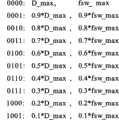
图2为本发明实施例开关控制信号的开关导通时间信息和开关频率信息的关系图;如图2所示:左边一列为开关控制信号的开关导通时间信息,右边一列为开关控制信号的开关频率信息;在本实施例中,图2的每一行代表一个开关控制信号,如“D_max”、“fsw_max”对应开关导通时间信息为D_max,且开关频率信息为fsw_max开关控制信号,以控制功率开关以频率fsw_max,导通时间D_max进行开关动作;如图2所示,所述开关控制信号共有10个。Fig. 2 is the relationship diagram of the switch conduction time information and the switch frequency information of the switch control signal of the embodiment of the present invention; Switching frequency information; in the present embodiment, each row of Fig. 2 represents a switching control signal, such as "D_max", "fsw_max" corresponds to the switch conduction time information as D_max, and the switching frequency information is fsw_max switching control signal, to control The power switch operates with a frequency fsw_max and a conduction time D_max; as shown in FIG. 2 , there are 10 switch control signals.
在本实施例中,所述的基准电压产生单元,具有10个电压输出状态,一个被开关状态选择信号选择的电压输出状态,对应一个输出电压;所述第一比较器将输出电压与所述电流反馈信号进行比较,输出决定开关控制信号的开关导通时间信息的PWM控制信号,即一个输出电压对应一个开关控制信号的开关导通时间信息,所述的10个电压输出状态对应10个开关控制信号的开关导通时间信息。In this embodiment, the reference voltage generation unit has 10 voltage output states, and one voltage output state selected by the switch state selection signal corresponds to one output voltage; the first comparator compares the output voltage with the The current feedback signal is compared, and the PWM control signal that determines the switch conduction time information of the switch control signal is output, that is, one output voltage corresponds to the switch conduction time information of one switch control signal, and the 10 voltage output states correspond to 10 switches. Switch on-time information for the control signal.
在本实施例中,PFM控制单元具有10个频率输出状态,PFM控制单元根据开关状态选择信号选择的频率输出状态,输出具有该频率的PFM控制信号,所述PFM控制信号决定开关控制信号的开关频率信息。In this embodiment, the PFM control unit has 10 frequency output states, and the PFM control unit outputs the PFM control signal with the frequency according to the frequency output state selected by the switch state selection signal, and the PFM control signal determines the switch of the switch control signal frequency information.
图2中的10个开关导通时间信息在“D_max”的基础上,以10%的差距逐次递减至“0.1D_max;图2中的10个开关频率信息在“fsw_max”的基础上以以10%的差距逐次递减至“0.1fsw_max”;其中D_max,fsw_max的大小可根据实际需要进行选择,而且递减的方式也可不局限于等差数列的形式。On the basis of "D_max", the 10 switch conduction time information in Figure 2 are gradually reduced to "0.1D_max" with a gap of 10%; the 10 switching frequency information in Figure 2 are based on "fsw_max" at a rate of 10 The gap of % is gradually reduced to "0.1fsw_max"; where the size of D_max and fsw_max can be selected according to actual needs, and the way of decreasing is not limited to the form of arithmetic sequence.
图3为本发明实施例一种开关状态选择单元的原理框图;如图3所示的开关状态选择单元,包括:Fig. 3 is a functional block diagram of a switch state selection unit according to an embodiment of the present invention; the switch state selection unit shown in Fig. 3 includes:
使能控制单元121,与所述采样单元相连,用以根据所述电压反馈信号产生一使能信号;An enable
编码器122,与所述使能控制单元相连,所述编码器具有多个状态信息,所述多个状态信息分别与上述开关导通时间信息及开关导通频率信息一一对应;所述编码器根据所述使能信号选择输出状态信息;The
译码器123,与所述编码器相连,用以将所述选择输出的状态信息转换为开关状态选择信号。The
图4为本发明实施例开关状态选择单元编码器的状态信息图;所述编码器为可逆计数器,如图4所示:所述多个状态信息为可逆计数器的计数值;所述的计数值为10个四位二进制数;为了与编码器相对应,本实施例中的译码器为4-16译码器。Fig. 4 is the state information diagram of the switch state selection unit encoder of the embodiment of the present invention; The encoder is a reversible counter, as shown in Figure 4: the plurality of state information is the count value of the reversible counter; the count value It is 10 four-bit binary numbers; in order to correspond to the encoder, the decoder in this embodiment is a 4-16 decoder.
图5为本发明实施例状态信息分别与开关控制信号的开关导通时间信息及开关频率信息的对应图;如图5所示:所述多个状态信息分别与所述开关控制信号的开关导通时间信息及开关频率信息一一对应;所述开关导通时间信息的的导通时间从大到小与所述计数值从小到大一一对应;所述开关频率信息的频率从大到小与所述计数值从小到大一一对应;如可逆计数器的最小计数值“0000”对应的开关导通时间信息为“D_max”,最小计数值“0000”对应的开关频率信息为“fsw_max”;如可逆计数器的最大计数值“1001”对应的开关导通时间信息为“0.1D_max”,最大计数值“1001”对应的开关频率信息为“0.1fsw_max”;该对应方式仅为本发明的优选实施方式,在某些情况下也可以使用其他对应方式。所述使能信号包括计数使能信号以及清零使能信号;计数使能信号用以控制所述可逆计数器进行递增方向或递减方向计数并将计数值输出;清零使能信号用以在所述电压反馈信号小于第一基准电压时,控制可逆计数器跳转至最小计数值并输出。Fig. 5 is the corresponding diagram of the state information of the embodiment of the present invention and the switch conduction time information and the switch frequency information of the switch control signal respectively; One-to-one correspondence between the on-time information and the switching frequency information; the one-to-one correspondence between the on-time of the switch on-time information and the count value from small to large; the frequency of the switching frequency information is from large to small One-to-one correspondence with the count value from small to large; for example, the switch conduction time information corresponding to the minimum count value "0000" of the reversible counter is "D_max", and the switching frequency information corresponding to the minimum count value "0000" is "fsw_max"; For example, the switch conduction time information corresponding to the maximum count value "1001" of the reversible counter is "0.1D_max", and the switching frequency information corresponding to the maximum count value "1001" is "0.1fsw_max"; this corresponding method is only a preferred implementation of the present invention method, and in some cases other corresponding methods can also be used. The enabling signal includes a counting enabling signal and a clearing enabling signal; the counting enabling signal is used to control the reversible counter to count in an increasing direction or a decreasing direction and output the count value; the clearing enabling signal is used to When the voltage feedback signal is lower than the first reference voltage, the up-down counter is controlled to jump to the minimum count value and output.
图6为本发明实施例第二种开关状态选择单元的原理框图;如图6所示:所述开关状态选择单元还包括溢出保护单元,用以在所述可逆计数器出现溢出时,控制可逆计数器保持最大或最小计数值并输出,直至所述可逆计数器根据计数使能信号的控制改变计数方向;所述开关状态选择单元还包括编码保持单元,用以将每个控制编码器的状态保持若干个开关周期,直至所保持的若干个开关周期结束或者所述可逆计数器改变计数方向,即所述使能信号翻转。Fig. 6 is a functional block diagram of the second switch state selection unit of the embodiment of the present invention; as shown in Fig. 6: the switch state selection unit also includes an overflow protection unit, which is used to control the reversible counter when the reversible counter overflows Keep the maximum or minimum count value and output it until the reversible counter changes the counting direction according to the control of the count enable signal; the switch state selection unit also includes an encoding holding unit to keep the state of each control encoder switching cycle, until the number of maintained switching cycles ends or the up-down counter changes the counting direction, that is, the enabling signal is reversed.
图7为本发明实施例第三种开关状态选择单元的原理框图;如图7所示:所述使能控制单元包括第二比较器C2、第三比较器C3;所述第二比较器的正输入端与第一基准电压Vref1相连,所述第二比较器的负输入端与所述电压反馈信号VFB相连,所述第二比较器的输出端输出清零使能信号,所述第二比较器的输出端与所述编码器相连;所述第三比较器的负输入端与第二基准电压Vref2相连,所述第三比较器的正输入端与所述电压反馈信号相连,所述第三比较器的输出端输出计数使能信号,所述第三比较器的输出端与所述编码器相连;当第二比较器输出高电平时,此时编码器会清0,输出最小计数值;当第三比较器输出高电平时,编码器进行“+1”计数,当第三比较器输出低电平时,编码器进行“-1”计数。Fig. 7 is a functional block diagram of the third switch state selection unit according to the embodiment of the present invention; as shown in Fig. 7 : the enabling control unit includes a second comparator C2 and a third comparator C3; The positive input terminal is connected to the first reference voltage Vref1, the negative input terminal of the second comparator is connected to the voltage feedback signal VFB, the output terminal of the second comparator outputs a reset enable signal, and the second comparator The output terminal of the comparator is connected with the encoder; the negative input terminal of the third comparator is connected with the second reference voltage Vref2, the positive input terminal of the third comparator is connected with the voltage feedback signal, and the The output end of the third comparator outputs a count enable signal, and the output end of the third comparator is connected to the encoder; when the second comparator outputs a high level, the encoder will be cleared to 0 and output the minimum count value; when the third comparator outputs high level, the encoder counts "+1", when the third comparator outputs low level, the encoder counts "-1".
图8为本发明实施例PWM控制单元、基准电压产生单元、第一比较器以及逻辑单元相结合的原理图;如图8所示,基准电压产生单元具有多个电压输出状态,所述的多个电压输出状态与开关控制信号的开关导通时间信息代表的开关导通时间一一对应且成正比,所述基准电压电路根据开关状态选择信号选择的电压输出状态,输出特定的基准电压;以及第一比较器C1,所述第一比较器的正输入端与所述电流反馈信号相连,所述第一比较器的负输入端与基准电压产生单元的输出端相连,第一比较器的输出端输出PWM控制信号;在本实施例中,所述基准电压产生单元所具有的电压输出状态为10个,所述的10个电压输出状态的电压从大到小与所述可逆计数器的10个四位二进制数从小到大一一对应,即可根据开关状态选择信号输出10种不同的电压,本实施例中所述的基准电压产生单元包括10个分压电阻和10路电压输出开关,并且与一系统电压相连;该10路电压输出开关由经4-16译码器将四位二进制数转换成的开关状态选择信号,从而根据可逆计数器的10个四位二进制数分别输出10个不同基准电压;当所述可逆计数器输出某一计数值时,译码器将该计数值译码为10路开关选择信号,分别控制所述10路输出开关的导通及关断,从而得到一个特定的基准电压,第一比较器将该基准电压与电流反馈信号进行比较,并将比较结果输出;因此第一比较器会根据可逆计数器计数值的不断跳变而输出不同的比较结果,从而产生PWM控制信号,以决定开关控制信号的开关导通时间信息。8 is a schematic diagram of a combination of a PWM control unit, a reference voltage generating unit, a first comparator, and a logic unit according to an embodiment of the present invention; as shown in FIG. 8 , the reference voltage generating unit has multiple voltage output states, and the multiple Each voltage output state corresponds to and is proportional to the switch conduction time represented by the switch conduction time information of the switch control signal, and the reference voltage circuit outputs a specific reference voltage according to the voltage output state selected by the switch state selection signal; and The first comparator C1, the positive input terminal of the first comparator is connected with the current feedback signal, the negative input terminal of the first comparator is connected with the output terminal of the reference voltage generation unit, and the output of the first comparator Terminal output PWM control signal; In the present embodiment, the voltage output state that described reference voltage generation unit has is 10, and the voltage of described 10 voltage output states is from big to small with the 10 of described up-down counter The four-digit binary numbers correspond one-to-one from small to large, and can
如图8所示,所述PFM控制单元包括:变频单元,与开关状态选择单元相连,所述变频单元具有多个频率输出状态,所述变频单元根据开关状态选择信号选择的频率输出状态,输出具有特定频率的PFM控制信号;具体地,所述变频单元可采用多路变频器和固定频率的方波振荡器来实现;所述变频器为10路,在本实施例中,频率输出状态为10个,所述的10个频率输出状态的频率大到小与所述可逆计数器的10个四位二进制数从小到大一一对应,即可根据开关状态选择信号输出10种不同的频率控制信号;本实施例中的变频单元包括固定频率的方波振荡器以及10路变频器,当所述可逆计数器输出某一数值时,译码器将该计数值译码为10路开关选择信号,分别对10路变频器进行控制,从而输出一个特定频率的方波;因此变频单元会根据可逆计数器计数值的不断跳变而输出PFM控制信号,以决定开关控制信号的开关频率信息。As shown in Figure 8, the PFM control unit includes: a frequency conversion unit connected to the switch state selection unit, the frequency conversion unit has a plurality of frequency output states, the frequency output state selected by the frequency conversion unit according to the switch state selection signal, output A PFM control signal with a specific frequency; specifically, the frequency conversion unit can be realized by using a multi-channel frequency converter and a fixed-frequency square wave oscillator; the frequency converter has 10 channels, and in this embodiment, the frequency output state is 10, the frequency of the 10 frequency output states from large to small corresponds to the 10 four-bit binary numbers of the reversible counter from small to large, and 10 different frequency control signals can be output according to the switch state selection signal ; The frequency conversion unit in this embodiment includes a fixed-frequency square wave oscillator and 10 frequency converters. When the reversible counter outputs a certain value, the decoder decodes the count value into 10 switch selection signals, respectively Control the 10-channel frequency converter to output a square wave of a specific frequency; therefore, the frequency conversion unit will output the PFM control signal according to the continuous jump of the count value of the reversible counter to determine the switching frequency information of the switch control signal.
如图8所示,所述的逻辑单元包括:RS触发器,所述RS触发器的R端与所述第一比较器的输出端连接,所述RS触发器的S端与所述PFM控制单元的输出端连接,所述RS触发器的Q端输出开关控制信号。As shown in Figure 8, the logic unit includes: an RS flip-flop, the R end of the RS flip-flop is connected to the output end of the first comparator, the S end of the RS flip-flop is connected to the PFM control The output terminal of the unit is connected, and the Q terminal of the RS flip-flop outputs a switch control signal.
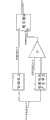
图9为发明实施例开关电源的电路图,所述开关单元电路包含本发明实施例提供的开关电源控制电路,以及一开关电源主电路,在本实施例中所采用的开关电源主电路为隔离型功率变换电路,在某些实施例中也可以采用功率变换非隔离型电路;所述的隔离型功率变换电路,包括:变压器Lp,功率开关Q1,二极管D7,电容C4,电阻R5,所述变压器Lp包括初级线圈A和次级线圈B;所述开关电源控制电路的第一采样电路包括:辅助线圈C,电阻R6,电阻R7,采样保持单元;所述电压反馈信号VFB为由辅助线圈感应并经电阻R6和电阻R7分压再经采样保持单元整形后获得的连续的电压信号,电压反馈信号VFB反映开关电源主电路输出电压的变化;此处的第一采样电路也可以采用光耦直接将开关电源主电路的输出电压反馈至开关电源控制电路等方式实现;所述的第二采样电路为电阻R8。Figure 9 is a circuit diagram of a switching power supply according to an embodiment of the invention. The switching unit circuit includes a switching power supply control circuit provided by an embodiment of the present invention, and a switching power supply main circuit. The switching power supply main circuit used in this embodiment is an isolated type The power conversion circuit may also adopt a power conversion non-isolated circuit in some embodiments; the isolated power conversion circuit includes: a transformer Lp, a power switch Q1, a diode D7, a capacitor C4, a resistor R5, and the transformer Lp includes a primary coil A and a secondary coil B; the first sampling circuit of the switching power supply control circuit includes: an auxiliary coil C, a resistor R6, a resistor R7, and a sampling and holding unit; the voltage feedback signal VFB is induced by the auxiliary coil and The continuous voltage signal obtained after divided by resistor R6 and resistor R7 and then shaped by the sample and hold unit, the voltage feedback signal VFB reflects the change of the output voltage of the main circuit of the switching power supply; the first sampling circuit here can also use an optocoupler to directly The output voltage of the main circuit of the switching power supply is fed back to the control circuit of the switching power supply, etc.; the second sampling circuit is a resistor R8.
下面结合图1至图9对本发明实施例的工作过程作详细说明:Below in conjunction with Fig. 1 to Fig. 9, the working process of the embodiment of the present invention is described in detail:
稳压过程:Stabilization process:
开关电源进入稳压模式后,比较器C2将反映开关电源主电路输出电压变化电压反馈信号VFB与第一基准电压Vref1进行比较,比较器C3将所述电压反馈信号VFB与第二基准电压Vref2进行比较,其中Vref1小于Vref2。After the switching power supply enters the voltage stabilization mode, the comparator C2 compares the voltage feedback signal VFB reflecting the output voltage change of the main circuit of the switching power supply with the first reference voltage Vref1, and the comparator C3 compares the voltage feedback signal VFB with the second reference voltage Vref2 Compare, where Vref1 is less than Vref2.
当VFB大于Vref2时,说明输出电压Vout较高,比较器C2输出计数使能信号给编码器,此时的计数使能信号为高电平,由此控制编码器进行在上一计数值的基础上加1计数,再由译码器转换为开关状态选择信号分别输出给变频单元和基准电压产生单元;此时加1后的计数值对应变频单元减小的频率输出状态,变频单元输出频率减小的PFM控制信号至RS触发器的S端,导致开关控制信号的开关频率信息减小;同时加1后的计数值对应基准电压产生单元减小的电压输出状态,基准电压产生单元输出减小的电压给第一比较器的负输入端,第一比较器将其正输入端接入的电流反馈信号IFB与减小的基准电压进行比较,并输出PWM控制信号给RS触发器的R端,导致开关控制信号的开关导通时间信息减小;由此得到减小的开关导通时间信息及开关频率减小的开关控制信号,使得开关管的导通时间和开关频率均减小,以降低开关电源主电路的输出电压。When VFB is greater than Vref2, it means that the output voltage Vout is relatively high, and the comparator C2 outputs a counting enable signal to the encoder. At this time, the counting enable signal is at a high level, thereby controlling the encoder to perform counting on the basis of the previous count value. Add 1 to count, and then convert it into a switch state selection signal by the decoder and output it to the frequency conversion unit and the reference voltage generation unit respectively; at this time, the count value after adding 1 corresponds to the frequency output state of the frequency conversion unit, and the output frequency of the frequency conversion unit decreases. A small PFM control signal is sent to the S terminal of the RS flip-flop, resulting in a decrease in the switching frequency information of the switch control signal; at the same time, the count value after adding 1 corresponds to the reduced voltage output state of the reference voltage generation unit, and the output of the reference voltage generation unit decreases The voltage is given to the negative input terminal of the first comparator, and the first comparator compares the current feedback signal IFB connected to its positive input terminal with the reduced reference voltage, and outputs a PWM control signal to the R terminal of the RS flip-flop, The switch conduction time information of the switch control signal is reduced; thereby the reduced switch conduction time information and the switch control signal with reduced switching frequency are obtained, so that the conduction time and switching frequency of the switch tube are both reduced to reduce The output voltage of the switching power supply main circuit.
当VFB小于Vref2时,说明输出电压较低,比较器C2输出计数使能信号给编码器,此时的计数使能信号为低电平,由此控制编码器进行在上一计数值的基础上减1计数,再由译码器转换为开关状态选择信号分别输出给变频单元和基准电压产生单元;此时减1后的计数值对应变频单元增加的频率输出状态,变频单元输出频率增加的PFM控制信号至RS触发器的S端,导致开关控制信号的开关频率信息增大;同时减1后的计数值对应基准电压产生单元增加的电压输出状态,基准电压产生单元输出增加的电压给第一比较器的负输入端,第一比较器将其正输入端接入的电流反馈信号IFB与增加的基准电压进行比较,并输出PWM控制信号给RS触发器的R端,导致开关控制信号的开关导通时间信息增加;由此得到增加的开关导通时间信息及开关频率增加的开关控制信号,使得开关管的导通时间和开关频率均增加,以提高开关电源主电路的输出电压。When VFB is less than Vref2, it means that the output voltage is low, and the comparator C2 outputs a count enable signal to the encoder. At this time, the count enable signal is at low level, thereby controlling the encoder to perform counting on the basis of the previous count value. Subtract 1 count, and then convert it into a switch state selection signal by the decoder and output it to the frequency conversion unit and the reference voltage generation unit respectively; at this time, the count value after subtracting 1 corresponds to the increased frequency output state of the frequency conversion unit, and the frequency conversion unit outputs PFM with increased frequency The control signal is sent to the S terminal of the RS flip-flop, causing the switching frequency information of the switch control signal to increase; at the same time, the count value after subtracting 1 corresponds to the increased voltage output state of the reference voltage generating unit, and the reference voltage generating unit outputs the increased voltage to the first The negative input terminal of the comparator, the first comparator compares the current feedback signal IFB connected to its positive input terminal with the increased reference voltage, and outputs the PWM control signal to the R terminal of the RS flip-flop, resulting in the switching of the switch control signal The conduction time information is increased; thus, the increased switch conduction time information and the switch control signal of the increased switching frequency are obtained, so that the conduction time of the switch tube and the switching frequency are both increased, so as to increase the output voltage of the main circuit of the switching power supply.
当VFB小于Vref1时,说明适配器出现输出瞬间过载或者瞬间短路等情况,比较器C2输出清零使能信号给编码器,此时的清零使能信号为高电平,用以控制编码器输出最小计数值,以选择最大的导通占空比和最高的开关频率来驱动功率开关管Q1,可以有效地减少适配器输出的下冲电压。When VFB is less than Vref1, it means that the adapter has instantaneous output overload or short circuit, etc. Comparator C2 outputs a clear enable signal to the encoder. At this time, the clear enable signal is high to control the output of the encoder. The minimum count value is used to select the maximum conduction duty cycle and the highest switching frequency to drive the power switch tube Q1, which can effectively reduce the undershoot voltage output by the adapter.
溢出保护:Overflow protection:
如果计数使能信号一直处于高电平,那么编码器会不断进行加1计数,为避免出现溢出的情况,溢出保护单元用以当编码器出现溢出时,控制编码器保持最大或最小计数值并输出,直至所述可逆计数器改变计数方向。If the counting enable signal is always at a high level, the encoder will continue to count up by 1. In order to avoid overflow, the overflow protection unit is used to control the encoder to maintain the maximum or minimum count value and keep the maximum or minimum count value when the encoder overflows. output until the up-down counter changes count direction.
编码保持:所述开关状态选择单元还包括编码保持单元,用以将每个控制编码器的状态保持若干个开关周期,直至所保持的若干个开关周期结束或者所述可逆计数器改变计数方向,即所述使能信号翻转;以提高整个电路的稳定性。Code hold: the switch state selection unit also includes a code hold unit, which is used to hold the state of each control encoder for several switch cycles, until the held several switch cycles end or the reversible counter changes the counting direction, that is The enable signal is reversed; to improve the stability of the whole circuit.
以上所述仅为本发明的较佳实施例而已,并不用以限制本发明,凡在本发明的精神和原则之内所作的任何修改、等同替换和改进等,均应包含在本发明的保护范围之内。The above descriptions are only preferred embodiments of the present invention, and are not intended to limit the present invention. Any modifications, equivalent replacements and improvements made within the spirit and principles of the present invention should be included in the protection of the present invention. within range.
Claims (12)
Priority Applications (4)
| Application Number | Priority Date | Filing Date | Title |
|---|---|---|---|
| CN201010218923.6ACN102315787B (en) | 2010-06-29 | 2010-06-29 | Switch power supply control circuit and switch power supply |
| EP11800152.8AEP2564495A4 (en) | 2010-06-29 | 2011-06-24 | Switching power supply control circuit, method thereof and switching power supply |
| PCT/CN2011/076336WO2012000407A1 (en) | 2010-06-29 | 2011-06-24 | Switching power supply control circuit, method thereof and switching power supply |
| US13/169,835US8742737B2 (en) | 2010-06-29 | 2011-06-27 | Switched-mode power supply controlling circuit and switched-mode power supply using the same |
Applications Claiming Priority (1)
| Application Number | Priority Date | Filing Date | Title |
|---|---|---|---|
| CN201010218923.6ACN102315787B (en) | 2010-06-29 | 2010-06-29 | Switch power supply control circuit and switch power supply |
Publications (2)
| Publication Number | Publication Date |
|---|---|
| CN102315787Atrue CN102315787A (en) | 2012-01-11 |
| CN102315787B CN102315787B (en) | 2014-03-12 |
Family
ID=45352428
Family Applications (1)
| Application Number | Title | Priority Date | Filing Date |
|---|---|---|---|
| CN201010218923.6AActiveCN102315787B (en) | 2010-06-29 | 2010-06-29 | Switch power supply control circuit and switch power supply |
Country Status (4)
| Country | Link |
|---|---|
| US (1) | US8742737B2 (en) |
| EP (1) | EP2564495A4 (en) |
| CN (1) | CN102315787B (en) |
| WO (1) | WO2012000407A1 (en) |
Cited By (5)
| Publication number | Priority date | Publication date | Assignee | Title |
|---|---|---|---|---|
| CN103312163A (en)* | 2012-03-13 | 2013-09-18 | 上海华虹集成电路有限责任公司 | PFM (Pulse Frequency Modulation) switching circuit of switch power supply |
| CN104038082A (en)* | 2013-03-04 | 2014-09-10 | 比亚迪股份有限公司 | Switch power supply, control method of switch power supply, and control chip |
| CN105048782A (en)* | 2015-08-09 | 2015-11-11 | 安徽普为智能科技有限责任公司 | Control circuit of high-power switching power supply |
| CN105790550A (en)* | 2014-12-23 | 2016-07-20 | 上海岭芯微电子有限公司 | Multi-segment self-adaptive pulse frequency modulation (PFM) controller |
| CN107924161A (en)* | 2015-09-11 | 2018-04-17 | 德克萨斯仪器股份有限公司 | The ultra low power comparator of controlling of sampling ring with adjustment frequency and/or sampled aperture window |
Families Citing this family (4)
| Publication number | Priority date | Publication date | Assignee | Title |
|---|---|---|---|---|
| US12093036B2 (en) | 2011-01-21 | 2024-09-17 | Teladoc Health, Inc. | Telerobotic system with a dual application screen presentation |
| CN102647073B (en)* | 2012-05-15 | 2014-11-26 | 成都芯源系统有限公司 | Switch voltage stabilizing circuit and control circuit and method thereof |
| CN104734510B (en)* | 2013-12-20 | 2017-05-03 | 比亚迪股份有限公司 | Switch power supply and control chip thereof |
| JP6783776B2 (en)* | 2015-01-12 | 2020-11-11 | ツァォ ホア | Switching regulator and its control method |
Citations (6)
| Publication number | Priority date | Publication date | Assignee | Title |
|---|---|---|---|---|
| EP0685923A1 (en)* | 1994-06-03 | 1995-12-06 | Inventio Ag | Low noise operation of a pulsed inverter fed motor |
| CN1707929A (en)* | 2004-06-08 | 2005-12-14 | 尼克森微电子股份有限公司 | A Converter with Automatic Switching of Pulse Width/Frequency Modulation Mode |
| US20090059632A1 (en)* | 2007-08-28 | 2009-03-05 | Yong Li | System And Method For Controlling A Current Limit With Primary Side Sensing Using A Hybrid PWM and PFM Control |
| CN101515756A (en)* | 2008-02-18 | 2009-08-26 | 昂宝电子(上海)有限公司 | Multimode method and system for high-efficiency power control |
| CN101542881A (en)* | 2007-01-22 | 2009-09-23 | 株式会社理光 | Voltage rising/falling type switching regulator and reverse current prevention method |
| JP2009278713A (en)* | 2008-05-12 | 2009-11-26 | Ricoh Co Ltd | Switching regulator |
Family Cites Families (9)
| Publication number | Priority date | Publication date | Assignee | Title |
|---|---|---|---|---|
| GB2421594A (en)* | 2004-12-21 | 2006-06-28 | Cambridge Semiconductor Ltd | Switch mode power supply digital control system |
| EP1900087A2 (en)* | 2005-07-06 | 2008-03-19 | Cambridge Semiconductor Limited | Switch mode power supply control systems |
| GB2433654A (en)* | 2005-12-22 | 2007-06-27 | Cambridge Semiconductor Ltd | Switch mode power supply controller |
| GB0615029D0 (en)* | 2005-12-22 | 2006-09-06 | Cambridge Semiconductor Ltd | Switch mode power supply controllers |
| JP2009213228A (en)* | 2008-03-03 | 2009-09-17 | Nec Electronics Corp | Dc converter |
| CN101667019B (en)* | 2009-07-01 | 2012-10-03 | 成都诺奇尔微电子技术有限公司 | Control method and circuit of double-module modulation and mode smooth conversion switching power supply |
| US8274270B2 (en)* | 2009-07-16 | 2012-09-25 | Feeling Technology Corp. | Adaptive pulse width control power conversation method and device thereof |
| TWI410033B (en)* | 2010-04-06 | 2013-09-21 | Anpec Electronics Corp | Current mode buck converter with fixed pwm/pfm boundary |
| CN102769383B (en)* | 2011-05-05 | 2015-02-04 | 广州昂宝电子有限公司 | System and method for constant-current control via primary side sensing and regulating |
- 2010
- 2010-06-29CNCN201010218923.6Apatent/CN102315787B/enactiveActive
- 2011
- 2011-06-24EPEP11800152.8Apatent/EP2564495A4/ennot_activeWithdrawn
- 2011-06-24WOPCT/CN2011/076336patent/WO2012000407A1/enactiveApplication Filing
- 2011-06-27USUS13/169,835patent/US8742737B2/enactiveActive
Patent Citations (6)
| Publication number | Priority date | Publication date | Assignee | Title |
|---|---|---|---|---|
| EP0685923A1 (en)* | 1994-06-03 | 1995-12-06 | Inventio Ag | Low noise operation of a pulsed inverter fed motor |
| CN1707929A (en)* | 2004-06-08 | 2005-12-14 | 尼克森微电子股份有限公司 | A Converter with Automatic Switching of Pulse Width/Frequency Modulation Mode |
| CN101542881A (en)* | 2007-01-22 | 2009-09-23 | 株式会社理光 | Voltage rising/falling type switching regulator and reverse current prevention method |
| US20090059632A1 (en)* | 2007-08-28 | 2009-03-05 | Yong Li | System And Method For Controlling A Current Limit With Primary Side Sensing Using A Hybrid PWM and PFM Control |
| CN101515756A (en)* | 2008-02-18 | 2009-08-26 | 昂宝电子(上海)有限公司 | Multimode method and system for high-efficiency power control |
| JP2009278713A (en)* | 2008-05-12 | 2009-11-26 | Ricoh Co Ltd | Switching regulator |
Cited By (10)
| Publication number | Priority date | Publication date | Assignee | Title |
|---|---|---|---|---|
| CN103312163A (en)* | 2012-03-13 | 2013-09-18 | 上海华虹集成电路有限责任公司 | PFM (Pulse Frequency Modulation) switching circuit of switch power supply |
| CN103312163B (en)* | 2012-03-13 | 2016-11-23 | 上海华虹集成电路有限责任公司 | The PFM switching circuit of Switching Power Supply |
| CN104038082A (en)* | 2013-03-04 | 2014-09-10 | 比亚迪股份有限公司 | Switch power supply, control method of switch power supply, and control chip |
| WO2014135060A1 (en)* | 2013-03-04 | 2014-09-12 | Shenzhen Byd Auto R&D Company Limited | Switching power source, method and control chip for controlling the same |
| US9553520B2 (en) | 2013-03-04 | 2017-01-24 | Byd Company Limited | Switching power source, method and control chip for controlling the same |
| CN104038082B (en)* | 2013-03-04 | 2017-12-12 | 比亚迪股份有限公司 | Switching Power Supply, the control method of Switching Power Supply and control chip |
| CN105790550A (en)* | 2014-12-23 | 2016-07-20 | 上海岭芯微电子有限公司 | Multi-segment self-adaptive pulse frequency modulation (PFM) controller |
| CN105048782A (en)* | 2015-08-09 | 2015-11-11 | 安徽普为智能科技有限责任公司 | Control circuit of high-power switching power supply |
| CN107924161A (en)* | 2015-09-11 | 2018-04-17 | 德克萨斯仪器股份有限公司 | The ultra low power comparator of controlling of sampling ring with adjustment frequency and/or sampled aperture window |
| CN107924161B (en)* | 2015-09-11 | 2021-03-05 | 德克萨斯仪器股份有限公司 | Ultra-low power comparator with sampling control loop that adjusts frequency and/or sampling aperture window |
Also Published As
| Publication number | Publication date |
|---|---|
| US20110317458A1 (en) | 2011-12-29 |
| CN102315787B (en) | 2014-03-12 |
| WO2012000407A1 (en) | 2012-01-05 |
| EP2564495A1 (en) | 2013-03-06 |
| EP2564495A4 (en) | 2018-01-10 |
| US8742737B2 (en) | 2014-06-03 |
Similar Documents
| Publication | Publication Date | Title |
|---|---|---|
| CN102315787A (en) | Switch power supply control circuit and switch power supply | |
| US8379413B2 (en) | Circuits and methods for controlling power converters including transformers | |
| US9209702B2 (en) | Flyback converter and method for controlling a flyback converter | |
| CN110380628B (en) | Power conversion control chip and power adapter | |
| CN104600813A (en) | Adaptive input current limitation charger and control method thereof | |
| US20110227506A1 (en) | Controllers, systems and methods for controlling power of light sources | |
| CN101605417A (en) | The LED constant-current drive circuit of band light modulation | |
| CN112134461B (en) | Multi-mode control for multiple output voltage power converters | |
| CN102810984A (en) | A switching power supply circuit | |
| US9831786B2 (en) | Switching power-supply device | |
| CN113517730B (en) | Battery charging and discharging system, circuit and method | |
| CN112994470A (en) | Primary side feedback active clamping flyback converter, controller and control method | |
| US8629670B2 (en) | Switching adapter control method for adaptive mobile power systems | |
| CN105141155B (en) | A kind of control system for improving multi-mode digital primary side anti exciting converter dynamic property | |
| KR100906993B1 (en) | Power Control System and Power Control Method of Fuel Cell Hybrid Power Generation System | |
| CN113765395A (en) | A control system and control method for improving the sampling accuracy of primary side feedback of an active clamp flyback converter | |
| WO2020135217A1 (en) | Flyback converter and output voltage acquisition method therefor and apparatus thereof | |
| CN105915060B (en) | Forward conversion circuit with vice-side winding magnetic reset function and its repositioning method | |
| CN201805361U (en) | Switching power supply control circuit and switching power supply | |
| CN109936294B (en) | Control circuit and flyback converter using same | |
| CN217282265U (en) | Lithium battery pack equalizing charging circuit | |
| CN115459565B (en) | State switching control device | |
| CN103595252B (en) | A kind of power supply feedback device | |
| CN111934550B (en) | Anti-backflow circuit, control method thereof and photovoltaic charging controller | |
| CN209593282U (en) | Voltage conversion circuit and LED control circuit using it |
Legal Events
| Date | Code | Title | Description |
|---|---|---|---|
| C06 | Publication | ||
| PB01 | Publication | ||
| C10 | Entry into substantive examination | ||
| SE01 | Entry into force of request for substantive examination | ||
| GR01 | Patent grant | ||
| GR01 | Patent grant | ||
| TR01 | Transfer of patent right | Effective date of registration:20200107 Address after:518119 1 Yanan Road, Kwai Chung street, Dapeng New District, Shenzhen, Guangdong Patentee after:SHENZHEN BYD MICROELECTRONICS Co.,Ltd. Address before:BYD 518118 Shenzhen Road, Guangdong province Pingshan New District No. 3009 Patentee before:BYD Co.,Ltd. | |
| TR01 | Transfer of patent right | ||
| CP01 | Change in the name or title of a patent holder | Address after:518119 No.1 Yan'an Road, Kuiyong street, Dapeng New District, Shenzhen City, Guangdong Province Patentee after:BYD Semiconductor Co.,Ltd. Address before:518119 No.1 Yan'an Road, Kuiyong street, Dapeng New District, Shenzhen City, Guangdong Province Patentee before:SHENZHEN BYD MICROELECTRONICS Co.,Ltd. Address after:518119 No.1 Yan'an Road, Kuiyong street, Dapeng New District, Shenzhen City, Guangdong Province Patentee after:BYD Semiconductor Co.,Ltd. Address before:518119 No.1 Yan'an Road, Kuiyong street, Dapeng New District, Shenzhen City, Guangdong Province Patentee before:BYD Semiconductor Co.,Ltd. | |
| CP01 | Change in the name or title of a patent holder |