CN102315747A - Horizontal linear vibrator - Google Patents
Horizontal linear vibratorDownload PDFInfo
- Publication number
- CN102315747A CN102315747ACN2010106009139ACN201010600913ACN102315747ACN 102315747 ACN102315747 ACN 102315747ACN 2010106009139 ACN2010106009139 ACN 2010106009139ACN 201010600913 ACN201010600913 ACN 201010600913ACN 102315747 ACN102315747 ACN 102315747A
- Authority
- CN
- China
- Prior art keywords
- printed circuit
- circuit board
- coil
- bracket
- pcb
- Prior art date
- Legal status (The legal status is an assumption and is not a legal conclusion. Google has not performed a legal analysis and makes no representation as to the accuracy of the status listed.)
- Granted
Links
- 238000004804windingMethods0.000claims8
- 230000004308accommodationEffects0.000description6
- 238000005476solderingMethods0.000description6
- 238000003780insertionMethods0.000description5
- 230000037431insertionEffects0.000description5
- 230000003993interactionEffects0.000description4
- 230000000694effectsEffects0.000description3
- 238000006073displacement reactionMethods0.000description2
- 230000005684electric fieldEffects0.000description2
- 239000000463materialSubstances0.000description2
- 238000000034methodMethods0.000description2
- 230000009467reductionEffects0.000description2
- 238000003466weldingMethods0.000description2
- 238000004891communicationMethods0.000description1
- 230000007547defectEffects0.000description1
- 238000010892electric sparkMethods0.000description1
- 230000004907fluxEffects0.000description1
- 230000005484gravityEffects0.000description1
- 230000006872improvementEffects0.000description1
- 238000012986modificationMethods0.000description1
- 230000004048modificationEffects0.000description1
- 230000008569processEffects0.000description1
- 230000004043responsivenessEffects0.000description1
- 238000012546transferMethods0.000description1
- WFKWXMTUELFFGS-UHFFFAOYSA-NtungstenChemical compound[W]WFKWXMTUELFFGS-UHFFFAOYSA-N0.000description1
- 229910052721tungstenInorganic materials0.000description1
- 239000010937tungstenSubstances0.000description1
Images


Classifications
- H—ELECTRICITY
- H02—GENERATION; CONVERSION OR DISTRIBUTION OF ELECTRIC POWER
- H02K—DYNAMO-ELECTRIC MACHINES
- H02K33/00—Motors with reciprocating, oscillating or vibrating magnet, armature or coil system
- H02K33/16—Motors with reciprocating, oscillating or vibrating magnet, armature or coil system with polarised armatures moving in alternate directions by reversal or energisation of a single coil system
Landscapes
- Engineering & Computer Science (AREA)
- Power Engineering (AREA)
- Apparatuses For Generation Of Mechanical Vibrations (AREA)
- Reciprocating, Oscillating Or Vibrating Motors (AREA)
Abstract
Translated fromChineseDescription
Translated fromChinese本申请要求于2010年6月29日提交到韩国知识产权局的第10-2010-0062290号韩国专利申请的优先权,该申请公开的内容通过引用被包含于此。This application claims priority from Korean Patent Application No. 10-2010-0062290 filed with the Korean Intellectual Property Office on Jun. 29, 2010, the disclosure of which is hereby incorporated by reference.
技术领域technical field
本发明涉及一种水平线性振动器,更具体地讲,涉及一种被设计成安装在个人移动终端上用于振动的水平线性振动器。The present invention relates to a horizontal linear vibrator, and more particularly, to a horizontal linear vibrator designed to be mounted on a personal mobile terminal for vibration.
背景技术Background technique
一般而言,通信装置必备的关键功能之一是呼叫接收功能。通常使用的呼叫接收功能包括产生旋律或铃声的发声功能以及将振动传递到装置的振动功能。In general, one of the key functions necessary for a communication device is a call receiving function. Commonly used call receiving functions include a sounding function generating a melody or a ringtone and a vibrating function transmitting vibrations to a device.
在这些功能中,通常使用振动功能,以通过防止旋律或铃声经扬声器被传递到外部而避免干扰他人。Among these functions, a vibration function is generally used to avoid disturbing others by preventing melodies or ringtones from being transmitted to the outside through a speaker.
一般而言,为了实现这样的振动功能,小振动电机被驱动,以将驱动力传递到装置的壳体而使装置振动。Generally, in order to realize such a vibration function, a small vibration motor is driven to transmit a driving force to a housing of the device to vibrate the device.
具体地讲,近来,随着移动终端尺寸的减小和质量的提高,触摸屏类型的显示装置的使用受到广泛欢迎,由于当将触摸施加到触摸屏时,需要振动产生功能,因此振动电机已逐渐得到改进。In particular, recently, the use of a touch screen type display device has become popular along with the reduction in size and improvement in quality of mobile terminals, and since a vibration generating function is required when a touch is applied to the touch screen, vibration motors have been gradually obtained. Improve.
应用于现有的移动电话的振动电机产生旋转动力,以使不平衡质量块的旋转部分旋转,因此获得机械振动,在这种情况下,主要取决于通过电刷和换向器(或整流器)的接触点的整流作用而向转子线圈提供电流的结构来产生旋转动力。Vibration motors applied to existing mobile phones generate rotational power to rotate the rotating part of the unbalanced mass, thus obtaining mechanical vibrations, in this case mainly by brushes and commutators (or rectifiers) The rectification effect of the contact point provides the current structure to the rotor coil to generate the rotating power.
然而,在使用换向器的电刷类型的结构中,当电机旋转时,电刷穿过换向器片之间的间隙,产生机械摩擦和电火花并使电刷和换向器磨损,因此缩短了电机的使用寿命。However, in the structure of the brush type using the commutator, when the motor rotates, the brush passes through the gap between the commutator segments, causing mechanical friction and electric sparks, and wears the brush and the commutator, so shorten the life of the motor.
另外,因为通过使用惯性力矩将电压施加到电机,所以要花时间才能达到目标振动量,因此难以实现适合于使用触摸屏的个人移动终端等的振动。In addition, because the voltage is applied to the motor by using the moment of inertia, it takes time to reach the target vibration amount, so it is difficult to achieve vibration suitable for personal mobile terminals using a touch screen, etc.
为了克服使用寿命和响应度方面的这些缺点,排除了旋转原理的线性振动器正被使用。In order to overcome these disadvantages in terms of service life and responsiveness, linear vibrators excluding the principle of rotation are being used.
线性振动器通过具有谐振频率的电磁力来产生振动,所述谐振频率通过利用安装在线性振动器中的弹簧和与该弹簧结合的质量体来确定。The linear vibrator generates vibration by electromagnetic force having a resonance frequency determined by using a spring installed in the linear vibrator and a mass body combined with the spring.
然而,这样的线性振动器被设计成沿竖直方向振动,并且只有当通过确保设置在线性振动器中的质量体的上下位移而使线性振动器运动时才能产生振动。这对线性振动器的厚度造成限制。However, such a linear vibrator is designed to vibrate in a vertical direction, and vibration can be generated only when the linear vibrator is moved by ensuring vertical displacement of a mass body provided in the linear vibrator. This places a limit on the thickness of the linear vibrator.
另外,为了实现大的振动量,应当增加线性振动器的厚度。为此,需要较大的空间来将振动器安装在个人移动终端上,从而不适于小型化。In addition, in order to realize a large vibration amount, the thickness of the linear vibrator should be increased. For this reason, a large space is required to install the vibrator on the personal mobile terminal, so that it is not suitable for miniaturization.
发明内容Contents of the invention
本发明的一方面在于提供一种水平线性振动器,该水平线性振动器沿着个人移动终端的水平方向(即,长度方向)振动、产生大的振动功率并防止印刷电路板和线圈的焊接部分与振动单元接触。An aspect of the present invention is to provide a horizontal linear vibrator that vibrates along the horizontal direction (ie, lengthwise direction) of a personal mobile terminal, generates a large vibration power, and prevents soldering of printed circuit boards and coils. contact with the vibrating unit.
根据本发明的一方面,提供一种水平线性振动器,该水平线性振动器包括:支架,提供内部空间;振动单元,安装在所述内部空间中并包括水平线性地运动的质量体;磁场单元,包括固定到所述质量体的磁体以及安装在所述磁体的磁场内的线圈,所述磁场单元产生电磁力以允许振动单元水平线性地运动,其中,所述线圈包括线圈线,所述线圈线设置在支架和印刷电路板之间并延伸到所述支架的内部空间之外,使得所述线圈线与所述印刷电路板连接,以在所述支架的内部空间之外将电力从外部源施加到线圈上。According to an aspect of the present invention, there is provided a horizontal linear vibrator comprising: a bracket providing an internal space; a vibration unit installed in the internal space and including a mass body moving horizontally and linearly; a magnetic field unit , including a magnet fixed to the mass body and a coil installed in the magnetic field of the magnet, the magnetic field unit generates electromagnetic force to allow the vibration unit to move horizontally and linearly, wherein the coil includes a coil wire, and the coil A wire is disposed between the bracket and the printed circuit board and extends out of the interior space of the bracket such that the coil wire is connected to the printed circuit board to transfer power from an external source outside the interior space of the bracket applied to the coil.
所述线圈线可被设置在支架的上表面和印刷电路板的下表面之间,所述印刷电路板可包括凹进部分,所述凹进部分允许延伸到印刷电路板上部的线圈线固定到所述凹进部分。The coil wire may be disposed between an upper surface of the bracket and a lower surface of a printed circuit board, and the printed circuit board may include a recess allowing the coil wire extending to an upper side of the printed circuit board to be fixed to the the recessed portion.
所述印刷电路板可包括切口部分,所述切口部分允许延伸到印刷电路板上部的线圈线插入到所述切口部分中。The printed circuit board may include a cutout portion allowing a coil wire extending to an upper portion of the printed circuit board to be inserted into the cutout portion.
所述印刷电路板可包括多个印刷电路板,所述线圈线可被插入到所述多个印刷电路板之间,以延伸到所述多个印刷电路板的上部。The printed circuit board may include a plurality of printed circuit boards, and the coil wire may be inserted between the plurality of printed circuit boards to extend to upper portions of the plurality of printed circuit boards.
所述印刷电路板可包括延伸到所述支架的内部空间之外的延伸部分,所述线圈线可被焊接在所述延伸部分上。The printed circuit board may include an extension portion extending out of the inner space of the bracket, and the coil wire may be soldered to the extension portion.
所述磁体可具有矩形形状,以增加电磁力。The magnet may have a rectangular shape to increase electromagnetic force.
所述线圈可具有与所述磁体的形状相对应的形状。The coil may have a shape corresponding to that of the magnet.
所述支架可在其内表面上具有至少一个或多个突起,所述印刷电路板可被所述至少一个或多个突起固定。The bracket may have at least one or more protrusions on an inner surface thereof, and the printed circuit board may be fixed by the at least one or more protrusions.
所述水平线性振动器还可包括覆盖所述支架的上部的盖单元。The horizontal linear vibrator may further include a cover unit covering an upper portion of the bracket.
所述水平线性振动器还可包括阻尼器,所述阻尼器设置在所述支架和所述线圈之间并吸收所述振动单元的振动。The horizontal linear vibrator may further include a damper disposed between the bracket and the coil and absorbing vibration of the vibration unit.
附图说明Description of drawings
通过下面结合附图进行的详细描述,本发明的上述和其他方面、特点和其他优点将会被更加清楚地理解,其中:The above and other aspects, features and other advantages of the present invention will be more clearly understood through the following detailed description in conjunction with the accompanying drawings, wherein:
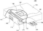
图1是示意性地示出根据本发明的示例性实施例的水平线性振动器的剖开立体图;1 is a cutaway perspective view schematically showing a horizontal linear vibrator according to an exemplary embodiment of the present invention;
图2是示意性地示出根据本发明的示例性实施例的水平线性振动器的分解立体图;2 is an exploded perspective view schematically showing a horizontal linear vibrator according to an exemplary embodiment of the present invention;
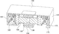
图3是示出根据本发明的示例性实施例的设置在水平线性振动器中的振动组件的示意性立体图;3 is a schematic perspective view illustrating a vibrating assembly disposed in a horizontal linear vibrator according to an exemplary embodiment of the present invention;
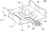
图4是示出根据本发明的示例性实施例的设置在水平线性振动器中的支架组件的示意性立体图;4 is a schematic perspective view illustrating a bracket assembly provided in a horizontal linear vibrator according to an exemplary embodiment of the present invention;
图5是示出根据本发明的另一示例性实施例的设置在水平线性振动器中的支架组件的示意性立体图;5 is a schematic perspective view illustrating a bracket assembly provided in a horizontal linear vibrator according to another exemplary embodiment of the present invention;
图6是示出根据本发明的另一示例性实施例的设置在水平线性振动器中的支架组件的示意性立体图;6 is a schematic perspective view illustrating a bracket assembly provided in a horizontal linear vibrator according to another exemplary embodiment of the present invention;
图7是示出根据本发明的示例性实施例的在水平线性振动器振动时支架的振动的示意性立体图;7 is a schematic perspective view illustrating vibration of a stand when a horizontal linear vibrator vibrates according to an exemplary embodiment of the present invention;
图8是示出根据本发明的示例性实施例的水平线性振动器中的阻尼器和盖单元的效果的示意性立体图。8 is a schematic perspective view showing the effects of a damper and a cover unit in a horizontal linear vibrator according to an exemplary embodiment of the present invention.
具体实施方式Detailed ways
现在将参照附图来详细描述本发明的示例性实施例。然而,本发明可以以多种不同的形式实施,并不应该被解释为限于在此阐述的实施例。相反,提供这些实施例使得本公开将是彻底的和完整的,并将把本发明的范围充分地传达给本领域的技术人员。Exemplary embodiments of the present invention will now be described in detail with reference to the accompanying drawings. However, this invention may be embodied in many different forms and should not be construed as limited to the embodiments set forth herein. Rather, these embodiments are provided so that this disclosure will be thorough and complete, and will fully convey the scope of the invention to those skilled in the art.
在附图中,为了清晰起见,会夸大形状和尺寸,将始终使用相同的标号来指示相同或相似的组件。In the drawings, the shapes and dimensions may be exaggerated for clarity, and the same reference numerals will be used throughout to designate the same or like components.
图1是示意性地示出根据本发明的示例性实施例的水平线性振动器的剖开立体图。图2是示意性地示出根据本发明的示例性实施例的水平线性振动器的分解立体图。图3是示意性地示出根据本发明的示例性实施例的设置在水平线性振动器中的振动组件的立体图。FIG. 1 is a cutaway perspective view schematically showing a horizontal linear vibrator according to an exemplary embodiment of the present invention. FIG. 2 is an exploded perspective view schematically showing a horizontal linear vibrator according to an exemplary embodiment of the present invention. FIG. 3 is a perspective view schematically showing a vibration assembly provided in a horizontal linear vibrator according to an exemplary embodiment of the present invention.
参照图1至图3,根据本发明的示例性实施例的水平线性振动器100可包括支架110、振动单元120、磁场单元130以及盖单元140。Referring to FIGS. 1 to 3 , a horizontal
支架110具有这样的结构,在该结构中,支架110的上部和沿长度方向的侧部缺失,以与盖单元140对应。即,支架110具有支架下板112以及沿宽度方向的支撑板114,且支架110与盖单元140装配以形成内部空间。The
具有矩形形状的线圈132可被固定到支架下板112的上部,印刷电路板150可被安装到靠近线圈132的位置处。A
至少一个或多个突起116可形成在支架下板112的上部上,以与印刷电路板150结合。印刷电路板150可被设置在突起116之间,以被插入并被固定到突起116上。At least one or
这里,线圈132不限于矩形形状,并可被修改成具有本发明所属领域中已知的各种形式。Here, the
支撑板114被形成为被弯曲,以与支架下板112垂直,从而允许弹簧构件160插入并固定到支撑板114的内表面。因此,支架110的外形可呈U形,但是支架110的外形不限于此。The
支撑板114置于振动单元120的两侧部分,以支撑振动单元120,从而允许振动单元120振动。
印刷电路板150可被安装在支架下板112上。印刷电路板150被连接到外部输入端子并将施加于其上的电力传递到线圈132。印刷电路板150可具有形成在印刷电路板150上表面上的图案部分以及形成在印刷电路板150中以允许线圈132穿过的开口部分。A printed
然而,印刷电路板150不限于印刷电路板150与支架110分开地形成的构造。即,根据设计者的意图,印刷电路板150与支架110可一体地形成。However, the printed
这里,线圈132可包括矩形线圈132。当将电力从外部源施加到矩形线圈132时,矩形线圈132用于产生一定强度的电场。矩形线圈132可被固定到支架下板112的上部。Here, the
然而,线圈132可被设置在支架下板112的上表面上。可形成单独的板以使线圈132设置于其上。However, the
另外,线圈132可包括线圈线133,使得线圈线133通过焊接与印刷电路板150的图案部分连接,这样能够将电力从外部源施加到线圈132。In addition, the
线圈线133可延伸到支架110的内部空间之外,下面将对其进行详细的描述。The
阻尼器134可被设置在线圈132的下部和支架下板112的上部之间。阻尼器134可用于防止在振动单元120振动时支架110的外表面晃动。The
另外,阻尼器134可保护水平线性振动器的内部组件免受外部冲击,这样可实现可靠性。In addition, the
振动单元120可包括其中容纳线圈132和磁体136的磁轭部分170以及其中容纳磁轭部分170的质量体180。通过磁体136与线圈132的相互作用,振动单元120可沿水平方向振动。The
质量体180用于将一定质量施加到振动单元120以进行线性振动,质量体180包括容纳空间以在其中容纳磁轭部分170的中央部分。The
因此,质量体180在其容纳空间容纳磁轭部分170的中央部分,而磁轭部分170容纳磁体136。质量体180和磁轭部分170被装配成使得从磁轭部分170弯曲的延伸部分172与质量体180的外侧表面接触。Accordingly, the
质量体180可具有一定大小的质量并根据磁体136与线圈132的相互作用沿振动方向水平地振动。The
这里,振动方向是指与线圈132水平的方向。Here, the vibration direction refers to a direction horizontal to the
质量体180可包括插入部分182,插入部分182形成为与其中容纳磁轭部分170的容纳空间相邻。The
可在形成质量体180的内部容纳空间时形成插入部分182。插入部分可被设置在内部容纳空间的两侧部分。The
插入部分182可形成空间,子质量体184被另外插入到该空间中。子质量体184形成为具有一定的单位质量。根据需要,可将一个或多个子质量体插入到插入部分182中。The
子质量体184可由具有高比重(specific gravity)的钨或具有一定重量的普通材料制成。然而,不限于此,根据设计者的意图,子质量体184可由各种其他材料制成。The
磁场单元130可包括线圈132以及与线圈132相邻设置的磁体136。The
振动单元120的振动方向由洛伦兹力(Lorentz Force)来确定,洛伦兹力取决于线圈132所产生的频率的电场力和磁体136朝着磁轭部分170所产生的磁场的方向。The vibration direction of the
磁体136用于通过产生一定强度的磁场根据磁体136与线圈132的相互作用而迫使振动单元120线性振动。磁体136附着到磁芯138的两侧。The
这里,附着到磁芯138的两侧的磁体136可被设置成使得其相同的磁极彼此面对。Here, the
磁轭部分170用于使磁路(circuit)自闭合(self-close)以平稳地形成磁体136的磁通量。磁轭部分170可具有其中容纳线圈132和磁体136的内部空间。The
磁轭部分170的两侧表面可包括延伸部分172,延伸部分172弯曲以使其被定位成与支架下板112垂直并使其紧密地附着到质量体180的外侧表面。因此,当将磁轭部分170的中央部分容纳在质量体180的容纳空间中时,延伸部分172可紧密地附着到质量体180的外侧表面,从而能够使质量体180和延伸部分172稳定地结合。Both side surfaces of the
弹簧构件160用于弹性地支撑振动单元120,以使其沿直线方向水平地运动。在将弹簧构件160的一侧固定到支架110的沿宽度方向的支撑板114的状态下,弹簧构件160的另一侧被固定到振动单元120,从而弹性地支撑振动单元120。The
这里,弹簧构件160设置在振动单元120两侧的相应位置,优选地,可在振动单元120的每侧布置一对弹簧构件160,并设置在支架110的上部。弹簧构件160可以是(例如)螺旋弹簧或片簧等。Here, the
盖单元140形成为覆盖支架110的上部并保护内部组件免受外部冲击。The
为了将盖单元140与支架110结合,支架110和盖单元140可分别具有突出部分以及其中容纳突出部分的容纳凹口,或者盖单元140和支架110可分别具有突出部分以及其中容纳突出部分的容纳凹口。In order to combine the
图4是示出根据本发明的示例性实施例的设置在水平线性振动器中的支架组件的示意性立体图。图5是示出根据本发明的另一示例性实施例的设置在水平线性振动器中的支架组件的示意性立体图。图6是示出根据本发明的另一示例性实施例的设置在水平线性振动器中的支架组件的示意性立体图。FIG. 4 is a schematic perspective view illustrating a bracket assembly provided in a horizontal linear vibrator according to an exemplary embodiment of the present invention. FIG. 5 is a schematic perspective view illustrating a bracket assembly provided in a horizontal linear vibrator according to another exemplary embodiment of the present invention. FIG. 6 is a schematic perspective view illustrating a bracket assembly provided in a horizontal linear vibrator according to another exemplary embodiment of the present invention.
参照图4,根据本发明的示例性实施例的设置在水平线性振动器100中的支架组件200可包括支架110、印刷电路板150、线圈132以及线圈线133。Referring to FIG. 4 , a
本实施例的支架110和印刷电路板150与上述实施例的支架110和印刷电路板150基本相同,因此将省略对其的详细描述。The
线圈132被设置在支架下板112的上部上。另外,线圈132可包括线圈线133,使得线圈线133通过焊接与印刷电路板150的图案部分连接,这样能够将电力从外部源施加到线圈132。The
线圈线133可被设置在支架下板112和印刷电路板150之间,并可形成为延伸到支架110的内部空间之外。The
印刷电路板150可包括延伸到支架110的内部空间之外的延伸部分154。线圈线133可延伸到延伸部分154。The printed
印刷电路板150可具有位于延伸部分154的侧表面中的凹进部分152,以允许线圈线133穿过该凹进部分152。设置在印刷电路板150的下部的线圈线133可穿过凹进部分152,从而延伸到印刷电路板150的上部。The printed
即,线圈线133被设置在支架下板112的上表面和印刷电路板150的下表面之间,并穿过印刷电路板150的凹进部分152延伸到印刷电路板150的上部。凹进部分152允许延伸到印刷电路板150的上部的线圈线133被固定。That is, the
另外,延伸到印刷电路板150的上部的线圈线133通过焊接在延伸部分154上与印刷电路板150的图案部分连接,这样能够将电力从外部源施加到线圈线133。In addition, the
另外,至少一个或多个突起116设置在支架下板112的上部上,以与印刷电路板150结合,印刷电路板150可被设置在突起116之间,以被插入并被固定到突起116上。In addition, at least one or
参照图5,根据本发明的另一示例性实施例的设置在水平线性振动器100中的支架组件200可包括具有切口部分156的印刷电路板150。Referring to FIG. 5 , a
印刷电路板150可具有形成在其表面上的切口部分156。切口部分156可允许延伸到支架110的内部空间之外的线圈线133插入到切口部分156中。The printed
线圈线133被插入并被固定到切口部分156。线圈线133在切口部分156的边缘处延伸到外部,以通过焊接在印刷电路板150的延伸部分154上与印刷电路板150的图案部分连接,这样能够将电力从外部源施加到线圈线133。The
参照图6,根据本发明的另一示例性实施例的设置在水平线性振动器100中的支架组件200可包括具有多个印刷电路板的印刷电路板150。Referring to FIG. 6 , a
多个印刷电路板150可允许延伸到支架110的内部空间之外的线圈线133插入到所述多个印刷电路板150之间。即,线圈线133可被插入到印刷电路板150之间。The plurality of printed
线圈线133被插入并被固定在印刷电路板150之间。线圈线133在印刷电路板150的延伸部分154之间延伸到外部。线圈线133通过焊接在印刷电路板150的延伸部分154上与印刷电路板150的图案部分连接,这样能够将电力从外部源施加到线圈线133。The
另外,至少一个或多个突起116可形成在支架下板112的上部上,以与印刷电路板150结合。突起116可被插入并被固定到设置在印刷电路板150中的孔中。In addition, at least one or
在支架组件200中,线圈线133延伸到支架110的内部空间之外,线圈线133与印刷电路板150的焊接在支架110的内部空间之外(即,印刷电路板150的延伸部分154)进行,这样可使相对于支架110的内部组件的空间效率最大化。In the
另外,由于防止了振动单元120与线圈132和印刷电路板150的焊接部分接触,因此可避免由接触引起的外物缺陷(foreign object defect)。In addition, since the
另外,可防止在焊接过程中可能会对线圈132造成的损害。In addition, possible damage to the
图7是示出根据本发明的示例性实施例的在水平线性振动器振动时支架的振动的示意性立体图。图8是示出根据本发明的示例性实施例的水平线性振动器中的阻尼器和盖单元的效果的示意性立体图。7 is a schematic perspective view illustrating vibration of a stand when a horizontal linear vibrator vibrates according to an exemplary embodiment of the present invention. 8 is a schematic perspective view showing the effects of a damper and a cover unit in a horizontal linear vibrator according to an exemplary embodiment of the present invention.
如图7中所示,设置质量体180以在其中容纳磁轭部分170,弹簧构件160被插入到质量体180的两侧部分。As shown in FIG. 7 , a
当振动单元120通过磁体136与线圈132的相互作用而振动时,支架110的支撑板114自然晃动(见)。支架110的这样的晃动可导致振动单元120的振动功率的降低。When the
参照图8,在设置质量体180以在其中容纳磁轭部分170并将弹簧构件160插入到质量体180的两侧部分之后,装配盖单元140以覆盖支架110。Referring to FIG. 8 , after disposing the
因此,由于盖单元140的侧壁142与支架110的支撑板114的外侧表面接触,因此防止在质量体180如图7中所示地进行振动时支架110的支撑板114晃动,并因此能够提高振动单元120的振动功率。Therefore, since the
另外,在弹簧构件160通过支架110的支撑板114的晃动而与支撑板114一起运动的情况下,弹簧构件160的运动量变大,并因此可降低弹簧构件160的使用寿命。然而,在本实施例中,防止了支架110的外侧表面晃动,这样可进一步延长弹簧构件160的使用寿命。In addition, in a case where the
这里,阻尼器134以及盖单元140的侧壁142可防止支撑板114晃动。Here, the
如上所述,由于根据本发明的示例性实施例的水平线性振动器沿个人移动终端的水平方向振动而不是沿个人移动终端的厚度方向振动,因此可实现个人移动终端厚度的减小以及振动单元沿个人移动终端的长度方向的运动位移的增加,这样能够提高振动功能。As described above, since the horizontal linear vibrator according to the exemplary embodiment of the present invention vibrates in the horizontal direction of the personal mobile terminal instead of vibrating in the thickness direction of the personal mobile terminal, it is possible to realize the reduction of the thickness of the personal mobile terminal and the vibrating unit The increase in movement displacement along the length direction of the personal mobile terminal can improve the vibration function.
另外,由于线圈和印刷电路板的焊接部分位于支架的外部,因此防止在振动单元振动时焊接部分与振动单元接触。In addition, since the soldered part of the coil and the printed circuit board is located outside the bracket, the soldered part is prevented from being in contact with the vibration unit when the vibration unit vibrates.
尽管已经结合示例性实施例示出和描述了本发明,但是本领域的技术人员应该清楚,在不脱离由权利要求限定的本发明的精神和范围的情况下,可以进行修改和变化。While the invention has been shown and described in conjunction with exemplary embodiments, it will be apparent to those skilled in the art that modifications and changes may be made without departing from the spirit and scope of the invention as defined in the claims.
Claims (10)
Applications Claiming Priority (2)
| Application Number | Priority Date | Filing Date | Title |
|---|---|---|---|
| KR1020100062290AKR101101506B1 (en) | 2010-06-29 | 2010-06-29 | Horizontal vibrator |
| KR10-2010-0062290 | 2010-06-29 |
Publications (2)
| Publication Number | Publication Date |
|---|---|
| CN102315747Atrue CN102315747A (en) | 2012-01-11 |
| CN102315747B CN102315747B (en) | 2014-02-19 |
Family
ID=45351846
Family Applications (1)
| Application Number | Title | Priority Date | Filing Date |
|---|---|---|---|
| CN201010600913.9AExpired - Fee RelatedCN102315747B (en) | 2010-06-29 | 2010-12-17 | Horizontal Linear Vibrator |
Country Status (3)
| Country | Link |
|---|---|
| US (1) | US8288899B2 (en) |
| KR (1) | KR101101506B1 (en) |
| CN (1) | CN102315747B (en) |
Cited By (31)
| Publication number | Priority date | Publication date | Assignee | Title |
|---|---|---|---|---|
| CN105281533A (en)* | 2014-06-03 | 2016-01-27 | 苹果公司 | Linear actuator |
| WO2017120758A1 (en)* | 2016-01-12 | 2017-07-20 | 深圳多哚新技术有限责任公司 | Pcb mounting bracket based on vr glasses and vr glasses |
| US9779592B1 (en) | 2013-09-26 | 2017-10-03 | Apple Inc. | Geared haptic feedback element |
| CN107276359A (en)* | 2017-02-14 | 2017-10-20 | 天津富禄通信技术有限公司 | Horizontal vibration motor |
| US9830782B2 (en) | 2014-09-02 | 2017-11-28 | Apple Inc. | Haptic notifications |
| US9886093B2 (en) | 2013-09-27 | 2018-02-06 | Apple Inc. | Band with haptic actuators |
| US9911553B2 (en) | 2012-09-28 | 2018-03-06 | Apple Inc. | Ultra low travel keyboard |
| US9934661B2 (en) | 2009-09-30 | 2018-04-03 | Apple Inc. | Self adapting haptic device |
| US10013058B2 (en) | 2010-09-21 | 2018-07-03 | Apple Inc. | Touch-based user interface with haptic feedback |
| US10039080B2 (en) | 2016-03-04 | 2018-07-31 | Apple Inc. | Situationally-aware alerts |
| CN108347151A (en)* | 2017-01-24 | 2018-07-31 | 四川安和精密电子电器有限公司 | A kind of linear vibration motor |
| US10120446B2 (en) | 2010-11-19 | 2018-11-06 | Apple Inc. | Haptic input device |
| US10126817B2 (en) | 2013-09-29 | 2018-11-13 | Apple Inc. | Devices and methods for creating haptic effects |
| CN109347299A (en)* | 2012-12-20 | 2019-02-15 | 苹果公司 | Voice coil motor optical image stabilization |
| US10236760B2 (en) | 2013-09-30 | 2019-03-19 | Apple Inc. | Magnetic actuators for haptic response |
| US10268272B2 (en) | 2016-03-31 | 2019-04-23 | Apple Inc. | Dampening mechanical modes of a haptic actuator using a delay |
| US10276001B2 (en) | 2013-12-10 | 2019-04-30 | Apple Inc. | Band attachment mechanism with haptic response |
| US10353467B2 (en) | 2015-03-06 | 2019-07-16 | Apple Inc. | Calibration of haptic devices |
| CN110220587A (en)* | 2018-11-28 | 2019-09-10 | 天津富禄通信技术有限公司 | Quadrangle vertical vibration pick-up |
| US10459521B2 (en) | 2013-10-22 | 2019-10-29 | Apple Inc. | Touch surface for simulating materials |
| US10481691B2 (en) | 2015-04-17 | 2019-11-19 | Apple Inc. | Contracting and elongating materials for providing input and output for an electronic device |
| US10545604B2 (en) | 2014-04-21 | 2020-01-28 | Apple Inc. | Apportionment of forces for multi-touch input devices of electronic devices |
| US10566888B2 (en) | 2015-09-08 | 2020-02-18 | Apple Inc. | Linear actuators for use in electronic devices |
| US10599223B1 (en) | 2018-09-28 | 2020-03-24 | Apple Inc. | Button providing force sensing and/or haptic output |
| US10622538B2 (en) | 2017-07-18 | 2020-04-14 | Apple Inc. | Techniques for providing a haptic output and sensing a haptic input using a piezoelectric body |
| US10691211B2 (en) | 2018-09-28 | 2020-06-23 | Apple Inc. | Button providing force sensing and/or haptic output |
| WO2020140553A1 (en)* | 2018-12-30 | 2020-07-09 | 瑞声声学科技(深圳)有限公司 | Linear vibration electric motor |
| CN114421730A (en)* | 2021-12-31 | 2022-04-29 | 歌尔股份有限公司 | Linear vibration motor |
| US11380470B2 (en) | 2019-09-24 | 2022-07-05 | Apple Inc. | Methods to control force in reluctance actuators based on flux related parameters |
| US11809631B2 (en) | 2021-09-21 | 2023-11-07 | Apple Inc. | Reluctance haptic engine for an electronic device |
| US11977683B2 (en) | 2021-03-12 | 2024-05-07 | Apple Inc. | Modular systems configured to provide localized haptic feedback using inertial actuators |
Families Citing this family (66)
| Publication number | Priority date | Publication date | Assignee | Title |
|---|---|---|---|---|
| KR101796094B1 (en)* | 2010-09-01 | 2017-11-09 | 주식회사 이엠텍 | Horizental vibration motor |
| JP5461381B2 (en)* | 2010-12-17 | 2014-04-02 | アルプス電気株式会社 | Vibration generator |
| KR101255914B1 (en)* | 2010-12-31 | 2013-04-23 | 삼성전기주식회사 | Linear Vibration Motor |
| US20130099600A1 (en)* | 2011-10-24 | 2013-04-25 | Lg Innotek Co., Ltd. | Linear vibrator |
| KR101216494B1 (en)* | 2011-12-27 | 2012-12-31 | (주)지원에프알에스 | Device for generating micro electrical current |
| CN102820760A (en)* | 2012-01-06 | 2012-12-12 | 瑞声声学科技(深圳)有限公司 | Vibration motor, upper cover of vibration motor and production method of upper cover |
| JP5923797B2 (en)* | 2012-03-02 | 2016-05-25 | 日本電産セイミツ株式会社 | Vibration generator |
| JP5943419B2 (en)* | 2012-03-16 | 2016-07-05 | 日本電産セイミツ株式会社 | Vibration generator |
| WO2015020663A1 (en) | 2013-08-08 | 2015-02-12 | Honessa Development Laboratories Llc | Sculpted waveforms with no or reduced unforced response |
| US9928950B2 (en) | 2013-09-27 | 2018-03-27 | Apple Inc. | Polarized magnetic actuators for haptic response |
| CN204030834U (en)* | 2014-07-09 | 2014-12-17 | 瑞声光电科技(常州)有限公司 | Vibrating motor |
| CN204334278U (en)* | 2014-12-23 | 2015-05-13 | 瑞声光电科技(常州)有限公司 | vibration motor |
| CN204559358U (en)* | 2015-04-01 | 2015-08-12 | 常州美欧电子有限公司 | Vibrating motor |
| TWM514168U (en)* | 2015-04-02 | 2015-12-11 | Topray Mems Inc | Linear resonant actuator |
| CN205004934U (en)* | 2015-07-30 | 2016-01-27 | 瑞声光电科技(常州)有限公司 | Vibration motor |
| CN205081655U (en)* | 2015-10-15 | 2016-03-09 | 瑞声光电科技(常州)有限公司 | Double resonance vibrating motor |
| CN205377621U (en)* | 2015-11-03 | 2016-07-06 | 瑞声光电科技(常州)有限公司 | Vibration motor |
| CN205356112U (en)* | 2015-12-30 | 2016-06-29 | 瑞声光电科技(常州)有限公司 | Vibration motor |
| US10468956B2 (en) | 2016-02-05 | 2019-11-05 | Apple Inc. | Electrical component with moving mass and flexible cables |
| CN105811725B (en)* | 2016-03-11 | 2018-09-07 | 歌尔股份有限公司 | A kind of linear vibration motor |
| CN205847041U (en)* | 2016-06-23 | 2016-12-28 | 瑞声科技(新加坡)有限公司 | Vibrating motor |
| CN206313634U (en)* | 2016-12-10 | 2017-07-07 | 瑞声科技(南京)有限公司 | Vibrating motor |
| CN110337778B (en)* | 2017-03-02 | 2022-03-01 | 阿尔卑斯阿尔派株式会社 | Vibration generating device and electronic apparatus |
| CN106849587B (en)* | 2017-03-14 | 2022-04-05 | 歌尔股份有限公司 | Linear vibration motor and electronic device |
| US11509194B2 (en)* | 2017-03-21 | 2022-11-22 | Mitsubishi Electric Corporation | Motor with rotor and endplates with blade parts and cooling hole |
| CN207098907U (en)* | 2017-04-14 | 2018-03-13 | 瑞声科技(新加坡)有限公司 | Resonator device and the electronic equipment with this kind of resonator device |
| CN207074948U (en)* | 2017-04-14 | 2018-03-06 | 瑞声科技(新加坡)有限公司 | Resonator device |
| CN109256928B (en)* | 2017-07-14 | 2021-02-26 | 讯芯电子科技(中山)有限公司 | Linear vibrator |
| GB2572349B (en)* | 2018-03-27 | 2021-08-11 | Perpetuum Ltd | An electromechanical generator for converting mechanical vibrational energy into electrical energy |
| GB2572350B (en)* | 2018-03-27 | 2023-01-25 | Hitachi Rail Ltd | An electromechanical generator for converting mechanical vibrational energy into electrical energy |
| JP7063691B2 (en)* | 2018-04-06 | 2022-05-09 | フォスター電機株式会社 | Vibration actuator |
| CN208955872U (en)* | 2018-08-03 | 2019-06-07 | 瑞声科技(南京)有限公司 | Linear vibration electric motor |
| CN112640275B (en)* | 2018-08-28 | 2024-12-10 | 美蓓亚三美株式会社 | Vibration actuators and electronic devices |
| KR102138339B1 (en)* | 2018-10-24 | 2020-07-27 | 주식회사 엠플러스 | Sound vibration actuator |
| JP7222661B2 (en)* | 2018-10-31 | 2023-02-15 | ミネベアミツミ株式会社 | Vibration actuator and vibration presentation device |
| EP3939708B1 (en)* | 2019-03-12 | 2023-11-08 | Alps Alpine Co., Ltd. | Electromagnetic drive device and operation device |
| JP7291246B2 (en) | 2019-04-11 | 2023-06-14 | コンチネンタル・エンジニアリング・サーヴィシズ・ゲゼルシャフト・ミト・ベシュレンクテル・ハフツング | Vibration actuators for rigid structures for high-performance bass reproduction in automobiles |
| JP7386062B2 (en)* | 2019-05-13 | 2023-11-24 | アルプスアルパイン株式会社 | Vibration generator |
| WO2021000184A1 (en)* | 2019-06-30 | 2021-01-07 | 瑞声声学科技(深圳)有限公司 | Vibration motor |
| US20210013786A1 (en)* | 2019-07-08 | 2021-01-14 | West Virginia University | High frequency resonant linear machines |
| US20210067023A1 (en)* | 2019-08-30 | 2021-03-04 | Apple Inc. | Haptic actuator including shaft coupled field member and related methods |
| US11563364B2 (en)* | 2019-09-05 | 2023-01-24 | Foxconn (Kunshan) Computer Connector Co., Ltd. | Shaftless linear resonant actuator with interface between magnets and masses having blind holes for glue |
| EP4074071A1 (en)* | 2019-12-11 | 2022-10-19 | Lofelt GmbH | Linear vibration actuator having moving coil and moving magnet |
| JP7410791B2 (en)* | 2020-04-28 | 2024-01-10 | ニデックインスツルメンツ株式会社 | actuator |
| CN113572333B (en)* | 2020-04-28 | 2024-03-29 | 日本电产三协株式会社 | Actuator with a spring |
| CN216356413U (en)* | 2020-07-10 | 2022-04-19 | 日本电产株式会社 | Vibration motor and haptic device |
| CN215772886U (en)* | 2020-07-10 | 2022-02-08 | 日本电产株式会社 | Vibration motor and haptic device |
| JP2022049071A (en)* | 2020-09-16 | 2022-03-29 | 株式会社東芝 | Vibration generator |
| DE102020125897A1 (en)* | 2020-10-02 | 2022-04-07 | Vacuumschmelze Gmbh & Co. Kg | Laminated core, electrical machine and method for manufacturing a laminated core |
| DE102020213768A1 (en)* | 2020-11-02 | 2022-05-05 | Continental Engineering Services Gmbh | Actuator for exciting vibrations comprising a drive with improved damping |
| JP7571357B2 (en) | 2020-11-20 | 2024-10-23 | アルプスアルパイン株式会社 | Vibration Generator |
| CN112564541B (en)* | 2020-12-09 | 2021-09-28 | 上海大学 | Electromagnetic friction electric hybrid energy collector for low-frequency motion |
| JP7559548B2 (en)* | 2020-12-25 | 2024-10-02 | ニデック株式会社 | Vibration motor and haptic device |
| CN214314997U (en)* | 2020-12-25 | 2021-09-28 | 瑞声光电科技(常州)有限公司 | vibration motor |
| CN217388499U (en)* | 2021-05-06 | 2022-09-06 | 瑞声光电科技(常州)有限公司 | Linear vibration motor |
| US11831215B2 (en)* | 2021-05-06 | 2023-11-28 | Aac Microtech (Changzhou) Co., Ltd. | Linear vibration motor |
| US20220368206A1 (en)* | 2021-05-11 | 2022-11-17 | Aac Microtech (Changzhou) Co., Ltd. | Linear vibration motor |
| US11641151B2 (en)* | 2021-05-11 | 2023-05-02 | Aac Microtech (Changzhou) Co., Ltd. | Linear vibration motor with elastic members with brackets, foams and damping glue |
| JP2023006579A (en)* | 2021-06-30 | 2023-01-18 | ミネベアミツミ株式会社 | Vibration actuator and electric apparatus |
| FR3130091B1 (en)* | 2021-12-02 | 2025-02-14 | Commissariat Energie Atomique | Electromagnetic transducer for vibration energy harvesting |
| US11716003B1 (en)* | 2022-03-08 | 2023-08-01 | The United States Of America, As Represented By The Secretary Of The Navy | Electromagnetic arrays |
| JP2023163729A (en)* | 2022-04-28 | 2023-11-10 | ミネベアミツミ株式会社 | Vibration actuator and electric apparatus |
| US20240072625A1 (en)* | 2022-08-31 | 2024-02-29 | Nidec Corporation | Vibration motor |
| KR102557860B1 (en)* | 2023-02-03 | 2023-07-21 | 에이유에스피코리아 주식회사 | Haptic actuator |
| WO2024168648A1 (en)* | 2023-02-16 | 2024-08-22 | 瑞声光电科技(常州)有限公司 | Linear vibration motor |
| WO2024212093A1 (en)* | 2023-04-11 | 2024-10-17 | 瑞声光电科技(常州)有限公司 | Vibration electric motor |
Citations (4)
| Publication number | Priority date | Publication date | Assignee | Title |
|---|---|---|---|---|
| JP2001212509A (en)* | 2000-02-02 | 2001-08-07 | Tokin Corp | Oscillating actuator |
| CN1661891A (en)* | 2004-02-23 | 2005-08-31 | 三星电机株式会社 | Linear vibration motor using resonance frequency |
| KR20100004622A (en)* | 2008-07-04 | 2010-01-13 | 엘지이노텍 주식회사 | Linear vibrator |
| CN102035343A (en)* | 2009-09-24 | 2011-04-27 | 三星电机株式会社 | Horizontal linear vibrator |
Family Cites Families (10)
| Publication number | Priority date | Publication date | Assignee | Title |
|---|---|---|---|---|
| KR100593900B1 (en) | 2004-02-23 | 2006-06-28 | 삼성전기주식회사 | Linear Vibration Motor Using Resonant Frequency |
| KR100568315B1 (en)* | 2004-09-24 | 2006-04-05 | 삼성전기주식회사 | Multi-mode vibration generator for communication terminal |
| KR100720197B1 (en) | 2005-05-23 | 2007-05-21 | 자화전자(주) | Horizontal Vibration Linear Type Vibration Motor |
| CN101902115B (en)* | 2009-05-25 | 2013-02-13 | 三星电机株式会社 | Linear vibrator |
| KR101059599B1 (en)* | 2009-07-01 | 2011-08-25 | 삼성전기주식회사 | Linear vibration motor |
| KR101090428B1 (en)* | 2009-07-07 | 2011-12-07 | 삼성전기주식회사 | Linear oscillator |
| GB2471913B (en)* | 2009-07-17 | 2012-02-01 | Samsung Electro Mech | Horizontal linear vibrator |
| KR101077374B1 (en)* | 2009-07-22 | 2011-10-26 | 삼성전기주식회사 | Horizontal Linear vibrator |
| KR101084860B1 (en)* | 2009-07-22 | 2011-11-21 | 삼성전기주식회사 | Horizontal linear oscillator |
| KR101092588B1 (en)* | 2009-11-02 | 2011-12-13 | 삼성전기주식회사 | Vibration motor |
- 2010
- 2010-06-29KRKR1020100062290Apatent/KR101101506B1/ennot_activeExpired - Fee Related
- 2010-11-24USUS12/926,568patent/US8288899B2/enactiveActive
- 2010-12-17CNCN201010600913.9Apatent/CN102315747B/ennot_activeExpired - Fee Related
Patent Citations (4)
| Publication number | Priority date | Publication date | Assignee | Title |
|---|---|---|---|---|
| JP2001212509A (en)* | 2000-02-02 | 2001-08-07 | Tokin Corp | Oscillating actuator |
| CN1661891A (en)* | 2004-02-23 | 2005-08-31 | 三星电机株式会社 | Linear vibration motor using resonance frequency |
| KR20100004622A (en)* | 2008-07-04 | 2010-01-13 | 엘지이노텍 주식회사 | Linear vibrator |
| CN102035343A (en)* | 2009-09-24 | 2011-04-27 | 三星电机株式会社 | Horizontal linear vibrator |
Cited By (49)
| Publication number | Priority date | Publication date | Assignee | Title |
|---|---|---|---|---|
| US9934661B2 (en) | 2009-09-30 | 2018-04-03 | Apple Inc. | Self adapting haptic device |
| US12094328B2 (en) | 2009-09-30 | 2024-09-17 | Apple Inc. | Device having a camera used to detect visual cues that activate a function of the device |
| US10475300B2 (en) | 2009-09-30 | 2019-11-12 | Apple Inc. | Self adapting haptic device |
| US11043088B2 (en) | 2009-09-30 | 2021-06-22 | Apple Inc. | Self adapting haptic device |
| US11605273B2 (en) | 2009-09-30 | 2023-03-14 | Apple Inc. | Self-adapting electronic device |
| US10013058B2 (en) | 2010-09-21 | 2018-07-03 | Apple Inc. | Touch-based user interface with haptic feedback |
| US10120446B2 (en) | 2010-11-19 | 2018-11-06 | Apple Inc. | Haptic input device |
| US9911553B2 (en) | 2012-09-28 | 2018-03-06 | Apple Inc. | Ultra low travel keyboard |
| US9997306B2 (en) | 2012-09-28 | 2018-06-12 | Apple Inc. | Ultra low travel keyboard |
| CN109347299A (en)* | 2012-12-20 | 2019-02-15 | 苹果公司 | Voice coil motor optical image stabilization |
| US11962877B2 (en) | 2012-12-20 | 2024-04-16 | Apple Inc. | Voice coil motor optical image stabilization |
| US11405532B2 (en) | 2012-12-20 | 2022-08-02 | Apple Inc. | Voice coil motor optical image stabilization wires |
| US9779592B1 (en) | 2013-09-26 | 2017-10-03 | Apple Inc. | Geared haptic feedback element |
| US9886093B2 (en) | 2013-09-27 | 2018-02-06 | Apple Inc. | Band with haptic actuators |
| US10126817B2 (en) | 2013-09-29 | 2018-11-13 | Apple Inc. | Devices and methods for creating haptic effects |
| US10651716B2 (en) | 2013-09-30 | 2020-05-12 | Apple Inc. | Magnetic actuators for haptic response |
| US10236760B2 (en) | 2013-09-30 | 2019-03-19 | Apple Inc. | Magnetic actuators for haptic response |
| US10459521B2 (en) | 2013-10-22 | 2019-10-29 | Apple Inc. | Touch surface for simulating materials |
| US10276001B2 (en) | 2013-12-10 | 2019-04-30 | Apple Inc. | Band attachment mechanism with haptic response |
| US10545604B2 (en) | 2014-04-21 | 2020-01-28 | Apple Inc. | Apportionment of forces for multi-touch input devices of electronic devices |
| CN105281533B (en)* | 2014-06-03 | 2018-05-08 | 苹果公司 | Linear actuators |
| US10069392B2 (en) | 2014-06-03 | 2018-09-04 | Apple Inc. | Linear vibrator with enclosed mass assembly structure |
| CN105281533A (en)* | 2014-06-03 | 2016-01-27 | 苹果公司 | Linear actuator |
| US9830782B2 (en) | 2014-09-02 | 2017-11-28 | Apple Inc. | Haptic notifications |
| US10490035B2 (en) | 2014-09-02 | 2019-11-26 | Apple Inc. | Haptic notifications |
| US10353467B2 (en) | 2015-03-06 | 2019-07-16 | Apple Inc. | Calibration of haptic devices |
| US10481691B2 (en) | 2015-04-17 | 2019-11-19 | Apple Inc. | Contracting and elongating materials for providing input and output for an electronic device |
| US11402911B2 (en) | 2015-04-17 | 2022-08-02 | Apple Inc. | Contracting and elongating materials for providing input and output for an electronic device |
| US10566888B2 (en) | 2015-09-08 | 2020-02-18 | Apple Inc. | Linear actuators for use in electronic devices |
| WO2017120758A1 (en)* | 2016-01-12 | 2017-07-20 | 深圳多哚新技术有限责任公司 | Pcb mounting bracket based on vr glasses and vr glasses |
| US10039080B2 (en) | 2016-03-04 | 2018-07-31 | Apple Inc. | Situationally-aware alerts |
| US10609677B2 (en) | 2016-03-04 | 2020-03-31 | Apple Inc. | Situationally-aware alerts |
| US10809805B2 (en) | 2016-03-31 | 2020-10-20 | Apple Inc. | Dampening mechanical modes of a haptic actuator using a delay |
| US10268272B2 (en) | 2016-03-31 | 2019-04-23 | Apple Inc. | Dampening mechanical modes of a haptic actuator using a delay |
| CN108347151A (en)* | 2017-01-24 | 2018-07-31 | 四川安和精密电子电器有限公司 | A kind of linear vibration motor |
| CN108347151B (en)* | 2017-01-24 | 2020-01-17 | 四川安和精密电子电器股份有限公司 | Linear vibration motor |
| CN107276359A (en)* | 2017-02-14 | 2017-10-20 | 天津富禄通信技术有限公司 | Horizontal vibration motor |
| US10622538B2 (en) | 2017-07-18 | 2020-04-14 | Apple Inc. | Techniques for providing a haptic output and sensing a haptic input using a piezoelectric body |
| US10691211B2 (en) | 2018-09-28 | 2020-06-23 | Apple Inc. | Button providing force sensing and/or haptic output |
| US10599223B1 (en) | 2018-09-28 | 2020-03-24 | Apple Inc. | Button providing force sensing and/or haptic output |
| CN110220587B (en)* | 2018-11-28 | 2023-12-05 | 天津富禄通信技术有限公司 | Four-corner vertical vibration sensor |
| CN110220587A (en)* | 2018-11-28 | 2019-09-10 | 天津富禄通信技术有限公司 | Quadrangle vertical vibration pick-up |
| WO2020140553A1 (en)* | 2018-12-30 | 2020-07-09 | 瑞声声学科技(深圳)有限公司 | Linear vibration electric motor |
| US11763971B2 (en) | 2019-09-24 | 2023-09-19 | Apple Inc. | Methods to control force in reluctance actuators based on flux related parameters |
| US11380470B2 (en) | 2019-09-24 | 2022-07-05 | Apple Inc. | Methods to control force in reluctance actuators based on flux related parameters |
| US11977683B2 (en) | 2021-03-12 | 2024-05-07 | Apple Inc. | Modular systems configured to provide localized haptic feedback using inertial actuators |
| US11809631B2 (en) | 2021-09-21 | 2023-11-07 | Apple Inc. | Reluctance haptic engine for an electronic device |
| CN114421730B (en)* | 2021-12-31 | 2024-03-15 | 歌尔股份有限公司 | Linear vibration motor |
| CN114421730A (en)* | 2021-12-31 | 2022-04-29 | 歌尔股份有限公司 | Linear vibration motor |
Also Published As
| Publication number | Publication date |
|---|---|
| US20110316361A1 (en) | 2011-12-29 |
| KR101101506B1 (en) | 2012-01-03 |
| CN102315747B (en) | 2014-02-19 |
| US8288899B2 (en) | 2012-10-16 |
Similar Documents
| Publication | Publication Date | Title |
|---|---|---|
| CN102315747B (en) | Horizontal Linear Vibrator | |
| US8299658B2 (en) | Horizontal linear vibrator | |
| KR100967033B1 (en) | Horizontal linear vibrator | |
| US8237314B2 (en) | Horizontal linear vibrator | |
| CN101902115B (en) | Linear vibrator | |
| CN103683792B (en) | Vibration generating apparatus | |
| KR100992264B1 (en) | Linear vibration motor | |
| KR100541113B1 (en) | Pattern Coil Type Vertical Oscillator | |
| KR100593900B1 (en) | Linear Vibration Motor Using Resonant Frequency | |
| KR101079409B1 (en) | horizontal linear vibrator | |
| KR101525654B1 (en) | Linear vibrator | |
| KR101148530B1 (en) | Linear Vibrator | |
| KR20160028134A (en) | Cantilever type vibrator | |
| JP2013010074A (en) | Vibration generator | |
| KR20120033038A (en) | Horizontal linear vibrator | |
| KR101022899B1 (en) | Horizontal linear oscillator | |
| KR101184408B1 (en) | Vertical Linear vibrator | |
| KR20120051504A (en) | Linear vibrator | |
| KR20120018405A (en) | Horizontal linear vibrator | |
| KR101095155B1 (en) | Horizontal linear oscillator | |
| KR102066662B1 (en) | Vibration motor | |
| KR101200609B1 (en) | Linear type vibration motor vibrated horizontally | |
| KR20120033043A (en) | Horizontal linear vibrator | |
| KR102037777B1 (en) | Vibration motor | |
| KR20120033036A (en) | Horizontal linear vibrator |
Legal Events
| Date | Code | Title | Description |
|---|---|---|---|
| C06 | Publication | ||
| PB01 | Publication | ||
| C10 | Entry into substantive examination | ||
| SE01 | Entry into force of request for substantive examination | ||
| C14 | Grant of patent or utility model | ||
| GR01 | Patent grant | ||
| C41 | Transfer of patent application or patent right or utility model | ||
| TR01 | Transfer of patent right | Effective date of registration:20160317 Address after:Samsung Gyeonggi Do Road South Korea Suwon Lingtong District 168 Street fan Mei Tan Dong two layer 38 Patentee after:Molus Corporation Address before:Gyeonggi Do Korea Suwon Patentee before:Samsung Electro-Mechanics Co., Ltd. | |
| CF01 | Termination of patent right due to non-payment of annual fee | Granted publication date:20140219 Termination date:20201217 | |
| CF01 | Termination of patent right due to non-payment of annual fee |