CN102309370A - Flexible stent - Google Patents
Flexible stentDownload PDFInfo
- Publication number
- CN102309370A CN102309370ACN2011102811854ACN201110281185ACN102309370ACN 102309370 ACN102309370 ACN 102309370ACN 2011102811854 ACN2011102811854 ACN 2011102811854ACN 201110281185 ACN201110281185 ACN 201110281185ACN 102309370 ACN102309370 ACN 102309370A
- Authority
- CN
- China
- Prior art keywords
- spiral
- support
- leg portion
- pillar component
- coil
- Prior art date
- Legal status (The legal status is an assumption and is not a legal conclusion. Google has not performed a legal analysis and makes no representation as to the accuracy of the status listed.)
- Granted
Links
- 230000000712assemblyEffects0.000claimsabstractdescription57
- 238000000429assemblyMethods0.000claimsabstractdescription57
- 230000001154acute effectEffects0.000claimsdescription25
- 230000009466transformationEffects0.000claimsdescription23
- 238000004804windingMethods0.000claimsdescription16
- 239000012634fragmentSubstances0.000abstractdescription15
- 230000006835compressionEffects0.000abstractdescription13
- 238000007906compressionMethods0.000abstractdescription13
- 210000002414legAnatomy0.000description78
- 239000000463materialSubstances0.000description62
- 238000002054transplantationMethods0.000description29
- 210000004204blood vesselAnatomy0.000description16
- 238000010276constructionMethods0.000description8
- 238000005452bendingMethods0.000description7
- 230000008901benefitEffects0.000description7
- 230000002792vascularEffects0.000description6
- 238000000034methodMethods0.000description4
- 230000002093peripheral effectEffects0.000description4
- 230000004323axial lengthEffects0.000description3
- 230000017531blood circulationEffects0.000description3
- 230000008859changeEffects0.000description3
- 239000003814drugSubstances0.000description3
- 238000005516engineering processMethods0.000description3
- HLXZNVUGXRDIFK-UHFFFAOYSA-Nnickel titaniumChemical compound[Ti].[Ti].[Ti].[Ti].[Ti].[Ti].[Ti].[Ti].[Ti].[Ti].[Ti].[Ni].[Ni].[Ni].[Ni].[Ni].[Ni].[Ni].[Ni].[Ni].[Ni].[Ni].[Ni].[Ni].[Ni]HLXZNVUGXRDIFK-UHFFFAOYSA-N0.000description3
- 238000005457optimizationMethods0.000description3
- 230000000750progressive effectEffects0.000description3
- 206010002329AneurysmDiseases0.000description2
- 238000009954braidingMethods0.000description2
- 238000013461designMethods0.000description2
- 201000010099diseaseDiseases0.000description2
- 208000037265diseases, disorders, signs and symptomsDiseases0.000description2
- 230000009977dual effectEffects0.000description2
- 238000010828elutionMethods0.000description2
- 230000006698inductionEffects0.000description2
- 230000004048modificationEffects0.000description2
- 238000012986modificationMethods0.000description2
- 229910001000nickel titaniumInorganic materials0.000description2
- 229920000642polymerPolymers0.000description2
- 206010059245AngiopathyDiseases0.000description1
- 241000702021Aridarum minimumSpecies0.000description1
- 229910045601alloyInorganic materials0.000description1
- 239000000956alloySubstances0.000description1
- 230000002457bidirectional effectEffects0.000description1
- 210000000621bronchiAnatomy0.000description1
- 210000000459calcaneusAnatomy0.000description1
- 238000006243chemical reactionMethods0.000description1
- 230000007547defectEffects0.000description1
- 230000001419dependent effectEffects0.000description1
- 238000003745diagnosisMethods0.000description1
- 238000007599dischargingMethods0.000description1
- 238000006073displacement reactionMethods0.000description1
- 238000002224dissectionMethods0.000description1
- 238000009826distributionMethods0.000description1
- 230000000694effectsEffects0.000description1
- 210000001105femoral arteryAnatomy0.000description1
- 230000036541healthEffects0.000description1
- 238000003780insertionMethods0.000description1
- 230000037431insertionEffects0.000description1
- 210000000629knee jointAnatomy0.000description1
- 238000003698laser cuttingMethods0.000description1
- 210000003141lower extremityAnatomy0.000description1
- 238000004519manufacturing processMethods0.000description1
- 230000007246mechanismEffects0.000description1
- 210000000056organAnatomy0.000description1
- 238000012545processingMethods0.000description1
- 230000011514reflexEffects0.000description1
- 238000000926separation methodMethods0.000description1
- 238000004904shorteningMethods0.000description1
- 239000002689soilSubstances0.000description1
- 241000894007speciesSpecies0.000description1
- 210000003437tracheaAnatomy0.000description1
- 230000007306turnoverEffects0.000description1
- 210000000689upper legAnatomy0.000description1
Images


Classifications
- A—HUMAN NECESSITIES
- A61—MEDICAL OR VETERINARY SCIENCE; HYGIENE
- A61F—FILTERS IMPLANTABLE INTO BLOOD VESSELS; PROSTHESES; DEVICES PROVIDING PATENCY TO, OR PREVENTING COLLAPSING OF, TUBULAR STRUCTURES OF THE BODY, e.g. STENTS; ORTHOPAEDIC, NURSING OR CONTRACEPTIVE DEVICES; FOMENTATION; TREATMENT OR PROTECTION OF EYES OR EARS; BANDAGES, DRESSINGS OR ABSORBENT PADS; FIRST-AID KITS
- A61F2/00—Filters implantable into blood vessels; Prostheses, i.e. artificial substitutes or replacements for parts of the body; Appliances for connecting them with the body; Devices providing patency to, or preventing collapsing of, tubular structures of the body, e.g. stents
- A61F2/82—Devices providing patency to, or preventing collapsing of, tubular structures of the body, e.g. stents
- A61F2/86—Stents in a form characterised by the wire-like elements; Stents in the form characterised by a net-like or mesh-like structure
- A61F2/88—Stents in a form characterised by the wire-like elements; Stents in the form characterised by a net-like or mesh-like structure the wire-like elements formed as helical or spiral coils
- A—HUMAN NECESSITIES
- A61—MEDICAL OR VETERINARY SCIENCE; HYGIENE
- A61F—FILTERS IMPLANTABLE INTO BLOOD VESSELS; PROSTHESES; DEVICES PROVIDING PATENCY TO, OR PREVENTING COLLAPSING OF, TUBULAR STRUCTURES OF THE BODY, e.g. STENTS; ORTHOPAEDIC, NURSING OR CONTRACEPTIVE DEVICES; FOMENTATION; TREATMENT OR PROTECTION OF EYES OR EARS; BANDAGES, DRESSINGS OR ABSORBENT PADS; FIRST-AID KITS
- A61F2/00—Filters implantable into blood vessels; Prostheses, i.e. artificial substitutes or replacements for parts of the body; Appliances for connecting them with the body; Devices providing patency to, or preventing collapsing of, tubular structures of the body, e.g. stents
- A61F2/02—Prostheses implantable into the body
- A61F2/04—Hollow or tubular parts of organs, e.g. bladders, tracheae, bronchi or bile ducts
- A61F2/06—Blood vessels
- A61F2/07—Stent-grafts
- A—HUMAN NECESSITIES
- A61—MEDICAL OR VETERINARY SCIENCE; HYGIENE
- A61F—FILTERS IMPLANTABLE INTO BLOOD VESSELS; PROSTHESES; DEVICES PROVIDING PATENCY TO, OR PREVENTING COLLAPSING OF, TUBULAR STRUCTURES OF THE BODY, e.g. STENTS; ORTHOPAEDIC, NURSING OR CONTRACEPTIVE DEVICES; FOMENTATION; TREATMENT OR PROTECTION OF EYES OR EARS; BANDAGES, DRESSINGS OR ABSORBENT PADS; FIRST-AID KITS
- A61F2/00—Filters implantable into blood vessels; Prostheses, i.e. artificial substitutes or replacements for parts of the body; Appliances for connecting them with the body; Devices providing patency to, or preventing collapsing of, tubular structures of the body, e.g. stents
- A61F2/82—Devices providing patency to, or preventing collapsing of, tubular structures of the body, e.g. stents
- A61F2/86—Stents in a form characterised by the wire-like elements; Stents in the form characterised by a net-like or mesh-like structure
- A61F2/90—Stents in a form characterised by the wire-like elements; Stents in the form characterised by a net-like or mesh-like structure characterised by a net-like or mesh-like structure
- A61F2/91—Stents in a form characterised by the wire-like elements; Stents in the form characterised by a net-like or mesh-like structure characterised by a net-like or mesh-like structure made from perforated sheets or tubes, e.g. perforated by laser cuts or etched holes
- A61F2/915—Stents in a form characterised by the wire-like elements; Stents in the form characterised by a net-like or mesh-like structure characterised by a net-like or mesh-like structure made from perforated sheets or tubes, e.g. perforated by laser cuts or etched holes with bands having a meander structure, adjacent bands being connected to each other
- A—HUMAN NECESSITIES
- A61—MEDICAL OR VETERINARY SCIENCE; HYGIENE
- A61F—FILTERS IMPLANTABLE INTO BLOOD VESSELS; PROSTHESES; DEVICES PROVIDING PATENCY TO, OR PREVENTING COLLAPSING OF, TUBULAR STRUCTURES OF THE BODY, e.g. STENTS; ORTHOPAEDIC, NURSING OR CONTRACEPTIVE DEVICES; FOMENTATION; TREATMENT OR PROTECTION OF EYES OR EARS; BANDAGES, DRESSINGS OR ABSORBENT PADS; FIRST-AID KITS
- A61F2/00—Filters implantable into blood vessels; Prostheses, i.e. artificial substitutes or replacements for parts of the body; Appliances for connecting them with the body; Devices providing patency to, or preventing collapsing of, tubular structures of the body, e.g. stents
- A61F2/95—Instruments specially adapted for placement or removal of stents or stent-grafts
- A61F2/962—Instruments specially adapted for placement or removal of stents or stent-grafts having an outer sleeve
- A61F2/966—Instruments specially adapted for placement or removal of stents or stent-grafts having an outer sleeve with relative longitudinal movement between outer sleeve and prosthesis, e.g. using a push rod
- A—HUMAN NECESSITIES
- A61—MEDICAL OR VETERINARY SCIENCE; HYGIENE
- A61F—FILTERS IMPLANTABLE INTO BLOOD VESSELS; PROSTHESES; DEVICES PROVIDING PATENCY TO, OR PREVENTING COLLAPSING OF, TUBULAR STRUCTURES OF THE BODY, e.g. STENTS; ORTHOPAEDIC, NURSING OR CONTRACEPTIVE DEVICES; FOMENTATION; TREATMENT OR PROTECTION OF EYES OR EARS; BANDAGES, DRESSINGS OR ABSORBENT PADS; FIRST-AID KITS
- A61F2/00—Filters implantable into blood vessels; Prostheses, i.e. artificial substitutes or replacements for parts of the body; Appliances for connecting them with the body; Devices providing patency to, or preventing collapsing of, tubular structures of the body, e.g. stents
- A61F2/82—Devices providing patency to, or preventing collapsing of, tubular structures of the body, e.g. stents
- A61F2/86—Stents in a form characterised by the wire-like elements; Stents in the form characterised by a net-like or mesh-like structure
- A61F2/90—Stents in a form characterised by the wire-like elements; Stents in the form characterised by a net-like or mesh-like structure characterised by a net-like or mesh-like structure
- A61F2/91—Stents in a form characterised by the wire-like elements; Stents in the form characterised by a net-like or mesh-like structure characterised by a net-like or mesh-like structure made from perforated sheets or tubes, e.g. perforated by laser cuts or etched holes
- A61F2/915—Stents in a form characterised by the wire-like elements; Stents in the form characterised by a net-like or mesh-like structure characterised by a net-like or mesh-like structure made from perforated sheets or tubes, e.g. perforated by laser cuts or etched holes with bands having a meander structure, adjacent bands being connected to each other
- A61F2002/91525—Stents in a form characterised by the wire-like elements; Stents in the form characterised by a net-like or mesh-like structure characterised by a net-like or mesh-like structure made from perforated sheets or tubes, e.g. perforated by laser cuts or etched holes with bands having a meander structure, adjacent bands being connected to each other within the whole structure different bands showing different meander characteristics, e.g. frequency or amplitude
- A—HUMAN NECESSITIES
- A61—MEDICAL OR VETERINARY SCIENCE; HYGIENE
- A61F—FILTERS IMPLANTABLE INTO BLOOD VESSELS; PROSTHESES; DEVICES PROVIDING PATENCY TO, OR PREVENTING COLLAPSING OF, TUBULAR STRUCTURES OF THE BODY, e.g. STENTS; ORTHOPAEDIC, NURSING OR CONTRACEPTIVE DEVICES; FOMENTATION; TREATMENT OR PROTECTION OF EYES OR EARS; BANDAGES, DRESSINGS OR ABSORBENT PADS; FIRST-AID KITS
- A61F2/00—Filters implantable into blood vessels; Prostheses, i.e. artificial substitutes or replacements for parts of the body; Appliances for connecting them with the body; Devices providing patency to, or preventing collapsing of, tubular structures of the body, e.g. stents
- A61F2/82—Devices providing patency to, or preventing collapsing of, tubular structures of the body, e.g. stents
- A61F2/86—Stents in a form characterised by the wire-like elements; Stents in the form characterised by a net-like or mesh-like structure
- A61F2/90—Stents in a form characterised by the wire-like elements; Stents in the form characterised by a net-like or mesh-like structure characterised by a net-like or mesh-like structure
- A61F2/91—Stents in a form characterised by the wire-like elements; Stents in the form characterised by a net-like or mesh-like structure characterised by a net-like or mesh-like structure made from perforated sheets or tubes, e.g. perforated by laser cuts or etched holes
- A61F2/915—Stents in a form characterised by the wire-like elements; Stents in the form characterised by a net-like or mesh-like structure characterised by a net-like or mesh-like structure made from perforated sheets or tubes, e.g. perforated by laser cuts or etched holes with bands having a meander structure, adjacent bands being connected to each other
- A61F2002/91533—Stents in a form characterised by the wire-like elements; Stents in the form characterised by a net-like or mesh-like structure characterised by a net-like or mesh-like structure made from perforated sheets or tubes, e.g. perforated by laser cuts or etched holes with bands having a meander structure, adjacent bands being connected to each other characterised by the phase between adjacent bands
- A—HUMAN NECESSITIES
- A61—MEDICAL OR VETERINARY SCIENCE; HYGIENE
- A61F—FILTERS IMPLANTABLE INTO BLOOD VESSELS; PROSTHESES; DEVICES PROVIDING PATENCY TO, OR PREVENTING COLLAPSING OF, TUBULAR STRUCTURES OF THE BODY, e.g. STENTS; ORTHOPAEDIC, NURSING OR CONTRACEPTIVE DEVICES; FOMENTATION; TREATMENT OR PROTECTION OF EYES OR EARS; BANDAGES, DRESSINGS OR ABSORBENT PADS; FIRST-AID KITS
- A61F2/00—Filters implantable into blood vessels; Prostheses, i.e. artificial substitutes or replacements for parts of the body; Appliances for connecting them with the body; Devices providing patency to, or preventing collapsing of, tubular structures of the body, e.g. stents
- A61F2/82—Devices providing patency to, or preventing collapsing of, tubular structures of the body, e.g. stents
- A61F2/86—Stents in a form characterised by the wire-like elements; Stents in the form characterised by a net-like or mesh-like structure
- A61F2/90—Stents in a form characterised by the wire-like elements; Stents in the form characterised by a net-like or mesh-like structure characterised by a net-like or mesh-like structure
- A61F2/91—Stents in a form characterised by the wire-like elements; Stents in the form characterised by a net-like or mesh-like structure characterised by a net-like or mesh-like structure made from perforated sheets or tubes, e.g. perforated by laser cuts or etched holes
- A61F2/915—Stents in a form characterised by the wire-like elements; Stents in the form characterised by a net-like or mesh-like structure characterised by a net-like or mesh-like structure made from perforated sheets or tubes, e.g. perforated by laser cuts or etched holes with bands having a meander structure, adjacent bands being connected to each other
- A61F2002/9155—Adjacent bands being connected to each other
- A61F2002/91558—Adjacent bands being connected to each other connected peak to peak
- A—HUMAN NECESSITIES
- A61—MEDICAL OR VETERINARY SCIENCE; HYGIENE
- A61F—FILTERS IMPLANTABLE INTO BLOOD VESSELS; PROSTHESES; DEVICES PROVIDING PATENCY TO, OR PREVENTING COLLAPSING OF, TUBULAR STRUCTURES OF THE BODY, e.g. STENTS; ORTHOPAEDIC, NURSING OR CONTRACEPTIVE DEVICES; FOMENTATION; TREATMENT OR PROTECTION OF EYES OR EARS; BANDAGES, DRESSINGS OR ABSORBENT PADS; FIRST-AID KITS
- A61F2230/00—Geometry of prostheses classified in groups A61F2/00 - A61F2/26 or A61F2/82 or A61F9/00 or A61F11/00 or subgroups thereof
- A61F2230/0002—Two-dimensional shapes, e.g. cross-sections
- A61F2230/0028—Shapes in the form of latin or greek characters
- A61F2230/0054—V-shaped
Landscapes
- Health & Medical Sciences (AREA)
- Engineering & Computer Science (AREA)
- Biomedical Technology (AREA)
- Heart & Thoracic Surgery (AREA)
- Life Sciences & Earth Sciences (AREA)
- Cardiology (AREA)
- Oral & Maxillofacial Surgery (AREA)
- Transplantation (AREA)
- Veterinary Medicine (AREA)
- Vascular Medicine (AREA)
- Public Health (AREA)
- Animal Behavior & Ethology (AREA)
- General Health & Medical Sciences (AREA)
- Optics & Photonics (AREA)
- Physics & Mathematics (AREA)
- Gastroenterology & Hepatology (AREA)
- Pulmonology (AREA)
- Prostheses (AREA)
- Media Introduction/Drainage Providing Device (AREA)
Abstract
Description
Background of invention
The present invention generally is about the extensibility tubular structure, and it can insert in the little space of live body; More particularly, the present invention relates to a kind of supporting structure, it can be along some essence and repeated deflection on its length, and does not produce the material change in mechanical defect and how much.
Support is a kind of tubular structure, and it is radial compression or curling kenel, can be inserted in the confined space of live body, for example tremulous pulse or other blood vessel; Support radiation-curable shape after insertion is expanded to strengthen the space at its place.Support generally can be divided into balloon type (balloon-expanding, BX) with from extended pattern (self-expanding, SX); The balloon type support needs sacculus, it typically is the some of induction system, so that support is expanded so that blood vessel expands from internal blood vessel; From the extended pattern support is the selection through material, geometry or manufacturing technology, in case and be designed to its be released into when desiring in the blood vessel, just be extended to extended mode from rolled state.In some situation, need expand by the disease blood vessel than making from the higher strength of the expansionary force of extended pattern support; In such example, possibly need to use sacculus or the similarly next auxiliary expansion of device from the extended pattern support.
Support generally is to be used to treat blood vessel and non-angiopathy.For example, the support that curls can be inserted in the tremulous pulse of obstruction, and expansion is so that the restoration of blood flow in the tremulous pulse then; Before release, support generally can keep its rolled state in conduit; When program was accomplished, support was that to stay patient's tremulous pulse with extended mode inner, and patient's health, was that patient's life just is dependent on the ability that support is kept its extended mode sometimes.
Many existing supports all are deflections in its rolled state, to promote the conveying of support in tremulous pulse for example, have only the only a few support launch or expansion after deflection still.Yet after expansion; In some situation (for example when the support diagnosis and treatment of carrying out surperficial Femoral artery); Support can receive substantial deflection or bending or be shifted along producing axial compression on the location point of its length and repeating; This can make support produce serious strain with tired, thereby causes stent failure.
Also there is similar problem in stent-like structure, and one of instance is that this kind stent-like structure is held the valve that is placed in the blood vessel when in conduit valve induction system, using stent-like structure and other member.
Summary of the invention
According to the present invention, construction a kind of support or stent-like structure, with along having dissimilar tubular portions on its length direction; Generally speaking, it has leg portion and spiral part, and wherein leg portion is that construction provides radial expansion and radial strength basically, and spiral part is construction basically repeated deflection and axial compression and expansion is provided.Deflection and axial compression are to need simultaneously, and supporting structure could also can produce the deflection of repetition and essence, and when being in deflected, can produce axial compression simultaneously when be in axial compression or extended mode.Be preferably, leg portion be provided between the spiral part or spiral part is provided between leg portion; In a preferred embodiment, said support is from the extended pattern support, and leg portion and spiral part are the intervals of lengths configurations along support.
Support is preferably and is configured as; In extended mode; Its spiral part can produce axial compression or the expansion that is about 20% (preferably between 15% and 25%), and can produce the bending that minimum bending radius is about 13mm (preferably between 10mm and 16mm) simultaneously.
According to another conception of the present invention; Spiral part is by made along the screw assembly of the support shaft spiral extension between the position on two different leg portion; Wherein when support was in its extended mode, the distance of two different leg portion spaced around was greater than about 25% (being equivalent to along the scope of support shaft 90 degree) of a frame peripheral.
According to another conception of the present invention, spiral part is to be processed by screw assembly, and it is along the axle of said support, spiral extension between the position on two different leg portion.In one embodiment, screw assembly is two-way, and it at first extends in the peripheral direction, extends and has a spike along the other direction between the two positions then.
According to another conception of the present invention, support has a plurality of leg portion separately that axially go up, and the tubular shafts that has defined said support as the one of which is to fragment, and is configured as radiation-curable shape expansion.One spiral part axially is plugged between two leg portion; And said spiral part has and is connected in two a plurality of screw assemblies between the disconnected position of leg portion surrounding; And when support was in extended mode, the spiral part of part had the diameter bigger than leg portion at least.In an alternate embodiment, when support was in extended mode, the spiral part of part had the diameter littler than leg portion at least.
In one embodiment, screw assembly is being connected at least 90 degree of reeling between the strut assemblies of said screw assembly; In another embodiment, screw assembly then is being connected at least 360 degree of reeling between the strut assemblies of said screw assembly.
In an alternate embodiment, with biology can compatible graft materials cover support outside, inside or inside and outside both and form structural transplantation; Said structural transplantation can have the supporting structure of arbitrary embodiment among the present invention.The structural transplantation device be used for for example aneurysmal treatment, dissection and trachea and bronchus narrow.Also can apply one layer of polymeric and/or medicine elution material to said support like convention person in this area.
Brief description of drawingsfig
From the explanation of following preferred embodiment and with reference to following graphic explanation, can more complete understanding above stated specification and other purpose of the present invention, characteristic and advantage, wherein:
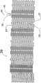
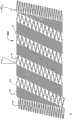
Figure 1A is the plane graph according to first embodiment of support of the present invention, and its medium-height trestle is to be shown as to be in not extended mode;
Figure 1B is the plane graph according to first embodiment of support of the present invention, and its medium-height trestle is to be shown as to be in extended mode;
Fig. 2 is the plane graph according to second embodiment of support of the present invention;
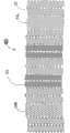
Fig. 3 is the plane graph according to the 3rd embodiment of support of the present invention;
Fig. 4 is the plane graph according to the 4th embodiment of support of the present invention;
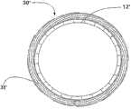
Fig. 5 is the cross-sectional end view according to the 5th embodiment of support of the present invention;
Fig. 6 is vertical side view of the embodiment identical with Fig. 5;
Fig. 7 A is the plane graph according to another embodiment of support of the present invention;
Fig. 7 B is the plane graph according to another embodiment of support of the present invention;
Fig. 8 is the cross-sectional end view according to another embodiment of support of the present invention;
Fig. 9 is vertical side view of the embodiment identical with Fig. 8;
Figure 10 A is that it comprises the graft materials that covers on the support outer surface according to the cross-sectional end view of an alternate embodiment of support of the present invention;
Figure 10 B is the cross-sectional end view according to an alternate embodiment of support of the present invention, and it comprises and covers the lip-deep graft materials of internal stent;
Figure 10 C is that it comprises the graft materials that covers on support outer surface and the inner surface according to the cross-sectional end view of an alternate embodiment of support of the present invention;
Figure 11 A is that it comprises the graft materials that is attached on the leg portion according to the side view of an alternate embodiment of support of the present invention, and said graft materials covers leg portion and spiral part;
Figure 11 B is the side view according to an alternate embodiment of support of the present invention, and it comprises that a plurality of biologies can compatible graft materials section, wherein can have a gap between each section of compatible graft materials section at said biology;
Figure 11 C is the side view according to an alternate embodiment of support of the present invention, and it comprises that a plurality of biologies can compatible graft materials section, and wherein the graft materials of adjacent sections overlaps;
Figure 11 D is the side view according to an alternate embodiment of support of the present invention, and it comprises that a biology can compatible graft materials, and said graft materials has a convexity in the spire office;
Figure 11 E is the side view according to an alternate embodiment of support of the present invention, and it comprises that a biology can compatible graft materials, and said graft materials has a plurality of longitudinal openings on spiral part;
Figure 11 F is that wherein said graft materials has a convexity in the spire office according to the side view of an alternate embodiment of support of the present invention, and said graft materials has a plurality of longitudinal openings on spiral part;
Figure 11 G is the side view according to an alternate embodiment of support of the present invention, and it comprises that a biology can compatible graft materials, and said graft materials has and the corresponding a plurality of spiral openings of screw assembly spacing;
Figure 11 H is the side view according to an alternate embodiment of support of the present invention, and it comprises a plurality of bio-compatible graft materials sections, and each section all is attached to holder part or spiral part is wherein arbitrary, wherein between each graft materials section, has a gap;
Figure 11 J is the side view according to an alternate embodiment of support of the present invention, and it comprises a plurality of bio-compatible graft materials sections, and each section all is attached to holder part or spiral part is wherein arbitrary, and wherein adjacent graft materials section overlaps;
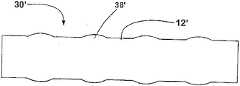
Figure 12 A is the plane graph in an alternate embodiment of the support of extended mode;
Figure 12 B is the plane graph of the support shown in Figure 12 A in rolled state, and is wherein all identical in whole spiral part in the gap between the screw assembly, and in addition, during in rolled state and in extended mode, the length of support is also all identical;
Figure 12 C is the plane graph of the support shown in Figure 12 A in rolled state, and wherein the gap between the screw assembly can change between whole spiral part, in addition, the length of support when rolled state greater than when the extended mode;
Figure 13 is the plane graph according to an alternate embodiment of support of the present invention.
Embodiment explanation in detail
Graphic below with reference to what follow, preferred embodiment is elaborated; In whole part graphic and explanation, identical reference marks is to be used for representing identical or similar part.
Figure 1A and Figure 1B are the plane graphs according to thesupport 10 of first embodiment of the invention, its show respectively support 10 extended mode not with in extended mode.Term as used herein " plane graph " is to be used to explain that one launches plane graph, and it can be envisioned as along one with the spool parallel of tubular bracket and be positioned at its outside line and open said tubular bracket; Hence one can see that, and in the support of reality, the top of Figure 1A will be incorporated in to lower edge.
Each spiral part all is made up of 18 of a plurality of in harness screw assemblies, its each axle screw winding alongsupport 10; The expansion of the radiation-curable upon deployment shape ofspiral part 14, and when a deployed condition be compressible, can expand andflexible.Screw assembly 18 can be connected between the relative wave part out of the ordinary of thestrut assemblies 16a ofdifferent leg portion 12; In this embodiment; Eachscrew assembly 18 can rotate along the generations onsupport 10 surfaces fully, yet it also can produce part rotation or more than once rotation.Spiral part preferably is configured as the repetition axial compression or the expansion that can produce about 20% (being preferably between 15% and 25%), and can be simultaneously with the about 13mm of minimum bending radius (being preferably between 10mm and 16mm) bending, and neither inefficacy.
Ifscrew assembly 18 is reeled with at least 90 degree between thestrut assemblies 16a that is connected toscrew assembly 18, just can produce preferable pliability and axial compression; Orscrew assembly 18 is to be wound between thestrut assemblies 16a that is connected toscrew assembly 18 with 360 degree.
Fig. 2 is the plane graph of the present invention one second embodiment, and it has been explained and support shown in Figure 1 10similar supports 20; Its basic difference is structure and the dextrorotation and the left-handed spiral part (being respectively 14R and 14L) ofleg portion 12 '.Each leg portion 12 ' comprises two adjacent Zhi Zhuhuan 26,27, and it connects through a short chain 28.Strut assemblies short chain 28, thereby each leg portion 12 ' has a dual pillar ring structure; Also can connect a plurality of Zhi Zhuhuan simultaneously and form a bigger leg portion.Advantage with leg portion of dual or multiple Zhi Zhuhuan is that it provides the radial rigidity bigger than the leg portion of single Zhi Zhuhuan, but and steady brace partly make it more can not receive the influence of axial forces.
In righthand helix part 14R,assembly 18 be surface alongsupport 10 to advance clockwise, in left-handedspiral part 14L, then advance withcounterclockwise.Screw assembly 18 floats basically, and can produce relatively large displacement along the support shaft between two pillar loop sections of arbitrary end; In this embodiment, can know that stent diameter at eachspiral part
Fig. 3 shows is support 30 according to another embodiment of the present invention, and thesupport 20 that itself and Fig. 2 showed is similar, exceptspiral part 34 comprises two-wayprogressive screw assembly 38;Screw assembly 38 is gone up two-way the advancing insupport 30 edges (advancing with counterclockwise earlier, then to advance clockwise) between the link position along different leg portion 12 ';Screw assembly 38 is to be wound to spike 35 with at least 90 degree from one first leg portion 12 ', and is wound to one second leg portion 12 ' fromspike 35 with 90 degree, to keep pliability.One-wayspiral assembly 18 shown in Figure 1A and Figure 1B can make adjacent leg portion relative to each other rotate;Bidirectional screw assembly 38 has then limited adjacent leg portion can be along support shaft, relative to each other and the amount of rotation, but still can provide axially and crooked pliability.
What Fig. 4 showed is the plane graph according to the support of fourth embodiment of the invention, and in this example,support 40 has leg portion 12 ' as shown in Figure 2 andspiral part
Fig. 5 is a sectional view, and it has shown the cross section perpendicular to the axle of thesupport 30 ' of fifth embodiment of the invention, and Fig. 6 is the side schematic view of same embodiment.Said support has structure as shown in Figure 3, except the diameter of its spiral part 38 ' than leg portion 12 ' bigger; Such construction mode can increase the radial rigidity of spiral part, but still reaches the degree lower than leg portion.
When all parts of support all have same diameter, when pillar is expanded, spiral part to the outward force of blood vessel maybe not can calcaneus branches post part as many; Geometric ways shown in Figure 6 can tend to force the more than leg portion of spiral part expansion, to increase the outward force of spiral part, and radial rigidity that it is balanced.
The Nitinol structure has the rigidity of skew, therefore when support is in its extended mode, the needed power of structure reverse reflex folding state generally can be received the required power of disease blood vessel greater than continuing to expand; In the nick-eltitanium alloy stent of expansion certainly of part, can use sacculus to come the expansion/expansion of secondary vessel.The rigidity of this skew is enough to support the blood vessel of unlatching, but outward force then possibly be not enough to open blood vessel (or possibly need one longer period).Therefore, using the support with geometric type as shown in Figure 5 to combine the auxiliary expansion of sacculus can be a kind of good scheme.
Fig. 7 A is the plane graph ofsupport 40B ' according to another embodiment of the present invention, andsupport 40B ' comprises pillar component 42, pillar component 42 from the end spirals ofsupport 40B ' to its other end; Pillar component 42 has formed the main body ofsupport 40B '.In this embodiment, each strut assemblies 44a is connected to the pillar of pillar component 42 next circle through screw assembly 46; In this embodiment, the screw assembly 46 ofspiral part 45 is spent less than 360 of a complete rotation along the amount ofsupport 40B ' spirals, and screw assembly 46 progressive directions and pillar component 42 are in the opposite direction alongsupport 40B ' spirals.
Be preferably, screw assembly 46 is adjacent one another are in the axial direction, and forms a kind of spring, and it can realize deflection degree and axial expansion largely, and pillar component 42 then provides radial strength, and makes support remain in its spread scenarios.
Fig. 7 B is the plane graph ofsupport 40C ' according to another embodiment of the present invention, and support 40C ' andsupport 40B ' are similar, and it comprises pillar component 42, pillar component 42 from the end spirals ofsupport 40C ' to its other end; Pillar component 42 has formed the main body ofsupport 40C '.In this embodiment, each strut assemblies 44a is connected to the pillar of pillar component 42 next circle through screw assembly 47; In this embodiment, screw assembly 47 is identical along the direction ofsupport 40C ' spirals with pillar component 42 along the direction ofsupport 40C ' spirals.The spiral part 49 that support 40C ' comprises transformation and leg portion 48 provide leg portion 48 in arbitrary end ofsupport 40C ' with the arbitrary end insupport 40C '.Leg portion 48 is reeled along the axle ofsupport 40C '; Leg portion 48 has acute angle A2; Acute angle A2 be formed at and the coil of the perpendicular plane of axle ofpillar 40C ' and leg portion 48 between; Acute angle A2 is less than acute angle A1, between the plane that acute angle A1 is formed at and the axle ofpillar 40C ' is perpendicular and the coil of pillar component 42.The spiral part 49 that changes interconnects of leg portion 48 or revolving coil still less.Leg portion 48 along the axle ofsupport 40C ' reel and the coil quantity that has be less than pillar component 42 the coil sum about 1/4.The quantity of spiralbranches column assembly 50 in a rotation of the coil of leg portion 48 is greater than the quantity of strut assemblies 44a in a rotation of pillar component 42.
The advantage ofsupport 40B ' and 40C ' is can be along stent length continuous distribution flexible screw assembly more, and more successive pliability can be provided.
Convention art technology personage can recognize that the various modifications of carrying out forsupport 40B ' or 40C ' all are feasible, and it is looked closely in the demand of particular design and decides.For example, possibly in specific circle, will be less than whole strut assemblies 44a and be connected to next circle, and reduce the quantity of screw assembly 46; Screw assembly 46 can be expanded less or expand with any integer or the non-integer multiple of a complete rotation.Support also can be made up of a plurality of tubular sections withsupport 40B ' or 40C ' construction mode, and on length, combines the section of another kind of type.
Fig. 8 is a sectional view, and it has shown the cross section perpendicular to the axle of the present invention's support 20 ', and Fig. 9 is the side schematic view of same embodiment.Shown in support have the structure shown in Figure 1A, except the diameter of spiral part 14 ' be narrowed than leg portion 12 ' little.In this construction mode, the spiral part that the force rate diameter that spire branch appears blood vessel wall is identical is little, and owing to the power of support to blood vessel wall reduces, the extent of damage that blood vessel is caused also can reduce, and the support of better performance can be provided.
Figure 10 A to Figure 10 C has shown thatstructural transplantation compatible graft materials 62 have covered the outside 64 ofstructural transplantation 60, shown in Figure 10 A; Or biology cancompatible graft materials 62 have covered the inside 74 ofstructural transplantation 70, shown in Figure 10 B; Orgraft materials 62 has covered theoutside 64 and inside 74 of support 80, shown in Figure 10 C.Butgraft materials 62 can or form lamellar or braiding surface and forming by the braiding of any amount of polymer or other biology compatible material; Or, also can apply the polymer and/or the medicine elution material of convention in this area to support.
Figure 11 A to Figure 11 J is the side view of structural transplantation, and said structural transplantation comprises said elastic support architectural feature of the present invention.
Such as in Figure 11 A demonstration, structural transplantation 100 comprises a kind of continuous covering graft materials 102, it covers support 10.102 of graft materials are attached to leg portion 12.Graft materials 102 covers, but non-cohesive tohelical form part 14.
Such as in Figure 11 B demonstration,structural transplantation 110 comprisesmost graft materials 112fragments 111 that cover said supportingstructure.Graft materials 112 is attached to leg portion 12.Graft materials 112 covers the part ofhelical form part 14 at least, but and is not attached to helical form part 14.115 positions, gap are between thecontiguous fragment 111 of graft materials 112.The size that has ongap 115 is general is between 20% length range of 0 (just not having the gap) and saidhelical form part 14.
Such as in Figure 11 C demonstration,structural transplantation 120 comprisesmost graft materials 122fragments 121 that cover said supportingstructure.Graft materials 122 is attached to leg portion 12.Graft materials 122 covershelical form parts 14, but and is not attached to helical form part 14.121 of the fragments of transplanting 122 have one and overlap 125 between thecontiguous fragment 121 that makes at graft materials 122.125 general going up between 40% length range of 0 (just not having the gap) and saidhelical form part 14 overlap.
Such as in Figure 11 D demonstration, structural transplantation 130 comprises a kind of continuous covering graft materials 132.Graft materials 132 is attached to leg portion 12.Graft materials 132 covers but is not attached to helical form part 14.Graft materials 132 then has soil block athelical form part 14 places.
Such as in Figure 11 E demonstration,structural transplantation 140 comprises a kind of continuous covering graft materials 142.Graft materials 142 has most thelongitudinal openings 144 that coverhelical form part 14 tops.
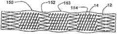
Such as in Figure 11 F demonstration,structural transplantation 150 comprises a kind of continuous covering graft materials 152.Graft materials 152 hasprojection 153 athelical form part 14 places, and abovehelical form part 14, has mostlongitudinal openings 154.
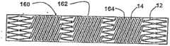
Such as in Figure 11 G demonstration,structural transplantation 160 comprises a kind of continuous covering graft materials 162.Graft materials 162 hashelical opening 164 inhelical form part 14, it is corresponding to the angle and the vertical separation ofhelical form part 14.
Such as in Figure 11 H demonstration,structural transplantation 170 comprisesmost graft materials 172fragments 171 that cover said support 10.Fragment 171 can be attached toleg portion 12 or helical form part 14.175 positions, gap are between thecontiguous fragment 171 of graft materials 172.The size that has ongap 175 is general is between 20% length range of 0 (just not having the gap) and saidhelical form part 14.
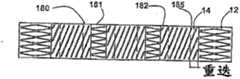
Such as in Figure 11 J demonstration,structural transplantation 180 comprisesmost graft materials 182fragments 181 that cover said support 10.Fragment 181 can be attached toleg portion 12 or helical form part 14.181 of the fragments ofgraft materials 182 have one and overlap 185 between thecontiguous fragment 181 that makes at graft materials 182.185 general going up between 40% length range of 0 (just not having the gap) and saidhelical form part 14 overlap.
Figure 12 A, 12B and 12C are the plane graphs of thesupport 200 according to the present invention.Figure 12 A shows the extended mode ofsupport 200, and it is distance gapped 202 between helical element 18.Figure 12 B and 12C showsupport 200
Two kinds of different compressive states.In Figure 12 B,support 200 is a compressive state, therefore spreads all overhelical form part 14, and thegap 212 between side-by-side helixlinear element 18 just is roughly the same.Between 212 sizes of the gap between the side-by-side helixlinear element 18 can between 0 and the size range of about said gap in extended mode between, for example, as shown in Figure 12 A.In other words, when said be when being of a size of 0, between side-by-side helixlinear element 18, do not have the space, and side-by-side helixlinear element 18 contacts with each other just.
The said helical element that in Figure 12 B, shows said support twines many times along said support; Therefore curl in the state said; At said said supporttotal length 211 of curling in the state is identical with the said supporttotal length 201 in said extended mode in Figure 12 A, eliminates the shortening situation by this.Interval between the coil of the interval between the coil of the pillar component 42 in said compressive state and thepillar component 12 in said deployed condition is identical in fact.
In Figure 12 C, support 200 is a compressive state, so helical element 18 is elongated, and the gap 222 between side-by-side helix linear element 18 then spreads all over axial length and the difference of helical form part 14.Between 222 sizes of the gap between the side-by-side helix linear element 18 can between 0 and the size range of about said gap 202 in extended mode between, for example, as shown in Figure 12 A.In other words, when said be when being of a size of 0, between side-by-side helix linear element 18, do not have the space, and side-by-side helix linear element 18 contacts with each other just.Helical form assembly 18 does not overlap in radial direction for the assembly that is elongated.In said deployed condition, helical form assembly 18 is parallel in fact.Pillar component 12 defines the cylinder with fixed diameter with helical form assembly 18.In Figure 12 C, curl said support total length 221 in the state greater than the said support total length 201 in said extended mode said.In other words; In said compressive state and deployed condition; Helical form assembly 18 is all the assembly that is elongated; Wherein in said compressive state, the distance between at least some adjacent helical form assemblies changes along with the length of said adjacent helical form assembly, and between 0 and big between the scope of the ultimate range between the adjacent helical form assembly described in the deployed condition.Interval between the coil of the pillar component 42 in said compressive state is greater than the interval between the coil of the pillar component in said deployed condition 12.Support 200 in the length in the compressive state shown in Figure 12 C greater than its length in the deployed condition shown in Figure 12 A.Minimum angles between the helical form assembly 18 in said compressive state and the longitudinal axis of support 200 is less than its minimum angles in said deployed condition.
Can provide another kind of method to curl said support, therefore at the said weak point of helical form partial-length ratio in said extended mode of curling in the state.For example; If the said support of Figure 12 A except between the side-by-side helix linear element, not existing the gap, is to utilize the same way as that is shown among Figure 12 B to curl; Said support will be shorter than the length in saidextended mode 201 in saidlength 211 of curling in the state to be had.In one embodiment, a kind of method of curling provides a kind of support, its curl with extended mode in total length identical, and curl in the state said, prop up part in helical element and do not have the gap.
As described above, a preferred embodiment of said support can be permitted about 20% repetition axial compression and expansion, and permits minimum bending radius simultaneously and be approximately 13 millimeters (mm) supports.The method that a kind of construction has a support of the present invention of concrete elasticity target is to change the ratio between this clearance space summation and said total length in said helical form part.Utilize the mode that increases said ratio, the elasticity of said support will increase.The chances are said support can follow the maximum axial compression of said ratio.What can know from experience is, for the consideration of safety, said maximum axial compression will receive the restriction that other similarly is the factor such as strain in said helical form part.
Figure 13 is the plane graph of one alternate embodiment of support 300 according to the present invention.Its above other embodiment that describe are the same for support 300, except it comprises the leg portion with different configurations and different axial lengths, and the different helical form part that disposes with different axial lengths.The position comprises long struts assembly 301 in the leg portion 302 of said support 300 outermost part.Long struts assembly 301 has length 311.The length 311 of long struts assembly 301 is greater than the length 312 of position in the leg portion 304 of said support 300 inside parts.On the end of said support, provide long struts assembly 301 can advantageously provide preferable fixing, and the zone that overlaps with near bracket is provided, but do not hinder the elasticity of said helical form part.In some vascular system, thigh knee joint postfovea tremulous pulse especially, the length that the length of the said tremulous pulse of falling ill maybe be very is usually greater than 10 centimetres.Possibly need most supports to treat the long segment of these tremulous pulsies of falling ill.General step in this situation is that near bracket is overlapped, and therefore covers the vascular of being treated.When some traditional support overlaps with the method, said mechanism will hinder its elasticity, and this artificially stiffening mode possibly cause many problems, comprise the support fracture.Advantage of the present invention is that permission bending and the assembly (helical form part) with axial elasticity are different with the assembly that radial structure is provided (leg portion); Therefore the leg portion near bracket just can overlap, and does not hinder the complete elasticity of the mobile and said support of said leg portion.
Thehelical form part 303 that is adjacent to saidleg portion 302 compriseshelical element 18, and it is linked to eachstrut assemblies 301 of leg portion 302.Helical form part 303 can provide the surface area of a high percentage ratio, so that the conveying optimization of medicament or other pharmacy media.304 of leg portion are utilizedhelical element 18; Eachstrut assemblies 16a place in saidleg portion 304sides 320 places; Be linked tohelical form part 303, and, be linked tohelical form part 309 at every anotherstrut assemblies 16a place at saidleg portion 304sides 321 places.Helical form part 309 provides the surface area and the bigger elasticity of low percentage ratio compared to helical form part 303.This collocation form can provide from having the stiffening helical form part of a high percentage ratio surface area, to a conversion than elastic helix shape part.
309 of helical form parts havelength 324 ratios of saidgap length 323 summations forhelical form part 309; Be higher thanlength 326 ratios of saidgap length 325 summations, so in generalhelical form part 309 will have bigger elasticity forhelical form part 303.
Said supporting structure of the present invention; Just be connected in the elastic helix shape part on the leg portion opposite side; A kind of optimization structure is provided, and wherein said leg portion can make born and non-stable helicoidal structure is stablized, and said helical form part then provides clean elasticity.In combining two-part different embodiment, then have the potentiality of design optimization in essence.
Said elastic support of the present invention and structural transplantation can utilize step as known in the art to be positioned among the vascular.Said elastic support and structural transplantation can be loaded in the proximal end of a conduit, and advance through said conduit, and discharge in the position of wanting.Alternate, said elastic support and structural transplantation also can be carried on the end near said conduit with a kind of compressive state, and discharge in the position of wanting.Said elastic support or structural transplantation also can have self-extended attribute, or to utilize similarly be that the segmental device of an expanding baloon of said conduit is expanded.After said support or structural transplantation have been placed on the inner chamber interior location of wanting, just regain said conduit.
Said elastic support of the present invention or structural transplantation can be placed among the bodily lumen, similarly are to comprise in the vascular or carrier pipe of human any mammalian species, and do not injure said internal chamber wall.For example, said elastic support can be placed among an infringement organ or the aneurysm, to treat said aneurysm.In one embodiment, after said elastic support can be placed on and be inserted into said vascular, be placed at once among the super large lower limb blood vessel, said elastic support or structural transplantation then provide the coverage rate of said vascular about at least 50%.
Though present preferred embodiment of the present invention discloses with purpose of description, art technology person can know from experience not deviating to utilize and follow under defined viewpoint of claim and the spirit, can carry out many interpolations, modification and replacement.For example, a support can be made as the helical form part that only has right-hand side or left-hand side, or said helical form part can have not only one majority turnover in coiling direction.Same, said helical form part also can have the rotation of any amount in the per unit length, or has a different height at interval, and said Zhi Zhuhuan and/or helical form part also can have different length in the direction along said support.
The explanation of assembly reference marks
Figure 1A and Figure 1B
Fig. 2
Leg portion 12 '
Fig. 3
Leg portion 12 '
Fig. 4
Leg portion 12 '
Fig. 5 and Fig. 6
Spiral part 38 '
Leg portion 12 '
Fig. 7 A to Fig. 7 C
Pillar component 42
Strut assemblies 44a
Screw assembly 46,47
Leg portion 48
Fig. 8 and Fig. 9
Spiral part 14 '
Leg portion 12 '
Figure 10 A to Figure 10 C
Biology cancompatible graft materials 62
The outside 64 of structural transplantation
The inside 74 of structural transplantation
Figure 11 A to Figure 11 J
Structural transplantation 100,110,120,130,140,150,160,170,180
Graft materials fragment 111,121,171,181
Graft materials 100,112,122,132,142,152,162,172,182
Overlap 125,185
Figure 12 A to Figure 12 C
Figure 13
Gap 202,212,222
Length 201,211
Long strutsassembly 301
Leg portion 302,304,306
Length 311,312
Side 320,321
Gap length 323,325
Thelength 324 ofhelical form part 309
14. thelength 326 ofhelical form part 303
Claims (13)
1. flexible stent comprises:
One pillar component, it is along the axle screw winding of said support, and said spiral pillar component comprises a plurality of strut assemblies; And
One spiral part; It comprises a plurality of discrete screw assemblies; Said spiral part with the equidirectional of said spiral pillar component axle screw winding along said support, said screw assembly extends between the position on following several coils of said spiral pillar component and interconnects;
Wherein said screw assembly is elongated when a compressive state;
Wherein when said compressive state, the size in the gap between at least some adjacent screw assemblies between 0 and the size of said gap in a deployed condition between;
Wherein said support is longer than it when said deployed condition when said compressive state.
2. support as claimed in claim 1 also comprises:
One leg portion, it is along the axle screw winding of said support, and said leg portion comprises a plurality of spiral branches column assemblies; Said leg portion is connected to an end of said spiral pillar component, and said leg portion is the spiral continuity of the coil of said spiral pillar component;
Wherein said leg portion be formed at and the coil of the perpendicular plane of axle of said support and said leg portion between an acute angle reel, said acute angle less than be formed at and the coil of plane that the axle of said support is perpendicular and said spiral pillar component between an acute angle; And
The spiral part of one transformation, it interconnects between a coil of said leg portion and said spiral pillar component; The spiral part of said transformation comprises the screw assembly of transformation; The screw assembly spirals of said transformation and connect the pillar spike of some spiral branches column assemblies of pillar spike and said leg portion of some spiral branches column assemblies of said spiral pillar component, the pillar spike of the spiral branches column assembly of said leg portion defines the said acute angle of said leg portion coil.
3. support as claimed in claim 1; Wherein at least some said screw assemblies between the position on following several coils of said spiral pillar component along the axle spiral extension and interconnecting of said support; When said support is in said deployed condition, around the said screw assembly distance spaced apart be said support girth 10% to less than 50% of said support girth.
4. support as claimed in claim 1; Wherein at least some said screw assemblies between the position on following several coils of said spiral pillar component along the axle spiral extension and interconnecting of said support; When said support is in said deployed condition, around the said screw assembly distance spaced apart be said support girth 50% to less than 100% of said support girth.
5. support as claimed in claim 1, wherein said support can be crooked and indeformable with radius 13mm.
6. support as claimed in claim 1, the length of wherein said support are little by about 20% when said deployed condition than in said compressive state the time.
7. expand flexible stent certainly for one kind, comprising:
One spiral pillar component, it is along the axle screw winding of said support, and said spiral pillar component comprises a plurality of spiral branches column assemblies;
A plurality of discrete screw assemblies, its with the equidirectional of said spiral pillar component axle screw winding along said support, said screw assembly extends between the position on following several coils of said spiral pillar component and interconnects;
One leg portion, it is along the axle screw winding of said support, and said leg portion comprises a plurality of spiral branches column assemblies; Said leg portion is connected to an end of said spiral pillar component; Said leg portion is the spiral continuity of the coil of said spiral pillar component; Said leg portion be formed at and the coil of the perpendicular plane of axle of said support and said leg portion between an acute angle reel, said acute angle less than be formed at and the coil of plane that the axle of said support is perpendicular and said spiral pillar component between an acute angle; And
The spiral part of one transformation, it interconnects between a coil of said leg portion and said spiral pillar component; The spiral part of said transformation comprises the screw assembly of transformation; The screw assembly spirals of said transformation and connect the pillar spike of some spiral branches column assemblies of pillar spike and said leg portion of some spiral branches column assemblies of said spiral pillar component, the pillar spike of the spiral branches column assembly of said leg portion defines the said acute angle of said leg portion coil; And the spiral part of said transformation interconnects along of said leg portion or revolving coil still less.
8. support as claimed in claim 7, the screw assembly of wherein adjacent said transformation have the length that increases or reduce gradually.
9. support as claimed in claim 7, wherein said leg portion along the axle of support reel and the coil quantity that has be less than said spiral pillar component the coil sum about 1/4.
10. support as claimed in claim 7, the quantity of wherein said spiral branches column assembly in a rotation of said leg portion coil is greater than the quantity of said spiral branches column assembly in a rotation of said spiral pillar member coils.
11. expand flexible stent certainly, comprising for one kind:
One spiral pillar component, it is along the axle screw winding of said support, and said spiral pillar component comprises a plurality of spiral branches column assemblies;
A plurality of discrete screw assemblies, its with the equidirectional of said spiral pillar component axle screw winding along said support, said screw assembly extends between the position on following several coils of said spiral pillar component and interconnects;
One leg portion, it is along the axle screw winding of said support, and said leg portion comprises a plurality of spiral branches column assemblies; Said leg portion is connected to an end of said spiral pillar component, and said leg portion is the spiral continuity of the coil of said spiral pillar component; Wherein said leg portion be formed at and the coil of the perpendicular plane of axle of said support and said leg portion between an acute angle reel, said acute angle less than be formed at and the coil of plane that the axle of said support is perpendicular and said spiral pillar component between an acute angle; And the spiral part of a transformation, it interconnects between a coil of said leg portion and said spiral pillar component; The spiral part of said transformation comprises the screw assembly of transformation; The screw assembly spirals of said transformation and connect the pillar spike of some spiral branches column assemblies of pillar spike and said leg portion of some spiral branches column assemblies of said spiral pillar component, the pillar spike of the spiral branches column assembly of said leg portion defines the said acute angle of the coil of said leg portion;
Wherein said screw assembly is all the assembly that is elongated in compressive state and deployed condition;
Wherein the minimum angles between the longitudinal axis of said screw assembly in said compressive state and said support is less than the minimum angles between the longitudinal axis of said screw assembly in said deployed condition and said support; And
Wherein the interval between following several coils of the interval between following several coils of the said spiral pillar component in said compressive state and said spiral pillar component in said deployed condition is identical in fact.
12. expand flexible stent certainly, comprising for one kind:
One spiral pillar component, it is along the axle screw winding of said support, and said spiral pillar component comprises a plurality of spiral branches column assemblies;
A plurality of discrete screw assemblies, its with the equidirectional of said spiral pillar component axle screw winding along said support, said screw assembly extends between the position on following several coils of said spiral pillar component and interconnects;
One leg portion, it is along the axle screw winding of said support, and said leg portion comprises a plurality of spiral branches column assemblies; Said leg portion is connected to an end of said spiral pillar component, and said leg portion is the spiral continuity of the coil of said spiral pillar component;
Wherein said leg portion be formed at and the coil of the perpendicular plane of axle of said support and said leg portion between an acute angle reel, said acute angle less than be formed at and the coil of plane that the axle of said support is perpendicular and said spiral pillar component between an acute angle; And the spiral part of a transformation, it interconnects between a coil of said leg portion and said spiral pillar component; The spiral part of said transformation comprises the screw assembly of transformation; The screw assembly spirals of said transformation and connect the pillar spike of some spiral branches column assemblies of pillar spike and said leg portion of some spiral branches column assemblies of said spiral pillar component, the pillar spike of the spiral branches column assembly of said leg portion defines the said acute angle of the coil of said leg portion;
Wherein said screw assembly is all the assembly that is elongated in compressive state and deployed condition;
Wherein said support is longer than it when said deployed condition when said compressive state;
Wherein the interval between following several coils of the said spiral pillar component in said compressive state is greater than the interval between following several coils of the said spiral pillar component in said deployed condition.
13. expand flexible stent certainly, comprising for one kind:
One spiral pillar component, it is along the axle screw winding of said support, and said spiral pillar component comprises a plurality of spiral branches column assemblies;
A plurality of discrete screw assemblies, its with the equidirectional of said spiral pillar component axle screw winding along said support, said screw assembly extends between the position on following several coils of said spiral pillar component and interconnects;
One leg portion, it is along the axle screw winding of said support, and said leg portion comprises a plurality of spiral branches column assemblies; Said leg portion is connected to an end of said spiral pillar component, and said leg portion is the spiral continuity of the coil of said spiral pillar component; Wherein said leg portion be formed at and the coil of the perpendicular plane of axle of said support and said leg portion between an acute angle reel, said acute angle less than be formed at and the coil of plane that the axle of said support is perpendicular and said spiral pillar component between an acute angle; And the spiral part of a transformation, it interconnects between a coil of said leg portion and said spiral pillar component; The spiral part of said transformation comprises the screw assembly of transformation; The screw assembly spirals of said transformation and connect the pillar spike of some spiral branches column assemblies of pillar spike and said leg portion of some spiral branches column assemblies of said spiral pillar component, the pillar spike of the spiral branches column assembly of said leg portion defines the said acute angle of the coil of said leg portion;
Wherein said screw assembly is all the assembly that is elongated in compressive state and deployed condition;
Wherein when said compressive state, the distance between at least some adjacent screw assemblies changes along with the length of said adjacent screw assembly, and when said deployed condition, said distance between 0 and said adjacent screw assembly between the scope of ultimate range in; And
Wherein the interval between following several coils of the interval between following several coils of the said spiral pillar component in said compressive state and said spiral pillar component in said deployed condition is identical in fact.
Applications Claiming Priority (6)
| Application Number | Priority Date | Filing Date | Title |
|---|---|---|---|
| US66761305P | 2005-04-04 | 2005-04-04 | |
| US60/667,613 | 2005-04-04 | ||
| US25022605A | 2005-10-14 | 2005-10-14 | |
| US11/250,226 | 2005-10-14 | ||
| US11/397,987 | 2006-04-04 | ||
| US11/397,987US7803180B2 (en) | 2005-04-04 | 2006-04-04 | Flexible stent |
Related Parent Applications (1)
| Application Number | Title | Priority Date | Filing Date |
|---|---|---|---|
| CN200680011292.2ADivisionCN101484089B (en) | 2005-04-04 | 2006-04-04 | Flexible stent |
Publications (2)
| Publication Number | Publication Date |
|---|---|
| CN102309370Atrue CN102309370A (en) | 2012-01-11 |
| CN102309370B CN102309370B (en) | 2015-04-15 |
Family
ID=37074053
Family Applications (3)
| Application Number | Title | Priority Date | Filing Date |
|---|---|---|---|
| CN201110281152.XAActiveCN102302390B (en) | 2005-04-04 | 2006-04-04 | Flexible stent |
| CN201110281185.4AActiveCN102309370B (en) | 2005-04-04 | 2006-04-04 | Flexible stent |
| CN200680011292.2AActiveCN101484089B (en) | 2005-04-04 | 2006-04-04 | Flexible stent |
Family Applications Before (1)
| Application Number | Title | Priority Date | Filing Date |
|---|---|---|---|
| CN201110281152.XAActiveCN102302390B (en) | 2005-04-04 | 2006-04-04 | Flexible stent |
Family Applications After (1)
| Application Number | Title | Priority Date | Filing Date |
|---|---|---|---|
| CN200680011292.2AActiveCN101484089B (en) | 2005-04-04 | 2006-04-04 | Flexible stent |
Country Status (9)
| Country | Link |
|---|---|
| US (4) | US7803180B2 (en) |
| EP (3) | EP2505166B1 (en) |
| JP (1) | JP5523700B2 (en) |
| CN (3) | CN102302390B (en) |
| AU (1) | AU2006231559B2 (en) |
| CA (1) | CA2610108C (en) |
| ES (1) | ES2764992T3 (en) |
| NZ (1) | NZ563119A (en) |
| WO (1) | WO2006108010A2 (en) |
Families Citing this family (100)
| Publication number | Priority date | Publication date | Assignee | Title |
|---|---|---|---|---|
| US7887578B2 (en) | 1998-09-05 | 2011-02-15 | Abbott Laboratories Vascular Enterprises Limited | Stent having an expandable web structure |
| US6682554B2 (en) | 1998-09-05 | 2004-01-27 | Jomed Gmbh | Methods and apparatus for a stent having an expandable web structure |
| US6755856B2 (en) | 1998-09-05 | 2004-06-29 | Abbott Laboratories Vascular Enterprises Limited | Methods and apparatus for stenting comprising enhanced embolic protection, coupled with improved protection against restenosis and thrombus formation |
| US7815763B2 (en)* | 2001-09-28 | 2010-10-19 | Abbott Laboratories Vascular Enterprises Limited | Porous membranes for medical implants and methods of manufacture |
| US20040267349A1 (en) | 2003-06-27 | 2004-12-30 | Kobi Richter | Amorphous metal alloy medical devices |
| US8382821B2 (en) | 1998-12-03 | 2013-02-26 | Medinol Ltd. | Helical hybrid stent |
| EP1542616B1 (en) | 2002-09-20 | 2015-04-22 | Endologix, Inc. | Stent-graft with positioning anchor |
| US9039755B2 (en)* | 2003-06-27 | 2015-05-26 | Medinol Ltd. | Helical hybrid stent |
| US9155639B2 (en) | 2009-04-22 | 2015-10-13 | Medinol Ltd. | Helical hybrid stent |
| US7763065B2 (en) | 2004-07-21 | 2010-07-27 | Reva Medical, Inc. | Balloon expandable crush-recoverable stent device |
| US8048145B2 (en) | 2004-07-22 | 2011-11-01 | Endologix, Inc. | Graft systems having filling structures supported by scaffolds and methods for their use |
| US8597716B2 (en)* | 2009-06-23 | 2013-12-03 | Abbott Cardiovascular Systems Inc. | Methods to increase fracture resistance of a drug-eluting medical device |
| US8292944B2 (en) | 2004-12-17 | 2012-10-23 | Reva Medical, Inc. | Slide-and-lock stent |
| JP5523700B2 (en)* | 2005-04-04 | 2014-06-18 | フレキシブル ステンティング ソリューションズ,インク. | Flexible stent |
| US8961585B2 (en)* | 2005-04-25 | 2015-02-24 | Covidien Lp | Controlled fracture connections for stents |
| JP2009500121A (en) | 2005-07-07 | 2009-01-08 | ネリックス・インコーポレーテッド | System and method for treatment of an intraluminal aneurysm |
| US9149378B2 (en) | 2005-08-02 | 2015-10-06 | Reva Medical, Inc. | Axially nested slide and lock expandable device |
| US7914574B2 (en) | 2005-08-02 | 2011-03-29 | Reva Medical, Inc. | Axially nested slide and lock expandable device |
| US7704275B2 (en) | 2007-01-26 | 2010-04-27 | Reva Medical, Inc. | Circumferentially nested expandable device |
| US9017395B2 (en)* | 2007-03-09 | 2015-04-28 | Novostent Corporation | Vascular prosthesis and methods of use |
| US8002815B2 (en)* | 2007-03-09 | 2011-08-23 | Novostent Corporation | Delivery system and method for vascular prosthesis |
| US20080221658A1 (en)* | 2007-03-09 | 2008-09-11 | Novostent Corporation | Vascular prosthesis and methods of use |
| US8348994B2 (en)* | 2007-03-09 | 2013-01-08 | Novostent Corporation | Vascular prosthesis with alternating helical sections |
| US8016874B2 (en) | 2007-05-23 | 2011-09-13 | Abbott Laboratories Vascular Enterprises Limited | Flexible stent with elevated scaffolding properties |
| US8128679B2 (en) | 2007-05-23 | 2012-03-06 | Abbott Laboratories Vascular Enterprises Limited | Flexible stent with torque-absorbing connectors |
| US7988723B2 (en)* | 2007-08-02 | 2011-08-02 | Flexible Stenting Solutions, Inc. | Flexible stent |
| EP2211773A4 (en) | 2007-11-30 | 2015-07-29 | Reva Medical Inc | Axially-radially nested expandable device |
| US8920488B2 (en)* | 2007-12-20 | 2014-12-30 | Abbott Laboratories Vascular Enterprises Limited | Endoprosthesis having a stable architecture |
| US8337544B2 (en) | 2007-12-20 | 2012-12-25 | Abbott Laboratories Vascular Enterprises Limited | Endoprosthesis having flexible connectors |
| US7850726B2 (en) | 2007-12-20 | 2010-12-14 | Abbott Laboratories Vascular Enterprises Limited | Endoprosthesis having struts linked by foot extensions |
| EP2242454A1 (en)* | 2008-02-13 | 2010-10-27 | Nellix, Inc. | Graft endoframe having axially variable characteristics |
| EP2278939B1 (en) | 2008-04-25 | 2021-04-14 | Endologix LLC | Stent graft delivery system |
| US10716573B2 (en) | 2008-05-01 | 2020-07-21 | Aneuclose | Janjua aneurysm net with a resilient neck-bridging portion for occluding a cerebral aneurysm |
| US8974487B2 (en) | 2008-05-01 | 2015-03-10 | Aneuclose Llc | Aneurysm occlusion device |
| US10028747B2 (en) | 2008-05-01 | 2018-07-24 | Aneuclose Llc | Coils with a series of proximally-and-distally-connected loops for occluding a cerebral aneurysm |
| EP2299931B1 (en) | 2008-06-04 | 2020-01-08 | Endologix, Inc. | Sealing apparatus |
| CA2726452A1 (en)* | 2008-06-04 | 2009-12-30 | Nellix, Inc. | Docking apparatus and methods of use |
| US20150039072A1 (en)* | 2008-07-31 | 2015-02-05 | Bradley Beach | Flexible stent |
| CA2734493C (en)* | 2008-08-19 | 2016-09-27 | Tissuegen, Inc. | Self-expanding medical device |
| EP2352465B1 (en)* | 2008-08-27 | 2018-03-21 | Cook Medical Technologies LLC | Multi-section stent |
| US9149376B2 (en) | 2008-10-06 | 2015-10-06 | Cordis Corporation | Reconstrainable stent delivery system |
| EP2331014B1 (en) | 2008-10-10 | 2017-08-09 | Reva Medical, Inc. | Expandable slide and lock stent |
| US9149377B2 (en)* | 2008-10-10 | 2015-10-06 | Veryan Medical Ltd. | Stent suitable for deployment in a blood vessel |
| US20100137974A1 (en)* | 2008-12-02 | 2010-06-03 | Boston Scientific Scimed, Inc. | Stent with Graduated Stiffness |
| KR101810379B1 (en) | 2009-02-02 | 2017-12-20 | 코디스 코포레이션 | Flexible stent design |
| EP2421470A4 (en)* | 2009-04-24 | 2016-03-30 | Flexible Stenting Solutions Inc | Flexible devices |
| EP2429453B1 (en)* | 2009-05-14 | 2021-01-27 | Orbusneich Medical Pte. Ltd | Self-expanding stent with polygon transition zone |
| US9060889B2 (en)* | 2009-09-18 | 2015-06-23 | Medtronic Vascular, Inc. | Methods for forming an orthogonal end on a helical stent |
| US8114149B2 (en)* | 2009-10-20 | 2012-02-14 | Svelte Medical Systems, Inc. | Hybrid stent with helical connectors |
| US10092427B2 (en) | 2009-11-04 | 2018-10-09 | Confluent Medical Technologies, Inc. | Alternating circumferential bridge stent design and methods for use thereof |
| US9358140B1 (en) | 2009-11-18 | 2016-06-07 | Aneuclose Llc | Stent with outer member to embolize an aneurysm |
| US8348987B2 (en)* | 2009-12-22 | 2013-01-08 | Cook Medical Technologies Llc | Balloon with scoring member |
| US20110276078A1 (en) | 2009-12-30 | 2011-11-10 | Nellix, Inc. | Filling structure for a graft system and methods of use |
| US8906057B2 (en) | 2010-01-04 | 2014-12-09 | Aneuclose Llc | Aneurysm embolization by rotational accumulation of mass |
| JP5809237B2 (en) | 2010-04-10 | 2015-11-10 | レヴァ メディカル、 インコーポレイテッドReva Medical, Inc. | Expandable slide lock stent |
| US8864811B2 (en) | 2010-06-08 | 2014-10-21 | Veniti, Inc. | Bi-directional stent delivery system |
| US9301864B2 (en) | 2010-06-08 | 2016-04-05 | Veniti, Inc. | Bi-directional stent delivery system |
| WO2011163236A2 (en) | 2010-06-21 | 2011-12-29 | Zorion Medical, Inc. | Bioabsorbable implants |
| US20120022578A1 (en)* | 2010-07-20 | 2012-01-26 | Cook Medical Technologies Llc | Frame-based vena cava filter |
| MX2013001444A (en)* | 2010-08-02 | 2013-03-12 | Cordis Corp | Flexible helical stent having different helical regions. |
| US9233014B2 (en)* | 2010-09-24 | 2016-01-12 | Veniti, Inc. | Stent with support braces |
| WO2012047308A1 (en) | 2010-10-08 | 2012-04-12 | Nitinol Devices And Components, Inc. | Alternating circumferential bridge stent design and methods for use thereof |
| US8986369B2 (en) | 2010-12-01 | 2015-03-24 | Zorion Medical, Inc. | Magnesium-based absorbable implants |
| US8801768B2 (en) | 2011-01-21 | 2014-08-12 | Endologix, Inc. | Graft systems having semi-permeable filling structures and methods for their use |
| US9028540B2 (en)* | 2011-03-25 | 2015-05-12 | Covidien Lp | Vascular stent with improved vessel wall apposition |
| EP2693980B1 (en) | 2011-04-06 | 2022-07-13 | Endologix LLC | System for endovascular aneurysm treatment |
| US9138232B2 (en) | 2011-05-24 | 2015-09-22 | Aneuclose Llc | Aneurysm occlusion by rotational dispensation of mass |
| CN102335052A (en)* | 2011-07-15 | 2012-02-01 | 南京微创医学科技有限公司 | Anti-restenosis digestive tract stent |
| WO2013134560A1 (en)* | 2012-03-07 | 2013-09-12 | Orbusneich Medical, Inc. | Medical device for implantation into luminal structures |
| JP6220386B2 (en) | 2012-05-14 | 2017-10-25 | シー・アール・バード・インコーポレーテッドC R Bard Incorporated | Uniformly expandable stent |
| US9254205B2 (en) | 2012-09-27 | 2016-02-09 | Covidien Lp | Vascular stent with improved vessel wall apposition |
| US20140114434A1 (en)* | 2012-10-22 | 2014-04-24 | Orbusneich Medical, Inc. | Medical device for implantation into luminal structures |
| US9566633B2 (en) | 2012-11-15 | 2017-02-14 | Vactronix Scientific, Inc. | Stents having a hybrid pattern and methods of manufacture |
| USD723165S1 (en) | 2013-03-12 | 2015-02-24 | C. R. Bard, Inc. | Stent |
| BR112015022688B1 (en) | 2013-03-14 | 2020-10-06 | Endologix, Inc. | METHOD FOR FORMING A MATERIAL IN SITU THROUGH INCREASING THE VOLUME OF AN EXPANDABLE MEMBER OF A MEDICAL DEVICE |
| JP2016512751A (en) | 2013-03-14 | 2016-05-09 | パルマズ サイエンティフィック, インコーポレイテッドPalmaz Scientific, Inc. | Integrated medical device, method for manufacturing the same, and method for using the same |
| US9408732B2 (en) | 2013-03-14 | 2016-08-09 | Reva Medical, Inc. | Reduced-profile slide and lock stent |
| DE102013104062A1 (en) | 2013-04-22 | 2014-10-23 | Novatech Sa | stent |
| AU2014284216B2 (en) | 2013-06-21 | 2017-10-05 | Boston Scientific Scimed, Inc. | Stent with deflecting connector |
| JP5586742B1 (en)* | 2013-06-28 | 2014-09-10 | 株式会社World Medish | High flexibility stent |
| CN105705118B (en) | 2013-09-12 | 2018-03-30 | 波士顿科学国际有限公司 | Support with anti-displacement connector |
| US9980835B2 (en) | 2013-10-22 | 2018-05-29 | Orbusneich Medical Inc. | Medical device for implantation into luminal structures incorporating corrugated structural elements |
| JP5550028B1 (en)* | 2014-01-27 | 2014-07-16 | 株式会社World Medish | High flexibility stent |
| JP5695259B1 (en)* | 2014-02-19 | 2015-04-01 | 株式会社World Medish | High flexibility stent |
| USD888245S1 (en) | 2014-03-14 | 2020-06-23 | Vactronix Scientific, Llc | Stent device |
| US10117763B2 (en) | 2014-03-18 | 2018-11-06 | Boston Scientific Scimed, Inc. | Reduced granulation and inflammation stent design |
| WO2016054536A1 (en) | 2014-10-02 | 2016-04-07 | Boston Scientific Scimed, Inc. | Controlled ingrowth feature for antimigration |
| WO2016065086A1 (en) | 2014-10-22 | 2016-04-28 | Boston Scientific Scimed, Inc. | Stent with flexible hinge |
| WO2016073597A1 (en) | 2014-11-06 | 2016-05-12 | Boston Scientific Scimed, Inc. | Tracheal stent |
| US10299948B2 (en)* | 2014-11-26 | 2019-05-28 | W. L. Gore & Associates, Inc. | Balloon expandable endoprosthesis |
| CN104490500B (en)* | 2014-12-25 | 2017-01-18 | 周玉杰 | Chain type coronary stent suitable for coronary artery tortuosity angulation lesion |
| JP6734097B2 (en)* | 2015-03-31 | 2020-08-05 | 康宏 正林 | Highly flexible stent |
| EP3763340B1 (en)* | 2016-03-24 | 2024-08-14 | Covidien LP | Vascular flow diversion |
| US11628077B2 (en)* | 2016-10-31 | 2023-04-18 | Razmodics Llc | Post deployment radial force recovery of biodegradable scaffolds |
| US10342686B2 (en)* | 2017-08-10 | 2019-07-09 | Covidien Lp | Thin film mesh hybrid for treating vascular defects |
| CN109662820B (en)* | 2019-01-31 | 2023-06-16 | 深圳市科奕顿生物医疗科技有限公司 | A self-expanding stent and its preparation method and application |
| CN113413256B (en)* | 2019-01-31 | 2023-06-02 | 深圳市科奕顿生物医疗科技有限公司 | Self-expanding stent |
| WO2021146021A1 (en) | 2020-01-13 | 2021-07-22 | Boston Scientific Scimed, Inc. | Anti-migration stent |
| CN113017753A (en)* | 2021-02-26 | 2021-06-25 | 珠海通桥医疗科技有限公司 | Blood vessel support |
| US20250221834A1 (en)* | 2024-01-09 | 2025-07-10 | Route 92 Medical, Inc. | Systems and methods for treating vascular disease |
Citations (4)
| Publication number | Priority date | Publication date | Assignee | Title |
|---|---|---|---|---|
| US5693085A (en)* | 1994-04-29 | 1997-12-02 | Scimed Life Systems, Inc. | Stent with collagen |
| CN1186423A (en)* | 1995-04-26 | 1998-07-01 | 梅迪诺尔有限公司 | Articulated stent |
| US6042597A (en)* | 1998-10-23 | 2000-03-28 | Scimed Life Systems, Inc. | Helical stent design |
| US20040122504A1 (en)* | 2002-12-24 | 2004-06-24 | Michael Hogendijk | Vascular prosthesis and methods of use |
Family Cites Families (261)
| Publication number | Priority date | Publication date | Assignee | Title |
|---|---|---|---|---|
| US4425908A (en) | 1981-10-22 | 1984-01-17 | Beth Israel Hospital | Blood clot filter |
| US4432132A (en)* | 1981-12-07 | 1984-02-21 | Bell Telephone Laboratories, Incorporated | Formation of sidewall oxide layers by reactive oxygen ion etching to define submicron features |
| US4665906A (en) | 1983-10-14 | 1987-05-19 | Raychem Corporation | Medical devices incorporating sim alloy elements |
| US5190546A (en) | 1983-10-14 | 1993-03-02 | Raychem Corporation | Medical devices incorporating SIM alloy elements |
| US5275622A (en) | 1983-12-09 | 1994-01-04 | Harrison Medical Technologies, Inc. | Endovascular grafting apparatus, system and method and devices for use therewith |
| US5102417A (en)* | 1985-11-07 | 1992-04-07 | Expandable Grafts Partnership | Expandable intraluminal graft, and method and apparatus for implanting an expandable intraluminal graft |
| US4813925A (en) | 1987-04-21 | 1989-03-21 | Medical Engineering Corporation | Spiral ureteral stent |
| US5133732A (en) | 1987-10-19 | 1992-07-28 | Medtronic, Inc. | Intravascular stent |
| US5266073A (en) | 1987-12-08 | 1993-11-30 | Wall W Henry | Angioplasty stent |
| IE73670B1 (en) | 1989-10-02 | 1997-07-02 | Medtronic Inc | Articulated stent |
| US5190540A (en) | 1990-06-08 | 1993-03-02 | Cardiovascular & Interventional Research Consultants, Inc. | Thermal balloon angioplasty |
| US5197978B1 (en) | 1991-04-26 | 1996-05-28 | Advanced Coronary Tech | Removable heat-recoverable tissue supporting device |
| FR2683449A1 (en)* | 1991-11-08 | 1993-05-14 | Cardon Alain | ENDOPROTHESIS FOR TRANSLUMINAL IMPLANTATION. |
| US5507767A (en) | 1992-01-15 | 1996-04-16 | Cook Incorporated | Spiral stent |
| US5683448A (en) | 1992-02-21 | 1997-11-04 | Boston Scientific Technology, Inc. | Intraluminal stent and graft |
| WO1995014500A1 (en) | 1992-05-01 | 1995-06-01 | Beth Israel Hospital | A stent |
| BR9405969A (en) | 1993-03-11 | 1996-02-06 | Medinol Ltd | Process of making a stent-type device from a wire stent-type device process to install a stent-type device and process of heating a nitinol-stent-type device |
| US5913897A (en) | 1993-09-16 | 1999-06-22 | Cordis Corporation | Endoprosthesis having multiple bridging junctions and procedure |
| GB2281865B (en) | 1993-09-16 | 1997-07-30 | Cordis Corp | Endoprosthesis having multiple laser welded junctions,method and procedure |
| US5989280A (en) | 1993-10-22 | 1999-11-23 | Scimed Lifesystems, Inc | Stent delivery apparatus and method |
| FR2714815B1 (en)* | 1994-01-10 | 1996-03-08 | Microfil Ind Sa | Elastic prosthesis to widen a duct, in particular a blood vessel. |
| US5733303A (en) | 1994-03-17 | 1998-03-31 | Medinol Ltd. | Flexible expandable stent |
| US5449373A (en)* | 1994-03-17 | 1995-09-12 | Medinol Ltd. | Articulated stent |
| US5843120A (en) | 1994-03-17 | 1998-12-01 | Medinol Ltd. | Flexible-expandable stent |
| US6165210A (en) | 1994-04-01 | 2000-12-26 | Gore Enterprise Holdings, Inc. | Self-expandable helical intravascular stent and stent-graft |
| CA2157575C (en)* | 1994-04-01 | 2000-03-07 | Lilip Lau | Self-expandable stent and stent-graft and method of using them |
| US5824041A (en) | 1994-06-08 | 1998-10-20 | Medtronic, Inc. | Apparatus and methods for placement and repositioning of intraluminal prostheses |
| DE69528216T2 (en) | 1994-06-17 | 2003-04-17 | Terumo K.K., Tokio/Tokyo | Process for the production of a permanent stent |
| US5545210A (en) | 1994-09-22 | 1996-08-13 | Advanced Coronary Technology, Inc. | Method of implanting a permanent shape memory alloy stent |
| EP0794726A4 (en) | 1994-10-20 | 1998-01-07 | Instent Inc | Cystoscope delivery system |
| IL115756A0 (en)* | 1994-10-27 | 1996-01-19 | Medinol Ltd | Stent fabrication method |
| US5836964A (en) | 1996-10-30 | 1998-11-17 | Medinol Ltd. | Stent fabrication method |
| CA2301351C (en) | 1994-11-28 | 2002-01-22 | Advanced Cardiovascular Systems, Inc. | Method and apparatus for direct laser cutting of metal stents |
| US5591226A (en) | 1995-01-23 | 1997-01-07 | Schneider (Usa) Inc. | Percutaneous stent-graft and method for delivery thereof |
| DE69622231T2 (en) | 1995-03-01 | 2002-12-05 | Scimed Life Systems, Inc. | LENGTHFLEXIBLE AND EXPANDABLE STENT |
| US7204848B1 (en) | 1995-03-01 | 2007-04-17 | Boston Scientific Scimed, Inc. | Longitudinally flexible expandable stent |
| US6896696B2 (en) | 1998-11-20 | 2005-05-24 | Scimed Life Systems, Inc. | Flexible and expandable stent |
| US5591197A (en) | 1995-03-14 | 1997-01-07 | Advanced Cardiovascular Systems, Inc. | Expandable stent forming projecting barbs and method for deploying |
| DE69626108T2 (en) | 1995-04-14 | 2003-11-20 | Boston Scientific Ltd., St. Michael | STENTING DEVICE WITH ROLLING MEMBRANE |
| FI974063L (en)* | 1995-04-26 | 1997-12-19 | Medinol Ltd | Articulated expander |
| US6602281B1 (en) | 1995-06-05 | 2003-08-05 | Avantec Vascular Corporation | Radially expansible vessel scaffold having beams and expansion joints |
| US5788707A (en) | 1995-06-07 | 1998-08-04 | Scimed Life Systems, Inc. | Pull back sleeve system with compression resistant inner shaft |
| US5776161A (en) | 1995-10-16 | 1998-07-07 | Instent, Inc. | Medical stents, apparatus and method for making same |
| AU7458596A (en) | 1995-10-20 | 1997-05-07 | Bandula Wijay | Vascular stent |
| US5913896A (en) | 1995-11-28 | 1999-06-22 | Medtronic, Inc. | Interwoven dual sinusoidal helix stent |
| AR005140A1 (en) | 1995-12-21 | 1999-04-14 | Cornell Res Foundation Inc | AN ISOLATED DNA MOLECULE THAT CODES A PROTEIN OR POLYPEPTIDE OF A VINE LEAF WINDING VIRUS, AN EXPRESSION SYSTEM, A GUEST CELL OR A TRANSGENIC RHYDOMA, INCLUDING SUCH MOLECULA DNA FROM MOLECULA TRANSPLANT, A METHOD FOR |
| EP1011889B1 (en) | 1996-01-30 | 2002-10-30 | Medtronic, Inc. | Articles for and methods of making stents |
| EP1066804B1 (en) | 1996-03-05 | 2004-07-14 | Evysio Medical Devices Ulc | Expandable stent |
| DE69725120T2 (en) | 1996-03-07 | 2004-07-08 | Med Institute, Inc., West Lafayette | SPREADABLE STENT |
| US6334871B1 (en) | 1996-03-13 | 2002-01-01 | Medtronic, Inc. | Radiopaque stent markers |
| IL117472A0 (en) | 1996-03-13 | 1996-07-23 | Instent Israel Ltd | Radiopaque stent markers |
| US5649949A (en) | 1996-03-14 | 1997-07-22 | Target Therapeutics, Inc. | Variable cross-section conical vasoocclusive coils |
| US5833699A (en) | 1996-04-10 | 1998-11-10 | Chuter; Timothy A. M. | Extending ribbon stent |
| FR2747301B1 (en) | 1996-04-10 | 1998-09-18 | Nycomed Lab Sa | IMPLANTABLE DEVICE FOR MAINTAINING OR RE-ESTABLISHING THE NORMAL PASSAGE SECTION OF A BODY DUCT, AS WELL AS A SYSTEM FOR ITS PLACEMENT |
| US6039756A (en) | 1996-04-26 | 2000-03-21 | Jang; G. David | Intravascular stent |
| US5954743A (en) | 1996-04-26 | 1999-09-21 | Jang; G. David | Intravascular stent |
| US5669932A (en)* | 1996-05-29 | 1997-09-23 | Isostent, Inc. | Means for accurately positioning an expandable stent |
| US5697971A (en) | 1996-06-11 | 1997-12-16 | Fischell; Robert E. | Multi-cell stent with cells having differing characteristics |
| US5755781A (en) | 1996-08-06 | 1998-05-26 | Iowa-India Investments Company Limited | Embodiments of multiple interconnected stents |
| DE19633901A1 (en)* | 1996-08-22 | 1998-02-26 | Thomas Prof Dr Med Ischinger | Vascular support in the form of a tube section-like support structure |
| US5807404A (en) | 1996-09-19 | 1998-09-15 | Medinol Ltd. | Stent with variable features to optimize support and method of making such stent |
| US6325826B1 (en) | 1998-01-14 | 2001-12-04 | Advanced Stent Technologies, Inc. | Extendible stent apparatus |
| US5776142A (en) | 1996-12-19 | 1998-07-07 | Medtronic, Inc. | Controllable stent delivery system and method |
| US6551350B1 (en) | 1996-12-23 | 2003-04-22 | Gore Enterprise Holdings, Inc. | Kink resistant bifurcated prosthesis |
| US5906759A (en)* | 1996-12-26 | 1999-05-25 | Medinol Ltd. | Stent forming apparatus with stent deforming blades |
| FR2758253B1 (en) | 1997-01-10 | 1999-04-02 | Nycomed Lab Sa | IMPLANTABLE DEVICE FOR THE TREATMENT OF A BODY DUCT |
| US5925061A (en) | 1997-01-13 | 1999-07-20 | Gore Enterprise Holdings, Inc. | Low profile vascular stent |
| US6241757B1 (en) | 1997-02-04 | 2001-06-05 | Solco Surgical Instrument Co., Ltd. | Stent for expanding body's lumen |
| US5827321A (en) | 1997-02-07 | 1998-10-27 | Cornerstone Devices, Inc. | Non-Foreshortening intraluminal prosthesis |
| ES2297092T3 (en) | 1997-02-11 | 2008-05-01 | Warsaw Orthopedic, Inc. | PREVIOUS CERVICAL PLATE OF UNIQUE BLOCK. |
| FR2760351B1 (en) | 1997-03-04 | 1999-05-28 | Bernard Glatt | HELICAL STENT FORMING DEVICE AND MANUFACTURING METHOD THEREOF |
| US5911732A (en) | 1997-03-10 | 1999-06-15 | Johnson & Johnson Interventional Systems, Co. | Articulated expandable intraluminal stent |
| US5810872A (en)* | 1997-03-14 | 1998-09-22 | Kanesaka; Nozomu | Flexible stent |
| US5792144A (en) | 1997-03-31 | 1998-08-11 | Cathco, Inc. | Stent delivery catheter system |
| US5718713A (en) | 1997-04-10 | 1998-02-17 | Global Therapeutics, Inc. | Surgical stent having a streamlined contour |
| US6273913B1 (en)* | 1997-04-18 | 2001-08-14 | Cordis Corporation | Modified stent useful for delivery of drugs along stent strut |
| US6033433A (en)* | 1997-04-25 | 2000-03-07 | Scimed Life Systems, Inc. | Stent configurations including spirals |
| US5741327A (en) | 1997-05-06 | 1998-04-21 | Global Therapeutics, Inc. | Surgical stent featuring radiopaque markers |
| DE29708879U1 (en) | 1997-05-20 | 1997-07-31 | Jomed Implantate GmbH, 72414 Rangendingen | Coronary stent |
| US5891192A (en) | 1997-05-22 | 1999-04-06 | The Regents Of The University Of California | Ion-implanted protein-coated intralumenal implants |
| BE1011180A6 (en) | 1997-05-27 | 1999-06-01 | Medicorp R & D Benelux Sa | Luminal endoprosthesis AUTO EXPANDABLE. |
| US5913895A (en) | 1997-06-02 | 1999-06-22 | Isostent, Inc. | Intravascular stent with enhanced rigidity strut members |
| EP0884029B1 (en) | 1997-06-13 | 2004-12-22 | Gary J. Becker | Expandable intraluminal endoprosthesis |
| EP0890346A1 (en) | 1997-06-13 | 1999-01-13 | Gary J. Becker | Expandable intraluminal endoprosthesis |
| US5843175A (en) | 1997-06-13 | 1998-12-01 | Global Therapeutics, Inc. | Enhanced flexibility surgical stent |
| FR2764794B1 (en) | 1997-06-20 | 1999-11-12 | Nycomed Lab Sa | EXPANDED TUBULAR DEVICE WITH VARIABLE THICKNESS |
| IL121316A (en) | 1997-07-15 | 2001-07-24 | Litana Ltd | Implantable medical device of shape memory alloy |
| US6340367B1 (en) | 1997-08-01 | 2002-01-22 | Boston Scientific Scimed, Inc. | Radiopaque markers and methods of using the same |
| US5824059A (en)* | 1997-08-05 | 1998-10-20 | Wijay; Bandula | Flexible stent |
| JP4292710B2 (en)* | 1997-09-24 | 2009-07-08 | エム イー ディ インスチィチュート インク | Radially expandable stent |
| NO311781B1 (en) | 1997-11-13 | 2002-01-28 | Medinol Ltd | Metal multilayer stents |
| US6156062A (en) | 1997-12-03 | 2000-12-05 | Ave Connaught | Helically wrapped interlocking stent |
| US6022374A (en) | 1997-12-16 | 2000-02-08 | Cardiovasc, Inc. | Expandable stent having radiopaque marker and method |
| US6626939B1 (en) | 1997-12-18 | 2003-09-30 | Boston Scientific Scimed, Inc. | Stent-graft with bioabsorbable structural support |
| US6190406B1 (en) | 1998-01-09 | 2001-02-20 | Nitinal Development Corporation | Intravascular stent having tapered struts |
| US6719779B2 (en) | 2000-11-07 | 2004-04-13 | Innercool Therapies, Inc. | Circulation set for temperature-controlled catheter and method of using the same |
| US6533807B2 (en) | 1998-02-05 | 2003-03-18 | Medtronic, Inc. | Radially-expandable stent and delivery system |
| US6676696B1 (en) | 1998-02-12 | 2004-01-13 | Thomas R. Marotta | Endovascular prosthesis |
| EP1065993B1 (en) | 1998-03-05 | 2010-08-11 | Boston Scientific Limited | Intraluminal stent |
| US6019778A (en) | 1998-03-13 | 2000-02-01 | Cordis Corporation | Delivery apparatus for a self-expanding stent |
| US7179289B2 (en) | 1998-03-30 | 2007-02-20 | Conor Medsystems, Inc. | Expandable medical device for delivery of beneficial agent |
| US6241762B1 (en)* | 1998-03-30 | 2001-06-05 | Conor Medsystems, Inc. | Expandable medical device with ductile hinges |
| US6264687B1 (en) | 1998-04-20 | 2001-07-24 | Cordis Corporation | Multi-laminate stent having superelastic articulated sections |
| US6168621B1 (en) | 1998-05-29 | 2001-01-02 | Scimed Life Systems, Inc. | Balloon expandable stent with a self-expanding portion |
| US6740113B2 (en) | 1998-05-29 | 2004-05-25 | Scimed Life Systems, Inc. | Balloon expandable stent with a self-expanding portion |
| AU756080B2 (en) | 1998-06-04 | 2003-01-02 | New York University | Endovascular thin film devices and methods for treating and preventing stroke |
| US6261319B1 (en) | 1998-07-08 | 2001-07-17 | Scimed Life Systems, Inc. | Stent |
| US5911754A (en)* | 1998-07-24 | 1999-06-15 | Uni-Cath Inc. | Flexible stent with effective strut and connector patterns |
| DE19839646A1 (en) | 1998-08-31 | 2000-03-09 | Jomed Implantate Gmbh | Stent |
| US6093194A (en) | 1998-09-14 | 2000-07-25 | Endocare, Inc. | Insertion device for stents and methods for use |
| DE29816878U1 (en) | 1998-09-21 | 1998-12-24 | Schmitz-Rode, Thomas, Dipl.-Ing. Dr.med., 52070 Aachen | Helix stent that can be manufactured using the cutting process |
| US6544278B1 (en) | 1998-11-06 | 2003-04-08 | Scimed Life Systems, Inc. | Rolling membrane stent delivery system |
| US6059813A (en) | 1998-11-06 | 2000-05-09 | Scimed Life Systems, Inc. | Rolling membrane stent delivery system |
| CA2289169A1 (en) | 1998-11-11 | 2000-05-11 | Ogawa Spring Co., Ltd. | Stent, manufacturing method thereof and indwelling method thereof |
| DE69937415T2 (en)* | 1998-11-20 | 2008-02-14 | Boston Scientific Ltd., St. Michael | Longitudinally flexible and expandable stent |
| US6503270B1 (en) | 1998-12-03 | 2003-01-07 | Medinol Ltd. | Serpentine coiled ladder stent |
| US6355059B1 (en) | 1998-12-03 | 2002-03-12 | Medinol, Ltd. | Serpentine coiled ladder stent |
| SG75982A1 (en) | 1998-12-03 | 2000-10-24 | Medinol Ltd | Controlled detachment stents |
| US6743252B1 (en) | 1998-12-18 | 2004-06-01 | Cook Incorporated | Cannula stent |
| US6254609B1 (en) | 1999-01-11 | 2001-07-03 | Scimed Life Systems, Inc. | Self-expanding stent delivery system with two sheaths |
| EP1020166A1 (en) | 1999-01-12 | 2000-07-19 | Orbus Medical Technologies, Inc. | Expandable intraluminal endoprosthesis |
| US6632236B2 (en)* | 1999-03-12 | 2003-10-14 | Arteria Medical Science, Inc. | Catheter having radially expandable main body |
| US6287333B1 (en) | 1999-03-15 | 2001-09-11 | Angiodynamics, Inc. | Flexible stent |
| US6899730B1 (en) | 1999-04-15 | 2005-05-31 | Scimed Life Systems, Inc. | Catheter-stent device |
| US6860899B1 (en) | 1999-04-15 | 2005-03-01 | Boston Scientific Scimed, Inc. | Method for treating neurovascular aneurysms |
| US6730116B1 (en) | 1999-04-16 | 2004-05-04 | Medtronic, Inc. | Medical device for intraluminal endovascular stenting |
| US6273911B1 (en) | 1999-04-22 | 2001-08-14 | Advanced Cardiovascular Systems, Inc. | Variable strength stent |
| US6245101B1 (en)* | 1999-05-03 | 2001-06-12 | William J. Drasler | Intravascular hinge stent |
| US6673103B1 (en) | 1999-05-20 | 2004-01-06 | Scimed Life Systems, Inc. | Mesh and stent for increased flexibility |
| US6551351B2 (en)* | 1999-07-02 | 2003-04-22 | Scimed Life Systems | Spiral wound stent |
| US6485507B1 (en) | 1999-07-28 | 2002-11-26 | Scimed Life Systems | Multi-property nitinol by heat treatment |
| US6142987A (en) | 1999-08-03 | 2000-11-07 | Scimed Life Systems, Inc. | Guided filter with support wire and methods of use |
| US6302907B1 (en) | 1999-10-05 | 2001-10-16 | Scimed Life Systems, Inc. | Flexible endoluminal stent and process of manufacture |
| AU1084101A (en) | 1999-10-14 | 2001-04-23 | United Stenting, Inc. | Stents with multilayered struts |
| US6171328B1 (en) | 1999-11-09 | 2001-01-09 | Embol-X, Inc. | Intravascular catheter filter with interlocking petal design and methods of use |
| US6264671B1 (en) | 1999-11-15 | 2001-07-24 | Advanced Cardiovascular Systems, Inc. | Stent delivery catheter and method of use |
| US6585758B1 (en) | 1999-11-16 | 2003-07-01 | Scimed Life Systems, Inc. | Multi-section filamentary endoluminal stent |
| CN1186423C (en) | 1999-12-03 | 2005-01-26 | 中国科学院南京土壤研究所 | Process for preparing ammonia suppressing film of rice field |
| EP1242004B1 (en) | 1999-12-21 | 2004-12-08 | Imperial College of Science, Technology and Medicine | Vascular stents |
| US6334866B1 (en) | 2000-01-14 | 2002-01-01 | William H. Wall | Stent device for performing endovascular repair of aneurysms |
| US6723119B2 (en) | 2000-03-01 | 2004-04-20 | Medinol Ltd. | Longitudinally flexible stent |
| US7758627B2 (en) | 2000-03-01 | 2010-07-20 | Medinol, Ltd. | Longitudinally flexible stent |
| US7828835B2 (en) | 2000-03-01 | 2010-11-09 | Medinol Ltd. | Longitudinally flexible stent |
| SG86458A1 (en) | 2000-03-01 | 2002-02-19 | Medinol Ltd | Longitudinally flexible stent |
| US6953476B1 (en) | 2000-03-27 | 2005-10-11 | Neovasc Medical Ltd. | Device and method for treating ischemic heart disease |
| US6352552B1 (en)* | 2000-05-02 | 2002-03-05 | Scion Cardio-Vascular, Inc. | Stent |
| US8236048B2 (en) | 2000-05-12 | 2012-08-07 | Cordis Corporation | Drug/drug delivery systems for the prevention and treatment of vascular disease |
| US6423091B1 (en) | 2000-05-16 | 2002-07-23 | Cordis Corporation | Helical stent having flat ends |
| JP2003533335A (en)* | 2000-05-22 | 2003-11-11 | オーバス メディカル テクノロジーズ インク. | Self-expanding stent |
| AU2001275100A1 (en) | 2000-05-31 | 2001-12-11 | Courtney, Brian K. | Embolization protection system for vascular procedures |
| US8298257B2 (en) | 2000-06-29 | 2012-10-30 | Concentric Medical, Inc. | Systems, methods and devices for removing obstructions from a blood vessel |
| US20020077693A1 (en) | 2000-12-19 | 2002-06-20 | Barclay Bruce J. | Covered, coiled drug delivery stent and method |
| US6540775B1 (en) | 2000-06-30 | 2003-04-01 | Cordis Corporation | Ultraflexible open cell stent |
| US6969401B1 (en) | 2000-08-18 | 2005-11-29 | Marotta Thomas R | Endovascular prosthesis |
| US6565595B1 (en) | 2000-09-18 | 2003-05-20 | Scimed Life Systems, Inc. | Two component sleeves |
| US6607552B1 (en) | 2000-09-18 | 2003-08-19 | Scimed Life Systems, Inc. | Rolling socks |
| US6805898B1 (en) | 2000-09-28 | 2004-10-19 | Advanced Cardiovascular Systems, Inc. | Surface features of an implantable medical device |
| US6492615B1 (en) | 2000-10-12 | 2002-12-10 | Scimed Life Systems, Inc. | Laser polishing of medical devices |
| US7163552B2 (en) | 2000-10-13 | 2007-01-16 | Medtronic Vascular, Inc. | Stent delivery system with hydraulic deployment |
| US6663664B1 (en) | 2000-10-26 | 2003-12-16 | Advanced Cardiovascular Systems, Inc. | Self-expanding stent with time variable radial force |
| US6506211B1 (en) | 2000-11-13 | 2003-01-14 | Scimed Life Systems, Inc. | Stent designs |
| US6843802B1 (en) | 2000-11-16 | 2005-01-18 | Cordis Corporation | Delivery apparatus for a self expanding retractable stent |
| US6579308B1 (en) | 2000-11-28 | 2003-06-17 | Scimed Life Systems, Inc. | Stent devices with detachable distal or proximal wires |
| US6517567B2 (en) | 2000-11-30 | 2003-02-11 | Albert R. Bass, Jr. | Apparatus and method for pacifier withdrawal |
| JP4323102B2 (en) | 2001-01-15 | 2009-09-02 | テルモ株式会社 | Flexible stent |
| WO2002054989A2 (en)* | 2001-01-15 | 2002-07-18 | Terumo Corp | Stent |
| JP4727070B2 (en) | 2001-06-01 | 2011-07-20 | テルモ株式会社 | Stent |
| US7169165B2 (en) | 2001-01-16 | 2007-01-30 | Boston Scientific Scimed, Inc. | Rapid exchange sheath for deployment of medical devices and methods of use |
| US6899727B2 (en) | 2001-01-22 | 2005-05-31 | Gore Enterprise Holdings, Inc. | Deployment system for intraluminal devices |
| US6736839B2 (en) | 2001-02-01 | 2004-05-18 | Charles Cummings | Medical device delivery system |
| US6563080B2 (en) | 2001-02-15 | 2003-05-13 | Scimed Life Systems, Inc. | Laser cutting of stents and other medical devices |
| US6679911B2 (en)* | 2001-03-01 | 2004-01-20 | Cordis Corporation | Flexible stent |
| US6613077B2 (en) | 2001-03-27 | 2003-09-02 | Scimed Life Systems, Inc. | Stent with controlled expansion |
| GB0107910D0 (en) | 2001-03-29 | 2001-05-23 | Isis Innovation | Deployable stent |
| EP1245203B1 (en) | 2001-03-30 | 2006-03-08 | Terumo Kabushiki Kaisha | Stent |
| DE60237813D1 (en) | 2001-05-11 | 2010-11-11 | Epion Corp | METHOD FOR IMPROVING THE EFFECTIVENESS OF MEDICAL DEVICES BY MOUNTING MEDICAMENTS ON THE SURFACE |
| US6599314B2 (en) | 2001-06-08 | 2003-07-29 | Cordis Corporation | Apparatus and method for stenting a vessel using balloon-actuated stent with interlocking elements |
| US6612012B2 (en) | 2001-06-11 | 2003-09-02 | Cordis Neurovascular, Inc. | Method of manufacturing small profile medical devices |
| US6673106B2 (en) | 2001-06-14 | 2004-01-06 | Cordis Neurovascular, Inc. | Intravascular stent device |
| US6818013B2 (en) | 2001-06-14 | 2004-11-16 | Cordis Corporation | Intravascular stent device |
| US6796999B2 (en) | 2001-09-06 | 2004-09-28 | Medinol Ltd. | Self articulating stent |
| JP2005501651A (en) | 2001-09-10 | 2005-01-20 | メディノール リミテッド | Longitudinal flexible stent [Related application] This application is a continuation-in-part of application No. 09 / 864,389, filed on May 25, 2001, and is filed on February 28, 2001. No. 09 / 795,794, a continuation-in-part application, which is an application of application No. 09 / 516,753 filed on Mar. 1, 2000. Claims priority of provisional application 60 / 202,723 of monthly application. |
| US20030229390A1 (en) | 2001-09-17 | 2003-12-11 | Control Delivery Systems, Inc. | On-stent delivery of pyrimidines and purine analogs |
| US7175655B1 (en) | 2001-09-17 | 2007-02-13 | Endovascular Technologies, Inc. | Avoiding stress-induced martensitic transformation in nickel titanium alloys used in medical devices |
| JP3605388B2 (en) | 2001-10-16 | 2004-12-22 | 川澄化学工業株式会社 | Stent |
| US20050070992A1 (en) | 2001-11-28 | 2005-03-31 | Aptus Endosystems, Inc. | Prosthesis systems and methods sized and configured for the receipt and retention of fasteners |
| JP4331610B2 (en) | 2001-12-20 | 2009-09-16 | トリバスキュラー2,インコーポレイティド | Advanced endovascular graft |
| US7163553B2 (en) | 2001-12-28 | 2007-01-16 | Advanced Cardiovascular Systems, Inc. | Intravascular stent and method of use |
| US6981985B2 (en) | 2002-01-22 | 2006-01-03 | Boston Scientific Scimed, Inc. | Stent bumper struts |
| US7354450B2 (en)* | 2002-01-30 | 2008-04-08 | Boston Scientific Scimed, Inc. | Stent with wishbone connectors and serpentine bands |
| US7445629B2 (en) | 2002-01-31 | 2008-11-04 | Boston Scientific Scimed, Inc. | Medical device for delivering biologically active material |
| US7169170B2 (en) | 2002-02-22 | 2007-01-30 | Cordis Corporation | Self-expanding stent delivery system |
| US7052511B2 (en) | 2002-04-04 | 2006-05-30 | Scimed Life Systems, Inc. | Delivery system and method for deployment of foreshortening endoluminal devices |
| US20030195609A1 (en)* | 2002-04-10 | 2003-10-16 | Scimed Life Systems, Inc. | Hybrid stent |
| US20030204244A1 (en) | 2002-04-26 | 2003-10-30 | Stiger Mark L. | Aneurysm exclusion stent |
| DE10219014A1 (en) | 2002-04-27 | 2003-11-13 | Ruesch Willy Gmbh | Self-expanding stent for reinforcing and/or keeping open a hollow organ comprise two elastic tubular layers which bracket and positionally fix at least one helical filament |
| US7122048B2 (en) | 2002-05-03 | 2006-10-17 | Scimed Life Systems, Inc. | Hypotube endoluminal device |
| US7128756B2 (en) | 2002-05-08 | 2006-10-31 | Abbott Laboratories | Endoprosthesis having foot extensions |
| WO2003096935A1 (en) | 2002-05-16 | 2003-11-27 | Cook Incorporated | Flexible barb for anchoring a prosthesis |
| CA2678623C (en) | 2002-05-17 | 2011-07-19 | The Viking Corporation | Fire protection system |
| US6830638B2 (en) | 2002-05-24 | 2004-12-14 | Advanced Cardiovascular Systems, Inc. | Medical devices configured from deep drawn nickel-titanium alloys and nickel-titanium clad alloys and method of making the same |
| US20040002752A1 (en) | 2002-06-26 | 2004-01-01 | Scimed Life Systems, Inc. | Sacrificial anode stent system |
| US8080052B2 (en) | 2002-06-28 | 2011-12-20 | Cordis Corporation | Stent with diagonal flexible connecting links |
| US6761731B2 (en) | 2002-06-28 | 2004-07-13 | Cordis Corporation | Balloon-stent interaction to help reduce foreshortening |
| US6969402B2 (en) | 2002-07-26 | 2005-11-29 | Syntheon, Llc | Helical stent having flexible transition zone |
| US6878162B2 (en) | 2002-08-30 | 2005-04-12 | Edwards Lifesciences Ag | Helical stent having improved flexibility and expandability |
| DE60201905T2 (en) | 2002-09-09 | 2005-11-10 | Abbott Laboratories Vascular Enterprises Ltd. | System for introducing a self-expanding stent |
| US8444666B2 (en) | 2002-09-12 | 2013-05-21 | Cook Medical Technologies Llc | Retrievable filter |
| US7001422B2 (en) | 2002-09-23 | 2006-02-21 | Cordis Neurovascular, Inc | Expandable stent and delivery system |
| US7135038B1 (en) | 2002-09-30 | 2006-11-14 | Advanced Cardiovascular Systems, Inc. | Drug eluting stent |
| US7169172B2 (en) | 2002-11-01 | 2007-01-30 | Counter Clockwise, Inc. | Method and apparatus for caged stent delivery |
| US7169178B1 (en) | 2002-11-12 | 2007-01-30 | Advanced Cardiovascular Systems, Inc. | Stent with drug coating |
| US6923829B2 (en) | 2002-11-25 | 2005-08-02 | Advanced Bio Prosthetic Surfaces, Ltd. | Implantable expandable medical devices having regions of differential mechanical properties and methods of making same |
| US7678068B2 (en) | 2002-12-02 | 2010-03-16 | Gi Dynamics, Inc. | Atraumatic delivery devices |
| US7044965B1 (en) | 2002-12-13 | 2006-05-16 | Spielberg Theodore E | Therapeutic cellular stent |
| AU2003301005A1 (en) | 2002-12-16 | 2004-07-22 | The Regents Of The University Of Michigan | Assembly and planar structure for use therein which is expandable into a 3-d structure such as a stent and device for making the planar structure |
| DE10261822A1 (en)* | 2002-12-20 | 2004-07-01 | Biotronik Meß- und Therapiegeräte GmbH & Co. Ingenieurbüro Berlin | Helix bridge connection |
| US20050033410A1 (en) | 2002-12-24 | 2005-02-10 | Novostent Corporation | Vascular prothesis having flexible configuration |
| US20050165469A1 (en)* | 2002-12-24 | 2005-07-28 | Michael Hogendijk | Vascular prosthesis including torsional stabilizer and methods of use |
| US20040147998A1 (en) | 2003-01-24 | 2004-07-29 | Nolting John E. | Differentially coated stent |
| US7179286B2 (en)* | 2003-02-21 | 2007-02-20 | Boston Scientific Scimed, Inc. | Stent with stepped connectors |
| US7942920B2 (en) | 2003-02-25 | 2011-05-17 | Cordis Corporation | Stent with nested fingers for enhanced vessel coverage |
| US8083791B2 (en) | 2003-04-14 | 2011-12-27 | Tryton Medical, Inc. | Method of treating a lumenal bifurcation |
| US7591832B2 (en) | 2003-04-24 | 2009-09-22 | Medtronic, Inc. | Expandable guide sheath and apparatus with distal protection and methods for use |
| KR100561713B1 (en) | 2003-05-23 | 2006-03-20 | (주) 태웅메디칼 | Method for manufacturing a variable state stent and a variable state stent produced thereby |
| US7112216B2 (en)* | 2003-05-28 | 2006-09-26 | Boston Scientific Scimed, Inc. | Stent with tapered flexibility |
| US20040260384A1 (en) | 2003-06-17 | 2004-12-23 | Medtronic Ave | Superelastic coiled stent |
| US20040260377A1 (en) | 2003-06-17 | 2004-12-23 | Medinol, Ltd. | Shape memory alloy endoprosthesis delivery system |
| US7131993B2 (en) | 2003-06-25 | 2006-11-07 | Boston Scientific Scimed, Inc. | Varying circumferential spanned connectors in a stent |
| US6945990B2 (en) | 2003-08-16 | 2005-09-20 | Medtronic Vascular, Inc. | Double sheath deployment system |
| US20050080479A1 (en) | 2003-09-29 | 2005-04-14 | Feng James Q. | Expandable endovascular stent |
| US7060090B2 (en) | 2003-10-15 | 2006-06-13 | Medtronic Vascular, Inc. | Stent with increased longitudinal flexibility and scaffolding |
| US20050090888A1 (en) | 2003-10-28 | 2005-04-28 | Hines Richard A. | Pleated stent assembly |
| US7316711B2 (en) | 2003-10-29 | 2008-01-08 | Medtronic Vascular, Inc. | Intralumenal stent device for use in body lumens of various diameters |
| US20050096725A1 (en) | 2003-10-29 | 2005-05-05 | Pomeranz Mark L. | Expandable stent having removable slat members |
| US20050125025A1 (en) | 2003-12-05 | 2005-06-09 | Marcel Rioux | Styptic device |
| US7873400B2 (en) | 2003-12-10 | 2011-01-18 | Stryker Leibinger Gmbh & Co. Kg. | Adapter for surgical navigation trackers |
| US20050131530A1 (en) | 2003-12-15 | 2005-06-16 | Darack Ed E. | Endoluminal stent |
| WO2005063251A1 (en) | 2003-12-17 | 2005-07-14 | Pfizer Products Inc. | Modified stent useful for delivery of drugs along stent strut |
| US7243408B2 (en) | 2004-02-09 | 2007-07-17 | Boston Scientific Scimed, Inc. | Process method for attaching radio opaque markers to shape memory stent |
| US7766960B2 (en)* | 2004-04-30 | 2010-08-03 | Novostent Corporation | Delivery catheter that controls foreshortening of ribbon-type prostheses and methods of making and use |
| US7763064B2 (en) | 2004-06-08 | 2010-07-27 | Medinol, Ltd. | Stent having struts with reverse direction curvature |
| JP2006029900A (en) | 2004-07-14 | 2006-02-02 | Tdk Corp | Magnetic sensor for encoder |
| US8308789B2 (en) | 2004-07-16 | 2012-11-13 | W. L. Gore & Associates, Inc. | Deployment system for intraluminal devices |
| US7744641B2 (en)* | 2004-07-21 | 2010-06-29 | Boston Scientific Scimed, Inc. | Expandable framework with overlapping connectors |
| US7323008B2 (en) | 2004-08-09 | 2008-01-29 | Medtronic Vascular, Inc. | Flexible stent |
| US20060060266A1 (en) | 2004-09-01 | 2006-03-23 | Pst, Llc | Stent and method for manufacturing the stent |
| US20060074480A1 (en) | 2004-09-01 | 2006-04-06 | Pst, Llc | Stent and method for manufacturing the stent |
| US7018403B1 (en) | 2004-09-14 | 2006-03-28 | Advanced Cardiovascular Systems, Inc. | Inclined stent pattern for vulnerable plaque |
| US7914570B2 (en) | 2004-10-07 | 2011-03-29 | Boston Scientific Scimed, Inc. | Non-shortening helical stent |
| MX2007005168A (en) | 2004-10-26 | 2007-10-10 | Johnson & Johnson | Stent having phased hoop sections. |
| US20060173490A1 (en) | 2005-02-01 | 2006-08-03 | Boston Scientific Scimed, Inc. | Filter system and method |
| US7918880B2 (en) | 2005-02-16 | 2011-04-05 | Boston Scientific Scimed, Inc. | Self-expanding stent and delivery system |
| EP1861133B1 (en) | 2005-02-28 | 2012-11-21 | Spirus Medical Inc. | Rotate-to-advance catheterization system |
| JP5523700B2 (en)* | 2005-04-04 | 2014-06-18 | フレキシブル ステンティング ソリューションズ,インク. | Flexible stent |
| US20070055365A1 (en) | 2005-04-28 | 2007-03-08 | The Cleveland Clinic Foundation | Stent with integrated filter |
| US20070027522A1 (en) | 2005-06-14 | 2007-02-01 | Chang Jean C | Stent delivery and guidewire systems |
| US7637939B2 (en) | 2005-06-30 | 2009-12-29 | Boston Scientific Scimed, Inc. | Hybrid stent |
| US8956400B2 (en) | 2005-10-14 | 2015-02-17 | Flexible Stenting Solutions, Inc. | Helical stent |
| US7988723B2 (en)* | 2007-08-02 | 2011-08-02 | Flexible Stenting Solutions, Inc. | Flexible stent |
| EP2421470A4 (en)* | 2009-04-24 | 2016-03-30 | Flexible Stenting Solutions Inc | Flexible devices |
- 2006
- 2006-04-04JPJP2008505478Apatent/JP5523700B2/enactiveActive
- 2006-04-04USUS11/397,987patent/US7803180B2/enactiveActive
- 2006-04-04CNCN201110281152.XApatent/CN102302390B/enactiveActive
- 2006-04-04ESES06740521Tpatent/ES2764992T3/enactiveActive
- 2006-04-04EPEP12171358.0Apatent/EP2505166B1/enactiveActive
- 2006-04-04CACA2610108Apatent/CA2610108C/enactiveActive
- 2006-04-04EPEP19202499.0Apatent/EP3613387B1/enactiveActive
- 2006-04-04AUAU2006231559Apatent/AU2006231559B2/enactiveActive
- 2006-04-04CNCN201110281185.4Apatent/CN102309370B/enactiveActive
- 2006-04-04WOPCT/US2006/012579patent/WO2006108010A2/enactiveApplication Filing
- 2006-04-04CNCN200680011292.2Apatent/CN101484089B/enactiveActive
- 2006-04-04EPEP06740521.7Apatent/EP1871292B1/enactiveActive
- 2006-04-04NZNZ563119Apatent/NZ563119A/enunknown
- 2007
- 2007-05-16USUS11/749,306patent/US7556644B2/ennot_activeExpired - Lifetime
- 2010
- 2010-09-17USUS12/884,514patent/US20110029064A1/ennot_activeAbandoned
- 2014
- 2014-06-13USUS14/303,766patent/US9592137B2/enactiveActive
Patent Citations (4)
| Publication number | Priority date | Publication date | Assignee | Title |
|---|---|---|---|---|
| US5693085A (en)* | 1994-04-29 | 1997-12-02 | Scimed Life Systems, Inc. | Stent with collagen |
| CN1186423A (en)* | 1995-04-26 | 1998-07-01 | 梅迪诺尔有限公司 | Articulated stent |
| US6042597A (en)* | 1998-10-23 | 2000-03-28 | Scimed Life Systems, Inc. | Helical stent design |
| US20040122504A1 (en)* | 2002-12-24 | 2004-06-24 | Michael Hogendijk | Vascular prosthesis and methods of use |
Also Published As
| Publication number | Publication date |
|---|---|
| CN101484089B (en) | 2015-11-25 |
| EP2505166B1 (en) | 2017-07-12 |
| US7556644B2 (en) | 2009-07-07 |
| EP3613387A1 (en) | 2020-02-26 |
| US20140379066A1 (en) | 2014-12-25 |
| JP2008544765A (en) | 2008-12-11 |
| AU2006231559B2 (en) | 2012-03-22 |
| US20110029064A1 (en) | 2011-02-03 |
| US7803180B2 (en) | 2010-09-28 |
| CN101484089A (en) | 2009-07-15 |
| EP2505166A1 (en) | 2012-10-03 |
| CA2610108C (en) | 2014-03-25 |
| EP3613387B1 (en) | 2023-01-11 |
| EP1871292B1 (en) | 2019-10-23 |
| HK1165257A1 (en) | 2012-10-05 |
| CA2610108A1 (en) | 2006-10-12 |
| US9592137B2 (en) | 2017-03-14 |
| US20060247759A1 (en) | 2006-11-02 |
| JP5523700B2 (en) | 2014-06-18 |
| US20070208416A1 (en) | 2007-09-06 |
| CN102302390A (en) | 2012-01-04 |
| CN102302390B (en) | 2016-05-25 |
| EP1871292A4 (en) | 2010-03-31 |
| ES2764992T3 (en) | 2020-06-05 |
| WO2006108010A2 (en) | 2006-10-12 |
| WO2006108010A3 (en) | 2009-04-16 |
| NZ563119A (en) | 2011-02-25 |
| AU2006231559A1 (en) | 2006-10-12 |
| EP1871292A2 (en) | 2008-01-02 |
| CN102309370B (en) | 2015-04-15 |
Similar Documents
| Publication | Publication Date | Title |
|---|---|---|
| CN102309370A (en) | Flexible stent | |
| CN102413791B (en) | flexible device | |
| AU2012201649B2 (en) | Flexible stent | |
| AU2014201135B2 (en) | Flexible stent | |
| NZ588872A (en) | Self expanding flexible stent comprising a helical strut member and multiple helical elements | |
| AU2015255219A1 (en) | Flexible devices | |
| HK1111879A (en) | Flexible stent | |
| HK1111879B (en) | Flexible stent | |
| HK1167798B (en) | Flexible devices | |
| HK1165257B (en) | Flexible stent | |
| MX2007012271A (en) | Flexible stent |
Legal Events
| Date | Code | Title | Description |
|---|---|---|---|
| C06 | Publication | ||
| PB01 | Publication | ||
| C10 | Entry into substantive examination | ||
| SE01 | Entry into force of request for substantive examination | ||
| REG | Reference to a national code | Ref country code:HK Ref legal event code:DE Ref document number:1165257 Country of ref document:HK | |
| ASS | Succession or assignment of patent right | Owner name:FLEXIBLE STENTING SOLUTIONS INC. Free format text:FORMER OWNER: BURPEE MATERIALS TECHNOLOGY LLC Effective date:20140612 | |
| C41 | Transfer of patent application or patent right or utility model | ||
| TA01 | Transfer of patent application right | Effective date of registration:20140612 Address after:new jersey Applicant after:Flexible Stenting Solutions In Address before:new jersey Applicant before:Burpee Materials Technology LLC | |
| C14 | Grant of patent or utility model | ||
| GR01 | Patent grant | ||
| REG | Reference to a national code | Ref country code:HK Ref legal event code:GR Ref document number:1165257 Country of ref document:HK |