CN102308459A - Motor with transmission function - Google Patents
Motor with transmission functionDownload PDFInfo
- Publication number
- CN102308459A CN102308459ACN2009801251061ACN200980125106ACN102308459ACN 102308459 ACN102308459 ACN 102308459ACN 2009801251061 ACN2009801251061 ACN 2009801251061ACN 200980125106 ACN200980125106 ACN 200980125106ACN 102308459 ACN102308459 ACN 102308459A
- Authority
- CN
- China
- Prior art keywords
- rotor
- speed changing
- motor
- torque
- shaft
- Prior art date
- Legal status (The legal status is an assumption and is not a legal conclusion. Google has not performed a legal analysis and makes no representation as to the accuracy of the status listed.)
- Pending
Links
Images


Classifications
- H—ELECTRICITY
- H02—GENERATION; CONVERSION OR DISTRIBUTION OF ELECTRIC POWER
- H02K—DYNAMO-ELECTRIC MACHINES
- H02K7/00—Arrangements for handling mechanical energy structurally associated with dynamo-electric machines, e.g. structural association with mechanical driving motors or auxiliary dynamo-electric machines
- H02K7/10—Structural association with clutches, brakes, gears, pulleys or mechanical starters
- B—PERFORMING OPERATIONS; TRANSPORTING
- B60—VEHICLES IN GENERAL
- B60K—ARRANGEMENT OR MOUNTING OF PROPULSION UNITS OR OF TRANSMISSIONS IN VEHICLES; ARRANGEMENT OR MOUNTING OF PLURAL DIVERSE PRIME-MOVERS IN VEHICLES; AUXILIARY DRIVES FOR VEHICLES; INSTRUMENTATION OR DASHBOARDS FOR VEHICLES; ARRANGEMENTS IN CONNECTION WITH COOLING, AIR INTAKE, GAS EXHAUST OR FUEL SUPPLY OF PROPULSION UNITS IN VEHICLES
- B60K17/00—Arrangement or mounting of transmissions in vehicles
- B60K17/04—Arrangement or mounting of transmissions in vehicles characterised by arrangement, location or kind of gearing
- B60K17/043—Transmission unit disposed in on near the vehicle wheel, or between the differential gear unit and the wheel
- B—PERFORMING OPERATIONS; TRANSPORTING
- B60—VEHICLES IN GENERAL
- B60K—ARRANGEMENT OR MOUNTING OF PROPULSION UNITS OR OF TRANSMISSIONS IN VEHICLES; ARRANGEMENT OR MOUNTING OF PLURAL DIVERSE PRIME-MOVERS IN VEHICLES; AUXILIARY DRIVES FOR VEHICLES; INSTRUMENTATION OR DASHBOARDS FOR VEHICLES; ARRANGEMENTS IN CONNECTION WITH COOLING, AIR INTAKE, GAS EXHAUST OR FUEL SUPPLY OF PROPULSION UNITS IN VEHICLES
- B60K7/00—Disposition of motor in, or adjacent to, traction wheel
- B60K7/0007—Disposition of motor in, or adjacent to, traction wheel the motor being electric
- F—MECHANICAL ENGINEERING; LIGHTING; HEATING; WEAPONS; BLASTING
- F16—ENGINEERING ELEMENTS AND UNITS; GENERAL MEASURES FOR PRODUCING AND MAINTAINING EFFECTIVE FUNCTIONING OF MACHINES OR INSTALLATIONS; THERMAL INSULATION IN GENERAL
- F16H—GEARING
- F16H15/00—Gearings for conveying rotary motion with variable gear ratio, or for reversing rotary motion, by friction between rotary members
- F16H15/02—Gearings for conveying rotary motion with variable gear ratio, or for reversing rotary motion, by friction between rotary members without members having orbital motion
- F16H15/04—Gearings providing a continuous range of gear ratios
- F16H15/06—Gearings providing a continuous range of gear ratios in which a member A of uniform effective diameter mounted on a shaft may co-operate with different parts of a member B
- F16H15/26—Gearings providing a continuous range of gear ratios in which a member A of uniform effective diameter mounted on a shaft may co-operate with different parts of a member B in which the member B has a spherical friction surface centered on its axis of revolution
- F16H15/28—Gearings providing a continuous range of gear ratios in which a member A of uniform effective diameter mounted on a shaft may co-operate with different parts of a member B in which the member B has a spherical friction surface centered on its axis of revolution with external friction surface
- H—ELECTRICITY
- H02—GENERATION; CONVERSION OR DISTRIBUTION OF ELECTRIC POWER
- H02K—DYNAMO-ELECTRIC MACHINES
- H02K7/00—Arrangements for handling mechanical energy structurally associated with dynamo-electric machines, e.g. structural association with mechanical driving motors or auxiliary dynamo-electric machines
- H02K7/10—Structural association with clutches, brakes, gears, pulleys or mechanical starters
- H02K7/116—Structural association with clutches, brakes, gears, pulleys or mechanical starters with gears
- B—PERFORMING OPERATIONS; TRANSPORTING
- B60—VEHICLES IN GENERAL
- B60K—ARRANGEMENT OR MOUNTING OF PROPULSION UNITS OR OF TRANSMISSIONS IN VEHICLES; ARRANGEMENT OR MOUNTING OF PLURAL DIVERSE PRIME-MOVERS IN VEHICLES; AUXILIARY DRIVES FOR VEHICLES; INSTRUMENTATION OR DASHBOARDS FOR VEHICLES; ARRANGEMENTS IN CONNECTION WITH COOLING, AIR INTAKE, GAS EXHAUST OR FUEL SUPPLY OF PROPULSION UNITS IN VEHICLES
- B60K7/00—Disposition of motor in, or adjacent to, traction wheel
- B60K2007/0038—Disposition of motor in, or adjacent to, traction wheel the motor moving together with the wheel axle
- B—PERFORMING OPERATIONS; TRANSPORTING
- B60—VEHICLES IN GENERAL
- B60K—ARRANGEMENT OR MOUNTING OF PROPULSION UNITS OR OF TRANSMISSIONS IN VEHICLES; ARRANGEMENT OR MOUNTING OF PLURAL DIVERSE PRIME-MOVERS IN VEHICLES; AUXILIARY DRIVES FOR VEHICLES; INSTRUMENTATION OR DASHBOARDS FOR VEHICLES; ARRANGEMENTS IN CONNECTION WITH COOLING, AIR INTAKE, GAS EXHAUST OR FUEL SUPPLY OF PROPULSION UNITS IN VEHICLES
- B60K7/00—Disposition of motor in, or adjacent to, traction wheel
- B60K2007/0092—Disposition of motor in, or adjacent to, traction wheel the motor axle being coaxial to the wheel axle
Landscapes
- Engineering & Computer Science (AREA)
- Mechanical Engineering (AREA)
- Chemical & Material Sciences (AREA)
- Combustion & Propulsion (AREA)
- Transportation (AREA)
- Power Engineering (AREA)
- General Engineering & Computer Science (AREA)
- Friction Gearing (AREA)
- Connection Of Motors, Electrical Generators, Mechanical Devices, And The Like (AREA)
- Permanent Magnet Type Synchronous Machine (AREA)
Abstract
Description
Translated fromChinese技术领域technical field
本发明涉及能够使转子和输出轴的转速的比率变化的具有变速功能的电动机。The present invention relates to an electric motor with a variable speed function capable of changing the ratio of the rotational speeds of a rotor and an output shaft.
背景技术Background technique
电动机的输出特性根据电动机的构造和种类等而不同,针对于此,对电动机的需求各种各样。因此,例如存在虽然满足对输出特性的要求,但不满足对构造的要求的情况,因此,以往开发了一种电动机,该电动机构成为在内置有定子和转子的外壳体的内部收纳变速机构,根据变速比对转子的扭矩进行增减并从输出轴输出。The output characteristics of the motor vary depending on the structure, type, etc. of the motor, and there are various demands on the motor for this. Therefore, for example, although the requirements for the output characteristics are satisfied, the requirements for the structure are not satisfied. Therefore, a motor has been developed in the past. The electric mechanism is such that the speed change mechanism is housed inside the outer casing in which the stator and the rotor are built. The torque of the rotor is increased or decreased according to the gear ratio and output from the output shaft.
例如在日本特开2007-269129号公报中记载了一种车轮旋转装置,在安装于轮毂的车轮的内侧,定子配置在同心圆上,在该定子的内周侧旋转自如地配置有圆筒状的转子,进而在该转子的内周侧,行星齿轮机构配置在同心圆上。该转子与该行星齿轮机构中的太阳齿轮连结,而齿圈安装固定在与定子一体的壳体上。而且,行星架与轮毂连结。因而,行星齿轮机构作为减速机构发挥功能,其减速比根据行星齿轮机构的齿轮比(齿圈的齿数与太阳齿轮的齿数的比)而成为唯一确定的值。For example, Japanese Patent Application Laid-Open No. 2007-269129 discloses a wheel rotation device in which a stator is disposed on a concentric circle inside a wheel mounted on a hub, and a cylindrical shaft is rotatably disposed on the inner peripheral side of the stator. The rotor, and the planetary gear mechanism is arranged concentrically on the inner peripheral side of the rotor. The rotor is connected with the sun gear in the planetary gear mechanism, and the ring gear is installed and fixed on the casing integrated with the stator. Furthermore, the carrier is connected to the hub. Therefore, the planetary gear mechanism functions as a reduction mechanism, and its reduction ratio is a uniquely determined value based on the gear ratio (the ratio of the number of teeth of the ring gear to the number of teeth of the sun gear) of the planetary gear mechanism.
此外,在日本特开平6-328950号公报中记载了如下结构:在混合动力车的电动机的内周侧配置有行星齿轮机构和与该行星齿轮机构一体化的离合器。该电动机的定子固定在变速器壳体的内周面,转子与齿圈连结。此外,行星架与输出轴连结,并且离合器选择性地连结太阳齿轮和行星架。因而,构成为能够二级切换变速比。In addition, Japanese Patent Application Laid-Open No. 6-328950 describes a structure in which a planetary gear mechanism and a clutch integrated with the planetary gear mechanism are arranged on the inner peripheral side of an electric motor of a hybrid vehicle. The stator of this motor is fixed to the inner peripheral surface of the transmission case, and the rotor is connected to the ring gear. In addition, the carrier is connected to the output shaft, and the clutch selectively connects the sun gear and the carrier. Therefore, the gear ratio can be switched in two stages.
进而,在日本特开2008-75878号公报中记载了如下结构:在可旋转的支承部件的外周侧配置有多个球状的转动体,该转动体被能够在包含支承部件的旋转中心轴线的平面内倾斜的轴支承为旋转自如。在这些转动体的外周侧,配置有隔着转动体对置的驱动部件和被驱动部件,上述驱动部件和被驱动部件在使其轴线方向的端面与转动体的外周面加压接触的状态下夹持转动体。因而,如果成为转动体的旋转中心的上述轴倾斜,则驱动部件所接触的部位的旋转半径(距上述轴的距离)和被驱动部件所接触的部位的旋转半径(距上述轴的距离)发生变化,因此各个接触部位的周速、即驱动部件和被驱动部件的旋转速度发生变化,结果,变速比连续地、即无级地变化。对该驱动部件的动力的传递,是经由与驱动部件一体地设置在与驱动部件同一轴线上的带轮进行的。Furthermore, Japanese Patent Application Laid-Open No. 2008-75878 describes a structure in which a plurality of spherical rotating bodies are arranged on the outer peripheral side of a rotatable supporting member, and the rotating bodies can be rotated on a plane including the rotation center axis of the supporting member. The inner inclined shaft support is free to rotate. On the outer peripheral side of these rotating bodies, a driving member and a driven member facing each other across the rotating body are disposed, and the driving member and the driven member are pressed into contact with the outer peripheral surface of the rotating body with their end faces in the axial direction. Hold the rotating body. Therefore, if the above-mentioned axis that becomes the center of rotation of the rotating body is inclined, the radius of rotation (distance from the above-mentioned axis) of the portion contacted by the driving member and the rotation radius (distance from the above-mentioned axis) of the portion contacted by the driven member will be changed. Therefore, the circumferential speed of each contact part, that is, the rotational speed of the driving part and the driven part changes, and as a result, the transmission ratio changes continuously, that is, steplessly. Power transmission to the driving member is performed via a pulley integrally provided with the driving member on the same axis as the driving member.
日本特开2007-269129号公报所记载的装置,转子的转速和车轮的转速的比率由行星齿轮机构所决定。因此,在通过电动机直接驱动车轮来进行行驶的情况下,存在根据车速而电动机的转速必须为效率低的转速的情况,在提高能量效率方面还有尚待改善的余地。In the device described in Japanese Patent Laid-Open No. 2007-269129, the ratio of the rotational speed of the rotor to the rotational speed of the wheel is determined by the planetary gear mechanism. Therefore, when traveling by directly driving the wheels with the electric motor, the rotational speed of the electric motor may have to be inefficient depending on the vehicle speed, and there is still room for improvement in energy efficiency.
此外,在日本特开平6-328950号公报所记载的装置中,能够使变速比二级变化,但电动机的转速固定为与上述变速比对应的高转速或低转速中的任一个,无法设定成它们之间的转速或者低于上述转速、或高于上述转速。因而,结果与上述日本特开2007-269129号公报所记载的装置同样,存在根据车速而电动机的转速必须为效率低的转速的情况,在提高能量效率方面还有尚待改善的余地。进而,在日本特开2008-75878号公报所记载的变速器中,由于经由带轮与动力源连结,所以包括动力源在内的驱动装置整体的结构大型化,例如在搭载于车辆的情况下有可能使车载性恶化。In addition, in the device described in Japanese Patent Application Laid-Open No. 6-328950, the transmission ratio can be changed in two stages, but the rotation speed of the electric motor is fixed at either a high rotation speed or a low rotation speed corresponding to the above-mentioned transmission ratio, and cannot be set. The speed between them is either lower than the above-mentioned speed or higher than the above-mentioned speed. Therefore, as a result, similar to the device described in the above-mentioned Japanese Patent Application Laid-Open No. 2007-269129 , depending on the vehicle speed, the rotation speed of the electric motor may be required to be an inefficient rotation speed, and there is still room for improvement in terms of energy efficiency. Furthermore, in the transmission described in Japanese Patent Application Laid-Open No. 2008-75878, since it is connected to the power source via a pulley, the overall structure of the driving device including the power source is enlarged. Carability may be deteriorated.
发明内容Contents of the invention
本发明是着眼于上述技术课题而研发的,其目的在于提供一种能够提高能量效率而且紧凑的电动机。The present invention has been developed in view of the above-mentioned technical problems, and an object of the present invention is to provide a compact electric motor capable of improving energy efficiency.
本发明提供一种无级变速机构,其能够使转子的转速与用于输出从该转子传递来的扭矩的输出轴的转速不同,其特征在于,具备:The present invention provides a continuously variable transmission mechanism capable of making the rotation speed of a rotor different from the rotation speed of an output shaft for outputting torque transmitted from the rotor, characterized in that it has:
定子线圈,该定子线圈安装在筒状的外壳体的内周面;A stator coil, the stator coil is installed on the inner peripheral surface of the cylindrical outer shell;
筒状的转子,该筒状的转子配置在该定子线圈的内周侧,且接受由定子线圈所产生的磁力而产生扭矩;以及a cylindrical rotor disposed on the inner peripheral side of the stator coil and receiving a magnetic force generated by the stator coil to generate torque; and
无级变速机构,该无级变速机构能够使输入部件的转速和输出部件的转速的比率呈无级地变化,其中上述输入部件配置在该转子的内周侧,并与该转子连结,上述输出部件从该输入部件接受扭矩而旋转,并与上述输出轴连结。A continuously variable transmission mechanism capable of continuously changing the ratio of the rotational speed of the input member to the rotational speed of the output member, wherein the input member is arranged on the inner peripheral side of the rotor and is connected to the rotor, and the output member is connected to the rotor. The member rotates upon receiving torque from the input member, and is connected to the output shaft.
本发明的上述无级变速机构具备:转动体,该转动体的旋转中心轴线能够倾斜且该转动体的外周面形成为光滑的曲面;旋转轴,上述转动体在与该旋转轴的外周面接触的状态下配置在该旋转轴的外周侧;以及两个旋转体,该两个旋转体在从沿着上述转动体的旋转中心轴线的方向的两侧夹持上述转动体的状态下以能够传递扭矩的方式接触于上述转动体的外周面,两个旋转体和上述旋转轴的任意一个连结于上述转子,且另外任意一个作为输出部件。The continuously variable transmission mechanism of the present invention includes: a rotating body whose central axis of rotation can be inclined and whose outer peripheral surface is formed as a smooth curved surface; and a rotating shaft on which the rotating body contacts the outer peripheral surface of the rotating shaft Arranged on the outer peripheral side of the rotating shaft in a state; and two rotating bodies that can transmit One of the two rotating bodies and the above-mentioned rotating shaft is connected to the above-mentioned rotor, and the other one is used as an output member.
此外,本发明能够采用如下结构:在上述转子上安装有永磁铁,上述两个旋转体在上述转动体的外周面中的上述转子侧的位置接触于上述转动体,并且上述转动体具备被上述永磁铁向转子侧吸引的磁性体。In addition, the present invention can adopt a configuration in which a permanent magnet is attached to the rotor, the two rotating bodies are in contact with the rotating body at a position on the rotor side of the outer peripheral surface of the rotating body, and the rotating body is provided with the above-mentioned A magnetic body attracted by a permanent magnet to the rotor side.
或者本发明能够采用如下结构:在上述转子上安装有永磁铁,上述两个旋转体在上述转动体的外周面中的上述转子侧的位置接触于上述转动体,并且上述转动体由非磁性材料形成。Alternatively, the present invention may adopt a structure in which a permanent magnet is mounted on the rotor, the two rotating bodies are in contact with the rotating body at a position on the rotor side of the outer peripheral surface of the rotating body, and the rotating body is made of a non-magnetic material. form.
另一方面,本发明的上述外壳体,具备:圆筒部,在该圆筒部的内周面安装有上述定子线圈;以及端板部,该端板部一体地形成于该圆筒部的轴线方向上的一方的端部侧,上述两个旋转体中的接近上述端板部的一个旋转体连结于上述转子,且上述输出轴在上述轴线方向上朝向与上述端板部相反的方向突出,并且上述输出轴连结于上述两个旋转体中的另一个旋转体。On the other hand, the outer casing of the present invention includes: a cylindrical portion on which the stator coil is mounted on an inner peripheral surface; and an end plate portion integrally formed on the inner surface of the cylindrical portion. On one end side in the axial direction, one of the two rotating bodies close to the end plate portion is connected to the rotor, and the output shaft protrudes in a direction opposite to the end plate portion in the axial direction. , and the output shaft is connected to the other of the two rotating bodies.
进而,本发明涉及的电动机能够采用如下结构:在上述转子和上述任意一个的旋转体之间设置凸轮机构,该凸轮机构将作用于上述转子和上述任一个旋转体之间的扭矩转换成朝向轴线方向的推力从而将上述任一个旋转体朝向上述转动体按压。Furthermore, the motor according to the present invention can adopt a structure in which a cam mechanism is provided between the rotor and any one of the above-mentioned rotating bodies, and the cam mechanism converts the torque acting between the above-mentioned rotor and any of the above-mentioned rotating bodies into a direction toward the axis. The thrust in the direction thus presses any one of the above-mentioned rotating bodies toward the above-mentioned rotating body.
并且,本发明也可以采用如下结构:在上述输出轴和上述另外任意一个的旋转体之间设置另外的凸轮机构,该凸轮机构将作用于作为上述输出部件的上述另外任意一个的旋转体和上述输出轴之间的扭矩转换成朝向轴线方向的推力从而将上述另外任意一个的旋转体朝向上述转动体按压。Moreover, the present invention may also adopt the following structure: another cam mechanism is provided between the above-mentioned output shaft and the above-mentioned other arbitrary rotating body, and the cam mechanism will act on the above-mentioned other above-mentioned arbitrary rotating body as the above-mentioned output member and the above-mentioned other rotating body. The torque between the output shafts is converted into a thrust force in the axial direction so as to press the other rotating body toward the rotating body.
另外,本发明的电动机也可以构成为:上述具有变速功能的电动机具备:轴承部件,该轴承部件以使上述旋转轴旋转自如的方式对上述旋转轴进行支承且该轴承部件能够沿着上述输出轴的轴线方向前后移动;支承轴,该支承轴沿着上述转动体的旋转中心轴线贯通上述转动体并以使上述转动体旋转自如的方式对上述转动体进行支承;臂部,该臂部设置于该支承轴的两端部,且朝向上述轴承部件的轴线方向上的两端部延伸;以及凸曲面,该凸曲面形成于上述轴承部件和上述臂部中的至少任意一方,以使得上述轴承部件和上述臂部进行点接触或者线接触,上述具有变速功能的电动机构成为:通过上述轴承部件沿着上述轴线方向移动,由此上述轴承部件按压上述臂部,从而使上述支承轴和上述转动体倾斜。In addition, the electric motor of the present invention may be configured such that the above-mentioned electric motor having a speed change function includes: a bearing member that supports the above-mentioned rotating shaft so that the above-mentioned rotating shaft can rotate The axial direction of the above-mentioned rotating body moves forward and backward; the supporting shaft passes through the above-mentioned rotating body along the rotation center axis of the above-mentioned rotating body and supports the above-mentioned rotating body in such a way that the above-mentioned rotating body can rotate freely; the arm part is arranged on Both ends of the support shaft extend toward both ends of the bearing member in the axial direction; and a convex curved surface is formed on at least one of the bearing member and the arm so that the bearing member In point contact or line contact with the arm, the motor mechanism having a speed change function is such that the bearing member moves in the axial direction, whereby the bearing member presses the arm, and the support shaft and the rotating body tilt.
在本发明中,通过在定子线圈中流动电流而使转子产生扭矩,转子旋转。在该转子和输出轴之间配置有无级变速机构,通过将该无级变速机构使变速比适当地变化,将转子的转速设定成能量功率良好的转速。此外,该无级变速机构被收纳在转子的内周侧,因而,定子线圈、转子以及无级变速机构配置在同心圆上。因而,根据本发明,能够得到作为整体的结构紧凑、且能量效率良好的电动机。In the present invention, torque is generated in the rotor by flowing current through the stator coils, and the rotor rotates. A continuously variable transmission mechanism is arranged between the rotor and the output shaft, and by appropriately changing the transmission ratio of the continuously variable transmission mechanism, the rotation speed of the rotor is set to a rotation speed with good energy efficiency. In addition, since the continuously variable transmission mechanism is accommodated on the inner peripheral side of the rotor, the stator coils, the rotor, and the continuously variable transmission mechanism are arranged concentrically. Therefore, according to the present invention, it is possible to obtain a motor that is compact in structure as a whole and has good energy efficiency.
此外,在构成为通过使转动体的旋转中心轴线偏转而使变速比连续地变化的情况下,将转子的转速调整为能量效率良好的转速的控制变得容易。In addition, when the gear ratio is continuously changed by deflecting the rotation center axis of the rotor, the control to adjust the rotation speed of the rotor to a rotation speed with good energy efficiency becomes easy.
进而,在转子上设置永磁铁、且转动体具备磁性材料的情况下,通过转子对转动体磁性吸引而使转动体与两个旋转体的接触压力增大。Furthermore, when the permanent magnet is provided on the rotor and the rotating body is provided with a magnetic material, the contact pressure between the rotating body and the two rotating bodies increases due to the magnetic attraction of the rotor to the rotating body.
与此相反,在转子上设置永磁铁、且由非磁性材料构成转动体的情况下,由于磁性吸引力不作用于转动体,所以能够防止产生所谓的齿槽扭矩。On the other hand, when the rotor is provided with permanent magnets and the rotating body is made of a non-magnetic material, since magnetic attraction force does not act on the rotating body, so-called cogging torque can be prevented from being generated.
而且,在本发明中,能够将外壳体作为圆筒状的壳体而构成,在该情况下,能够将设置于轴线方向的一方的端部侧的端板部固定,并使输出轴向与该端板部相反一侧突出。因而,作为用于固定并支承电动机的部位能够利用上述端板部,因此能够确保固定强度。Furthermore, in the present invention, the outer casing can be configured as a cylindrical casing. In this case, the end plate portion provided on one end side in the axial direction can be fixed, and the output axial direction can be aligned with the The opposite side of the end plate protrudes. Therefore, since the above-mentioned end plate portion can be used as a portion for fixing and supporting the motor, fixing strength can be ensured.
另一方面,在本发明中,在转子和输出部件之间传递扭矩的情况下,在转子和上述任一个旋转体之间、或者另外任意一个的旋转体和输出部件之间作用扭矩,利用凸轮机构将该扭矩转换成朝向轴线方向的推力,利用该推力将至少任意一个的旋转体朝向转动体按压。结果,能够确保转动体和旋转体之间的接触压力以及伴随于此的传递扭矩容量。On the other hand, in the present invention, when torque is transmitted between the rotor and the output member, torque acts between the rotor and any one of the above-mentioned rotating bodies, or between any other rotating body and the output member, and the cam The mechanism converts the torque into a thrust force toward the axis, and uses the thrust force to press at least any one of the rotating bodies toward the rotating body. As a result, the contact pressure between the rotating body and the rotating body and the transmission torque capacity accompanying it can be ensured.
此外,根据本发明,通过使旋转自如地支承旋转轴的轴承部件沿着轴线方向移动而使转动体偏转,能够使转子和输出部件的转速的比率即变速比连续地变化。Furthermore, according to the present invention, by moving the bearing member rotatably supporting the rotating shaft in the axial direction to deflect the rotor, the ratio of the rotational speeds of the rotor and the output member, that is, the transmission ratio can be continuously changed.
附图说明Description of drawings
图1是表示本发明涉及的电动机的一例的纵向截面侧视图。FIG. 1 is a longitudinal sectional side view showing an example of a motor according to the present invention.
图2是该电动机的纵向截面主视图。Fig. 2 is a longitudinal sectional front view of the motor.
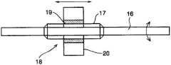
图3是该换档轴和换档键的主视图。Fig. 3 is a front view of the shift shaft and shift key.
图4是用于说明行星架的构造的纵向截面立体图。Fig. 4 is a longitudinal sectional perspective view for explaining the structure of the carrier.
图5是用于说明凸轮机构的一例的局部结构图。Fig. 5 is a partial configuration diagram illustrating an example of a cam mechanism.
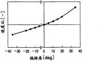
图6是表示偏转角度和变速比(速度比)的关系的线图。FIG. 6 is a graph showing the relationship between the yaw angle and the gear ratio (speed ratio).
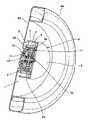
图7是表示作为轮内电动机使用的例子的纵向截面立体图。Fig. 7 is a longitudinal sectional perspective view showing an example of use as an in-wheel motor.
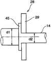
图8是表示定子轴的构造的其他例子的局部图。Fig. 8 is a partial view showing another example of the structure of the stator shaft.
具体实施方式Detailed ways
接着,对本发明进行更具体地说明。图1和图2是表示本发明涉及的电动机1的一例,此处所示的电动机1构成为在电动机部2的内周部配置无级变速机构3。当对该电动机部2的结构进行说明时,电动机部2具备定子线圈4和配置在该定子线圈4的内周侧的转子5。定子线圈4是将卷绕于铁心的多个线圈圆筒状配置而构成的,被固定在外壳体6的圆筒部7的内周面。外壳体6是具有底部的圆筒状的部件,相对于其底部的板状部分是端板部8,圆筒部7与该圆板状的端板部8的外周部一体化。Next, the present invention will be described more specifically. 1 and 2 show an example of a
转子5是圆筒状的部件,在其外周部安装有多个永磁铁(未图示)。因而,电动机部2构成为永磁铁式同步电动机。该转子5设定成与上述圆筒部7大致相同的长度,因而,转子5被收纳在外壳体6的内部。在转子5的轴线方向的两端部设置有向内周侧(中心侧)延伸的凸缘部9、10。上述端板部8侧的凸缘部9相对短,与此相对,与其相反一侧即外壳体6的开口端侧的凸缘部10形成为相对长,轴承11、12与各个凸缘部9、10的内周部嵌合。即,转子5被这些轴承11、12支承为能够旋转。另外,一个轴承11与形成于上述端板部8的内面的凸部的外周面嵌合,而另一个轴承12与后述的输出轴13的外周面嵌合。The
接着对无级变速机构3进行说明。在上述端板部8的中心部设置有定子轴14,该定子轴14是贯通外壳体6而沿着与端板部8相反侧延伸的固定轴。该定子轴14与上述圆筒部7的中心轴线一致地配置,其一端部与端板部8一体化。能够适当地选择用于使定子轴14与端板部8一体化的方法,例如也可以是热压配合、焊接、螺纹固定等的任一个。从定子轴14中的端板部8侧的端部到超过轴线方向的中间部的程度的位置形成为中空。此外,在定子轴14的轴线方向的中间部形成有预定长度的两个狭缝15。上述狭缝15形成在相对于定子轴14的中心轴线呈对称的位置,从定子轴14的外面贯通至中空部。Next, the continuously
进而,在形成于定子轴14的中心部的中空部插入换档轴16,该换档轴16被旋转自如地支承于该中空部。该换档轴16的一端部从定子轴14的上述端板部8侧的端部突出,而换档轴16的中间部、更准确地说,在与上述狭缝15对应的部位形成有外螺纹部17,换档键18与该外螺纹部17螺纹接合。在图3中示意地表示换档轴16和换档键18。该换档键18是具有与上述外螺纹部17螺纹接合的圆筒状的内螺纹部19和从该内螺纹部19沿着直径方向突出的两个键部20,该键部20贯通上述狭缝15而向定子轴14的外周侧突出。即,通过使换档键18旋转,换档键18的键部20沿着定子轴14的轴线方向前后运动。Furthermore, a
进而,轴承部件21以能够沿着轴线方向前后运动的方式松弛地嵌合于定子轴14的外周部。该轴承部件21,其轴线方向的中间部遍及全周形成为凹陷的形状,且从整体上看是环状的部件,在直径方向对称的两个部位嵌合有上述键部20的前端部。因而,轴承部件21构成为通过键部20沿着轴线方向移动。Furthermore, the bearing
轴承部件21的凹陷部中的接近底部的部位形成为截面圆弧状的光滑的凹曲面,该凹曲面成为配置轴承滚珠22的轴承面。而且,被该轴承滚珠22支承为旋转自如的空转滚柱23配置在轴承部件21的中央部。该空转滚柱23是圆筒状的部件,通过使内周面的左右两侧的部分与上述轴承滚珠22接触,被轴承滚珠22以及轴承部件21支承为旋转自如。因而,该空转滚柱23构成为与轴承部件21一起沿着轴线方向前后运动。A portion near the bottom of the recessed portion of the bearing
在上述空转滚柱23的外周侧配置有相当于本发明的转动体的多个行星球24。该行星球24能够利用磁性体或非磁性体的任一个而构成,优选其形状是完全的球形,但除此之外也可以是像橄榄球那样的截面为椭圆形状等且外周面光滑的曲面的行星球。在图2中示出8个行星球24,但上述各行星球24实际上彼此不接触。优选空出预定的间隙以在各行星球24旋转的情况下在各个行星球24之间不产生拖曳扭矩。A plurality of
各行星球24被穿过贯通其中心的支承轴25支承为旋转自如。例如,在支承轴25的外周面和行星球24之间配置有轴承,利用该轴承能够使行星球24旋转。上述支承轴25,如图1所示,朝向与上述定子轴14平行的方向配置,更具体而言,位于包含定子轴14的中心轴线的平面内,且在该平面内在与定子轴14平行的状态以及从该平行状态倾斜的状态之间摆动(偏转)。Each
支承轴25的两端部从行星球24突出,在该突出的端部安装有偏转用臂部26。该偏转用臂部26用于对支承轴25和被该支承轴25支承的行星球24施加偏转力,在图示的例子中,各偏转用臂部26从支承轴25朝向定子轴14、即在半径方向朝向中心侧延伸,各个前端部(即旋转中心侧的端部)逐渐变细。而且,安装于各支承轴25的左右的偏转用臂部26与支承部件21的左右的侧面(外表面)接触以夹持上述轴承部件21。即,各偏转用臂部26的前端部的内侧的侧面成为定子轴14侧向外开的倾斜面,相对于此,轴承部件21的外侧面形成于凸曲面27。因而,构成为各偏转用臂部26与支承部件21点接触或者线接触。轴承部件21沿轴线方向移动所引起的负载,作为朝向定子轴14的倾斜外侧的力作用于像这样偏转用臂部26的倾斜面与轴承部件21的凸曲面27的接触部位。因此,通过轴承部件21沿着轴线方向前后运动,支承轴25和被该支承轴25支承的行星球24的旋转中心轴线在通过定子轴14的旋转中心轴线的平面内倾斜。Both end portions of the
上述行星球24、贯通该行星球的中心部的支承轴25以及各偏转用臂部26,被保持为不在定子轴14的轴线方向移动。设置有用于进行该保持的行星架28。该行星架28,如图1和图4所示,是通过多根连结轴30连结左右一对圆板部29而构成的框状部件,在各个圆板部29的相互对置的面,与上述偏转用臂部26大致相同的宽度且与偏转用臂部26的数量相同的放射槽31从中心部形成至外周缘。而且,在这些放射槽31的内部配置有各偏转用臂部26,该偏转用臂部26能够进行上述偏转动作。因而,偏转用臂部26、安装有该偏转用臂部26的支承轴25以及被支承轴25支承的行星球24,不围绕定子轴14旋转(公转)。The above-mentioned
通过如上述那样将行星架28构成为框状,在其外周侧开放,因而各行星球24向行星架28的外周侧稍微突出。在像这样向行星架28的外周侧突出的各行星球24的外周面设置有两个作为旋转体的输入圆盘32和输出圆盘33,该输入圆盘32和输出圆盘33以能够传递扭矩的方式与上述各行星球24的外周面接触。上述输入圆盘32和输出圆盘33是从整体上看呈环状的部件,隔着行星球24而配置在图1的左右两侧。而且,上述输入圆盘32和输出圆盘33通过与行星球24的外周面相同曲率的凹圆弧面与行星球24的外周面接触。Since the
输入圆盘32具有比上述转子5的内径稍小的外径,输入圆盘32和与转子5一体的相对短的凸缘部9对置配置。而且,在该凸缘部9和输入圆盘32的背面之间设置有凸轮机构34。此外,输出圆盘33相当于本发明中的输出部件,隔着行星球24配置在与输入圆盘32相反一侧。而且,在输出圆盘33的背面侧配置有凸轮机构35,该输出圆盘33经由该凸轮机构35与输出轴13连结。The
即,输出轴13为中空轴且两个轴承36与上述定子轴14的外周侧嵌合,且被支承为旋转自如。该输出轴13的一个端部向外壳体6的外侧突出,与此相对,在位于外壳体6的内部的另一个端部一体地形成有在半径方向向外侧延伸的凸缘部37。该凸缘部37的外径是比转子5的内径稍小,且与上述输入圆盘32、输出圆盘33大致相同的外径。在该凸缘部37的外周部设置有圆筒部,该圆筒部通过上述行星架28的外周侧朝向输出圆盘33延伸,在该圆筒部的前端面和外部圆盘33的背面之间配置有凸轮机构35。That is, the
在此,对凸轮机构34、35进行说明,上述凸轮机构34、35是用于基于扭矩产生轴线方向的推力的机构,如果示出其原理结构则如图5所示。即,相互传递扭矩的第一旋转部件38和第二旋转部件39在同一轴线上对置配置,在上述旋转部件38、39的相互对置的面的至少一方形成有凸轮面40,该凸轮面40以上述旋转部件38、39的间隔逐渐变窄的方式朝向圆周方向倾斜。换言之,至少一方的旋转部件的厚度在圆周方向逐渐变厚。而且,在这些相互的间隔在圆周方向逐渐变化的各旋转部件38、39之间夹入凸轮滚珠41。Here, the
因而,当夹入凸轮滚珠41的部位的间隔变窄方向的扭矩作用于各旋转部件38、39之间时,各旋转部件38、39夹持凸轮滚珠41而相互一体化,并且与扭矩和凸轮面40的偏转角度对应地产生轴线方向的推力。对此进行简单说明,当将输入扭矩设为Tin、将凸轮滚珠41的个数设为n、将设置有凸轮滚珠41的部位的各旋转部件38、39的半径设为r时,夹持凸轮滚珠41的部位的圆周方向(切线方向)的负载Ft为Therefore, when a torque in the direction in which the distance between the positions sandwiched by the
Ft=Tin/(n·r) ……(1)Ft=Tin/(n·r) ……(1)
而且,当将凸轮面40的偏转角度(参照图5)设为α时,沿轴线方向作用的推力Fa为,Furthermore, when the deflection angle (see FIG. 5 ) of the
Fa=Ft/tan(α/2) ……(2)Fa=Ft/tan(α/2)……(2)
当预定的扭矩作用于转子5时,该扭矩经由凸轮机构34传递至输入圆盘32,同时产生与该扭矩对应的轴线方向的推力,利用该推力将输入圆盘32向行星球24按压。此外,当扭矩作用于与行星球24接触的输出圆盘33时,该扭矩经由凸轮机构34传递至输出轴13,与此同时,产生与该扭矩对应的轴线方向推力,利用该推力将输出圆盘33向行星架24按压。这样,与传递的扭矩对应地将各圆盘32、33向行星架24按压,与该推力和摩擦系数对应地设定传递扭矩容量。另外,在输出轴13的凸缘部37与转子5的凸缘部10之间配置有推力轴承42。When a predetermined torque acts on the
上述结构的电动机1,通过使被控制的交流电流在定子线圈4中流动,使转子5产生扭矩。由于转子5被轴承11、12支承为旋转自如,所以通过扭矩作用而旋转。在该情况下,由于在相对短的凸缘部(图1中右侧的凸缘部)9和输入圆盘32之间设置有凸轮机构34,所以转子5和输入圆盘32通过凸轮机构34以能够一起一体旋转的方式连结,产生与转子5的扭矩对应的轴线方向的推力从而将输入圆盘32向行星球24按压。The
结果,利用输入圆盘32和行星架24之间的摩擦力从输入圆盘32对行星架24传递扭矩。由于行星球24被贯通其中心的支承轴25和空转滚柱23支承为旋转自如,所以通过从输入圆盘32传递来的扭矩而自转。另外,在该情况下,空转滚柱23也旋转。由于输出圆盘33也与行星球24接触,所以利用行星球24和输出圆盘33之间的摩擦力从行星球24向输出圆盘33传递扭矩。As a result, torque is transmitted from the
由于在该输出圆盘33和输出轴13的凸缘部37之间设置有上述的凸轮机构35,所以输出圆盘33和输出轴13通过凸轮机构35能够一起一体旋转的方式连结,产生与输出圆盘33的扭矩对应的轴线方向的推力,从而将输出圆盘33朝向行星球24按压,确保与该接触压力对应的传递扭矩容量。这样,转子5的扭矩经由无级变速机构3传递至输出轴13,从该输出轴13对外部预定的设备输出扭矩。Since the above-mentioned
如上述那样从转子5向输出轴13传递的扭矩,成为与无级变速机构3的传递扭矩容量对应的扭矩,该传递扭矩容量主要取决于行星球24与输入圆盘32以及行星球24与输出圆盘33之间的接触压力。因而,在由磁性体构成上述行星球24的情况下,由设置于转子5的永磁铁产生的吸引力作用于行星球24,利用该磁性吸引力将行星球24朝向输入圆盘32和输出圆盘33按压,因此能够使该接触压力增大,并能够使无级变速机构3的传递扭矩容量增大。与此相反,在由非磁性体构成行星球24的情况下,虽然对行星球24不作用磁性吸引力,但是通过隔开一定间隔配置行星球24和永磁铁,能够避免因两者的间隔间歇地变化所引起的齿槽扭矩。The torque transmitted from the
输出轴13所呈现的扭矩,成为与基于无级变速机构3的变速比对转子5的扭矩进行增减的扭矩。该无级变速机构3的变速比是与行星球24随同支承轴25一起偏转的偏转角度对应的变速比。即,在输入圆盘32和输出圆盘33的半径相同的情况下,如果支承轴25与定子轴14平行,则输入圆盘32所接触的部位的行星球24的旋转半径(距行星球24的旋转中心的半径)和输出圆盘33所接触的部位的行星球24的旋转半径(距行星球24的旋转中心的半径相同,因而变速比成为“1”。The torque exhibited by the
当与此对应支承轴25偏转时,输入圆盘32所接触的部位的行星球24的旋转半径和输出圆盘33所接触的部位的行星球24的旋转半径的任一方与偏转角度对应地增大,且另一方与偏转角度对应地减少。结果,相对于输入圆盘32的转速的输出圆盘33的转速,与上述旋转半径的变化对应地变化,结果,这些转速的比率亦即变速比与偏转角度对应地变化。在图6中用线图表示该状态。另外,在图6中,针对每个偏转角度分配将输入圆盘32的转速设为“1”时的输出圆盘33的转速,并用线将各点连结起来。When the supporting
如上述那样使行星球24与其支承轴25一起偏转的操作,是通过未图示的电动机、联杆机构等的换档装置使上述换档轴16旋转而进行的。即,当换档轴16旋转时,与其外螺纹部17螺纹接合的换档键18借助螺纹的作用沿着轴线方向移动。由于该换档键18与轴承部件21卡合,所以轴承部件21与换档键18一起沿着轴线方向移动。该轴承部件21的左右侧面成为凸曲面27,偏转用臂部26与该凹凸面27点接触或者线接触且该偏转用臂部26被支承为不沿着轴线方向移动地倾斜,因此通过轴承部件21沿着轴线方向移动而按压偏转用臂部26,利用在该倾斜面和凸曲面27的接触部产生的朝向斜外侧的力使偏转用臂部26倾斜。即,支承轴25以及被该支承轴25支承为旋转自如的行星球24,与偏转用臂部26一起倾斜,从而设定与该偏转角度对应的变速比。The operation of deflecting the
如上所述,本发明涉及的电动机1,能够将在转子5产生的扭矩与能使该扭矩无级(连续地)变化的变速比对应地进行增减并从输出轴13输出。此外,在将输出轴13的转速设为一定的情况下,能够与无级变速机构3的变速比对应地适当设定转子5的转速。因此,根据本发明涉及的电动机1,能够将转子5的转速设定成从特性线图等求出的能量效率良好的转速。此外,能够作成如下结构:通过电流流动而产生扭矩的电动机部2以及能够使增减该扭矩的变速比呈无级变化的无级变速机构3配置在同心圆上,能够收纳在单一的外壳体6的内部,因此能够容易地使作为整体的结构紧凑化。As described above, the
本发明涉及的电动机1,能够产生上述优点而用于各种用途。例如,能够作为车辆的轮内电动机加以使用,在图7中示意地表示其一例。在图7中符号43表示车辆的车轮,在该车轮43上装配有轮胎44。此外,在车轮43的中心部形成有贯通孔,通过使上述输出轴13与该贯通孔嵌合,将车轮43安装于电动机1的输出轴13。另一方面,该电动机1固定于未图示的车体。具体而言,通过将上述外壳体6中的端板部8与车体的适当部位接合,将电动机1安装于车体。通过采用这样的结构,能够扩大相对车体的接合面积,因此能够增大电动机1相对车体的固定强度。The
上述电动机1,外壳体6的轴线方向的一端侧被端板部8关闭,输出轴13朝向与此相反侧突出,因此通过从输出轴13输出扭矩而向输出轴13、从内周侧支承该输出轴13的定子轴14作用弯曲负载和剪切负载。为了作成对这样的负载充分耐受的构造,优选将定子轴14作成例如图8所示的构造。该图8所示的定子轴14,从行星架28突出的部分的外径d1设定成比固定于外壳体6的端部侧的外径d2大。此外,在该大径侧的部分形成有与行星架28的侧面密合的凸缘45。因而,如果作成图8所示的构造,则定子轴14中从行星架28突出而承受弯曲负载的部分的外径大,其刚性变高,因此能够提高定子轴14的支承刚性。The above-mentioned
另外,本发明并不限定于上述具体例,电动机部也可以是同步电动机以外的构造。此外,在上述具体例中,将与由空转滚柱支承的行星球接触的一个圆盘设为输入部件,将另一个圆盘设为输出部件,但上述无级变速机构由于是具备空转滚柱和两个圆盘的合计三个旋转元件的所谓的三元件的变速机构,所以也可以将三个旋转元件中的任意一个设为惰轮,且将另外两个旋转要素中的一个设为输入元件,将另外任意一个设为输出元件。进而,在作成使转动体受到磁性吸引力的情况下,也可以代替由磁性体构成转动体本身,而作成仅将转动体的外周部由磁性材料构成等、在一部分具备磁性体的结构。In addition, this invention is not limited to the said specific example, The motor part may have structures other than a synchronous motor. In addition, in the above-mentioned specific example, one disk contacting the planetary ball supported by the idler roller is used as the input member, and the other disk is used as the output member. A so-called three-element transmission mechanism with a total of three rotating elements and two disks, so any one of the three rotating elements can be used as an idler, and one of the other two rotating elements can be used as an input component, and set any other one as an output component. Furthermore, when the rotating body is subjected to magnetic attraction force, instead of constituting the rotating body itself with a magnetic body, only the outer peripheral portion of the rotating body is made of a magnetic material and partially equipped with a magnetic body.
Claims (8)
Applications Claiming Priority (1)
| Application Number | Priority Date | Filing Date | Title |
|---|---|---|---|
| PCT/JP2009/057885WO2010122634A1 (en) | 2009-04-21 | 2009-04-21 | Motor with transmission function |
Publications (1)
| Publication Number | Publication Date |
|---|---|
| CN102308459Atrue CN102308459A (en) | 2012-01-04 |
Family
ID=43010772
Family Applications (1)
| Application Number | Title | Priority Date | Filing Date |
|---|---|---|---|
| CN2009801251061APendingCN102308459A (en) | 2009-04-21 | 2009-04-21 | Motor with transmission function |
Country Status (5)
| Country | Link |
|---|---|
| US (1) | US20120025644A1 (en) |
| EP (1) | EP2424081A4 (en) |
| JP (1) | JP5263388B2 (en) |
| CN (1) | CN102308459A (en) |
| WO (1) | WO2010122634A1 (en) |
Cited By (3)
| Publication number | Priority date | Publication date | Assignee | Title |
|---|---|---|---|---|
| CN105465305A (en)* | 2014-09-30 | 2016-04-06 | 日本电产新宝株式会社 | Friction-type stepless transmission |
| CN107532949A (en)* | 2015-04-14 | 2018-01-02 | 舍弗勒技术股份两合公司 | Hollow mechanical part and device for measuring force or torque |
| CN112436622A (en)* | 2019-08-26 | 2021-03-02 | 东芝三菱电机产业系统株式会社 | Stator torque transmission structure, assembling/disassembling method thereof, disassembling jig for stator torque transmission structure, and motor drive system |
Families Citing this family (18)
| Publication number | Priority date | Publication date | Assignee | Title |
|---|---|---|---|---|
| JP2011030307A (en)* | 2009-07-22 | 2011-02-10 | Toyota Motor Corp | Rotary electric machine |
| CN102144113B (en) | 2009-12-02 | 2014-02-05 | 丰田自动车株式会社 | Stepless transmission |
| US8784261B2 (en) | 2009-12-02 | 2014-07-22 | Toyota Jidosha Kabushiki Kaisha | Continuously variable transmission |
| JP5316691B2 (en) | 2010-02-22 | 2013-10-16 | トヨタ自動車株式会社 | Power transmission device |
| WO2015161886A1 (en)* | 2014-04-24 | 2015-10-29 | Aktiebolaget Skf | Two-wheeled electrically assisted vehicle |
| TWI530066B (en)* | 2014-12-02 | 2016-04-11 | Prec Machinery Res &Development Ct | Hollow motor module |
| JP2016127747A (en)* | 2015-01-07 | 2016-07-11 | 財團法人精密機械研究發展中心 | Hollow motor module |
| JP6604820B2 (en)* | 2015-08-07 | 2019-11-13 | 日本電産サンキョー株式会社 | Planetary gear reducer and drive mechanism |
| FR3040926B1 (en)* | 2015-09-10 | 2018-05-18 | Lyptech | TRACTION CHAIN FOR A VEHICLE AND METHOD FOR MANAGING SUCH A CHAIN |
| JP6706483B2 (en)* | 2015-11-09 | 2020-06-10 | 株式会社デンソー | Geared motor and method of manufacturing geared motor |
| DE102016200265A1 (en)* | 2016-01-13 | 2017-07-13 | Robert Bosch Gmbh | Drive arrangement and motor-driven vehicle |
| RU2658226C2 (en)* | 2016-11-22 | 2018-06-19 | Равиль Гафиевич Хадеев | Automatic transmission inside wheel |
| JP6514248B2 (en)* | 2017-02-17 | 2019-05-15 | 本田技研工業株式会社 | Substructure of car body |
| JP6790947B2 (en)* | 2017-03-21 | 2020-11-25 | トヨタ自動車株式会社 | In-wheel motor unit |
| RU2680230C1 (en)* | 2017-12-29 | 2019-02-18 | Равиль Гафиевич Хадеев | Device for managing the pressure of liquid |
| US11408495B2 (en) | 2020-02-29 | 2022-08-09 | Schaeffler Technologies AG & Co. KG | Compact torque converter assembly for hybrid module |
| CN113883243A (en)* | 2020-07-02 | 2022-01-04 | 四川大学 | Self-adaptive variable-speed outer cone disc type non-spinning traction type continuously variable transmission |
| CN118061772B (en)* | 2024-04-24 | 2024-06-21 | 常州中云传动科技有限公司 | Rear axle driving structure capable of changing speed |
Citations (6)
| Publication number | Priority date | Publication date | Assignee | Title |
|---|---|---|---|---|
| US5513719A (en)* | 1993-05-24 | 1996-05-07 | Kabushikikaisha Equos Research | Hybrid vehicle |
| CN1281540A (en)* | 1997-10-22 | 2001-01-24 | 线形自行车公司 | Continuously variable transmission |
| JP2003070207A (en)* | 2001-08-24 | 2003-03-07 | Honda Motor Co Ltd | Power transmission device for hybrid vehicle |
| CN1866686A (en)* | 2005-04-27 | 2006-11-22 | 阿文梅里特尔技术有限责任公司 | Driveline motor with planetary gear system |
| WO2007116541A1 (en)* | 2006-03-31 | 2007-10-18 | Honda Motor Co., Ltd. | Wheel rotating device for in-wheel motor vehicle |
| JP2008196584A (en)* | 2007-02-13 | 2008-08-28 | Nippon Densan Corp | Load sensitive motor |
Family Cites Families (9)
| Publication number | Priority date | Publication date | Assignee | Title |
|---|---|---|---|---|
| JPS62101965A (en)* | 1985-10-25 | 1987-05-12 | Matsushita Electric Works Ltd | Differential planet roller reduction gear |
| US5508574A (en)* | 1994-11-23 | 1996-04-16 | Vlock; Alexander | Vehicle transmission system with variable speed drive |
| JPH1089435A (en)* | 1996-09-11 | 1998-04-07 | Mamoru Ishikuri | Continuously variable transmission |
| JP2001112215A (en)* | 1999-10-05 | 2001-04-20 | Yaskawa Electric Corp | Reducer integrated actuator |
| JP2004312845A (en)* | 2003-04-04 | 2004-11-04 | Nissan Motor Co Ltd | Stator for motor |
| WO2006041718A2 (en)* | 2004-10-05 | 2006-04-20 | Fallbrook Technologies, Inc. | Continuously variable transmission |
| PL1954959T3 (en)* | 2005-11-22 | 2013-10-31 | Fallbrook Ip Co Llc | Continuously variable transmission |
| US7936076B2 (en)* | 2007-01-22 | 2011-05-03 | Ut-Battelle, Llc | Utilization of rotor kinetic energy storage for hybrid vehicles |
| EP2142826B1 (en)* | 2007-04-24 | 2015-10-28 | Fallbrook Intellectual Property Company LLC | Electric traction drives |
- 2009
- 2009-04-21USUS13/001,680patent/US20120025644A1/ennot_activeAbandoned
- 2009-04-21CNCN2009801251061Apatent/CN102308459A/enactivePending
- 2009-04-21EPEP09843634.8Apatent/EP2424081A4/ennot_activeWithdrawn
- 2009-04-21WOPCT/JP2009/057885patent/WO2010122634A1/ennot_activeCeased
- 2009-04-21JPJP2011510111Apatent/JP5263388B2/enactiveActive
Patent Citations (6)
| Publication number | Priority date | Publication date | Assignee | Title |
|---|---|---|---|---|
| US5513719A (en)* | 1993-05-24 | 1996-05-07 | Kabushikikaisha Equos Research | Hybrid vehicle |
| CN1281540A (en)* | 1997-10-22 | 2001-01-24 | 线形自行车公司 | Continuously variable transmission |
| JP2003070207A (en)* | 2001-08-24 | 2003-03-07 | Honda Motor Co Ltd | Power transmission device for hybrid vehicle |
| CN1866686A (en)* | 2005-04-27 | 2006-11-22 | 阿文梅里特尔技术有限责任公司 | Driveline motor with planetary gear system |
| WO2007116541A1 (en)* | 2006-03-31 | 2007-10-18 | Honda Motor Co., Ltd. | Wheel rotating device for in-wheel motor vehicle |
| JP2008196584A (en)* | 2007-02-13 | 2008-08-28 | Nippon Densan Corp | Load sensitive motor |
Cited By (6)
| Publication number | Priority date | Publication date | Assignee | Title |
|---|---|---|---|---|
| CN105465305A (en)* | 2014-09-30 | 2016-04-06 | 日本电产新宝株式会社 | Friction-type stepless transmission |
| CN105465305B (en)* | 2014-09-30 | 2018-05-18 | 日本电产新宝株式会社 | Friction type stepless speed changer |
| CN107532949A (en)* | 2015-04-14 | 2018-01-02 | 舍弗勒技术股份两合公司 | Hollow mechanical part and device for measuring force or torque |
| CN107532949B (en)* | 2015-04-14 | 2020-02-11 | 舍弗勒技术股份两合公司 | Hollow mechanical part and device for measuring force or torque |
| CN112436622A (en)* | 2019-08-26 | 2021-03-02 | 东芝三菱电机产业系统株式会社 | Stator torque transmission structure, assembling/disassembling method thereof, disassembling jig for stator torque transmission structure, and motor drive system |
| CN112436622B (en)* | 2019-08-26 | 2024-10-18 | 株式会社Tmeic | Stator torque transmission structure, assembling/disassembling method thereof, disassembling jig for stator torque transmission structure, and motor driving system |
Also Published As
| Publication number | Publication date |
|---|---|
| EP2424081A4 (en) | 2013-11-13 |
| EP2424081A1 (en) | 2012-02-29 |
| US20120025644A1 (en) | 2012-02-02 |
| JPWO2010122634A1 (en) | 2012-10-22 |
| WO2010122634A1 (en) | 2010-10-28 |
| JP5263388B2 (en) | 2013-08-14 |
Similar Documents
| Publication | Publication Date | Title |
|---|---|---|
| JP5263388B2 (en) | Electric motor with speed change function | |
| JP5246346B2 (en) | Continuously variable transmission | |
| CN102265063B (en) | Continuously variable transmission | |
| JP5131354B2 (en) | Continuously variable transmission | |
| JP2015227691A (en) | Continuously variable transmission | |
| JPWO2013042226A1 (en) | Continuously variable transmission | |
| JP2012122568A (en) | Continuously variable transmission | |
| JP2012107725A (en) | Continuously variable transmission | |
| KR101047224B1 (en) | Continuously variable transmission | |
| JP2018118546A (en) | vehicle | |
| JP5803878B2 (en) | Continuously variable transmission | |
| JP4807318B2 (en) | Power transmission device | |
| JP5432408B1 (en) | A transmission suitable for using a plurality of large-diameter thin rotary electric machines that rotate in reverse to each other as a drive motor for an electric vehicle. | |
| JP3568919B2 (en) | Transmission | |
| EP0204625B1 (en) | Coupling mechanism for transmission between a driving and a driven shaft | |
| JP2021014868A (en) | Roller type differential speed reducer | |
| JP2014214838A (en) | Continuously variable transmission | |
| JP2005265089A (en) | Friction type transmission | |
| JP2009030685A (en) | Planetary roller mechanism | |
| JP4978412B2 (en) | Planetary roller mechanism | |
| JP2014077467A (en) | Continuously variable transmission | |
| JP2005221059A (en) | Continuously variable transmission | |
| JP2019060370A (en) | Continuously variable transmission mechanism | |
| JPH06241292A (en) | Magneto ball planetary gear transmission | |
| JPH0681918A (en) | Magnetic ball planetary deceleration device |
Legal Events
| Date | Code | Title | Description |
|---|---|---|---|
| C06 | Publication | ||
| PB01 | Publication | ||
| C10 | Entry into substantive examination | ||
| SE01 | Entry into force of request for substantive examination | ||
| C02 | Deemed withdrawal of patent application after publication (patent law 2001) | ||
| WD01 | Invention patent application deemed withdrawn after publication | Application publication date:20120104 |