CN102308057B - Offset Stochastic control - Google Patents
Offset Stochastic controlDownload PDFInfo
- Publication number
- CN102308057B CN102308057BCN200980156389.6ACN200980156389ACN102308057BCN 102308057 BCN102308057 BCN 102308057BCN 200980156389 ACN200980156389 ACN 200980156389ACN 102308057 BCN102308057 BCN 102308057B
- Authority
- CN
- China
- Prior art keywords
- borehole
- drilling
- drilling system
- interaction
- controlling
- Prior art date
- Legal status (The legal status is an assumption and is not a legal conclusion. Google has not performed a legal analysis and makes no representation as to the accuracy of the status listed.)
- Expired - Fee Related
Links
- 238000005553drillingMethods0.000claimsabstractdescription563
- 230000003993interactionEffects0.000claimsabstractdescription258
- 238000000034methodMethods0.000claimsabstractdescription136
- 230000015572biosynthetic processEffects0.000claimsabstractdescription79
- 230000008846dynamic interplayEffects0.000claimsabstractdescription68
- 238000005520cutting processMethods0.000claimsdescription142
- 230000033001locomotionEffects0.000claimsdescription118
- 230000008569processEffects0.000claimsdescription87
- 230000002093peripheral effectEffects0.000claimsdescription37
- 230000008859changeEffects0.000claimsdescription18
- 230000007246mechanismEffects0.000claimsdescription12
- 230000001747exhibiting effectEffects0.000claimsdescription5
- 238000005755formation reactionMethods0.000description73
- 230000001965increasing effectEffects0.000description26
- 239000003381stabilizerSubstances0.000description15
- 239000012530fluidSubstances0.000description13
- 230000002401inhibitory effectEffects0.000description12
- 230000002829reductive effectEffects0.000description12
- 230000000694effectsEffects0.000description9
- 230000006870functionEffects0.000description9
- 230000004044responseEffects0.000description9
- 239000011435rockSubstances0.000description9
- 238000013461designMethods0.000description8
- 238000007373indentationMethods0.000description8
- 230000003247decreasing effectEffects0.000description7
- 230000003252repetitive effectEffects0.000description7
- 238000007493shaping processMethods0.000description7
- 230000009471actionEffects0.000description6
- 238000004458analytical methodMethods0.000description6
- 238000005452bendingMethods0.000description6
- 230000005764inhibitory processEffects0.000description6
- 238000012360testing methodMethods0.000description6
- 238000006243chemical reactionMethods0.000description4
- 230000008878couplingEffects0.000description4
- 238000010168coupling processMethods0.000description4
- 238000005859coupling reactionMethods0.000description4
- 238000010586diagramMethods0.000description4
- 210000002310elbow jointAnatomy0.000description4
- 210000001503jointAnatomy0.000description4
- 230000001052transient effectEffects0.000description4
- 230000000712assemblyEffects0.000description3
- 238000000429assemblyMethods0.000description3
- 238000006073displacement reactionMethods0.000description3
- 230000005484gravityEffects0.000description3
- 230000035515penetrationEffects0.000description3
- 239000004215Carbon black (E152)Substances0.000description2
- 230000006399behaviorEffects0.000description2
- 230000009286beneficial effectEffects0.000description2
- 238000000576coating methodMethods0.000description2
- 238000004891communicationMethods0.000description2
- 230000001627detrimental effectEffects0.000description2
- 229930195733hydrocarbonNatural products0.000description2
- 150000002430hydrocarbonsChemical class0.000description2
- 238000007689inspectionMethods0.000description2
- 230000001788irregularEffects0.000description2
- 238000012544monitoring processMethods0.000description2
- 230000010355oscillationEffects0.000description2
- 238000012545processingMethods0.000description2
- 239000013598vectorSubstances0.000description2
- XLYOFNOQVPJJNP-UHFFFAOYSA-NwaterSubstancesOXLYOFNOQVPJJNP-UHFFFAOYSA-N0.000description2
- 241001416181Axis axisSpecies0.000description1
- 230000001133accelerationEffects0.000description1
- 238000013459approachMethods0.000description1
- 230000008901benefitEffects0.000description1
- 238000010276constructionMethods0.000description1
- 230000001419dependent effectEffects0.000description1
- 239000013013elastic materialSubstances0.000description1
- 230000002708enhancing effectEffects0.000description1
- 230000007613environmental effectEffects0.000description1
- 239000000835fiberSubstances0.000description1
- 230000003116impacting effectEffects0.000description1
- 238000002347injectionMethods0.000description1
- 239000007924injectionSubstances0.000description1
- 230000000670limiting effectEffects0.000description1
- 238000012423maintenanceMethods0.000description1
- 239000000463materialSubstances0.000description1
- 238000005259measurementMethods0.000description1
- 239000002184metalSubstances0.000description1
- 238000012986modificationMethods0.000description1
- 230000004048modificationEffects0.000description1
- 210000002445nippleAnatomy0.000description1
- 238000010248power generationMethods0.000description1
- 230000000284resting effectEffects0.000description1
- 235000019592roughnessNutrition0.000description1
- 239000013049sedimentSubstances0.000description1
- 239000007787solidSubstances0.000description1
- 125000006850spacer groupChemical group0.000description1
- 239000000126substanceSubstances0.000description1
- 238000004441surface measurementMethods0.000description1
- 230000001360synchronised effectEffects0.000description1
Images


Classifications
- E—FIXED CONSTRUCTIONS
- E21—EARTH OR ROCK DRILLING; MINING
- E21B—EARTH OR ROCK DRILLING; OBTAINING OIL, GAS, WATER, SOLUBLE OR MELTABLE MATERIALS OR A SLURRY OF MINERALS FROM WELLS
- E21B7/00—Special methods or apparatus for drilling
- E21B7/04—Directional drilling
- E21B7/06—Deflecting the direction of boreholes
- E21B7/062—Deflecting the direction of boreholes the tool shaft rotating inside a non-rotating guide travelling with the shaft
- E—FIXED CONSTRUCTIONS
- E21—EARTH OR ROCK DRILLING; MINING
- E21B—EARTH OR ROCK DRILLING; OBTAINING OIL, GAS, WATER, SOLUBLE OR MELTABLE MATERIALS OR A SLURRY OF MINERALS FROM WELLS
- E21B17/00—Drilling rods or pipes; Flexible drill strings; Kellies; Drill collars; Sucker rods; Cables; Casings; Tubings
- E21B17/10—Wear protectors; Centralising devices, e.g. stabilisers
- E21B17/1092—Gauge section of drill bits
- E—FIXED CONSTRUCTIONS
- E21—EARTH OR ROCK DRILLING; MINING
- E21B—EARTH OR ROCK DRILLING; OBTAINING OIL, GAS, WATER, SOLUBLE OR MELTABLE MATERIALS OR A SLURRY OF MINERALS FROM WELLS
- E21B7/00—Special methods or apparatus for drilling
- E21B7/04—Directional drilling
- E21B7/06—Deflecting the direction of boreholes
- E21B7/068—Deflecting the direction of boreholes drilled by a down-hole drilling motor
Landscapes
- Engineering & Computer Science (AREA)
- Life Sciences & Earth Sciences (AREA)
- Geology (AREA)
- Mining & Mineral Resources (AREA)
- Physics & Mathematics (AREA)
- Environmental & Geological Engineering (AREA)
- Fluid Mechanics (AREA)
- General Life Sciences & Earth Sciences (AREA)
- Geochemistry & Mineralogy (AREA)
- Mechanical Engineering (AREA)
- Earth Drilling (AREA)
Abstract
Translated fromChineseDescription
Translated fromChinese技术领域technical field
本发明基本上涉及一种用于控制钻孔系统的方法和系统,该钻孔系统用于在地层中钻出钻孔。更具体地,而非限制性地,在本发明的一个实施例中,提供了一种系统和方法,用于控制用于钻出钻孔的钻孔系统与被钻孔系统钻出的钻孔的内表面之间的相互作用,从而用于钻孔系统的导向,使其定向地穿过地层钻出钻孔。在本发明的某些方面,钻孔系统可被控制,从而使得钻孔达到预定目标。The present invention generally relates to a method and system for controlling a drilling system for drilling a borehole in an earth formation. More specifically, without limitation, in one embodiment of the present invention, a system and method are provided for controlling a drilling system for drilling a borehole and a borehole drilled by the drilling system The interaction between the inner surfaces of the drilling system is used to guide the drilling system so that it drills the borehole directionally through the formation. In certain aspects of the invention, the drilling system can be controlled so that the borehole is drilled to a predetermined target.
在本发明的另一个实施例中,当钻孔系统钻出钻孔时与钻孔系统的功能相关的数据可以被检测到,并且用于钻出钻孔的钻孔系统与钻孔的内表面之间的相互作用可以响应检测到的数据被控制,从而提供用于控制钻孔系统的操作。在某些方面,钻孔系统与内表面之间的相互作用可以被控制,从而用于控制钻头与地层的相互作用。In another embodiment of the present invention, data related to the function of the drilling system can be detected when the drilling system drills the borehole, and the drilling system used to drill the borehole is associated with the inner surface of the borehole The interaction between may be controlled in response to the sensed data, thereby providing for controlling the operation of the drilling system. In certain aspects, the interaction between the drilling system and the interior surface can be controlled, thereby being used to control the interaction of the drill bit with the formation.
背景技术Background technique
在许多产业,通常期望定向地穿过地层钻出钻孔或者在地下地层中钻取岩芯,从而使得钻孔和/或取芯可以绕过和/或通过地层中的沉积物和/或贮藏物,以达到地层中的预定目标和/或类似物。当在地下地层中钻孔或取芯时,有时期望能够改变以及控制钻孔的方向,例如使钻孔指向期望的目标,或者一旦达到目标则在包含碳氢化合物的区域内部水平地控制方向。还期望到是当钻出直的钻孔时对与期望方向的偏离进行校正,或者控制钻孔方向以避免障碍物。In many industries, it is often desirable to drill boreholes or drill cores in subterranean formations directionally so that the borehole and/or coring can bypass and/or pass through sediments and/or deposits in the formation. objects to reach predetermined targets and/or the like in the formation. When drilling or coring a subterranean formation, it is sometimes desirable to be able to change and control the direction of the borehole, such as to point the borehole at a desired target, or horizontally within a hydrocarbon-containing zone once the target is reached. It is also desirable to correct for deviations from the desired direction when drilling a straight borehole, or to control the direction of the borehole to avoid obstructions.
在碳氢化合物产业中,钻孔可被钻出,从而在特定位置截取到特定的地下地层。在一些钻孔工艺中,为了钻出期望的钻孔,穿过地层的钻孔轨迹可被预先设计并且钻孔系统可被控制以与轨迹相符合。在其它工艺中、或者与先前工艺相结合,用于钻孔的目标可被确定下来并且在地层中钻出钻孔的工作可以在钻孔过程期间被监测并且可采取步骤来确保钻孔达到预定目标。此外,钻孔系统的操作可被控制,以提供用于经济的钻孔,其可包括尽可能快速地钻穿地层的钻孔、减小钻头磨损的钻孔、获得穿过地层最优钻孔和最优钻头磨损的钻孔、和/或类似的钻孔。In the hydrocarbon industry, boreholes may be drilled to intercept specific subterranean formations at specific locations. In some drilling processes, in order to drill a desired borehole, a borehole trajectory through the formation may be pre-planned and the drilling system may be controlled to conform to the trajectory. In other processes, or in combination with previous processes, targets for drilling can be determined and the work of drilling the borehole in the formation can be monitored during the drilling process and steps can be taken to ensure that the borehole achieves the intended Target. In addition, the operation of the drilling system can be controlled to provide for economical drilling, which can include drilling through the formation as quickly as possible, drilling with reduced drill bit wear, obtaining optimal drilling through the formation and optimal bit wear drilling, and/or similar drilling.
钻孔的一个方面被称为“定向钻孔”。定向钻孔是有意地使钻孔/井孔偏离它自然地采用的路径。换句话说,定向钻孔是使钻柱能够导向,从而使它能在期望方向上行进。One aspect of drilling is known as "directional drilling." Directional drilling is the intentional diversion of a borehole/wellbore from the path it naturally takes. In other words, directional drilling is the ability to steer the drill string so that it travels in the desired direction.
定向钻孔在离岸钻孔中是有利的,原因是它使得许多钻孔能够通过单个平台钻出。定向钻孔还能够进行穿过贮藏物的水平钻孔。水平钻孔使得井孔的更长长度横穿贮藏物,这会增加钻井的生产率。Directional drilling is advantageous in offshore drilling because it enables many boreholes to be drilled from a single platform. Directional drilling also enables horizontal drilling through storage. Horizontal drilling allows a longer length of the wellbore to traverse the reservoir, which increases the productivity of the well.
定向钻孔系统还能够用于在垂直钻孔操作中。通常钻头会偏离预定钻孔轨迹,原因是被刺穿的地层具有不可预知的特性或者钻头经受着变化的作用力。当这种偏离发生时,定向钻孔系统可用来使钻头在规定的过程中返回。Directional drilling systems can also be used in vertical drilling operations. Often the drill bit deviates from the intended drilling trajectory because of the unpredictable characteristics of the formation being penetrated or the varying forces experienced by the drill bit. When this deviation occurs, the directional drilling system can be used to return the drill bit on a prescribed course.
用于钻孔定向钻进的监测步骤可包括确定出钻头在地层中的位置、确定出钻头在地层中的方向、确定出钻孔系统的钻压、确定出穿过地层的钻进速度、确定出被钻进的地层的特性、确定出围绕着钻头的地下地层的特性、期望查明钻头前方地层的特性、地层的地震分析、确定出靠近钻头的贮藏物等的特性、测量钻孔中和/或钻孔周围的压力、温度和/或类似数值、和/或类似情况。在用于钻孔定向钻进的任意步骤中,无论是否沿循着预先设计的轨迹,监测钻孔工作和/或钻孔情况和/或类似情形都必须能够给钻孔系统导向。The monitoring steps for borehole directional drilling may include determining the position of the drill bit in the formation, determining the direction of the drill bit in the formation, determining the weight on bit of the drilling system, determining the rate of penetration through the formation, determining Characterize the formation being drilled, determine the characteristics of the subterranean formation surrounding the drill bit, expect to ascertain the characteristics of the formation ahead of the drill bit, seismic analysis of the formation, determine the characteristics of the reservoir near the drill bit, etc., measure the borehole and and/or pressure, temperature and/or the like around the borehole, and/or the like. In any step for directional drilling of a borehole, monitoring the drilling work and/or drilling conditions and/or the like must be able to steer the drilling system, whether following a pre-planned trajectory or not.
在钻孔操作期间作用在钻头上的作用力包括重力、钻头产生的转矩、施加到钻头的末端载荷、以及来自于钻孔组件的弯曲力矩。这些与被钻进地层的类型以及地层与钻孔的斜度相关的作用力在钻孔过程期间可形成复杂的、交互的作用力系统。The forces acting on the drill bit during drilling operations include gravity, torque generated by the drill bit, tip loads applied to the drill bit, and bending moments from the drilling assembly. These forces related to the type of formation being drilled and the inclination of the formation to the borehole can form a complex, interacting force system during the drilling process.
钻孔系统可包括“旋转钻进”系统,其中包括钻头的井底钻具连接到钻柱,该钻柱可以由钻井平台而驱动/旋转。在旋转钻进系统中,钻孔的定向钻孔可通过改变例如钻压、旋转速度等因素而提供。Drilling systems may include "rotary drilling" systems in which a bottom hole assembly including a drill bit is connected to a drill string that may be driven/rotated by a drilling platform. In rotary drilling systems, directional drilling of boreholes can be provided by varying factors such as weight on bit, rotational speed, etc.
对于旋转钻孔,已知的定向钻孔方法包括使用旋转导向系统(“RSS”)。在RSS中,钻柱从表面开始旋转,并且井下装置导致钻头在期望方向上钻进。旋转钻柱极大地降低了钻柱在钻进期间搁置或卡住的发生。For rotary drilling, known directional drilling methods include the use of a rotary steerable system ("RSS"). In RSS, the drill string is rotated from the surface, and downhole equipment causes the bit to drill in the desired direction. Rotating the drill string greatly reduces the occurrence of the drill string stalling or jamming during drilling.
用于在地层中钻出偏离钻孔的旋转导向钻孔系统可通常被分成“摆动钻头”系统或者“推靠钻头”系统。在摆动钻头系统中,钻头的旋转轴线与井底钻具(“BHA”)在新的钻孔通常方向上的局部轴线相偏离。钻孔根据由上下稳定器接触点及钻头限定的常规的三点几何形状而推进。与钻头和下稳定器之间有限距离相联系的钻头轴线偏离角度导致了对于产生弧线所需要的非共线情况。这可以通过多种方式实现,包括在井底钻具靠近下稳定器的位置的固定弯曲或者钻头驱动轴在上下稳定器之间分布的挠曲。Rotary steerable drilling systems used to drill off-bore holes in formations can generally be classified as "swing bit" systems or "push bit" systems. In an oscillating bit system, the rotational axis of the drill bit is offset from the local axis of the bottom hole assembly ("BHA") in the normal direction of the new borehole. The borehole advances according to a conventional three-point geometry defined by the upper and lower stabilizer contact points and the drill bit. The off-axis angle of the drill bit associated with the finite distance between the drill bit and the lower stabilizer results in the non-collinearity needed to create the arc. This can be accomplished in a number of ways, including fixed bending of the BHA near the lower stabilizer or distributed deflection of the bit drive shaft between the upper and lower stabilizers.
摆动钻头可包括使用井底马达来使钻头旋转,马达和钻头被固定到钻柱上,该钻柱包括成一定角度的弯曲。在这种系统中,钻头可通过铰链型或者倾斜机构/接头、弯接头或者类似物而连接到马达,其中钻头可相对于马达倾斜。当钻孔方向需要改变时,钻柱的旋转可以停止并且钻头可使用井底马达而被定位在钻孔中需要的方向上,并且钻头的旋转可开始在期望方向上的钻进。在这种设置中,钻孔方向依赖于钻柱的角度位置。Oscillating the drill bit may include using a downhole motor to rotate the drill bit, the motor and drill bit being secured to a drill string that includes angled bends. In such a system, the drill bit may be connected to the motor by a hinge type or tilting mechanism/joint, elbow joint or similar, wherein the drill bit may be tilted relative to the motor. When the drilling direction needs to be changed, the rotation of the drill string can be stopped and the drill bit can be positioned in the desired direction in the borehole using the downhole motor, and the rotation of the drill bit can begin drilling in the desired direction. In this setup, the drilling direction is dependent on the angular position of the drill string.
理想地,在摆动钻头系统中,钻头不需要斜向地切削,原因是钻头轴线在弯曲的钻孔方向上连续地旋转。摆动式旋转导向系统的示例以及它们如何操作在美国专利申请公开号No.2002/0011359;2001/0052428中以及美国专利No.6,394,193;6,364,034;6,244,361;6,158,529;6,092,610;以及5,113,953中进行了描述,所述内容全部通过参考而被结合在此。Ideally, in an oscillating bit system, the bit does not need to cut obliquely because the bit axis rotates continuously in the curved drilling direction. Examples of oscillating rotary steerable systems and how they operate are described in U.S. Patent Application Publication Nos. 2002/0011359; 2001/0052428 and in U.S. Patent Nos. 6,394,193; The foregoing is hereby incorporated by reference in its entirety.
推靠钻头系统以及使用与钻孔壁相抵抗的作用力来使钻柱弯曲和/或使钻头在预定方向上钻进。在推靠钻头旋转导向系统中,必要的非共线条件是通过使机构施加作用力或者在相对于钻孔推进方向而优先定向的方向上产生位移而获得。这可以通过多种方式实现,包括非旋转(相对于钻孔)、基于在期望导向方向上向钻头施加作用力的方法以及偏心致动器的位移。此外,导向通过在钻头与至少两个其它接触点之间形成非共线而获得。理想地,钻头需要侧向地切削,从而产生弯曲的孔。推靠钻头型旋转导向系统以及它们如何操作在美国专利No.5,265,682;5,553,678;5,803,185;6,089,332;5,695,015;5,685,379;5,706,905;5,553,679;5,673,763;5,520,255;5,603,385;5,582,259;5,778,992;5,971,085中进行了描述,所述内容全部通过参考而被结合在此。Pushing against the bit system and using the force against the borehole wall bends the drill string and/or drills the bit in a predetermined direction. In push-by-bit rotary steerable systems, the necessary non-collinear condition is achieved by having the mechanism apply force or displacement in a direction preferentially oriented relative to the direction of drilling advance. This can be achieved in a number of ways, including non-rotational (relative to the borehole), methods based on applying a force to the drill bit in the desired steering direction, and displacement of an eccentric actuator. Furthermore, steering is achieved by creating non-collinearity between the drill bit and at least two other contact points. Ideally, the drill bit needs to cut sideways, creating a curved hole.推靠钻头型旋转导向系统以及它们如何操作在美国专利No.5,265,682;5,553,678;5,803,185;6,089,332;5,695,015;5,685,379;5,706,905;5,553,679;5,673,763;5,520,255;5,603,385;5,582,259;5,778,992;5,971,085中进行了描述,所述The contents are hereby incorporated by reference in their entirety.
RSS的已知形式设置有“逆向旋转”机构,其在钻柱旋转的相反方向上旋转。通常地,逆向旋转的速度与钻柱旋转速度相同,从而使得逆向旋转部分相对于钻孔内部保持相同的角度位置。由于逆向旋转部分相对于钻孔不旋转,因此通常被本领域技术人员称为“对地静止”。在本公开中,术语“逆向旋转”与“对地静止”之间不做区别。Known forms of RSS are provided with a "counter-rotation" mechanism, which rotates in the opposite direction of drill string rotation. Typically, the counter-rotation is performed at the same speed as the drill string, so that the counter-rotation section maintains the same angular position relative to the borehole interior. Since the counter-rotating section does not rotate relative to the borehole, it is often referred to as "geostationary" by those skilled in the art. In this disclosure, no distinction is made between the terms "counter-rotating" and "geostationary".
推靠钻头系统通常使用内部或者外部逆向旋转稳定器。逆向旋转稳定器相对于钻孔壁保持固定角度(或者对地静止)。当钻孔偏离时,致动器在与期望偏离相反的方向上靠着钻孔壁挤压衬垫。这导致了钻头被推靠到期望方向。Push-by-bit systems typically use internal or external counter-rotation stabilizers. Counter-rotating stabilizers are held at a fixed angle (or geostationary) relative to the borehole wall. As the borehole deviates, the actuator compresses the pad against the borehole wall in a direction opposite to the desired deflection. This causes the drill bit to be pushed in the desired direction.
由致动器/衬垫所产生的作用力通过使井底钻具弯曲的作用力而平衡,以及所述作用力通过致动器/衬垫作用在井底钻具的相反侧面上,并且反作用力施加到钻头的切削器,由此使钻孔导向。在某些情况下,来自于衬垫/致动器的作用力足够大,以使得系统作用的地层变化。The force produced by the actuator/pad is balanced by the force bending the BHA, and the force acts through the actuator/pad on the opposite side of the BHA and reacts Force is applied to the cutter of the drill bit, thereby steering the drill hole. In some cases, the force from the pad/actuator is large enough to cause a change in the formation that the system acts on.
例如,斯伦贝谢旋转导向系统使用围绕着一段井底钻具设置的三个衬垫,从而与井底钻具同步地使用,从而在某个方向上推靠钻头以及使被钻进的钻孔导向。在该系统中,衬垫被安装成靠近钻头后方,在1-4英尺的范围内,并且被来自于循环流体的泥浆流所供给动力/致动。在其它系统中,由钻孔系统或楔形物或类似物所提供的钻压可被用于使钻孔系统在钻孔中定向。For example, the Schlumberger rotary steerable system uses three liners arranged around a length of BHA so that it is used in synchrony with the BHA to push against the bit in a certain direction and to move the drilled drill bit. hole guide. In this system, the liner is installed close to the rear of the drill bit, in the range of 1-4 feet, and is powered/actuated by the mud flow from the circulating fluid. In other systems, the weight on bit provided by the drilling system or a wedge or the like may be used to orient the drilling system in the borehole.
尽管用于靠着钻孔壁施加作用力以及利用反作用力在钻头的特定方向或位移上推靠钻头从而在期望方向上钻进的系统和方法可与包括旋转钻孔系统的钻孔系统共同使用,但是所述系统和方法具有缺点。例如,这种系统和方法需要在钻孔壁上施加大的作用力,从而使钻柱弯曲和/或使钻头在钻孔内定向;这种作用力可以是5kN或更大的量级,这需要形成大型/复杂的井下马达或者类似物。此外,由于井底钻具旋转产生反作用力来推靠钻头,因此许多系统和方法会反复地使用衬垫/致动器向外的推进力来进入到钻孔壁中,这会需要复杂/昂贵/高维护的同步系统,复杂的控制系统和/或类似系统。Although systems and methods for applying an action force against the borehole wall and utilizing a reaction force to push against a drill bit in a particular direction or displacement of the drill bit to drill in a desired direction can be used with drilling systems including rotary drilling systems , but the systems and methods have drawbacks. For example, such systems and methods require the application of large forces on the borehole wall to bend the drill string and/or orient the drill bit within the borehole; such forces may be on the order of 5 kN or greater, which A large/complex downhole motor or similar needs to be formed. Additionally, many systems and methods repeatedly use the pad/actuator's outward thrust into the borehole wall due to the counterforce generated by the rotation of the BHA to push against the drill bit, which can require complex/expensive/high Synchronization systems for maintenance, complex control systems and/or similar systems.
发明内容Contents of the invention
本公开基本上涉及一种用于控制钻孔系统的系统方法和,该钻孔系统被设置成用于穿过地下地层而钻出或者挖出钻孔。更具体地,而非限制性地,本发明的实施例提供用于通过钻孔噪音(即钻孔过程期间钻孔系统在钻孔内的不稳定运动)以及由于钻孔系统的不稳定运动所导致的钻孔系统与钻孔内表面之间的相互作用,来控制钻孔系统和/或钻孔过程。The present disclosure generally relates to a method and system for controlling a drilling system arranged to drill or excavate a borehole through a subterranean formation. More specifically, but without limitation, embodiments of the present invention provide a method for detecting noise through drilling noise (ie, erratic movement of the drilling system within the borehole during the drilling process) and The resulting interaction between the drilling system and the inner surface of the borehole to control the drilling system and/or the drilling process.
同时,本发明的实施例提供用于控制钻孔过程期间钻孔系统与钻孔内表面之间反复的相互作用,以及通过对钻孔系统与内表面之间的反复相互作用的控制来控制钻孔系统的操作/功能。在一些实施例中,钻孔系统的一个或多个区段与钻孔内表面之间的反复的相互作用可以被控制,以给钻孔系统导向,从而定向地钻出钻孔。在其它实施例中,钻孔系统的一个或多个区段与钻孔内表面之间的反复的相互作用可被控制,以控制钻孔系统的操作,例如控制钻孔过程期间钻头的操作。At the same time, embodiments of the present invention provide for controlling the repeated interaction between the drilling system and the inner surface of the borehole during the drilling process, and controlling the drill through the control of the repeated interaction between the drilling system and the inner surface. Operation/function of the hole system. In some embodiments, the iterative interaction between one or more sections of the drilling system and the inner surface of the borehole can be controlled to steer the drilling system to directionally drill the borehole. In other embodiments, the iterative interaction between one or more sections of the drilling system and the inner surface of the borehole may be controlled to control the operation of the drilling system, for example to control the operation of the drill bit during the drilling process.
同时,在本发明的一个实施例中,提供了一种用于给钻孔系统导向的方法,所述钻孔系统被设置成在地层中钻出钻孔,该方法包括:Meanwhile, in one embodiment of the present invention, there is provided a method for guiding a drilling system configured to drill a borehole in a formation, the method comprising:
控制一段钻孔系统与所述钻孔内表面之间的动态相互作用;以及controlling the dynamic interaction between a section of the borehole system and the interior surface of the borehole; and
利用一段钻孔系统与所述钻孔内表面之间的受控制的动态相互作用来控制钻孔系统。The drilling system is controlled by a controlled dynamic interaction between a length of the drilling system and the inner surface of the borehole.
在某些方面,控制钻孔系统的区段与所述钻孔内表面之间的动态相互作用的步骤包括将钻孔系统的区段与内部壁之间的动态相互作用设置成非均匀的。此外,控制钻孔系统的区段与所述钻孔内表面之间的动态相互作用的步骤包括将钻孔系统的区段与内部壁之间的动态相互作用设置成围绕着钻孔系统的区段圆周地变化。In certain aspects, the step of controlling the dynamic interaction between the section of the drilling system and the inner surface of the borehole includes configuring the dynamic interaction between the section of the drilling system and the inner wall to be non-uniform. Furthermore, the step of controlling the dynamic interaction between the section of the drilling system and the inner surface of the borehole comprises arranging the dynamic interaction between the section of the drilling system and the inner wall to surround the area of the drilling system The segment changes circularly.
在旋转的钻孔系统中,设置用于控制动态相互作用的钻孔系统的区段可在钻孔系统的操作期间在钻孔内保持成对地静止。在某些实施例中,动态的相互作用可被控制,从而用于给钻孔系统导向。在其它实施例中,动态的相互作用可被控制,从而用于控制钻头。In a rotary drilling system, the sections of the drilling system arranged to control the dynamic interaction may remain stationary in pairs within the borehole during operation of the drilling system. In some embodiments, the dynamic interaction can be controlled for guiding the drilling system. In other embodiments, dynamic interactions can be controlled to control the drill head.
在本发明的某些实施例中,控制钻孔系统至少一个区段与所述钻孔的内表面之间的动态相互作用可包括使接触元件与钻孔系统相连接以及通过接触元件来控制动态的相互作用。在旋转钻孔系统中,接触元件可在钻孔系统的操作期间保持成在钻孔内对地静止。In some embodiments of the invention, controlling the dynamic interaction between at least one section of the drilling system and the inner surface of the borehole may comprise connecting a contact element to the drilling system and controlling the dynamic interaction via the contact element. Interaction. In a rotary drilling system, the contact element may remain geostationary within the borehole during operation of the drilling system.
在本发明的某些方面,接触元件被设置成与内表面产生非均匀的动态相互作用。在这个方面,接触元件可以被不对称地成型,可被设置成具有不均匀的顺应性(compliance),可包括与井底钻具偏心连接的圆筒,可包括具有非均匀重量分布的元件和/或类似物。In certain aspects of the invention, the contact element is configured to create a non-uniform dynamic interaction with the inner surface. In this regard, the contact elements may be asymmetrically shaped, may be configured to have non-uniform compliance, may include cylinders that are eccentrically coupled to the bottom hole assembly, may include elements that have non-uniform weight distribution and / or similar.
在某些实施例中,接触元件可包括可延伸元件,该元件可以从钻孔系统向着内表面向外延伸和/或延伸到与内表面相接触。可延伸元件可被用于向内表面施加作用力,从而控制动态的相互作用。施加到内表面的作用力可小于1kN。In some embodiments, the contact element may comprise an extendable element that may extend outward from the drilling system toward the inner surface and/or into contact with the inner surface. Extendable elements can be used to apply forces to the inner surfaces, thereby controlling dynamic interactions. The force applied to the inner surface can be less than 1kN.
在某些方面,接触元件可与钻孔系统相连接,从而使得接触元件被设置在钻头的切削廓形之内。在其它方面,接触元件可以与钻孔系统相连接,从而使得接触元件的至少一部分被设置在钻头切削廓形之外。In some aspects, the contact element can be coupled to the drilling system such that the contact element is disposed within the cutting contour of the drill bit. In other aspects, the contact element can be coupled to the drilling system such that at least a portion of the contact element is disposed outside the cutting contour of the drill bit.
在本发明的某些实施例中,驱动器可被用于改变/控制钻孔系统在钻孔过程期间的动态运动。在本发明的某些实施例中,处理器可被用于管理用于控制钻孔系统与内表面之间动态相互作用的系统。管理用于控制钻孔系统与内表面之间动态相互作用的系统可包括将该系统定位在钻孔系统上和/或将该系统移动到钻孔系统上。在某些方面,管理处理器可以从传感器接收到与钻孔过程、钻孔系统和/或钻孔系统部件的操作、钻孔系统和/或钻孔系统部件的位置、地层中钻孔的目标的位置、钻孔的情况、地层和/或在被钻孔过程中的地层部分的特性、钻孔系统和/或钻孔系统不同区段的动态运动的特性、和/或类似情况相关的数据。In some embodiments of the invention, drives may be used to vary/control the dynamic movement of the drilling system during the drilling process. In some embodiments of the invention, a processor may be used to manage a system for controlling the dynamic interaction between the drilling system and the interior surface. Managing the system for controlling the dynamic interaction between the drilling system and the interior surface may include positioning the system on the drilling system and/or moving the system onto the drilling system. In some aspects, the management processor may receive information from sensors related to the drilling process, the operation of the drilling system and/or drilling system components, the location of the drilling system and/or drilling system components, the targets of the borehole in the formation data related to the location of the ground, the conditions of the borehole, the characteristics of the formation and/or the portion of the formation being drilled, the characteristics of the dynamic movement of the drilling system and/or the different sections of the drilling system, and/or the like .
在本发明的某些实施例中,钻孔系统与被钻出的钻孔内表面之间的动态相互作用的控制可以通过改变被钻出的钻孔的内壁轮廓而提供。在某些方面,装置(例如非对称钻头、辅助钻头、从钻孔系统延伸到内壁的可延伸元件、电力脉冲钻头、喷射装置和/或类似物)可被控制,从而使得内壁具有非均匀轮廓,以控制钻孔系统与内壁之间的动态相互作用。In some embodiments of the invention, control of the dynamic interaction between the drilling system and the inner surface of the borehole being drilled may be provided by varying the inner wall profile of the borehole being drilled. In certain aspects, devices (e.g., asymmetric drills, auxiliary drills, extendable elements extending from the drilling system to the inner wall, power pulse drills, jetting devices, and/or the like) can be controlled so that the inner wall has a non-uniform profile , to control the dynamic interaction between the drilling system and the inner wall.
在本发明的实施例中,用于控制钻孔系统与被钻出的钻孔内表面之间动态相互作用的系统或方法可被实时控制从而用于钻孔系统的实时控制。该动态相互作用控制器的设置可以通过理论方式、试验方式、动态相互作用的建模、根据先前钻孔过程的经验和/或类似情况而被确定下来。在某些方面,动态相互作用控制可包括设置成距离钻头小于10英尺的接触元件,可包括设置成在钻头钻孔廓形内部距离外表面小于几毫米的接触元件,可包括设置成具有至少部分地延伸到钻头钻孔廓形外部毫米级的外表面的接触元件。In embodiments of the present invention, a system or method for controlling the dynamic interaction between a drilling system and the inner surface of a borehole being drilled may be controlled in real-time for real-time control of the drilling system. The setting of the dynamic interaction controller can be determined theoretically, experimentally, modeling of the dynamic interaction, experience from previous drilling processes and/or the like. In certain aspects, dynamic interaction control may include contact elements positioned less than 10 feet from the drill bit, may include contact elements positioned within the drill bit's borehole profile less than a few millimeters from the outer surface, may include contact elements positioned to have at least some The contact element extends to the outer surface of the drill bit on the outer surface of the millimetre.
附图说明Description of drawings
在附图中,类似的部件和/或特征可具有相同的附图标记。此外,同一类型的各种部件可以通过使附图标记采用下划线以及在类似部件中有所区别的第二标记来加以区分。如果说明书中仅仅使用第一附图标记,那么文字描述可适用于具有相同第一附图标记的类似部件中的任意一个,而与第二附图标记无关。In the figures, similar components and/or features may have the same reference label. Also, various components of the same type can be distinguished by underlining the reference numerals and a second label that differentiates among similar components. If only the first reference number is used in the specification, the text description can be applied to any one of the similar parts with the same first reference number regardless of the second reference number.
根据下面参考附图给出的非限制性及解释性实施例的描述,本发明能够得到更好的理解,附图中:The invention can be better understood from the following description of non-limiting and illustrative examples given with reference to the accompanying drawings, in which:
图1是用于钻出钻孔的系统的示意性示图;Figure 1 is a schematic illustration of a system for drilling a borehole;
图2A是根据本发明实施例的用于给钻出钻孔的钻孔系统导向的系统的示意性示图;2A is a schematic illustration of a system for guiding a drilling system for drilling a borehole, according to an embodiment of the present invention;
图2B是根据本发明实施例的穿过顺应系统的横截面视图,该顺应系统使用在图2A中的用于给钻出钻孔的钻孔系统导向的系统中;2B is a cross-sectional view through a compliant system used in the system of FIG. 2A for guiding a drilling system out of a borehole in accordance with an embodiment of the present invention;
图3A-C是根据本发明实施例的用于给钻孔系统导向的凸轮控制系统的示意性图示;3A-C are schematic illustrations of a cam control system for steering a drilling system in accordance with an embodiment of the present invention;
图4A-C是根据本发明实施例的用于给设置用于钻出钻孔的钻孔系统导向的主动保径衬垫系统的示意性图示;4A-C are schematic illustrations of an active gauge liner system for guiding a drilling system configured to drill a borehole in accordance with an embodiment of the present invention;
图5提供了根据本发明实施例的用于给钻孔系统导向从而定向地钻出钻孔的振动施加系统的示意性图示;5 provides a schematic illustration of a vibration application system for guiding a drilling system to directionally drill a borehole in accordance with an embodiment of the present invention;
图6A和6B显示了根据本发明实施例的用于选择性地使钻孔内表面特征化的系统,从而给钻孔组件导向以定向地钻出钻孔;6A and 6B show a system for selectively characterizing the inner surface of a borehole to guide the drill assembly to directionally drill the borehole in accordance with an embodiment of the present invention;
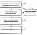
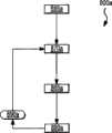
图7A是根据本发明实施例的用于给钻孔系统导向从而定向地钻出钻孔的方法的流程图;7A is a flowchart of a method for guiding a drilling system to directionally drill a borehole in accordance with an embodiment of the present invention;
图7B是根据本发明实施例的用于控制钻孔系统的方法的流程图,该钻孔系统在地层中钻出钻孔;7B is a flowchart of a method for controlling a drilling system that drills a borehole in a formation, according to an embodiment of the present invention;
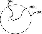
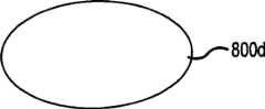
图8是根据本发明实施例的用于给钻孔系统导向的系统的示意性图示,该钻孔系统用于钻出钻孔;Figure 8 is a schematic illustration of a system for guiding a drilling system for drilling a borehole in accordance with an embodiment of the present invention;
图8A-8M显示了根据本发明实施例的钻孔控制系统的各个方面;8A-8M show various aspects of a drilling control system according to an embodiment of the invention;
图9A-9C是根据本发明实施例的用于给钻出钻孔的钻孔系统导向的系统的示意性示图;以及9A-9C are schematic illustrations of a system for guiding a drilling system for drilling a borehole in accordance with an embodiment of the present invention; and
图10显示了根据本发明实施例的钻孔控制系统的各个方面。Figure 10 shows various aspects of a drilling control system according to an embodiment of the present invention.
具体实施方式Detailed ways
接下来的描述仅仅提供了示例性实施例,并且并非为了限制本公开的范围、适用性或者配置。相反地,示例性实施例的下述描述将会向本领域技术人员提供可行的描述,用于实现一个或多个示例性实施例。本公开中元件的功能和设置可以进行各种改变,而不会脱离附加权利要求中提出的本发明的精神和范围。The ensuing description provides exemplary embodiments only, and is not intended to limit the scope, applicability, or configuration of the present disclosure. Rather, the following description of the exemplary embodiments will provide those skilled in the art with an enabling description for implementing one or more exemplary embodiments. Various changes may be made in the function and arrangement of elements of this disclosure without departing from the spirit and scope of the invention as set forth in the appended claims.
具体细节在接下来的描述中给出,来提供实施例的透彻理解。然而,本领域技术人员可以理解的是,实施例可以被实现而没有这些具体的细节。例如,系统、结构、以及其它部件可以被显示作为结构框图中的部件,从而不会使实施例在不必要的细节上模糊不清。在其它情况下,公知的工序、技术以及其它方法可以被显示而没有非必要的细节,从而避免使实施例模糊不清。Specific details are given in the ensuing description to provide a thorough understanding of the embodiments. However, it will be understood by those skilled in the art that the embodiments may be practiced without these specific details. For example, systems, structures, and other components may be shown as components in structural block diagrams in order not to obscure the embodiments in unnecessary detail. In other instances, well-known procedures, techniques, and other methods may be shown without unnecessary detail in order not to obscure the embodiments.
此外,可以认识到,单个实施例可以描述成一种工序,其被表示成流程图、流程框图、结构框图、或方块图。尽管流程图可将操作描述成连续的工序,但是许多操作可以平行地或者同时地进行。此外,操作的顺序可以重新设置。此外,任意一个或多个操作可在某些实施例中没有发生。当操作完成时工序终止,但是可具有附图中没有包括的附加步骤。工序可对应方法、流程等。Furthermore, it can be appreciated that a single embodiment may be described as a process, which is represented as a flowchart, flow diagram, structural block diagram, or block diagram. Although a flowchart may describe operations as a sequential sequence, many operations may be performed in parallel or simultaneously. Also, the order of operations can be rearranged. Additionally, any one or more operations may not occur in some embodiments. A process is terminated when the operations are complete, but may have additional steps not included in the figure. The process may correspond to a method, a flow, or the like.
本公开基本上涉及一种方法和系统,用于控制在地层中钻出钻孔的钻孔系统。更具体地,而非限制性地,本发明的实施例使用迄今为止未被认识到以及未被研究的钻孔过程的噪音-钻孔过程期间钻孔系统在钻孔内的不稳定/瞬时运动以及由于钻孔系统不稳定/瞬时运动所导致的钻孔系统与钻孔之间的相互作用-来控制钻孔系统和/或钻孔过程。The present disclosure generally relates to a method and system for controlling a drilling system for drilling a borehole in a subterranean formation. More specifically, but not limitation, embodiments of the present invention use a heretofore unrecognized and understudied noise of the drilling process - the erratic/transient motion of the drilling system within the borehole during the drilling process And the interaction between the drilling system and the borehole due to instability/transient movement of the drilling system - to control the drilling system and/or the drilling process.
本发明的实施例包含用于暂时地、以及与钻头旋转同步地防止或者禁止钻头的侧面切削头或侧面切削运动来切削钻孔的控制系统和方法。这种技术很好地适用于禁止或者调整优选静止方向或轨迹上的切削。通常地,给钻头导向是通过在一个希望钻进的方向上向钻头施加侧向作用力或者通过使钻头指向需要方向而实现。这些导向方法可以通过多种机构来实现,从靠着地层向外推动衬垫以及由此在相反方向上推动钻头,到在钻头上方在井底钻具内定向制造好的弯头。其它提出的方法包括使钻头上方的井底钻具装备非旋转偏心稳定器,其类似地在钻进时在选定方向上推动/指引钻头。Embodiments of the present invention include control systems and methods for preventing or inhibiting the side cutting head or side cutting motion of a drill bit from cutting a borehole temporarily, and synchronously with the rotation of the drill bit. This technique is well suited for inhibiting or adjusting cuts in preferred resting directions or trajectories. Typically, steering the drill bit is accomplished by applying lateral force to the drill bit in a desired direction of drilling or by pointing the drill bit in the desired direction. These steering methods can be accomplished by a variety of mechanisms, from pushing the liner outward against the formation and thus the drill bit in the opposite direction, to orienting a fabricated bend within the bottom hole tool above the drill bit. Other proposed methods include equipping the BHA above the drill bit with non-rotating eccentric stabilizers that similarly push/direct the drill bit in a selected direction while drilling.
有利地,本发明的实施例可以通过很小的附加动力需要或者不需要附加动力而获得钻头的有效导向。例如,当钻头钻进时,它要受到随机的作用力(例如在各个切削头本质上来自于瞬时反作用力的作用力),这会导致钻头在钻孔中“卡嗒作响”、在钻孔中没有优选方向地不规则移动、或者导致钻头优选地沿着旋转钻头构架内固定的特定矢量移动(如防回转钻头中的情况)。这些随机的作用力本质上随着钻头旋转而发生,并且不需要将这种作用力施加到钻头上。由此,不需要定向的施力机构来产生这种作用力。通常地,在钻头上存在随机作用力的情况下,或者在旋转的作用力矢量的情况下,钻头在地球坐标系内不会呈现出优选的定向倾向。Advantageously, embodiments of the present invention allow effective steering of the drill bit with little or no additional power requirements. For example, when a drill bit drills, it is subject to random forces (such as forces from instantaneous reaction forces in each cutting head in nature), which can cause the bit to "click" in the hole, Irregular movement in the hole with no preferred direction, or cause the drill bit to preferentially move along a specific vector fixed within the rotating drill frame (as is the case in anti-rotation drill bits). These random forces occur essentially as the bit rotates, and there is no need for such forces to be applied to the bit. As a result, no directed force-applying mechanism is required to generate this force. Typically, in the presence of random forces on the drill bit, or in the case of rotating force vectors, the drill bit will not exhibit a preferred orientation tendency within the earth coordinate system.
根据本发明的实施例,这些作用在旋转钻头上的随机定向的作用力可以得到控制,从而给钻头轨迹导向或者得到控制。为此,本发明的实施例包含有一装置,借此钻头的侧面切削刃能够被暂时地、以及与旋转同步地防止或者避免切削到钻孔。通过避免在地球坐标系内固定的特定方向上禁止切削,受到上述随机作用力的钻头将会通常地趋向于在相反方向上钻进。这种对于切削的定向禁止能够通过多种装置实现,所述装置暂时地将侧面切削刃保持成远离钻孔、或者可以减小侧面切削头在钻孔特定侧面上的切削动作。一个示例包括衬垫或相互作用元件,其保持在钻头侧刃的一个侧面上,相对于地面固定,从而不会与钻头共同旋转,其可以是足够厚以禁止侧面切削,无论何时作用在钻头上的随机作用力导致钻头向着衬垫或者相互作用元件移动。这种配置可以以多种方式扩展。通常地,这种配置禁止或者防止钻头在特定方向上的侧面切削动作。According to embodiments of the present invention, these randomly directed forces on the rotating drill bit can be controlled to steer or control the bit trajectory. To this end, embodiments of the present invention include a device whereby the side cutting edges of the drill bit can be prevented or prevented from cutting into the borehole temporarily and synchronously with the rotation. By avoiding prohibition of cutting in a particular direction fixed within the earth's coordinate system, a drill bit subjected to the random forces described above will generally tend to drill in the opposite direction. This directional inhibition of cutting can be accomplished by means of temporarily holding the side cutting edge away from the borehole, or can reduce the cutting action of the side cutting head on a particular side of the borehole. An example includes a liner or interacting element that remains on one side of the side edge of the bit, fixed relative to the ground so as not to co-rotate with the bit, which can be thick enough to inhibit side cutting whenever acting on the bit The random force on the drill causes the bit to move towards the liner or interacting element. This configuration can be extended in a number of ways. Typically, this configuration inhibits or prevents side cutting action of the drill bit in a particular direction.
通过这种装置,特定方向上的导向能够通过使装置定向而实现,从而使得装置禁止在地球坐标系内大致固定的方向上进行切削。如此定向之后,钻头能够逐渐地钻进到相反方向或者向着相反方向钻进。切削禁止装置的固定(对地静止)定向能够通过多种方式实现,例如通过井底对地静止机构、或者使切削禁止装置从表面定向的装置。用于禁止在钻头一个侧面上切削的装置能够在钻头上、在钻头侧刃上、或者刚好在钻头上方进行设置。在很多情况下,禁止装置或相互作用元件被设置在钻头大约一米之内。相互作用元件可包括衬垫、或者具有禁止在有限方位角范围内切削的期望轮廓的完全环,或者它可以包括在钻头旋转期间暂时地压制侧向切削的装置。With such a device, steering in a particular direction can be achieved by orienting the device such that the device inhibits cutting in a generally fixed direction within the earth's coordinate system. So oriented, the drill bit can drill progressively to or in the opposite direction. Fixed (geostatic) orientation of the cutting inhibiting device can be achieved in a number of ways, such as by a downhole geostationary mechanism, or a device that orients the cutting inhibiting device from the surface. The means for inhibiting cutting on one side of the drill bit can be provided on the drill bit, on the side edge of the drill bit, or just above the drill bit. In many cases, the inhibiting device or interaction element is placed within about one meter of the drill bit. The interaction element may comprise a liner, or a full ring with a desired profile that prohibits cutting in a limited range of azimuths, or it may comprise a device that temporarily suppresses side cutting during bit rotation.
在本发明的一个实施例中,提供一种系统和方法,用于控制钻出钻孔的钻孔系统与被钻进的钻孔内表面之间由于钻孔系统在钻孔过程期间不稳定/瞬时运动所导致的相互作用,允许给钻孔系统导向从而定向地穿过地层钻出钻孔。在本发明的某些方面,钻孔系统可被控制从而使得钻孔达到对象目标或者钻穿对象目标。在本发明的另一个实施例中,有关钻孔系统功能的数据可被检测到,并且用于钻出钻孔的钻孔系统与被钻进的钻孔的内表面之间的相互作用可以根据检测到的数据被控制,从而当钻孔被钻进时控制钻孔系统,即,钻头与地层之间的相互作用等。In one embodiment of the present invention, a system and method are provided for controlling the relationship between a drilling system that drills a borehole and the inner surface of a borehole that is being drilled due to instability of the drilling system during the drilling process/ The interaction caused by the transient motion allows the drilling system to be guided to drill the borehole directionally through the formation. In certain aspects of the invention, the drilling system can be controlled such that the drilling reaches or penetrates the object target. In another embodiment of the invention, data about the function of the drilling system can be detected and the interaction between the drilling system used to drill the borehole and the inner surface of the borehole being drilled can be based on The detected data is controlled to control the drilling system as the borehole is drilled, ie the interaction between the drill bit and the formation, etc.
图1是用于钻出钻孔的系统的示意性示图。如图所示,钻柱10可包括连接器系统12和井底钻具17,并且可设置在钻孔27内。井底钻具17可包括钻头20以及各种其它部件(未示出),例如钻头短接、井下马达、稳定器、钻铤、重型钻管、震击装置(震击器)、用于各种螺纹形式的转接接头和/或类似部件。井底钻具17可向钻头20提供作用力,用于破碎岩石-该作用力可以通过钻压等来提供-并且井底钻具17可被设置成在高温、高压和/或腐蚀性化学物的对机械不利的环境下存在。井底钻具17可包括井下马达、定向钻孔及测量设备、随钻测量工具、随钻测井工具和/或其它专用装置。Figure 1 is a schematic illustration of a system for drilling a borehole. As shown, drill string 10 may include connector system 12 and
钻铤可包括钻柱的可用于提供用于钻孔的钻压的部件。同样地,钻铤可包括厚壁重型管状部件,其具有中空中心,以提供钻孔流体穿过钻铤的通路。钻铤的外径可以被制成圆形,从而穿过被钻出的钻孔27,并且在某些情况下可以被机加工而具有螺旋凹槽(螺纹环)。钻铤可包括螺纹连接器、一端是阳螺纹以及另一端是阴螺纹,从而使得多个钻铤可以与其它井底工具螺纹连接在一起,从而形成井底钻具17。A drill collar may comprise a component of a drill string that may be used to provide weight-on-bit for drilling a borehole. Likewise, the drill collar may comprise a thick-walled, heavy-duty tubular member with a hollow center to provide passage for drilling fluids through the drill collar. The outer diameter of the drill collar may be rounded to pass through the drilled
重力作用在大质量钻铤上,从而提供了钻头20所需要的大的向下作用力,用来有效地破碎岩石以及钻穿地层。为了精确地控制施加到钻头20的作用力,钻井工人会认真地监测当钻头20刚好脱离钻孔27的底表面41时所测得的地面重量。接下来,钻柱(和钻头)会缓慢且小心地下降,直到它接触到底表面41。在这之后,随着钻井工人继续降低钻柱顶部,越来越多的重量施加到钻头20,并且在悬吊时相应更少重量在地面上被测得。如果地面测量显示出比当钻头20离开底表面41时小的20000磅[9080kg]的重量,那么应当有20000磅力作用在钻头20上(在垂直的孔中)。井底传感器可被用于更精确地测量钻压并且将数据传送到地面。Gravity acts on the massive drill collar to provide the high downward force required by the
钻头20可包括一个或多个切削头23。在操作中,钻头20可被用于粉碎和/或切削底表面41的岩石,从而穿过地层30而钻出钻孔27。钻头20可被设置在连接器系统12的底部上并且当钻头20变钝或者不能前进穿过地层30时钻头20可被更换。钻头20和切削头23可被设置成不同模式,从而提供用于与地层不同的相互作用以及生成不同切削模式。
传统的钻头20通过钻出稍稍大于钻头20最大外径的孔而操作,钻孔27的直径/保径由于钻头20的切削头的到达以及切削头与被钻进岩石的相互作用而产生。钻孔27被钻头20的钻进是通过旋转钻头20的切削动作以及钻头上由于钻柱质量而产生的重量的组合而实现。通常地,钻孔系统可包括保径衬垫,其可以向外延伸到钻孔27的保径。保径衬垫可包括设置在井底钻具17上的衬垫或者钻头20中部分切削头的端部上的衬垫和/或类似物。保径衬垫可被用于使钻头20在钻孔27中稳定。A
连接器系统12可包括管道-例如钻管、套管或类似物-连续油管和/或类似物。连接器系统12的管道、连续油管或类似物可被用于使地面管汇33与井底钻具17和钻头20连接。管道、连续油管或类似物可用于将钻孔流体泵送到钻头20并且使井底钻具17和/或钻头20升高、降低和/或旋转。Connector system 12 may include piping - such as drill pipe, casing, or the like - coiled tubing and/or the like. Pipeline of connector system 12 , coiled tubing or the like may be used to connect
在一些系统中,地面管汇33可包括顶驱动、旋转台或类似物(未示出),其可以将旋转运动经由管道、连续油管或类似物传递到钻头20。在某些系统中,顶驱动可由一个或多个马达(电力、液压和/或类似方式)所组成,所述马达可以通过适当齿轮而连接到管道中被称为钻轴(quill)的较短区段。钻轴可相应地螺旋连接到保护接头或者钻柱本身中。顶驱动可悬挂在吊钩上,从而使得它在井架上下地自由行进。管道、连续油管或类似物可以连接到顶驱动、旋转台或者类似物,从而将旋转运动向钻孔27下部传递到钻头20。In some systems,
在一些钻孔系统中,钻孔马达(未示出)可设置在钻孔27下面。钻孔马达可包括电力马达、液压马达和/或类似马达。液压马达可通过钻孔流体或者泵入到钻孔27中和/或在钻柱下面循环的其它流体而被驱动。钻孔马达可用于使钻头20在底表面41上具有动力/旋转。钻孔马达的使用可通过旋转钻头20而不需要旋转连接器系统12而钻出钻孔27,所述连接器系统12在钻孔过程期间可保持静止。In some drilling systems, a drilling motor (not shown) may be positioned below the
钻头20在钻孔27中的旋转运动-无论是由旋转的钻管还是由钻孔马达所产生-都用于压碎和/或打碎底表面41的岩石,从而在地层30中钻出新的一段钻孔27。钻孔流体可穿过连接器系统12或类似物而被泵入到钻孔27下面,从而向钻头20提供能量以使钻头20或类似物旋转,用于钻出钻孔27、将切削物从底表面41上移除、和/或类似操作。The rotational motion of the
在一些钻孔系统中,震击钻头以与建筑工地空气锤相同的方式垂直地敲击岩石。在其它钻孔系统中,井底马达可用于操作钻头20或者相关的钻头或者向钻头20提供除了由顶驱动、旋转台、钻孔流体和/或类似物所提供的能量之外的能量。此外,流体射流、电力脉冲和/或类似物同样可被用于钻出钻孔27或者与钻头20共同地钻出钻孔27。In some drilling systems, the hammer bit strikes the rock vertically in the same manner as a construction site air hammer. In other drilling systems, a downhole motor may be used to operate
在某些钻孔过程中,被称为弯接头的弯管(未示出)或者斜坡/铰链型机构可被设置在钻头20与钻孔马达之间。弯接头或类似物可被设置在钻孔中,从而使得钻头20以在特定方向、角度、轨迹和/或类似情况下钻出钻孔27的方式接触底表面41的外表。弯接头的位置可在钻孔中进行调节,而不需要将连接器系统12和/或井底钻具17从钻孔27移除。然而,具有弯接头或类似物的定向钻孔可能会复杂,原因是钻孔过程期间钻孔中的作用力使得弯接头难于操控和/或难于有效地使用来给钻孔系统导向。During some drilling procedures, an elbow (not shown) called an elbow or a ramp/hinge type mechanism may be provided between the
在钻孔操作期间,作用在钻头20上的作用力包括重力、由钻头20导致的转矩、施加到钻头20的端部载荷、来自于钻孔系统(包括连接器系统12)的弯矩和/或类似的力。这些作用力与被钻进的地层类型以及钻头20相对于钻孔27的底表面41外表的倾斜度共同地形成了施加的作用力以及反作用力的复杂的相互作用系统。各种系统致力于定向钻孔,通过控制/施加这些大的作用力来使钻孔系统弯曲/成形/导引/推动、和/或使用这些大的作用力和/或由于向外推动到地层30中而产生的反作用力来使钻孔系统在钻孔中定向和/或相对于钻孔27底部定向和/或推靠钻头20,从而给钻孔系统导向来定向地钻出钻孔27。During drilling operations, the forces acting on the
然而,使用钻孔过程的作用力(例如端部载荷)来给钻孔系统导向的系统可能是复杂的并且不能提供钻孔系统的精确导向。此外,通过使钻孔系统在钻孔内移动/定向和/或推动钻头20而给钻孔系统导向的系统会需要产生井底超过1kN的大的作用力和/或元件从钻柱开始延伸超过钻头切削范围相当一段距离-即远超过钻头的廓形,其中廓形可由钻头20的外部切削刃所限定-从而产生反作用力,用于移动/定向钻孔系统和/或推动钻头20。当钻孔系统旋转时为了在钻孔中推动或者移动钻孔系统,还需要通过致动器而靠着钻孔27的壁的推进力的同步施加。这种动力产生、超过钻头20切削廓形的大的延伸量和/或推进力同步会需要大的和/或昂贵的马达、和/或复杂的同步系统的操作和控制,并且会使钻井机械和钻孔过程的成本复杂和/或增加。However, systems that use the forces of the drilling process (eg, end loads) to guide the drilling system can be complex and do not provide precise guidance of the drilling system. Additionally, systems that steer the drilling system by moving/orienting the drilling system within the borehole and/or pushing the
当使用传统钻孔系统进行直线钻孔而不需要应用横向作用力或类似力时,申请人已经确定钻头20主要在钻孔中“振动”,其中振动包括钻头20在除了钻孔方向之外的方向上的反复运动。术语振动/摆动在此被用于描述钻孔系统在钻孔过程期间的反复运动,该运动可以在钻孔中沿着除了钻孔方向之外的方向并且在性质上是随机的。When drilling in a straight line using a conventional drilling system without the need to apply lateral forces or the like, applicants have determined that the
钻孔系统的这些振动/摆动会由于切削头冲击及延伸钻孔表面的效果以及由于撞击钻孔27壁的保径衬垫或类似物而受到限制。在试验中发现,包括钻头而不包括保径衬垫的钻孔系统形成的钻孔直径明显地大于包括钻头和保径衬垫的相同钻孔系统。分析这些试验的结果可以确定,在钻孔系统的操作期间,井底钻具17反复地经受运动,该运动包括在钻孔过程期间远离井底钻具17和/或钻头20的中心轴线的运动,即在径向方向上向着钻孔27的内壁40的运动。各种钻孔操作的分析发现,保径衬垫限制了井底钻具17和/或钻头20的这种径向运动,从而形成了具有较小孔的钻孔。传统钻孔系统的保径衬垫被部署用于将钻孔系统的振动运动降到最低/消除,从而提供较小的/规则的孔。These vibrations/oscillations of the drilling system will be limited due to the effect of the cutting head impacting and extending the borehole surface and due to the gauge pads or the like hitting the borehole 27 wall. It was found in tests that a drilling system including a drill bit without a gauge pad formed a borehole diameter significantly larger than the same drilling system including a drill bit and a gauge pad. Analysis of the results of these tests determined that, during operation of the drilling system, the
通过钻孔系统的试验和分析,申请人发现,当钻头20钻进地层30中时,切削头23不会均匀地与地层相互作用,例如碎片会从地层30产生,并且由此会在井底钻具17和/或钻头20中产生不稳定的运动,该不稳定的运动是在除了井底钻具17和/或钻头20的纵向/向前运动之外方向上的运动。此外,申请人分析了钻孔系统的操作并且发现:除了在钻孔系统的操作期间不稳定的/瞬时的运动之外,通过连接器系统12和钻头20施加到钻孔27的底部地层30上的作用力、钻头20的操作/旋转、钻头20与地层30在钻孔27底部的相互作用(其中钻头20可能滑动、停转、偏离钻孔轴线和/或类似的)、连接器系统12的旋转运动、顶驱动的操作、旋转台的操作、井底马达的操作、钻孔辅助的操作(例如流体射流或电力脉冲系统)、钻孔20的孔径(其可以是不规则的)和/或类似物可以产生井底钻具17和/或钻头20中的运动,并且这个运动可以是反复的、随机的、瞬时的运动,其中至少一部分运动没有沿着井底钻具17和/或钻头20的轴线导向并且相反地从井底钻具17和/或钻头20的中心处的纵向轴线向外径向地导向。由此,在钻孔操作期间,井底钻具17的运动学可包括钻孔方向上的纵向运动37以及瞬时径向运动36A和36B,其中瞬时径向运动36A和36B可包括井底钻具17从被钻进的钻孔27的中心轴线39和/或井底钻具17和/或钻头20的中心轴线远离的任意运动。Through testing and analysis of the drilling system, applicants have found that when the
通常地,已经确定出,井底钻具17在钻孔过程期间的径向运动在性质上是随机的、瞬时的。由此,井底钻具17在整个钻孔过程中会经受反复的、随机的径向/不稳定运动。为此,井底钻具17在钻孔过程期间在钻孔27中的反复径向/不稳定运动可以被称为井底钻具17和/或钻柱的动态运动、径向运动、不稳定运动、径向动态运动、径向不稳定运动、动态或不稳定运动、反复的径向运动、反复的动态运动、反复的不稳定运动、振动、振动式运动和/或类似运动。In general, it has been determined that the radial movement of the
井底钻具17在钻孔27钻进期间的动态和/或不稳定运动会在整个钻孔过程中导致/引起井底钻具17反复地与钻孔27的内表面接触和/或冲击内表面。钻孔27的内表面包括钻孔27的内壁40和底表面41,即地层30限定出钻孔27的整个表面。如前面所讨论,井底钻具17的动态和/或不稳定运动可以在性质上是随机的,并且由此在钻孔过程期间会导致/引起在井底钻具17与内表面之间随机的间歇的/反复的接触和/或冲击。Dynamic and/or erratic motion of the
在钻孔过程期间由于井底钻具17的动态和/或不稳定运动所导致的钻柱10与内表面之间的间歇的/反复的接触和/或冲击会在钻柱10的一个或多个区段/部件与内表面之间发生。例如,区段/部件可以是钻柱10靠近钻头20、井底钻具17的区段,井底钻具17的部件(例如钻铤、保径衬垫、稳定器、马达外壳),连接器系统12的区段和/或类似物。为此,钻柱10与内表面之间由于井底钻具17的动态和/或不稳定运动所导致的相互作用可被称为动态的相互作用、不稳定的相互作用、径向运动相互作用、振动相互作用和/或类似的相互作用。Intermittent/repeated contact and/or impacts between the drill string 10 and the inner surface due to dynamic and/or erratic motion of the
图2A是根据本发明实施例的用于给钻出钻孔的钻孔系统导向的系统的示意性示图。在图2A中,用于钻出钻孔的钻孔系统可包括井底钻具17,其又包括钻头20。钻孔系统可用于钻出钻孔50,该钻孔50具有内壁53和钻孔表面54。2A is a schematic illustration of a system for guiding a drilling system for drilling a borehole, according to an embodiment of the present invention. In FIG. 2A , a drilling system for drilling a borehole may include a
在钻孔过程期间,钻头20可接触钻孔表面54并且在钻孔表面54破碎/移动岩石。在本发明的实施例中,环组件55可通过顺应元件57而与井底钻具17相连接。环组件55可以是管、圆筒、框架或类似物。环组件55可具有外表面55A。During the drilling process, the
在环组件55包括管、圆筒和/或类似物的某些方面,外表面55A可包括管/圆筒的外表面和/或与管/圆筒外表面相连接的任意衬垫、突起和/或类似物。环组件55的外表面上可具有粗糙部分、涂层、突起,而用于环组件55的外表面与内壁53之间的增大的摩擦接触。环组件55可包括衬垫,其被设置成与内壁53相接触。In certain aspects where
在某些方面,环组件55可包括保径衬垫系统。在环组件55包括一系列元件(例如衬垫或类似物)的方面,外表面55A可由环组件55的各个元件(衬垫)的外表面所限定。在本发明的实施例中,环组件55可与井底钻具17一起设置以使得外表面55A在钻孔过程期间由于井底钻具17的动态运动而与内壁53和/或钻孔表面54相接合、接触和/或类似的作用。外表面55A的设计/轮廓/顺应性和/或外表面55A相对于钻头20切削廓形的布置可用于控制外表面55A与内壁53和/或钻孔表面54之间的动态相互作用。In some aspects,
顺应元件57可包括提供环组件55相对于钻头20横向移动的结构,其中横向移动是至少部分地向着井底钻具17的中心轴线61导向的运动。在某些方面,环组件55自身可被设置成横向地顺从,并且可被连接到井底钻具17和/或可以是井底钻具17的一部分,而不需要使用顺应元件57。
在本发明的一个实施例中,顺应元件57并非圆周均匀地顺应。在这个实施例中,顺应元件57中设置在顺应元件57圆周周围的一个或多个区段相比顺应元件57的其它区段会更加横向地顺应。In one embodiment of the invention, the
如前面所讨论,在钻孔过程期间,井底钻具17或者井底钻具17的一个或多个区段会经受与内壁53和/或钻孔表面54的动态相互作用。在本发明的实施例中,环组件55可被设置成使得井底钻具17的动态运动在钻孔过程期间产生环组件55与内壁53和/或钻孔表面54之间的动态相互作用。在本发明的不同方面,环组件55与井底钻具17和/或钻头20之间不同的相对外部圆周可允许环组件55与内壁53和/或钻孔表面54之间不同的动态相互作用。建模、理论分析、试验和/或类似操作可被用于选择环组件55与井底钻具17和/或钻头20之间相对外部圆周中的差异以用于特定的钻孔过程,从而产生想要的/期望的动态相互作用。As previously discussed, during the drilling process, the
在本发明的横向顺应性在顺应元件57周围沿圆周改变的实施例中,环组件55与内壁53和/或钻孔表面54之间的动态相互作用可以是围绕着环组件55在圆周上不均匀的。仅仅通过示例,顺应元件57可包括降低顺应性区域59B和增加顺应性区域59A。在某些方面,相比顺应元件57中具有降低的横向顺应性的一段(即降低顺应性区域59B)上方的环组件55与内壁53和/或钻孔表面54之间动态相互作用,在顺应元件57中具有增加的横向顺应性的一段(即增加顺应性区域59A)上方的环组件55与内壁53和/或钻孔表面54之间动态相互作用会被减弱。In embodiments of the present invention in which the lateral compliance varies circumferentially around the
在本发明的一些实施例中,环组件55可被设置成使得环组件55与井底钻具连接,从而使得环组件55被整体地设置在钻头20的切削廓形21之内,该切削廓形21包括钻头20的边到边切削轮廓。在本发明的其它实施例中,环组件55、环组件55的一段、外表面55A和/或外表面55A的一段可延伸到切削廓形21之外。仅仅通过示例,环组件55可与在井底钻具17相连接从而使得外表面55A在切削廓形21内部为1-10毫米的量级。在其它方面,以及再次仅仅通过示例,环组件55可以与井底钻具17相连接,从而使得外表面55A的至少一部分在10毫米或更大的范围内延伸到切削廓形21之外。In some embodiments of the invention, the
图2B是穿过根据本发明实施例的顺应系统的横截面视图,该顺应系统用在图2A中的用于给钻出钻孔的钻孔系统导向的系统中。横截面在图2B中显示的顺应系统57包括增加顺应性区域59A和降低顺应性区域59B。在某些方面,顺应元件57中可以只有单个区域,该区域相对于顺应元件57的剩余和/或其它区域具有增加的或降低的顺应性。在其它方面,顺应元件57可包括任意顺应设置,其围绕着顺应元件57产生非均匀的顺应性。2B is a cross-sectional view through a compliant system used in the system of FIG. 2A for guiding a drilling system for drilling a borehole in accordance with an embodiment of the present invention.
在图2B中,顺应元件57被显示成固体圆筒结构,然而,在本发明的不同方面,顺应元件可包括其它种类的结构,例如设置在井底钻具17周围以及设置成将环组件55连接到井底钻具17的多个顺应元件、能够将环组件55连接到井底钻具17并且提供环组件55横向移动的支承元件组件、和/或类似物。在本发明的其它方面,环组件55自身可以是具有整体顺应性的结构,其中整体顺应性可被选择成围绕着环组件55不是均匀的并且环组件55可以与井底钻具17相连接或者可以是井底钻具17中没有顺应元件57的区段。在另外的方面,环组件55可包括多个顺应元件,例如衬垫或类似物,该多个顺应元件与井底钻具17相连接并且至少一个顺应元件的顺应性与其它顺应元件不同。In FIG. 2B , the
在本发明的实施例中,增加顺应性区域59A可以设置在顺应元件57上,从而与降低顺应性区域59B径向相对。在这个实施例中,顺应元件57可防止环组件55在降低顺应性区域59B的位置上向内(如图2A中所示向上)移动,但是可允许环组件55在增加顺应性区域59A的位置上向内(如图2A中所示向下)移动。由此,钻头20随着在钻孔过程期间经受动态运动,因此会与内壁53和/或钻孔表面54相互作用,并且倾向于在增加顺应性区域59A的方向上和/或向着增加顺应性区域59A(如图2A中所示向上)移动、定向或者优选地破碎/移除岩石。在这个实施例中,由于在钻孔过程期间顺应元件57具有选定的非均匀顺应性,因此由于井底钻具17与钻头20的动态运动,顺应元件57可允许钻孔系统被导向以及可用于钻孔50的定向钻进。钻孔系统与钻孔27内表面的非均匀相互作用同时可用于控制钻头20与地层在钻孔过程期间的相互作用,以及由此控制钻头20的功能。In an embodiment of the present invention, the region of increased compliance 59A may be disposed on the
在本发明的实施例中,环组件55或者顺应元件57的任何不均匀圆周顺应性都用于给钻孔系统导向/控制钻孔系统。环组件55和/或顺应元件57的不同顺应性的量和/或环组件55和/或顺应元件57的非均匀顺应性的轮廓可被选定用于钻头20的期望导向响应和/或控制。钻孔系统对于顺应性差异和/或圆周顺应性轮廓的导向响应和/或钻头响应可被理论地确定、建模、通过试验推导、通过前面的钻孔过程分析等。In an embodiment of the present invention, any uneven circumferential compliance of the
在本发明中被设置成与钻孔系统共同使用的实施例中,其中钻孔系统不包括使用旋转钻头或者钻孔系统的外壳(例如井底钻具的外壳)是不旋转的,那么环组件55和/或顺应元件57可以与钻孔系统或者外壳相连接。在这个实施例中,钻孔系统可被设置在钻孔中并且增加顺应性区域59A被设置成相对钻头20具有特定定向,从而用于在增加顺应性区域59A的方向上钻出钻孔50。为了改变钻孔系统钻进的方向,增加顺应性区域59A的位置可以改变。In embodiments of the present invention that are configured for use with a drilling system, where the drilling system does not include the use of a rotating drill bit or where the housing of the drilling system (such as the housing of a bottom hole tool) is non-rotating, then the
在某些实施例中,定位装置65-可包括马达、液压致动器和/或类似物-可用于使环组件55和/或顺应元件57旋转/对齐,从而用于使钻孔系统在期望方向上钻出钻孔50。定位装置65可与处理器70进行通信。处理器70可控制定位装置65,从而用于期望的定向钻孔。处理器70可通过手动干预、对于钻孔的端点目标、期望的钻进轨迹、期望的钻头响应、期望的钻头与地层的相互作用、地震数据、来自于传感器(未示出)的输入-其能够提供有关地层的数据、钻孔50内的环境、钻孔数据(例如钻压、钻进速度和/或类似物)、钻孔系统的振动数据、动态相互作用数据和/或类似物-与钻头在地层中的位置/定向相关的数据、与钻孔的轨迹/方向相关的数据、和/或类似数据而确定出环组件55和/或顺应元件57在钻孔50中的位置。In some embodiments, a positioning device 65 - which may include a motor, hydraulic actuator, and/or the like - may be used to rotate/align the
处理器70可连接有显示器(未示出),从而显示出钻孔50的定向/方向/位置、钻孔系统、钻头20、环组件55、顺应元件57、钻孔速度、钻孔轨迹和/或类似物。显示器可以远离钻孔位置并且通过连接器(例如因特网连接、网络连接、电话连接和/或类似方式)而提供数据,并且可用于钻孔过程的远程操作。来自于处理器70的数据可存储在存储器中和/或发送到与钻孔过程相关的其它处理器和/或系统。
在本发明的另一个实施例中,导向/钻头功能控制系统可被设置成与旋转式钻孔系统共同使用,其中钻头在钻孔过程期间旋转并且由此钻头20和/或井底钻具17可在钻孔50内旋转。在这个实施例中,环组件55和/或顺应元件57可被设置从而使得环组件55和/或顺应元件57的运动与钻头20和/或井底钻具17的旋转运动不相关或者至少部分地不相关。由此,环组件55在钻井加工期间在钻孔50中被保持成对地静止。In another embodiment of the present invention, the steering/bit function control system may be configured for use with a rotary drilling system, wherein the drill bit rotates during the drilling process and thereby the
在某些方面,环组件55和/或顺应元件57可以是被动系统,其包括一个或多个设置在钻孔系统周围的圆筒。一个或多个圆筒在某些情况下可设置在钻孔系统的井底钻具17周围。一个或多个圆筒可被设置成与钻孔系统不相关地旋转。在这些方面,一个或多个圆筒可被设置成使得一个或多个圆筒与地层之间的摩擦可以使一个或多个圆筒相对于旋转的钻孔系统固定、防止圆筒的旋转运动。在本发明的某些方面,当没有钻压以及由此没有钻孔钻进时,一个或多个圆筒可被锁定到井底钻具,以及随后当钻压施加以及钻孔开始时被定向以及与井底钻具解锁;一个或多个圆筒与内表面之间的摩擦保持了一个或多个圆筒的定向。在本发明的某些方面中,一个或多个圆筒可以通过轴承或类似物而与井底钻具17相连接。In some aspects,
在本发明的某些实施例中,当处于非旋转钻孔系统中时,一个或多个圆筒的定位可以通过定位装置65来提供,该装置可以使一个或多个圆筒旋转,从而改变圆筒的起作用区域在钻孔50中的位置,继而改变钻头20的钻孔方向和/或功能。例如,顺应元件57可包括圆筒并且可围绕着井底钻具17旋转从而改变增加顺应性区域59A和/或降低顺应性区域59B的位置,以改变由于环组件55与内壁53之间动态的相互作用而导致的钻孔系统的钻进方向。作为选择,主动控制可被用于保持环组件55和/或顺应元件57相对于井底钻具17在钻孔过程期间的期望定向/位置。此外,这类装置可用在马达组件中,用来替换弯接头。这在将组件通过油管而设置在孔中以及完成约束以及当以旋转模式直线钻进时能带来好处。In some embodiments of the invention, when in a non-rotating drilling system, the positioning of the cylinder or cylinders may be provided by a
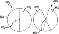
图3A-C是根据本发明实施例的用于给钻孔系统导向的凸轮控制系统的示意性图示。图3A显示了根据本发明实施例的具有凸轮控制系统的定向钻孔系统。在图3A中,钻头系统穿过地层钻出钻孔50。钻孔系统包括设置在被钻进的钻孔50端部的井底钻具17。井底钻具17包括与地层接触并且钻出钻孔50的钻头20。3A-C are schematic illustrations of a cam control system for steering a drilling system in accordance with an embodiment of the present invention. Figure 3A shows a directional drilling system with a cam control system according to an embodiment of the present invention. In Figure 3A, a drill bit system drills a borehole 50 through the formation. The drilling system comprises a
在本发明的实施例中,保径衬垫组件73可通过顺应联接器76而与井底钻具17相连接。保径衬垫组件73可包括钻铤、圆筒、钻头20的一个或多个切削头的非切削端部、和/或类似物。图3B显示了根据本发明一个方面的保径衬垫组件73。如图所示,保径衬垫组件73包括圆筒74A,其具有设置在圆筒74A表面上的多个衬垫74B。在某些方面,多个衬垫74B可具有顺应特性,然而在其它方面,多个衬垫74B可以是非顺应的并且可包括金属。在本发明的某些实施例中,保径衬垫组件73自身可以是顺应的并且顺应的保径衬垫组件可与井底钻具17的元件相连接而没有顺应联接器76。In an embodiment of the present invention, the
在本发明的一个实施例中,凸轮79可与井底钻具17相连接。凸轮79可以在井底钻具17上移动。在本发明的实施例中,凸轮79可包括偏心/非对称圆筒。凸轮79可以移动,从而与保径衬垫组件73相接触。保径衬垫组件73可被设置成在钻出钻孔50的加工期间接触内壁53和/或钻孔表面54。保径衬垫组件73可直接地与井底钻具17相连接,通过联接器或类似物连接到井底钻具17。联接器76可包括顺应/弹性材料,其允许保径衬垫组件73相对于井底钻具17移动。In one embodiment of the present invention,
凸轮79可被控制器80所致动。控制器80可包括马达、液压系统和/或类似物,并且可用于移动凸轮79和/或将凸轮79在钻孔过程期间保持成在钻孔50中对地静止。在某些方面,凸轮79可包括圆筒,其具有外表面81以及外表面81中的缩进部82。在这些方面,在钻孔过程期间,控制器80会用于将凸轮79移动到起作用位置,其中外表面81可以靠近保径衬垫组件73或者与保径衬垫组件73相接触。在本发明的某些实施例中,可没有控制器80以及凸轮79可以例如在将井底钻具17设置到钻孔50中之前被设定到起作用位置。
在本发明的一个实施例中,通过使保径衬垫组件73的特性围绕着保径衬垫组件73是不均匀的,凸轮79可被用于控制保径衬垫组件73与内壁53和/或钻孔表面54之间的动态相互作用。在本发明的另一个实施例中,除了使用凸轮79来改变保径衬垫组件73的特性、定位和/或类似之外,压电、液压和/或其它机械致动器可被用于使得保径衬垫组件73具有非均匀特性,并且非均匀特性可被用于控制保径衬垫组件73与内壁53和/或钻孔表面54之间的动态相互作用。In one embodiment of the invention, the
在起作用位置、即其中凸轮79与保径衬垫组件73相接合,保径衬垫组件73在横向方向上(即向着井底钻具17和/或钻孔50的中心轴线)的运动可被凸轮79所抵抗。在起作用位置,缩进部82可以通过间隔部83而与保径衬垫组件73分开,其中间隔部83大于保径衬垫组件73与外表面81之间在系统周围其它位置上的间隔部。由此,相比保径衬垫组件73设置在外表面81上方的其它部分,保径衬垫组件73位于缩进部82上方的部分可具有更多的自由度/能力来横向地移动。因此,保径衬垫组件73与内壁53和/或钻孔表面54之间的相互作用在钻孔过程期间围绕着保径衬垫组件73将是不均匀的。In the active position, i.e., where the
在本发明的某些方面,凸轮79可被用于控制保径衬垫组件73的偏移,或者是产生保径衬垫组件73的偏移来给钻孔系统导向、或者是减小保径衬垫组件73的偏移以便直线钻孔。在用于控制钻头20操作的实施例中,凸轮79可被用于控制保径衬垫组件73的偏移,或者是产生保径衬垫组件73的偏移来产生钻头20的某些行为或者是减小保径衬垫组件73的偏移以便获得钻头20的不同行为。In certain aspects of the invention,
凸轮79可包括偏心圆筒。在操作中,凸轮79可与保径衬垫组件73相接合并且可使得至少一段保径衬垫组件73相对于钻头20是大于保径的。由此,大于保径的保径衬垫组件73可以与钻孔50的内表面以不均匀的方式相互作用。凸轮79可具有外径稳定改变的区段,从而使至少一段保径衬垫组件73的保径/直径在钻孔过程期间稳定地改变。
在钻孔过程期间,井底钻具17可在钻孔50中经受动态的运动,导致了井底钻具17与钻孔50内表面之间的动态相互作用。在本发明的一个实施例中,由于与保径衬垫组件73在保径衬垫组件73中相对于缩进部82的相对侧面上的位置相比,保径衬垫组件73在缩进部82上方的更大顺应性,保径衬垫组件73与内壁53和/或钻孔表面54之间反复的动态相互作用将导致钻孔系统在钻孔方向85上钻进,其中钻孔方向85指向缩进部82的方向。当接合时,凸轮79将会阻止保径衬垫组件73向内(如图所示向上)移动,但是允许保径衬垫组件73在相反方向(如图所示向下)移动。由此,钻头20将会相对于保径衬垫组件73向上移动、振动并且由此用于通过钻孔系统在向上方向上、向着缩进部82钻进,从而形成钻孔50的向上指引区段。During the drilling process, the
在本发明的实施例中,凸轮79可用于使保径衬垫组件73的轴线在对地静止平面内相对于钻头20轴线发生偏移。在某些方面,保径衬垫组件73通过凸轮79的偏移可被提供,同时保径衬垫组件73与钻头20和/或井底钻具17共同旋转。In an embodiment of the invention, a
当使用钻孔系统来钻出钻孔的弯曲部分时,例如具有10度/100英尺斜度的弯曲部分,钻孔的实际侧钻将会是小的,例如在这种弯曲部分,对于150mm(6英寸)钻孔的前向钻进,钻孔的侧钻为0.07mm。在本发明的实施例中,由于用于形成具有10度/100英尺斜度的弯曲部分的侧钻是小的,因此在钻孔过程期间与钻孔内表面形成受控制的、不均匀动态相互作用的系统可仅仅需要产生钻孔的小的偏斜。在本发明实施例的试验中,使用相对于井底钻具和/或钻头的中心轴线具有偏心圆周轮廓的钻铤/保径衬垫组件对动态相互作用的控制、包括相对于钻头为大于保径和/或小于保径的偏心轮廓,形成了钻孔具有这种期望曲率的弯曲部分的导向。When using the drilling system to drill out a curved portion of the borehole, for example with a 10 degree/100 foot slope, the actual sidetracking of the borehole will be small, e.g. in such a curved portion, for 150mm ( 6 inches) for the forward drilling of the borehole, and the sidetracking of the borehole is 0.07mm. In an embodiment of the invention, since the sidetracking used to form the bend with a 10 degree/100 ft inclination is small, it creates a controlled, non-uniform dynamic interaction with the borehole inner surface during the drilling process. A functioning system may only need to produce a small deflection of the borehole. In tests of embodiments of the present invention, control of dynamic interactions, including greater than the gauge liner relative to the drill bit, was performed using a drill collar/gage liner assembly having an eccentric circumferential profile relative to the central axis of the BHA and/or bit. The eccentric profile of the diameter and/or less than the gauge forms a guide for the curved portion of the borehole with this desired curvature.
在本发明的某些方面,为了将动力需要降到最低,保径衬垫组件73可被固定到顺应联接器76上,并且保径衬垫组件73的轴线与钻头20和/或可包括钻头20的切削系统的轴线重合。在本发明的实施例中,钻孔系统的导向可以这样实现,通过使用凸轮79以约束顺应联接器76的顺应方向,因此保径衬垫组件73可在一个方向上移动,但是在相对方向上是非常刚性的(抵抗径向运动)。在某些方面,为了给钻孔系统导向以直线地钻进,凸轮79可被接合,从而使得保径衬垫组件73的运动在所有方向上都是刚性的(抵抗径向运动)。In certain aspects of the invention, to minimize power requirements,
在本发明的实施例中,保径衬垫组件73可包括支承合乎钻头20保径的保径衬垫的单个钻铤组件。在某些方面,小量的大于保径和小于保径是可以容忍的。在可选实施例中,保径衬垫组件73上的衬垫可以被独立地固定到环组件上和/或可以独立地控制。保径衬垫组件73可被固定到刚性顺应结构上以及可以相对于钻头20径向地移动。凸轮79可以是偏心的以及可以被设置成当钻孔系统导向时对地静止,以及当钻柱被卡住或者不是期望的导向时被停下、移除和/或类似操作。通过将凸轮79保持在对地静止位置,凸轮79的起作用部位、例如缩进部83或者类似部位可被保持在相对于钻孔50的对地静止位置从而用于在期望方向上、例如在对地静止缩进部83的方向上钻进钻孔50。在某些方面,凸轮79可以是对地静止的并且保径衬垫或者类似物可以在钻孔过程期间自由地旋转。In an embodiment of the invention, the
如前面所述,各种方法可用于使保径衬垫组件73与钻头20和/或井底钻具17相连接。在某些方面,安装部可以是径向顺应的,但是也可以将转矩和轴向重量传递到井底钻具17。在本发明的一个实施例中,可以是安装部或者类似物的顺应联接器76可包括薄壁圆筒,在圆筒中刻有槽,从而允许径向柔性但是保持切向及轴向刚性。其它实施例可包括用于传递重量的轴承表面和/或用来传递转矩的销和/或枢转臂。As previously described, various methods may be used to couple the
通过使用能够保持缩进部82(或凸轮79的大于保径、小于保径部分,或者凸轮79与保径衬垫组件73的组合,或者保径衬垫组件73的径向刚性或径向顺应部分)在钻孔50中对地静止的保径衬垫组件73和/或顺应联接器76的配置,钻孔系统可被控制从而定向地钻出钻孔50。在本发明的某些实施例中,处理器75可被用于在钻孔操作期间或者钻孔操作之间管理控制器80,以便凸轮79的旋转,从而连续地控制钻孔过程的方向。在一些实施例中,缩进部82可具有带斜度的外形82A,从而用于改变缩进部82的深度。在这个实施例中,保径衬垫组件73在保径衬垫组件73处于缩进部82上方的部分与保径衬垫组件73没有处于缩进部82上方的部分之间的相对顺应性可以是改变的。由此,在本发明的某些实施例中,钻孔方向85的锐度(θ)86能够以可变方式控制。By using the over-gauge, under-gauge portion of the
在本发明的某些方面,多个缩进部可设置在凸轮79中,从而用于保径衬垫组件73与内壁53之间相互作用的控制。多个缩进部可设置在凸轮79圆周周围的不同位置,从而提供期望的导向效果。此外,多个凸轮可以与井底钻具17上的一个或多个保径衬垫组件73共同使用,从而在钻孔过程期间提供不同的导向效果。In certain aspects of the invention, multiple indentations may be provided in the
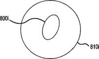
图4A-C是根据本发明实施例的主动保径衬垫系统的示意性图示,该系统用于控制设置用于钻出钻孔的钻孔系统。在本发明的实施例中,主动保径衬垫100可用于控制钻孔系统,该钻孔系统用于钻出钻孔并且可包括连接有井底钻具95的钻管90。井底钻具95可包括钻头97,用于钻出钻孔。主动保径衬垫100可包括与被钻进的钻孔内表面以不均匀方式相互作用的钻铤、保径衬垫、井底钻具的区段、管状组件、钻头的区段和/或类似物。4A-C are schematic illustrations of an active gauge liner system for controlling a drilling system configured to drill a borehole in accordance with an embodiment of the present invention. In an embodiment of the present invention, the active gauge liner 100 may be used to control a drilling system for drilling a borehole and may include a drill pipe 90 to which a
主动保径衬垫100可包括与钻孔系统相连接的盘、圆筒、多个单个元件(例如一系列围绕着井底钻具95或者钻管90圆周设置的衬垫)并且可以在钻孔过程期间与被钻进的钻孔的内表面相互作用。在某些方面,为了主动保径衬垫100或类似物与钻孔内表面之间反复的相互作用,主动保径衬垫100可以与钻孔系统相连接,从而相距钻头97小于20英尺。在其它方面,主动保径衬垫100可以与钻孔系统相连接,从而相距钻头97小于10英尺。The active gage liner 100 may comprise a disc, a cylinder, a plurality of individual elements (such as a series of liners disposed around the circumference of the
在本发明的实施例中,主动保径衬垫100可以在钻孔中移动。由此,主动保径衬垫100可以通过致动器或者类似物而在钻孔中对齐到钻孔内的定向,从而作为主动保径衬垫100在钻孔中定向时与钻孔内表面的非均匀相互作用的结果,产生钻孔系统的期望控制。使用处理器或类似物来控制主动保径衬垫100在钻孔内的定位,钻孔系统的操作和/或导向可被控制/管理,并且这种控制/管理在某些方面可以实时发生。In an embodiment of the present invention, the active gage pad 100 is movable in the borehole. Thus, the active gage pad 100 can be aligned in the borehole by an actuator or the like to an orientation within the borehole, thereby serving as an alignment between the active gage pad 100 and the inner surface of the borehole when the active gage pad 100 is oriented in the borehole. As a result of the inhomogeneous interactions, desired control of the drilling system results. Using a processor or the like to control the positioning of the active gauge pad 100 within the borehole, the operation and/or steering of the borehole system can be controlled/managed, and such control/management can occur in some aspects in real-time.
在图4A中,主动保径衬垫100与井底钻具95相连接,用于与被钻进的钻孔的内表面在靠近钻头97的位置上进行相互作用。在钻管90、井底钻具95和/或类似物在钻孔操作期间旋转的钻孔系统中,主动保径衬垫100可被设置成在钻孔操作期间保持成对地静止。致动器、摩擦作用力和/或类似物可被用于将主动保径衬垫100保持成对地静止。仅仅通过示例,在本发明的一个实施例中,主动保径衬垫可在钻头97后面小于10-20英尺的距离与井底钻具95连接在一起。In FIG. 4A , an active gauge liner 100 is attached to the
图4B显示了图4A中所示的系统的主动保径衬垫的一个实施例。在附图4B中,根据本发明的实施例,主动保径衬垫100A可包括不对称的元件。通过使不对称主动保径衬垫与钻柱相连接,从而使得保径衬垫100A的外表面延伸到钻柱的外表面之外,不对称主动保径衬垫的外表面可与被钻进的钻孔的内表面相互作用。由于主动保径衬垫100A具有非对称外表面,因此作为钻柱在钻孔过程期间以非均匀方式的动态运动的结果,主动保径衬垫100A可与钻孔内表面相互作用,非均匀方式取决于主动保径衬垫100A的非对称设置。Figure 4B shows one embodiment of an active gauge pad of the system shown in Figure 4A. In FIG. 4B, an active gauge pad 100A may include asymmetrical elements in accordance with an embodiment of the present invention. By connecting the asymmetric active gauge liner to the drill string such that the outer surface of the gauge liner 100A extends beyond the outer surface of the drill string, the outer surface of the asymmetric active gage liner can interface with the drilled The inner surface of the borehole interacts. Since the active gage liner 100A has an asymmetric outer surface, the active gage liner 100A can interact with the borehole inner surface in a non-uniform manner as a result of the dynamic movement of the drill string during the drilling process in a non-uniform manner. Depends on the asymmetric arrangement of the active gauge pad 100A.
仅仅通过示例,主动保径衬垫100A可以在设计上是非对称的并且可被设置成与如图4A中所示的井底钻具在钻头后面几个英寸到10-20英尺范围的距离相连接。在某些实施例中,主动保径衬垫100A可包括均匀的圆筒以及可偏心地设置在井底钻具上,用于与内表面的非均匀相互作用,作为钻柱动态运动的结果。By way of example only, the active gauge liner 100A may be asymmetric in design and may be configured to interface with a bottom hole assembly as shown in FIG. 4A at a distance ranging from a few inches behind the bit to 10-20 feet. . In certain embodiments, the active gauge liner 100A may comprise a uniform cylinder and may be disposed eccentrically on the bottom hole assembly for non-uniform interaction with the inner surface as a result of dynamic motion of the drill string.
在某些实施例中,主动保径衬垫100A可包括对地静止管件以及在一侧上稍稍地为小于保径。在其它实施例中,主动保径衬垫100A可在一个侧面上为小于保径以及在相对侧面上为大于保径。在某些方面,主动保径衬垫100A可包括多个对地静止管件,其在圆周上为小于保径/大于保径并且可围绕着钻管90和/或井底钻具95的圆周连接。在本发明的某些实施例中,主动保径衬垫100A可被设置成使得主动保径衬垫100A与钻柱相连接从而使得主动保径衬垫100A与钻头的切削廓形整体地设置;切削廓形包括钻头的边到边切削轮廓。在本发明的其它实施例中,主动保径衬垫100A的一部分或者全部可延伸到钻头的切削廓形之外。In certain embodiments, the active gauge liner 100A may comprise a geostationary tubular and be slightly smaller than the gauge on one side. In other embodiments, the active gauge liner 100A may be under-gauge on one side and over-gauge on the opposite side. In certain aspects, the active gauge liner 100A may comprise a plurality of geostationary tubulars that are circumferentially under/over gauge and may be connected around the circumference of the drill pipe 90 and/or
仅仅通过示例,主动保径衬垫100A可与钻柱相连接,从而使得主动保径衬垫100A的外表面处于切削廓形之内1-10毫米量级。在其它方面,以及再次仅仅通过示例,主动保径衬垫100A可与钻柱相连接从而使得主动保径衬垫100A的外表面的至少一部分在十分之一到10或更多毫米的范围内延伸到切削廓形之外。By way of example only, the active gage pad 100A may be coupled to the drill string such that the outer surface of the active gage pad 100A is on the order of 1-10 millimeters within the cutting profile. In other aspects, and again by way of example only, the active gage liner 100A can be connected to the drill string such that at least a portion of the outer surface of the active gage liner 100A is in the range of one-tenth to 10 or more millimeters Extends beyond the cutting profile.
在本发明的实施例中,由于钻孔系统在钻进加工期间在钻孔中以非均匀的方式的径向运动,主动保径衬垫100A-由于主动保径衬垫100A与井底钻具是非同心的、非对称的和/或类似的-可与被钻进的钻孔的内表面相互作用。如图4B中所示,主动保径衬垫100A与钻孔内表面之间的反复的动态相互作用在钻孔过程期间将会导致钻孔系统在向下方向103上钻进,如图中所示。通过将主动保径衬垫100A保持成在钻孔过程期间对地静止,主动保径衬垫100A可被用于给钻孔系统导向。In an embodiment of the present invention, due to the radial movement of the drilling system in the borehole in a non-uniform manner during the drilling process, the active gauge liner 100A—since the active gauge liner 100A interacts with the bottom hole Be non-concentric, asymmetrical, and/or similar-may interact with the inner surface of the borehole being drilled. As shown in FIG. 4B, the repeated dynamic interaction between the active gauge pad 100A and the inner surface of the borehole during the drilling process will cause the drilling system to drill in the
在本发明的实施例中,通过使主动保径衬垫100A在主动保径衬垫100A的圆周周围的至少一个圆周位置上为小于保径,主动保径衬垫100A与内表面之间可以形成小间隙,其用于给钻头97导向。由此,在本发明的一些实施例中,钻孔系统可通过井底钻具95上的接触表面而被导向,该井底钻具95可以在被切削头切削的轮廓之内和/或不需要将接触表面推到切削轮廓之外。In the embodiment of the present invention, by making the active gauge pad 100A smaller than the gauge at least one circumferential position around the circumference of the active gauge pad 100A, a gap between the active gauge pad 100A and the inner surface can be formed. A small gap, which is used to guide the drill bit 97. Thus, in some embodiments of the invention, the drilling system may be steered through contact surfaces on the
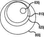
图4C显示了图4A中所示的系统的主动保径衬垫的另一个实施例。在图4C中,主动保径衬垫100B可包括与可延伸元件107相连接的环105。环105可包括圆筒、盘、钻铤、保径衬垫、井底钻具95的一段、钻柱的一段、钻管的一段和/或类似物。Figure 4C shows another embodiment of the active gage pad of the system shown in Figure 4A. In FIG. 4C , the active gauge pad 100B may include a
在本发明的实施例中,可延伸元件107可以是可被控制从而改变环105的圆周轮廓的元件。可延伸元件107可通过控制器110而被控制/致动。控制器110可包括马达、液压系统和/或类似物。在本发明的实施例中,控制器110可致动可延伸元件107,从而从井底钻具95向外延伸,从而改变由于钻孔系统在钻孔过程期间在钻孔中的径向/动态运动所导致的主动保径衬垫100B与被钻进的钻孔的内表面之间的动态相互作用。In an embodiment of the invention, the
在本发明的一些实施例中,主动保径衬垫100B可被设置成使得当延伸时主动保径衬垫100B被整体地设置在钻头切削廓形之内。在本发明的其它实施例中,延伸的/部分延伸的主动保径衬垫100B中的一段或整体可延伸到钻头切削廓形之外。仅仅通过示例,主动保径衬垫100B可与钻柱相连接,从而使得主动保径衬垫100B在延伸位置的外表面处于切削廓形之内1-10mm的量级。在其它方面,以及再次仅仅通过示例,主动保径衬垫100B可与钻柱相连接从而使得主动保径衬垫100B的至少一部分外表面在延伸或者部分延伸时能够在十分之一到10或更多毫米的范围内延伸到切削廓形之外。In some embodiments of the invention, the active gauge pad 100B may be configured such that when extended, the active gauge pad 100B is integrally disposed within the cutting profile of the drill bit. In other embodiments of the invention, a section or the entirety of the extended/partially extended active gauge pad 100B may extend beyond the bit cutting profile. By way of example only, the active gage pad 100B may be coupled to the drill string such that the outer surface of the active gage pad 100B in the extended position is on the order of 1-10 mm within the cutting profile. In other aspects, and again by way of example only, the active gage liner 100B may be connected to the drill string such that at least a portion of the outer surface of the active gage liner 100B is able to travel between one-tenth to 10 or More millimeters extend beyond the cutting profile.
在本发明的实施例中,主动保径衬垫100B与内表面之间的相互作用可通过可延伸元件107的定位/延伸而被控制,从而用于钻孔系统的导向以及被钻孔系统钻进的钻孔的定向钻进。在某些方面,处理器70接收到有关期望钻进方向的数据、有关钻孔过程的数据、有关钻孔的数据、有关钻孔内情况的数据、地震数据、有关钻孔周围地层的数据和/或类似数据,并且可以操作控制器110,从而用于可延伸元件107的定位/延伸,以给钻孔系统导向。在本发明的实施例中,可延伸元件107可以延伸从而调节主动保径衬垫100与被钻进的钻孔的内表面之间的动态相互作用。这需要可延伸元件107的简单被动延伸,从而使得主动保径衬垫100具有围绕着钻孔系统和/或钻孔的中心轴线的非均匀形状,而不需要在内表面上施加驱动力或者作用力。In an embodiment of the invention, the interaction between the active gauge pad 100B and the inner surface can be controlled by the positioning/extension of the
然而,在某些方面,可延伸元件107可被定位、延伸,从而在内表面上施加作用力。仅仅通过示例,在某些实施例中,可延伸元件107可以在内表面上施加小于1kN的作用力,从而使得来自于内表面的反作用力施加到钻孔系统上以及钻孔系统与内表面之间的动态相互作用的控制。操作可延伸元件107从而施加小于1kN的作用力可以是有利的,原因是作用力不需要大的井底动力消耗/动力源、可减少控制器110的尺寸和复杂度、和/或类似情况。In some aspects, however, the
在本发明的实施例中,井底钻具95、钻头97、主动保径衬垫100和/或类似物可被设置成具有不规则分布的质量。井底钻具95、钻头97、主动保径衬垫100和/或类似物的质量可以沿着圆周或者类似地发生改变从而使得钻孔系统的不稳定运动和/或钻孔系统与钻孔内表面之间的相互作用是不均匀的。由此,钻孔系统的不均匀加重可用于钻孔系统的控制和/或导向。仅仅通过示例,提供钻压的钻铤可以是具有非均匀重量分布的圆筒。在某些方面,圆筒形钻铤可以旋转以相对于井孔改变非均匀重量/质量分布的形式,从而用于钻孔系统的期望控制和/或钻孔系统的导向。In embodiments of the present invention,
在本发明的某些实施例中,除了保径衬垫、钻铤和/或类似物之外或者与保径衬垫、钻铤和/或类似物相结合,钻柱可被成形以用于控制与内表面的不稳定相互作用。例如,井底钻具95可以不对称地成形、具有不对称的顺应性和/或类似的。此外,根据本发明的一些实施例,钻头97可以是不对称的、具有不对称的顺应性、具有不均匀的切削特性和/或类似特性。此外,钻孔系统可被设置成加强钻孔系统在钻孔过程期间的不稳定运动。建模、试验和/或类似情况可被用于设计具有增强的不稳定运动的钻孔系统。切削头在钻头97上的定位、切削头操作参数可被用于增强的不稳定运动。在本发明的某些实施例中,钻孔系统包括可用于加强不稳定相互作用的柔性/顺应的联接器、弯接头和/或类似物(未示出),以加强钻孔系统对于不稳定的相互作用和/或类似物的控制。In certain embodiments of the invention, the drill string may be shaped for use in addition to or in combination with gauge liners, drill collars, and/or the like Controls unstable interactions with interior surfaces. For example, the
图5提供了根据本发明实施例的反复径向运动致动器系统的示意性图示,该系统用于给钻孔系统导向从而定向地钻出钻孔。在本发明的实施例中,钻孔系统可包括钻柱140-其可相应地包括井底钻具95-并且钻孔系统可被设置成用于穿过地层钻出钻孔。5 provides a schematic illustration of a repetitive radial motion actuator system for guiding a drilling system to directionally drill a borehole in accordance with an embodiment of the present invention. In an embodiment of the invention, a drilling system may include a drill string 140 - which may in turn include a bottom hole assembly 95 - and may be configured to drill a borehole through an earth formation.
在某些实施例中,径向运动发生器150可被连接到钻柱140。径向运动发生器150可被设置成产生井底钻具95在钻孔中的径向运动,其中径向运动可以是井底钻具95远离钻孔中心轴线而指向钻孔内壁的任意运动。径向运动发生器150可包括机械振动器、声波振动器和/或类似物,可产生井底钻具95反复的径向运动,例如振动。径向运动发生器150可以被调谐以适应钻柱140和/或井底钻具95的物理特性,以增强所产生的径向运动。In some embodiments,
在本发明的实施例中,井底钻具95与钻孔内表面之间的相互作用可以通过径向运动发生器150而被产生、加强、改变和/或类似操作。径向运动发生器150可通过在井底钻具与钻孔内表面之间产生、施加、改变和/或类似操作相互作用而给钻柱140导向。通过给钻柱140导向,被钻柱140钻出的钻孔可被定向地钻出。处理器155可被用于控制径向运动发生器150,从而在井底钻具95与内表面之间产生相互作用,从而给钻柱140在期望方向上导向。In an embodiment of the present invention, the interaction between the
在本发明的一些实施例中,径向运动发生器150可以与在钻孔系统与被钻进的钻孔的内表面之间产生不均匀的不稳定相互作用的其它方法(例如在该说明书中所描述的)共同使用。在这个实施例中,径向运动发生器150可用于增强或者抑制钻柱的不稳定运动,从而增强/抑制不稳定相互作用控制器的作用和/或控制不稳定相互作用控制器。由此,不稳定相互作用控制器可作为不稳定相互作用控制器的控制器/管理器,并且自身可被处理器所控制用于控制/导向钻孔系统和/或增加/抑制不稳定相互作用控制器与钻孔内表面之间不均匀的不稳定的相互作用。In some embodiments of the invention, the
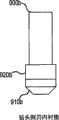
图6A和6B显示了根据本发明实施例的用于选择性地使钻孔系统的内表面特征化的系统,该系统用于给钻孔系统导向从而定向地钻出钻孔。在钻孔过程中,钻柱160可被用于穿过地层钻出钻孔。钻柱160可包括井底钻具165和联接器170,该联接器170将井底钻具165与地面位置或者地面位置附近的设备相连接。井底钻具可包括钻头173,该钻头包括多个齿174,用于敲碎/压碎地层中的岩石,从而形成/延伸被钻进的钻孔。6A and 6B illustrate a system for selectively characterizing the interior surface of a drilling system for guiding the drilling system to directionally drill a borehole, in accordance with an embodiment of the present invention. During drilling,
在钻孔过程期间,被钻进的钻孔的内表面可在形状上稍稍规则并且可由钻头173的外径所限定。通常地,内表面形状稍稍为圆形。地层不同部分的特性可导致内表面形状的不规则。在图6A中,根据本发明的实施例,成形装置180可与内表面相互作用从而改变内表面/使内表面成形。成形装置180可包括用于将流体喷射到内表面上的流体喷射系统、被设置成横向地钻进内表面中的钻头、用于使内表面破碎的破碎机,和/或类似装置。During the drilling process, the inner surface of the borehole being drilled may be somewhat regular in shape and may be defined by the outer diameter of the
在本发明的实施例中,成形装置180可被用于改变内表面的轮廓,从而控制井底钻具165与内表面之间的相互作用。在某些方面,保径衬垫185可与井底钻具165在靠近钻头173处相连接并且可被设置成在钻孔被钻孔系统钻进期间与内表面相互作用。尽管内表面相对均匀,但是保径衬垫185与内表面之间由于井底钻具165在钻孔过程期间的径向运动所导致的随机相互作用通常地是均匀的并且不会影响钻进的方向。在本发明的实施例中,成形装置180可勾勒/成形内表面,从而控制保径衬垫185与内表面之间的相互作用。在本发明的某些方面,井底钻具165可不包括保径衬垫185并且相互作用可直接地在井底钻具165与内表面之间。In an embodiment of the invention, shaping
在本发明的实施例中,通过控保径衬垫185与内表面之间的相互作用使钻孔系统被导向。在某些方面,成形装置180可以在导向过程中保持对地静止,以便当钻柱140和/或钻柱140的部件可在钻孔内移动/旋转时在钻孔过程期间精确地选择由成形装置180成形的内表面的区域。In an embodiment of the invention, the drilling system is steered by controlling the interaction between the
成形装置180可包括安装在钻头的保径切削头与保径衬垫之间的水喷射。水喷射或类似物可被用于底切保径衬垫前方的地层,从而在内表面与保径衬垫之间产生间隙,其可以用于使根据本发明实施例的钻孔系统的振动导向。在其它实施例中,电力脉冲系统可安装到保径衬垫前方并且可被用于使一段内表面软化从而允许保径衬垫压碎这个区段的材料,从而产生间隙,用于根据本发明实施例的钻孔系统的振动导向。在其它实施例中,电力脉冲系统可被用于直接地产生间隙。The
在图6B中,钻头173可被设置成钻出具有选择性不均匀内表面的钻孔。在某些方面,钻头173的齿190可被设置成选择性地致动,从而提供内表面上的轮廓。在其它方面,不同技术可被用于控制钻头173以选择性地成形内表面。通过在内表面上选择性地设置槽、凹进或者类似结构来控制内表面的轮廓和形状,内表面与井底钻具165之间由于井底钻具165在钻孔钻进期间的径向运动所导致的相互作用可被控制并且钻孔方向由此也可被控制。在某些方面,钻头173可包括机械切削头,其可被实施成优选地切削内表面的一侧。In Figure 6B,
图7A是根据本发明实施例的用于给钻孔系统导向从而定向地钻出钻孔的方法的流程图示。在步骤200中,钻孔系统可被用于穿过地层钻出一段钻孔。钻孔系统可包括钻柱,该钻柱连接到地面设备或类似物。钻柱自身可包括井底钻具,其包括钻头用于接触地层以及穿过地层钻出一段钻孔。井底钻具可通过钻管、套管、连续油管或类似物而被连接到地面设备。钻头可由顶驱动、旋转台、马达、钻孔流体和/或类似物来供给动力。在钻孔过程期间,钻柱可经受钻孔中的随机运动,该随机运动可包括径向振动,该振动导致钻柱在钻孔过程期间反复地接触钻孔的内表面。钻柱与内表面之间由于径向振动所导致的相互作用可在钻孔底部最为明显,此处相互作用会在井底钻具与内表面之间发生。7A is a flowchart illustration of a method for steering a drilling system to directionally drill a borehole in accordance with an embodiment of the present invention. In
在步骤210中,钻柱与内表面之间的振动式相互作用可被控制。在本发明的某些实施例中,动态相互作用的控制会发生在钻孔底部。在本发明的一些实施例中,装置可被用于钻孔底部使得井底钻具与内表面之间的振动式相互作用不是均匀的。在这个实施例中,控制钻柱与内表面之间振动式相互作用的步骤可包括在内表面圆周周围的位置上对井底钻具与内表面之间的振动式相互作用进行抑制和/或增强。内表面圆周周围的抑制和/或增强位置会随着钻孔被钻进而被保持或者改变。在某些方面,多个装置可被用于在井底钻具与内表面之间产生不均匀的相互作用。In
在本发明的实施例中,相互作用元件可被用在步骤212中用于控制动态的相互作用。相互作用元件可以是独立的元件,例如钻铤、保径衬垫组件、圆筒或类似物,其可与钻柱连接,并且在某些方面与井底钻具连接,可以是钻柱的一段、例如井底钻具的一段,或者类似情形。相互作用元件可被设置成提供相互作用元件与被钻进的钻孔内表面之间均匀的相互作用。In an embodiment of the invention, interaction elements may be used in
通常地,被钻进的钻孔是地层中具有基本上圆筒形内表面的钻孔。由此,在部分方面,相互作用元件可包括具有相对于钻柱和/或钻孔中心轴线不均匀的轮廓的元件。仅仅通过示例,相互作用远见可包括与井底钻具相连接的偏心圆筒,其中当与井底钻具连接时,偏心圆筒的中心轴线不与井底钻具的中心轴线重合。在另一个示例中,相互作用元件可包括设置在井底钻具周围的一系列衬垫,所述衬垫被设置成在钻孔过程期间接触钻孔的圆筒形内表面,其中至少一个衬垫被设置成相比其它衬垫从井底钻具向外延伸更少或更大程度。Typically, the borehole being drilled is a borehole in the formation having a substantially cylindrical inner surface. Thus, in part, the interaction element may comprise an element having a profile that is non-uniform relative to the drill string and/or borehole central axis. By way of example only, the interaction vision may include an eccentric cylinder coupled to the bottom hole tool, wherein the central axis of the eccentric cylinder does not coincide with the central axis of the bottom hole tool when coupled to the bottom hole tool. In another example, the interaction element may comprise a series of pads disposed about the bottom hole assembly, the pads configured to contact the cylindrical inner surface of the borehole during the drilling process, wherein at least one of the pads The pads are configured to extend outwardly from the bottom hole assembly to a lesser or greater extent than other liners.
在其它实施例中,相互作用远见可包括具有不均匀顺应性的元件。仅仅通过示例,顺应元件可包括具有特定顺应性的元件,以及元件的一段与元件剩余部分的特定顺应性相比具有增加的或者降低的顺应性,并且被设置成使得增加或者降低顺应性的区域的至少一部分以及具有特定顺应性元件的至少一部分在钻孔过程期间由于井底钻具的动态运动而各自接触圆筒形内表面。在本发明的某些实施例,致动器可被用于改变相互作用元件的特性,从而致动相互作用元件从均匀地与钻孔内表面相互作用的元件到以不均匀的方式与内表面相互作用的元件。In other embodiments, the interaction vision may include elements with non-uniform compliance. By way of example only, a compliant element may include an element having a particular compliance, and a section of the element having increased or decreased compliance compared to the specified compliance of the remainder of the element, and arranged such that the region of increased or decreased compliance At least a portion of and at least a portion of the specifically compliant element each contact the cylindrical inner surface during the drilling process due to dynamic motion of the bottom hole assembly. In some embodiments of the invention, an actuator may be used to change the characteristics of the interacting element, thereby actuating the interacting element from an element that interacts uniformly with the inner surface of the borehole to an element that interacts with the inner surface in a non-uniform manner. interacting elements.
在本发明的某些实施例中,相互作用元件,无论是具有不均匀轮廓、不均匀顺应性和/或类似的元件,都可以被设置成不在内表面上施加压力或者推靠该内表面,而是本质上是被动的并且在钻孔过程期间由于钻柱的动态运动而与内表面相互作用。例如,相互作用元件可包括可延伸元件,其从钻柱开始向外延伸。在部分方面,作用力可通过可延伸元件施加到内表面上,但是出于简化及经济的原因,作用力可在性质上是小的,即作用力小于1kN左右。In some embodiments of the invention, the interaction elements, whether of non-uniform profile, non-uniform compliance and/or the like, may be arranged so as not to exert pressure on or push against the inner surface, Rather, it is passive in nature and interacts with the inner surface during the drilling process due to the dynamic motion of the drill string. For example, the interaction element may comprise an extendable element that extends outwardly from the drill string. In some respects, the force can be applied to the inner surface by the extendable element, but for reasons of simplicity and economy, the force can be small in nature, ie less than 1 kN or so.
在本发明的一些实施例中,相互作用元件可被设置成不延伸到钻头切削头的廓形之外和/或被整体地设置在廓形之内。在其它实施例中,相互作用元件可具有至少一部分可延伸到钻头廓形之外。在本发明的某些方面,相互作用元件可延伸到钻头和/或切削头的廓形外部之外的1mm到10几毫米范围内,这种延伸范围用于导向/控制钻孔系统。In some embodiments of the invention, the interaction elements may be arranged not to extend beyond the contour of the drill cutting head and/or to be integrally disposed within the contour. In other embodiments, the interaction element may have at least a portion that extends beyond the profile of the bit. In certain aspects of the invention, the interaction elements may extend to within a range of 1 mm to 10 millimeters outside the profile of the drill and/or cutting head, such extension being used to steer/control the drilling system.
在本发明中相互作用元件包括一个或多个可延伸元件的某些方面,该一个或多个可延伸元件可被延伸从而不会延伸到切削头和/或钻头廓形之外和/或整体地设置在廓形之内。在其它方面,该一个或多个可延伸元件可被延伸从而使得一个或多个可延伸元件的至少一部分延伸到切削头和/或钻头的廓形之外。通过一个或多个可延伸元件延伸到切削头和/或钻头的廓形之外的1-10mm范围内,在本发明的某些实施例中钻孔系统的导向可被提供。在这些实施例中,与使用反作用力、靠着钻孔壁的驱动力来进行导向的定向钻孔系统不同,仅仅使用/需要少量动力和/或最少的井底设备来致动和/或保持可延伸元件以期望的延伸量延伸到切削头和/或钻头的廓形之外。Interacting elements in the present invention include certain aspects of one or more extendable elements that can be extended so as not to extend beyond and/or integrally to the cutting head and/or drill bit profile set within the outline. In other aspects, the one or more extendable elements can be extended such that at least a portion of the one or more extendable elements extend beyond the profile of the cutting head and/or drill bit. Guiding of the drilling system may be provided in some embodiments of the invention by one or more extendable elements extending within 1-10 mm outside the profile of the cutting head and/or drill bit. In these embodiments, only a small amount of power and/or minimal downhole equipment are used/required to actuate and/or maintain The extendable element extends beyond the profile of the cutting head and/or drill bit by a desired extension.
在使用多个装置的一些方面,装置的组合可被设置用于钻柱与钻柱圆周周围的内表面之间不均匀的相互作用,并且在这种设置中,多个装置以一个装置对动态相互作用的效果取消了另一个装置的效果的方式而与钻柱的连接得以避免。用于控制动态相互作用的装置除了其它装置之外还可包括不同心地设置在井底钻具上的保径衬垫、钻铤、稳定器和/或类似物;可被设置成具有不均匀圆周压缩性的保径衬垫、钻铤、稳定器和/或类似物;用于改变内表面的轮廓/形状/廓形的装置;被设置成钻出具有规则内表面钻孔的钻头;和/或类似物。In some aspects using multiple devices, combinations of devices may be configured for non-uniform interaction between the drill string and the inner surface around the circumference of the drill string, and in such arrangements, multiple devices are used as a single device for dynamic Connection to the drill string is avoided in such a way that the effect of the interaction cancels the effect of the other device. Means for controlling dynamic interactions may include, among other things, gauge liners, drill collars, stabilizers, and/or the like that are non-concentrically disposed on the bottom hole assembly; may be disposed to have a non-uniform circumference compressive gauge liners, drill collars, stabilizers and/or the like; means for changing the profile/shape/profile of the inner surface; a drill bit configured to drill a borehole with a regular inner surface; and/or or similar.
在步骤220中,钻孔系统可通过控制钻柱与钻孔内表面之间的振动式相互作用而被导向。在本发明的实施例中,用于控制钻柱与钻孔内表面之间动态相互作用的装置可选择性地定位在钻孔中,从而使得动态的相互作用给钻孔系统导向。在至少一部分钻柱在钻孔过程期间旋转的钻孔系统中,装置可被对地静止地保持在钻孔中从而用于导向。在本发明的某些实施例中,用于控制钻柱与钻孔内表面动态相互作用的装置可在钻出一段钻孔之前而被选择性地定位在钻柱上,从而用于钻孔系统的期望导向。在某些方面,用于控制钻柱与钻孔内表面动态相互作用的装置可在钻出钻孔的另一个区段之前而被重新定位。在致动器(例如凸轮或类似物)被用于改变控制钻柱与钻孔内表面动态相互作用的装置特性的实施例中,凸轮而不是用于控制动态相互作用的装置可在钻孔过程期间选择性地定位和/或重新定位。In
在本发明的一些实施例中,用于控制钻孔中的位置、钻孔中的定向、控制钻柱与钻孔内表面之间动态相互作用的装置在钻柱上的位置和/或定向的机构,和/或用于致动控制钻柱与钻孔内表面之间动态相互作用的装置的机构(例如凸轮或类似物),可被用于使控制钻柱与钻孔内表面之间动态相互作用的装置在钻孔过程期间进行移动。In some embodiments of the invention, the position and/or orientation of the means for controlling the position in the borehole, the orientation in the borehole, the dynamic interaction between the drill string and the inner surface of the borehole on the drill string Mechanisms, and/or mechanisms (such as cams or the like) for actuating devices that control the dynamic interaction between the drill string and the inner surface of the borehole, can be used to control the dynamic interaction between the drill string and the inner surface of the borehole. The interacting devices move during the drilling process.
在步骤230中,钻孔系统被导向,从而在期望方向上钻出钻孔。在本发明的实施例中,被钻进的一段钻孔的期望方向可被确定以及用于控制动态相互作用的装置可被定位在钻孔中和/或钻柱上,从而给钻孔系统导向从而在期望方向上钻出一段钻孔。在某些方面,处理器可控制用于控制钻孔中和/或钻柱上动态相互作用的装置的位置、定向和/或类似,使被钻进的一段钻孔在期望方向上钻出。在某些实施例中,来自于设置在钻柱上的传感器的数据、来自于设置在钻孔中的传感器的数据、来自于设置在靠近钻孔的地层中的传感器的数据、地震数据和/或类似数据可被处理器处理,从而确定出控制动态相互作用的装置的位置定向以用于期望钻孔方向。In
图7B是根据本发明实施例的用于控制钻孔系统的方法的流程图示,该钻孔系统用于在地层中钻出钻孔。在步骤240中,包括被设置成在地层中钻出钻孔的钻柱以及钻头的钻孔系统可被用于钻出一段钻孔。在步骤250中,关于钻柱和/或钻头在钻孔过程期间操作的数据可被检测到。数据可包括钻压、钻孔系统的旋转速度、悬重、转矩和/或类似数据。此外,数据可从钻孔、地面设备、围绕着钻孔的地层和/或类似物进行收集并且数据可被输入相关的干预/钻孔工艺,其在钻孔过程中实施或者将要实施。例如,钻孔以及地层中的压力和/或温度可被确定,地震数据可从钻孔和/或地层获得,钻孔流体特性可被识别出来,和/或类似情况。7B is a flowchart illustration of a method for controlling a drilling system for drilling a borehole in a formation according to an embodiment of the present invention. In step 240, a drilling system including a drill string and a drill bit configured to drill a borehole in the formation may be used to drill a section of the borehole. In step 250, data regarding the operation of the drill string and/or drill bit during the drilling process may be detected. Data may include weight-on-bit, rotational speed of the drilling system, hang weight, torque, and/or the like. Additionally, data may be collected from the borehole, surface equipment, formations surrounding the borehole, and/or the like and the data may be input into related intervention/drilling processes that are or will be performed during drilling. For example, pressure and/or temperature in the borehole and formation may be determined, seismic data may be obtained from the borehole and/or formation, borehole fluid properties may be identified, and/or the like.
在步骤260中,关于钻孔系统的检测数据、和/或关于地层和/或被钻进的钻孔中状况的数据、和/或类似数据被处理。处理结果在性质上是确定的/盖然的,并且可识别出钻孔系统的当前的和/或潜在的未来情况。例如,环境和/或潜在的钻孔系统情况(例如钻头的低效性能、钻头的堵转和/或类似情况)可被识别出来。In step 260, inspection data about the drilling system, and/or data about the formation and/or conditions in the borehole being drilled, and/or the like are processed. Process results are deterministic/probable in nature and may identify current and/or potential future conditions of the drilling system. For example, environmental and/or potential drilling system conditions (eg, inefficient performance of the drill bit, stuck rotor of the drill bit, and/or the like) may be identified.
在本发明的一些实施例中,接收检测数据的处理器可被用于管理钻孔系统与钻孔内表面之间不稳定运动相互作用的控制。例如,磁力计、重力计、加速度计、回转仪系统和/或类似装置可确定出钻孔系统的幅度、频率、速度、加速度和/或类似情况,用于钻孔系统任意不稳定运动的了解。来自于传感器的数据可被发送到处理器用于处理,以及用于钻孔系统不稳定运动的数值可被显示出来、用在控制系统中控制钻柱不稳定相互作用、处理来自于地层、钻井和/或类似物的其它数据,用于控制系统的管理,该控制系统用于控制钻柱和/或类似物的不稳定相互作用。仅仅通过示例,检测数据可通过遥测系统、光纤、有线钻管、有线连续油管、无线通讯和/或类似方式而发送到处理器。In some embodiments of the invention, the processor receiving the sensed data may be used to manage the control of the unsteady motion interaction between the drilling system and the inner surface of the borehole. For example, magnetometers, gravimeters, accelerometers, gyroscope systems and/or similar devices can determine the amplitude, frequency, velocity, acceleration and/or the like of the drilling system for understanding any unstable motion of the drilling system . Data from the sensors can be sent to the processor for processing, and values for unstable motion of the drilling system can be displayed, used in the control system to control unstable interactions of the drill string, processing data from formation, drilling and Other data of/or the like for management of a control system for controlling unstable interactions of the drill string and/or the like. Merely by way of example, inspection data may be sent to the processor via telemetry systems, fiber optics, wired drill pipe, wired coiled tubing, wireless communications, and/or the like.
在步骤270中,钻柱与被钻进的钻孔内表面之间的振动式相互作用可被控制。钻柱与钻孔内表面之间相互作用的控制可通过对一段井底钻具、一段钻柱、钻头切削头、钻孔内表面的轮廓和/或类似物的接触特性进行改变/操纵/更改而被提供。接触特性可以是与在钻孔过程期间与钻孔内表面相接触的一段井底钻具、一段钻柱、钻头切削头和/或类似物的外表面相关的特征。接触特性可包括外表面的轮廓/形状(即可包括围绕着钻孔系统、井底钻具、钻头/或类似物的中心轴线的外表面的偏心形状,可包括可以是大于保径和/或小于保径的一段外表面)可包括外表面周围的不均匀顺应性和/或类似情形。In step 270, the vibratory interaction between the drill string and the inner surface of the borehole being drilled may be controlled. The control of the interaction between the drill string and the inner surface of the borehole may be accomplished by changing/manipulating/modifying the contact characteristics of a length of bottom hole drilling tool, a length of drill string, a drill bit cutting head, the profile of the inner borehole surface, and/or the like and is provided. A contact characteristic may be a feature associated with an exterior surface of a length of bottom hole tool, a length of drill string, a drill bit cutting head, and/or the like that is in contact with the interior surface of the borehole during the drilling process. The contact characteristics may include the profile/shape of the outer surface (i.e., include an eccentric shape of the outer surface about the central axis of the drilling system, bottom hole assembly, drill bit, and/or the like, may include may be larger than the gage and/or A section of the outer surface that is less than the gage) may include non-uniform compliance around the outer surface and/or the like.
在步骤280中,钻柱与钻孔内表面之间受控制的振动式相互作用可被用于控制钻孔系统的操作/功能。例如,当钻孔系统的钻头回转可被检测或预测时,钻柱与钻孔内表面之间的振动式相互作用可被控制从而消除、减小和/或防止回转。在本发明的实施例中,钻孔系统的功能性可通过处理的数据而被确定,以及可通过控制钻柱与钻孔内表面之间的相互作用而被改变。以这种方式,本发明的实施例可提供新的系统和方法,用于控制钻孔系统的操作。In step 280, the controlled vibrational interaction between the drill string and the inner surface of the borehole may be used to control the operation/function of the drilling system. For example, while drill bit spin of a drilling system can be detected or predicted, the vibratory interaction between the drill string and the borehole inner surface can be controlled to eliminate, reduce, and/or prevent spin. In an embodiment of the invention, the functionality of the drilling system can be determined from the processed data and can be varied by controlling the interaction between the drill string and the inner surface of the borehole. In this manner, embodiments of the present invention may provide new systems and methods for controlling the operation of drilling systems.
本发明的实施例提供了一种方法和系统,用于控制或接收与钻孔系统相联系的随机相互作用或者运动。例如,这些相互作用可发生在钻头或井底钻具与钻孔壁之间。出于导向或者影响钻孔系统轨迹的目的,在此公开的实施例可良好地适合于利用这种振动或随机相互作用。例如,随机控制元件或相互作用元件可操作以接收钻头自身的振动从而影响钻孔系统轨迹的变化。图8是根据本发明的实施例的用于给钻出钻孔的钻孔系统导向的系统。在图8中,用于钻出钻孔的钻孔系统可包括井底钻具817,其相应地包括钻头820。钻孔系统可用于钻出具有内壁853和钻孔表面854的钻孔850。Embodiments of the present invention provide a method and system for controlling or receiving random interactions or motions associated with a drilling system. For example, these interactions may occur between the drill bit or bottom hole assembly and the borehole wall. Embodiments disclosed herein may be well suited to exploit such vibration or random interactions for purposes of steering or influencing the trajectory of a drilling system. For example, stochastic control elements or interaction elements are operable to receive vibrations of the drill bit itself to effect changes in the trajectory of the drilling system. Figure 8 is a system for guiding a drilling system for drilling a borehole according to an embodiment of the present invention. In FIG. 8 , a drilling system for drilling a borehole may include a bottom hole assembly 817 which in turn includes a drill bit 820 . A drilling system may be used to drill a borehole 850 having an inner wall 853 and a borehole surface 854 .
在钻孔过程期间,钻头820可接触钻孔表面854并且在钻孔表面854破碎/移动岩石。在本发明的实施例中,用于控制瞬时接触的机构(例如相互作用元件880)可被连接到钻孔系统,例如通过井底钻具817。相互作用元件880可以是管、圆筒、框架或者类似物。相互作用元件880可具有外表面855。During the drilling process, drill bit 820 may contact drilling surface 854 and break/move rock at drilling surface 854 . In an embodiment of the invention, a mechanism for controlling momentary contact, such as interaction element 880 , may be coupled to the drilling system, such as through bottom hole assembly 817 . Interaction element 880 may be a tube, cylinder, frame or the like. Interaction element 880 may have an outer surface 855 .
由此,用于控制钻孔系统的系统可包括与相互作用元件880结合的钻孔系统800。钻孔系统可具有与井底钻具817相连接的钻柱,以及井底钻具可包括钻头820。相互作用元件880可与钻孔系统800相连接,并且能够被设置成在钻孔期间间歇地接触钻孔850的表面以及相对于钻孔850保持旋转地静止。如在此所示,相互作用元件可设置成接近钻头820距离D处。在部分情况下,距离D为大约3米或者更小。可选地,相互作用元件880能够被设置成接近钻头820的距离在从大约0.5米到大约2.5米范围内。在部分情况下,距离D落入从大约1米到大约2米的范围内。在部分情况下,距离D落入从大约0.1米到大约1米的范围内。在部分情况下,距离D落入从大约0.05米到大约0.5米的范围内。相关地,距离D落入从大约0.7米到大约1.3米的范围内。类似地,距离D落入从大约0.9米到大约1.1米的范围内。在部分情况下,相互作用元件880可被设置成接近钻头820小于大约2米的距离。在部分情况下,相互作用元件880可被设置成接近钻头820小于大约1米的距离。可选地,相互作用元件880可被设置成接近钻头820小于大约0.5米的距离。Thus, a system for controlling a drilling system may include a drilling system 800 in combination with an interaction element 880 . The drilling system may have a drill string connected to a bottom hole assembly 817 , and the bottom hole assembly may include a drill bit 820 . Interaction element 880 may be coupled to drilling system 800 and may be configured to intermittently contact the surface of borehole 850 and remain rotationally stationary relative to borehole 850 during drilling. As shown here, the interaction element may be disposed at a distance D proximate to the drill head 820 . In some cases, the distance D is about 3 meters or less. Optionally, the interaction element 880 can be positioned proximate to the drill bit 820 at a distance ranging from about 0.5 meters to about 2.5 meters. In some cases, the distance D falls within a range from about 1 meter to about 2 meters. In some cases, the distance D falls within a range from about 0.1 meters to about 1 meter. In some cases, the distance D falls within a range from about 0.05 meters to about 0.5 meters. Relatedly, the distance D falls within a range from about 0.7 meters to about 1.3 meters. Similarly, distance D falls within a range from about 0.9 meters to about 1.1 meters. In some cases, interaction element 880 may be disposed proximate drill bit 820 at a distance of less than about 2 meters. In some cases, interaction element 880 may be disposed proximate drill bit 820 at a distance of less than about 1 meter. Optionally, the interaction element 880 may be disposed proximate to the drill bit 820 at a distance of less than about 0.5 meters.
如图8中所示,钻孔系统800可连接保径衬垫组件890。保径衬垫组件890可被设置成在钻孔期间相对于钻孔旋转。如在此进一步所讨论,相互作用元件880在圆周上不均匀的顺应。As shown in FIG. 8 , the drilling system 800 may be coupled with a gauge pad assembly 890 . The gauge pad assembly 890 may be configured to rotate relative to the borehole during drilling. As discussed further herein, the interaction element 880 is non-uniformly circumferentially conformable.
在某些方面,相互作用元件880包括管、圆筒和/或类似物,外表面855可包括管/圆筒的外表面,和/或与管/圆筒的外表面相连接的任意衬垫、凸起和/或类似物得外表面。相互作用元件880的外表面上可具有表面粗糙区段、涂层、凸起,从而用于相互作用元件880的外表面与内壁853之间的增大的摩擦接触。相互作用元件880可包括衬垫,其被设置用于接触内壁853。In certain aspects, the interaction element 880 comprises a tube, cylinder, and/or the like, and the outer surface 855 can comprise the outer surface of the tube/cylinder, and/or any gaskets attached to the outer surface of the tube/cylinder, The outer surface of protrusions and/or the like. The outer surface of the interaction element 880 may have surface roughened sections, coatings, protrusions for increased frictional contact between the outer surface of the interaction element 880 and the inner wall 853 . The interaction element 880 may include a pad configured to contact the inner wall 853 .
在某些方面,除了相互作用元件880之外,钻孔系统还包括保径衬垫系统或者组件890。在相互作用元件880可包括多个元件(例如衬垫或类似物)的方面,外表面855可通过相互作用元件880每个元件(衬垫)的外表面而被限定。在本发明的实施例中,相互作用元件880可与井底钻具817设置,用于使得外表面855在钻孔过程期间与内壁853和/或钻孔表面854接合、接触、相互作用和/或类似操作,作为井底钻具817、或者钻头820、或者两者的动态运动的结果。外表面855的设计/轮廓/顺应性和/或外表面855相对于钻头820切削廓形的设置可被用于控制外表面855与内壁853和/或钻孔表面854之间动态的相互作用,或者用于控制钻头820与内壁853和/或钻孔表面854之间的动态相互作用。In some aspects, the drilling system includes a gauge pad system or assembly 890 in addition to the interaction element 880 . To the extent that interaction element 880 may comprise a plurality of elements (eg pads or the like), outer surface 855 may be defined by the outer surface of each element (pad) of interaction element 880 . In an embodiment of the invention, an interaction element 880 may be provided with the bottom hole assembly 817 for causing the outer surface 855 to engage, contact, interact and/or engage with the inner wall 853 and/or the borehole surface 854 during the drilling process. or the like, as a result of dynamic motion of the bottom hole assembly 817, or the drill bit 820, or both. The design/profile/compliance of the outer surface 855 and/or the disposition of the outer surface 855 relative to the cutting profile of the drill bit 820 can be used to control the dynamic interaction between the outer surface 855 and the inner wall 853 and/or the borehole surface 854, Or to control the dynamic interaction between the drill bit 820 and the inner wall 853 and/or the borehole surface 854 .
钻孔系统或相互作用元件可包括提供了相互作用元件880相对于钻头820横向移动的结构,其中横向移动是至少部分地指向井底钻具817的中心轴线861的运动。在某些方面,相互作用元件880自身可被设置成横向地顺应并且可连接到井底钻具817和/或可以是井底钻具817的一段。The drilling system or interaction element may include structure that provides for lateral movement of the interaction element 880 relative to the drill bit 820 , where the lateral movement is movement directed at least partially toward the central axis 861 of the bottom hole assembly 817 . In certain aspects, the interaction element 880 itself can be configured to be laterally compliant and can be connected to the bottom hole assembly 817 and/or can be a section of the bottom hole assembly 817 .
在本发明的一个实施例中,相互作用元件880在圆周上是不均匀的顺应。在这个实施例中,相互作用元件880设置在相互作用元件880圆周周围的一个或多个区段与相互作用元件880的其它区段相比更大地横向地顺应。In one embodiment of the invention, the interaction element 880 is non-uniformly compliant around the circumference. In this embodiment, one or more sections of the interaction element 880 disposed around the circumference of the interaction element 880 are more laterally compliant than other sections of the interaction element 880 .
如前面所分析,在钻孔过程期间,井底钻具817或者井底钻具187的一个或多个区段可经受与内壁853和/或钻孔表面854的动态相互作用。在本发明的实施例中,相互作用元件880可被设置成使得井底钻具817的动态运动在钻孔过程期间在相互作用元件880与内壁853和/或钻孔表面854之间产生动态的相互作用。在本发明的不同方面,相互作用元件880与井底钻具817和/或钻头820之间的不同相对外部圆周可用于相互作用元件880与内壁853和/或钻孔表面854之间的不同的动态相互作用。建模、理论分析、试验和/或类似方式可被用于选择相互作用元件880与井底钻具817和/或钻头820之间相对外部圆周的差异,用于特定的钻孔过程,从而产生想要的/期望的动态相互作用。As previously analyzed, during the drilling process, one or more segments of the bottom hole assembly 817 or the bottom hole assembly 187 may experience dynamic interactions with the inner wall 853 and/or the borehole surface 854 . In an embodiment of the invention, the interaction element 880 may be configured such that dynamic movement of the bottom hole assembly 817 creates a dynamic relationship between the interaction element 880 and the inner wall 853 and/or the borehole surface 854 during the drilling process. interaction. In various aspects of the invention, different relative outer circumferences between the interaction element 880 and the bottom hole assembly 817 and/or drill bit 820 may be used for different relative outer circumferences between the interaction element 880 and the inner wall 853 and/or borehole surface 854. dynamic interaction. Modeling, theoretical analysis, experimentation, and/or the like may be used to select the relative outer circumference difference between the interaction element 880 and the bottom hole assembly 817 and/or the drill bit 820 for a particular drilling process, resulting in Wanted/desired dynamic interactions.
在本发明横向顺应性在相互作用元件880周围沿圆周改变的实施例中,相互作用元件880与内壁853和/或钻孔表面854之间的动态相互作用在相互作用元件880周围沿圆周是不均匀的。仅仅通过示例,相互作用元件880可包括降低顺应性区域以及增加顺应性区域。在某些方面,与相互作用元件880与内壁853和/或钻孔表面854之间在相互作用元件880上具有降低的横向顺应性区段(即降低的顺应性区域)上方的动态相互作用相比,相互作用元件880与内壁853和/或钻孔表面854之间在相互作用元件880上具有增加的横向顺应性区段(即增加的顺应性区域)上方的动态相互作用可能被减弱。In embodiments of the present invention where the lateral compliance varies circumferentially about the interaction element 880, the dynamic interaction between the interaction element 880 and the inner wall 853 and/or borehole surface 854 is not circumferentially about the interaction element 880. average. By way of example only, interaction element 880 may include regions of reduced compliance as well as regions of increased compliance. In certain aspects, relative to the dynamic interaction between the interaction element 880 and the inner wall 853 and/or the borehole surface 854 over a region of reduced lateral compliance (i.e., a region of reduced compliance) on the interaction element 880 Rather, the dynamic interaction between the interaction element 880 and the inner wall 853 and/or the borehole surface 854 may be reduced over sections of the interaction element 880 having increased lateral compliance (ie, regions of increased compliance).
在本发明的一些实施例中,相互作用元件880可被设置成使得相互作用元件880与井底钻具相连接从而使得相互作用元件880整体地设置在钻头20的切削廓形821之内,切削廓形821包括钻头820的边到边切削轮廓(例如由侧切削头的周界所限定)。在本发明的其它实施例中,相互作用元件880、相互作用元件880的一段、外表面855和/或外表面855的一段可延伸到切削廓形821之外。仅仅通过示例,相互作用元件880可与井底钻具817相连接,从而使得外表面855处于切削廓形821之内1-10毫米的量级。在其它方面,以及再次仅仅通过示例,相互作用元件880可与井底钻具817相连接,从而使得至少一部分外表面855延伸到切削廓形821之外的10毫米或更多范围内。In some embodiments of the present invention, the interaction element 880 may be configured such that the interaction element 880 is coupled to the bottom hole tool such that the interaction element 880 is integrally disposed within the cutting profile 821 of the
在本发明的实施例中,相互作用元件880的任意不均匀圆周顺应性可用于给钻孔系统导向/控制钻孔系统。相互作用元件880不同顺应性的量和/或相互作用元件880不均匀顺应性的轮廓可被选择出来用于提供钻头820的期望的导向响应和/或控制。钻孔系统对于顺应性差异和/或圆周顺应性轮廓的导向响应和/或钻头响应可理论地确定、建模、通过试验推导、通过先前钻孔过程分析、和/或类似方式。In embodiments of the present invention, any non-uniform circumferential compliance of the interaction element 880 may be used to guide/control the drilling system. The amount of differential compliance of the interaction elements 880 and/or the profile of the non-uniform compliance of the interaction elements 880 may be selected to provide a desired steering response and/or control of the drill bit 820 . The steering response and/or bit response of the drilling system to compliance differences and/or circumferential compliance profiles may be determined theoretically, modeled, derived through experimentation, analyzed through previous drilling sessions, and/or the like.
在本发明中设置成与不包括使用旋转钻头或者钻孔系统外壳(例如井底钻具的外壳)是不旋转的钻孔系统共同使用的实施例中,相互作用元件880可与钻孔系统或外壳相连接。在这个实施例中,钻孔系统可被设置在钻孔内并且增加顺应性区域设置成相对钻头820具有特定定向,从而在增加顺应性区域的方向上钻出钻孔850。为了改变钻孔系统的钻进方向,可以改变增加顺应性区域的位置。In embodiments of the invention configured for use with drilling systems that do not include the use of rotating drill bits or where the drilling system housing (e.g., the housing of the bottom hole tool) is non-rotating, the interaction element 880 may be used with the drilling system or drilling system. shell connected. In this embodiment, a drilling system may be positioned within the borehole and the region of increased compliance provided in a particular orientation relative to the drill bit 820 such that the borehole 850 is drilled in the direction of the region of increased compliance. In order to change the direction of drilling of the drilling system, the location of the zone of increased compliance may be changed.
在一些实施例中,定位装置865-其可包括马达、液压致动器和/或类似物-可被用于使相互作用元件880旋转/对齐,从而用于通过钻孔系统在期望方向上钻出钻孔850。定位装置865可与处理器870相互通信。处理器870可控制定位装置865,从而用于期望的定向钻孔。处理器870可通过手动干预、对于钻孔的端点目标、期望的钻进轨迹、期望的钻头响应、期望的钻头与地层的相互作用、地震数据、来自于传感器(未示出)的输入-其能够提供有关地层的数据、钻孔850内的情况、钻孔数据(例如钻压、钻进速度和/或类似情况)、钻孔系统的振动数据、动态相互作用数据和/或类似物-与钻头在地层中的位置/定向相关的数据、与钻孔的轨迹/方向相关的数据、和/或类似数据而确定出相互作用元件880在钻孔850中的位置。In some embodiments, a positioning device 865 - which may include a motor, hydraulic actuator, and/or the like - may be used to rotate/align the interaction element 880 for drilling in a desired direction by the drilling system Drill hole 850 out. The positioning device 865 can communicate with the processor 870 . Processor 870 may control positioning device 865 for desired directional drilling. Processor 870 may be controlled by manual intervention, end-point targets for the borehole, desired drilling trajectory, desired drill bit response, desired drill bit-formation interaction, seismic data, input from sensors (not shown) - among others Can provide data about the formation, conditions within the borehole 850, drilling data (e.g., weight on bit, rate of penetration, and/or the like), vibration data of the drilling system, dynamic interaction data, and/or the like—with Data related to the position/orientation of the drill bit in the formation, data related to the trajectory/direction of the borehole, and/or the like determine the position of the interaction element 880 within the borehole 850 .
处理器870可连接有显示器(未示出),从而显示出钻孔850、钻孔系统、钻头820、相互作用元件880的定向/方向/位置,钻孔速度,钻孔轨迹和/或类似物。显示器可以远离钻孔位置并且通过连接器(例如因特网连接、网络连接、电话连接和/或类似方式)而提供数据,并且可用于钻孔过程的远程操作。来自于处理器870的数据可存储在存储器中和/或发送到与钻孔过程相关的其它处理器和/或系统。Processor 870 may be coupled to a display (not shown) to display orientation/direction/position of borehole 850, drilling system, drill bit 820, interaction element 880, drilling speed, drilling trajectory, and/or the like . The display can be remote from the drilling location and provide data via a connector (eg internet connection, network connection, telephone connection and/or the like) and can be used for remote operation of the drilling process. Data from processor 870 may be stored in memory and/or sent to other processors and/or systems associated with the drilling process.
在本发明的另一个实施例中,导向/钻头功能控制系统可被设置成与旋转式钻孔系统共同使用,其中钻头820在钻孔过程期间旋转并且由此钻头820和/或井底钻具817可在钻孔850内旋转。在这个实施例中,相互作用元件880可被设置从而使得相互作用元件880的运动与钻头820和/或井底钻具817的旋转运动不相关或者至少部分地不相关。由此,相互作用元件880在钻孔过程期间在钻孔850中被保持成对地静止。In another embodiment of the invention, the steering/bit function control system may be configured for use with a rotary drilling system, wherein the drill bit 820 is rotated during the drilling process and thereby the drill bit 820 and/or the bottom hole 817 is rotatable within bore 850 . In this embodiment, the interaction element 880 may be configured such that the movement of the interaction element 880 is uncorrelated or at least partially uncorrelated with the rotational movement of the drill bit 820 and/or the bottom hole assembly 817 . As a result, the interaction elements 880 are held stationary pairwise in the borehole 850 during the drilling process.
在某些方面,相互作用元件880可以是被动系统,其包括一个或多个设置在钻孔系统周围的圆筒。一个或多个圆筒在某些情况下可设置在钻孔系统的井底钻具817周围。一个或多个圆筒可被设置成与钻孔系统不相关地旋转。在这些方面,一个或多个圆筒可被设置成使得一个或多个圆筒与地层之间的摩擦可以使一个或多个圆筒相对于旋转的钻孔系统固定、防止圆筒的旋转运动。在本发明的某些方面,当没有钻压以及由此没有钻孔钻进时,一个或多个圆筒可被锁定到井底钻具,以及随后当钻压施加以及钻孔开始时被定向以及与井底钻具解锁。一个或多个圆筒与内表面之间的摩擦保持了一个或多个圆筒的定向。在本发明的某些方面中,一个或多个圆筒可以通过轴承或类似物而与井底钻具817相连接。In some aspects, the interaction element 880 can be a passive system comprising one or more cylinders disposed about the drilling system. One or more cylinders may in some cases be disposed about the bottom hole assembly 817 of the drilling system. One or more cylinders may be arranged to rotate independently of the drilling system. In these aspects, the one or more cylinders can be configured such that friction between the one or more cylinders and the formation can immobilize the one or more cylinders relative to the rotating drilling system, preventing rotational movement of the cylinders . In certain aspects of the invention, one or more cylinders may be locked to the BHA when there is no weight-on-bit and thus no borehole is being drilled, and then oriented when weight-on-bit is applied and drilling begins As well as with the BHA unlocked. Friction between the one or more cylinders and the inner surface maintains the orientation of the one or more cylinders. In certain aspects of the invention, one or more barrels may be coupled to the bottom hole assembly 817 by bearings or the like.
在本发明的某些实施例中,当处于非旋转钻孔系统中时,一个或多个圆筒的定位可以通过定位装置865来实现,该装置可以使一个或多个圆筒旋转,从而改变圆筒在钻孔850中的起作用区域的位置,继而改变钻头820的钻孔方向和/或功能。例如,相互作用元件880可包括圆筒并且可围绕着井底钻具817旋转从而改变增加顺应性区域和/或降低顺应性区域的位置,以改变由于相互作用元件880与内壁853之间动态的相互作用而导致的钻孔系统的钻进方向。作为选择,主动控制可被用于保持相互作用元件880相对于井底钻具17在钻孔过程期间的期望定向/位置。此外,这类装置可用在马达组件中,用来替换弯接头。这在将组件通过油管而设置在孔中以及完成约束以及当以旋转模式直线钻进时能带来好处。In some embodiments of the invention, when in a non-rotating drilling system, the positioning of one or more cylinders may be accomplished by a positioning device 865, which may rotate the one or more cylinders to change the The location of the active area of the cylinder in the borehole 850 , in turn changes the drilling direction and/or function of the drill bit 820 . For example, interaction element 880 may comprise a cylinder and may be rotated about bottom hole assembly 817 to change the location of regions of increased compliance and/or regions of decreased compliance to change the position due to the dynamic relationship between interaction element 880 and inner wall 853. Drilling direction of the drilling system resulting from the interaction. Alternatively, active control may be used to maintain a desired orientation/position of the interaction element 880 relative to the
图8A显示了根据本发明实施例的钻孔轨迹控制系统800a的方面。控制系统800a包括包括与显示器895a相连接或者操作性地与显示器895a相联系的处理器870a、致动器或定位装置865a、以及传感器890a(例如轨迹传感器)。如在此所示,致动器865a与用于控制瞬时接触的装置(例如相互作用元件880a)相连接,其又与传感器890a连接。Figure 8A shows aspects of a borehole
图8B显示了根据本发明实施例的钻孔轨迹控制方法800b的方面。控制方法800b包括将钻孔系统定位在钻孔中,如步骤810b中所示。钻孔系统可包括与井底钻具相连接的钻柱,以及井底钻具可包括钻头。该方法进一步包括通过与钻孔系统相连接的相互作用元件来控制在钻孔系统与钻孔表面之间发生的瞬时接触,如步骤820b中所示。此外,该方法包括使用钻孔系统与钻孔表面之间的受控制的相互瞬时接触来控制钻孔系统在钻孔中的轨迹,如步骤830b中所示。Figure 8B shows aspects of a method 800b of drilling trajectory control according to an embodiment of the present invention. Control method 800b includes positioning the drilling system in the borehole, as shown in step 810b. The drilling system may include a drill string connected to a bottom hole assembly, and the bottom hole assembly may include a drill bit. The method further includes controlling the momentary contact that occurs between the drilling system and the drilling surface via an interaction element coupled to the drilling system, as shown in step 820b. Furthermore, the method includes controlling the trajectory of the drilling system in the borehole using the controlled mutual instantaneous contact between the drilling system and the drilling surface, as shown in step 830b.
在某些实施例中,相互作用元件被设置成在钻孔期间瞬时地接触钻孔表面以及相对于钻孔保持旋转地静止,并且被设置成接近钻头在大约3米或更小的距离处。在一些实施例中,相互作用元件被设置成在钻孔期间瞬时地接触钻孔表面以及相对于钻孔保持旋转地静止,并且相互作用元件限定了设置在切削廓形之内的第一外围边缘以及与第一外围边缘相反的第二外围边缘,并且切削廓形中心点与第一外围边缘之间的第一距离不等于切削廓形中心点与第二外围边缘之间的第二距离。在一些实施例中,第一距离与第二距离之间的差值越大对应于钻孔系统轨迹变化的幅度越大。In certain embodiments, the interaction element is arranged to momentarily contact the borehole surface during drilling and to remain rotationally stationary relative to the borehole, and is arranged to approach the drill bit at a distance of about 3 meters or less. In some embodiments, the interaction element is configured to momentarily contact the borehole surface during drilling and to remain rotationally stationary relative to the borehole, and the interaction element defines a first peripheral edge disposed within the cutting silhouette and a second peripheral edge opposite to the first peripheral edge, and the first distance between the center point of the cutting profile and the first peripheral edge is not equal to the second distance between the center point of the cutting profile and the second peripheral edge. In some embodiments, a larger difference between the first distance and the second distance corresponds to a larger magnitude of the trajectory change of the drilling system.
附图8C显示了根据本发明实施例钻孔轨迹控制系统的方面。钻孔轨迹控制系统可包括相互作用元件,其限定了具有中心点810c的相互作用廓形800c。如图所示,相互作用廓形800c具有圆形形状。中心点810c相距井底钻具中心轴线820c横向地偏移距离1。根据图8D,相互作用元件可具有相互作用廓形800d,其具有椭圆或非圆形状。Figure 8C shows aspects of a drilling trajectory control system according to an embodiment of the present invention. The borehole trajectory control system may include interaction elements that define an
如图8E中所示,相互作用元件可限定出具有第一区域A1的相互作用廓形800e以及钻头能够限定出具有第二区域A2的切削廓形830e。在部分情况下,区域A1不等于区域A2。在部分情况下,区域A 1等同于区域A2。如图8F中所示,相互作用元件可以在呈现出第一相互作用廓形800f的第一配置与呈现出第二相互作用廓形810f的第二配置之间调节。例如,如图8G中所示,相互作用元件800g可包括第一和第二重叠叶片810、820,其围绕着共同枢轴830旋转,由此在第一配置下相互作用元件呈现出更大的相互作用廓形,以及在第二配置下相互作用元件呈现出更小的相互作用廓形。在部分情况下,第一相互作用廓形能够使钻头轨迹发生最小改变或者不改变,然而第二相互作用廓形能够使钻头轨迹发生明显改变或者期望的改变。相互作用元件可包括多种结构元件的任意一种,包括圆筒、盘和类似物。在部分情况下,相互作用元件包括保径环。例如,钻孔系统可包括与井底钻具连接的保径环。在部分情况下,相互作用元件包括凸轮,该凸轮将相互作用元件从呈现出第一相互作用廓形的第一配置调节到呈现出第二相互作用廓形的第二配置。As shown in FIG. 8E , the interaction element can define an interaction silhouette 80Oe having a first area A1 and the bit can define a cutting silhouette 83Oe having a second area A2. In some cases, area A1 is not equal to area A2. In some cases, area A1 is equivalent to area A2. As shown in FIG. 8F, the interaction elements are adjustable between a first configuration exhibiting a first interaction silhouette 800f and a second configuration exhibiting a
图8H显示了根据本发明实施例轨迹控制系统的方面。相互作用元件可限定出相互作用廓形800h并且钻头能够限定出切削廓形810h。如图所示,相互作用廓形具有中心点802h,以及可以围绕着相互作用元件枢轴或轴线804h枢转。相互作用轴线804h可以与井底钻具的中心轴线重合。相互作用元件围绕着轴线804h的径向调节或旋转,由箭头A所表示,能够导致钻孔系统对应的钻孔轨迹调节。如图8I中所示,相互作用廓形800i能够是非圆形的以及切削廓形810i能够是圆形的。Figure 8H shows aspects of a trajectory control system according to an embodiment of the invention. The interaction elements can define an
图8J显示了根据本发明实施例的轨迹控制系统的方面。钻头可限定切削廓形800j,以及相互作用元件可被调节,从而使得在第一配置中相互作用元件限定出第一相互作用廓形810j,以及在第二配置中相互作用远见限定出第二相互作用廓形820j。如图所示,轨迹控制系统可包括凸轮830j,其便于相互作用元件在第一配置与第二配置之间调节。Figure 8J shows aspects of a trajectory control system according to an embodiment of the invention. The drill bit can define a
返回参考图8,根据一些实施例,相互作用元件880能够限定出设置在切削廓形之内的第一外围边缘881以及与第一外围边缘相反的第二外围边缘882。切削廓形中心点883或轴线861与第一外围边缘881之间的第一距离d1不等于切削廓形中心点883或者轴线861与第二外围边缘882之间的第二距离d2。如图8K中所示,相互作用元件810k的第一边缘811k能够被设置在切削廓形820k之内,以及相互作用元件810k的第二边缘812k能够被设置在切削廓形820之外。如图8L中所示,相互作用元件810l的第一边缘811l能够被设置在切削廓形820l之内,以及相互作用元件810l的第二边缘812l能够被设置在切削廓形820l上。如图8M中所示,相互作用元件810m的第一边缘811m能够被设置在切削廓形820m之内,以及相互作用元件810的第二边缘812m能够被设置在切削廓形820m之内。Referring back to FIG. 8 , according to some embodiments, the interaction element 880 can define a first peripheral edge 881 disposed within the cutting silhouette and a second peripheral edge 882 opposite the first peripheral edge. The first distance d1 between the cutting profile center point 883 or axis 861 and the first peripheral edge 881 is not equal to the second distance d2 between the cutting profile center point 883 or axis 861 and the second peripheral edge 882 . As shown in FIG. 8K , the
再次返回参考图8,第一距离d1和第二距离d2之间的差值落入从大约1mm到大约10mm的范围内。在部分情况下,第一距离d1和第二距离d2之间的差值落入从大约0.5mm到大约20mm的范围内。可选地,第一距离d1和第二距离d2之间的差值能够落入从大约0cm到大约10cm的范围内。相关地,第一距离d1和第二距离d2之间的差值能够落入从大约1cm到大约2cm的范围内。在部分情况下,第一距离d1和第二距离d2之间的差值小于大约1cm。在部分情况下,第一距离d1和第二距离d2之间的差值等于大约1cm。根据一些实施例,相互作用元件的第一和第二边缘可被设置在切削廓形之内,以及第一和第二距离之间的差值可以大约1mm。根据一些实施例,相互作用元件被调节到第二配置,其中第一距离d1和第二距离d2是相等的。Referring back to FIG. 8 again, the difference between the first distance d1 and the second distance d2 falls within a range from about 1 mm to about 10 mm. In some cases, the difference between the first distance d1 and the second distance d2 falls within a range from about 0.5 mm to about 20 mm. Alternatively, the difference between the first distance d1 and the second distance d2 can fall within a range from about 0 cm to about 10 cm. Relatedly, the difference between the first distance d1 and the second distance d2 can fall within a range from about 1 cm to about 2 cm. In some cases, the difference between the first distance d1 and the second distance d2 is less than about 1 cm. In some cases, the difference between the first distance d1 and the second distance d2 is equal to about 1 cm. According to some embodiments, the first and second edges of the interaction element may be arranged within the cutting profile, and the difference between the first and second distance may be approximately 1 mm. According to some embodiments, the interaction element is adjusted to a second configuration, wherein the first distance d1 and the second distance d2 are equal.
保径衬垫可被用作相互作用元件。保径衬垫可以是井底钻具的一部分,例如在钻头上或者与钻头连接,其接触钻孔并且禁止或者防止钻头到处摆动。在部分情况下,保径衬垫可与被钻进的钻孔的直径大致相同。根据本发明一些实施例,能够在钻孔程序期间保持保径衬垫静止从而使得它轮廓(例如重量、形状和类似物)的差值能够使钻头在给定方向的随机运动受到影响/偏压。在部分情况下,钻头侧面具有三个或四个被称为保径衬垫的元件。Gauge pads can be used as interacting elements. The gauge liner may be a part of the bottom hole assembly, such as on or attached to the drill bit, that contacts the borehole and inhibits or prevents the bit from wobbling. In some cases, the gauge pad may be approximately the same diameter as the borehole being drilled. According to some embodiments of the invention, the gauge pad can be held stationary during the drilling procedure such that differences in its profile (e.g. weight, shape and the like) can affect/bias the random movement of the drill bit in a given direction . In some cases, the side of the bit has three or four elements called gage pads.
用于禁止钻头一侧上切削的装置(例如保径衬垫或相互作用元件)能够布置在钻头上、在钻头的侧刃上或者在钻头正上方。如图9A中所示,钻孔系统900a可包括钻头910a,并且可与保径衬垫920a或相互作用元件相连接。如图所示,保径衬垫920a以“钻头内衬垫”的配置设于钻头910a内、钻头910a上、或者与钻头910a相连接。如图9B中所示,钻孔系统900b可包括钻头910b,并且可与保径衬垫920b或相互作用元件相连接。如图所示,保径衬垫920b以“钻头侧刃内衬垫”的配置设于钻头910b侧刃内、钻头910b侧刃上或与钻头910b侧刃相连接。如图9C中所示,钻孔系统900c可包括钻头910c,并且可与保径衬垫920c或相互作用元件相连接。如图所示,保径衬垫920c以“钻头后衬垫”的配置处于钻头上方或后方。The means for inhibiting cutting on one side of the drill bit, such as gauge pads or interaction elements, can be arranged on the drill bit, on the side edge of the drill bit, or directly above the drill bit. As shown in Figure 9A, a drilling system 900a may include a drill bit 910a and may be coupled to a gauge pad 920a or an interaction element. As shown, the gauge pad 920a is disposed within, on, or connected to the drill bit 910a in a "pad-in-the-bit" configuration. As shown in FIG. 9B, a
如前面所提到,作用在旋转钻头上的随机指向的作用力可被利用,给钻头轨迹导向或者控制钻头轨迹。钻头的侧切削头可暂时地以及与旋转同步地防止或者禁止切削钻孔。通过对地球坐标内固定的特定方向上施加切削禁止,受到随机作用力的钻头将会通常地倾向于优选地在相反方向上钻进。对于切削的定向禁止能够通过设置成“钻头内衬垫”、“钻头侧刃内衬垫”、“钻头后衬垫”配置的保径衬垫或者相互作用元件而实现。保径衬垫或相互作用元件能够相对于地球旋转地固定,从而不与钻头共同旋转,并且可足够厚以禁止侧切削,无论何时随机作用力作用在钻头上导致钻头向着衬垫或相互作用元件移动。As mentioned previously, the randomly directed forces acting on the rotating drill bit can be exploited to guide or control the trajectory of the drill bit. The side cutters of the drill bit may temporarily and synchronously with the rotation prevent or inhibit cutting the borehole. By imposing a cutting inhibition in a particular direction fixed within earth coordinates, a drill bit subjected to random forces will generally tend to preferentially drill in the opposite direction. Directional inhibition of cutting can be achieved by gauge pads or interacting elements arranged in "drill inner pads", "drill side edge inner pads", "drill back pads" configurations. The gauge liner or interaction element can be fixed rotationally relative to the earth so as not to co-rotate with the bit and can be thick enough to inhibit sidecutting whenever random forces acting on the bit cause the bit to move towards the liner or interact The component moves.
通过这种装置,在特定方向上导向能够通过在地球坐标内大致固定的方向上使保径衬垫、相互作用元件或切削禁止装置定向而被实现。如此定向之后,钻头能够逐步地在相反方向钻进或者向着相反方向钻进。切削禁止装置的固定(例如旋转地静止)定向能够以任意多种方式实现,例如通过井底对地静止机构,或者从地面使切削禁止装置定向的装置。切削禁止装置或相互作用元件能够布置在钻头上、钻头侧刃上、或者在钻头正上方。在部分情况下,禁止装置或相互作用元件被设置在钻头大约1米之内。相互作用元件可包括衬垫或者其具有期望轮廓的完整环,其禁止在有限方位角范围上的切削,或者它可包括在钻头旋转期间暂时地抑制侧切削的装置。With this arrangement, steering in a particular direction can be achieved by orienting the gage pads, interaction elements or cutting inhibiting means in a substantially fixed direction within earth coordinates. So oriented, the drill bit can progressively drill in the opposite direction or drill in the opposite direction. The fixed (eg rotationally stationary) orientation of the cutting inhibiting device can be achieved in any number of ways, such as by a downhole geostationary mechanism, or means for orienting the cutting inhibiting device from the surface. The cut inhibiting device or interaction element can be arranged on the drill bit, on the side edge of the drill bit, or directly above the drill bit. In some cases, the inhibiting device or interaction element is positioned within about 1 meter of the drill bit. The interaction element may comprise a liner or a complete ring thereof having a desired profile that inhibits cutting over a limited range of azimuthal angles, or it may comprise a device that temporarily inhibits sidecutting during bit rotation.
如图10中所示,钻孔系统1000可包括钻头1010,其具有或者限定出中心纵向轴线1012。钻孔系统1000可连接具有或者限定出中心纵向轴线1022的保径衬垫组件或者相互作用元件1020。如图所示,保径衬垫组件1020的中心纵向轴线1022与钻头1010的中心轴线轴线1012横向地偏移。根据一些实施例,相互作用元件1020可限定出设置在切削廓形1013之内的第一外围边缘1023以及与第一边缘外围相反的第二外围边缘1024。切削廓形中心点1015或轴线1012与第一外围边缘1023之间的第一距离d1不等于切削廓形中心点1023或轴线1012与第二外围边缘1024之间的第二距离d2。相互作用元件1020可被设置成接近钻头1010的距离D处。在部分情况下,距离D大约3米或更小。As shown in FIG. 10 ,
通过本发明实施例的想法的理解,钻柱/井底钻具的许多因素/特征/特性可被设计成增强/导致随机运动的偏压和/或对于钻头侧向切削的禁止。仅仅通过示例,在本发明的部分方面,切削结构与保径衬垫结构之间的横向刚度可被设计成增强/导致随机运动的偏压和/或对于钻头侧向切削的禁止。例如,在一些实施例中,切削结构与保径衬垫结构之间的横向刚度应当小于16kN/mm。在其它方面,切削结构与保径衬垫结构之间的横向刚度应当在12到16kN/mm之间。在另一方面,切削结构与保径衬垫结构之间的横向刚度应当在8到12kN/mm之间。仍然在另一方面,切削结构与保径衬垫结构之间的横向刚度应当在4到8kN/mm之间。在另一个方面,切削结构与保径衬垫结构之间的横向刚度应当在4到6kN/mm之间。在其它方面,切削结构与保径衬垫结构之间的横向刚度应当小于4kN/mm。By understanding the concepts of embodiments of the present invention, many factors/features/properties of the drill string/bottomhole assembly can be designed to enhance/cause biasing of random motion and/or inhibition of bit side cutting. By way of example only, in some aspects of the invention, the lateral stiffness between the cutting structure and the gauge pad structure may be designed to enhance/cause biasing of random motion and/or inhibition of sideways cutting by the bit. For example, in some embodiments, the lateral stiffness between the cutting structure and the gauge pad structure should be less than 16 kN/mm. In other respects, the lateral stiffness between the cutting structure and the gauge pad structure should be between 12 and 16 kN/mm. On the other hand, the lateral stiffness between the cutting structure and the gauge pad structure should be between 8 and 12 kN/mm. In yet another aspect, the lateral stiffness between the cutting structure and the gauge pad structure should be between 4 and 8 kN/mm. In another aspect, the lateral stiffness between the cutting structure and the gauge pad structure should be between 4 and 6 kN/mm. In other respects, the lateral stiffness between the cutting structure and the gauge pad structure should be less than 4 kN/mm.
通过钻柱/井底钻具设计的另一个示例,保径衬垫组件和切削结构可具有不同的相对刚性。在本发明的部分方面,保径衬垫组件被设置成相比切削结构更加刚性。在其它方面,切削结构应当比保径衬垫组件更加刚性。相对刚性上的差异用来产生两个部件之间的相互作用,该相互作用可以导致/增强钻孔系统的随机运动的控制。By way of another example of drill string/BHA design, the gauge pad assembly and cutting structure may have different relative rigidities. In some aspects of the invention, the gauge pad assembly is configured to be more rigid than the cutting structure. In other respects, the cutting structure should be more rigid than the gauge pad assembly. The difference in relative stiffness serves to create an interaction between the two components that can result in/enhance control of the random motion of the drilling system.
在根据本发明方面的钻孔系统设计的另一个示例中,保护侧上的保径衬垫与非保护侧上相比更宽,从而容许侧向作用力。在一些实施例中,相互作用元件可包括保径衬垫组件,其组件中的保径衬垫被设计成使得至少一个保径衬垫与保径衬垫组件中其它保径衬垫的至少一个相比具有不同的衬垫面积、衬垫长度或衬垫宽度。在某些方面,保径衬垫组件相对侧上的保径衬垫可在相对侧上具有不同面积、长度或宽度。考虑本发明原理,保径衬垫组件中一个或多个保径衬垫设计上的这些差值提供了保径衬垫系统的偏心性,其可被用于偏压钻头的随机运动和/或禁止钻头的侧切削。In another example of a drilling system design according to aspects of the present invention, the gauge pads are wider on the protected side than on the non-protected side to accommodate side forces. In some embodiments, the interaction element may comprise a gauge pad assembly in which the gauge pads are designed such that at least one gauge pad interacts with at least one of the other gauge pads in the gauge pad assembly. Compared to have a different pad area, pad length or pad width. In certain aspects, the gauge pads on opposite sides of the gage pad assembly can have different areas, lengths or widths on the opposite sides. Considering the principles of the present invention, these differences in the design of one or more of the gage pads in the gage pad assembly provide an eccentricity of the gage pad system that can be used to bias the random motion of the drill bit and/or Side cutting of the drill bit is prohibited.
在本发明的方面,弯曲接头可被定位成靠近相互作用元件/保径衬垫系统,其可用于提高相互作用元件/保径衬垫组件的偏压效果。在一些方面,稳定器可被与弯曲接头组合使用,从而用于相互作用元件/保径衬垫系统的效果与弯曲接头之间增强的相互作用。在本发明的一些方面,弯曲接头可被定位在相互作用元件/保径衬垫系统的大约20英寸(7米)之内。在其它方面,弯曲接头可被定位在相互作用元件/保径衬垫系统的大约5-10英尺(2-3米)范围内。在其它方面,弯曲接头可被定位在相距相互作用元件/保径衬垫系统小于5英寸(2米)处。当相互作用元件/保径衬垫系统的偏心性是小的(例如偏心性由保径衬垫系统中保径衬垫形状设计所产生),那么弯曲接头会是有用的。在本发明的一些实施例中,弯曲接头可具有不均匀的横向刚度,其可被用于使导向最大和/或使漂移最小。In aspects of the present invention, a bend joint can be positioned proximate to the interaction element/gauge pad system, which can be used to enhance the biasing effect of the interaction element/gage pad assembly. In some aspects, stabilizers may be used in combination with bending joints for enhanced interaction between the effects of the interaction element/gauge pad system and the bending joints. In some aspects of the invention, the bend joint can be positioned within about 20 inches (7 meters) of the interaction element/gage pad system. In other aspects, the bend joint can be positioned within about 5-10 feet (2-3 meters) of the interaction element/gauge pad system. In other aspects, the bend joint can be positioned less than 5 inches (2 meters) from the interaction element/gage pad system. When the eccentricity of the interacting element/gauge pad system is small (such as eccentricity created by the gage pad shape design in the gage pad system), then the curved joint can be useful. In some embodiments of the invention, curved joints may have non-uniform lateral stiffness, which may be used to maximize guidance and/or minimize drift.
在本发明的实施例中,整个相互作用元件可被设置在钻头切削廓形之内。在这个实施例中,即便相互作用元件在切削廓形之内,相互作用元件也可以与钻孔壁相互作用并且用于控制钻孔系统/井底钻具的随机运动。通过将控制元件保持在切削廓形之内,相互作用元件较少可能产生与钻孔壁的有害相互作用以及导致钻孔粘连和/或类似情况。在其它实施例中,相互作用元件的一部分可被设置在钻头切削廓形之内。本发明的实施例中,其中相互作用元件被保持在切削廓形之内或者延伸到切削廓形之外小于一个或两个厘米或者设置仅仅几厘米可用于有效地控制随机运动、以及还可相对于使用稳定器或类似物来推靠钻头以及定向钻头系统具有优点,其中稳定器被设置成突出到切削廓形之外,从而使得大的作用力被产生用于推靠或者导向钻头,以及大的通常是有害的相互作用发生在稳定器与钻孔壁之间。In an embodiment of the invention, the entire interaction element may be arranged within the cutting contour of the drill bit. In this embodiment, even if the interaction element is within the cutting profile, the interaction element can interact with the borehole wall and be used to control random motion of the drilling system/bottomhole tool. By keeping the control element within the cutting profile, the interacting element is less likely to create detrimental interactions with the borehole wall and cause the borehole to stick and/or the like. In other embodiments, a portion of the interaction element may be disposed within the bit cutting contour. Embodiments of the invention in which the interacting elements are held within the cutting contour or extend less than one or two centimeters out of the cutting contour or are provided only a few centimeters can be used to effectively control random motion, and can also be relatively There are advantages in using stabilizers or similar to push against the drill bit and directional drill systems, where the stabilizer is arranged to protrude beyond the cutting contour, so that a large force is generated for pushing or steering the drill bit, and a large The most often detrimental interaction occurs between the stabilizer and the borehole wall.
为了清楚及理解的目的,本发明目前已经被详细描述。然而,应当理解的是,可以预见到在附加权利要求范围内进行某些改变和改进。此外,在前面的描述中,出于解释性目的,各种方法和/或步骤以特定顺序描述。应当理解的是,在替换性实施例中,方法和/或步骤可以按照与描述有所不同的顺序来完成。The present invention has now been described in detail for purposes of clarity and understanding. It should be understood, however, that certain changes and modifications are foreseeable within the scope of the appended claims. Also, in the foregoing description, various methods and/or steps have been described in a specific order for explanatory purposes. It should be understood that, in alternative embodiments, methods and/or steps may be performed in an order different from that described.
Claims (33)
Translated fromChineseApplications Claiming Priority (1)
| Application Number | Priority Date | Filing Date | Title |
|---|---|---|---|
| PCT/GB2009/000394WO2010092313A1 (en) | 2009-02-13 | 2009-02-13 | Offset stochastic control |
Publications (2)
| Publication Number | Publication Date |
|---|---|
| CN102308057A CN102308057A (en) | 2012-01-04 |
| CN102308057Btrue CN102308057B (en) | 2014-06-18 |
Family
ID=41139046
Family Applications (1)
| Application Number | Title | Priority Date | Filing Date |
|---|---|---|---|
| CN200980156389.6AExpired - Fee RelatedCN102308057B (en) | 2009-02-13 | 2009-02-13 | Offset Stochastic control |
Country Status (6)
| Country | Link |
|---|---|
| EP (1) | EP2430277A1 (en) |
| CN (1) | CN102308057B (en) |
| CA (1) | CA2749692A1 (en) |
| EA (1) | EA201171050A1 (en) |
| MX (1) | MX345057B (en) |
| WO (1) | WO2010092313A1 (en) |
Families Citing this family (1)
| Publication number | Priority date | Publication date | Assignee | Title |
|---|---|---|---|---|
| GB2585294B (en)* | 2018-02-23 | 2022-08-31 | Schlumberger Technology Bv | Rotary steerable system with cutters |
Citations (4)
| Publication number | Priority date | Publication date | Assignee | Title |
|---|---|---|---|---|
| US3285349A (en)* | 1954-06-24 | 1966-11-15 | Orpha B Brandon | Method and apparatus for vibratory drillings |
| US4319649A (en)* | 1973-06-18 | 1982-03-16 | Jeter John D | Stabilizer |
| GB2343470A (en)* | 1998-11-07 | 2000-05-10 | Andergauge Ltd | Eccentrically weighted drilling apparatus for deviated boreholes |
| CN1299915A (en)* | 1998-02-05 | 2001-06-20 | 施卢默格控股有限公司 | Automatically controlled rotation-controllable drilling system and drilling method |
Family Cites Families (4)
| Publication number | Priority date | Publication date | Assignee | Title |
|---|---|---|---|---|
| US5553678A (en)* | 1991-08-30 | 1996-09-10 | Camco International Inc. | Modulated bias units for steerable rotary drilling systems |
| CA2453774C (en)* | 2002-05-15 | 2007-11-27 | Baker Hughes Incorporated | Closed loop drilling assembly with electronics outside a non-rotating sleeve |
| GB0515394D0 (en)* | 2005-07-27 | 2005-08-31 | Schlumberger Holdings | Steerable drilling system |
| US7942214B2 (en)* | 2006-11-16 | 2011-05-17 | Schlumberger Technology Corporation | Steerable drilling system |
- 2009
- 2009-02-13CNCN200980156389.6Apatent/CN102308057B/ennot_activeExpired - Fee Related
- 2009-02-13MXMX2011008464Apatent/MX345057B/enactiveIP Right Grant
- 2009-02-13WOPCT/GB2009/000394patent/WO2010092313A1/enactiveApplication Filing
- 2009-02-13EAEA201171050Apatent/EA201171050A1/enunknown
- 2009-02-13CACA2749692Apatent/CA2749692A1/ennot_activeAbandoned
- 2009-02-13EPEP09784533Apatent/EP2430277A1/ennot_activeWithdrawn
Patent Citations (4)
| Publication number | Priority date | Publication date | Assignee | Title |
|---|---|---|---|---|
| US3285349A (en)* | 1954-06-24 | 1966-11-15 | Orpha B Brandon | Method and apparatus for vibratory drillings |
| US4319649A (en)* | 1973-06-18 | 1982-03-16 | Jeter John D | Stabilizer |
| CN1299915A (en)* | 1998-02-05 | 2001-06-20 | 施卢默格控股有限公司 | Automatically controlled rotation-controllable drilling system and drilling method |
| GB2343470A (en)* | 1998-11-07 | 2000-05-10 | Andergauge Ltd | Eccentrically weighted drilling apparatus for deviated boreholes |
Also Published As
| Publication number | Publication date |
|---|---|
| CN102308057A (en) | 2012-01-04 |
| EP2430277A1 (en) | 2012-03-21 |
| CA2749692A1 (en) | 2010-08-19 |
| EA201171050A1 (en) | 2012-01-30 |
| WO2010092313A8 (en) | 2012-02-09 |
| WO2010092313A1 (en) | 2010-08-19 |
| MX345057B (en) | 2017-01-16 |
| MX2011008464A (en) | 2011-09-15 |
Similar Documents
| Publication | Publication Date | Title |
|---|---|---|
| US8899352B2 (en) | System and method for drilling | |
| CN101827995B (en) | Systems and methods for controlling a drilling system for drilling a wellbore in an earth formation | |
| US8757294B2 (en) | System and method for controlling a drilling system for drilling a borehole in an earth formation | |
| US8534380B2 (en) | System and method for directional drilling a borehole with a rotary drilling system | |
| US8763726B2 (en) | Drill bit gauge pad control | |
| EP2744967B1 (en) | Rotary steerable assembly inhibiting counterclockwisewhirl during directional drilling | |
| US8307914B2 (en) | Drill bits and methods of drilling curved boreholes | |
| US9080387B2 (en) | Directional wellbore control by pilot hole guidance | |
| US9657521B2 (en) | Directional system drilling and method | |
| US11434696B2 (en) | Directional drilling systems and methods | |
| US11187043B2 (en) | Steering systems and methods | |
| CN102308057B (en) | Offset Stochastic control | |
| WO2010092314A1 (en) | Control systems and methods for temporary inhibition of side cutting |
Legal Events
| Date | Code | Title | Description |
|---|---|---|---|
| C06 | Publication | ||
| PB01 | Publication | ||
| C10 | Entry into substantive examination | ||
| SE01 | Entry into force of request for substantive examination | ||
| C14 | Grant of patent or utility model | ||
| GR01 | Patent grant | ||
| CF01 | Termination of patent right due to non-payment of annual fee | ||
| CF01 | Termination of patent right due to non-payment of annual fee | Granted publication date:20140618 Termination date:20200213 |