CN102307650A - Filling system and method for a dialysis system - Google Patents
Filling system and method for a dialysis systemDownload PDFInfo
- Publication number
- CN102307650A CN102307650ACN2009801480198ACN200980148019ACN102307650ACN 102307650 ACN102307650 ACN 102307650ACN 2009801480198 ACN2009801480198 ACN 2009801480198ACN 200980148019 ACN200980148019 ACN 200980148019ACN 102307650 ACN102307650 ACN 102307650A
- Authority
- CN
- China
- Prior art keywords
- dialysate
- manifold
- valve
- state
- blood
- Prior art date
- Legal status (The legal status is an assumption and is not a legal conclusion. Google has not performed a legal analysis and makes no representation as to the accuracy of the status listed.)
- Granted
Links
Images


Classifications
- A—HUMAN NECESSITIES
- A61—MEDICAL OR VETERINARY SCIENCE; HYGIENE
- A61M—DEVICES FOR INTRODUCING MEDIA INTO, OR ONTO, THE BODY; DEVICES FOR TRANSDUCING BODY MEDIA OR FOR TAKING MEDIA FROM THE BODY; DEVICES FOR PRODUCING OR ENDING SLEEP OR STUPOR
- A61M1/00—Suction or pumping devices for medical purposes; Devices for carrying-off, for treatment of, or for carrying-over, body-liquids; Drainage systems
- A61M1/36—Other treatment of blood in a by-pass of the natural circulatory system, e.g. temperature adaptation, irradiation ; Extra-corporeal blood circuits
- A61M1/3621—Extra-corporeal blood circuits
- A61M1/3643—Priming, rinsing before or after use
- A61M1/3644—Mode of operation
- A61M1/3649—Mode of operation using dialysate as priming or rinsing liquid
- A—HUMAN NECESSITIES
- A61—MEDICAL OR VETERINARY SCIENCE; HYGIENE
- A61M—DEVICES FOR INTRODUCING MEDIA INTO, OR ONTO, THE BODY; DEVICES FOR TRANSDUCING BODY MEDIA OR FOR TAKING MEDIA FROM THE BODY; DEVICES FOR PRODUCING OR ENDING SLEEP OR STUPOR
- A61M1/00—Suction or pumping devices for medical purposes; Devices for carrying-off, for treatment of, or for carrying-over, body-liquids; Drainage systems
- A61M1/36—Other treatment of blood in a by-pass of the natural circulatory system, e.g. temperature adaptation, irradiation ; Extra-corporeal blood circuits
- A61M1/3621—Extra-corporeal blood circuits
- A61M1/3643—Priming, rinsing before or after use
- A—HUMAN NECESSITIES
- A61—MEDICAL OR VETERINARY SCIENCE; HYGIENE
- A61M—DEVICES FOR INTRODUCING MEDIA INTO, OR ONTO, THE BODY; DEVICES FOR TRANSDUCING BODY MEDIA OR FOR TAKING MEDIA FROM THE BODY; DEVICES FOR PRODUCING OR ENDING SLEEP OR STUPOR
- A61M1/00—Suction or pumping devices for medical purposes; Devices for carrying-off, for treatment of, or for carrying-over, body-liquids; Drainage systems
- A61M1/14—Dialysis systems; Artificial kidneys; Blood oxygenators ; Reciprocating systems for treatment of body fluids, e.g. single needle systems for hemofiltration or pheresis
- A61M1/16—Dialysis systems; Artificial kidneys; Blood oxygenators ; Reciprocating systems for treatment of body fluids, e.g. single needle systems for hemofiltration or pheresis with membranes
- A61M1/1694—Dialysis systems; Artificial kidneys; Blood oxygenators ; Reciprocating systems for treatment of body fluids, e.g. single needle systems for hemofiltration or pheresis with membranes with recirculating dialysing liquid
- A61M1/1696—Dialysis systems; Artificial kidneys; Blood oxygenators ; Reciprocating systems for treatment of body fluids, e.g. single needle systems for hemofiltration or pheresis with membranes with recirculating dialysing liquid with dialysate regeneration
- A—HUMAN NECESSITIES
- A61—MEDICAL OR VETERINARY SCIENCE; HYGIENE
- A61M—DEVICES FOR INTRODUCING MEDIA INTO, OR ONTO, THE BODY; DEVICES FOR TRANSDUCING BODY MEDIA OR FOR TAKING MEDIA FROM THE BODY; DEVICES FOR PRODUCING OR ENDING SLEEP OR STUPOR
- A61M1/00—Suction or pumping devices for medical purposes; Devices for carrying-off, for treatment of, or for carrying-over, body-liquids; Drainage systems
- A61M1/34—Filtering material out of the blood by passing it through a membrane, i.e. hemofiltration or diafiltration
- A61M1/342—Adding solutions to the blood, e.g. substitution solutions
- A61M1/3424—Substitution fluid path
- A61M1/3437—Substitution fluid path downstream of the filter, e.g. post-dilution with filtrate
- A—HUMAN NECESSITIES
- A61—MEDICAL OR VETERINARY SCIENCE; HYGIENE
- A61M—DEVICES FOR INTRODUCING MEDIA INTO, OR ONTO, THE BODY; DEVICES FOR TRANSDUCING BODY MEDIA OR FOR TAKING MEDIA FROM THE BODY; DEVICES FOR PRODUCING OR ENDING SLEEP OR STUPOR
- A61M1/00—Suction or pumping devices for medical purposes; Devices for carrying-off, for treatment of, or for carrying-over, body-liquids; Drainage systems
- A61M1/34—Filtering material out of the blood by passing it through a membrane, i.e. hemofiltration or diafiltration
- A61M1/342—Adding solutions to the blood, e.g. substitution solutions
- A61M1/3455—Substitution fluids
- A61M1/3465—Substitution fluids using dialysate as substitution fluid
- A—HUMAN NECESSITIES
- A61—MEDICAL OR VETERINARY SCIENCE; HYGIENE
- A61M—DEVICES FOR INTRODUCING MEDIA INTO, OR ONTO, THE BODY; DEVICES FOR TRANSDUCING BODY MEDIA OR FOR TAKING MEDIA FROM THE BODY; DEVICES FOR PRODUCING OR ENDING SLEEP OR STUPOR
- A61M1/00—Suction or pumping devices for medical purposes; Devices for carrying-off, for treatment of, or for carrying-over, body-liquids; Drainage systems
- A61M1/36—Other treatment of blood in a by-pass of the natural circulatory system, e.g. temperature adaptation, irradiation ; Extra-corporeal blood circuits
- A61M1/3606—Arrangements for blood-volume reduction of extra-corporeal circuits
- A—HUMAN NECESSITIES
- A61—MEDICAL OR VETERINARY SCIENCE; HYGIENE
- A61M—DEVICES FOR INTRODUCING MEDIA INTO, OR ONTO, THE BODY; DEVICES FOR TRANSDUCING BODY MEDIA OR FOR TAKING MEDIA FROM THE BODY; DEVICES FOR PRODUCING OR ENDING SLEEP OR STUPOR
- A61M1/00—Suction or pumping devices for medical purposes; Devices for carrying-off, for treatment of, or for carrying-over, body-liquids; Drainage systems
- A61M1/36—Other treatment of blood in a by-pass of the natural circulatory system, e.g. temperature adaptation, irradiation ; Extra-corporeal blood circuits
- A61M1/3621—Extra-corporeal blood circuits
- A61M1/3623—Means for actively controlling temperature of blood
- A—HUMAN NECESSITIES
- A61—MEDICAL OR VETERINARY SCIENCE; HYGIENE
- A61M—DEVICES FOR INTRODUCING MEDIA INTO, OR ONTO, THE BODY; DEVICES FOR TRANSDUCING BODY MEDIA OR FOR TAKING MEDIA FROM THE BODY; DEVICES FOR PRODUCING OR ENDING SLEEP OR STUPOR
- A61M1/00—Suction or pumping devices for medical purposes; Devices for carrying-off, for treatment of, or for carrying-over, body-liquids; Drainage systems
- A61M1/36—Other treatment of blood in a by-pass of the natural circulatory system, e.g. temperature adaptation, irradiation ; Extra-corporeal blood circuits
- A61M1/3621—Extra-corporeal blood circuits
- A61M1/3643—Priming, rinsing before or after use
- A61M1/3644—Mode of operation
- A61M1/3646—Expelling the residual body fluid after use, e.g. back to the body
- A—HUMAN NECESSITIES
- A61—MEDICAL OR VETERINARY SCIENCE; HYGIENE
- A61M—DEVICES FOR INTRODUCING MEDIA INTO, OR ONTO, THE BODY; DEVICES FOR TRANSDUCING BODY MEDIA OR FOR TAKING MEDIA FROM THE BODY; DEVICES FOR PRODUCING OR ENDING SLEEP OR STUPOR
- A61M1/00—Suction or pumping devices for medical purposes; Devices for carrying-off, for treatment of, or for carrying-over, body-liquids; Drainage systems
- A61M1/36—Other treatment of blood in a by-pass of the natural circulatory system, e.g. temperature adaptation, irradiation ; Extra-corporeal blood circuits
- A61M1/3621—Extra-corporeal blood circuits
- A61M1/3643—Priming, rinsing before or after use
- A61M1/3644—Mode of operation
- A61M1/3647—Mode of operation with recirculation of the priming solution
- A—HUMAN NECESSITIES
- A61—MEDICAL OR VETERINARY SCIENCE; HYGIENE
- A61M—DEVICES FOR INTRODUCING MEDIA INTO, OR ONTO, THE BODY; DEVICES FOR TRANSDUCING BODY MEDIA OR FOR TAKING MEDIA FROM THE BODY; DEVICES FOR PRODUCING OR ENDING SLEEP OR STUPOR
- A61M1/00—Suction or pumping devices for medical purposes; Devices for carrying-off, for treatment of, or for carrying-over, body-liquids; Drainage systems
- A61M1/36—Other treatment of blood in a by-pass of the natural circulatory system, e.g. temperature adaptation, irradiation ; Extra-corporeal blood circuits
- A61M1/3621—Extra-corporeal blood circuits
- A61M1/3643—Priming, rinsing before or after use
- A61M1/3644—Mode of operation
- A61M1/365—Mode of operation through membranes, e.g. by inverted trans-membrane pressure [TMP]
- A—HUMAN NECESSITIES
- A61—MEDICAL OR VETERINARY SCIENCE; HYGIENE
- A61M—DEVICES FOR INTRODUCING MEDIA INTO, OR ONTO, THE BODY; DEVICES FOR TRANSDUCING BODY MEDIA OR FOR TAKING MEDIA FROM THE BODY; DEVICES FOR PRODUCING OR ENDING SLEEP OR STUPOR
- A61M1/00—Suction or pumping devices for medical purposes; Devices for carrying-off, for treatment of, or for carrying-over, body-liquids; Drainage systems
- A61M1/36—Other treatment of blood in a by-pass of the natural circulatory system, e.g. temperature adaptation, irradiation ; Extra-corporeal blood circuits
- A61M1/3621—Extra-corporeal blood circuits
- A61M1/3643—Priming, rinsing before or after use
- A61M1/3644—Mode of operation
- A61M1/3652—Mode of operation using gas, e.g. air
- A—HUMAN NECESSITIES
- A61—MEDICAL OR VETERINARY SCIENCE; HYGIENE
- A61M—DEVICES FOR INTRODUCING MEDIA INTO, OR ONTO, THE BODY; DEVICES FOR TRANSDUCING BODY MEDIA OR FOR TAKING MEDIA FROM THE BODY; DEVICES FOR PRODUCING OR ENDING SLEEP OR STUPOR
- A61M1/00—Suction or pumping devices for medical purposes; Devices for carrying-off, for treatment of, or for carrying-over, body-liquids; Drainage systems
- A61M1/36—Other treatment of blood in a by-pass of the natural circulatory system, e.g. temperature adaptation, irradiation ; Extra-corporeal blood circuits
- A61M1/3672—Means preventing coagulation
- A—HUMAN NECESSITIES
- A61—MEDICAL OR VETERINARY SCIENCE; HYGIENE
- A61M—DEVICES FOR INTRODUCING MEDIA INTO, OR ONTO, THE BODY; DEVICES FOR TRANSDUCING BODY MEDIA OR FOR TAKING MEDIA FROM THE BODY; DEVICES FOR PRODUCING OR ENDING SLEEP OR STUPOR
- A61M2205/00—General characteristics of the apparatus
- A61M2205/12—General characteristics of the apparatus with interchangeable cassettes forming partially or totally the fluid circuit
- A61M2205/128—General characteristics of the apparatus with interchangeable cassettes forming partially or totally the fluid circuit with incorporated valves
- A—HUMAN NECESSITIES
- A61—MEDICAL OR VETERINARY SCIENCE; HYGIENE
- A61M—DEVICES FOR INTRODUCING MEDIA INTO, OR ONTO, THE BODY; DEVICES FOR TRANSDUCING BODY MEDIA OR FOR TAKING MEDIA FROM THE BODY; DEVICES FOR PRODUCING OR ENDING SLEEP OR STUPOR
- A61M2205/00—General characteristics of the apparatus
- A61M2205/33—Controlling, regulating or measuring
- A61M2205/3324—PH measuring means
- A—HUMAN NECESSITIES
- A61—MEDICAL OR VETERINARY SCIENCE; HYGIENE
- A61M—DEVICES FOR INTRODUCING MEDIA INTO, OR ONTO, THE BODY; DEVICES FOR TRANSDUCING BODY MEDIA OR FOR TAKING MEDIA FROM THE BODY; DEVICES FOR PRODUCING OR ENDING SLEEP OR STUPOR
- A61M2205/00—General characteristics of the apparatus
- A61M2205/33—Controlling, regulating or measuring
- A61M2205/3331—Pressure; Flow
- A—HUMAN NECESSITIES
- A61—MEDICAL OR VETERINARY SCIENCE; HYGIENE
- A61M—DEVICES FOR INTRODUCING MEDIA INTO, OR ONTO, THE BODY; DEVICES FOR TRANSDUCING BODY MEDIA OR FOR TAKING MEDIA FROM THE BODY; DEVICES FOR PRODUCING OR ENDING SLEEP OR STUPOR
- A61M2205/00—General characteristics of the apparatus
- A61M2205/33—Controlling, regulating or measuring
- A61M2205/3368—Temperature
- A61M2205/3372—Temperature compensation
- Y—GENERAL TAGGING OF NEW TECHNOLOGICAL DEVELOPMENTS; GENERAL TAGGING OF CROSS-SECTIONAL TECHNOLOGIES SPANNING OVER SEVERAL SECTIONS OF THE IPC; TECHNICAL SUBJECTS COVERED BY FORMER USPC CROSS-REFERENCE ART COLLECTIONS [XRACs] AND DIGESTS
- Y10—TECHNICAL SUBJECTS COVERED BY FORMER USPC
- Y10T—TECHNICAL SUBJECTS COVERED BY FORMER US CLASSIFICATION
- Y10T137/00—Fluid handling
- Y10T137/0318—Processes
- Y10T137/0402—Cleaning, repairing, or assembling
- Y10T137/0491—Valve or valve element assembling, disassembling, or replacing
Landscapes
- Health & Medical Sciences (AREA)
- Heart & Thoracic Surgery (AREA)
- Vascular Medicine (AREA)
- Life Sciences & Earth Sciences (AREA)
- Engineering & Computer Science (AREA)
- Anesthesiology (AREA)
- Biomedical Technology (AREA)
- Hematology (AREA)
- Animal Behavior & Ethology (AREA)
- General Health & Medical Sciences (AREA)
- Public Health (AREA)
- Veterinary Medicine (AREA)
- Cardiology (AREA)
- Urology & Nephrology (AREA)
- Emergency Medicine (AREA)
- External Artificial Organs (AREA)
Abstract
Translated fromChinese
Description
Translated fromChinese技术领域technical field
本发明涉及用于通过透析液充灌血液回路的系统和方法,特别地,涉及一次性歧管,其能够在充灌操作模式和治疗操作模式之间自动地切换。The present invention relates to systems and methods for priming a blood circuit with dialysate, and in particular, to a disposable manifold capable of automatically switching between a priming mode of operation and a therapy mode of operation.
背景技术Background technique
血液透析用于在肾衰竭的情形下从人体移除有毒废物。病人血液经由管子被临时带到身体外面并通过透析器中的至少一个半渗透膜,所述膜可以是一组中空纤维。半渗透膜从透析液溶液分离血液。来自血液的杂质通过膜并主要通过渗透压力进入到透析液溶液中。清洁后的血液然后返回到身体。Hemodialysis is used to remove toxic wastes from the body in case of kidney failure. The patient's blood is brought temporarily outside the body via tubing and through at least one semi-permeable membrane in the dialyzer, which may be a set of hollow fibers. The semi-permeable membrane separates blood from the dialysate solution. Impurities from the blood pass through the membrane and enter the dialysate solution mainly through osmotic pressure. The cleaned blood is then returned to the body.
利用在医院中安装的设备的标准透析治疗包括两个阶段,也就是,(a)透析,其中有毒物质和渣子(通常为小分子)从血液通过半透膜到透析液体,和(b)超滤,其中血液回路和透析液回路之间的压差,更准确地说,透析液回路中降低的压力,使得水中的血液含量减少预定量。Standard dialysis treatment with equipment installed in hospitals involves two phases, namely, (a) dialysis, in which toxic substances and debris (usually small molecules) pass from the blood through a semipermeable membrane into the dialysis fluid, and (b) ultrafiltration. Filtration in which the pressure difference between the blood circuit and the dialysate circuit, more precisely, the reduced pressure in the dialysate circuit, reduces the blood content in the water by a predetermined amount.
利用标准设备的透析程序除了需要患者身处透析中心很长时间之外趋于笨重且昂贵。传统的系统同样不够可靠,因为必须使用包括提纯系统的流体回路的无数的管子,从而增大了泄露和破坏的风险。相应地,现有技术中对能够在血液透析以及血液过滤模式操作同时提供合理的便携性给患者的体外血液处理系统存在需求。这样的便携透析系统应当还有益于利用一次性部件。进一步地,还对这样的用于透析系统的新颖的歧管存在需求,其具有集成的血液提纯系统部件,例如传感器、泵和一次性用具以及模制的血液和透析液流动路径以避免管子的复杂网眼并提高系统稳定性。Dialysis procedures utilizing standard equipment tend to be cumbersome and expensive, in addition to requiring the patient to be in the dialysis center for extended periods of time. Conventional systems are also less reliable, since a myriad of tubes comprising the fluid circuit of the purification system must be used, increasing the risk of leaks and damage. Accordingly, there is a need in the art for an extracorporeal blood treatment system capable of operating in both hemodialysis and hemofiltration modes while providing reasonable portability to the patient. Such a portable dialysis system should also benefit from the use of disposable components. Further, there is also a need for a novel manifold for dialysis systems that has integrated blood purification system components such as sensors, pumps and disposables as well as molded blood and dialysate flow paths to avoid tubing Complex mesh and improve system stability.
传统的基于吸附剂的透析系统要求一次性透析回路的血液侧在每次治疗之前充灌消过毒的盐水,然后才允许患者血液进入回路。这是重要的第一步以排空系统的任何空气。在操作中,患者的血液进入充注有盐溶液的管子并且“驱赶”盐溶液到废物,然后开始透析。Traditional sorbent-based dialysis systems require that the blood side of the disposable dialysis circuit be filled with sterile saline prior to each treatment before patient blood is allowed to enter the circuit. This is an important first step to purge any air from the system. In operation, the patient's blood enters a tube filled with saline solution and "drives" the saline solution to waste before dialysis begins.
美国专利No.4,661,246描述一种典型的单一出入口的透析仪器,其具有用于接收体液的单一导管、具有带连接到导管的流体入口和流体出口的体液侧并进一步具有带透析液入口和透析液出口的透析液侧的透析器。描述的透析仪器还包括用于保持包括用在透析器中的透析液的液体供应的存储装置。U.S. Patent No. 4,661,246 describes a typical single port dialysis apparatus having a single conduit for receiving body fluid, having a body fluid side with a fluid inlet and a fluid outlet connected to the conduit and further having a dialysate inlet and a dialysate side. Outlet of the dialysate side of the dialyzer. The described dialysis apparatus also comprises storage means for maintaining a supply of fluids including dialysate used in the dialyzer.
美国专利申请No.20020017489和美国专利No.6,187,198描述充灌血液处理回路的系统和方法,其中不期望的气泡的留持以及污染的危险都减小。US Patent Application No. 20020017489 and US Patent No. 6,187,198 describe systems and methods for priming a blood processing circuit in which the retention of undesirable air bubbles and the risk of contamination are reduced.
美国专利申请No.20020017489提供用于在血液处理单元和患者之间的血流的动脉设置和静脉设置。每个设置具有以管线流动关系承载腔室的主管,和从腔室延伸以进入排放容器的支管。支管的一部分延伸通过腔室顶壁并凸出一段距离进入腔室中以自然产生在腔室中的液位上方的期望的操作容器的气泡。所述专利申请描述一种充灌方法,其通过使得充灌溶液在第一流向通过至少一个所述设置以使得充灌溶液在与血液流动通过腔室的通常方向反向的流动方向进入由所述一个设置承载的内部管路(in-line)的腔室。接着,优选同时执行移除从一个设置通过端口的空气并在与第一方向相反的流向通过充灌溶液,以为了完成血液处理单元的整个充灌。US Patent Application No. 20020017489 provides arterial and venous arrangements for blood flow between a blood treatment unit and a patient. Each arrangement has a main pipe carrying the chamber in in-line flow relationship, and a branch pipe extending from the chamber to enter the discharge vessel. A portion of the branch pipe extends through the chamber top wall and protrudes a distance into the chamber to naturally generate the desired operating vessel bubble above the liquid level in the chamber. Said patent application describes a method of priming by passing a priming solution in a first flow direction through at least one of said arrangements such that the priming solution enters the chamber in a flow direction opposite to the usual direction of blood flow through the chamber. Described is a chamber in which an in-line is provided. Next, removal of air from one arrangement through the port and through the priming solution in a flow direction opposite to the first direction is preferably performed simultaneously in order to complete the entire priming of the blood treatment unit.
美国专利申请20070185430提供用于在用于患者的肾更换治疗的单元中产生提纯的替换流体的系统和方法。所述系统能够用于提纯未提纯的流体并进一步提纯在连接过程中被污染(例如,通过接触污染)的消过毒的流体。所述方法采用:具有膜的过滤器,所述膜具有小于待过滤的未提纯的火成的材料更小的孔尺寸,从而从清洁的侧分离过滤器的废物侧;以及与替换流体的容器流体连通的泵,所述容器与过滤器的废物侧流体连通;以及用于保持提纯的替换流体与过滤器的清洁侧流体连通的第二容器。泵在将流体泵送出第一容器的第一方向和从血液去除废物的第二方向之间切换。US patent application 20070185430 provides a system and method for producing a purified replacement fluid in a unit for kidney replacement therapy of a patient. The system can be used to purify unpurified fluids and to further purify sterilized fluids that become contaminated (eg, by contact) during connection. The method employs: a filter with a membrane having a smaller pore size than the unpurified pyrogenic material to be filtered, thereby separating the waste side of the filter from the clean side; and a container with replacement fluid a pump in fluid communication with the container in fluid communication with the waste side of the filter; and a second container for maintaining purified replacement fluid in fluid communication with the clean side of the filter. The pump switches between a first direction to pump fluid out of the first container and a second direction to remove waste products from the blood.
上述所有专利和专利申请描述各种透析回路和充灌方法,并在此通过参考引入。All of the aforementioned patents and patent applications describe various dialysis circuits and filling methods and are hereby incorporated by reference.
传统地,充灌程序要求至少一公升充灌流体例如盐水、夹子、管子、连接器和悬挂袋的柱子。患者或者保健提供者必须连接管路、打开夹子、闭合夹子并处理废物。这是一个问题,因为a)它需要高技术水平以设置和管理充灌程序,以及b)它要求额外的材料。使用一种更方便的充灌流体源并简化充灌程序以使得不需要受过培训的保健专业人员来管理和/或处理充灌过程,这将是优选的。Traditionally, filling procedures require at least one liter of filling fluid such as saline, clips, tubing, connectors and posts to hang the bag from. The patient or healthcare provider must connect the tubing, open the clamp, close the clamp and dispose of the waste. This is a problem because a) it requires a high level of skill to set up and manage the filling program, and b) it requires additional materials. It would be preferable to use a more convenient source of filling fluid and to simplify the filling procedure so that a trained healthcare professional is not required to manage and/or handle the filling process.
发明内容Contents of the invention
本发明涉及一种能够在充灌模式和治疗模式下操作的透析治疗系统,包括:限定腔的壳体,所述腔能够容纳歧管。所述歧管包括:包括第一层和第二层的塑料基板;由所述第一层的第一表面和所述第二层的第一表面限定的第一流动路径;由所述第一层的第一表面和所述第二层的第一表面限定的第二流动路径;以及与所述第一流动路径和所述第二流动路径都流体连通的阀,其中所述阀具有第一状态和第二状态,其中当处于所述第一状态时,所述第一流动路径和第二流动路径流体隔离,当处于所述第二状态时,所述第一流动路径和第二流动路径流体连通;以及物理附着到所述壳体的阀接口,其中所述阀接口配置为传输信号到所述阀以使得所述阀在所述第一状态和所述第二状态之间切换。The present invention relates to a dialysis treatment system operable in a fill mode and a treatment mode, comprising: a housing defining a cavity capable of receiving a manifold. The manifold includes: a plastic substrate including a first layer and a second layer; a first flow path defined by a first surface of the first layer and a first surface of the second layer; a second flow path defined by the first surface of the layer and the first surface of the second layer; and a valve in fluid communication with both the first flow path and the second flow path, wherein the valve has a first state and a second state, wherein when in the first state, the first flow path and the second flow path are fluidly isolated, and when in the second state, the first flow path and the second flow path fluid communication; and a valve interface physically attached to the housing, wherein the valve interface is configured to transmit a signal to the valve to cause the valve to switch between the first state and the second state.
任选地,歧管进一步包括:第一泵出口,其中所述第一泵出口接收通过第一泵泵送的血液;和第二泵出口,其中第二泵出口接收通过第二泵泵送的透析液。任选地,阀定位为与所述第一泵出口和所述第二泵出口相邻。任选地,阀处于所述第一状态,第一泵出口和第二泵出口彼此流体隔离。任选地,当阀处于所述第二状态时,第一泵出口和第二泵出口彼此流体连通。任选地,透析治疗系统进一步包括控制器,其中所述控制器产生信号以使得所述阀在所述第一状态和所述第二状态之间切换。在一个实施例中,控制器产生信号以响应透析治疗系统在充灌模式操作的命令使得所述阀从所述第一状态切换到所述第二状态。在另一个实施例中,控制器产生信号以响应透析治疗系统在治疗模式操作的命令使得所述阀从所述第二状态切换为所述第一状态。透析治疗系统进一步包括透析液储存器,所述歧管的充灌通过利用来自所述透析液储存器而不是来自单独的充灌流体源的透析液实实施。Optionally, the manifold further comprises: a first pump outlet, wherein the first pump outlet receives blood pumped by the first pump; and a second pump outlet, wherein the second pump outlet receives blood pumped by the second pump dialysate. Optionally, a valve is positioned adjacent to said first pump outlet and said second pump outlet. Optionally, the valve is in said first state with the first pump outlet and the second pump outlet fluidically isolated from each other. Optionally, the first pump outlet and the second pump outlet are in fluid communication with each other when the valve is in said second state. Optionally, the dialysis treatment system further includes a controller, wherein the controller generates a signal to switch the valve between the first state and the second state. In one embodiment, the controller generates a signal to cause the valve to switch from the first state to the second state in response to a command to operate the dialysis treatment system in the prime mode. In another embodiment, the controller generates a signal to switch the valve from the second state to the first state in response to a command to operate the dialysis therapy system in a therapy mode. The dialysis treatment system further includes a dialysate reservoir, the filling of the manifold being performed using dialysate from the dialysate reservoir rather than from a separate source of filling fluid.
在另一个实施例中,本发明涉及能够在充灌模式和治疗模式操作的歧管,包括:包括第一层和第二层的塑料基板;由所述第一层的第一表面和所述第二层的第一表面限定的第一流动回路;由所述第一层的第一表面和所述第二层的第一表面限定的第二流动回路;与所述第一流动回路和所述第二流动回路都流体连通的阀,其中所述阀具有第一状态和第二状态,当处于所述第一状态时,来自所述第一流动回路的流体不能进入所述第二流体回路,当处于所述第二状态时,来自所述第一流动回路的流体可以进入所述第二流动回路;以及接收来自信号源的信号以使得所述阀在所述第一状态和所述第二状态之间切换的接口。In another embodiment, the present invention is directed to a manifold operable in an irrigation mode and a therapy mode, comprising: a plastic substrate comprising a first layer and a second layer; formed from a first surface of said first layer and said A first flow circuit defined by the first surface of the second layer; a second flow circuit defined by the first surface of the first layer and the first surface of the second layer; and the first flow circuit and the first surface of the second layer A valve in fluid communication with both of the second flow circuits, wherein the valve has a first state and a second state, when in the first state, fluid from the first flow circuit cannot enter the second fluid circuit , when in the second state, fluid from the first flow circuit can enter the second flow circuit; and receiving a signal from a signal source such that the valve is in the first state and the second An interface for switching between two states.
任选地,接口响应在充灌模式操作的信号使得所述阀从所述第一状态切换到所述第二状态。任选地,接口响应在治疗模式操作的信号使得所述阀从所述第一状态切换到所述第二状态。Optionally, the interface causes said valve to switch from said first state to said second state in response to a signal to operate in a prime mode. Optionally, the interface causes the valve to switch from the first state to the second state in response to a signal to operate in a therapy mode.
在另一个实施例中,本发明涉及用于充灌用于透析治疗中的透析设备内的歧管的充灌方法,包括步骤:a)将所述歧管插入到所述透析设备中,其中所述歧管包括每个由基板限定的血液回路和透析液回路,以及与所述血液回路和透析液回路的每个流体连通的阀,其中所述阀具有第一状态和第二状态,并且其中当处于所述第一状态时,来自所述透析液回路的流体不能进入所述血液回路,当处于所述第二状态时,来自所述透析液回路的流体能够进入到所述血液回路中;b)布置所述阀在所述第二状态中;c)泵送透析液通过所述血液回路;d)布置所述阀在所述第一状态;以及e)从所述血液移除透析液。In another embodiment, the invention relates to a filling method for filling a manifold in a dialysis device for use in dialysis treatment, comprising the steps of: a) inserting said manifold into said dialysis device, wherein the manifold includes a blood circuit and a dialysate circuit each defined by a base plate, and a valve in fluid communication with each of the blood circuit and the dialysate circuit, wherein the valve has a first state and a second state, and wherein fluid from the dialysate circuit cannot enter the blood circuit when in the first state and fluid from the dialysate circuit can enter the blood circuit when in the second state b) arranging the valve in the second state; c) pumping dialysate through the blood circuit; d) arranging the valve in the first state; and e) removing dialysis from the blood liquid.
任选地,透析液从透析液储存器而非从充灌流体的单独的源泵送。任选地阀通过与来自位于透析设备内的控制器的信号通信而布置在所述第一状态或者第二状态。Optionally, dialysate is pumped from a dialysate reservoir rather than from a separate source of priming fluid. Optionally the valve is arranged in said first or second state by a signal communication from a controller located within the dialysis device.
附图说明Description of drawings
本发明的这些以及其它特征和优点将被认识到,因为当相对于附图进行考虑时参照下面的详细描述它们变得更好地得以理解。These and other features and advantages of the present invention will be realized as they become better understood with reference to the following detailed description when considered in relation to the accompanying drawings.
图1示出用于体外血液处理系统的示例性流体回路;Figure 1 shows an exemplary fluid circuit for an extracorporeal blood treatment system;
图2示出根据本发明的一个实施例的示例性的紧凑歧管的结构元件;Figure 2 shows structural elements of an exemplary compact manifold according to one embodiment of the invention;
图3a提供紧凑歧管的中间的主体部件的透视图;Figure 3a provides a perspective view of the middle body part of the compact manifold;
图3b提供具有示例性尺度的紧凑歧管的中间的主体部件的透视图;Figure 3b provides a perspective view of an intermediate body component of a compact manifold with exemplary dimensions;
图4是详细描述根据本发明的一个实施例的紧凑歧管的流体回路的示意图;Figure 4 is a schematic diagram detailing the fluid circuit of a compact manifold according to one embodiment of the present invention;
图5示出紧凑歧管内的示例性的电导率单元;Figure 5 shows an exemplary conductivity cell within a compact manifold;
图6a示出根据本发明的一个实施例的体外血液处理系统,具有集成到用于确定系统的操作模式的紧凑歧管中的两个双路(two-way)阀;Figure 6a shows an extracorporeal blood treatment system according to one embodiment of the invention, with two two-way valves integrated into a compact manifold for determining the operating mode of the system;
图6b示出根据本发明的一个实施例的血液透析/血液过滤回路的进一步的细节;Figure 6b shows further details of the hemodialysis/hemofiltration circuit according to one embodiment of the invention;
图6c示出本发明的配置为在血液透析模式操作的体外血液处理系统的分解视图;Figure 6c shows an exploded view of an extracorporeal blood treatment system of the present invention configured to operate in a hemodialysis mode;
图6d示出其中本发明的体外血液处理系统配置为早血液过滤治疗方案下的实施例;Figure 6d shows an embodiment in which the extracorporeal blood treatment system of the present invention is configured as an early blood filtration treatment regimen;
图6e示出其中紧凑歧管包括仅一个双路阀以确定系统的操作模式的另一实施例。Figure 6e shows another embodiment where the compact manifold includes only one two-way valve to determine the operating mode of the system.
图7示出其中血液和透析液回路是完全一次性的,预装有透析器,并预包装在带有紧凑歧管的套件中的实施例;Figure 7 shows an embodiment where the blood and dialysate circuits are fully disposable, pre-loaded with dialyzers, and pre-packaged in kits with compact manifolds;
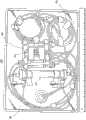
图8示出紧凑歧管在便携透析系统中的安装;Figure 8 shows the installation of a compact manifold in a portable dialysis system;
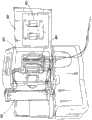
图9示出具有成功安装的歧管的便携透析系统的另一个视图;Figure 9 shows another view of the portable dialysis system with a successfully installed manifold;
图10是示出在透析模式中的本发明的一个实施例的示意性图形;和Figure 10 is a schematic diagram illustrating an embodiment of the invention in dialysis mode; and
图11是示出在透析充灌模式中的本发明的一个实施例的示意性图形。Figure 11 is a schematic diagram illustrating an embodiment of the present invention in a dialysis prime mode.
具体实施方式Detailed ways
尽管本发明可以以许多不同形式进行实施,但是为了便于理解本发明的原理,现参照在附图中示出的实施例并且特定的语言将用于描述所述实施例。然而,应当理解,并不打算因此限制本发明的范围。本发明所涉及的技术领域的技术人员通常能够想到的在描述的实施例中的任何变化和进一步修改以及如在此描述的本发明的原理的任何的进一步应用。While the invention may be embodied in many different forms, to facilitate an understanding of the principles of the invention, reference is now made to the embodiments illustrated in the drawings and specific language will be used to describe the same. It should be understood, however, that no limitation of the scope of the invention is thereby intended. Any changes and further modifications in the described embodiments and any further applications of the principles of the invention as described herein will normally occur to those skilled in the art to which the invention pertains.
“治疗”、“处理”及其变体是指与病情相关的一个或多个症状或者体症的程度、频率或者严重性的任何降低。"Treatment," "treatment," and variations thereof refer to any reduction in the degree, frequency, or severity of one or more symptoms or signs associated with a condition.
“持续时间”及其变体是指从开始到结束的规定治疗的时间段,不管治疗是否因为病情治愈而结束或者治疗由于任何原因而中止。在治疗的持续时间中,可以规定多个治疗疗程,在所述疗程中对对象执行一个或多个规定的刺激。"Duration" and its variants mean the period of time from start to finish of prescribed treatment, regardless of whether treatment ends due to cure of the condition or treatment is discontinued for any reason. Over the duration of the treatment, a number of treatment sessions may be prescribed in which one or more prescribed stimuli are administered to the subject.
“疗程”是指作为规定的治疗计划的一部分对对象执行一剂刺激的时间。A "session" refers to the period of time for which a dose of stimulation is administered to a subject as part of a prescribed treatment plan.
术语“和/或”是指所列要素的一个或者全部,或者所列要素的任何两个或多个的组合。The term "and/or" refers to one or all of the listed elements, or a combination of any two or more of the listed elements.
术语“包括”及其变体在出现在说明书和权利要求中的情形下并不具有限制的含义。The terms "comprises" and variations thereof do not have a limiting meaning where they appear in the description and claims.
除非另有特别说明,“一”、“所述”、“一个或多个”和“至少一个”是可互换使用的并且指一个或超过一个。Unless specifically stated otherwise, "a", "the", "one or more" and "at least one" are used interchangeably and mean one or more than one.
对于包括离散的步骤的在这里公开的任何的方法,所述步骤可以以任何可行的顺序执行。并且,根据需要,两个或多个步骤的任何组合可以同时执行。For any method disclosed herein comprising discrete steps, the steps may be performed in any order feasible. Also, any combination of two or more steps can be performed simultaneously, as desired.
同样地,在这里,通过端点的数值范围的引用包括包含在该范围内的所有数字(例如,1至5包括1、1.5、2、2.75、3、3.80、4、5等)。除非另有特别说明,在说明书和权利要求中使用的表示部件数量、分子重量等的所有数字应当理解为在所有情形下都可以被术语“大约”修饰。相应地,除非另有相反说明,在说明书和权利要求中提出的数字参数都是近似值,其可以取决于本发明寻求获得的期望属性而变化。最起码,并且不是试图限制权利要求的范围的等同原则,每个数字参数应当至少根据所代表的明显的位数以及进行普通的取整技术进行理解。Also herein, the recitations of numerical ranges by endpoints include all numbers subsumed within that range (eg, 1 to 5 includes 1, 1.5, 2, 2.75, 3, 3.80, 4, 5, etc.). Unless specifically stated otherwise, all numbers expressing numbers of parts, molecular weights, etc. used in the specification and claims are to be understood as being modified in all instances by the term "about". Accordingly, unless indicated to the contrary, the numerical parameters set forth in the specification and claims are approximations that can vary depending upon the desired attributes sought to be obtained by the present invention. At the very least, and not as an attempt to limit the doctrine of equivalents to the scope of the claims, each numerical parameter should at least be construed in light of the significant number of digits represented and by applying ordinary rounding techniques.
尽管阐明本发明的宽的范围的数值范围和参数是近似值,但是在特定例子中提出的数字值被尽可能精确地汇报。但是,全部的数字值固有地包含在它们的各测试测量中发现的标准偏差所导致的必要的一定范围。Notwithstanding that the numerical ranges and parameters setting forth the broad scope of the invention are approximations, the numerical values set forth in the specific examples are reported as precisely as possible. All numerical values, however, inherently contain certain ranges necessarily resulting from the standard deviation found in their respective testing measurements.
本发明消除了对具有消过毒的盐水的单独的包以及它的相关硬件的需要。在一个实施例中,本发明采用吸附剂产生的透析液,其在当回路的透析液侧被充灌时产生,作为用于血液侧的充灌流体。为了解释本发明的目的,本发明的充灌方法和系统中的示例性歧管将首先被描述。The present invention eliminates the need for a separate bag with sterile saline and its associated hardware. In one embodiment, the present invention employs sorbent generated dialysate, which is generated when the dialysate side of the circuit is filled, as the fill fluid for the blood side. For purposes of explaining the present invention, an exemplary manifold in the filling method and system of the present invention will first be described.
图1示出用于体外血液处理系统100的流体回路,其用于进行血液透析和血液过滤。在本发明的一个实施例中,系统100实施为便携人工肾(PAK),其可以由患者使用来在家里进行透析。FIG. 1 shows a fluid circuit for an extracorporeal blood treatment system 100 for performing hemodialysis and hemofiltration. In one embodiment of the invention, the system 100 is implemented as a Portable Artificial Kidney (PAK) that can be used by a patient to perform dialysis at home.
参照图1,血液透析系统包括两个回路-血液回路101和透析液回路102。在透析过程中的血液治疗通过具有半透膜的交换器-血液透析器或者透析器103引入体外循环。患者的血液在膜(透析器)103的一侧上在血液回路101中循环,称作透析液的透析液体,其包括由医师规定浓度的血液的主电解液,在透析液回路102另侧上循环。这样,透析液流体的循环提供用于血液中的电解浓度的调整和调节。Referring to FIG. 1 , the hemodialysis system comprises two circuits - a blood circuit 101 and a dialysate circuit 102 . The blood therapy during dialysis is introduced into the extracorporeal circulation via an exchanger with a semipermeable membrane—the hemodialyzer or dialyzer 103 . The patient's blood circulates in the blood circuit 101 on one side of the membrane (dialyzer) 103 , a dialysate fluid called dialysate, which includes the blood's main electrolyte in a concentration prescribed by the physician, and on the other side of the dialysate circuit 102 cycle. In this way, the circulation of the dialysate fluid provides for adjustment and regulation of the concentration of electrolytes in the blood.
在血液回路101中馈送不纯的血液到透析器103的来自患者的线路104设置有梗塞检测器105,其整体地连接到目视或者音响警报(未示出)以发出对血液流动的任何阻塞的信号。为了防止血液凝结,用于注射抗凝剂例如肝素到血液中的装置106,例如泵、注射器或者任何其它的注射装置,同样被提供。还提供蠕动泵107以保证血液在正常(期望)方向的流动。The line 104 from the patient that feeds impure blood to the dialyzer 103 in the blood circuit 101 is provided with an infarction detector 105 integrally connected to a visual or audible alarm (not shown) to signal any obstruction to blood flow signal of. In order to prevent blood clotting, means 106 for injecting an anticoagulant such as heparin into the blood, such as a pump, a syringe or any other injection means, are also provided. A peristaltic pump 107 is also provided to ensure blood flow in the normal (desired) direction.
压力传感器108设置在不纯的血液进入透析器103的入口处。其它压力传感器109、110、111和112设置在血液透析系统的各个位置,其帮助跟踪和保持在优势点的流体压力。The pressure sensor 108 is arranged at the inlet of the impure blood into the dialyzer 103 . Other pressure sensors 109, 110, 111 and 112 are placed at various locations in the hemodialysis system which help to track and maintain the fluid pressure at the vantage point.
在来自透析器103的使用过的透析液流体进入透析液回路102的点上,血液泄漏传感器113被提供以传感和警告到透析液回路中的任何血细胞泄漏。一对旁通阀114同样提供在透析液回路的起点和终点,以使得在起动情形下,或者操作者认为需要的其它情形下,透析器可以由透析液流体流动绕过,但是流动仍得以维持。另一个阀115正好设置在充灌/排出端口116之前。端口116用于通过透析液溶液初始充注回路,并在透析后以及在一些情形下在透析过程中移除使用过的透析液流体。在透析过程中,阀115可以用于通过再次补充适当浓度的流体而更换掉用过的例如高浓度的钠透析液的一部分,以使得透析液的总的组分浓度保持在期望水平。At the point where used dialysate fluid from the dialyzer 103 enters the dialysate circuit 102, a blood leak sensor 113 is provided to sense and warn of any blood cell leak into the dialysate circuit. A pair of bypass valves 114 are also provided at the beginning and end of the dialysate circuit so that in a start-up situation, or other situations the operator deems necessary, the dialyzer may be bypassed by dialysate fluid flow, but flow is still maintained . Another valve 115 is provided just before the fill/drain port 116 . Port 116 is used to initially fill the circuit with dialysate solution and to remove used dialysate fluid after dialysis and, in some cases, during dialysis. During dialysis, valve 115 can be used to replace a portion of the used, eg high concentration sodium dialysate, by resupplying with fluid of the appropriate concentration so that the overall component concentration of the dialysate remains at the desired level.
透析液回路设置有两个蠕动泵117和118。泵117用于泵送透析液流体到排出或者废物容器,以及用于泵送再生的透析液到透析器103中。泵118用于从透析器103泵送出用过的透析液,并通过吸附剂119对其施压,以及用于泵送入来自端口116的透析流体,用于充填系统或者维持透析液中的组分浓度。The dialysate circuit is provided with two peristaltic pumps 117 and 118 . Pump 117 is used to pump dialysate fluid to a drain or waste container, and to pump regenerated dialysate into dialyzer 103 . Pump 118 is used to pump spent dialysate from dialyzer 103 and pressurize it through sorbent 119, and to pump dialysate fluid from port 116 for priming the system or maintaining the dialysate in the dialysate. component concentration.
吸附剂类型的盒119设置在透析液回路中,其包含数层材料,每层具有移除杂质例如尿素和肌氨酸酐的特定作用。这些材料的组合允许适于饮用的水充入到系统中,用作透析液流体。还允许闭合环透析。也就是,吸附剂盒使得能够从来自透析器的用过的透析液再生新的透析液。对于新的透析液流体,适当容量例如0.5、1、5、8或者10公升的衬里容器或者储存器120被提供。A cartridge 119 of sorbent type is provided in the dialysate circuit, comprising several layers of material, each layer having a specific role in removing impurities such as urea and creatinine. The combination of these materials allows potable water to be filled into the system for use as the dialysate fluid. Closed loop dialysis is also allowed. That is, the sorbent cartridge enables regeneration of new dialysate from spent dialysate from the dialyzer. For fresh dialysate fluid, a lined container or reservoir 120 of appropriate capacity, eg 0.5, 1, 5, 8 or 10 liters, is provided.
取决于基于医师处方的患者要求,期望量的注入液溶液121可以加入到透析流体中。注入液121是包含矿物质和/或葡萄糖的溶液,其帮助在吸附剂进行的不期望的移除之后补充透析液流体中的例如钾和钙的矿物质到适当水平。提供蠕动泵122以泵送期望量的注入液溶液到容器120。照相机123可以任选地提供来监测注入液的不断改变的液位,作为注入液流动失效的安全检查警告。Depending on the patient's requirements based on a physician's prescription, a desired amount of infusate solution 121 may be added to the dialysis fluid. Infusate 121 is a solution containing minerals and/or glucose that helps replenish minerals such as potassium and calcium in the dialysate fluid to appropriate levels after undesired removal by the sorbent. A peristaltic pump 122 is provided to pump the desired volume of infusate solution to container 120 . A camera 123 may optionally be provided to monitor the changing level of the infusate as a safety check warning of infusate flow failure.
提供加热器124以保持容器120中的透析液流体的温度在要求的水平。透析液流体的温度可以由正好位于流体进入透析器的入口之前的温度传感器125进行传感。容器120同样装备有:刻度尺126,用于跟踪容器中流体的重量以及由此的体积;以及电导传感器127,其显示透析液流体的电导率。电导传感器127提供透析液中钠水平的指示。A heater 124 is provided to maintain the temperature of the dialysate fluid in container 120 at a desired level. The temperature of the dialysate fluid may be sensed by a temperature sensor 125 located just before the inlet of the fluid into the dialyzer. The container 120 is also equipped with a scale 126 for tracking the weight and thus volume of fluid in the container, and a conductivity sensor 127 which displays the conductivity of the dialysate fluid. Conductivity sensor 127 provides an indication of the sodium level in the dialysate.
在来自患者的血液进入到用于透析的系统之前,提供医疗端口129。在来自透析器的清洁的血液返回到患者之前提供另一医疗端口130。空气(或者气泡)传感器131和弹簧夹132用于回路中以检测和防止任何空气、其它或者气泡返回到患者。A medical port 129 is provided before blood from the patient enters the system for dialysis. Another medical port 130 is provided before the cleaned blood from the dialyzer is returned to the patient. An air (or air bubble) sensor 131 and spring clip 132 are used in the circuit to detect and prevent any air, other or air bubbles from returning to the patient.
充灌装置133附连到血液透析系统,其通过在其用于透析之前用消毒盐水充注血液回路而帮助准备该系统。充灌装置可包括具有IV袋钉或者IV针或者预附连的二者的组合的短管部分。A priming device 133 is attached to the hemodialysis system which helps prepare the system by priming the blood circuit with sterile saline before it is used for dialysis. The inflation set may include a stub section with IV bag staples or IV needles or a combination of both pre-attached.
本领域技术人员从上面关于用于血液透析的流体回路的讨论可以得出,血液透析和/或血液过滤系统是一种复杂的系统并包括数个元件。如果以传统的方式实施,该系统将呈现为管网,并且对于家庭透析用户来说配置和使用过于复杂。Those skilled in the art will appreciate from the above discussion regarding fluid circuits for hemodialysis that a hemodialysis and/or hemofiltration system is a complex system and includes several components. If implemented in a traditional manner, the system would appear as a pipe network and would be too complex to configure and use for home dialysis users.
因此,为了制造简单且易于患者在家中使用的系统,本发明实施系统为紧凑的歧管,其中如图1所示的流体回路的大部分部件集成为一件模制塑料或者配置为连接在一起以形成单一的操作歧管结构的多件模制塑料。Therefore, in order to make a system that is simple and easy for a patient to use at home, the present invention embodies the system as a compact manifold in which most of the components of the fluid circuit as shown in Figure 1 are integrated into one piece of molded plastic or configured to connect together Multiple pieces of molded plastic to form a single operating manifold structure.
图2示出根据本发明的一个实施例的紧凑歧管的结构元件。一次性歧管泵送和导向流体流动,同时测量关键区域的压力。这些流体包括血液、透析液、注入液和抗凝剂。此外,歧管提供用于检测血液从透析器泄露的特征、用于检测动脉线路中的梗塞的特征和用于检测静脉线路中的空气的特征。Figure 2 shows the structural elements of a compact manifold according to one embodiment of the invention. Disposable manifolds pump and direct fluid flow while measuring pressure in critical areas. These fluids include blood, dialysate, infusate, and anticoagulants. Additionally, the manifold provides features for detecting blood leaks from the dialyzer, features for detecting infarctions in the arterial line, and features for detecting air in the venous line.
参照图2,在一个实施例中,紧凑歧管200包括具有固定地附连在那里的部件的多个塑料层。更具体地,歧管200包括以下元件:Referring to FIG. 2 , in one embodiment, a
后盖201
压力传感器膜202
阀膜203
中间主体204
前盖205
泵管部分(图2中未示出)Pump tubing section (not shown in Figure 2)
中间主体层204模制包含在一侧上的通道中。这些通道借助包括超声波焊接的许多方法通过固定地附着到中间主体的前盖层实现。该组合的前盖-中间主体结构形成歧管内的流体通路的主要部分。在中间主体204的相对侧上具有形成用于阀和压力传感的表面的特征,其连通到歧管前盖侧面上的流体通路。歧管包括用于阀和压力传感的弹性部件。这些弹性部件通过利用超声波焊接而收纳在后盖层和中间主体层之间,并且实现遍及歧管的流体通路。The
参照图2,在一个实施例中,歧管200包括五个压力传感器膜202和三到四个用于双路阀的膜203。在一个实施例中,两个盖201和205以及歧管200的中间主体204由聚碳酸酯材料或者ABS(丙烯腈丁二烯苯乙烯)模制而成。压力传感器膜202和阀膜203由普通材料例如Santoprene,或者更优选地Sarlink,模制而成,所述材料为医学级弹性聚合物。在一个实施例中,前盖和后盖205和201可以由光学透明材料,至少对某些预选波长的光透明的材料,模制而成,以允许对包含在里面的流体进行光谱分析。Referring to FIG. 2 , in one embodiment, a manifold 200 includes five
此外,该歧管优选地包括四个泵送部件。这些泵送部件是挤压成型的PVC管子的部分,其形成为并且尺度适合以具有优化用于泵用途,特别是滚子泵用途的属性。该管子接合到具有倒钩的配置,所述配置一体模制到歧管中间主体。四个泵送部件的一个用于从患者的动脉抽取血液并将其泵送通过透析器以及回到患者的静脉。两个泵送部件是用于透析液流动,以及一个是用于将注入液递送到透析液流体回路。单独的注射器泵可以用于在透析器之前泵送抗凝血剂到动脉血液通路中。Furthermore, the manifold preferably includes four pumping components. These pumping components are sections of extruded PVC pipe formed and dimensioned to have properties optimized for pump use, particularly roller pump use. The tube is joined to a barbed configuration integrally molded to the manifold intermediate body. One of the four pumping components is used to draw blood from the patient's artery and pump it through the dialyzer and back into the patient's vein. Two pumping components are for dialysate flow and one is for infusate delivery to the dialysate fluid circuit. A separate syringe pump can be used to pump anticoagulant into the arterial blood access prior to the dialyzer.
在一个实施例中,歧管进一步包括管子端口,优选地是在10-14个的范围,更优选12个端口,用于连接歧管内的所有流体通路到包括透析器、吸附剂盒、袋储存器、注入液容器、患者血液线路、抗凝血剂、传感器、充灌线路和排出线路的一次性装置中的其它的部件,如下面进一步讨论的。In one embodiment, the manifold further comprises tubing ports, preferably in the range of 10-14, more preferably 12 ports, for connecting all fluid pathways within the manifold to include dialyzers, sorbent cartridges, bag storage Other components in the disposable set include an insulator, infusate container, patient blood line, anticoagulant, sensor, fill line, and drain line, as discussed further below.
在一个实施例中,歧管成形为大写的“I”,具有彼此平行的第一部分和第二部分以及连接部分,该连接部分a)垂直于第一部分和第二部分,并且b)用于连接第一和第二部分。在一个实施例中,连接部分连接第一部分的中央到第二部分的中央,从而使得连接部分和第一和第二部分的每个末端之间的距离为等距离的。应当认识到,连接部分可以布置在第一和第二部分的末端上,从而形成大写的“C”或者向后的“C”。歧管还可以相对于透析系统旋转,并且不必定位为大写的“I”,例如,它可以定位在它的侧面上或者成一定角度。如图3b所示,在示例性实施例中,歧管具有以下尺度:L1和L2是在4-7英寸范围内,优选大约5.7英寸,L3和L4是在0.5-1.5英寸范围内,优选大约1英寸,L5是在2.5-4.5英寸的范围,优选大约3.5英寸,L6是在1-3英寸的范围内,优选大约1.8英寸。尽管已经提供了上述尺度,但是应当认识到,在此公开的本发明并不限于任何特定尺度或者尺度的组合。In one embodiment, the manifold is shaped as a capital "I" with first and second sections parallel to each other and a connecting section a) perpendicular to the first and second sections and b) for connecting First and second part. In one embodiment, the connecting portion connects the center of the first portion to the center of the second portion such that the distance between the connecting portion and each end of the first and second portions is equidistant. It should be appreciated that the connecting portion may be disposed on the ends of the first and second portions, forming a capital "C" or a backward "C". The manifold can also be rotated relative to the dialysis system and does not have to be positioned as a capital "I", for example it could be positioned on its side or at an angle. As shown in Figure 3b, in an exemplary embodiment, the manifold has the following dimensions: L1 and L2 are in the range of 4-7 inches, preferably about 5.7 inches, and L3 and L4 are in the range of 0.5-1.5 inches, preferably about 1 inch, L5 is in the range of 2.5-4.5 inches, preferably about 3.5 inches, and L6 is in the range of 1-3 inches, preferably about 1.8 inches. While the above dimensions have been provided, it should be appreciated that the invention disclosed herein is not limited to any particular dimension or combination of dimensions.
在一个实施例中,歧管200的装配工艺包括配合后盖201到中间主体204,同时通过使得膜的第一侧面物理地附着或者接触中间主体以及使得膜的第二侧面通过后盖201中的孔、空间或者空穴211而将膜202和203贴附就位。优选地,膜的第二侧面具有层级结构,其允许第一层级通过空穴211,而第二层级保留在后盖201和中间主体204之间。这贴附膜202、203到后盖201中。而且,优选地,中间主体204包含凹陷,膜202、203的第一侧面位于该凹陷中,从而将它们贴附到中间主体204。在替代的构型中,膜202和203可以以多射击模制工艺共模制到后盖201。In one embodiment, the assembly process of the manifold 200 includes mating the
本领域技术人员将认识到,歧管的各个部件可以利用任何适当的装置边界接合或者固定在一起。在一些实施例中,中间主体和后盖之间的密封经由超声波焊接或者胶粘剂实现。替代地,可以采用激光焊接。前盖以类似的方式接合到中间主体的另一侧面。在一个实施例中泵管子部分溶剂接合就位,或者在替代实施例中,可以利用塑料中的吸收激光的添加剂对所述部分进行激光焊接。Those skilled in the art will recognize that the various components of the manifold may be bounded or secured together by any suitable means. In some embodiments, the seal between the intermediate body and the back cover is achieved via ultrasonic welding or adhesives. Alternatively, laser welding may be used. The front cover is joined to the other side of the central body in a similar manner. In one embodiment the pump tubing sections are solvent bonded in place, or in an alternative embodiment the sections may be laser welded with a laser absorbing additive in the plastic.
在一个实施例中,前盖由透明的并且将提供对流体通路的可见性的BASF Terlux 2802HD,ABS模制而成。ABS的透明性同样提供一种用于检查超声波焊接的表面的完整性的手段。ABS由于其生物相容性以及对超声波焊接的兼容性而是优选的。此外,前盖可以包括模制在里面的纹理表面以帮助促进前盖和中间主体之间更好地接合。该纹理表面是一种本领域技术人员知晓的化学蚀刻工艺。一个优选的纹理深度为.0045”。其它适当的纹理也可以是激光蚀刻的。待焊接在前盖上的表面设计为具有.003”的凹陷,其转换为在模具上的.003”的升高表面。这提供精确的表面以接收纹理。一旦在模具上产生纹理,该.003”表面的高度降低。因为.0045”纹理深度的峰和谷,可以假定,平均值将是所述数量的一半或者.00225”。该结果将使得模具处于.00075”的钢安全条件中。In one embodiment, the front cover is molded from BASF Terlux 2802HD, ABS which is transparent and will provide visibility to the fluid pathways. The transparency of ABS also provides a means for inspecting the integrity of the ultrasonically welded surface. ABS is preferred due to its biocompatibility and compatibility with ultrasonic welding. Additionally, the front cover may include a molded-in textured surface to help promote better engagement between the front cover and the intermediate body. The textured surface is a chemical etching process known to those skilled in the art. A preferred texture depth is .0045". Other suitable textures can also be laser etched. The surface to be welded on the front cover is designed to have a .003" depression which translates to a .003" rise on the die High Surface. This provides a precise surface to receive the texture. Once the texture is created on the mold, the height of this .003" surface is reduced. Because of the peaks and valleys of the .0045" texture depth, it can be assumed that the average will be half that amount or .00225". This result will place the mold in a steel safe condition of .00075".
在一个实施例中,前盖提供动脉和静脉通路中的血流导向器。这些特征设计来最小化溶血。血流导向器提供用于整个通路中的始终如一的横截面积并最小化如果没有导向器的存在血液将接触到的锋利边缘。在血流导向器的相对侧面上的壁已经被用于提供模制塑料部分中的更加均一的壁厚度。这将防止在这个区域的沉孔,而沉孔会影响周围的焊接表面。在一个实施例中,前盖壁厚度是.075”。In one embodiment, the front cover provides a flow director in the arterial and venous access. These features are designed to minimize hemolysis. The blood flow director provides for a consistent cross-sectional area throughout the pathway and minimizes sharp edges that blood would come into contact with if the director were not present. Walls on opposite sides of the blood flow director have been used to provide a more uniform wall thickness in the molded plastic part. This will prevent countersinking in this area, which would affect the surrounding soldering surface. In one embodiment, the front cover wall thickness is .075".
任选地,前盖具有用于组装目的而设置的对齐孔,以保证在超声波焊接工艺过程中前盖和中间主体的精确对齐。对齐孔周围的升高的凸出部有助于最大化与焊接装置的对齐销的接触以使得塑料不会由于摩擦而容易地熔化。这些凸出部并不接触中间主体并且不焊接到中间主体以保证孔是特定的(patent)。Optionally, the front cover has alignment holes provided for assembly purposes to ensure precise alignment of the front cover and intermediate body during the ultrasonic welding process. The raised protrusions around the alignment holes help maximize contact with the alignment pins of the welding device so that the plastic does not melt easily due to friction. These protrusions do not touch the intermediate body and are not welded to the intermediate body to ensure that the holes are patented.
图3a提供本发明的紧凑歧管的中间主体部件的透视图。如图3所示,血液透析/血液过滤系统的整个血液和透析液流动路径301模制到中间主体中。用于血液提纯系统的各个功能元件302例如泵、阀和传感器的容纳器集成到紧凑歧管的中间主体部分中。Figure 3a provides a perspective view of the intermediate body component of the compact manifold of the present invention. As shown in Figure 3, the entire blood and dialysate flow path 301 of the hemodialysis/hemofiltration system is molded into the intermediate body. Receptacles for the various functional elements 302 of the blood purification system such as pumps, valves and sensors are integrated into the central body portion of the compact manifold.
中间主体可以由BASF Terlux 2802HD,ABS模制而成。另一替代的ABS是Lustran 348,White。ABS由于其生物相容性以及对超声波焊接的兼容性而被选取。中间主体连同前盖提供用于歧管的流体路径通道。中间主体包含用于对接接头类型的超声波焊接的能量导引器。在一个实施例中,能量导引器的尺度为.019”高、.024”宽的底座。这产生.00023平方英寸的横截面积。焊接表面的宽度为.075”,从而产生大约.003”x.075”的焊接体积。对接接头类型的能量导引器由于其简单性以及能够控制模制部分的几何尺寸而比其它类型例如剪切接头、舌部和凹槽、阶梯接合,更为优选。通风孔设置在焊接几何结构中以防止俘获的气体强迫地通过焊接处,从而产生会导致泄漏的劣质的焊接。The middle body can be molded from BASF Terlux 2802HD, ABS. Another alternative ABS is Lustran 348, White. ABS was chosen for its biocompatibility and compatibility with ultrasonic welding. The intermediate body, together with the front cover, provides fluid path access for the manifold. The intermediate body contains energy directors for butt joint type ultrasonic welding. In one embodiment, the energy director measures .019" high by .024" wide base. This yields a cross-sectional area of .00023 square inches. The width of the weld surface is .075", resulting in a weld volume of approximately .003" x .075". Butt joint style energy directors are superior to other types such as shears due to their simplicity and ability to control molded part geometry. Cut joints, tongue and groove, stepped joints, are more preferred.Vent holes are provided in the weld geometry to prevent trapped gases from being forced through the weld, creating poor quality welds that would cause leaks.
中间主体的后盖侧优选地提供模制在里面的纹理表面以帮助促进后盖和中间主体之间的更好的接合。该纹理表面是本领域技术人员知晓的化学蚀刻工艺。优选的纹理深度为.0045”。其它的适当的纹理也可以是激光蚀刻。待焊接在中间主体上的表面设计有.003”的凹陷,其转换为模具上的.003”的升高表面。一旦在模具上产生纹理,该.003”表面的高度降低,因为.0045”纹理深度的峰和谷,所以可假定的是,平均值为该数量的一半,或者.00225”。该结果使得模具处于.00075”的钢安全条件中。The back cover side of the center body preferably provides a molded-in textured surface to help promote better engagement between the back cover and center body. The textured surface is a chemical etching process known to those skilled in the art. The preferred texture depth is .0045". Other suitable textures may also be laser etched. The surface to be welded on the intermediate body is designed with a .003" depression which translates to a .003" raised surface on the mold. Once the texture is produced on the mold, the height of the .003" surface is reduced because of the peaks and valleys of the texture depth at .0045", so it can be assumed that the average is half that amount, or .00225". This result puts the mold in a steel safe condition of .00075".
待焊接的模具的尺度会对超声波焊接工艺的成功具有主要影响。表面积越大,焊接工艺越困难。重要的是,精确控制焊接表面。在前盖和后盖中的均一厚度比平面度更为重要,因为在焊接工艺过程中,平面度稍微偏离的盖子将被挤压为平的。在中间主体上的平面度由于防止它在焊接工艺过程中变平的结构设计而是重要的。由于这些问题,非常重要的是,这些部分正确地设计并且不会趋于变形,例如翘曲、下沉,尺寸变化等。此外,模具结构和质量需要达到所述部分需要满足的高标准。相应地,模制工艺控制也将要求最高的标准。The dimensions of the mold to be welded can have a major impact on the success of the ultrasonic welding process. The larger the surface area, the more difficult the welding process. It is important to precisely control the weld surface. Uniform thickness in the front and back covers is more important than flatness because covers that deviate slightly from flatness will be extruded flat during the welding process. Flatness on the intermediate body is important due to the structural design preventing it from flattening during the welding process. Because of these issues, it is very important that these parts are properly designed and do not tend to deform, such as warping, sinking, dimensional changes, etc. In addition, mold construction and quality need to meet the high standards that the part needs to meet. Correspondingly, molding process control will also demand the highest standards.
后盖可以由BASF Terlux 2802HD,ABS模制。后盖包含用于对接接头类型的超声波焊接的能量导引器。能量导引器的尺度是.019”高、.024”宽的底座。这导致.00023平方英寸的横截面积。焊接表面的宽度是.075”,从而产生大约.003”x.075”的焊接体积。该.003”焊接体积在当确定组装的部件的几何结构是应当考虑。通风孔设置在焊接几何结构中以防止俘获的气体强迫地通过焊接处,从而产生会导致泄漏的劣质的焊接。在后盖中的对齐孔被提供用于组装目的以保证在超声波焊接工艺过程中后盖精确对齐中间主体。在后盖中的对齐孔还提供在正确装载时歧管和仪器的精确对齐。对齐孔周围的升高的凸出部设计来最大化与焊接夹具的对齐销的接触,以使得塑料不会由于摩擦而轻易地熔化。这些凸出部并不接触并且不焊接以保证孔是特定的。The back cover can be molded from BASF Terlux 2802HD, ABS. The back cover contains the energy director for ultrasonic welding of the butt joint type. The Energy Director measures .019" high by .024" wide base. This results in a cross-sectional area of .00023 square inches. The width of the weld surface is .075", resulting in a weld volume of approximately .003"x.075". This .003" weld volume should be considered when determining the geometry of the assembled parts. Vents are provided in the weld geometry to prevent trapped gases from being forced through the weld, creating a poor quality weld that would lead to leaks. Alignment holes in the back cover are provided for assembly purposes to ensure accurate alignment of the back cover with the middle body during the ultrasonic welding process. Alignment holes in the back cover also provide precise alignment of the manifold and instruments when properly loaded. The raised tabs around the alignment holes are designed to maximize contact with the alignment pins of the welding jig so that the plastic does not melt easily due to friction. These protrusions do not touch and are not welded to ensure that the holes are specific.
超声波焊接由于其制造工艺的低成本而作为用于接合歧管三个主要部件的方法而被选取。产生焊接属性的相对低的设备成本和周期时间导致这种更低的制造成本。一旦各个部分装载到固定设备中,具有操纵杆的移动和移除的焊接周期可以在几秒内完成。实际的焊接时间为大约一秒。其它接合方法包括热板、激光器和UV胶粘剂。Ultrasonic welding was chosen as the method for joining the three main components of the manifold due to the low cost of its manufacturing process. Relatively low equipment costs and cycle times to produce welded properties lead to this lower manufacturing cost. Once the individual parts are loaded into the fixture, the welding cycle with movement and removal of the joystick can be completed in seconds. The actual welding time is about one second. Other joining methods include hot plates, lasers, and UV adhesives.
参照图3a,在一个实施例中,中间主体部分300在其中集成有三个双路阀307、五个压力传感器306、一个梗塞检测器、一个气泡检测器和一个血液泄漏检测器。本领域技术人员将认识到,集成到中间主体部分300中的功能部件的数量和类型可以根据血液提纯系统的要求和应用而改变,因此可以包括1、2、3、4、6、7、8、9、10或者更多压力传感器,1、2、4、5、6或者更多的双路阀,0、2、3、4或者更多的梗塞检测器,0、2、3、4或者更多的气泡检测器,0、2、3、4或者更多血液泄漏检测器。此外,中间主体部分300包括多个端口303、304。Referring to Figure 3a, in one embodiment, the
端口包括内部端口304,流体经由泵部分(未示出)从歧管300的第一和第二部分和在第一和第二部分之间流动通过内部端口304。在一个实施例中,第一部分具有四个内部端口304,在第一部分和连接部分连接的点的每个侧面上分别两个端口。应当认识到,第一部分可以具有1、2、3、5、6、7或者更多的内部端口。在一个实施例中,第二部分具有四个内部端口304,在第一部分和连接部分连接的点的每个侧面上分别两个。应当认识到,第二部分可以具有1、2、3、5、6、7或者更多的内部端口。此外,优选地,第一部分的内部端口的位置和定位与第二部分的内部端口的位置和定位镜像对称。端口还包括到歧管300外部的元件的外部端口303。在一个实施例中,第一部分具有两个外部端口303。在一个实施例中,第二部分具有十个外部端口304。在一个实施例中,第一部分具有1、3、4、5、6、7、8、9、10、11、12、13、14、15或者更多的外部端口303。在一个实施例中,第二部分具有1、2、3、4、5、6、7、8、9、11、12、13、14、15或者更多的外部端口304。The ports include an internal port 304 through which fluid flows from and between the first and second sections of the manifold 300 via a pump section (not shown). In one embodiment, the first part has four internal ports 304, two ports on each side of the point where the first part and the connecting part connect. It should be appreciated that the first part may have 1, 2, 3, 5, 6, 7 or more internal ports. In one embodiment, the second part has four internal ports 304, two on each side of the point where the first part and the connecting part connect. It should be appreciated that the second part may have 1, 2, 3, 5, 6, 7 or more internal ports. Furthermore, preferably, the position and positioning of the internal ports of the first part are mirror-symmetrical to the position and positioning of the internal ports of the second part. Ports also include external ports 303 to components external to
结合流体接触元件到歧管中,如上所述,使得能够设计这样系统:其中可再用的传感器安装在歧管配合到其上的透析设备中,而必要的一次性流体接触元件分离开并布置在歧管中,如上所述。为了保证正确的读数和测量,流体接触元件和可再用的传感器需要对齐。歧管和透析设备之间的配合和对齐关于定位和施加压力是关键的。典型地,这样的配合精度必须提供在X、Y和Z方向.001”-.010”的容差并施加在10-100PSI的安装力以通过歧管抵抗流体力。这样的关键的定位通过在歧管上的特定设计的定位表面实现,所述定位表面与透析设备上的互补定位表面对准。要求的力通过透析设备结构的分析和设计而被递送以允许在操作过程中在歧管内形成的全部流体和机械压力下X和Y位置和Z方向偏转小于大约.001”-.010”。因为歧管包含在一个整块的基板上的许多结构,这样的关键对齐仅需要一旦用于定位歧管的全部的特征以及透析设备的全部的配合特征时完成。Incorporating the fluid contact elements into the manifold, as described above, enables the design of systems in which the reusable sensors are installed in the dialysis device onto which the manifold fits, while the necessary disposable fluid contact elements are separated and arranged In the manifold, as above. To ensure correct readings and measurements, the fluid contact elements and reusable sensors need to be aligned. The fit and alignment between the manifold and the dialysis device is critical with regard to positioning and applying pressure. Typically, such fit accuracy must provide tolerances of .001"-.010" in the X, Y, and Z directions and apply an installation force of 10-100 PSI to resist fluid forces through the manifold. Such critical positioning is achieved by specially designed positioning surfaces on the manifold that align with complementary positioning surfaces on the dialysis device. The required forces are delivered through analysis and design of the dialysis device structure to allow X and Y positional and Z deflection of less than about .001"-.010" under all fluid and mechanical pressures developed within the manifold during operation. Because the manifold contains many structures on one monolithic substrate, such critical alignment only needs to be done once for positioning all of the features of the manifold and all of the mating features of the dialysis device.
参照图9,在一个实施例中,歧管902安装在透析系统901的竖直前面板903上。歧管通过多个对齐机构准确定位在该面板903上。第一对齐机构包括多个在面板903中的对齐销,其接合歧管902中的对齐孔。第二对齐机构包括至少一个锁闩,其保持歧管903在特定的安装位置,直到门906闭合并且最终的精确位置得以获得。在一个实施例中,歧管的后盖在顶部和底部具有两个设计在其中的凸片。这些凸片在门闭合以及随后布置歧管的精确位置之前锁闩歧管在第一保持位置。凸片使得锁扣机构能够手动释放或者通过球体制动器释放,所述球体制动器要求用手强迫地移除歧管。在另一个实施例中,锁闩机构包括在后盖顶部上的弹簧加载的插入和释放机构。该机构具有在顶部锁闩和底部锁闩之间的连杆。当在顶部的释放机构被促动时,底部锁闩也释放。Referring to FIG. 9 , in one embodiment, a manifold 902 is mounted on a vertical
第三对齐机构包括外形导引器908,其导向歧管902的整体位置和构型。外形导引器908优选地成形为与歧管902的物理结构配合、匹配或者否则互补。在一个实施例中,导引器908总体为矩形并配置来配合在由第一部分、第二部分和连接部分的侧面界定的空间内部。第四对齐机构包括门906,其具有至少一个弹簧装载压力板905,该板905将歧管902保持在门906和前面板903之间,从而施加用于阀和压力传感的足够压力。门906还包括四个压力靴,其施加足够压力到泵送部件用于流体的旋转蠕动递送。应当认识到,可以使用单独或者组合一个或多个对齐机构,以实现必要的对齐和用于歧管的受压位置。应当进一步认识到,对齐机构附连到透析装置壳体内的凹陷区域的表面。凹陷区域包括前面板903,面板903相对于透析装置壳体凹陷并由四个壁(第一壁、第二壁、第三和第四壁)界定,所述四个壁从前面板903向上延伸以接触并固定地附着到透析装置壳体。凹陷足够深并配置来接收门906。The third alignment mechanism includes a
中间主体通道尺寸在中间主体侧面上的通道的底部边角处名义上为在.190”深、.190”宽、.020”半径的范围内。在通道的底部边角处的半径应当是最大的以防止在通道壁下方产生沉孔。这些通道壁具有在中间主体的相对侧面上的阀和压力膜片几何结构,其在这些区域会不利地受到沉孔的影响。在一个实施例中,流体通路是正方形的。防止沉孔的总的设计规则是肋部(在这种情况中通道壁)的壁厚度应当不超过它所附着到的相邻壁的50-60%。通道壁是.075”,相邻的壁(主歧管结构)是.130”,从而产生58%。.190”x.190”的透析液通道通过孔过渡到.155”管子端口。这最小化对齐前盖与中间主体所需的精度并最小化更厚的壁产生沉孔的可能性,所述沉孔会影响在中间主体的相对侧面上的密封特征。相同的方法可以用于抗凝血剂和注入液通道。稍微的弯曲设计到通道中以最大化层流并最小化紊流。在一个实施例中,抗凝血剂和注入液通道,如下面讨论的,测量为.190”深、.100”宽。The mid-body channel dimensions are nominally in the range of .190" deep, .190" wide, .020" radius at the bottom corner of the channel on the side of the mid-body. The radius at the bottom corner of the channel should be max. to prevent the creation of countersunk holes below the channel walls. These channel walls have valve and pressure diaphragm geometries on opposite sides of the intermediate body which would be adversely affected by counterbore holes in these areas. In one embodiment, The fluid passages are square. A general design rule to prevent countersinking is that the wall thickness of the rib (in this case the channel wall) should be no more than 50-60% of the adjacent wall it is attached to. The channel wall is. 075", the adjacent wall (main manifold structure) is .130", resulting in a 58% .190" x .190" dialysate channel through hole transition to a .155" tubing port. This minimizes the precision required to align the front cover with the center body and minimizes the potential for thicker walls to create counterbores that would affect the sealing features on opposite sides of the center body. The same approach can be used for the anticoagulant and infusate channels. Slight bends are designed into the channels to maximize laminar flow and minimize turbulent flow. In one embodiment, the anticoagulant and infusate channels, as discussed below, measure .190" deep by .100" wide.
在一个实施例中,中间主体具有用于组装目的的对齐孔以保证前盖和后盖在超声波焊接工艺过程中与中间主体精确对齐。在对齐孔周围的升高的凸出部最大化与焊接夹具的对齐销的接触以使得塑料不会由于摩擦而轻易地熔化。这些凸出部并不接触并且不焊接以保证孔是特定的。In one embodiment, the central body has alignment holes for assembly purposes to ensure that the front and rear covers are precisely aligned with the central body during the ultrasonic welding process. The raised protrusions around the alignment holes maximize contact with the alignment pins of the welding jig so that the plastic does not melt easily due to friction. These protrusions do not touch and are not welded to ensure that the holes are specific.
图4是示出根据本发明的一个实施例的用于紧凑歧管的流体回路的细节的图形。流体回路包括四个蠕动泵P1401、P2402、P3403和P4404。它进一步包括五个压力传感器S1405、S2406、S3407、S4408和S5409,和一个温度传感器S6410。在如图4所示的实施例中,三对阀-V1A和V1B411、V2A和V2B 412和V3A和V3B 413-集成到歧管中。以这种方式归类,六对单向阀411A、B,412A、B,413A、B形成三个双路阀组件411、412、413。Figure 4 is a diagram showing details of a fluid circuit for a compact manifold according to one embodiment of the present invention. The fluid circuit includes four peristaltic pumps P1401, P2402, P3403 and P4404. It further includes five pressure sensors S1405, S2406, S3407, S4408 and S5409, and one temperature sensor S6410. In the embodiment shown in Figure 4, three pairs of valves - V1A and
泵管部分401、402、403、404接合到紧凑歧管中。多个端口设置在歧管中,其与歧管外部的管连接以允许各流体流入和流出歧管。这些端口连接到血液提纯系统中的各个管,用于传送流体,如下:The
端口A415-血管到透析器430;Port A 415 - vessel to
端口B 416-透析器输出(用过的透析液);Port B 416 - dialyzer output (spent dialysate);
端口C 417-来自患者的血液;Port C 417 - blood from patient;
端口D 418-用于混合在血液中的肝素;Port D 418 - for heparin mixed in blood;
端口E 419-储存器输出(新的透析液);Port E 419 - reservoir output (new dialysate);
端口F 420-透析器输入(新的透析液);Port F 420 - dialyzer input (new dialysate);
端口G 421-透析器输出(血液);Port G 421 - dialyzer output (blood);
端口H 422-患者返回(清洁的血液);Port H 422 - patient return (cleaned blood);
端口J 423-连接到充灌和排出线路;Port J 423 - connects to fill and drain lines;
端口K 424-储存器注入液输入;
端口M 425-来自注入液储存器的注入液;Port 24425 - insufflate from infusate reservoir;
端口N 426-透析液流入吸附剂。Port N 426 - Dialysate flows into sorbent.
在一个实施例中,形成为模制到歧管结构400中的通路的管部分连接肝素的流体流动,经由端口D418进入到血液的流体流动,经由端口C 417进入。组合的肝素和血液流动通过端口417a,经由泵401,并进入歧管400的端口417b。压力传感器与形成为模制在歧管结构400中的通路的管部分物理连通,该管部分相应地使得血液和肝素流体通过端口A415。在端口A415从歧管400流出的流体通过位于歧管400外部的透析器430。透析的血液通过端口G 421向后通入歧管400中,并进入管部分中,该管部分形成为模制到歧管结构400中的通路,也就是与压力传感器407物理连通。流体然后从管部分通过端口H 422并进入患者返回线路。In one embodiment, a tube portion formed as a passageway molded into the
单独地,透析流体从储存器经由端口E 419进入歧管400。在储存器中的流体具有在其中的注入液,流体经由端口M 425进入歧管400,通过形成为模制在歧管结构400中的通路的管部分,通过另一个端口425a,通过泵402,经由端口425b回到歧管400中。注入液通过形成为模制在歧管结构400中的通路的管部分,并在端口K 424从歧管400出来,在那里它通入储存器中。经由端口E 419进入的透析流体通过形成为模制在歧管结构400中的通路的管部分,通过另一端口419a,通过泵403,并经由端口419b返回到歧管400中。Separately, dialysis fluid enters manifold 400 from the reservoir via
透析液流体通入形成为模制到歧管结构400中的通路的管部分,该管部分与一对阀411物理连接。形成为模制到歧管结构400中的通路的管部分使得透析液流体通过到达另一对阀413。管部分与压力传感器408以及任选的温度传感器410物理连通。透析液流体通过端口F 420从歧管400出来,进入通入到透析器430中的线路中。The dialysate fluid passes into a tube section formed as a passageway molded into the
从透析器430出来的线路使得流体通过端口B 416回通到歧管400中,并进入管部分中,该管部分形成为模制到歧管结构400中的通路,也就是与第一对阀411、第二对阀412和压力传感器406物理连通。使用过的透析液流体通过端口426B从歧管400出来,通过泵404,经由端口426a回到歧管中。与端口426a流体连通的管部分与压力传感器409物理连通并使得流体通过端口N 426并到吸附剂再生系统。The line coming out of the
管子端口设计用于回路管子.268”x.175”管子或者抗凝血剂和注入液管子.161”x.135”。优选地,管子端口与适当的溶剂接合。Tubing ports are designed for circuit tubing .268"x.175" tubing or anticoagulant and infusate tubing .161"x.135". Preferably, the tubing port is engaged with a suitable solvent.
在一个实施例中,双路阀通过使得安装在仪器上的阀致动器压缩火山密封上的弹性膜片以防止透析液流动通过它的各通路而进行操作。火山密封开口为大约.190”直径以匹配通道几何结构。通过阀内部的横截面通路至少等效于阀打开时.190”直径。当阀处于闭合位置时,阀致动器和弹性膜片消耗火山密封周围的大部分流体路径空间,从而最小化进入空气的可能性。在中间主体上具有升高的塑料特征,其最小化流体路径内的死空间,以及放逐防止膜片在负压力情形下在中心流体路径周围坍塌。弹性膜片具有围绕它的周边的O圈特征,该O圈配合到中间主体表面上的凹槽中。O圈挤压在中间主体和后盖之间以形成流体紧密封。提供该设计,用于在O圈上大约30%的压缩。双路阀控制透析液流动通过歧管的方向。In one embodiment, the two-way valve operates by causing an instrument-mounted valve actuator to compress a resilient diaphragm on a volcano seal to prevent dialysate flow through its various pathways. The volcano seal opening is approximately .190" diameter to match the passage geometry. The cross-sectional passage through the valve interior is at least equivalent to a .190" diameter when the valve is open. When the valve is in the closed position, the valve actuator and resilient diaphragm consume most of the fluid path space around the volcano seal, minimizing the possibility of air ingress. There are raised plastic features on the center body that minimize dead space within the fluid path, and exiles that prevent the diaphragm from collapsing around the center fluid path in negative pressure situations. The elastic diaphragm features an O-ring around its perimeter that fits into a groove on the surface of the intermediate body. An O-ring is squeezed between the middle body and the back cover to create a fluid tight seal. This design is provided for approximately 30% compression on the O-ring. A two-way valve controls the direction of dialysate flow through the manifold.
中间主体包含允许通过利用仪器中的传感器跨过膜片监测流体压力的结构。流体被允许通过在后盖侧面上的膜片下面的入口和出口孔从中间主体的前盖侧面上的通道流动。通过压力传感结构的内部的截面通路至少等于.190”。内部通路设计来最小化空气滞留,同时提供与膜片的足够的流体接触。弹性膜片具有围绕它的周边的O圈特征,该O圈特征配合到中间主体表面上的凹槽中。O圈挤压在中间主体和后盖之间以形成流体紧密封。提供该设计,用于在O圈上30%的压缩。The intermediate body contains structures that allow fluid pressure to be monitored across the diaphragm by utilizing sensors in the instrumentation. Fluid is allowed to flow from channels on the front cover side of the intermediate body through inlet and outlet holes under the diaphragm on the back cover side. The cross-sectional passage through the interior of the pressure sensing structure is at least equal to .190". The internal passage is designed to minimize air entrapment while providing adequate fluid contact with the diaphragm. The elastomeric diaphragm features an O-ring around its perimeter, the The O-ring features fit into a groove on the surface of the center body. The O-ring squeezes between the center body and back cover to create a fluid tight seal. This design is provided for 30% compression on the O-ring.
阀和膜片可以由各种不同的材料并通过不同工艺进行制造。在一个实施例中,弹性部件是由硅树脂制造。在另一个实施例中,弹性部件是由各种热塑性塑料弹性体制成。两射击模制可以用于附着阀和膜片到后盖。阀和膜片的两射击模制将消除单独组装这些部件到歧管中的需要,因此减小劳动成本并提高歧管组件的质量。Valves and diaphragms can be manufactured from various materials and by different processes. In one embodiment, the elastic member is made of silicone. In another embodiment, the elastic member is made of various thermoplastic elastomers. Two shot molding can be used to attach the valve and diaphragm to the back cover. Two-shot molding of the valves and diaphragms would eliminate the need to separately assemble these parts into the manifold, thus reducing labor costs and improving the quality of the manifold assembly.
泵送部件在歧管设计中已经被限定为PVC头部管。与仪器的旋转蠕动泵送系统组合的这些头部提供血液、透析液和注入液的流动。用于透析液、注入液和抗凝血剂的回路管子材料优选为抗扭结的,例如称作Colorite,Unichem PTN 780的管子(80A硬度计),其由Natvar挤压成型,全部是TEKINIplex公司的。用于透析液线路的管子尺度为从.268”x.189”到.268”x.175”的范围。The pumping components have been defined as PVC header pipes in the manifold design. These heads, combined with the instrument's rotary peristaltic pumping system, provide the flow of blood, dialysate and infusate. The circuit tubing material for dialysate, infusate and anticoagulant is preferably kink-resistant, such as a tube called Colorite, Unichem PTN 780 (80A durometer), extruded from Natvar, all from the company TEKINIplex . Tubing dimensions for dialysate lines range from .268"x.189" to .268"x.175".
如上面提及的,用于透析系统的紧凑歧管还包括温度传感器(图4中的附图标记410)。在PAK的一个实施例中,温度传感器位于储存器组件中。但是,温度传感器还可位于储存器组件外面,并且在这样的实施例中,它可以集成到歧管中,如图4所示。As mentioned above, the compact manifold for the dialysis system also includes a temperature sensor (
将温度传感器集成到歧管中有三个主要的方法。本领域技术人员将认识到,可以对每一方法进行变化,而不引起歧管总体设计的任何明显变化。这些方法讨论如下:There are three main approaches to integrating a temperature sensor into a manifold. Those skilled in the art will recognize that variations can be made to each method without causing any significant changes to the overall design of the manifold. These methods are discussed below:
高传导性流体接触:Highly conductive fluid contact:
在高传导性直接流体接触方法中,金属盘构建到歧管的壁中,本领域已知的热敏电阻或者任何其它的适当的温度传感器布置为与透析设备侧面上的盘接触,与患者侧面上的流体接触。流体温度因此可以通过金属盘进行监测。In the high-conductivity direct fluid contact method, a metal disk is built into the wall of the manifold, and a thermistor or any other suitable temperature sensor known in the art is placed in contact with the disk on the side of the dialysis device, and on the side of the patient. on fluid contact. The fluid temperature can thus be monitored through the metal disc.
传统地,温度通过直接布置热敏电阻在流体流中而进行监测。使用金属盘来监测本发明中的温度提供避免污染以及因此清洁热敏电阻的需要的优点。Traditionally, temperature is monitored by placing a thermistor directly in the fluid flow. Using a metal disc to monitor temperature in the present invention offers the advantage of avoiding contamination and thus the need to clean the thermistor.
本领域技术人员将认识到,任何适当金属例如316类型的不锈钢的金属盘可以用于该目的。进一步地,可以采用对于当前应用适当的任何的热敏电阻。示例性热敏电阻是由Beta Therm制造的零件号码10K 3A1A。Those skilled in the art will recognize that a metal disc of any suitable metal, such as 316 type stainless steel, may be used for this purpose. Further, any thermistor suitable for the application at hand may be used. An exemplary thermistor is part number 10K 3A1A manufactured by Beta Therm.
在一个实施例中,金属盘是用于单个患者使用的,并且为一次性的,并且热敏电阻是透析设备的一部分并且可以再次使用。In one embodiment, the metal disc is for single patient use and is disposable, and the thermistor is part of the dialysis device and is reusable.
介质传导性流体接触:Media Conductive Fluid Contact:
紧凑歧管的压力传感器膜(图2的附图标记202)是相对薄的,并且由介质导热性材料构成。典型的.040”的厚度被使用,并且能够在.005”-.050”中变化。材料越薄并且导热性越高,压力传感器膜将越高精度地传递透析流体的温度到安装在透析设备内部的压力传感器。通过设计,它们与在设备侧面上的压力传感器和患者侧面上的流体直接接触。布置适当温度的传感器在压力传感器内部允许监测流体温度。本领域已经知晓的某些压力传感器包括用于修正由于温度漂移所致的传感器的温度传感器。这样的具有温度传感特征的压力传感器可以用于本申请的目的。示例性的组合的压力-温度传感器是由Micron Instruments制造的型号MPT40。采用这样的传感器的组合避免测量的流体的直接接触并减小歧管中部件的数量。这提供对如在前面的方法中使用的金属盘的替代。The pressure sensor membrane of the compact manifold (ref. 202 of FIG. 2 ) is relatively thin and constructed of a dielectric thermally conductive material. A typical thickness of .040" is used and can vary from .005" - .050". The thinner and more thermally conductive the material, the more accurately the pressure sensor membrane will deliver the temperature of the dialysis fluid to the device mounted on the dialysis device Internal pressure sensors. By design, they are in direct contact with the pressure sensors on the device side and the fluid on the patient side. Arrangement of the appropriate temperature sensor inside the pressure sensor allows monitoring of the fluid temperature. Certain pressure sensors already known in the art include A temperature sensor for correcting sensors due to temperature drift. Such a pressure sensor with temperature sensing features can be used for the purposes of this application. An exemplary combined pressure-temperature sensor is model MPT40 manufactured by Micron Instruments. Using such a combination of sensors avoids direct contact of the measured fluids and reduces the number of components in the manifold. This provides an alternative to the metal disks as used in the previous approach.
间接光学温度测量Indirect Optical Temperature Measurement
如果歧管流体路径的塑料壁是有限厚度的,例如大约.020”,那么塑料壁将使得歧管内部的流体的温度平衡。在这样的情形下,非接触的光学温度测量可以从薄壁的外面进行,并且可以确定内部的流体温度。示例性的非接触光学温度传感器是由Melxis制造的零件号码MLX90614。非接触的方法提供优点:它不需要在歧管中的额外的部件。唯一的要求是在流体路径壁中的薄的部分。该方法提供低成本并且仍保持单一患者使用安全特征。If the plastic wall of the manifold fluid path is of finite thickness, such as approximately .020", the plastic wall will allow the temperature of the fluid inside the manifold to is performed outside, and the internal fluid temperature can be determined. An exemplary non-contact optical temperature sensor is part number MLX90614 manufactured by Melxis. The non-contact method offers advantages: it does not require additional components in the manifold. The only requirement is a thin section in the fluid path wall. This approach provides low cost and still maintains a single patient use safety feature.
除了压力传感器和温度传感器,其它的传感器也可以被包括进来,用于与紧凑歧管集成。这些其它的传感器包括,但是不限于,氨传感器、pH传感器和电导率传感器。氨和pH传感器可以作为单个采取集成到歧管中,或者作为包括两个传感器的单一“模块”。In addition to pressure and temperature sensors, other sensors can also be included for integration with the compact manifold. These other sensors include, but are not limited to, ammonia sensors, pH sensors, and conductivity sensors. The ammonia and pH sensors can be integrated into the manifold as a single take, or as a single "module" comprising both sensors.
在歧管中的一体的电导传感器的一个可能的实施例是作为具有接触透析液流体的电销的电导率单元。示例性的电导率单元的技术细节示出在图5中。参照图5,电导率单元500包括用于施加小的稳定的电流到流体的偏压销501。传感销502检测流体中的电压,其中检测到的电压的大小依赖于流体的电导率和温度。通过利用挨着电导率单元500布置的热敏电阻503测量温度。替代地,温度可以由上面公开的方式之一进行确定。在已知在传感销502处测量的温度和电压的值的情况下,流体的电导率可以被确定。One possible embodiment of an integrated conductivity sensor in the manifold is as a conductivity cell with electrical pins contacting the dialysate fluid. Technical details of an exemplary conductivity cell are shown in FIG. 5 . Referring to FIG. 5 , the
通过偏压销501施加的电流可以是直流或者交流信号,并且一般是在50-100千赫频率范围。在一个实施例中,施加的电流的大小是在10mA数量级的。传感销502一般在电导率单元的制造过程中定位的深度的,典型地对于单元中的cal溶液为到±0.001英寸的深度。热敏电阻503具有0.5摄氏度的典型精度。The current applied through the
电导率单元可以通过驱动或者模制就位传导销(偏压销和传感销)到歧管主体中以使得它们接触透析液但是不允许透析液泄漏到歧管外面而构建到紧凑歧管的透析液流体通路中。The conductivity cell can be built into the compact manifold by driving or molding in place conductive pins (bias and sense pins) into the manifold body so that they contact the dialysate but do not allow the dialysate to leak out of the manifold. in the dialysate fluid path.
在一个实施例中,用于血液泄露、气泡和/或梗塞的传感通过在透析设备中包括光学传感器而实现,所述透析设备附着到并围绕歧管的预定区域。回过来参照图3a,歧管300包括多个管子支撑支架322,其有利于精确布置回路管子到光学传感器例如Optek传感器中,当歧管被安装并且门关闭时所述传感器单独安装在仪器中。传感器提供用于检测动脉线路中的梗塞,透析器下游的血液线路中的血液泄漏和静脉血液线路中的空气检测的装置。支架限制管子在传感器的一个侧面上,而管子端口进行在传感器的另一侧面上的限制。这些光学传感器是U形制造,当安装歧管时管子迫压到U形装置中。管子支撑支架提供对管子的支撑以使得全部的这三个传感器在装载歧管时通过相同的运动进行装载,不需要用户部分的额外的努力。In one embodiment, sensing for blood leakage, air bubbles, and/or infarction is accomplished by including optical sensors in the dialysis device attached to and around a predetermined area of the manifold. Referring back to Figure 3a, the manifold 300 includes a plurality of tubing support brackets 322 that facilitate precise placement of circuit tubing into optical sensors such as Optek sensors that are separately mounted in the instrument when the manifold is installed and the door is closed. The sensors provide means for detecting infarction in the arterial line, blood leaks in the blood line downstream of the dialyzer and air detection in the venous blood line. The bracket confines the tubing on one side of the sensor, while the tube port confines the tubing on the other side of the sensor. These optical sensors are U-shaped and the tubes are forced into the U-shaped device when the manifold is installed. The tube support bracket provides support to the tube so that all three sensors are loaded with the same movement when loading the manifold, requiring no extra effort on the part of the user.
如更早前提及的,本发明的体外血液处理系统实施为便携人工肾(PAK),其能够根据需要在血液透析或者血液过滤构型中进行操作。为了允许用户选择期望的操作模式(血液透析或者血液过滤),在一个实施例中,系统设置有双路阀。这些阀可以通过用户促动以要么在一个操作模式中导向透析液流动通过透析器,要么在第二操作模式中递送注入液级的透析液直接流动到患者。这些双路阀还可以集成有透析回路的紧凑歧管。这示出在图6a中,应当注意到,在图6a-6e中,为了清楚的目的,相应的元件具有相同的标记。As mentioned earlier, the extracorporeal blood treatment system of the present invention is implemented as a Portable Artificial Kidney (PAK) capable of operating in hemodialysis or hemofiltration configurations as required. In order to allow the user to select the desired mode of operation (hemodialysis or hemofiltration), in one embodiment the system is provided with a two-way valve. These valves can be actuated by the user to either direct the flow of dialysate through the dialyzer in one mode of operation, or deliver infusion grade dialysate flow directly to the patient in a second mode of operation. These 2-way valves can also be integrated with compact manifolds for dialysis circuits. This is shown in Figure 6a, it being noted that in Figures 6a-6e corresponding elements have been given the same reference for clarity purposes.
参照图6a,体外血液处理系统600包括塑料模制的紧凑歧管610,其封套多个模制的血液和透析液流体路径以及多个传感器、阀和流体泵。透析器605在当连接到歧管610的动脉血管601和静脉血管602时完成系统600的血液回路。在一个实施例中,透析器605是一次性的。两个线路603和604用于分别循环用过的和新的透析液。为了以两种模式(血液透析和血液过滤)的任一操作系统600,提供双路阀645和备用双路阀646。备用阀646被采用,因为在血液透析中使用的透析液没有消毒并且不是充灌等级的,而在血液过滤中使用的流体是消过毒并且是充灌等级的。在血液透析模式中操作以及阀645泄漏或者其它的故障的情形下,阀646提供双重保护,防止流体泵送到患者血流中。包括备用阀646允许一个歧管安全地用于血液透析和血液过滤二者。如上面注意到的,双路阀例如备用阀646是由两个单一阀构成。在这种情况中,两个单向阀串联,并因此通过闭合双路阀646的两个端口,能够进行双重保护,防止透析液进入血流中。在替代实施例中,歧管可以被制造来仅用于血液透析,从而在透析流体回路和血液回路之间连接,并且阀646得以安全地消除。Referring to Figure 6a, an extracorporeal
图6b示出用于根据本发明的血液透析/血液过滤系统的回路的进一步的细节。参照图6b,用过的透析液和新的透析液管603和604分别连接到透析液再生系统606,从而完成系统600的透析液回路。透析液再生系统606进一步包括一次性吸附剂盒615和储存器634以保持通过盒615纯化的透析液。如图6b所示的系统的其它的部件以及它们的功能参照图6c进行解释,图6c示出配置来在血液透析模式中操作的体外血液处理系统600的分解视图。在图6b和6c中对应元件具有相同的附图标记。Figure 6b shows a further detail of the circuit for the hemodialysis/hemofiltration system according to the invention. Referring to Fig. 6b, spent dialysate and
参照图6b和6c,具有两个流体回路-血液回路620和透析液回路625。血液回路620包括沿着管601抽取患者的动脉的不纯血液并泵送血液通过透析器605的蠕动血液泵621。注射器装置607注射抗凝血剂例如肝素到抽取的不纯的血流中。压力传感器608布置在血液泵621的入口处,而压力传感器609和611布置在透析器605的上游和下游以监测在这些优势点的压力。因为提纯的血液在透析器605下游流动并回到患者,血液温度传感器612设置在线路中以跟踪提纯的血液的温度。空气消除器613同样被提供以从透析器移除积聚在清洁血液中的气泡。一对空气(气泡)传感器(或者任选地单一的传感器)614和夹捏阀616用在回路中以防止积聚的气体返回到患者。Referring to Figures 6b and 6c, there are two fluid circuits - a
透析液回路625包括两个双通道透析液泵626、627。透析液泵626、627从透析器605抽取用过的透析液溶液,并从储存器634抽取再生的透析液溶液。在来自透析器605的用过的透析液流体进入透析液回路602的点上,血液泄漏传感器628被设置以传感和防止任何到透析液回路中的血液泄露。来自透析器605的出口的用过的透析液然后通过旁通阀629以抵达双路阀630。压力传感器631布置在阀629和630之间。超滤液泵632设置在透析液回路中,其定期操作以从用过的透析液抽取超滤液废物并将其储存在超滤液袋633中,超滤液袋633被定期排空。The
如以前提及的,用过的透析液通过利用吸附剂盒进行再生。通过吸附剂盒615再生的透析液收集在储存器634中。储存器634分别包括电导率和氨传感器661和662。从储存器634,再生的透析液通过节流器635和压力传感器636以抵达双路阀637。取决于患者的要求,期望量的来自储存器650的注入液溶液和/或来自储存器651的浓缩溶液可以加入到透析流体。注入液和浓缩液是包含矿物和/或葡萄糖的消毒溶液,其帮助保持透析液流体中的矿物质例如钾和钙在医师规定的水平。旁通阀641和蠕动泵642被提供以选择期望量的注入液和/或浓缩溶液并保证溶液适当地流动到从储存器634流出的纯化的透析液。As mentioned before, the spent dialysate is regenerated by using a sorbent cartridge. Dialysate regenerated by
透析液回路包括两个双路阀630和637。阀630导向用过的透析液的一个流到透析液泵626的第一通道,用过的透析液的另一个流到透析液泵627的第一通道。类似地,阀637导向再生的透析液的一个流到透析液泵626的第二通道,再生的透析液的另一个流到透析液泵627的第二通道。The dialysate circuit includes two two-
来自泵626和627的用过的透析液的流通过双路阀638收集,而来自泵626和627的再生的透析液的流通过双路阀639收集。阀638组合用过的两个透析液流为单一流,该单一流经由压力传感器640泵送,并通过吸附剂盒615,在那里用过的透析液被纯化和过滤,收集在储存器634中。阀639组合再生透析液的两个流为单一流,该单一流通过旁通阀647流动到双路阀645。压力传感器643和透析液温度传感器644设置在到双路阀645的透析液流动流上。The flow of spent dialysate from
通过颠倒双路阀630、637、638和639的状态,两个泵626和627在它们的动作方面反过来,一个从透析器605抽出透析流体,另一个供应透析流体到透析器605。这样的反向在当相对于透析部分端时间地定期进行时,保证整个透析部分的更长的期间上泵送到透析器中的透析液流体体积等于泵送出去的流体量并且仅通过透析回路625拾取的总的流体体积是通过超滤液泵632移除的体积。By reversing the state of the two-
在血液透析模式中,如图6c所示,双路阀645允许再生透析液进入透析器605中以使得患者的血液能够正常血液透析。阀645的一侧闭合,从而通向患者的血液返回线路。另一个双路阀646用作替补,从而保持透析液形成患者的血液线路,即便阀645泄漏或者失效,阀646的两个端口都闭合。In the hemodialysis mode, as shown in Fig. 6c, the two-
在血液过滤操作模式中,如图6d所示,双路阀645可以被促动以导向来自储存器652的新的超高纯的透析液的流通过阀646,此刻两个端口都打开以直接进入从透析器出来并流回患者的提纯血液的流中。In the hemofiltration mode of operation, as shown in FIG. 6d, two-
本领域技术人员应当注意到,备用双路阀646是冗余的安全阀以保证在血液透析模式中一个阀645的失效不会导致再生的透析液直接充灌到患者中。也就是,出于安全的考虑,两个阀645和646都能够由用户促动以允许流体导向到患者的静脉血液线路。在一个实施例中,两路备用阀646是单一的阀允许或者停止流体流动。Those skilled in the art will note that the backup two-
本领域技术人员应当进一步注意到,在上面描述的阀称作“旁通”或者“两路”,其取决于它们的使用。这样,当阀旁通一些东西例如透析器时它们称作“旁通阀”。否则,它们称作“双路阀”并简单地在至少两个方向导向流动。但是,旁通和双路阀在结构上是相同的。Those skilled in the art should further note that the valves described above are referred to as "bypass" or "two-way", depending on their use. Thus, when valves bypass something such as a dialyzer they are called "bypass valves". Otherwise, they are called "two-way valves" and simply direct flow in at least two directions. However, bypass and two-way valves are structurally the same.
在一个实施例中,用于本发明的双路阀制造为弹性膜,其抵靠着口由包含在透析设备内部的机构挤压以停止具有与流体回路的剩余部分接触的流体的流。In one embodiment, the two-way valve used in the present invention is fabricated as an elastic membrane that is pressed against the port by a mechanism contained inside the dialysis device to stop the flow with fluid in contact with the remainder of the fluid circuit.
如提及的,双路阀645和646能够用于改变用于血液处理系统的操作模式。图6d示出一实施例,其中系统600配置为在血液过滤规程下操作。参照图6d,在血液和透析液回路620和625中的流体流动被描述。因为所述系统是在血液过滤模式下操作,因此用过的透析液管603连接到排出口,而新的透析液管604连接到新的超高纯的和可注射等级的透析液储存器652。通过球体阀排出室653的新的透析液通过加热器袋654以流入新的透析液管604中。其余元件以及血液和透析液回路620、625的流体路径与图6c的那些相似,除了当用过的透析液被排出并且不再使用时在血液过滤规程中新的透析液或者更换的流体被引入透析液回路625中之外。通过图6d中的灰色阴影表示的是,在血液过滤模式中,结合部件642、650、641和651的注入液子系统并不使用。As mentioned, two-
参照图6d,血液回路620包括蠕动血泵621,其沿着管601抽取患者的动脉的不纯血液并泵送血液通过透析器605。任选的泵607注入抗凝血剂,例如肝素,到抽取的不纯的血流中。压力传感器608不再在血泵621的入口处,而压力传感器609和611布置在透析器605的上游和下游。来自透析器605的提纯的血液泵送通过管602,通过血液温度传感器612、空气消除器613和空气(气泡)传感器614并回到患者的静脉。夹捏阀616同样被布置以如果在夹捏阀616的上游的线路中的气泡传感器614传感到空气就停止血液流动,从而防止空气抵达患者。Referring to FIG. 6 d , the
透析液回路625包括两个双通道透析液泵626、627。透析液泵626、627分别从透析器605抽取用过的透析液溶液和从储存器652抽取新的透析液溶液。来自透析器605出口的用过的透析液被抽取通过血液泄漏传感器628和旁通阀629以抵达双路阀630。压力传感器631布置在阀629和630之间。超滤液泵632定期操作以从用过的透析液抽取超滤液废物并储存在超滤液袋633(其定期排空)中。来自储存器652的新的透析液通过节流器635和压力传感器636以抵达双路阀637。本领域技术人员将认识到,在该规程中,注入液和浓缩液不是必需的,相应地,与那些功能相关的元件641、642、650、651示出为“被灰掉”。在图6e的流体图形中,双路阀641以及泵642表示为灰色的,从而表明它们并不处于在用中,而是为图6a的公共的歧管610的一部分。The
加热器袋654充分地升高新的透析液的温度以使得从透析器605回到患者的超滤器血液的温度或者来自透析器605的超滤器血液和通过促动阀645、646直接充灌到提纯的血液中的新的透析液的混合物的总温度相当于患者的身体温度,从而防止任何热冲击。The
图6e示出其中图6a-6c的备用双路阀646并不在用的流体装置的替代实施例。现参照图6e,血液回路包括蠕动血泵621,其沿着管601抽取患者的动脉不纯血液并泵送血液通过透析器605。泵607注射抗凝血剂例如肝素到抽取的不纯血流中。压力传感器608布置砸死血泵的入口处,而压力传感器609和611布置在透析器605的上游和下游。来自透析器605的提纯的血液泵送通过管602,通过血液温度传感器612、空气消除器613和空气(气泡)传感器614并回到患者的静脉。在连接到患者的回路之前还布置夹捏阀616以如果空气被夹捏阀616的线路上游中的空气(气泡)传感器614传感到就完全停止血液流动,从而防止空气抵达患者。Figure 6e shows an alternative embodiment of a fluidic device in which the backup two-
透析液回路包括两个透析液泵626、627。透析液泵626、627分别从透析器605抽取用过的透析液溶液和从储存器634抽取再生透析液溶液。来自透析器605的出口的用过的透析液被抽取通过血液泄漏传感器628以抵达旁通阀629。流动传感器630是两个流动传感器的一个(另一个是流动传感器646),其确定流动通过回路的透析液的体积。阀630’在结构上类似于双路阀并用到旁通透析液泵626。阀630’一般在旁通方向闭合。在停止透析液泵626的情形下,阀630’打开以导向泵626周围的流动。压力传感器631布置在流动传感器630和阀630’之间。在正常流动过程中,用过的透析液经由压力传感器泵送,并通过吸附剂盒615,在那里用过的透析液被纯化和过滤。纯化/过滤的透析液然后进入储存器634。超滤液泵632定期操作以从用过的透析液抽取超滤液废物并存储在超滤液袋(未示出)中,该超滤液袋定期排空。The dialysate circuit includes two dialysate pumps 626,627. Dialysate pumps 626, 627 draw spent dialysate solution from
来自储存器634的再生透析液通过节流器635、透析液温度传感器644、流量传感器646和压力传感器636以通过旁通阀641抵达双路阀645。当旁通阀629和645和641的各流动路径被促动时,它们导向再生的透析液以绕过透析器605。来自注入液和浓缩液储存器650、651的注入液和浓缩液流通过注入液和浓缩液泵642、643分别导向到从储存器634出来的纯化的透析液和流量传感器630下游的用过的透析液中。Regenerated dialysate from
双路阀645确定系统600在什么模式操作。这样,在一个操作模式中,双路阀645允许再生的透析液进入透析器以使得能够正常地血液透析患者的血液。在另一个操作模式中,双路阀645被促动以导向超高纯的注入液等级的透析流体的流体流动到静脉血线路中并直接到患者。相应地,多功能阀使得操作模式能够在血液过滤和血液透析之间切换。例如,在如图6d所示的血液过滤中,可充灌等级的流体传输通过直接在血流中三个阀,在那里阀646连接到后透析器。在这个模式中,阀645防止透析液流体进入到透析器的下端口。在血液透析中,如图6c所示,阀646闭合而阀647和645传输透析液流体到透析器。Two-
应当注意到,尽管图6c和6e的实施例表示两个不同的流动控制构思。尽管图6c的实施例使用泵交换和多个阀以控制流体容器,图6e的实施例使用流动传感器630和646以控制流体体积。It should be noted though that the embodiments of Figures 6c and 6e represent two different flow control concepts. While the embodiment of Figure 6c uses pump switching and multiple valves to control the fluid container, the embodiment of Figure 6e uses
用于血液透析系统的流体回路的歧管的使用使得透析单元(便携人工肾或者PAK)能够为模块化的和便携的,具有改进的功能性。歧管可以制造为单独的单元,该单元可以容易地安装到透析单元中。图7示出其中血液和透析液回路是完全一次性的并包装在套件700中的实施例。套件包括透析器701、歧管702、管子703、阀704(作为歧管的一部分)、储存器袋705和其它的一次性部件。The use of a manifold for the fluid circuit of the hemodialysis system enables the dialysis unit (Portable Artificial Kidney or PAK) to be modular and portable with improved functionality. The manifold can be manufactured as a separate unit which can be easily installed into the dialysis unit. FIG. 7 shows an embodiment in which the blood and dialysate circuits are fully disposable and packaged in a
图8示出安装在透析设备中的歧管。参照图8,透析设备801具有前门803,其能够宽地打开以安装一次性部件。对于安装,歧管804简单地需要插入在为了塑身目的在透析单元801中提供的空间中。安装透析器802还包括简单插入指定的凹陷中。前门803设置有泵靴,其使得一次性部件的装载非常容易,因为不需要泵管子来在辊和靴之间螺纹连接。进一步地,该配置允许以保证正确对齐非一次性部件例如压力读取器、传感器及其他部件的方式安装透析器802和歧管804。该包装的简单的方法使得能够容易地处理装载并清洁系统。还保证流动线路正确配置并易于使用。Figure 8 shows a manifold installed in a dialysis device. Referring to Figure 8, the
本发明可以至少在两个不同模式进行操作:充灌模式和治疗模式,其能够包括其它的操作模式(例如血液透析、血液过滤或者简单地非充灌模式)。关于示例性的治疗模式并同时参照图4和图10,在透析模式操作的透析系统1000包括透析器1002、430、吸附剂再生系统(例如盒)1012、歧管1010、400、通过端口M 425进入歧管1010、400中的注入液或者透析液源1016和储存器1015,新的透析液经由端口E 419从储存器1015输入回到歧管1010、400。在操作中,血液进入血液线路1001中,通过端口C 417进入歧管1010、400中,通过处于第一位置的双路阀1021,并进入到透析器1002中。提纯的血液退出透析器1002、430,处于第一位置的通过双路阀1022,并通过端口G 421进入到歧管1010、400中。血液通过歧管,通过多个阀,如上面关于歧管400、1010描述的,并从端口H 422出来并进入血液线路1023中,从而进入患者中。The invention can be operated in at least two different modes: a priming mode and a therapy mode, which can include other modes of operation (such as hemodialysis, hemofiltration or simply a non-priming mode). With regard to an exemplary therapy mode and referring concurrently to FIGS. 4 and 10 , a dialysis system 1000 operating in a dialysis mode includes a
同时,从源1016通过的注入液或者透析液通入到歧管1010、400中,通过端口M 425,通过歧管,通过端口F 420出来,进入到透析液内部线路1024中并进入到透析器1002、430中。在通过透析器1002之后,透析液通过外线路1025并通过端口B 416回到歧管1010、400中,在那里,透析液经由端口N 426传输到基于吸附剂的透析液再生系统1012。再生的透析液经由端口E 419向后通过歧管1010、430并用新的透析液再循环通过透析器1002、430,如需要的话和当需要时。为了管理透析液流,储存器1015用于存储再生透析液,如果需要的话和当需要时。在一个实施例中,储存器容纳5公升的透析液并具有保持高达10公升的透析液和来自患者的流出物的容量。Simultaneously, infusate or dialysate passing from source 1016 passes into
关于示例性的充灌模式并同时参照图4和图11,在充灌模式操作的透析系统1100包括透析器1102、430、吸附剂再生系统(例如盒)1112、歧管1110、400、注入液源1116和储存器1115。在操作中,从患者(例如图10中的1001)到歧管1110、430中的血液线路并不连接并且因此没有血液流动,或者能够流动,通过端口C 417进入歧管1110、400。而是,从源1116通过的透析液通过端口M 425通入歧管1110、430,通过端口B 416出来,并通过透析液内部线路1124,该线路1124连接到双路阀端口1122。With regard to an exemplary fill mode and referring concurrently to FIGS. source 1116 and storage 1115 . In operation, the blood line from the patient (eg, 1001 in FIG. 10 ) into the
在优选实施例中,单一双路阀结合到歧管的物理主体中并且操控以在治疗操作模式和充灌操作模式之间切换。在这个实施例中,歧管包括双路阀,其如果从第一位置(例如闭合)被促动或者切换到第二位置(例如打开)导致到在歧管内的液体内部流动路径的变化。由于该流动路径变化,血液和透析液回路,其在当阀闭合时彼此流体隔离,现在布置为彼此流体连通。优选地,不需要其它的阀或者开关来操控以为了实现该状态变化,也就是使得单独的血液和透析液回路变成流体连接的。In a preferred embodiment, a single two-way valve is incorporated into the physical body of the manifold and manipulated to switch between the therapy and priming modes of operation. In this embodiment, the manifold includes a two-way valve that if actuated or switched from a first position (eg closed) to a second position (eg open) results in a change to the internal flow path of the liquid within the manifold. Due to this flow path change, the blood and dialysate circuits, which were fluidly isolated from each other when the valves were closed, are now placed in fluid communication with each other. Preferably, no further valves or switches are required to be actuated in order to achieve this state change, ie to bring the separate blood and dialysate circuits into fluid connection.
阀切换可以通过现有技术已知的任何方式实行,包括通过物理操控在歧管的表面上的机械控制器,或者通过操作透析设备而进行电子操控,从而导致通过透析设备和阀接口之间的接口转变阀状态,其中所述透析设备具有控制器以根据用户选择的操作模式控制阀的状态,所述阀接口集成到歧管的表面中。在一个实施例中,本发明形成双稳态的磁驱动阀,如在于2009年1月12日提交的美国专利申请No.12/351,969中公开的,该专利申请在此被引入作为参考。Valve switching may be effected by any means known in the art, including by physical manipulation of a mechanical controller on the face of the manifold, or electronically by operating the dialysis device, resulting in a flow through between the dialysis device and the valve interface. An interface transitions the valve state, wherein the dialysis device has a controller to control the state of the valve according to a user-selected mode of operation, the valve interface being integrated into the surface of the manifold. In one embodiment, the present invention forms a bistable magnetically actuated valve as disclosed in US Patent Application No. 12/351,969, filed January 12, 2009, which is incorporated herein by reference.
在优选实施例中,透析设备包括接口,其为具有触摸屏按钮、物理键盘或者鼠标的图形用户截面,其可以被操控以使得装载有歧管的如图8和9所示的透析设备在治疗模式或者充灌模式中开始操控。当指示在治疗模式中操作时,控制器产生信号(响应治疗模式命令)以使得歧管阀从打开、充灌状态转换到闭合、治疗状态。当指示在充灌模式操作时,控制器产生信号(响应那个充灌模式命令)以使得歧管阀从闭合、治疗状态转换到打开、充灌状态。本领域技术人员将认识到,上述的全部控制和用户命令功能通过结合一个或多个处理器实行,从而执行体现上述指令的程序,所述指令存储在当地存储器中。In a preferred embodiment, the dialysis device includes an interface, which is a graphical user interface with touch screen buttons, a physical keyboard or a mouse, which can be manipulated such that the dialysis device loaded with the manifold as shown in Figures 8 and 9 is in a therapy mode Or start maneuvering in filling mode. When indicated to operate in the therapy mode, the controller generates a signal (in response to the therapy mode command) to cause the manifold valve to transition from an open, filling state to a closed, therapy state. When indicated to operate in the fill mode, the controller generates a signal (in response to that fill mode command) to cause the manifold valve to transition from the closed, treatment state to the open, fill state. Those skilled in the art will appreciate that all of the control and user command functions described above are carried out in conjunction with one or more processors executing a program embodying the above described instructions stored in local memory.
参照图4,在一个实施例中,两路或者两状态阀优选地定位在泵403的出口和泵401的出口之间的位置“V”处。在治疗模式,处于闭合位置的阀允许透析液流体流出泵403以循环通过歧管,通过端口F,并进入透析器430中。该透析液回路路径与血液回路流体隔离,在随偶数血液回路中血液流动通过泵401以循环出歧管,通过端口A并进入透析器430。相应地,在治疗模式,阀保证血液和透析液回路保持流体隔离。Referring to FIG. 4 , in one embodiment, a two-way or two-state valve is preferably positioned at a position "V" between the outlet of
在充灌模式中,阀将被打开,从而导致透析液流体流动通过泵403以在端口A通过歧管,进入到透析器430中,从透析器430出来,在端口G回到歧管中,并且在端口H从歧管出来。相应地,在充灌模式中,阀保证透析液循环通过血液回路,从而布置血液和透析液回路为流体连通。功能上,通过操控双路阀的状态,歧管布置在充灌模式中,优选地定位在歧管中的位置“V”。In prime mode, the valve will be opened causing the dialysate fluid to flow through the
在特定体积的透析液泵送进入和通过血液回路之后,双路阀闭合。透析液的泵送可以继续或者不继续。如果继续,新的透析液循环仅通过透析液回路。在血液回路中,剩余的透析液保留。为了从血液回路冲洗透析液,患者连接到“来自患者线路”1001,如图10所示,典型地称作动脉出入口线路。“到患者线路”1923,典型地称作静脉返回线路,要么保持在废物容器上,要么连接到患者。After a specific volume of dialysate has been pumped into and through the blood circuit, the two-way valve is closed. The pumping of dialysate may or may not continue. If continued, the new dialysate cycle is only through the dialysate circuit. In the blood circuit, the remaining dialysate remains. To flush dialysate from the blood circuit, the patient is connected to a "from patient line" 1001, shown in Figure 10, typically called an arterial access line. A "to patient line" 1923, typically called a venous return line, either remains on a waste container or is connected to the patient.
布置系统在治疗模式中,来自患者的血液被抽取到血液回路中,经由端口C通入歧管中,通过泵401,在端口A从歧管出来,通过透析器430,在端口G回到歧管,以及在端口H向后从歧管出来。因此血液使得剩余的充灌流体“被驱赶”通过血液回路,从而移除在该工艺中保留的任何空气袋,并进入到废物容器或者患者二者之一中,其取决于静脉返回线路的连接状态。在血液已经完全充灌血液回路后,系统停止血泵或者用户手动停止泵。如果已经未连接,静脉返回线路然后连接到患者,治疗继续。Arrangement System In therapy mode, blood from the patient is drawn into the blood circuit, passes into the manifold via port C, passes through the
在另一个实施例中,过滤器,例如0.22μ过滤器,可以用于帮助移除任何剩余的不期望的物质,如果吸附剂小罐不适于产生基本上消毒的透析液的话。在一个实施例中,过滤器定位成与具有紧邻歧管端口E的储存器输入线路串联,并且在充灌与操作过程中都被使用。In another embodiment, a filter, such as a 0.22μ filter, may be used to help remove any remaining undesired material if the sorbent cartridge is not suitable for producing substantially sterile dialysate. In one embodiment, a filter is positioned in-line with the reservoir input line with proximate manifold port E and is used during both charging and operation.
通过利用该充灌系统,避免必须使用额外的单独的一次性用品组来仅仅是充灌回路的血液。特别地,本发明消除对单独的盐水源,特别是1公升的盐水袋的需求,相应地,也消除对到单独的盐水源的连接器和管子的需要,包括用于连接血液线路到盐水的双腔长钉或者单腔长钉。By utilizing this priming system, it is avoided having to use an additional separate disposable set just to prime the circuit with blood. In particular, the present invention eliminates the need for a separate saline source, particularly a 1 liter saline bag, and accordingly, also eliminates the need for connectors and tubing to a separate saline source, including for connecting blood lines to saline. Double lumen spikes or single lumen spikes.
尽管已经示出和描述目前认为是本发明的优选实施例的内容,但是,本领域技术人员应当理解,可以进行各种变化和修改,并且等效物可以替换其元件,而不脱离本发明的实际范围。此外,可以根据本发明的教导进行许多修改以适应特定情形或者材料,而不脱离本发明的中心范围。因此,意在的是,本发明并不限于作为实施本发明所能想到的最好的模式公开的特定实施例,而是本发明将包括落在所附权利要求的范围内的所有实施例。While there has been shown and described what are presently considered to be the preferred embodiments of the invention, it will be understood by those skilled in the art that various changes and modifications may be made and equivalents may be substituted for elements thereof without departing from the invention. actual range. In addition, many modifications may be made to adapt a particular situation or material to the teachings of the invention without departing from its central scope. Therefore, it is intended that the invention not be limited to the particular embodiment disclosed as the best mode contemplated for carrying out this invention, but that the invention will include all embodiments falling within the scope of the appended claims.
Claims (20)
Translated fromChinesePriority Applications (1)
| Application Number | Priority Date | Filing Date | Title |
|---|---|---|---|
| CN201510567462.6ACN105148344B (en) | 2008-10-07 | 2009-10-07 | Filling system and method for dialysis system |
Applications Claiming Priority (3)
| Application Number | Priority Date | Filing Date | Title |
|---|---|---|---|
| US10327408P | 2008-10-07 | 2008-10-07 | |
| US61/103,274 | 2008-10-07 | ||
| PCT/US2009/059906WO2010042666A2 (en) | 2008-10-07 | 2009-10-07 | Priming system and method for dialysis systems |
Related Child Applications (1)
| Application Number | Title | Priority Date | Filing Date |
|---|---|---|---|
| CN201510567462.6ADivisionCN105148344B (en) | 2008-10-07 | 2009-10-07 | Filling system and method for dialysis system |
Publications (2)
| Publication Number | Publication Date |
|---|---|
| CN102307650Atrue CN102307650A (en) | 2012-01-04 |
| CN102307650B CN102307650B (en) | 2015-09-16 |
Family
ID=42101197
Family Applications (2)
| Application Number | Title | Priority Date | Filing Date |
|---|---|---|---|
| CN201510567462.6AExpired - Fee RelatedCN105148344B (en) | 2008-10-07 | 2009-10-07 | Filling system and method for dialysis system |
| CN200980148019.8AExpired - Fee RelatedCN102307650B (en) | 2008-10-07 | 2009-10-07 | Filling system and method for a dialysis system |
Family Applications Before (1)
| Application Number | Title | Priority Date | Filing Date |
|---|---|---|---|
| CN201510567462.6AExpired - Fee RelatedCN105148344B (en) | 2008-10-07 | 2009-10-07 | Filling system and method for dialysis system |
Country Status (9)
| Country | Link |
|---|---|
| US (5) | US8137553B2 (en) |
| EP (2) | EP3586946B1 (en) |
| CN (2) | CN105148344B (en) |
| AU (1) | AU2009302327C1 (en) |
| CA (2) | CA2739786C (en) |
| HK (1) | HK1218890A1 (en) |
| MX (1) | MX343532B (en) |
| NZ (1) | NZ592653A (en) |
| WO (1) | WO2010042666A2 (en) |
Cited By (16)
| Publication number | Priority date | Publication date | Assignee | Title |
|---|---|---|---|---|
| CN103282063A (en)* | 2010-12-27 | 2013-09-04 | 旭化成医疗株式会社 | Blood processing filter, and priming method for blood processing filter |
| CN105102012A (en)* | 2013-03-14 | 2015-11-25 | 费森尤斯医疗保健集团 | Universal portable artificial kidney for hemodialysis and peritoneal dialysis |
| CN105288763A (en)* | 2011-08-02 | 2016-02-03 | 美敦力公司 | Hemodialysis system having a flow path with a controlled compliant volume |
| CN106061523A (en)* | 2014-02-27 | 2016-10-26 | 简便透析有限公司 | Portable hemodialysis machine and disposable cartridge |
| CN106573099A (en)* | 2014-06-30 | 2017-04-19 | 费森尤斯医药用品德国有限公司 | Method for removing fluid from a blood filter after completing a blood treatment session by means of flow increase and treatment device for carrying out said method |
| US9872949B2 (en) | 2013-02-01 | 2018-01-23 | Medtronic, Inc. | Systems and methods for multifunctional volumetric fluid control |
| US10420872B2 (en) | 2014-12-10 | 2019-09-24 | Medtronic, Inc. | Degassing system for dialysis |
| US10850016B2 (en) | 2013-02-01 | 2020-12-01 | Medtronic, Inc. | Modular fluid therapy system having jumpered flow paths and systems and methods for cleaning and disinfection |
| US10874787B2 (en) | 2014-12-10 | 2020-12-29 | Medtronic, Inc. | Degassing system for dialysis |
| CN112752585A (en)* | 2018-07-30 | 2021-05-04 | 费森尤斯医疗保健控股公司 | Valve actuation system and related method |
| US11033667B2 (en) | 2018-02-02 | 2021-06-15 | Medtronic, Inc. | Sorbent manifold for a dialysis system |
| US11110215B2 (en) | 2018-02-23 | 2021-09-07 | Medtronic, Inc. | Degasser and vent manifolds for dialysis |
| US11278654B2 (en) | 2017-12-07 | 2022-03-22 | Medtronic, Inc. | Pneumatic manifold for a dialysis system |
| CN115996769A (en)* | 2020-06-01 | 2023-04-21 | 甘布罗伦迪亚股份公司 | System and method for extracorporeal blood treatment |
| US11786645B2 (en) | 2013-02-01 | 2023-10-17 | Mozarc Medical Us Llc | Fluid circuit for delivery of renal replacement therapies |
| US12128165B2 (en) | 2020-04-27 | 2024-10-29 | Mozarc Medical Us Llc | Dual stage degasser |
Families Citing this family (87)
| Publication number | Priority date | Publication date | Assignee | Title |
|---|---|---|---|---|
| US7241272B2 (en)* | 2001-11-13 | 2007-07-10 | Baxter International Inc. | Method and composition for removing uremic toxins in dialysis processes |
| US8366316B2 (en) | 2006-04-14 | 2013-02-05 | Deka Products Limited Partnership | Sensor apparatus systems, devices and methods |
| US7794141B2 (en) | 2006-04-14 | 2010-09-14 | Deka Products Limited Partnership | Thermal and coductivity sensing systems, devices and methods |
| US8273049B2 (en) | 2007-02-27 | 2012-09-25 | Deka Products Limited Partnership | Pumping cassette |
| US9717834B2 (en) | 2011-05-24 | 2017-08-01 | Deka Products Limited Partnership | Blood treatment systems and methods |
| US20090107335A1 (en) | 2007-02-27 | 2009-04-30 | Deka Products Limited Partnership | Air trap for a medical infusion device |
| US8491184B2 (en) | 2007-02-27 | 2013-07-23 | Deka Products Limited Partnership | Sensor apparatus systems, devices and methods |
| US8042563B2 (en) | 2007-02-27 | 2011-10-25 | Deka Products Limited Partnership | Cassette system integrated apparatus |
| US8409441B2 (en) | 2007-02-27 | 2013-04-02 | Deka Products Limited Partnership | Blood treatment systems and methods |
| KR102444304B1 (en) | 2007-02-27 | 2022-09-19 | 데카 프로덕츠 리미티드 파트너쉽 | hemodialysis system |
| US9028691B2 (en) | 2007-02-27 | 2015-05-12 | Deka Products Limited Partnership | Blood circuit assembly for a hemodialysis system |
| US9308307B2 (en) | 2007-09-13 | 2016-04-12 | Fresenius Medical Care Holdings, Inc. | Manifold diaphragms |
| US8105487B2 (en) | 2007-09-25 | 2012-01-31 | Fresenius Medical Care Holdings, Inc. | Manifolds for use in conducting dialysis |
| US9358331B2 (en) | 2007-09-13 | 2016-06-07 | Fresenius Medical Care Holdings, Inc. | Portable dialysis machine with improved reservoir heating system |
| US8240636B2 (en) | 2009-01-12 | 2012-08-14 | Fresenius Medical Care Holdings, Inc. | Valve system |
| US8597505B2 (en) | 2007-09-13 | 2013-12-03 | Fresenius Medical Care Holdings, Inc. | Portable dialysis machine |
| CA3057807C (en) | 2007-11-29 | 2021-04-20 | Thomas P. Robinson | System and method for conducting hemodialysis and hemofiltration |
| US9078971B2 (en) | 2008-01-23 | 2015-07-14 | Deka Products Limited Partnership | Medical treatment system and methods using a plurality of fluid lines |
| US11975128B2 (en) | 2008-01-23 | 2024-05-07 | Deka Products Limited Partnership | Medical treatment system and methods using a plurality of fluid lines |
| US11833281B2 (en) | 2008-01-23 | 2023-12-05 | Deka Products Limited Partnership | Pump cassette and methods for use in medical treatment system using a plurality of fluid lines |
| US8708950B2 (en) | 2010-07-07 | 2014-04-29 | Deka Products Limited Partnership | Medical treatment system and methods using a plurality of fluid lines |
| JP5595930B2 (en)* | 2008-01-23 | 2014-09-24 | デカ・プロダクツ・リミテッド・パートナーシップ | Disposable components for fluid line automatic connection systems |
| EP3586946B1 (en) | 2008-10-07 | 2023-03-29 | Fresenius Medical Care Holdings, Inc. | Priming system and method for dialysis systems |
| EA024555B1 (en) | 2008-10-30 | 2016-09-30 | Фрезениус Медикал Кеа Холдингс, Инк. | Modular, portable dialysis system |
| WO2010114932A1 (en) | 2009-03-31 | 2010-10-07 | Xcorporeal, Inc. | Modular reservoir assembly for a hemodialysis and hemofiltration system |
| CN103990201B (en)* | 2009-07-01 | 2017-06-06 | 弗雷塞尼斯医疗保健控股公司 | Delivery device and related system and method |
| DE102009045095C5 (en)* | 2009-09-29 | 2019-04-18 | Fresenius Medical Care Deutschland Gmbh | Housing with flap |
| CN104841030B (en) | 2009-10-30 | 2017-10-31 | 德卡产品有限公司 | For the apparatus and method for the disconnection for detecting intravascular access device |
| US8501009B2 (en) | 2010-06-07 | 2013-08-06 | State Of Oregon Acting By And Through The State Board Of Higher Education On Behalf Of Oregon State University | Fluid purification system |
| DE102010032182B4 (en)* | 2010-07-23 | 2016-09-29 | Fresenius Medical Care Deutschland Gmbh | Purge line, medical device function, medical treatment device and method |
| WO2012135459A1 (en)* | 2011-04-01 | 2012-10-04 | Fresenius Medical Care Holdings, Inc. | Apparatus and method for venting gas from a liquid |
| US9017277B2 (en)* | 2011-05-02 | 2015-04-28 | Medtronic, Inc. | System and implantable device for treating chronic kidney disease |
| US9999717B2 (en) | 2011-05-24 | 2018-06-19 | Deka Products Limited Partnership | Systems and methods for detecting vascular access disconnection |
| EP3205362B1 (en) | 2011-05-24 | 2022-07-06 | DEKA Products Limited Partnership | Hemodialysis system |
| CA2834399C (en)* | 2011-05-27 | 2019-05-21 | Gambro Lundia Ab | Blood treatment apparatus adapted to preserve parts thereof |
| CN102389594B (en)* | 2011-08-04 | 2014-04-30 | 黄昱 | Portable blood purifying system |
| EP2744537B1 (en)* | 2011-08-16 | 2018-01-24 | Medtronic, Inc. | Modular hemodialysis system |
| JP6027129B2 (en) | 2011-11-04 | 2016-11-16 | デカ・プロダクツ・リミテッド・パートナーシップ | Medical systems that use multiple fluid lines |
| DE102012104461A1 (en) | 2012-05-23 | 2013-12-12 | B. Braun Avitum Ag | Medical device for extracorporeal blood treatment with multiple sensor units |
| US9364655B2 (en) | 2012-05-24 | 2016-06-14 | Deka Products Limited Partnership | Flexible tubing occlusion assembly |
| US9683379B2 (en)* | 2012-06-01 | 2017-06-20 | Time Manufacturing Company | Apparatuses and methods for providing high electrical resistance for aerial work platform components |
| US10905816B2 (en) | 2012-12-10 | 2021-02-02 | Medtronic, Inc. | Sodium management system for hemodialysis |
| US9201036B2 (en) | 2012-12-21 | 2015-12-01 | Fresenius Medical Care Holdings, Inc. | Method and system of monitoring electrolyte levels and composition using capacitance or induction |
| US9157786B2 (en) | 2012-12-24 | 2015-10-13 | Fresenius Medical Care Holdings, Inc. | Load suspension and weighing system for a dialysis machine reservoir |
| US10543052B2 (en) | 2013-02-01 | 2020-01-28 | Medtronic, Inc. | Portable dialysis cabinet |
| US9827361B2 (en) | 2013-02-02 | 2017-11-28 | Medtronic, Inc. | pH buffer measurement system for hemodialysis systems |
| US20140263062A1 (en) | 2013-03-14 | 2014-09-18 | Fresenius Medical Care Holdings, Inc. | Universal portable machine for online hemodiafiltration using regenerated dialysate |
| US12421952B2 (en) | 2013-03-15 | 2025-09-23 | Deka Products Limited Partnership | Reciprocating diaphragm pumps for blood treatment systems and methods |
| GB201305757D0 (en)* | 2013-03-28 | 2013-05-15 | Quanta Fluid Solutions Ltd | Disposable Cartridge System for use with Sorbent |
| US9354640B2 (en) | 2013-11-11 | 2016-05-31 | Fresenius Medical Care Holdings, Inc. | Smart actuator for valve |
| US10098993B2 (en) | 2014-12-10 | 2018-10-16 | Medtronic, Inc. | Sensing and storage system for fluid balance |
| US9895479B2 (en) | 2014-12-10 | 2018-02-20 | Medtronic, Inc. | Water management system for use in dialysis |
| EP3280467B1 (en)* | 2015-04-07 | 2022-03-23 | NxStage Medical, Inc. | Blood treatment device priming devices, methods, and systems |
| US9889244B2 (en)* | 2015-12-17 | 2018-02-13 | Fresenius Medical Care Holdings, Inc. | System and method for controlling venous air recovery in a portable dialysis system |
| CA169478S (en)* | 2016-01-15 | 2017-05-04 | Fresenius Medical Care Deutschland Gmbh | Door foil |
| CN108778361B (en) | 2016-03-08 | 2021-09-28 | 费森尤斯医疗保健控股公司 | Method and system for detecting an occlusion in a blood circuit of a dialysis system |
| US10987460B2 (en) | 2016-03-08 | 2021-04-27 | Fresenius Medical Care Holdings, Inc. | Methods and systems of generating rapidly varying pressure amplitudes in fluidic circuits in a dialysis treatment system |
| US10702797B2 (en)* | 2016-06-15 | 2020-07-07 | Hemocleanse Technology Llc | Carbon block/filtration bed/conical reactor with fluidized bed system allowing small sorbent particles to regenerate fluid during extracorporeal blood treatment |
| EP3498317A4 (en)* | 2016-08-09 | 2020-03-04 | Nikkiso Co., Ltd. | BLOOD CLEANING DEVICE AND PRIMING METHOD |
| US11590334B2 (en) | 2016-08-09 | 2023-02-28 | Nikkiso Co., Ltd. | Blood circuit adapter set and blood circuit |
| EP3500317B1 (en) | 2016-08-19 | 2022-02-23 | Outset Medical, Inc. | Peritoneal dialysis system and methods |
| US10664701B2 (en)* | 2016-09-09 | 2020-05-26 | Medtronic, Inc. | Gas bubble detector |
| JP6826852B2 (en)* | 2016-09-23 | 2021-02-10 | 日機装株式会社 | Blood purification device |
| DE102016013875A1 (en)* | 2016-11-19 | 2018-05-24 | Fresenius Medical Care Deutschland Gmbh | Dialysis machine and cleaning method for the dialysis machine |
| US11027052B2 (en)* | 2017-11-22 | 2021-06-08 | HDL Therapuetics, Inc. | Systems and methods for priming fluid circuits of a plasma processing system |
| US10272187B2 (en) | 2017-02-22 | 2019-04-30 | Fresenius Medical Care Holdings, Inc. | System and methods for dialyzer flow rates estimation using measured dialyzer pressures |
| US10561778B2 (en) | 2017-03-02 | 2020-02-18 | Fresenius Medical Care Holdings, Inc. | Split reservoir bags and method of using split reservoir bags to improve the heating and generation of dialysate |
| US11110214B2 (en) | 2017-04-07 | 2021-09-07 | Fresenius Medical Care Holdings, Inc. | Methods and systems for measuring and heating dialysate |
| US11865241B2 (en) | 2017-12-15 | 2024-01-09 | Gastroklenz Inc. | Sensor monitoring system for in-dwelling catheter based treatments |
| MX2020010294A (en) | 2018-03-30 | 2020-10-28 | Deka Products Lp | Liquid pumping cassettes and associated pressure distribution manifold and related methods. |
| US12201762B2 (en) | 2018-08-23 | 2025-01-21 | Outset Medical, Inc. | Dialysis system and methods |
| MX2021006116A (en) | 2018-11-27 | 2021-07-07 | Gambro Lundia Ab | Preparing an extracorporeal blood treatment apparatus. |
| WO2020223500A1 (en) | 2019-04-30 | 2020-11-05 | Outset Medical, Inc. | Dialysis system and methods |
| EP3972669B1 (en)* | 2019-05-23 | 2025-01-15 | Gambro Lundia AB | Emptying a blood circuit after extracorporeal blood treatment |
| US10925549B2 (en) | 2019-06-26 | 2021-02-23 | Gastroklenz Inc. | Systems, devices, and methods for fluid monitoring |
| USD903126S1 (en) | 2019-06-26 | 2020-11-24 | Gastroklenz Inc. | Monitoring device |
| USD984637S1 (en) | 2019-06-26 | 2023-04-25 | Gastroklenz Inc. | Measurement vessel |
| US11577013B2 (en)* | 2019-09-10 | 2023-02-14 | Fresenius Medical Care Holdings, Inc. | In-line heating of dialysis fluids |
| US11260156B2 (en) | 2019-11-27 | 2022-03-01 | Fresenius Medical Care Holdings, Inc. | Pressure relief mechanism for sorbent canisters |
| EP3900754B1 (en)* | 2020-04-20 | 2024-10-02 | Gambro Lundia AB | Apparatus for extracorporeal blood treatment |
| CN116322872A (en)* | 2020-05-28 | 2023-06-23 | 米奈特朗尼克斯神经有限公司 | Filter system and filter manifold for use therewith |
| WO2022040376A2 (en)* | 2020-08-21 | 2022-02-24 | Verthermia Acquisition, Inc. | Improved method and system for controlled hyperthermia |
| US12318528B2 (en) | 2020-10-30 | 2025-06-03 | Mozarc Medical Us Llc | Variable orifice fistula graft |
| US11904130B2 (en) | 2021-03-23 | 2024-02-20 | University Of Washington | Fluid access devices and methods |
| US20220409793A1 (en)* | 2021-06-28 | 2022-12-29 | Bellco, S.R.L. | Peritoneal dialysis cassette with external pump |
| EP4186556A1 (en)* | 2021-11-25 | 2023-05-31 | Medtron AG | High pressure medical injector |
| US12350413B2 (en)* | 2022-06-22 | 2025-07-08 | B. Braun Medical Inc. | Fluid handling systems and methods |
Citations (5)
| Publication number | Priority date | Publication date | Assignee | Title |
|---|---|---|---|---|
| WO1980002806A1 (en)* | 1979-06-20 | 1980-12-24 | Newhart R | Blood perfusion units |
| US5725776A (en)* | 1995-02-13 | 1998-03-10 | Aksys, Ltd. | Methods for ultrafiltration control in hemodialysis |
| CN1235849A (en)* | 1998-09-17 | 1999-11-24 | 彭罗民 | Automatic hemodialysis filter |
| US20050101901A1 (en)* | 2001-11-16 | 2005-05-12 | Victor Gura | Wearable continuous renal replacement therapy device |
| WO2009073567A1 (en)* | 2007-11-29 | 2009-06-11 | Xcorporeal. Inc. | System and method for conducting hemodialysis and hemofiltration |
Family Cites Families (608)
| Publication number | Priority date | Publication date | Assignee | Title |
|---|---|---|---|---|
| US2276843A (en) | 1939-03-31 | 1942-03-17 | Gen Electric | Pressure measuring apparatus |
| US2328381A (en)* | 1940-08-28 | 1943-08-31 | Samuel R Jaffe | Pipe joint |
| US2569105A (en) | 1948-02-26 | 1951-09-25 | William J James | Magnetic position responsive device |
| US2977791A (en) | 1958-10-03 | 1961-04-04 | Vyzk A Zkusebni Letecky Ustav | Torsional magnetostrictive pressure pick-up |
| US3216281A (en) | 1963-07-02 | 1965-11-09 | Gen Motors Corp | Variable speed drive unit |
| US3200591A (en) | 1963-09-30 | 1965-08-17 | Itt | Polarized solenoid actuating system |
| US3242456A (en) | 1963-10-07 | 1966-03-22 | Itt | Electrical connector with spring pin contact |
| US3388803A (en) | 1965-04-16 | 1968-06-18 | Applied Biolog Sciences Lab In | Wearable dialysis apparatus |
| US3308798A (en) | 1965-05-05 | 1967-03-14 | Kenneth M Snider | Metering valve for crankcase ventilation systems |
| US3420492A (en) | 1965-10-06 | 1969-01-07 | Itt | Bistable valve mechanism or the like |
| US3464448A (en) | 1965-10-11 | 1969-09-02 | Honeywell Inc | Diaphragm valve |
| US3511469A (en) | 1966-05-06 | 1970-05-12 | Eckel Valve Co | Solenoid operated valve |
| JPS4413461B1 (en) | 1966-05-18 | 1969-06-17 | ||
| US3669878A (en) | 1968-12-02 | 1972-06-13 | Health Education And Welfare U | Treatment of dialysate solution for removal of urea |
| US3669880A (en) | 1969-06-30 | 1972-06-13 | Cci Aerospace Corp | Recirculation dialysate system for use with an artificial kidney machine |
| US3597124A (en) | 1969-09-04 | 1971-08-03 | Cenco Medical Health Supply Co | Perastaltic pump |
| US3803913A (en) | 1970-07-06 | 1974-04-16 | J Tracer | Apparatus for determining heat-transfer rates and thus the flow rates or thermal conductivities of fluids |
| US3728654A (en) | 1970-09-26 | 1973-04-17 | Hosiden Electronics Co | Solenoid operated plunger device |
| US3709222A (en) | 1970-12-28 | 1973-01-09 | Sarns Inc | Method and apparatus for automatic peritoneal dialysis |
| DE2239254C2 (en) | 1970-12-30 | 1983-08-04 | Organon Teknika Corp., Oklahoma City, Okla. | "Column for regenerating a circulating dialysate solution and using this column". |
| US3946731A (en) | 1971-01-20 | 1976-03-30 | Lichtenstein Eric Stefan | Apparatus for extracorporeal treatment of blood |
| US4370983A (en) | 1971-01-20 | 1983-02-01 | Lichtenstein Eric Stefan | Computer-control medical care system |
| US3841799A (en) | 1971-08-23 | 1974-10-15 | East West Med Prod | Medical cassette pump |
| US3927955A (en) | 1971-08-23 | 1975-12-23 | East West Medical Products Inc | Medical cassette pump |
| BE788759A (en) | 1971-09-14 | 1973-01-02 | Atomic Energy Commission | COMPACT DIALYZER FOR BLOOD DIALYSIS AND OTHER APPLICATIONS |
| US3752189A (en) | 1971-09-15 | 1973-08-14 | Moog Inc | Electrical feedback servovalve |
| US3850835A (en) | 1971-11-08 | 1974-11-26 | Cci Life Systems Inc | Method of making granular zirconium hydrous oxide ion exchangers, such as zirconium phosphate and hydrous zirconium oxide, particularly for column use |
| US3961918A (en) | 1972-03-20 | 1976-06-08 | Johnson Thomas B | Method and apparatus for degassing liquids |
| US3894431A (en) | 1972-04-04 | 1975-07-15 | Atomic Energy Authority Uk | Apparatus for indicating fluid flow velocity |
| US3814376A (en) | 1972-08-09 | 1974-06-04 | Parker Hannifin Corp | Solenoid operated valve with magnetic latch |
| US3918037A (en) | 1972-11-06 | 1975-11-04 | Thomas R Hall | Audio load indicator |
| US3994799A (en) | 1973-04-17 | 1976-11-30 | Yao Shang J | Blood and tissue detoxification apparatus |
| US3884808A (en) | 1973-06-20 | 1975-05-20 | Res Dev Systems Inc | Wearable, self-regenerating dialysis appliance |
| JPS5225197B2 (en) | 1973-09-19 | 1977-07-06 | ||
| US4118314A (en) | 1974-01-09 | 1978-10-03 | Seisan Kaihatsu Kagaku Kenkyusho | Apparatus for treatment of artificial kidney dialyzing fluid |
| US3902490A (en) | 1974-03-27 | 1975-09-02 | Univ Utah | Portable artificial kidney system |
| JPS50126866A (en) | 1974-04-01 | 1975-10-06 | ||
| JPS5176991A (en) | 1974-12-27 | 1976-07-03 | Fujitsu Ltd | HANDOTAISOCHINOSEIZOHOHO |
| US3989625A (en) | 1975-02-25 | 1976-11-02 | Ma-De Inc. | Detector for air in blood dialysis systems |
| US3983361A (en) | 1975-03-20 | 1976-09-28 | Radiant Technology Corporation | Electric heating apparatus for heating corrosive solutions |
| US4047099A (en) | 1975-09-15 | 1977-09-06 | Uniloc, Incorporated | Method and apparatus for determining boiler water conductivity |
| US4430098A (en) | 1976-03-24 | 1984-02-07 | Bowman Donald B | Apparatus for degassing hemodialysis liquid and the like |
| FR2348447A1 (en) | 1976-04-12 | 1977-11-10 | Damond Cie Auxil Entr Electrom | THERMOSTATIC ENCLOSURE FOR THE PRODUCTION OF A LIQUID AT REQUIRED TEMPERATURE AND DEGREE OF PURITY |
| US4079007A (en) | 1976-09-07 | 1978-03-14 | Union Carbide Corporation | Hemodialysis system with modular dialysate manifold assembly |
| US4083777A (en) | 1976-09-07 | 1978-04-11 | Union Carbide Corporation | Portable hemodialysis system |
| US5876419A (en) | 1976-10-02 | 1999-03-02 | Navius Corporation | Stent and method for making a stent |
| US4071444A (en)* | 1976-10-12 | 1978-01-31 | Purdue Research Foundation | Portable chemical reactor for use as an artificial kidney |
| US4155852A (en) | 1976-11-19 | 1979-05-22 | Halbert Fischel | Low leakage current medical instrument |
| US4113614A (en) | 1976-12-10 | 1978-09-12 | International Business Machines Corporation | Automated hemodialysis treatment systems |
| US4099700A (en) | 1977-02-16 | 1978-07-11 | Wen Young | Flow control device for fluids flowing in a closed conduit |
| US4094775A (en) | 1977-02-28 | 1978-06-13 | California Institute Of Technology | Dialysis system |
| FR2385406A1 (en) | 1977-03-28 | 1978-10-27 | Akzo Nv | ARTIFICIAL KIDNEY |
| US4436620A (en) | 1977-05-09 | 1984-03-13 | Baxter Travenol Laboratories, Inc. | Integral hydraulic circuit for hemodialysis apparatus |
| GB1591471A (en) | 1977-06-18 | 1981-06-24 | Hart J C H | Electromagnetic actuators |
| US4159748A (en) | 1977-12-12 | 1979-07-03 | Pitney-Bowes, Inc. | Weighing scale |
| US4187057A (en) | 1978-01-11 | 1980-02-05 | Stewart-Naumann Laboratories, Inc. | Peristaltic infusion pump and disposable cassette for use therewith |
| US4581141A (en)* | 1978-02-27 | 1986-04-08 | Purdue Research Foundation | Dialysis material and method for removing uremic substances |
| IT1174707B (en) | 1978-05-03 | 1987-07-01 | Bonomini Vittorio | PORTABLE ARTIFICIAL KIDNEY FOR DIALYSIS |
| US4209392A (en) | 1978-05-15 | 1980-06-24 | Wallace Richard A | Portable hepatic-assist method and apparatus for same |
| DE2838414C2 (en) | 1978-09-02 | 1984-10-31 | Fresenius AG, 6380 Bad Homburg | Device for hemodialysis and for withdrawing ultrafiltrate |
| US4259985A (en) | 1978-12-18 | 1981-04-07 | Brunswick Corporation | Three-way solenoid-operated pinch valve assembly |
| US4247393A (en) | 1979-01-11 | 1981-01-27 | Wallace Richard A | Hemodialysis assist device |
| JPS5814223B2 (en) | 1979-02-24 | 1983-03-17 | 株式会社メデクス | Dialysis “filtration” device |
| US4535637A (en) | 1979-04-19 | 1985-08-20 | Wilgood Corporation | Flow detection apparatus |
| US4326955A (en) | 1979-06-14 | 1982-04-27 | Diachem, Inc. | Hemodialysis with sodium bicarbonate dialysate prepared in plural stages |
| US4390073A (en) | 1979-10-02 | 1983-06-28 | Engineering & Research Associates, Inc. | Blood collection bag weighing device |
| US4403765A (en) | 1979-11-23 | 1983-09-13 | John F. Taplin | Magnetic flux-shifting fluid valve |
| US4403984A (en)* | 1979-12-28 | 1983-09-13 | Biotek, Inc. | System for demand-based adminstration of insulin |
| JPS56138580A (en) | 1980-03-28 | 1981-10-29 | Nikkiso Co Ltd | Solenoid valve |
| US4368737A (en)* | 1980-07-07 | 1983-01-18 | Purdue Research Foundation | Implantable catheter |
| DE3162171D1 (en) | 1980-08-04 | 1984-03-15 | Boc Group Inc | Methods of making multifilament superconductors |
| US4348283A (en)* | 1980-11-05 | 1982-09-07 | Purdue Research Foundation | Reciprocating dialyzer having spacers |
| US4354562A (en) | 1980-12-03 | 1982-10-19 | Newman Martin H | Electronic weighing device |
| US4397189A (en) | 1981-04-28 | 1983-08-09 | Cobe Laboratories, Inc. | Measuring low flowrates |
| US4381999A (en) | 1981-04-28 | 1983-05-03 | Cobe Laboratories, Inc. | Automatic ultrafiltration control system |
| US4371385A (en) | 1981-04-28 | 1983-02-01 | Cobe Laboratories, Inc. | Deaerating liquid |
| US4731072A (en) | 1981-05-11 | 1988-03-15 | Mcneilab, Inc. | Apparatus for heating or cooling fluids |
| US4397519A (en) | 1981-05-12 | 1983-08-09 | Pylon Company, Inc. | Electrical contact construction |
| US4402694A (en)* | 1981-07-16 | 1983-09-06 | Biotek, Inc. | Body cavity access device containing a hormone source |
| US4443333A (en) | 1981-09-24 | 1984-04-17 | Mahurkar Sakharam D | Portable dialysis system and pump therefor |
| US4466804A (en) | 1981-09-25 | 1984-08-21 | Tsunekazu Hino | Extracorporeal circulation of blood |
| US4387777A (en)* | 1981-10-26 | 1983-06-14 | Willo Partners | Calorie counting method and apparatus |
| US4531799A (en) | 1982-01-04 | 1985-07-30 | Raytheon Company | Electrical connector |
| EP0089003B1 (en)* | 1982-03-10 | 1987-11-25 | Kabushiki Kaisha Toyota Chuo Kenkyusho | Blood purification apparatus |
| US4413988A (en) | 1982-04-28 | 1983-11-08 | Handt Alan E | Short-tubing set gravity powered peritoneal cycler |
| JPS5913770A (en) | 1982-07-13 | 1984-01-24 | Sanwa Kagaku Kenkyusho:Kk | Novel 1-phenyl-2,5-benzothiazocine derivative and its preparation |
| DE3228438C2 (en) | 1982-07-30 | 1985-01-17 | Karl Dr. 6301 Pohlheim Aigner | Double lumen catheter |
| US4477342A (en) | 1982-08-31 | 1984-10-16 | Becton, Dickinson And Company | Apparatus and method for controlling ultrafiltration during hemodialysis |
| US4460555A (en) | 1983-08-25 | 1984-07-17 | Organon Teknika Corporation | Ammonia scavenger |
| US4650587A (en) | 1982-09-09 | 1987-03-17 | Akzona Incorporated | Ammonia scavenger |
| US4596550A (en) | 1982-09-24 | 1986-06-24 | Baxter Travenol Laboratories, Inc. | Method and apparatus for ultrafiltration measurement in a two pump dialysis system |
| EP0110514B1 (en) | 1982-09-28 | 1988-08-10 | Inoue-Japax Research Incorporated | Method and system for measuring a deformation |
| US4498902A (en)* | 1982-11-13 | 1985-02-12 | Purdue Research Foundation | Catheter guide |
| JPS59127978A (en) | 1983-01-11 | 1984-07-23 | Toyota Motor Corp | Cleaning method of electrode for spot welding machine |
| EP0121085B1 (en) | 1983-03-01 | 1986-09-10 | Sartorius GmbH. | Apparatus for the preparation of medical infusion solutions |
| US4480483A (en) | 1983-04-06 | 1984-11-06 | Westinghouse Electric Corp. | Acousto-optical ultrasonic flowmeter |
| JPS6037674A (en) | 1983-08-11 | 1985-02-27 | Agency Of Ind Science & Technol | redox battery |
| US4680122A (en) | 1983-09-10 | 1987-07-14 | Organon Teknika Corporation | Ultrafiltration control for hemodialysis |
| US4630799A (en) | 1983-09-14 | 1986-12-23 | Nolan John H | Remotely controlled override valve with calibration means |
| JPS60108870A (en) | 1983-11-17 | 1985-06-14 | Konishiroku Photo Ind Co Ltd | Developer vessel |
| US4559039A (en) | 1983-12-05 | 1985-12-17 | Purdue Research Foundation | Permanently placed transcutaneous access device to blood vessels |
| US4765907A (en) | 1984-03-28 | 1988-08-23 | Research Development Systems, Inc. | Wearable, continuously internally operable and externally regenerable dialysis device |
| US4710164A (en) | 1984-05-01 | 1987-12-01 | Henry Ford Hospital | Automated hemodialysis control based upon patient blood pressure and heart rate |
| DE3416955C2 (en) | 1984-05-08 | 1986-06-12 | Fresenius AG, 6380 Bad Homburg | Hemodialysis machine |
| US4661246A (en) | 1984-10-01 | 1987-04-28 | Ash Medical Systems, Inc. | Dialysis instrument with dialysate side pump for moving body fluids |
| JPS61119276A (en) | 1984-11-14 | 1986-06-06 | 株式会社 ニツシヨ− | Apparatus and method for controlling ultrafiltration amount |
| DE3508151A1 (en) | 1985-03-07 | 1986-09-11 | M A N Technologie GmbH, 8000 München | MAGNETIC QUICK-RELEASE VALVE |
| US4840542A (en) | 1985-03-27 | 1989-06-20 | Quest Medical, Inc. | Infusion pump with direct pressure sensing |
| US4806247A (en) | 1985-04-12 | 1989-02-21 | Baxter International Inc. | Plasmapheresis system and method |
| IT1191613B (en) | 1985-05-15 | 1988-03-23 | Eniricerche Spa | ZIRCONIUM PHOSPHATE AND ITS PREPARATION METHOD |
| US5198335A (en)* | 1985-06-04 | 1993-03-30 | Fuji Photo Film Co., Ltd. | Integral multilayer analytical element for analysis of ammonia-forming substrate |
| SE447963B (en) | 1985-06-04 | 1987-01-12 | Gambro Ab | DIALYSIS CONTROL SYSTEM |
| SE457388B (en) | 1985-06-04 | 1988-12-19 | Gambro Ab | MONITOR FOR CONTROL AND / OR CONTROL OF TWO OR MULTIPLE FUNCTIONS AND APPLICATION OF SUCH CIRCULAR CONTROL |
| US4599055A (en) | 1985-06-25 | 1986-07-08 | Cobe Laboratories, Inc. | Peristaltic pump |
| US4666598A (en) | 1985-06-25 | 1987-05-19 | Cobe Laboratories, Inc. | Apparatus for use with fluid flow transfer device |
| US4828543A (en) | 1986-04-03 | 1989-05-09 | Weiss Paul I | Extracorporeal circulation apparatus |
| US4909713A (en) | 1986-05-07 | 1990-03-20 | Cobe Laboratories, Inc. | Peristaltic pump |
| US4740755A (en)* | 1986-05-30 | 1988-04-26 | Cobe Laboratories, Inc. | Remote conductivity sensor having transformer coupling in fluid flow path |
| US5074368A (en) | 1986-06-13 | 1991-12-24 | K-Tron Technologies, Inc. | Self-calibrating apparatus for article input and removal monitoring system |
| US4968422A (en) | 1986-06-23 | 1990-11-06 | Runge Thomas M | Pulsatile flow hemodialysis |
| EP0259668B1 (en) | 1986-09-01 | 1990-12-12 | Siemens Aktiengesellschaft | Piston pump for a dosed medicament delivery device |
| DE3788483D1 (en) | 1986-09-30 | 1994-01-27 | Siemens Ag | Ultrasonic flow velocity meter using the phase difference method. |
| NL8602690A (en) | 1986-10-27 | 1988-05-16 | Servex Bv | DEVICE FOR DETERMINING THE FLOW RATE OF A MEDIUM IN A CYLINDRICAL PIPE. |
| DE3636995A1 (en) | 1986-10-30 | 1988-05-11 | Fresenius Ag | METHOD AND DEVICE FOR EXTRACTING HEAT FROM BLOOD IN THE EXTRACORPORAL CIRCUIT |
| FR2607393B1 (en) | 1986-11-28 | 1997-01-24 | Hospal Ind | ARTIFICIAL KIDNEY AT MODERATE EXCHANGE RATES |
| JP2586470B2 (en) | 1987-02-17 | 1997-02-26 | 松下電器産業株式会社 | Heated object for induction heating cooker |
| US5002054A (en)* | 1987-02-25 | 1991-03-26 | Ash Medical Systems, Inc. | Interstitial filtration and collection device and method for long-term monitoring of physiological constituents of the body |
| US4777953A (en) | 1987-02-25 | 1988-10-18 | Ash Medical Systems, Inc. | Capillary filtration and collection method for long-term monitoring of blood constituents |
| US4854322A (en)* | 1987-02-25 | 1989-08-08 | Ash Medical Systems, Inc. | Capillary filtration and collection device for long-term monitoring of blood constituents |
| US4950244A (en) | 1987-05-01 | 1990-08-21 | Abbott Laboratories | Pressure sensor assembly for disposable pump cassette |
| JPS63192912U (en) | 1987-05-30 | 1988-12-13 | ||
| US4765421A (en) | 1987-06-11 | 1988-08-23 | Newton Robert F | Folding scale |
| US5170789A (en) | 1987-06-17 | 1992-12-15 | Perinchery Narayan | Insertable NMR coil probe |
| US4861242A (en) | 1987-08-19 | 1989-08-29 | Cobe Laboratories, Inc. | Self-loading peristaltic pump |
| US4882937A (en) | 1987-08-20 | 1989-11-28 | Liberty Technology Center, Inc. | Strain sensor for attachment to a structural member |
| US4828693A (en) | 1987-09-22 | 1989-05-09 | Baxter Travenol Laboratories, Inc. | Water pressure regulator for hemodialysis apparatus |
| GB8724914D0 (en) | 1987-10-23 | 1987-11-25 | Research Corp Ltd | Blood purification apparatus |
| DE3875075D1 (en) | 1987-11-25 | 1992-11-05 | Siemens Ag | DOSING DEVICE FOR CONTROLLED INJECTION OF LIQUIDS FROM A STORAGE CONTAINER INTO AN ORGANISM. |
| US4815547A (en) | 1987-11-30 | 1989-03-28 | Toledo Scale Corporation | Load cell |
| US5009101A (en) | 1988-01-19 | 1991-04-23 | Westinghouse Electric Corporation | Method and apparatus for monitoring and measuring dynamic loads in thrust inducing systems |
| US4802540A (en) | 1988-01-29 | 1989-02-07 | Consolidated Devices Inc. | Electronic weighing scales |
| EP0396615B1 (en) | 1988-02-03 | 1993-04-21 | Stihler Electronic Medizintechnische Geräte Produktions- Und Vertriebs-Gmbh | Heating system for an operating table |
| DE3816128C1 (en) | 1988-05-11 | 1989-09-28 | Mc Medizingeraete Gmbh, 8755 Alzenau, De | |
| US5032261A (en)* | 1988-05-24 | 1991-07-16 | Dufresne-Henry, Inc. | Compact biofilter for drinking water treatment |
| US4823597A (en) | 1988-06-06 | 1989-04-25 | Myrick-White, Inc. | Sliver measuring apparatus |
| US4881839A (en) | 1988-06-14 | 1989-11-21 | Texas Instruments Incorporated | Portable electronic data handling/data entry system |
| US5230341A (en)* | 1988-08-13 | 1993-07-27 | Fresenius Ag | Measuring the change of intravascular blood volume during blood filtration |
| DE3831384A1 (en) | 1988-09-15 | 1990-03-29 | Hoechst Ag | PROCESS FOR THE TARGETED INFLUENCE OF THE TRIBOELECTRIC EFFECT OF AZOPIGMENTS |
| US4943279A (en) | 1988-09-30 | 1990-07-24 | C. R. Bard, Inc. | Medical pump with infusion controlled by a detachable coded label |
| DE3837498A1 (en)* | 1988-11-04 | 1990-05-17 | Fresenius Ag | METHOD AND DEVICE FOR ULTRAFILTRATION IN HAEMODIALYSIS |
| US4931777A (en) | 1988-11-16 | 1990-06-05 | Chiang Cheng San | Low level alarm for drop-feed injection liquid |
| US5000274A (en) | 1989-01-19 | 1991-03-19 | K-Tron International, Inc. | Weight sensor |
| DE3914031C2 (en) | 1989-04-28 | 1993-10-28 | Deutsche Aerospace | Micromechanical actuator |
| US4914819A (en)* | 1989-05-17 | 1990-04-10 | Ash Stephen R | Eating utensil for indicating when food may be eaten therewith and a method for using the utensil |
| DE3917251A1 (en)* | 1989-05-26 | 1990-11-29 | Fresenius Ag | Sodium biscarboxylate-containing concentrate and method for producing a dihydrogenation liquid |
| US5114580A (en)* | 1989-06-20 | 1992-05-19 | The Board Of Regents Of The University Of Washington | Combined hemofiltration and hemodialysis system |
| US4995268A (en)* | 1989-09-01 | 1991-02-26 | Ash Medical System, Incorporated | Method and apparatus for determining a rate of flow of blood for an extracorporeal blood therapy instrument |
| US5215450A (en) | 1991-03-14 | 1993-06-01 | Yehuda Tamari | Innovative pumping system for peristaltic pumps |
| US5188604A (en) | 1989-09-29 | 1993-02-23 | Rocky Mountain Research, Inc. | Extra corporeal support system |
| US5157332A (en) | 1989-10-13 | 1992-10-20 | The Foxboro Company | Three-toroid electrodeless conductivity cell |
| DE3936785C1 (en)* | 1989-11-04 | 1991-03-28 | Fresenius Ag, 6380 Bad Homburg, De | |
| DE3938662A1 (en)* | 1989-11-21 | 1991-07-18 | Fresenius Ag | METHOD FOR IN VIVO DETERMINING PARAMETERS OF HAEMODIALYSIS |
| US5405320A (en) | 1990-01-08 | 1995-04-11 | The Curators Of The University Of Missouri | Multiple lumen catheter for hemodialysis |
| US5347115A (en) | 1990-01-12 | 1994-09-13 | Norand Corporation | Portable modular work station including printer and portable data collection terminal |
| US5024586A (en) | 1990-03-13 | 1991-06-18 | Samuel Meiri | Accurate peristaltic pump for non elastic tubing |
| JP2921021B2 (en) | 1990-05-02 | 1999-07-19 | 住友化学工業株式会社 | Composition for resist |
| US5258127A (en) | 1990-07-27 | 1993-11-02 | Pall Corporation | Leucocyte depleting filter device and method of use |
| DE4024054A1 (en) | 1990-07-28 | 1992-01-30 | Bosch Gmbh Robert | MAGNETIC SYSTEM |
| EP0544839A4 (en) | 1990-08-20 | 1993-08-11 | Abbott Laboratories | Medical drug formulation and delivery system |
| US5152174A (en) | 1990-09-24 | 1992-10-06 | Labudde Edward V | Mass flow rate sensor and method |
| US5228308A (en) | 1990-11-09 | 1993-07-20 | General Electric Company | Refrigeration system and refrigerant flow control apparatus therefor |
| US5486286A (en) | 1991-04-19 | 1996-01-23 | Althin Medical, Inc. | Apparatus for performing a self-test of kidney dialysis membrane |
| US5220843A (en) | 1991-07-26 | 1993-06-22 | Portland General Electric Corporation | In situ method of determining the thrust on valve components |
| US5336165A (en) | 1991-08-21 | 1994-08-09 | Twardowski Zbylut J | Artificial kidney for frequent (daily) Hemodialysis |
| US6471872B2 (en) | 1991-10-11 | 2002-10-29 | Children's Hospital Medical Center | Hemofiltration system and method based on monitored patient parameters |
| US5360445A (en) | 1991-11-06 | 1994-11-01 | International Business Machines Corporation | Blood pump actuator |
| DE4138140C2 (en)* | 1991-11-20 | 1993-12-23 | Fresenius Ag | Device for disinfecting hemodialysis machines with a powdered concentrate |
| DE4139165C2 (en)* | 1991-11-28 | 1994-12-08 | Fresenius Ag | Device for the production of a medical fluid |
| JPH05172268A (en) | 1991-12-26 | 1993-07-09 | Hitachi Metals Ltd | Valve for gas rate-of-flow control device |
| JP2800863B2 (en) | 1991-12-27 | 1998-09-21 | 澁谷工業株式会社 | Portable dialysis machine |
| US5277820A (en)* | 1992-02-06 | 1994-01-11 | Hemocleanse, Inc. | Device and method for extracorporeal blood treatment |
| US5536412A (en)* | 1992-02-06 | 1996-07-16 | Hemocleanse, Inc. | Hemofiltration and plasmafiltration devices and methods |
| US5919369A (en)* | 1992-02-06 | 1999-07-06 | Hemocleanse, Inc. | Hemofiltration and plasmafiltration devices and methods |
| US5339699A (en) | 1992-03-02 | 1994-08-23 | Advanced Mechanical Technology, Inc. | Displacement/force transducers utilizing hall effect sensors |
| JP3240390B2 (en) | 1992-03-04 | 2001-12-17 | オムロン株式会社 | Displacement detection sensor |
| DE4208274C1 (en)* | 1992-03-13 | 1993-10-21 | Medical Support Gmbh | Method and arrangement for rinsing and filling the extracorporeal blood circuit of dialysis machines |
| US5230614A (en) | 1992-06-03 | 1993-07-27 | Allergan, Inc. | Reduced pulsation tapered ramp pump head |
| US5284559A (en) | 1992-06-16 | 1994-02-08 | Rhode Island Hospital | Preparative electrophoresis device and method |
| NO306806B1 (en)* | 1992-06-26 | 1999-12-27 | Fresenius Ag | Bag for absorption of concentrate |
| US5476444A (en) | 1992-09-04 | 1995-12-19 | Idt, Inc. | Specialized perfusion protocol for whole-body hyperthermia |
| US6156007A (en)* | 1992-09-04 | 2000-12-05 | Hemotherm, Inc. | Apparatus for whole-body hyperthermia |
| DE4230513C1 (en)* | 1992-09-11 | 1994-03-31 | Fresenius Ag | Device for removing aluminum ions from blood and solution for use in the device |
| US5408576A (en) | 1992-10-28 | 1995-04-18 | Bishop; Robert A. | IV fluid warmer |
| US5284470A (en) | 1992-11-02 | 1994-02-08 | Beltz Alex D | Wearable, portable, light-weight artificial kidney |
| DE4239937C2 (en) | 1992-11-27 | 1995-08-24 | Fresenius Ag | Method for determining the functionality of a partial device of a hemodialysis machine and device for carrying out this method |
| US5910252A (en) | 1993-02-12 | 1999-06-08 | Cobe Laboratories, Inc. | Technique for extracorporeal treatment of blood |
| US5441636A (en) | 1993-02-12 | 1995-08-15 | Cobe Laboratories, Inc. | Integrated blood treatment fluid module |
| US5322519A (en)* | 1993-02-17 | 1994-06-21 | Ash Medical Systems, Inc. | Foldable catheter for peritoneal dialysis |
| EP0847769B1 (en) | 1993-03-03 | 2001-08-29 | Deka Products Limited Partnership | Peritoneal dialysis cassette |
| US5391143A (en) | 1993-03-12 | 1995-02-21 | Kensey Nash Corporation | Method and system for effecting weight reduction of living beings |
| US5624551A (en)* | 1993-04-28 | 1997-04-29 | Fresenius Ag | Hydraulic safety circuit for a hemodialysis apparatus |
| US5400661A (en) | 1993-05-20 | 1995-03-28 | Advanced Mechanical Technology, Inc. | Multi-axis force platform |
| US5346472A (en) | 1993-06-02 | 1994-09-13 | Baxter International Inc. | Apparatus and method for preventing hypotension in a dialysis patient |
| DE4321927C2 (en) | 1993-07-01 | 1998-07-09 | Sartorius Gmbh | Filter unit with degassing device |
| US5385005A (en)* | 1993-07-12 | 1995-01-31 | Ash; Stephen C. | Lawn trimmer/edge attachment |
| US5308315A (en) | 1993-07-27 | 1994-05-03 | Raja N. Khuri | Method for determining the adequacy of dialysis |
| US5445630A (en)* | 1993-07-28 | 1995-08-29 | Richmond; Frank M. | Spike with luer fitting |
| USD370531S (en)* | 1993-10-04 | 1996-06-04 | Janin Group, Inc. | Peritoneal dialysis catheter implanter |
| US5460493A (en) | 1993-11-17 | 1995-10-24 | Baxter International Inc. | Organizer frame for holding an array of flexible tubing in alignment with one or more peristaltic pump rotors |
| USD355816S (en)* | 1993-11-17 | 1995-02-28 | Ash Stephen C | Trimmer attachment |
| US5415532A (en) | 1993-11-30 | 1995-05-16 | The United States Of America As Represented By The Secretary Of The Army | High effieciency balanced oscillating shuttle pump |
| US5577891A (en) | 1993-11-30 | 1996-11-26 | Instech Laboratories, Inc. | Low power portable resuscitation pump |
| US5469737A (en) | 1993-12-20 | 1995-11-28 | Westinghouse Electric Corporation | Method and apparatus for measuring the axial load and position of a valve stem |
| DE4404256C2 (en) | 1994-02-10 | 1997-08-07 | Netzsch Mohnopumpen Gmbh | Swivel coupling, in particular on a drive shaft of an eccentric screw machine |
| CN2183771Y (en) | 1994-04-07 | 1994-11-30 | 上海师范大学 | Ozone disinfection apparatus for oral surgery instruments |
| FI94909C (en) | 1994-04-19 | 1995-11-10 | Valtion Teknillinen | Acoustic flow measurement method and applicable device |
| US5545131A (en) | 1994-04-28 | 1996-08-13 | White Eagle International Technologies, Lp | Artificial kidney |
| DE4419593A1 (en)* | 1994-06-03 | 1995-12-07 | Fresenius Ag | Device for measuring the pressure of a medium |
| DE4422100C1 (en)* | 1994-06-24 | 1995-12-14 | Fresenius Ag | Flexible medical packaging unit for haemodialysis |
| US5695473A (en) | 1994-07-27 | 1997-12-09 | Sims Deltec, Inc. | Occlusion detection system for an infusion pump |
| US5518015A (en) | 1994-09-30 | 1996-05-21 | Gas Research Institute | Automatic calibrating electrically controlled diaphragm valve actuators and methods for their calibration |
| DE4440556A1 (en)* | 1994-11-12 | 1996-05-15 | Polaschegg Hans Dietrich Dr | Device and method for determining the amount of uremia toxins removed during hemodialysis treatment |
| DE69500919T2 (en) | 1994-11-29 | 1998-06-10 | M & M Electric Service Co Inc | Solid-state fiber band sensor |
| DE4443714C2 (en)* | 1994-12-09 | 1996-10-17 | Fresenius Ag | Device for controlling a fluid flow |
| US5644285A (en) | 1995-02-01 | 1997-07-01 | Honeywell Inc. | Pressure transducer with media isolation |
| US5782796A (en) | 1995-02-10 | 1998-07-21 | Baxter International Inc. | Foldable dialysis unit with integral pump and a method for performing solution exchange |
| US5647853A (en) | 1995-03-03 | 1997-07-15 | Minimed Inc. | Rapid response occlusion detector for a medication infusion pump |
| US5873853A (en) | 1995-05-23 | 1999-02-23 | Baxter International Inc. | Portable pump apparatus for continuous ambulatory peritoneal dialysis and a method for providing same |
| US5795317A (en)* | 1995-06-07 | 1998-08-18 | Cobe Laboratories, Inc. | Extracorporeal blood processing methods and apparatus |
| US5693008A (en) | 1995-06-07 | 1997-12-02 | Cobe Laboratories, Inc. | Dialysis blood tubing set |
| US5624572A (en) | 1995-06-07 | 1997-04-29 | Cobe Laboratories, Inc. | Power management system and method for maximizing heat delivered to dialysate in a dialysis machine |
| US5609770A (en) | 1995-06-07 | 1997-03-11 | Cobe Laboratories, Inc. | Graphical operator machine interface and method for information entry and selection in a dialysis machine |
| US5629871A (en) | 1995-06-07 | 1997-05-13 | Cobe Laboratories, Inc. | Wear trend analysis technique for components of a dialysis machine |
| US5650704A (en) | 1995-06-29 | 1997-07-22 | Massachusetts Institute Of Technology | Elastic actuator for precise force control |
| IT1276468B1 (en) | 1995-07-04 | 1997-10-31 | Hospal Dasco Spa | AUTOMATIC DIALYSIS METHOD AND EQUIPMENT |
| US5698083A (en) | 1995-08-18 | 1997-12-16 | Regents Of The University Of California | Chemiresistor urea sensor |
| US5944684A (en) | 1995-08-31 | 1999-08-31 | The Regents Of The University Of California | Wearable peritoneum-based system for continuous renal function replacement and other biomedical applications |
| US5928177A (en) | 1995-09-15 | 1999-07-27 | Cobe Laboratories, Inc. | Technique for loading a pump header within a peristaltic pump of a dialysis machine |
| US5711883A (en)* | 1995-09-27 | 1998-01-27 | Fresenius Usa, Inc. | Method for testing dialyzer integrity prior to use |
| US5765591A (en) | 1995-11-20 | 1998-06-16 | Argonaut Technologies, Inc. | Valve apparatus and method for distributing fluids |
| US6836201B1 (en) | 1995-12-01 | 2004-12-28 | Raytheon Company | Electrically driven bistable mechanical actuator |
| WO1997027490A1 (en) | 1996-01-25 | 1997-07-31 | General Dynamics Information Systems, Inc. | Performing an operation on an integrated circuit |
| US5840068A (en) | 1996-02-28 | 1998-11-24 | Cartledge; Richard G. | Rapid infusion system |
| SE509424C2 (en) | 1996-04-12 | 1999-01-25 | Gambro Med Tech Ab | Gases elimination system from a container containing bicarbonate powder and water |
| DE19620591B4 (en) | 1996-05-22 | 2004-08-26 | Fresenius Medical Care Deutschland Gmbh | Device for removing gases from liquids |
| US5906978A (en)* | 1996-08-14 | 1999-05-25 | Hemocleanse, Inc. | Method for iron delivery to a patient by transfer from dialysate |
| US6047108A (en) | 1996-10-01 | 2000-04-04 | Baxter International Inc. | Blood warming apparatus |
| US5902336A (en) | 1996-10-15 | 1999-05-11 | Mirimedical, Inc. | Implantable device and method for removing fluids from the blood of a patient method for implanting such a device and method for treating a patient experiencing renal failure |
| AU5091198A (en)* | 1996-10-22 | 1998-05-15 | Hemocleanse, Inc. | Continuous flow-through peritoneal dialysis (cfpd) method with control of intraperitoneal pressure |
| AU7298698A (en) | 1996-11-22 | 1998-06-10 | Therakos, Inc. | Integrated cassette for valving, pumping and controlling movement of fluids |
| CA2272307A1 (en) | 1996-11-26 | 1998-06-04 | Medisystems Technology Corporation | Wide bubble traps |
| US5858186A (en) | 1996-12-20 | 1999-01-12 | The Regents Of The University Of California | Urea biosensor for hemodialysis monitoring |
| JP3992159B2 (en) | 1997-01-24 | 2007-10-17 | フレセニウス メディカル ケア ドイチランド ゲーエムベーハー | Method for measuring hemodialysis parameters and apparatus for carrying out such a method |
| US6354565B1 (en) | 1997-02-04 | 2002-03-12 | Phillip George Doust | Washer assembly for a faucet |
| US6062256A (en) | 1997-02-11 | 2000-05-16 | Engineering Measurements Company | Micro mass flow control apparatus and method |
| US6638477B1 (en) | 1997-02-14 | 2003-10-28 | Nxstage Medical, Inc. | Fluid replacement systems and methods for use in hemofiltration |
| US6554789B1 (en)* | 1997-02-14 | 2003-04-29 | Nxstage Medical, Inc. | Layered fluid circuit assemblies and methods for making them |
| US6673314B1 (en) | 1997-02-14 | 2004-01-06 | Nxstage Medical, Inc. | Interactive systems and methods for supporting hemofiltration therapies |
| US6830553B1 (en) | 1997-02-14 | 2004-12-14 | Nxstage Medical, Inc. | Blood treatment systems and methods that maintain sterile extracorporeal processing conditions |
| US6979309B2 (en) | 1997-02-14 | 2005-12-27 | Nxstage Medical Inc. | Systems and methods for performing blood processing and/or fluid exchange procedures |
| WO2001037899A2 (en) | 1997-02-14 | 2001-05-31 | Nxstage Medical, Inc. | Extracorporeal circuits for performing hemofiltration employing pressure sensing without an air interface |
| US6852090B2 (en) | 1997-02-14 | 2005-02-08 | Nxstage Medical, Inc. | Fluid processing systems and methods using extracorporeal fluid flow panels oriented within a cartridge |
| US20010016699A1 (en) | 1997-02-14 | 2001-08-23 | Jeffrey H. Burbank | Hemofiltration system |
| US6595943B1 (en)* | 1997-02-14 | 2003-07-22 | Nxstage Medical, Inc. | Systems and methods for controlling blood flow and waste fluid removal during hemofiltration |
| US6579253B1 (en)* | 1997-02-14 | 2003-06-17 | Nxstage Medical, Inc. | Fluid processing systems and methods using extracorporeal fluid flow panels oriented within a cartridge |
| US6638478B1 (en) | 1997-02-14 | 2003-10-28 | Nxstage Medical, Inc. | Synchronized volumetric fluid balancing systems and methods |
| US5760313A (en) | 1997-03-05 | 1998-06-02 | Honeywell Inc. | Force sensor with multiple piece actuation system |
| US5980481A (en) | 1997-05-08 | 1999-11-09 | Transvivo, Inc. | Method and apparatus for continuous peritoneal cascade dialysis and hemofiltration (CPCD/H) |
| US6117100A (en) | 1997-06-06 | 2000-09-12 | Powers; Kathleen M. | Hemodialysis-double dialyzers in parallel |
| JPH1137673A (en) | 1997-07-15 | 1999-02-12 | Matsushita Electric Ind Co Ltd | Heat exchanger |
| US6069343A (en) | 1997-07-17 | 2000-05-30 | Kolowich; J. Bruce | Peritoneal dialysis solution warmer |
| US6228047B1 (en) | 1997-07-28 | 2001-05-08 | 1274515 Ontario Inc. | Method and apparatus for performing peritoneal dialysis |
| GB2327763B (en) | 1997-08-01 | 1999-06-23 | Rotork Controls | Improved thrust sensors |
| US5945343A (en) | 1997-08-05 | 1999-08-31 | Bayer Corporation | Fluorescent polymeric sensor for the detection of urea |
| US5947953A (en)* | 1997-08-06 | 1999-09-07 | Hemocleanse, Inc. | Splittable multiple catheter assembly and methods of inserting the same |
| FR2767477B1 (en) | 1997-08-21 | 1999-10-08 | Hospal Ind | DIALYSIS APPARATUS FOR INDEPENDENTLY CONTROLLING THE CONCENTRATION OF AT LEAST TWO IONIC SUBSTANCES IN THE INTERIOR OF A PATIENT |
| US6280406B1 (en) | 1997-09-12 | 2001-08-28 | Gambro, Inc | Extracorporeal blood processing system |
| US6121555A (en) | 1997-10-10 | 2000-09-19 | Northgate Technologies Incorporated | Fluid container sensor |
| US5951870A (en) | 1997-10-21 | 1999-09-14 | Dsu Medical Corporation | Automatic priming of blood sets |
| US6187198B1 (en) | 1997-10-21 | 2001-02-13 | Dsu Medical Corporation | Automatic priming of connected blood sets |
| US6042561A (en)* | 1997-10-22 | 2000-03-28 | Ash Medical Systems, Inc. | Non-intravascular infusion access device |
| US5989438A (en)* | 1997-12-12 | 1999-11-23 | Baxter International Inc. | Active blood filter and method for active blood filtration |
| US6012342A (en) | 1997-12-29 | 2000-01-11 | Cobe Cardiovascular Operating Co., Inc. | Plunger assembly for measuring occlusion pressure on a flexible tube |
| ATE283712T1 (en)* | 1998-01-23 | 2004-12-15 | Viacirq Inc | DEVICE AND METHOD FOR WHOLE BODY HYPERTHERMIA TREATMENT |
| US7004924B1 (en)* | 1998-02-11 | 2006-02-28 | Nxstage Medical, Inc. | Methods, systems, and kits for the extracorporeal processing of blood |
| US6451396B1 (en) | 1998-02-13 | 2002-09-17 | Gore Enterprise Holdings, Inc. | Flexure endurant composite elastomer compositions |
| US6582385B2 (en)* | 1998-02-19 | 2003-06-24 | Nstage Medical, Inc. | Hemofiltration system including ultrafiltrate purification and re-infusion system |
| US7647237B2 (en) | 1998-04-29 | 2010-01-12 | Minimed, Inc. | Communication station and software for interfacing with an infusion pump, analyte monitor, analyte meter, or the like |
| US6240789B1 (en) | 1998-05-15 | 2001-06-05 | Crane Nuclear, Inc. | Permanently instrumented actuated valve assembly, with internally-gauged, permanently instrumented shaft |
| DE19823836C2 (en) | 1998-05-28 | 2000-05-04 | Fresenius Medical Care De Gmbh | Device and method for non-contact measurement of the conductivity of a liquid in a flow channel |
| US6491673B1 (en) | 1998-06-26 | 2002-12-10 | The Procter & Gamble Company | Disposable urine collector |
| US6116269A (en) | 1998-07-07 | 2000-09-12 | Fasco Controls Corporation | Solenoid pressure transducer |
| US6287516B1 (en) | 1998-07-10 | 2001-09-11 | Immunocept, L.L.C. | Hemofiltration systems, methods, and devices used to treat inflammatory mediator related disease |
| US6217540B1 (en)* | 1998-07-10 | 2001-04-17 | Fuji Photo Film Co., Ltd. | Blood filter cartridge |
| WO2000006292A1 (en) | 1998-07-31 | 2000-02-10 | Nephros, Inc. | Method for efficient hemodiafiltration |
| US6958049B1 (en) | 1998-08-25 | 2005-10-25 | Ash Access Technology, Inc. | Method of enhancing catheter patency using a citrate salt catheter lock solution |
| US6044691A (en) | 1998-08-26 | 2000-04-04 | Aksys, Ltd. | Blood tubing set integrity tests for extracorporeal circuits |
| US6468427B1 (en) | 1998-09-29 | 2002-10-22 | Gambro, Inc. | Fluid filter for use in extracorporeal blood processing |
| UA67804C2 (en) | 1998-10-02 | 2004-07-15 | Роналд Нортедж | Valve |
| JP2000107283A (en)* | 1998-10-07 | 2000-04-18 | Nissho Corp | Dialysis apparatus and washing priming method |
| US6113554A (en) | 1998-10-16 | 2000-09-05 | Haemonetics Corporation | Automatic whole blood collection system |
| CA2346814A1 (en) | 1998-10-16 | 2000-04-27 | Mission Medical, Inc. | Blood processing system |
| US7766873B2 (en) | 1998-10-29 | 2010-08-03 | Medtronic Minimed, Inc. | Method and apparatus for detecting occlusions in an ambulatory infusion pump |
| US6414252B1 (en) | 1998-11-16 | 2002-07-02 | Mettler-Toledo Gmbh | Calibration system for a weighing scale |
| WO2000032105A1 (en) | 1998-11-25 | 2000-06-08 | Ball Semiconductor, Inc. | Monitor for interventional procedures |
| US6168578B1 (en) | 1999-02-18 | 2001-01-02 | Melvin Diamond | Portable kidney dialysis system |
| US6254567B1 (en)* | 1999-02-26 | 2001-07-03 | Nxstage Medical, Inc. | Flow-through peritoneal dialysis systems and methods with on-line dialysis solution regeneration |
| US6332985B1 (en) | 1999-03-29 | 2001-12-25 | Uop Llc | Process for removing toxins from bodily fluids using zirconium or titanium microporous compositions |
| AU759854C (en) | 1999-04-23 | 2004-01-08 | Cytopherx, Inc. | Extracorporeal circuit and related methods |
| US6607495B1 (en) | 1999-06-18 | 2003-08-19 | University Of Virginia Patent Foundation | Apparatus for fluid transport and related method thereof |
| US6416293B1 (en) | 1999-07-20 | 2002-07-09 | Deka Products Limited Partnership | Pumping cartridge including a bypass valve and method for directing flow in a pumping cartridge |
| US6406631B1 (en) | 1999-07-30 | 2002-06-18 | Nephros, Inc. | Two stage diafiltration method and apparatus |
| US7780619B2 (en) | 1999-11-29 | 2010-08-24 | Nxstage Medical, Inc. | Blood treatment apparatus |
| JP4316083B2 (en) | 1999-12-15 | 2009-08-19 | 三井金属鉱業株式会社 | Thermal flow meter with fluid discrimination function |
| DE60035474T2 (en) | 1999-12-22 | 2008-03-13 | Gambro Inc., Lakewood | Device for extracorporeal blood treatment |
| US6776912B2 (en) | 1999-12-23 | 2004-08-17 | Membrana Gmbh | Hemodiafiltration system and method |
| US6328699B1 (en) | 2000-01-11 | 2001-12-11 | Cedars-Sinai Medical Center | Permanently implantable system and method for detecting, diagnosing and treating congestive heart failure |
| US6716356B2 (en) | 2000-01-11 | 2004-04-06 | Nephros, Inc. | Thermally enhanced dialysis/diafiltration system |
| US6948697B2 (en) | 2000-02-29 | 2005-09-27 | Arichell Technologies, Inc. | Apparatus and method for controlling fluid flow |
| US6609698B1 (en) | 2000-10-25 | 2003-08-26 | Arichell Technologies, Inc. | Ferromagnetic/fluid valve actuator |
| US6497675B1 (en) | 2000-04-17 | 2002-12-24 | Renal Tech International Llc | Device for extracorporeal treatment of physiological fluids of organism |
| JP2001317646A (en) | 2000-05-08 | 2001-11-16 | Smc Corp | Piezoelectric fluid control valve |
| US6890315B1 (en) | 2000-05-23 | 2005-05-10 | Chf Solutions, Inc. | Method and apparatus for vein fluid removal in heart failure |
| TW441734U (en) | 2000-07-27 | 2001-06-16 | Ind Tech Res Inst | Switch mechanism of gas control module |
| DE10042324C1 (en) | 2000-08-29 | 2002-02-07 | Fresenius Medical Care De Gmbh | Blood dialysis device has feed line provided with 2 parallel branches for single needle and dual needle operating modes |
| CN100363066C (en) | 2000-10-12 | 2008-01-23 | 肾脏治疗公司 | Device and method for body fluid flow control in extracorporeal treatment of body fluids |
| JP4004009B2 (en)* | 2000-10-16 | 2007-11-07 | 富士フイルム株式会社 | Integrated multilayer analytical element for analysis of ammonia or ammonia-producing substances |
| DE10053441B4 (en) | 2000-10-27 | 2004-04-15 | Fresenius Medical Care Deutschland Gmbh | Disposable cassette with sealing membrane and valve actuator therefor |
| JP2002139165A (en) | 2000-11-02 | 2002-05-17 | Matsushita Electric Ind Co Ltd | Motor driven valve |
| US6487904B1 (en) | 2000-11-09 | 2002-12-03 | Rosemont Aerospace Inc. | Method and sensor for mass flow measurement using probe heat conduction |
| US6689083B1 (en) | 2000-11-27 | 2004-02-10 | Chf Solutions, Inc. | Controller for ultrafiltration blood circuit which prevents hypotension by monitoring osmotic pressure in blood |
| US6627164B1 (en) | 2000-11-28 | 2003-09-30 | Renal Solutions, Inc. | Sodium zirconium carbonate and zirconium basic carbonate and methods of making the same |
| US7033498B2 (en)* | 2000-11-28 | 2006-04-25 | Renal Solutions, Inc. | Cartridges useful in cleaning dialysis solutions |
| US6706007B2 (en)* | 2000-12-29 | 2004-03-16 | Chf Solutions, Inc. | Feedback control of ultrafiltration to prevent hypotension |
| US6659973B2 (en) | 2001-01-04 | 2003-12-09 | Transvivo, Inc. | Apparatus and method for in-vivo plasmapheresis using periodic backflush |
| US6610036B2 (en) | 2001-02-06 | 2003-08-26 | Vista Innovations, Inc. | Eye drop dispensing system |
| WO2002064239A1 (en) | 2001-02-14 | 2002-08-22 | East Carolina University | Method and apparatus for treating renal disease with hemodialysis utilizing pulsatile pump |
| US6758975B2 (en) | 2001-02-16 | 2004-07-06 | Piedmont Renal Clinic, Pa | Automated peritoneal dialysis system and process with in-line sterilization of dialysate |
| EP1236479B1 (en) | 2001-02-19 | 2005-05-04 | Nipro Corporation | Dialyzing system |
| US6632192B2 (en) | 2001-03-05 | 2003-10-14 | Transvivo, Inc. | Apparatus and method for selective reduction of segmental intracellular and extracellular edema |
| US6579460B1 (en) | 2001-03-13 | 2003-06-17 | Uop Llc | Process and composition for removing toxins from bodily fluids |
| US20020139419A1 (en) | 2001-04-02 | 2002-10-03 | Flinchbaugh David E. | Programmable flexible-tube flow regulator and use methods |
| US6572641B2 (en)* | 2001-04-09 | 2003-06-03 | Nxstage Medical, Inc. | Devices for warming fluid and methods of use |
| US6773412B2 (en) | 2001-04-13 | 2004-08-10 | Chf Solutions, Inc. | User interface for blood treatment device |
| US20050010158A1 (en)* | 2001-05-24 | 2005-01-13 | Brugger James M. | Drop-in blood treatment cartridge with filter |
| US6685664B2 (en) | 2001-06-08 | 2004-02-03 | Chf Solutions, Inc. | Method and apparatus for ultrafiltration utilizing a long peripheral access venous cannula for blood withdrawal |
| US6623470B2 (en) | 2001-06-27 | 2003-09-23 | Cleveland Clinic Foundation | Method and apparatus for controlling blood volume and hydration and for indicating resuscitation status of a patient using peripheral venous pressure as a hemodynamic parameter |
| AU2002320187A1 (en) | 2001-06-29 | 2003-03-03 | A.B. Korkor Medical, Inc. | Catheter introducer having an expandable tip |
| US6761063B2 (en) | 2001-07-02 | 2004-07-13 | Tobi Mengle | True position sensor for diaphragm valves |
| US6572576B2 (en)* | 2001-07-07 | 2003-06-03 | Nxstage Medical, Inc. | Method and apparatus for leak detection in a fluid line |
| US6702561B2 (en)* | 2001-07-12 | 2004-03-09 | Nxstage Medical, Inc. | Devices for potting a filter for blood processing |
| US6649063B2 (en) | 2001-07-12 | 2003-11-18 | Nxstage Medical, Inc. | Method for performing renal replacement therapy including producing sterile replacement fluid in a renal replacement therapy unit |
| US20030010717A1 (en)* | 2001-07-13 | 2003-01-16 | Nx Stage Medical, Inc. | Systems and methods for handling air and/or flushing fluids in a fluid circuit |
| US6743193B2 (en)* | 2001-07-17 | 2004-06-01 | Nx Stage Medical, Inc. | Hermetic flow selector valve |
| DE10143137C1 (en) | 2001-09-03 | 2003-04-17 | Fresenius Medical Care De Gmbh | Measuring device and method for determining parameters of medical liquids and method for calibrating such a device |
| US6690280B2 (en) | 2001-09-07 | 2004-02-10 | Richard A. Citrenbaum | Apparatus and process for infusion monitoring |
| US6843779B1 (en) | 2001-09-17 | 2005-01-18 | Mirimedical, Llc | Hemodialysis system |
| US6517044B1 (en) | 2001-09-19 | 2003-02-11 | Delphi Technologies, Inc. | Soft-landing plunger for use in a control valve |
| SE523610C2 (en)* | 2001-10-02 | 2004-05-04 | Gambro Lundia Ab | Method of controlling dialysis device |
| DE10152422C2 (en) | 2001-10-24 | 2003-08-21 | Lucas Automotive Gmbh | disc brake |
| GB0126804D0 (en) | 2001-11-07 | 2002-01-02 | Univ London | Flow velocity measurement |
| US7241272B2 (en) | 2001-11-13 | 2007-07-10 | Baxter International Inc. | Method and composition for removing uremic toxins in dialysis processes |
| US7871390B2 (en) | 2001-11-16 | 2011-01-18 | Fresenius Medical Care Holdings, Inc. | Enhanced clearance in an artificial kidney incorporating a pulsatile pump |
| US7597677B2 (en) | 2001-11-16 | 2009-10-06 | National Quality Care, Inc. | Wearable ultrafiltration device |
| US20060241543A1 (en) | 2001-11-16 | 2006-10-26 | National Quality Care, Inc. | Method for installing and servicing a wearable continuous renal replacement therapy device |
| US7645253B2 (en) | 2001-11-16 | 2010-01-12 | National Quality Care, Inc. | Wearable ultrafiltration device |
| US6960179B2 (en) | 2001-11-16 | 2005-11-01 | National Quality Care, Inc | Wearable continuous renal replacement therapy device |
| US6878283B2 (en)* | 2001-11-28 | 2005-04-12 | Renal Solutions, Inc. | Filter cartridge assemblies and methods for filtering fluids |
| US20030113931A1 (en) | 2001-12-14 | 2003-06-19 | Li Pan | Ammonia and ammonium sensors |
| US20030113932A1 (en) | 2001-12-14 | 2003-06-19 | Shmuel Sternberg | Hydrophobic ammonia sensing membrane |
| US6565395B1 (en) | 2001-12-21 | 2003-05-20 | Northrop Grumman Corporation | Electrical connection to a coil spring through a local interference fit for connection to a vibratory rotation sensor and method of forming the same |
| US7317967B2 (en) | 2001-12-31 | 2008-01-08 | B. Braun Medical Inc. | Apparatus and method for transferring data to a pharmaceutical compounding system |
| US20030128125A1 (en) | 2002-01-04 | 2003-07-10 | Burbank Jeffrey H. | Method and apparatus for machine error detection by combining multiple sensor inputs |
| US7040142B2 (en)* | 2002-01-04 | 2006-05-09 | Nxstage Medical, Inc. | Method and apparatus for leak detection in blood circuits combining external fluid detection and air infiltration detection |
| US6796955B2 (en) | 2002-02-14 | 2004-09-28 | Chf Solutions, Inc. | Method to control blood and filtrate flowing through an extracorporeal device |
| AU2003220474A1 (en) | 2002-03-21 | 2003-10-08 | Radiant Medical, Inc. | Measuring blood flow rate or cardiac output |
| US7022098B2 (en) | 2002-04-10 | 2006-04-04 | Baxter International Inc. | Access disconnection systems and methods |
| US10155082B2 (en) | 2002-04-10 | 2018-12-18 | Baxter International Inc. | Enhanced signal detection for access disconnection systems |
| WO2003089926A2 (en) | 2002-04-19 | 2003-10-30 | Mission Medical, Inc. | Integrated automatic blood processing unit |
| US20040167465A1 (en) | 2002-04-30 | 2004-08-26 | Mihai Dan M. | System and method for medical device authentication |
| US20030216677A1 (en) | 2002-05-15 | 2003-11-20 | Li Pan | Biosensor for dialysis therapy |
| US7175606B2 (en) | 2002-05-24 | 2007-02-13 | Baxter International Inc. | Disposable medical fluid unit having rigid frame |
| US7087036B2 (en) | 2002-05-24 | 2006-08-08 | Baxter International Inc. | Fail safe system for operating medical fluid valves |
| US7153286B2 (en) | 2002-05-24 | 2006-12-26 | Baxter International Inc. | Automated dialysis system |
| US20030220606A1 (en) | 2002-05-24 | 2003-11-27 | Don Busby | Compact housing for automated dialysis system |
| JP4396095B2 (en) | 2002-06-03 | 2010-01-13 | セイコーエプソン株式会社 | pump |
| DE10224750A1 (en) | 2002-06-04 | 2003-12-24 | Fresenius Medical Care De Gmbh | Device for the treatment of a medical fluid |
| WO2003103533A2 (en) | 2002-06-06 | 2003-12-18 | Nxstage Medical, Inc. | Last-chance quality check and/or air/pyrogen filter for infusion systems |
| US6960328B2 (en) | 2002-07-15 | 2005-11-01 | Magnesium Elektron, Inc. | Zirconium phosphate and method of making same |
| US7252767B2 (en)* | 2002-07-15 | 2007-08-07 | Magnesium Elektron, Inc. | Hydrous zirconium oxide, hydrous hafnium oxide and method of making same |
| JP4066242B2 (en) | 2002-07-25 | 2008-03-26 | テルモ株式会社 | Peritoneal dialysis device and control method thereof |
| EP1382359B1 (en) | 2002-07-19 | 2007-02-07 | Terumo Kabushiki Kaisha | Peritoneal dialysis apparatus and storage medium storing a program for controlling said apparatus |
| US7238164B2 (en) | 2002-07-19 | 2007-07-03 | Baxter International Inc. | Systems, methods and apparatuses for pumping cassette-based therapies |
| DE60336724D1 (en) | 2002-07-19 | 2011-05-26 | Baxter Healthcare Sa | SYSTEM FOR PERITONEAL DIALYSIS |
| SE0202336D0 (en) | 2002-07-30 | 2002-07-30 | Siemens Elema Ab | Valve assembly |
| US7112273B2 (en) | 2002-09-27 | 2006-09-26 | Nxstage Medical, Inc. | Volumetric fluid balance control for extracorporeal blood treatment |
| US7351218B2 (en) | 2002-12-20 | 2008-04-01 | Gambro Lundia Ab | Device and process for extracorporeal treatment by citrate anticoagulant |
| US9700663B2 (en)* | 2005-01-07 | 2017-07-11 | Nxstage Medical, Inc. | Filtration system for preparation of fluids for medical applications |
| US7276042B2 (en) | 2003-01-23 | 2007-10-02 | National Quality Care, Inc. | Low hydraulic resistance cartridge |
| US6872346B2 (en)* | 2003-03-20 | 2005-03-29 | Nxstage Medical, Inc. | Method and apparatus for manufacturing filters |
| US7135156B2 (en) | 2003-03-28 | 2006-11-14 | Baxter International Inc. | Method for processing a zirconium oxide composition in crystalline form |
| US7169303B2 (en)* | 2003-05-28 | 2007-01-30 | Hemocleanse Technologies, Llc | Sorbent reactor for extracorporeal blood treatment systems, peritoneal dialysis systems, and other body fluid treatment systems |
| US7452350B2 (en)* | 2003-07-09 | 2008-11-18 | Yeakley Rourke M | Pre-dosed oral liquid medication dispensing system |
| US7998101B2 (en) | 2003-07-28 | 2011-08-16 | Renal Solutions, Inc. | Devices and methods for body fluid flow control in extracorporeal fluid treatment |
| KR100513102B1 (en) | 2003-08-28 | 2005-09-07 | 재단법인서울대학교산학협력재단 | Ac type anemometry and methods for data mapping of flow rate for the anemometry |
| ITMO20030259A1 (en) | 2003-09-25 | 2005-03-26 | Gambro Lundia Ab | USER INTERFACE FOR A TREATMENT MACHINE |
| KR20060097012A (en) | 2003-10-03 | 2006-09-13 | 스와겔로크 컴패니 | Diaphragm for monitoring flow control devices |
| CN1874803B (en) | 2003-10-31 | 2010-09-15 | 甘布罗伦迪亚股份公司 | Circuit for extracorporeal blood treatment and flow-reversing device used therein |
| US8038639B2 (en) | 2004-11-04 | 2011-10-18 | Baxter International Inc. | Medical fluid system with flexible sheeting disposable unit |
| US8029454B2 (en) | 2003-11-05 | 2011-10-04 | Baxter International Inc. | High convection home hemodialysis/hemofiltration and sorbent system |
| EP1680156B1 (en) | 2003-11-07 | 2013-05-08 | Gambro Lundia AB | Fluid distribution module and extracorporeal blood circuit including such a module |
| EP1691882B1 (en) | 2003-11-07 | 2010-09-08 | NxStage Medical, Inc. | Apparatus for leak detection in blood processing systems |
| US7332096B2 (en)* | 2003-12-19 | 2008-02-19 | Fenwal, Inc. | Blood filter assembly having multiple filtration regions |
| US7435342B2 (en) | 2003-12-24 | 2008-10-14 | Chemica Technologies, Inc. | Dialysate regeneration system for portable human dialysis |
| US20050209563A1 (en) | 2004-03-19 | 2005-09-22 | Peter Hopping | Cassette-based dialysis medical fluid therapy systems, apparatuses and methods |
| DE102004034337A1 (en) | 2004-04-14 | 2005-11-03 | Biotronik Gmbh & Co. Kg | Electrotherapy device |
| US7776210B2 (en) | 2004-06-09 | 2010-08-17 | Renal Solutions, Inc. | Dialysis system |
| KR100592049B1 (en) | 2004-07-16 | 2006-06-20 | 에스케이 텔레콤주식회사 | Terminal and control method for multimedia ringback tone service |
| US7097148B2 (en) | 2004-07-21 | 2006-08-29 | Battelle Energy Alliance, Llc | Scissor thrust valve actuator |
| ITMO20040191A1 (en) | 2004-07-23 | 2004-10-23 | Gambro Lundia Ab | MACHINE AND METHOD FOR EXTRA-BODY BLOOD TREATMENT. |
| US8013886B2 (en) | 2004-08-27 | 2011-09-06 | Koninklijke Philips Electronics N.V. | System for scribing a visible label |
| US20060064053A1 (en) | 2004-09-17 | 2006-03-23 | Bollish Stephen J | Multichannel coordinated infusion system |
| US7314208B1 (en) | 2004-09-30 | 2008-01-01 | Sandia Corporation | Apparatus and method for selectively channeling a fluid |
| US20100096311A1 (en) | 2004-10-28 | 2010-04-22 | Nxstage Medical, Inc | Blood treatment dialyzer/filter design to trap entrained air in a fluid circuit |
| US7059195B1 (en) | 2004-12-02 | 2006-06-13 | Honeywell International Inc. | Disposable and trimmable wireless pressure sensor for medical applications |
| US7615028B2 (en)* | 2004-12-03 | 2009-11-10 | Chf Solutions Inc. | Extracorporeal blood treatment and system having reversible blood pumps |
| EP2599547B1 (en) | 2004-12-28 | 2019-03-27 | Renal Solutions, Inc. | Method of synthesizing zirconium phosphate particles |
| US20060195064A1 (en) | 2005-02-28 | 2006-08-31 | Fresenius Medical Care Holdings, Inc. | Portable apparatus for peritoneal dialysis therapy |
| US7935074B2 (en)* | 2005-02-28 | 2011-05-03 | Fresenius Medical Care Holdings, Inc. | Cassette system for peritoneal dialysis machine |
| DE502005005684D1 (en) | 2005-03-04 | 2008-11-27 | Braun B Avitum Ag | Dialysis machine with maintenance indicator |
| DE102005013418A1 (en) | 2005-03-23 | 2006-09-28 | B. Braun Medizintechnologie Gmbh | Blood treatment device with alarm device |
| US20060226086A1 (en) | 2005-04-08 | 2006-10-12 | Robinson Thomas C | Centrifuge for blood processing systems |
| US7405572B2 (en) | 2005-05-02 | 2008-07-29 | Invensys Systems, Inc. | Non-metallic flow-through electrodeless conductivity sensor and leak detector |
| EP1883433B1 (en) | 2005-05-06 | 2014-03-26 | Quanta Fluid Solutions Ltd | Dialysis machine |
| WO2006131775A1 (en) | 2005-06-09 | 2006-12-14 | Gambro Lundia Ab | Medical apparatus and method for setting up a medical apparatus |
| JP5158830B2 (en) | 2005-06-22 | 2013-03-06 | 日機装株式会社 | Dialysis treatment device |
| US7337674B2 (en)* | 2005-06-29 | 2008-03-04 | Nx Stage Medical, Inc. | Pressure detector for fluid circuits |
| US8197231B2 (en) | 2005-07-13 | 2012-06-12 | Purity Solutions Llc | Diaphragm pump and related methods |
| JP2009502446A (en) | 2005-08-05 | 2009-01-29 | ナショナル・クオリティ・ケア・インコーポレイテッド | Dual channel pump cartridge and dialysis pump |
| US8075509B2 (en) | 2005-08-25 | 2011-12-13 | Gambro Lundia Ab | Medical apparatus |
| WO2007028056A2 (en) | 2005-09-02 | 2007-03-08 | Advanced Renal Therapies, Inc. | Extracorporeal renal dialysis system |
| US20070088333A1 (en) | 2005-10-13 | 2007-04-19 | G&L Consulting, Llc | Method and system for infusing an osmotic solute into a patient and providing feedback control of the infusing rate |
| US7146861B1 (en) | 2005-10-18 | 2006-12-12 | Honeywell International Inc. | Disposable and trimmable wireless pressure sensor |
| WO2007049092A1 (en) | 2005-10-27 | 2007-05-03 | Gambro Lundia Ab | Extracorporeal blood set |
| EP1957841A1 (en) | 2005-11-22 | 2008-08-20 | Norgren, Inc. | Valve with sensor |
| US7861740B2 (en) | 2005-12-15 | 2011-01-04 | Niagara Dispensing Technologies, Inc. | Digital flow control |
| EP1969507B1 (en) | 2005-12-19 | 2012-05-16 | Gambro Lundia AB | Medical apparatus with improved user interface |
| JP4171021B2 (en) | 2005-12-21 | 2008-10-22 | 株式会社フジキン | Water hammerless valve |
| BRPI0620935B8 (en) | 2005-12-29 | 2021-06-22 | Cuva Aps | home dialysis method and device |
| US8409864B2 (en)* | 2006-01-06 | 2013-04-02 | Renal Solutions, Inc. | Ammonia sensor and system for use |
| WO2007081384A1 (en) | 2006-01-06 | 2007-07-19 | Renal Solutions, Inc. | Dual purpose acute and home treatment dialysis machine |
| US20070158249A1 (en) | 2006-01-06 | 2007-07-12 | Ash Stephen R | Dialysis machine with transport mode |
| US7713226B2 (en) | 2006-01-06 | 2010-05-11 | Renal Solutions, Inc. | On demand and post-treatment delivery of saline to a dialysis patient |
| US7981280B2 (en) | 2006-01-06 | 2011-07-19 | Renal Solutions, Inc. | Recirculation of blood in an extracorporeal blood treatment system |
| US20080041136A1 (en)* | 2006-01-25 | 2008-02-21 | Virbac Corporation | Ammonia detection device and related methods |
| JP3126509U (en) | 2006-04-06 | 2006-11-02 | 誠治 松本 | Simple urine pack alarm device |
| US8273049B2 (en) | 2007-02-27 | 2012-09-25 | Deka Products Limited Partnership | Pumping cassette |
| US20140199193A1 (en) | 2007-02-27 | 2014-07-17 | Deka Products Limited Partnership | Blood treatment systems and methods |
| US7794141B2 (en)* | 2006-04-14 | 2010-09-14 | Deka Products Limited Partnership | Thermal and coductivity sensing systems, devices and methods |
| US8226595B2 (en) | 2006-05-26 | 2012-07-24 | Baxter International Inc. | Automated dialysis system driven by gravity and vacuum |
| GB0613662D0 (en) | 2006-07-10 | 2006-08-16 | Rotork Controls | Improvements to valve actuators |
| US7605710B2 (en)* | 2006-08-18 | 2009-10-20 | Fresenius Medical Care Holdings, Inc. | Wetness sensor |
| US7887502B2 (en) | 2006-09-15 | 2011-02-15 | University Of Florida Research Foundation, Inc. | Method for using photoplethysmography to optimize fluid removal during renal replacement therapy by hemodialysis or hemofiltration |
| WO2008053259A1 (en)* | 2006-10-30 | 2008-05-08 | Gambro Lundia Ab | Hemo(dia)filtration apparatus |
| US7270015B1 (en) | 2006-11-29 | 2007-09-18 | Murray F Feller | Thermal pulsed ultrasonic flow sensor |
| US8449487B2 (en) | 2006-12-01 | 2013-05-28 | Gambro Lundia Ab | Blood treatment apparatus |
| US20080149563A1 (en) | 2006-12-22 | 2008-06-26 | Renal Solutions, Inc. | Method of controlling dialysis using blood circulation times |
| US20080161751A1 (en) | 2006-12-29 | 2008-07-03 | Plahey Kulwinder S | Peritoneal dialysis therapy validation |
| EP2107885A1 (en) | 2007-01-26 | 2009-10-14 | Diramo A/S | Analysis system with a remote analysing unit |
| US8152751B2 (en) | 2007-02-09 | 2012-04-10 | Baxter International Inc. | Acoustic access disconnection systems and methods |
| US8376978B2 (en) | 2007-02-09 | 2013-02-19 | Baxter International Inc. | Optical access disconnection systems and methods |
| US8357298B2 (en)* | 2007-02-27 | 2013-01-22 | Deka Products Limited Partnership | Hemodialysis systems and methods |
| US8491184B2 (en) | 2007-02-27 | 2013-07-23 | Deka Products Limited Partnership | Sensor apparatus systems, devices and methods |
| KR102444304B1 (en) | 2007-02-27 | 2022-09-19 | 데카 프로덕츠 리미티드 파트너쉽 | hemodialysis system |
| US8562834B2 (en) | 2007-02-27 | 2013-10-22 | Deka Products Limited Partnership | Modular assembly for a portable hemodialysis system |
| US8409441B2 (en) | 2007-02-27 | 2013-04-02 | Deka Products Limited Partnership | Blood treatment systems and methods |
| CA2682544C (en)* | 2007-03-30 | 2012-09-25 | Jms Co., Ltd. | Blood circuit, blood purification control apparatus, and priming method |
| JP5041847B2 (en) | 2007-03-30 | 2012-10-03 | 旭有機材工業株式会社 | Fluid control device |
| DE102007018362A1 (en) | 2007-04-18 | 2008-10-30 | Fresenius Medical Care Deutschland Gmbh | Method for preparing a treatment machine and treatment machine |
| US7387022B1 (en) | 2007-05-02 | 2008-06-17 | Honeywell International Inc. | Thermal mass flow transducer including PWM-type heater current driver |
| DE102007020573B4 (en) | 2007-05-02 | 2014-12-04 | Fresenius Medical Care Deutschland Gmbh | Hose roller pump |
| US7628378B2 (en) | 2007-05-22 | 2009-12-08 | Fema Corporation Of Michigan | Proportional solenoid with armature motion sensing |
| JP2008291911A (en) | 2007-05-24 | 2008-12-04 | Alps Electric Co Ltd | Valve device |
| JP4362853B2 (en) | 2007-06-18 | 2009-11-11 | Smc株式会社 | 2-port solenoid valve |
| US7896863B2 (en) | 2007-06-27 | 2011-03-01 | Tyco Healthcare Group Lp | Positive displacement fluid lock port |
| US8562908B2 (en)* | 2007-06-29 | 2013-10-22 | Baxter International Inc. | Devices, systems, and methods for cleaning, disinfecting, rinsing, and priming blood separation devices and associated fluid lines |
| US7909795B2 (en) | 2007-07-05 | 2011-03-22 | Baxter International Inc. | Dialysis system having disposable cassette and interface therefore |
| US8057423B2 (en) | 2007-07-05 | 2011-11-15 | Baxter International Inc. | Dialysis system having disposable cassette |
| US7901376B2 (en)* | 2007-07-05 | 2011-03-08 | Baxter International Inc. | Dialysis cassette having multiple outlet valve |
| US7809254B2 (en) | 2007-07-05 | 2010-10-05 | Baxter International Inc. | Dialysis fluid heating using pressure and vacuum |
| US8512553B2 (en) | 2007-07-05 | 2013-08-20 | Baxter International Inc. | Extracorporeal dialysis ready peritoneal dialysis machine |
| US8078333B2 (en) | 2007-07-05 | 2011-12-13 | Baxter International Inc. | Dialysis fluid heating algorithms |
| US7981082B2 (en) | 2007-08-21 | 2011-07-19 | Hospira, Inc. | System and method for reducing air bubbles in a fluid delivery line |
| US8040493B2 (en) | 2007-10-11 | 2011-10-18 | Fresenius Medical Care Holdings, Inc. | Thermal flow meter |
| US20090076434A1 (en) | 2007-09-13 | 2009-03-19 | Mischelevich David J | Method and System for Achieving Volumetric Accuracy in Hemodialysis Systems |
| US9358331B2 (en) | 2007-09-13 | 2016-06-07 | Fresenius Medical Care Holdings, Inc. | Portable dialysis machine with improved reservoir heating system |
| US8105487B2 (en) | 2007-09-25 | 2012-01-31 | Fresenius Medical Care Holdings, Inc. | Manifolds for use in conducting dialysis |
| US20090101577A1 (en) | 2007-09-28 | 2009-04-23 | Fulkerson Barry N | Methods and Systems for Controlling Ultrafiltration Using Central Venous Pressure Measurements |
| US8240636B2 (en) | 2009-01-12 | 2012-08-14 | Fresenius Medical Care Holdings, Inc. | Valve system |
| US9308307B2 (en) | 2007-09-13 | 2016-04-12 | Fresenius Medical Care Holdings, Inc. | Manifold diaphragms |
| US8535522B2 (en) | 2009-02-12 | 2013-09-17 | Fresenius Medical Care Holdings, Inc. | System and method for detection of disconnection in an extracorporeal blood circuit |
| US20090114037A1 (en) | 2007-10-11 | 2009-05-07 | Mark Forrest Smith | Photo-Acoustic Flow Meter |
| US8475399B2 (en) | 2009-02-26 | 2013-07-02 | Fresenius Medical Care Holdings, Inc. | Methods and systems for measuring and verifying additives for use in a dialysis machine |
| US8597505B2 (en) | 2007-09-13 | 2013-12-03 | Fresenius Medical Care Holdings, Inc. | Portable dialysis machine |
| US8187184B2 (en) | 2007-09-21 | 2012-05-29 | Baxter International, Inc. | Access disconnect system with optical and other sensors |
| US7755488B2 (en) | 2007-09-21 | 2010-07-13 | Baxter International Inc. | Access disconnection detection system |
| US8221320B2 (en) | 2007-09-21 | 2012-07-17 | Baxter International Inc. | Access disconnect detection system |
| US8197431B2 (en) | 2007-09-21 | 2012-06-12 | Baxter International Inc. | Acoustic access disconnect detection system |
| KR20090030923A (en) | 2007-09-21 | 2009-03-25 | 삼성전자주식회사 | Method and apparatus for organizing and playing content in a mobile terminal |
| US8083677B2 (en) | 2007-09-24 | 2011-12-27 | Baxter International Inc. | Access disconnect detection using glucose |
| US7874999B2 (en) | 2007-09-24 | 2011-01-25 | Baxter International, Inc. | Detecting access disconnect using needle sleeve |
| US7995816B2 (en) | 2007-09-24 | 2011-08-09 | Baxter International Inc. | Detecting access disconnect by pattern recognition |
| US8062008B2 (en) | 2007-09-27 | 2011-11-22 | Curlin Medical Inc. | Peristaltic pump and removable cassette therefor |
| US7892331B2 (en) | 2007-10-01 | 2011-02-22 | Baxter International Inc. | Dialysis systems having air separation chambers with internal structures to enhance air removal |
| WO2009044220A1 (en) | 2007-10-03 | 2009-04-09 | Gambro Lundia Ab | Medical apparatus |
| US20090120864A1 (en) | 2007-10-05 | 2009-05-14 | Barry Neil Fulkerson | Wearable dialysis methods and devices |
| EP3037117B1 (en) | 2007-10-12 | 2017-12-20 | DEKA Products Limited Partnership | Blood line connector |
| US8114276B2 (en) | 2007-10-24 | 2012-02-14 | Baxter International Inc. | Personal hemodialysis system |
| US20090112507A1 (en) | 2007-10-29 | 2009-04-30 | Edney Daniel B | Fluid probe |
| US20090113335A1 (en)* | 2007-10-30 | 2009-04-30 | Baxter International Inc. | Dialysis system user interface |
| US20090112155A1 (en) | 2007-10-30 | 2009-04-30 | Lifescan, Inc. | Micro Diaphragm Pump |
| US9415150B2 (en) | 2007-11-09 | 2016-08-16 | Baxter Healthcare S.A. | Balanced flow dialysis machine |
| US8889004B2 (en) | 2007-11-16 | 2014-11-18 | Fresenius Medical Care Holdings, Inc. | Dialysis systems and methods |
| AU2008322546B2 (en) | 2007-11-16 | 2013-10-03 | Fresenius Medical Care Holdings, Inc. | Dialysis systems and methods |
| WO2009067143A1 (en) | 2007-11-20 | 2009-05-28 | Flowserve Management Company | Upset resistant mechanical seal |
| DE102007056237A1 (en) | 2007-11-22 | 2009-05-28 | Fresenius Medical Care Deutschland Gmbh | Dialysis tank with heated dialysate tank and appropriate dialysis system and method |
| US8038640B2 (en) | 2007-11-26 | 2011-10-18 | Purity Solutions Llc | Diaphragm pump and related systems and methods |
| EP3520837A1 (en) | 2008-01-18 | 2019-08-07 | Fresenius Medical Care Holdings, Inc. | A wearable dialysis system |
| US9078971B2 (en) | 2008-01-23 | 2015-07-14 | Deka Products Limited Partnership | Medical treatment system and methods using a plurality of fluid lines |
| JP5595930B2 (en) | 2008-01-23 | 2014-09-24 | デカ・プロダクツ・リミテッド・パートナーシップ | Disposable components for fluid line automatic connection systems |
| JP4743215B2 (en) | 2008-02-07 | 2011-08-10 | 株式会社ジェイ・エム・エス | Hemodialysis machine |
| US8034235B2 (en) | 2008-02-14 | 2011-10-11 | Baxter International Inc. | Dialysis system including supplemental power source |
| US7892423B2 (en) | 2008-02-14 | 2011-02-22 | Baxter International Inc. | Dialysis system including multi-heater power coordination |
| AU2008354310B2 (en) | 2008-04-01 | 2014-02-20 | Gambro Lundia Ab | An apparatus and a method for monitoring a vascular access |
| WO2009123729A1 (en) | 2008-04-02 | 2009-10-08 | The Trustees Of The University Of Pennsylvania | Dual lumen dialysis catheter with internally bored or externally-grooved small bore |
| ITMI20080584A1 (en) | 2008-04-04 | 2009-10-05 | Gambro Lundia Ab | MEDICAL EQUIPMENT |
| ITMI20080585A1 (en) | 2008-04-04 | 2009-10-05 | Gambro Lundia Ab | MEDICAL EQUIPMENT |
| US20110087187A1 (en) | 2008-04-30 | 2011-04-14 | Gambro Lundia Ab | Hydrophobic deaeration membrane |
| KR20090118536A (en) | 2008-05-14 | 2009-11-18 | 탑엠앤에이 주식회사 | Hemodialysis Device |
| KR101240773B1 (en) | 2008-05-26 | 2013-03-08 | 감브로 룬디아 아베 | A hemodialysis or hemo(dia)filtration apparatus and a method for controlling a hemodialysis or hemo(dia)filtration apparatus |
| US7988849B2 (en) | 2008-06-03 | 2011-08-02 | Baxter International Inc. | Customizable personal dialysis device having ease of use and therapy enhancement features |
| DE102008026708B4 (en) | 2008-06-04 | 2014-01-23 | Iprm Intellectual Property Rights Management Ag | Device for determining the blood volume and / or blood volume flow and method for operating the same |
| US9180238B2 (en) | 2008-06-11 | 2015-11-10 | Baxter International Inc. | Distributed processing system and method for dialysis machines |
| US8342478B1 (en) | 2008-06-16 | 2013-01-01 | Tri-Tec Manufacturing, LLC | Valve actuator assembly and methods of using the same |
| EP2303354B1 (en) | 2008-06-23 | 2020-08-12 | Temasek Polytechnic | A sorbent for a dialysis device |
| ITMI20081144A1 (en) | 2008-06-25 | 2009-12-26 | Gambro Lundia Ab | USER INTERFACE FOR MONITORING THE STATUS OF MEDICAL MACHINES |
| EP2303356B1 (en) | 2008-06-26 | 2016-03-23 | Gambro Lundia AB | Methods and devices for monitoring the integrity of a fluid connection |
| US8057679B2 (en) | 2008-07-09 | 2011-11-15 | Baxter International Inc. | Dialysis system having trending and alert generation |
| US8062513B2 (en) | 2008-07-09 | 2011-11-22 | Baxter International Inc. | Dialysis system and machine having therapy prescription recall |
| IT1391555B1 (en) | 2008-07-16 | 2012-01-11 | Gambro Lundia Ab | EXTRACORPOREO BLOOD TREATMENT SYSTEM |
| US8696626B2 (en) | 2008-07-30 | 2014-04-15 | Claudia F. E. Kirsch | Debubbler |
| DE102008039022B4 (en) | 2008-08-21 | 2014-08-28 | Fresenius Medical Care Deutschland Gmbh | A method and apparatus for monitoring a peristaltic peristaltic pump for delivering a fluid in a tubing |
| WO2010029401A2 (en) | 2008-09-09 | 2010-03-18 | Gambro Lundia Ab | A procedure and a device for extracorporeal blood treatment using citrate anticoagulation |
| US20100184198A1 (en) | 2009-01-16 | 2010-07-22 | Joseph Russell T | Systems and Methods of Urea Processing to Reduce Sorbent Load |
| US8497107B2 (en) | 2008-09-30 | 2013-07-30 | Fresenius Medical Care Holdings, Inc. | Covalently immobilized enzyme and method to make the same |
| US8409444B2 (en) | 2008-09-30 | 2013-04-02 | Fresenius Medical Care Holdings, Inc. | Acid zirconium phosphate and alkaline hydrous zirconium oxide materials for sorbent dialysis |
| EP2328834B1 (en) | 2008-10-03 | 2018-09-05 | Fresenius Medical Care Holdings, Inc. | Zirconium phosphate particles having improved adsorption capacity and method of synthesizing the same |
| FR2936713B1 (en) | 2008-10-06 | 2012-01-27 | Rd Nephrologie | EXTRACORPOREAL BLOOD TREATMENT APPARATUS AND METHOD FOR MANAGING SUCH APPARATUS. |
| EP3586946B1 (en) | 2008-10-07 | 2023-03-29 | Fresenius Medical Care Holdings, Inc. | Priming system and method for dialysis systems |
| EP2349393A1 (en) | 2008-10-10 | 2011-08-03 | Gambro Lundia AB | Heat exchanger and method for heat exchanging |
| DE102008051541B4 (en) | 2008-10-14 | 2010-09-09 | Fresenius Medical Care Deutschland Gmbh | Method and device for checking the supply of substitution fluid upstream or downstream of a dialyzer or filter of an extracorporeal blood treatment device |
| EA024555B1 (en) | 2008-10-30 | 2016-09-30 | Фрезениус Медикал Кеа Холдингс, Инк. | Modular, portable dialysis system |
| JP5294985B2 (en) | 2008-12-16 | 2013-09-18 | 日機装株式会社 | Blood purification apparatus and priming method thereof |
| EP2218472B2 (en) | 2009-02-11 | 2022-03-16 | B. Braun Avitum AG | Device for treating blood outside the body |
| US8192401B2 (en) | 2009-03-20 | 2012-06-05 | Fresenius Medical Care Holdings, Inc. | Medical fluid pump systems and related components and methods |
| EP2411069B1 (en) | 2009-03-24 | 2015-07-22 | Gambro Lundia AB | Dialysis device |
| WO2010114932A1 (en) | 2009-03-31 | 2010-10-07 | Xcorporeal, Inc. | Modular reservoir assembly for a hemodialysis and hemofiltration system |
| US8315885B2 (en) | 2009-04-14 | 2012-11-20 | Baxter International Inc. | Therapy management development platform |
| ES2602757T3 (en) | 2009-05-15 | 2017-02-22 | Interface Biologics Inc. | Hollow fiber membranes, encapsulating material and antithrombogenic blood tube |
| US8801922B2 (en) | 2009-06-24 | 2014-08-12 | State Of Oregon Acting By And Through The State Board Of Higher Education On Behalf Of Oregon State University | Dialysis system |
| WO2011017215A1 (en) | 2009-08-04 | 2011-02-10 | Fresenius Medical Care Holdings, Inc. | Dialysis systems, components, and methods |
| US9072540B2 (en) | 2009-08-12 | 2015-07-07 | Boston Scientific Limited | Adaptive tubing cassettes for use in connection with interventional catheter assemblies |
| DE102009038571B4 (en) | 2009-08-22 | 2011-07-14 | Völker, Manfred, 63825 | Supply device for dialysis machines |
| US20110054352A1 (en) | 2009-08-25 | 2011-03-03 | Po-Jen Ko | Portable Dialysis Access Monitor Device |
| US20110083746A1 (en) | 2009-10-09 | 2011-04-14 | Cameron International Corporation | Smart valve utilizing a force sensor |
| US9020827B2 (en) | 2009-10-16 | 2015-04-28 | Baxter International Inc. | Peritoneal dialysis optimized using a patient hand-held scanning device |
| US8460228B2 (en) | 2009-10-27 | 2013-06-11 | Nxstage Medical Inc. | Methods, devices, and systems for parallel control of infusion device |
| CN104841030B (en) | 2009-10-30 | 2017-10-31 | 德卡产品有限公司 | For the apparatus and method for the disconnection for detecting intravascular access device |
| DE102009051805A1 (en) | 2009-11-03 | 2011-05-05 | Gambro Lundia Ab | Dialysis devices with piezo pumps |
| US8877061B2 (en) | 2009-11-06 | 2014-11-04 | Gloria Lovell | Dialyzer with dual safety valves |
| WO2011069110A1 (en) | 2009-12-05 | 2011-06-09 | Home Dialysis Plus, Ltd. | Modular dialysis system |
| US8753515B2 (en) | 2009-12-05 | 2014-06-17 | Home Dialysis Plus, Ltd. | Dialysis system with ultrafiltration control |
| US8366649B2 (en) | 2009-12-09 | 2013-02-05 | Araz Ibragimov | Manually operated disposable single-needle circuit for extracorporeal treatment of blood |
| US9554756B2 (en) | 2009-12-15 | 2017-01-31 | Shenzhen Mindray Bio-Medical Electronics Co. Ltd. | Systems and methods for customizing a multiple alarm system in a portable patient monitor |
| US20110141116A1 (en) | 2009-12-16 | 2011-06-16 | Baxter International Inc. | Methods and apparatus for displaying flow rate graphs and alarms on a dialysis system |
| BR112012015669B1 (en) | 2009-12-24 | 2021-10-13 | Vr Medical Tech Co Ltd | Automatic peritoneal dialysis cycler and methods of use |
| CN201600175U (en) | 2009-12-28 | 2010-10-06 | 上海高衡电子有限公司 | Electromagnetic sensor elastomer |
| US20110155657A1 (en) | 2009-12-30 | 2011-06-30 | Nephros, Inc. | Tee-connector for use in a filtration system |
| US8096186B2 (en) | 2010-03-24 | 2012-01-17 | Carefusion 303, Inc. | Systems and methods for measuring fluid pressure within a disposable IV set connected to a fluid supply pump |
| US8845570B2 (en) | 2010-04-16 | 2014-09-30 | Baxter International Inc. | Therapy prediction and optimization for renal failure blood therapy, especially home hemodialysis |
| US9002655B2 (en) | 2010-05-03 | 2015-04-07 | Gambro Lundia Ab | Medical apparatus for extracorporeal blood treatment and method for determining a blood parameter value in a medical apparatus thereof |
| WO2011140268A2 (en) | 2010-05-04 | 2011-11-10 | C-Tech Biomedical, Inc. | Dual mode hemodialysis machine |
| WO2011140389A2 (en) | 2010-05-05 | 2011-11-10 | C-Tech Biomedical, Inc. | Membrane electrolyzer and hemodialysis system using the same |
| WO2011153302A2 (en) | 2010-06-02 | 2011-12-08 | Zarate Alfredo R | Hemodialysis system and method |
| US8501009B2 (en) | 2010-06-07 | 2013-08-06 | State Of Oregon Acting By And Through The State Board Of Higher Education On Behalf Of Oregon State University | Fluid purification system |
| US8567235B2 (en) | 2010-06-29 | 2013-10-29 | Baxter International Inc. | Tube measurement technique using linear actuator and pressure sensor |
| ES2424796T3 (en) | 2010-07-08 | 2013-10-08 | Gambro Lundia Ab | Apparatus for controlling extracorporeal blood treatment in a medical device |
| US9069886B2 (en) | 2010-09-29 | 2015-06-30 | Terumo Kabushiki Kaisha | Home medical apparatus |
| US8316725B2 (en) | 2010-12-15 | 2012-11-27 | Honeywell International Inc. | Force sensor |
| US8690855B2 (en) | 2010-12-22 | 2014-04-08 | Medtronic Minimed, Inc. | Fluid reservoir seating procedure for a fluid infusion device |
| US9581331B2 (en) | 2011-02-21 | 2017-02-28 | Emerson Electric Co. | Control of stepper motor operated gas valve |
| CN103889481B (en) | 2011-08-02 | 2016-03-09 | 美敦力公司 | Hemodialysis system with flow path with controlled compliance volume |
| JP5338885B2 (en) | 2011-11-10 | 2013-11-13 | Smc株式会社 | Pinch valve |
| DE102011120166A1 (en) | 2011-12-06 | 2013-06-06 | Micronas Gmbh | Magnetic pressure sensor |
| US8783652B2 (en) | 2012-03-12 | 2014-07-22 | Mps Corporation | Liquid flow control for film deposition |
| US9157786B2 (en) | 2012-12-24 | 2015-10-13 | Fresenius Medical Care Holdings, Inc. | Load suspension and weighing system for a dialysis machine reservoir |
| RU2015122432A (en) | 2012-12-24 | 2017-01-27 | Фрезениус Медикал Кеа Холдингс, Инк. | ORTATIVE DIALYSIS DEVICE WITH AN IMPROVED HEATING SYSTEM FOR TANKS |
| US9354640B2 (en) | 2013-11-11 | 2016-05-31 | Fresenius Medical Care Holdings, Inc. | Smart actuator for valve |
- 2009
- 2009-10-07EPEP19192001.6Apatent/EP3586946B1/enactiveActive
- 2009-10-07WOPCT/US2009/059906patent/WO2010042666A2/ennot_activeApplication Discontinuation
- 2009-10-07MXMX2011003737Apatent/MX343532B/enactiveIP Right Grant
- 2009-10-07CNCN201510567462.6Apatent/CN105148344B/ennot_activeExpired - Fee Related
- 2009-10-07CACA2739786Apatent/CA2739786C/enactiveActive
- 2009-10-07AUAU2009302327Apatent/AU2009302327C1/ennot_activeCeased
- 2009-10-07CNCN200980148019.8Apatent/CN102307650B/ennot_activeExpired - Fee Related
- 2009-10-07USUS12/575,450patent/US8137553B2/ennot_activeExpired - Fee Related
- 2009-10-07CACA2976872Apatent/CA2976872C/enactiveActive
- 2009-10-07EPEP09819849.2Apatent/EP2334412B1/enactiveActive
- 2009-10-07NZNZ592653Apatent/NZ592653A/ennot_activeIP Right Cessation
- 2012
- 2012-02-13USUS13/372,202patent/US9295772B2/ennot_activeExpired - Fee Related
- 2016
- 2016-02-16USUS15/044,194patent/US9968725B2/enactiveActive
- 2016-06-15HKHK16106904.4Apatent/HK1218890A1/enunknown
- 2018
- 2018-04-11USUS15/950,495patent/US10758662B2/enactiveActive
- 2020
- 2020-07-21USUS16/934,327patent/US20210001033A1/ennot_activeAbandoned
Patent Citations (5)
| Publication number | Priority date | Publication date | Assignee | Title |
|---|---|---|---|---|
| WO1980002806A1 (en)* | 1979-06-20 | 1980-12-24 | Newhart R | Blood perfusion units |
| US5725776A (en)* | 1995-02-13 | 1998-03-10 | Aksys, Ltd. | Methods for ultrafiltration control in hemodialysis |
| CN1235849A (en)* | 1998-09-17 | 1999-11-24 | 彭罗民 | Automatic hemodialysis filter |
| US20050101901A1 (en)* | 2001-11-16 | 2005-05-12 | Victor Gura | Wearable continuous renal replacement therapy device |
| WO2009073567A1 (en)* | 2007-11-29 | 2009-06-11 | Xcorporeal. Inc. | System and method for conducting hemodialysis and hemofiltration |
Cited By (26)
| Publication number | Priority date | Publication date | Assignee | Title |
|---|---|---|---|---|
| CN103282063A (en)* | 2010-12-27 | 2013-09-04 | 旭化成医疗株式会社 | Blood processing filter, and priming method for blood processing filter |
| CN105288763B (en)* | 2011-08-02 | 2018-01-02 | 美敦力公司 | Hemodialysis system with the flow path with controllable compliance volume |
| CN105288763A (en)* | 2011-08-02 | 2016-02-03 | 美敦力公司 | Hemodialysis system having a flow path with a controlled compliant volume |
| US11786645B2 (en) | 2013-02-01 | 2023-10-17 | Mozarc Medical Us Llc | Fluid circuit for delivery of renal replacement therapies |
| US10850016B2 (en) | 2013-02-01 | 2020-12-01 | Medtronic, Inc. | Modular fluid therapy system having jumpered flow paths and systems and methods for cleaning and disinfection |
| US10532141B2 (en) | 2013-02-01 | 2020-01-14 | Medtronic, Inc. | Systems and methods for multifunctional volumetric fluid control |
| US9872949B2 (en) | 2013-02-01 | 2018-01-23 | Medtronic, Inc. | Systems and methods for multifunctional volumetric fluid control |
| US10549023B2 (en) | 2013-03-14 | 2020-02-04 | Fresenius Medical Care Holdings, Inc. | Universal portable artificial kidney for hemodialysis and peritoneal dialysis |
| CN107281569A (en)* | 2013-03-14 | 2017-10-24 | 费森尤斯医疗保健集团 | Universal portable artificial kidney for haemodialysis and peritoneal dialysis |
| CN105102012A (en)* | 2013-03-14 | 2015-11-25 | 费森尤斯医疗保健集团 | Universal portable artificial kidney for hemodialysis and peritoneal dialysis |
| US11701459B2 (en) | 2013-03-14 | 2023-07-18 | Fresenius Medical Care Holdings, Inc. | Universal portable artificial kidney for hemodialysis and peritoneal dialysis |
| US9433720B2 (en) | 2013-03-14 | 2016-09-06 | Fresenius Medical Care Holdings, Inc. | Universal portable artificial kidney for hemodialysis and peritoneal dialysis |
| CN106061523B (en)* | 2014-02-27 | 2018-01-19 | 简便透析有限公司 | Portable hemodialysis machine and disposable cartridge |
| CN106061523A (en)* | 2014-02-27 | 2016-10-26 | 简便透析有限公司 | Portable hemodialysis machine and disposable cartridge |
| US11013848B2 (en) | 2014-06-30 | 2021-05-25 | Fresenius Medical Care Deutschland Gmbh | Method for removing fluid from a blood filter after completing a blood treatment session by means of flow increase and treatment device for carrying out said method |
| CN106573099A (en)* | 2014-06-30 | 2017-04-19 | 费森尤斯医药用品德国有限公司 | Method for removing fluid from a blood filter after completing a blood treatment session by means of flow increase and treatment device for carrying out said method |
| US10874787B2 (en) | 2014-12-10 | 2020-12-29 | Medtronic, Inc. | Degassing system for dialysis |
| US10420872B2 (en) | 2014-12-10 | 2019-09-24 | Medtronic, Inc. | Degassing system for dialysis |
| US11278654B2 (en) | 2017-12-07 | 2022-03-22 | Medtronic, Inc. | Pneumatic manifold for a dialysis system |
| US11033667B2 (en) | 2018-02-02 | 2021-06-15 | Medtronic, Inc. | Sorbent manifold for a dialysis system |
| US11110215B2 (en) | 2018-02-23 | 2021-09-07 | Medtronic, Inc. | Degasser and vent manifolds for dialysis |
| CN112752585A (en)* | 2018-07-30 | 2021-05-04 | 费森尤斯医疗保健控股公司 | Valve actuation system and related method |
| CN112752585B (en)* | 2018-07-30 | 2024-09-13 | 费森尤斯医疗保健控股公司 | Valve actuation system and related methods |
| US12314067B2 (en) | 2018-07-30 | 2025-05-27 | Fresenius Medical Care Holdings, Inc. | Valve actuation systems and related methods |
| US12128165B2 (en) | 2020-04-27 | 2024-10-29 | Mozarc Medical Us Llc | Dual stage degasser |
| CN115996769A (en)* | 2020-06-01 | 2023-04-21 | 甘布罗伦迪亚股份公司 | System and method for extracorporeal blood treatment |
Also Published As
| Publication number | Publication date |
|---|---|
| HK1165749A1 (en) | 2012-10-12 |
| EP3586946B1 (en) | 2023-03-29 |
| CN105148344B (en) | 2019-06-11 |
| US20190111201A1 (en) | 2019-04-18 |
| CN102307650B (en) | 2015-09-16 |
| US20210001033A1 (en) | 2021-01-07 |
| US10758662B2 (en) | 2020-09-01 |
| EP2334412A2 (en) | 2011-06-22 |
| US20120204968A1 (en) | 2012-08-16 |
| CA2976872C (en) | 2021-04-13 |
| US8137553B2 (en) | 2012-03-20 |
| EP2334412B1 (en) | 2019-08-21 |
| CA2976872A1 (en) | 2010-04-15 |
| EP2334412A4 (en) | 2017-08-23 |
| US20100116740A1 (en) | 2010-05-13 |
| CA2739786C (en) | 2018-01-02 |
| US9968725B2 (en) | 2018-05-15 |
| US20170021085A1 (en) | 2017-01-26 |
| CA2739786A1 (en) | 2010-04-15 |
| HK1218890A1 (en) | 2017-03-17 |
| AU2009302327A1 (en) | 2010-04-15 |
| AU2009302327B2 (en) | 2015-02-26 |
| CN105148344A (en) | 2015-12-16 |
| WO2010042666A3 (en) | 2012-06-28 |
| NZ592653A (en) | 2013-11-29 |
| WO2010042666A2 (en) | 2010-04-15 |
| AU2009302327C1 (en) | 2015-09-10 |
| EP3586946A1 (en) | 2020-01-01 |
| MX343532B (en) | 2016-11-09 |
| US9295772B2 (en) | 2016-03-29 |
| MX2011003737A (en) | 2011-09-06 |
Similar Documents
| Publication | Publication Date | Title |
|---|---|---|
| CN102307650B (en) | Filling system and method for a dialysis system | |
| US10758661B2 (en) | Disposable apparatus and kit for conducting dialysis | |
| AU2019271940B2 (en) | Priming System And Method For Dialysis Systems | |
| HK1165749B (en) | Priming system and method for dialysis systems |
Legal Events
| Date | Code | Title | Description |
|---|---|---|---|
| C06 | Publication | ||
| PB01 | Publication | ||
| C10 | Entry into substantive examination | ||
| SE01 | Entry into force of request for substantive examination | ||
| REG | Reference to a national code | Ref country code:HK Ref legal event code:DE Ref document number:1165749 Country of ref document:HK | |
| C14 | Grant of patent or utility model | ||
| GR01 | Patent grant | ||
| REG | Reference to a national code | Ref country code:HK Ref legal event code:GR Ref document number:1165749 Country of ref document:HK | |
| CF01 | Termination of patent right due to non-payment of annual fee | Granted publication date:20150916 |