CN102306849A - Heating circuit for battery - Google Patents
Heating circuit for batteryDownload PDFInfo
- Publication number
- CN102306849A CN102306849ACN2011101372648ACN201110137264ACN102306849ACN 102306849 ACN102306849 ACN 102306849ACN 2011101372648 ACN2011101372648 ACN 2011101372648ACN 201110137264 ACN201110137264 ACN 201110137264ACN 102306849 ACN102306849 ACN 102306849A
- Authority
- CN
- China
- Prior art keywords
- switch
- charge storage
- energy
- switching device
- storage cell
- Prior art date
- Legal status (The legal status is an assumption and is not a legal conclusion. Google has not performed a legal analysis and makes no representation as to the accuracy of the status listed.)
- Granted
Links
Images


Classifications
- H—ELECTRICITY
- H01—ELECTRIC ELEMENTS
- H01L—SEMICONDUCTOR DEVICES NOT COVERED BY CLASS H10
- H01L23/00—Details of semiconductor or other solid state devices
- H01L23/34—Arrangements for cooling, heating, ventilating or temperature compensation ; Temperature sensing arrangements
- H01L23/345—Arrangements for heating
- H—ELECTRICITY
- H01—ELECTRIC ELEMENTS
- H01M—PROCESSES OR MEANS, e.g. BATTERIES, FOR THE DIRECT CONVERSION OF CHEMICAL ENERGY INTO ELECTRICAL ENERGY
- H01M10/00—Secondary cells; Manufacture thereof
- H01M10/60—Heating or cooling; Temperature control
- H01M10/61—Types of temperature control
- H01M10/615—Heating or keeping warm
- H—ELECTRICITY
- H01—ELECTRIC ELEMENTS
- H01M—PROCESSES OR MEANS, e.g. BATTERIES, FOR THE DIRECT CONVERSION OF CHEMICAL ENERGY INTO ELECTRICAL ENERGY
- H01M10/00—Secondary cells; Manufacture thereof
- H01M10/60—Heating or cooling; Temperature control
- H01M10/62—Heating or cooling; Temperature control specially adapted for specific applications
- H01M10/625—Vehicles
- H—ELECTRICITY
- H01—ELECTRIC ELEMENTS
- H01M—PROCESSES OR MEANS, e.g. BATTERIES, FOR THE DIRECT CONVERSION OF CHEMICAL ENERGY INTO ELECTRICAL ENERGY
- H01M10/00—Secondary cells; Manufacture thereof
- H01M10/60—Heating or cooling; Temperature control
- H01M10/65—Means for temperature control structurally associated with the cells
- H01M10/651—Means for temperature control structurally associated with the cells characterised by parameters specified by a numeric value or mathematical formula, e.g. ratios, sizes or concentrations
- H—ELECTRICITY
- H01—ELECTRIC ELEMENTS
- H01M—PROCESSES OR MEANS, e.g. BATTERIES, FOR THE DIRECT CONVERSION OF CHEMICAL ENERGY INTO ELECTRICAL ENERGY
- H01M10/00—Secondary cells; Manufacture thereof
- H01M10/60—Heating or cooling; Temperature control
- H01M10/65—Means for temperature control structurally associated with the cells
- H01M10/657—Means for temperature control structurally associated with the cells by electric or electromagnetic means
- H01M10/6571—Resistive heaters
- H—ELECTRICITY
- H01—ELECTRIC ELEMENTS
- H01M—PROCESSES OR MEANS, e.g. BATTERIES, FOR THE DIRECT CONVERSION OF CHEMICAL ENERGY INTO ELECTRICAL ENERGY
- H01M10/00—Secondary cells; Manufacture thereof
- H01M10/60—Heating or cooling; Temperature control
- H01M10/65—Means for temperature control structurally associated with the cells
- H01M10/657—Means for temperature control structurally associated with the cells by electric or electromagnetic means
- H01M10/6572—Peltier elements or thermoelectric devices
- H—ELECTRICITY
- H02—GENERATION; CONVERSION OR DISTRIBUTION OF ELECTRIC POWER
- H02J—CIRCUIT ARRANGEMENTS OR SYSTEMS FOR SUPPLYING OR DISTRIBUTING ELECTRIC POWER; SYSTEMS FOR STORING ELECTRIC ENERGY
- H02J7/00—Circuit arrangements for charging or depolarising batteries or for supplying loads from batteries
- H02J7/007—Regulation of charging or discharging current or voltage
- H02J7/007188—Regulation of charging or discharging current or voltage the charge cycle being controlled or terminated in response to non-electric parameters
- H02J7/007192—Regulation of charging or discharging current or voltage the charge cycle being controlled or terminated in response to non-electric parameters in response to temperature
- H02J7/007194—Regulation of charging or discharging current or voltage the charge cycle being controlled or terminated in response to non-electric parameters in response to temperature of the battery
- H—ELECTRICITY
- H02—GENERATION; CONVERSION OR DISTRIBUTION OF ELECTRIC POWER
- H02J—CIRCUIT ARRANGEMENTS OR SYSTEMS FOR SUPPLYING OR DISTRIBUTING ELECTRIC POWER; SYSTEMS FOR STORING ELECTRIC ENERGY
- H02J7/00—Circuit arrangements for charging or depolarising batteries or for supplying loads from batteries
- H02J7/34—Parallel operation in networks using both storage and other DC sources, e.g. providing buffering
- H02J7/342—The other DC source being a battery actively interacting with the first one, i.e. battery to battery charging
- H—ELECTRICITY
- H01—ELECTRIC ELEMENTS
- H01L—SEMICONDUCTOR DEVICES NOT COVERED BY CLASS H10
- H01L2924/00—Indexing scheme for arrangements or methods for connecting or disconnecting semiconductor or solid-state bodies as covered by H01L24/00
- H01L2924/0001—Technical content checked by a classifier
- H01L2924/0002—Not covered by any one of groups H01L24/00, H01L24/00 and H01L2224/00
- H—ELECTRICITY
- H02—GENERATION; CONVERSION OR DISTRIBUTION OF ELECTRIC POWER
- H02J—CIRCUIT ARRANGEMENTS OR SYSTEMS FOR SUPPLYING OR DISTRIBUTING ELECTRIC POWER; SYSTEMS FOR STORING ELECTRIC ENERGY
- H02J7/00—Circuit arrangements for charging or depolarising batteries or for supplying loads from batteries
- H02J7/0013—Circuit arrangements for charging or depolarising batteries or for supplying loads from batteries acting upon several batteries simultaneously or sequentially
- H02J7/0014—Circuits for equalisation of charge between batteries
- H—ELECTRICITY
- H02—GENERATION; CONVERSION OR DISTRIBUTION OF ELECTRIC POWER
- H02J—CIRCUIT ARRANGEMENTS OR SYSTEMS FOR SUPPLYING OR DISTRIBUTING ELECTRIC POWER; SYSTEMS FOR STORING ELECTRIC ENERGY
- H02J7/00—Circuit arrangements for charging or depolarising batteries or for supplying loads from batteries
- H02J7/0069—Charging or discharging for charge maintenance, battery initiation or rejuvenation
- H—ELECTRICITY
- H02—GENERATION; CONVERSION OR DISTRIBUTION OF ELECTRIC POWER
- H02J—CIRCUIT ARRANGEMENTS OR SYSTEMS FOR SUPPLYING OR DISTRIBUTING ELECTRIC POWER; SYSTEMS FOR STORING ELECTRIC ENERGY
- H02J7/00—Circuit arrangements for charging or depolarising batteries or for supplying loads from batteries
- H02J7/007—Regulation of charging or discharging current or voltage
- H02J7/00711—Regulation of charging or discharging current or voltage with introduction of pulses during the charging process
- H—ELECTRICITY
- H02—GENERATION; CONVERSION OR DISTRIBUTION OF ELECTRIC POWER
- H02M—APPARATUS FOR CONVERSION BETWEEN AC AND AC, BETWEEN AC AND DC, OR BETWEEN DC AND DC, AND FOR USE WITH MAINS OR SIMILAR POWER SUPPLY SYSTEMS; CONVERSION OF DC OR AC INPUT POWER INTO SURGE OUTPUT POWER; CONTROL OR REGULATION THEREOF
- H02M3/00—Conversion of DC power input into DC power output
- H02M3/02—Conversion of DC power input into DC power output without intermediate conversion into AC
- H02M3/04—Conversion of DC power input into DC power output without intermediate conversion into AC by static converters
- H02M3/10—Conversion of DC power input into DC power output without intermediate conversion into AC by static converters using discharge tubes with control electrode or semiconductor devices with control electrode
- H02M3/145—Conversion of DC power input into DC power output without intermediate conversion into AC by static converters using discharge tubes with control electrode or semiconductor devices with control electrode using devices of a triode or transistor type requiring continuous application of a control signal
- H02M3/155—Conversion of DC power input into DC power output without intermediate conversion into AC by static converters using discharge tubes with control electrode or semiconductor devices with control electrode using devices of a triode or transistor type requiring continuous application of a control signal using semiconductor devices only
- H02M3/156—Conversion of DC power input into DC power output without intermediate conversion into AC by static converters using discharge tubes with control electrode or semiconductor devices with control electrode using devices of a triode or transistor type requiring continuous application of a control signal using semiconductor devices only with automatic control of output voltage or current, e.g. switching regulators
- H02M3/158—Conversion of DC power input into DC power output without intermediate conversion into AC by static converters using discharge tubes with control electrode or semiconductor devices with control electrode using devices of a triode or transistor type requiring continuous application of a control signal using semiconductor devices only with automatic control of output voltage or current, e.g. switching regulators including plural semiconductor devices as final control devices for a single load
- Y—GENERAL TAGGING OF NEW TECHNOLOGICAL DEVELOPMENTS; GENERAL TAGGING OF CROSS-SECTIONAL TECHNOLOGIES SPANNING OVER SEVERAL SECTIONS OF THE IPC; TECHNICAL SUBJECTS COVERED BY FORMER USPC CROSS-REFERENCE ART COLLECTIONS [XRACs] AND DIGESTS
- Y02—TECHNOLOGIES OR APPLICATIONS FOR MITIGATION OR ADAPTATION AGAINST CLIMATE CHANGE
- Y02E—REDUCTION OF GREENHOUSE GAS [GHG] EMISSIONS, RELATED TO ENERGY GENERATION, TRANSMISSION OR DISTRIBUTION
- Y02E60/00—Enabling technologies; Technologies with a potential or indirect contribution to GHG emissions mitigation
- Y02E60/10—Energy storage using batteries
- Y—GENERAL TAGGING OF NEW TECHNOLOGICAL DEVELOPMENTS; GENERAL TAGGING OF CROSS-SECTIONAL TECHNOLOGIES SPANNING OVER SEVERAL SECTIONS OF THE IPC; TECHNICAL SUBJECTS COVERED BY FORMER USPC CROSS-REFERENCE ART COLLECTIONS [XRACs] AND DIGESTS
- Y02—TECHNOLOGIES OR APPLICATIONS FOR MITIGATION OR ADAPTATION AGAINST CLIMATE CHANGE
- Y02T—CLIMATE CHANGE MITIGATION TECHNOLOGIES RELATED TO TRANSPORTATION
- Y02T10/00—Road transport of goods or passengers
- Y02T10/60—Other road transportation technologies with climate change mitigation effect
- Y02T10/70—Energy storage systems for electromobility, e.g. batteries
Landscapes
- Engineering & Computer Science (AREA)
- General Chemical & Material Sciences (AREA)
- Manufacturing & Machinery (AREA)
- Chemical & Material Sciences (AREA)
- Chemical Kinetics & Catalysis (AREA)
- Electrochemistry (AREA)
- Physics & Mathematics (AREA)
- Power Engineering (AREA)
- Electromagnetism (AREA)
- General Physics & Mathematics (AREA)
- Condensed Matter Physics & Semiconductors (AREA)
- Microelectronics & Electronic Packaging (AREA)
- Computer Hardware Design (AREA)
- Algebra (AREA)
- Pure & Applied Mathematics (AREA)
- Mathematical Optimization (AREA)
- Mathematical Analysis (AREA)
- Charge And Discharge Circuits For Batteries Or The Like (AREA)
- Secondary Cells (AREA)
Abstract
Translated fromChinese
Description
Translated fromChinese技术领域technical field
本发明属于电力电子领域,尤其涉及一种电池的加热电路。The invention belongs to the field of power electronics, in particular to a heating circuit for a battery.
背景技术Background technique
考虑到汽车需要在复杂的路况和环境条件下行驶,或者有些电子设备需要在较差的环境条件中使用,所以,作为电动车或电子设备电源的电池就需要适应这些复杂的状况。而且除了考虑这些状况,还需考虑电池的使用寿命及电池的充放电循环性能,尤其是当电动车或电子设备处于低温环境中时,更需要电池具有优异的低温充放电性能和较高的输入输出功率性能。Considering that cars need to drive under complex road conditions and environmental conditions, or some electronic devices need to be used in poor environmental conditions, batteries used as power sources for electric vehicles or electronic devices need to adapt to these complex conditions. In addition to considering these conditions, the service life of the battery and the charge-discharge cycle performance of the battery also need to be considered, especially when the electric vehicle or electronic equipment is in a low-temperature environment, the battery needs to have excellent low-temperature charge-discharge performance and high input. output power performance.
一般而言,在低温条件下会导致电池的阻抗增大,极化增强,由此导致电池的容量下降。Generally speaking, under low temperature conditions, the impedance of the battery will increase, and the polarization will increase, thereby resulting in a decrease in the capacity of the battery.
为了保持电池在低温条件下的容量,提高电池的充放电性能,本发明提供了一种电池的加热电路。In order to maintain the capacity of the battery under low temperature conditions and improve the charging and discharging performance of the battery, the invention provides a heating circuit for the battery.
发明内容Contents of the invention
本发明的目的是针对电池在低温条件下会导致电池的阻抗增大,极化增强,由此导致电池的容量下降的问题,提供一种电池的加热电路。The purpose of the present invention is to provide a heating circuit for a battery to solve the problem that the impedance of the battery will increase and the polarization will increase under low temperature conditions, which will lead to a decrease in the capacity of the battery.
本发明提供的电池的加热电路包括开关装置、开关控制模块、阻尼元件、储能电路以及能量叠加单元,所述储能电路用于与所述电池连接以构成回路,所述储能电路包括电流存储元件和电荷存储元件,所述阻尼元件、开关装置、电流存储元件和电荷存储元件串联,所述开关控制模块与开关装置连接,用于控制开关装置导通和关断,以控制能量在所述电池与所述储能电路之间的流动,所述能量叠加单元与所述储能电路连接,用于在开关装置导通再关断后,将储能电路中的能量与电池中的能量进行叠加;所述开关控制模块用于在开关装置导通后流经开关装置的电流的第一正半周期之后控制开关装置关断,且该开关装置关断时施加到该开关装置上的电压小于该开关装置的额定电压。The battery heating circuit provided by the present invention includes a switch device, a switch control module, a damping element, an energy storage circuit, and an energy superposition unit. The energy storage circuit is used to connect with the battery to form a circuit. The energy storage circuit includes a current The storage element and the charge storage element, the damping element, the switch device, the current storage element and the charge storage element are connected in series, and the switch control module is connected with the switch device to control the switch device to be turned on and off, so as to control the energy in the The flow between the battery and the energy storage circuit, the energy superposition unit is connected to the energy storage circuit, and is used to combine the energy in the energy storage circuit with the energy in the battery after the switching device is turned on and then turned off. superposition; the switch control module is used to control the switching device to turn off after the first positive half cycle of the current flowing through the switching device after the switching device is turned on, and the voltage applied to the switching device when the switching device is turned off less than the rated voltage of the switching device.
本发明提供的加热电路能够提高电池的充放电性能,并且在该加热电路中,储能电路与电池串联,当给电池加热时,由于串联的电荷存储元件的存在,能够避免开关装置失效短路引起的安全性问题,能够有效地保护电池。The heating circuit provided by the present invention can improve the charging and discharging performance of the battery, and in the heating circuit, the energy storage circuit is connected in series with the battery. When heating the battery, due to the existence of the charge storage element connected in series, it can avoid the failure of the switching device caused by the short circuit. Safety issues, can effectively protect the battery.
另外,由于回路中电流存储元件的存在,在回路中存在电流时关断开关装置而导致的电流突变为零可能会使得回路中的电流存储元件产生较大的感应电压,由此可能损坏回路中的其他电路元件(如开关装置)。本发明提供的加热电路中,由于开关装置的关断时机可根据开关装置的额定电压而选取的,可以避免因回路中的电流存储元件产生的感应电压过大而损坏开关装置,使得加热电路的安全性更高,对整个电路影响较小。In addition, due to the existence of the current storage element in the loop, the current sudden change to zero caused by turning off the switching device when there is current in the loop may cause the current storage element in the loop to generate a large induced voltage, which may damage the current in the loop. Other circuit components (such as switching devices). In the heating circuit provided by the present invention, since the turn-off timing of the switch device can be selected according to the rated voltage of the switch device, it can avoid damage to the switch device due to the excessive induced voltage generated by the current storage element in the circuit, so that the heating circuit Higher security, less impact on the entire circuit.
同时,本发明的加热电路中还提供了能量叠加单元,当开关装置导通再关断后,该能量叠加单元能够将储能电路中的能量与电池中的能量进行叠加,当下一次控制开关装置导通时,提高加热回路中的放电电流,由此提高加热电路的工作效率。At the same time, the heating circuit of the present invention also provides an energy superimposing unit. When the switch device is turned on and then turned off, the energy superimposing unit can superimpose the energy in the energy storage circuit and the energy in the battery. When the next control switch device When turned on, the discharge current in the heating circuit is increased, thereby increasing the working efficiency of the heating circuit.
本发明的其他特征和优点将在随后的具体实施方式部分予以详细说明。Other features and advantages of the present invention will be described in detail in the following detailed description.
附图说明Description of drawings
附图是用来提供对本发明的进一步理解,并且构成说明书的一部分,与下面的具体实施方式一起用于解释本发明,但并不构成对本发明的限制。在附图中:The accompanying drawings are used to provide a further understanding of the present invention, and constitute a part of the description, together with the following specific embodiments, are used to explain the present invention, but do not constitute a limitation to the present invention. In the attached picture:
图1为本发明提供的电池的加热电路的示意图;Fig. 1 is the schematic diagram of the heating circuit of the battery provided by the present invention;
图2为图1中的开关装置的一种实施方式的示意图;Fig. 2 is a schematic diagram of an embodiment of the switch device in Fig. 1;
图3为图1中的开关装置的一种实施方式的示意图;Fig. 3 is a schematic diagram of an embodiment of the switching device in Fig. 1;
图4为图1中的开关装置的一种实施方式的示意图;Fig. 4 is a schematic diagram of an embodiment of the switch device in Fig. 1;
图5为图1中的开关装置的一种实施方式的示意图;Fig. 5 is a schematic diagram of an embodiment of the switch device in Fig. 1;
图6为图1中的开关装置的一种实施方式的示意图;Fig. 6 is a schematic diagram of an embodiment of the switch device in Fig. 1;
图7为本发明提供的电池的加热电路的一种优选实施方式的示意图;Fig. 7 is a schematic diagram of a preferred embodiment of the heating circuit of the battery provided by the present invention;
图8为图7中的续流电路的一种实施方式的示意图;Fig. 8 is a schematic diagram of an embodiment of the freewheeling circuit in Fig. 7;
图9为图7中的续流电路的另一种实施方式的示意图;Fig. 9 is a schematic diagram of another embodiment of the freewheeling circuit in Fig. 7;
图10为图1中的能量叠加单元的一种实施方式的示意图;Fig. 10 is a schematic diagram of an embodiment of the energy superposition unit in Fig. 1;
图11为图10中的极性反转单元的一种实施方式的示意图;Fig. 11 is a schematic diagram of an embodiment of the polarity inversion unit in Fig. 10;
图12为图10中的极性反转单元的一种实施方式的示意图;Fig. 12 is a schematic diagram of an embodiment of the polarity inversion unit in Fig. 10;
图13为图10中的极性反转单元的一种实施方式的示意图;Fig. 13 is a schematic diagram of an embodiment of the polarity inversion unit in Fig. 10;
图14为图13中的第一DC-DC模块的一种实施方式的示意图;FIG. 14 is a schematic diagram of an embodiment of the first DC-DC module in FIG. 13;
图15为本发明提供的电池的加热电路的一种优选实施方式的示意图;Fig. 15 is a schematic diagram of a preferred embodiment of the heating circuit of the battery provided by the present invention;
图16为图15中的能量消耗单元的一种实施方式的示意图;Fig. 16 is a schematic diagram of an embodiment of the energy consumption unit in Fig. 15;
图17为本发明提供的电池的加热电路的一种实施方式的示意图;Fig. 17 is a schematic diagram of an embodiment of the heating circuit of the battery provided by the present invention;
图18为图17的加热电路所对应的波形时序图;Fig. 18 is a waveform timing diagram corresponding to the heating circuit in Fig. 17;
图19为本发明提供的电池的加热电路的一种实施方式的示意图;Fig. 19 is a schematic diagram of an embodiment of the heating circuit of the battery provided by the present invention;
图20为图19的加热电路所对应的波形时序图;Fig. 20 is a waveform timing diagram corresponding to the heating circuit in Fig. 19;
图21为本发明提供的电池的加热电路的一种实施方式的示意图;以及Fig. 21 is a schematic diagram of an embodiment of the heating circuit of the battery provided by the present invention; and
图22为图21的加热电路所对应的波形时序图。FIG. 22 is a timing diagram of waveforms corresponding to the heating circuit in FIG. 21 .
具体实施方式Detailed ways
以下结合附图对本发明的具体实施方式进行详细说明。应当理解的是,此处所描述的具体实施方式仅用于说明和解释本发明,并不用于限制本发明。Specific embodiments of the present invention will be described in detail below in conjunction with the accompanying drawings. It should be understood that the specific embodiments described here are only used to illustrate and explain the present invention, and are not intended to limit the present invention.
需要指出的是,除非特别说明,当下文中提及时,术语“开关控制模块”为任意能够根据设定的条件或者设定的时刻输出控制指令(例如脉冲波形)从而控制与其连接的开关装置相应地导通或关断的控制器,例如可以为PLC;当下文中提及时,术语“开关”指的是可以通过电信号实现通断控制或者根据元器件自身的特性实现通断控制的开关,既可以是单向开关,例如由双向开关与二极管串联构成的可单向导通的开关,也可以是双向开关,例如金属氧化物半导体型场效应管(Metal Oxide Semiconductor Field EffectTransistor,MOSFET)或带有反并续流二极管的IGBT;当下文中提及时,术语“双向开关”指的是可以通过电信号实现通断控制或者根据元器件自身的特性实现通断控制的可双向导通的开关,例如MOSFET或带有反并续流二极管的IGBT;当下文中提及时,单向半导体元件指的是具有单向导通功能的半导体元件,例如二极管等;当下文中提及时,术语“电荷存储元件”指任意可以实现电荷存储的装置,例如可以为电容等;当下文中提及时,术语“电流存储元件”指任意可以对电流进行存储的装置,例如可以为电感等;当下文中提及时,术语“正向”指能量从电池向储能电路流动的方向,术语“反向”指能量从储能电路向电池流动的方向;当下文中提及时,术语“电池”包括一次电池(例如干电池、碱性电池等)和二次电池(例如锂离子电池、镍镉电池、镍氢电池或铅酸电池等);当下文中提及时,术语“阻尼元件”指任意通过对电流的流动起阻碍作用以实现能量消耗的装置,例如可以为电阻等;当下文中提及时,术语“主回路”指的是电池与阻尼元件、开关装置以及储能电路串联组成的回路。It should be pointed out that, unless otherwise specified, when mentioned below, the term "switch control module" refers to any control command (such as a pulse waveform) that can output control commands (such as pulse waveforms) according to set conditions or set moments to control the corresponding switching devices connected to it. The on-off controller, for example, can be a PLC; when mentioned below, the term "switch" refers to a switch that can realize on-off control through electrical signals or realize on-off control according to the characteristics of the components themselves, either It is a unidirectional switch, such as a unidirectional switch composed of a bidirectional switch and a diode in series, or a bidirectional switch, such as a metal oxide semiconductor field effect transistor (Metal Oxide Semiconductor Field Effect Transistor, MOSFET) or with an antiparallel The IGBT of the freewheeling diode; when mentioned below, the term "bidirectional switch" refers to a bidirectional switch that can realize on-off control through electrical signals or realize on-off control according to the characteristics of the component itself, such as MOSFET or belt IGBT with reverse and freewheeling diodes; when mentioned below, a unidirectional semiconductor element refers to a semiconductor element with a one-way conduction function, such as a diode; when mentioned below, the term "charge storage element" refers to any charge that can realize The storage device, such as a capacitor, etc.; when mentioned below, the term "current storage element" refers to any device that can store current, such as an inductor; when mentioned below, the term "forward" refers to energy from The direction in which the battery flows to the energy storage circuit, the term "reverse" refers to the direction in which energy flows from the energy storage circuit to the battery; when referred to below, the term "battery" includes primary batteries (such as dry batteries, alkaline batteries, etc.) and secondary batteries Batteries (such as lithium-ion batteries, nickel-cadmium batteries, nickel-metal hydride batteries or lead-acid batteries, etc.); when referred to below, the term "damping element" refers to any device that achieves energy dissipation by obstructing the flow of current, such as When mentioned below, the term "main circuit" refers to the circuit composed of battery, damping element, switching device and energy storage circuit in series.
这里还需要特别说明的是,考虑到不同类型的电池的不同特性,在本发明中,“电池”可以指不包含内部寄生电阻和寄生电感、或者内部寄生电阻的阻值和寄生电感的电感值较小的理想电池,也可以指包含有内部寄生电阻和寄生电感的电池包;因此,本领域技术人员应当理解的是,当“电池”为不包含内部寄生电阻和寄生电感、或者内部寄生电阻的阻值和寄生电感的电感值较小的理想电池时,阻尼元件R1指的是电池外部的阻尼元件,电流存储元件L1指的是电池外部的电流存储元件;当“电池”为包含有内部寄生电阻和寄生电感的电池包时,阻尼元件R1既可以指电池外部的阻尼元件,也可以指电池包内部的寄生电阻,同样地,电流存储元件L1既可以指电池外部的电流存储元件,也可以指电池包内部的寄生电感。It should also be noted here that, considering the different characteristics of different types of batteries, in the present invention, "battery" may refer to an inductance value that does not include internal parasitic resistance and parasitic inductance, or the resistance value of internal parasitic resistance and parasitic inductance A smaller ideal battery can also refer to a battery pack that contains internal parasitic resistance and parasitic inductance; therefore, those skilled in the art should understand that when a "battery" does not contain internal parasitic resistance and parasitic inductance, or internal parasitic resistance For an ideal battery with a small resistance value and parasitic inductance, the damping element R1 refers to the damping element outside the battery, and the current storage element L1 refers to the current storage element outside the battery; when the "battery" is an internal For a battery pack with parasitic resistance and parasitic inductance, the damping element R1 can refer to either the damping element outside the battery or the parasitic resistance inside the battery pack. Similarly, the current storage element L1 can refer to the current storage element outside the battery or Can refer to the parasitic inductance inside the battery pack.
为了保证电池的使用寿命,可以在低温情况下对电池进行加热,当达到加热条件时,控制加热电路开始工作,对电池进行加热,当达到停止加热条件时,控制加热电路停止工作。In order to ensure the service life of the battery, the battery can be heated at low temperature. When the heating condition is reached, the control heating circuit starts to work to heat the battery. When the heating stop condition is reached, the control heating circuit stops working.
在电池的实际应用中,随着环境的改变,可以根据实际的环境情况对电池的加热条件和停止加热条件进行设置,以保证电池的充放电性能。In the actual application of the battery, as the environment changes, the heating conditions and heating stop conditions of the battery can be set according to the actual environmental conditions to ensure the charging and discharging performance of the battery.
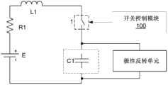
为了对处于低温环境中的电池E进行加热,本发明提供了一种电池E的加热电路,如图1所示,该加热电路包括开关装置1、开关控制模块100、阻尼元件R1、储能电路以及能量叠加单元,所述储能电路用于与所述电池连接以构成回路,所述储能电路包括电流存储元件L1和电荷存储元件C1,所述阻尼元件R1、开关装置1、电流存储元件L1和电荷存储元件C1串联,所述开关控制模块100与开关装置1连接,用于控制开关装置1导通和关断,以控制能量在所述电池与所述储能电路之间的流动,所述能量叠加单元与所述储能电路连接,用于在开关装置1导通再关断后,将储能电路中的能量与电池中的能量进行叠加;所述开关控制模块100用于在开关装置1导通后流经开关装置1的电流的第一正半周期之后控制开关装置1关断,且该开关装置1关断时施加到该开关装置1上的电压小于该开关装置1的额定电压。In order to heat the battery E in a low temperature environment, the present invention provides a heating circuit for the battery E, as shown in Figure 1, the heating circuit includes a
根据本发明的技术方案,当达到加热条件时,开关控制模块100控制开关装置1导通,电池E与储能电路串联构成回路,电池E可以通过回路放电,即对电荷存储元件C1进行充电,当回路中的电流经过电流峰值后正向为零时,电荷存储元件C1开始通过回路放电,即是对电池E充电;在电池E的充放电过程中,回路中的电流正向、反向均能流过阻尼元件R1,通过阻尼元件R1的发热可以达到给电池E加热的目的,当达到停止加热条件时,开关控制模块100可以控制开关装置1关断,加热电路停止工作。According to the technical solution of the present invention, when the heating condition is reached, the
为了实现能量在电池E与储能电路之间的往复流动,根据本发明的一种实施方式,所述开关装置1为双向开关K3,如图2所示。由开关控制模块100控制双向开关K3的导通与关断,当需要对电池E加热时,导通双向开关K3即可,如暂停加热或者不需要加热时关断双向开关K3即可。In order to realize the reciprocating flow of energy between the battery E and the energy storage circuit, according to an embodiment of the present invention, the
单独使用一个双向开关K3实现开关装置1,电路简单,占用系统面积小,容易实现,但是为了实现对反向电流的关断,本发明还提供了如下开关装置1的优选实施方式。Using a single bidirectional switch K3 to implement the
优选地,所述开关装置1包括用于实现能量从电池E流向储能电路的第一单向支路和用于实现能量从储能电路流向电池E的第二单向支路,所述开关控制模块100与所述第一单向支路和第二单向支路分别连接,用于通过控制所连接的支路的导通和关断来控制开关装置1导通和关断。Preferably, the
当电池需要加热时,导通第一单向支路和第二单向支路两者,如暂停加热可以选择关断第一单向支路和第二单向支路中的一者或两者,当不需要加热时,可以关断第一单向支路和第二单向支路两者。优选地,第一单向支路和第二单向支路两者都能够受开关控制模块100的控制,这样,可以灵活实现能量正向流动和反向流动。When the battery needs to be heated, turn on both the first one-way branch and the second one-way branch, such as pausing heating, you can choose to turn off one or both of the first one-way branch and the second one-way branch Or, when heating is not required, both the first one-way branch and the second one-way branch can be turned off. Preferably, both the first unidirectional branch and the second unidirectional branch can be controlled by the
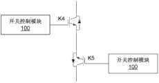
作为开关装置1的另一种实施方式,如图3所示,所述开关装置1可以包括双向开关K4和双向开关K5,所述双向开关K4和双向开关K5彼此反向串联以构成所述第一单向支路和第二单向支路,所述开关控制模块100与所述双向开关K4和双向开关K5分别连接,用于通过控制双向开关K4和双向开关K5的导通和关断来控制第一单向支路和第二单向支路的导通和关断。As another implementation of the
当需要对电池E加热时,导通双向开关K4和K5即可,如暂停加热可以选择关断双向开关K4和双向开关K5中的一者或者两者,在不需要加热时关断双向开关K4和双向开关K5即可。这种开关装置1的实现方式能够分别控制第一单向支路和第二单向支路的导通和关断,灵活实现电路的正向和反向能量流动。When the battery E needs to be heated, it is enough to turn on the bidirectional switches K4 and K5. If the heating is suspended, one or both of the bidirectional switch K4 and the bidirectional switch K5 can be selected to be turned off. When heating is not required, the bidirectional switch K4 can be turned off. and bidirectional switch K5. The implementation of the
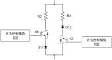
作为开关装置1的另一种实施方式,如图4所示,所述开关装置1包括开关K6、单向半导体元件D11、开关K7以及单向半导体元件D12,开关K6和单向半导体元件D11彼此串联以构成所述第一单向支路,开关K7与单向半导体元件D12彼此串联以构成所述第二单向支路,所述开关控制模块100与开关K6和开关K7分别连接,用于通过控制开关K6和开关K7的导通和关断来控制第一单向支路和第二单向支路的导通和关断。在图4示出的开关装置1中,由于两个单向支路上均存在开关(即开关K6和开关K7),同时具备能量正向和反向流动时的关断功能。As another embodiment of the
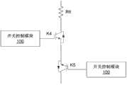
优选地,所述开关装置1还可以包括与所述第一单向支路和/或第二单向支路串联的电阻,用于减小电池E加热回路的电流,避免回路中电流过大对电池E造成损害。例如,可以在图3中示出的开关装置1中添加与双向开关K4和双向开关K5串联的电阻R6,得到开关装置1的另一种实现方式,如图5所示。图6中也示出了开关装置1的一种实施方式,其是在图4中示出的开关装置1中的两个单向支路上分别串联电阻R2、电阻R3得到的。Preferably, the
由于回路中电流存储元件L1的存在,在回路中存在电流时关断开关装置1,电流突变为零可能会使得回路中的电流存储元件L1产生较大的感应电压,可能损坏回路中的其他电路元件(如开关装置1)。为了提高加热电路的安全性,根据本发明的技术方案,所述开关控制模块100可对开关装置1关断的时机进行选择,使得开关装置1关断时施加到该开关装置1上的电压小于该开关装置1的额定电压。可通过根据开关装置1的额定电压来确定所述开关装置1关断的时机,可以避免因回路中的电流存储元件L1产生的感应电压过大而损坏开关装置1,使得加热电路的安全性更高,对整个电路影响较小。Due to the existence of the current storage element L1 in the loop, the
其中,所述关断时机例如可为流经开关装置1的电流的负半周期峰值后过零前30度到下一正半周期峰值前过零后30度的时间区间,开关装置1的关断时刻可以是该时间区间内的任意时刻。当然本发明并不限于此,具体的时间区间应根据开关装置1的额定电压来确定,例如对于不同的额定电压而言,亦可为流经开关装置1的电流的负半周期峰值后过零前60度到下一正半周期峰值前过零后60度的时间区间。Wherein, the turn-off timing may be, for example, a time interval from 30 degrees before the zero-crossing after the negative half-cycle peak value of the current flowing through the
由于在对电池E循环充放电过程中,当对电池E反向充电时,能量不会全部充回到电池E中,由此会导致电池E的下一次正向放电中能量的减少,降低了加热电路的加热效率。因此,优选地,所述开关控制模块100用于在开关装置1导通后流经开关装置1的电流经负半周期峰值后为零时控制开关装置1关断,以提高加热电路的加热效率,且此时控制开关装置1关断,可使得电流存储元件L1感应产生的电压最小,从而使得施加到该开关装置1上的电压最小,藉此避免高电压损坏开关装置1。Because in the process of charging and discharging the battery E, when the battery E is reversely charged, the energy will not be fully charged back into the battery E, which will lead to a decrease in the energy of the next forward discharge of the battery E, reducing the Heating efficiency of the heating circuit. Therefore, preferably, the
优选地,如图7所示,所述加热电路还包括续流电路20,该续流电路20用于在所述开关装置1导通再关断后,与所述电池E和电流存储元件L构成串联回路,以保持电池E内电流的流动。由此,在开关装置1关断后,通过控制续流电路20工作,可以保持电流的继续流动,从而能够保护电路中的其他电路元件(如开关装置1),保证加热电路的安全性。该续流电路的使用使得上述开关装置1的关断时机更为宽泛。Preferably, as shown in FIG. 7, the heating circuit further includes a
根据本发明的一种实施方式,所述开关控制模块100用于在开关装置1导通后流经开关装置1的电流的负半周期峰值后过零前控制开关装置1关断,如图8所示,所述续流电路20可以包括相互串联的开关K20和单向半导体元件D20,所述开关控制模块100与开关K20连接,用于在开关装置1导通再关断后,控制开关K20导通,而在流向电池E的电流为电流预定值(例如为零)后,控制开关K20关断。所述续流电路20可以并联在所述电池E两端,也可以一端连接到如图4所示的开关装置1的第二单向支路上的开关K7和单向半导体元件D12之间,另一端连接到所述电池E。According to an embodiment of the present invention, the
所述电流预定值为不会导致开关装置1关断时施加到开关装置1上的电压大于或等于开关装置1的额定电压的电流值,该电流值可以根据开关装置1的额定电压的大小进行设定。The predetermined current value will not cause the voltage applied to the
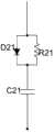
根据本发明的另一种实施方式,所述开关控制模块100用于在开关装置1导通后流经开关装置1的电流的正半周期峰值前过零后控制开关装置1关断,如图9所示,所述续流电路20可以包括单向半导体元件D21、阻尼元件R21和电荷存储元件C21,所述单向半导体元件D21与阻尼元件R21并联之后再与所述电荷存储元件C21串联,在开关装置1导通再关断后,电流存储元件L1可以通过单向半导体元件D21和电荷存储元件C21续流,阻尼元件R21用于释放存储在电荷存储元件C21上的能量。所述续流电路20可以并联在所述电池E两端,也可以一端连接到如图4所示的开关装置1的第一单向支路上的开关K6和单向半导体元件D11之间,另一端连接到所述电池E。According to another embodiment of the present invention, the
所述能量叠加单元与所述储能电路连接,用于在开关装置1导通再关断后,将储能电路中的能量与电池E中的能量进行叠加,以使得在开关装置1再次导通时,提高加热回路中的放电电流,从而提高加热电路的工作效率。The energy superposition unit is connected to the energy storage circuit, and is used to superimpose the energy in the energy storage circuit and the energy in the battery E after the
根据本发明的一种实施方式,如图10所示,所述能量叠加单元包括极性反转单元102,该极性反转单元102与所述储能电路连接,用于在开关装置1导通再关断后,对电荷存储元件C1的电压极性进行反转,由于极性反转后的电荷存储元件C1的电压能够与电池E的电压串联相加,当开关装置1再次导通时,能够提高加热回路中的放电电流。According to an embodiment of the present invention, as shown in FIG. 10 , the energy superposition unit includes a polarity inversion unit 102 connected to the energy storage circuit for conducting After turning on and off again, the voltage polarity of the charge storage element C1 is reversed. Since the voltage of the charge storage element C1 after polarity reversal can be added in series with the voltage of the battery E, when the
作为极性反转单元102的一种实施方式,如图11所示,所述极性反转单元102包括单刀双掷开关J1和单刀双掷开关J2,所述单刀双掷开关J1和单刀双掷开关J2分别位于所述电荷存储元件C1两端,所述单刀双掷开关J1的入线连接在所述储能电路中,所述单刀双掷开关J1的第一出线连接所述电荷存储元件C1的第一极板,所述单刀双掷开关J1的第二出线连接所述电荷存储元件C1的第二极板,所述单刀双掷开关J2的入线连接在所述储能电路中,所述单刀双掷开关J2的第一出线连接所述电荷存储元件C1的第二极板,所述单刀双掷开关J2的第二出线连接在所述电荷存储元件C1的第一极板,所述开关控制模块100还与所述单刀双掷开关J1和单刀双掷开关J2分别连接,用于通过改变所述单刀双掷开关J1和单刀双掷开关J2各自的入线和出线的连接关系来对所述电荷存储元件C1的电压极性进行反转。As an implementation of the polarity inversion unit 102, as shown in FIG. 11, the polarity inversion unit 102 includes a single-pole double-throw switch J1 and a single-pole double-throw switch J2 The throw switch J2 is respectively located at both ends of the charge storage element C1, the input line of the SPDT switch J1 is connected to the energy storage circuit, and the first output line of the SPDT switch J1 is connected to the charge storage element the first pole plate of C1, the second outgoing line of the SPDT switch J1 is connected to the second pole plate of the charge storage element C1, the incoming line of the SPDT switch J2 is connected in the energy storage circuit, The first outgoing line of the SPDT switch J2 is connected to the second plate of the charge storage element C1, and the second outgoing line of the SPDT switch J2 is connected to the first plate of the charge storage element C1, so The
根据该实施方式,可以预先对单刀双掷开关J1和单刀双掷开关J2各自的入线和出线的连接关系进行设置,使得当开关装置K1导通时,所述单刀双掷开关J1的入线与其第一出线连接,而所述单刀双掷开关J2的入线与其第一出线连接,当开关装置K1关断时,通过开关控制模块100控制单刀双掷开关J1的入线切换到与其第二出线连接,而所述单刀双掷开关J2的入线切换到与其第二出线连接,由此电荷存储元件C1实现电压极性反转的目的。According to this embodiment, the connection relationship between the incoming and outgoing lines of the SPDT switch J1 and the SPDT switch J2 can be set in advance, so that when the switch device K1 is turned on, the incoming line of the SPDT switch J1 It is connected to its first outgoing line, and the incoming line of the single pole double throw switch J2 is connected to its first outgoing line. When the switch device K1 is turned off, the incoming line of the single pole double throw switch J1 is controlled by the
作为极性反转单元102的另一种实施方式,如图12所示,所述极性反转单元102包括单向半导体元件D3、电流存储元件L2以及开关K9,所述电荷存储元件C1、电流存储元件L2和开关K9顺次串联形成回路,所述单向半导体元件D3和串联在所述电荷存储元件C1与电流存储元件L2或所述电流存储元件L2与开关K9之间,所述开关控制模块100还与所述开关K9连接,用于通过控制开关K9导通来对所述电荷存储元件C1的电压极性进行反转。As another implementation of the polarity inversion unit 102, as shown in FIG. 12, the polarity inversion unit 102 includes a unidirectional semiconductor element D3, a current storage element L2, and a switch K9. The current storage element L2 and the switch K9 are connected in series to form a loop, and the unidirectional semiconductor element D3 is connected in series between the charge storage element C1 and the current storage element L2 or between the current storage element L2 and the switch K9, and the switch The
根据上述实施方式,当开关装置1关断时,可以通过开关控制模块100控制开关K9导通,由此,电荷存储元件C1与单向半导体元件D3、电流存储元件L2以及开关K9形成LC振荡回路,电荷存储元件C1通过电流存储元件L2放电,振荡回路上的电流流经正半周期后,流经电流存储元件L2的电流为零时达到电荷存储元件C1电压极性反转的目的。According to the above embodiment, when the
作为极性反转单元102的又一种实施方式,如图13所示,所述极性反转单元102包括第一DC-DC模块2和电荷存储元件C2,该第一DC-DC模块2与所述电荷存储元件C1和电荷存储元件C2分别连接,所述开关控制模块100还与所述第一DC-DC模块2连接,用于通过控制第一DC-DC模块2工作来将所述电荷存储元件C1中的能量转移至所述电荷存储元件C2,再将所述电荷存储元件C2中的能量反向转移回所述电荷存储元件C1,以实现对所述电荷存储元件C1的电压极性的反转。As yet another embodiment of the polarity inversion unit 102, as shown in FIG. 13, the polarity inversion unit 102 includes a first DC-
所述第一DC-DC模块2是本领域中常用的用于实现电压极性反转的直流变直流转换电路,本发明不对第一DC-DC模块2的具体电路结构作任何限制,只要能够实现对电荷存储元件C1的电压极性反转即可,本领域技术人员可以根据实际操作的需要对其电路中的元件进行增加、替换或删减。The first DC-
图14为本发明提供的第一DC-DC模块2的一种实施方式,如图14所示,所述第一DC-DC模块2包括:双向开关Q1、双向开关Q2、双向开关Q3、双向开关Q4、第一变压器T1、单向半导体元件D4、单向半导体元件D5、电流存储元件L3、双向开关Q5、双向开关Q6、第二变压器T2、单向半导体元件D6、单向半导体元件D7、以及单向半导体元件D8。Fig. 14 is an embodiment of the first DC-
在该实施方式中,所述双向开关Q1、双向开关Q2、双向开关Q3和双向开关Q4为MOSFET,所述双向开关Q5和双向开关Q6为IGBT。In this embodiment, the bidirectional switch Q1 , the bidirectional switch Q2 , the bidirectional switch Q3 and the bidirectional switch Q4 are MOSFETs, and the bidirectional switch Q5 and the bidirectional switch Q6 are IGBTs.
所述第一变压器T1的1脚、4脚、5脚为同名端,第二变压器T2的2脚与3脚为同名端。
其中,单向半导体元件D7的阳极与电荷存储元件C1的a端连接,单向半导体元件D7的阴极与双向开关Q1和双向开关Q2的漏极连接,双向开关Q1的源极与双向开关Q3的漏极连接,双向开关Q2的源极与双向开关Q4的漏极连接,双向开关Q3、双向开关Q4的源极与电荷存储元件C1的b端连接,由此构成全桥电路,此时电荷存储元件C1的电压极性为a端为正,b端为负。Wherein, the anode of the unidirectional semiconductor element D7 is connected to the terminal a of the charge storage element C1, the cathode of the unidirectional semiconductor element D7 is connected to the drains of the bidirectional switch Q1 and the bidirectional switch Q2, and the source of the bidirectional switch Q1 is connected to the bidirectional switch Q3. The drain is connected, the source of the bidirectional switch Q2 is connected to the drain of the bidirectional switch Q4, the sources of the bidirectional switch Q3 and the bidirectional switch Q4 are connected to the b terminal of the charge storage element C1, thereby forming a full bridge circuit, and the charge is stored at this time The voltage polarity of component C1 is positive at terminal a and negative at terminal b.
在该全桥电路中,双向开关Q1、双向开关Q2为上桥臂,双向开关Q3、双向开关Q4为下桥臂,该全桥电路通过第一变压器T1与所述电荷存储元件C2相连;第一变压器T1的1脚与第一节点N1连接、2脚与第二节点N2连接,3脚和5脚分别连接至单向半导体元件D4和单向半导体元件D5的阳极;单向半导体元件D4和单向半导体元件D5的阴极与电流存储元件L3的一端连接,电流存储元件L3的另一端与电荷存储元件C2的d端连接;变压器T1的4脚与电荷存储元件C2的c端连接,单向半导体元件D8的阳极与电荷存储元件C2的d端连接,单向半导体元件D8的阴极与电荷存储元件C1的b端连接,此时电荷存储元件C2的电压极性为c端为负,d端为正。In the full bridge circuit, the bidirectional switch Q1 and the bidirectional switch Q2 are the upper bridge arms, the bidirectional switch Q3 and the bidirectional switch Q4 are the lower bridge arms, and the full bridge circuit is connected to the charge storage element C2 through the first transformer T1; the
其中,电荷存储元件C2的c端连接双向开关Q5的发射极,双向开关Q5的集电极与变压器T2的2脚连接,变压器T2的1脚与电荷存储元件C1的a端连接,变压器T2的4脚与电荷存储元件C1的a端连接,变压器T2的3脚连接单向半导体元件D6的阳极,单向半导体元件D6的阴极与双向开关Q6的集电极连接,双向开关Q6的发射极与电荷存储元件C2的b端连接。Wherein, the c terminal of the charge storage element C2 is connected to the emitter of the bidirectional switch Q5, the collector of the bidirectional switch Q5 is connected to the 2 pin of the transformer T2, the 1 pin of the transformer T2 is connected to the a terminal of the charge storage element C1, and the 4 pin of the transformer T2 The pin is connected to the a terminal of the charge storage element C1, the 3 pin of the transformer T2 is connected to the anode of the unidirectional semiconductor element D6, the cathode of the unidirectional semiconductor element D6 is connected to the collector of the bidirectional switch Q6, and the emitter of the bidirectional switch Q6 is connected to the charge storage Terminal b of element C2 is connected.
其中,双向开关Q1、双向开关Q2、双向开关Q3、双向开关Q4、双向开关Q5和双向开关Q6分别通过所述开关控制模块100的控制来实现导通和关断。Wherein, the bidirectional switch Q1 , bidirectional switch Q2 , bidirectional switch Q3 , bidirectional switch Q4 , bidirectional switch Q5 and bidirectional switch Q6 are respectively turned on and off under the control of the
下面对所述第一DC-DC模块2的工作过程进行描述:The working process of the first DC-
1、在开关装置1关断后,所述开关控制模块100控制双向开关Q5、双向开关Q6关断,控制双向开关Q1和双向开关Q4同时导通以构成A相,控制双向开关Q2、双向开关Q3同时导通以构成B相,通过控制所述A相、B相交替导通以构成全桥电路进行工作;1. After the
2、当所述全桥电路工作时,电荷存储元件C1上的能量通过第一变压器T1、单向半导体元件D4、单向半导体元件D5、以及电流存储元件L3转移到电荷存储元件C2上,此时电荷存储元件C2的电压极性为c端为负,d端为正。2. When the full bridge circuit is working, the energy on the charge storage element C1 is transferred to the charge storage element C2 through the first transformer T1, the unidirectional semiconductor element D4, the unidirectional semiconductor element D5, and the current storage element L3. At this time, the voltage polarity of the charge storage element C2 is negative at the c terminal and positive at the d terminal.
3、所述开关控制模块100控制双向开关Q5导通,电荷存储元件C1通过第二变压器T2和单向半导体元件D8与电荷存储元件C2构成通路,由此,电荷存储元件C2上的能量向电荷存储元件C1反向转移,其中,部分能量将储存在第二变压器T2上;此时,所述开关控制模块100控制双向开关Q5关断、双向开关Q6闭合,通过第二变压器T2和单向半导体元件D6将储存在第二变压器T2上的能量转移至电荷存储元件C1,此时电荷存储元件C1的电压极性反转为a端为负,b端为正,由此达到了将电荷存储元件C1的电压极性反向的目的。3. The
作为本发明的一种实施方式,可以通过将电荷存储元件C1中的能量直接与电池E中的能量进行叠加来提高加热电路的工作效率,也可以将电荷存储元件C1中的一部分能量消耗掉之后,再将电荷存储元件C1中的剩余能量进行叠加。As an embodiment of the present invention, the working efficiency of the heating circuit can be improved by directly superimposing the energy in the charge storage element C1 with the energy in the battery E, or after a part of the energy in the charge storage element C1 is consumed , and then superpose the remaining energy in the charge storage element C1.
因此,如图15所示,所述加热电路还包括与所述电荷存储元件C1连接的能量消耗单元,该能量消耗单元用于在开关装置1导通再关断后、所述能量叠加单元进行能量叠加之前对电荷存储元件C1中的能量进行消耗。Therefore, as shown in FIG. 15 , the heating circuit further includes an energy consumption unit connected to the charge storage element C1, and the energy consumption unit is used for the energy superposition unit to perform The energy in the charge storage element C1 is consumed before energy superposition.
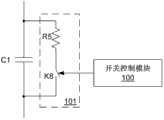
根据一种实施方式,如图16所示,所述能量消耗单元包括电压控制单元101,该电压控制单元101用于在开关装置1导通再关断后、所述能量叠加单元进行能量叠加之前将电荷存储元件C1两端的电压值转换成电压设定值。该电压设定值可以根据实际操作的需要进行设定。According to one embodiment, as shown in FIG. 16 , the energy consumption unit includes a
如图16所示,所述电压控制单元101包括阻尼元件R5和开关K8,所述阻尼元件R5和开关K8彼此串联之后并联在所述电荷存储元件C1的两端,所述开关控制模块100还与开关K8连接,所述开关控制模块100还用于在控制开关装置1导通再关断后控制开关K8导通。由此,电荷存储元件C1中的能量可以通过阻尼元件R5进行消耗。As shown in FIG. 16, the
所述开关控制模块100可以为一个单独的控制器,通过对其内部程序的设置,可以实现对不同的外接开关的通断控制,所述开关控制模块100也可以为多个控制器,例如针对每一个外接开关设置对应的开关控制模块100,所述多个开关控制模块100也可以集成为一体,本发明不对开关控制模块100的实现形式做出任何限定。The
下面结合图17-图22对电池E的加热电路的实施方式的工作方式进行简单介绍。需要注意的是,虽然本发明的特征和元素参考图17-图22以特定的结合进行了描述,但每个特征或元素可以在没有其它特征和元素的情况下单独使用,或在与或不与其它特征和元素结合的各种情况下使用。本发明提供的电池E的加热电路的实施方式并不限于图17-图22所示的实现方式。另外,所示的波形图中的各个时间段之间的间隔时间可以根据实际操作的需要进行调节。The working mode of the embodiment of the heating circuit of the battery E will be briefly introduced below with reference to FIGS. 17-22 . It should be noted that although features and elements of the present invention are described in particular combinations with reference to FIGS. Used in various contexts in combination with other features and elements. The implementation of the heating circuit of the battery E provided by the present invention is not limited to the implementations shown in FIGS. 17-22 . In addition, the time intervals between the various time periods in the shown waveform diagram can be adjusted according to actual operation needs.
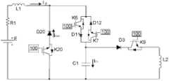
在如图17所示的电池E的加热电路中,开关K6和单向半导体元件D11串联构成开关装置1的第一单向支路,单向半导体元件D12和开关K7串联构成开关装置1的第二单向支路,该开关装置1与阻尼元件R1、电荷存储元件C1以及电流存储元件L1串联,单向半导体元件D3、电流存储元件L2和开关K9构成极性反转单元102,单向半导体元件D20和开关K20构成续流电路20,开关控制模块100可以控制开关K6、开关K7、开关K9和开关K20的导通和关断。图18为与图17的加热电路对应的波形时序图,其中,VC1指的是电荷存储元件C1的电压值,I主指的是流经开关装置1的电流的电流值,IL2指的是极性反转回路的电流值,IC1指的是电荷存储元件C1上的电流值,ID20指的是单向半导体元件D20上的电流值。图17所示的加热电路的工作过程如下:In the heating circuit of the battery E shown in Figure 17, the switch K6 and the unidirectional semiconductor element D11 are connected in series to form the first unidirectional branch of the
a)开关控制模块100控制开关K6导通,电池E通过与开关K6、单向半导体元件D11、电荷存储元件C1组成的回路进行正向放电(如图18中的t1时间段所示);a) The
b)开关控制模块100控制开关K6在电流经过第一个正半周期峰值后为零时关断;b) the
c)开关控制模块100控制开关K7导通,电池E通过与电荷存储元件C1、开关K7、半导体器件D12组成的回路进行反向充电;开关控制模块100控制开关K7在电流经过第一个负半周期峰值后过零前24度时关断(如图18中的t2时间段所示);c) The
d)开关控制模块100在控制开关K7关断的同时,控制开关K20导通,电流存储元件L1通过开关K20、单向半导体元件D20续流,开关控制模块100在流向电池E的电流为零时控制开关K20关断(如图18中的t3时间段所示);d) The
e)开关控制模块100控制开关K9导通,电荷存储元件C1通过单向半导体元件D3、电流存储元件L2和开关K9组成的回路放电,并达到电压极性反转的目的,之后,开关控制模块100控制开关K9关断(如图18中的t4时间段所示);e) The
f)重复步骤a)至e),电池E不断通过充放电实现加热,直至电池达到停止加热条件为止。f) Steps a) to e) are repeated, and the battery E is continuously heated by charging and discharging until the battery reaches the condition of stopping heating.
在如图19所示的电池E的加热电路中,开关K6和单向半导体元件D11串联构成开关装置1的第一单向支路,单向半导体元件D12和开关K7串联构成开关装置1的第二单向支路,该开关装置1与阻尼元件R1、电荷存储元件C1以及电流存储元件L1串联,单向半导体元件D3、电流存储元件L2和开关K9构成极性反转单元102,单向半导体元件D21、阻尼元件R21和电荷存储元件C21构成续流电路20,开关控制模块100可以控制开关K6、开关K7和开关K9的导通和关断。图20为与图19的加热电路对应的波形时序图,其中,VC1指的是电荷存储元件C1的电压值,I主指的是流经开关装置1的电流的电流值,IL2指的是极性反转回路的电流值,IC1指的是电荷存储元件C1上的电流值,IC21指的是电荷存储元件C21上的电流值。图19所示的加热电路的工作过程如下:In the heating circuit of the battery E shown in Figure 19, the switch K6 and the unidirectional semiconductor element D11 are connected in series to form the first unidirectional branch of the
a)开关控制模块100控制开关K6、K7导通,电池E通过与开关K6、单向半导体元件D11、电荷存储元件C1组成的回路进行正向放电(如图20中的t1时间段所示)以及与开关K7、单向半导体元件D12、电荷存储元件C1组成的回路进行反向充电(如图20中的t2时间段所示);a) The
b)开关控制模块100控制开关K6、K7在电流的第二个正半周期峰值前过零后25度时关断(如图20中的t3时间段所示),电流存储元件L1通过单向半导体元件D21和电荷存储元件C21续流(如图20中的t4时间段所示);b) The
c)开关控制模块100控制开关K9导通,电荷存储元件C1通过单向半导体元件D3、电流存储元件L2和开关K9组成的回路放电,并达到电压极性反转的目的,之后,开关控制模块100控制开关K9关断(如图20中的t5时间段所示);c) The
d)重复步骤a)至c),电池E不断通过充放电实现加热,直至电池达到停止加热条件为止。d) Steps a) to c) are repeated, and the battery E is continuously heated through charging and discharging until the battery reaches the condition of stopping heating.
需要说明的是,图19中的续流电路20于t1和t2时间段亦有电流流过,出于清楚绘示续流电路20于本加热电路内的作用的目的,图20中仅示出了续流电路20于体现其具体作用的时间段的电流情况,而未示出续流电路20于t1和t2时间段的电流情况,以避免混淆本发明。It should be noted that the
在如图21所示的电池E的加热电路中,使用一个双向开关K3构成开关装置1,储能电路包括电流存储元件L1和电荷存储元件C1,阻尼元件R1和开关装置1与所述储能电路串联,单向半导体元件D3、电流存储元件L2和开关K9构成极性反转单元102,开关控制模块100可以控制开关K9和双向开关K3的导通和关断。图22为与图21的加热电路对应的波形时序图,其中,VC1指的是电荷存储元件C1的电压值,I主指的是流经双向开关K3的电流的电流值,IL2指的是极性反转回路的电流值。图21所示的加热电路的工作过程如下:In the heating circuit of the battery E shown in Figure 21, a bidirectional switch K3 is used to form the
a)开关控制模块100控制双向开关K3导通,储能电路开始工作,如图20所示的t1时间段,电池E通过双向开关K3、电荷存储元件C1组成的回路进行正向放电和反向充电(如图22中的t1时间段所示);a) The
b)开关控制模块100在流经双向开关K3的电流的经过负半周期峰值后为零时(即反向电流为零时)控制双向开关K3关断;b) The
c)开关控制模块100控制开关K9导通,极性反转单元102工作,电荷存储元件C1通过单向半导体元件D3、电流存储元件L2和开关K9组成的回路放电,达到电压极性反转的目的,之后,开关控制模块100控制开关K9关断(如图22中的t2时间段所示);c) The
d)重复步骤a)至c),电池E不断通过充放电实现加热,直至电池E达到停止加热条件为止。d) Steps a) to c) are repeated, and the battery E is continuously heated through charging and discharging until the battery E reaches the heating stop condition.
本发明提供的加热电路能够提高电池的充放电性能,并且在该加热电路中,储能电路与电池串联,当给电池加热时,由于串联的电荷存储元件的存在,能够避免开关装置失效短路引起的安全性问题,能够有效地保护电池。The heating circuit provided by the present invention can improve the charging and discharging performance of the battery, and in the heating circuit, the energy storage circuit is connected in series with the battery, and when the battery is heated, due to the existence of the charge storage element connected in series, it is possible to avoid failure of the switching device caused by a short circuit. Safety issues, can effectively protect the battery.
另外,在本发明的加热电路中,由于开关装置的关断时机是根据开关装置的额定电压而选取的,可以避免因回路中的电流存储元件产生的感应电压过大而损坏开关装置,使得加热电路的安全性更高,对整个电路影响较小。In addition, in the heating circuit of the present invention, since the turn-off timing of the switch device is selected according to the rated voltage of the switch device, it is possible to avoid damage to the switch device due to the excessive induced voltage generated by the current storage element in the circuit, causing heating The safety of the circuit is higher, and the influence on the whole circuit is small.
同时,本发明的加热电路中还提供了能量叠加单元,当开关装置关断后,该能量叠加单元能够将储能电路中的能量与电池中的能量进行叠加,当下一次控制开关装置导通时,提高加热回路中的放电电流,由此提高加热电路的工作效率。At the same time, the heating circuit of the present invention also provides an energy superimposing unit. When the switch device is turned off, the energy superimposing unit can superimpose the energy in the energy storage circuit and the energy in the battery. When the control switch device is turned on next time , increase the discharge current in the heating circuit, thereby increasing the working efficiency of the heating circuit.
以上结合附图详细描述了本发明的优选实施方式,但是,本发明并不限于上述实施方式中的具体细节,在本发明的技术构思范围内,可以对本发明的技术方案进行多种简单变型,这些简单变型均属于本发明的保护范围。The preferred embodiment of the present invention has been described in detail above in conjunction with the accompanying drawings, but the present invention is not limited to the specific details of the above embodiment, within the scope of the technical concept of the present invention, various simple modifications can be made to the technical solution of the present invention, These simple modifications all belong to the protection scope of the present invention.
另外需要说明的是,在上述具体实施方式中所描述的各个具体技术特征,在不矛盾的情况下,可以通过任何合适的方式进行组合,为了避免不必要的重复,本发明对各种可能的组合方式不再另行说明。此外,本发明的各种不同的实施方式之间也可以进行任意组合,只要其不违背本发明的思想,其同样应当视为本发明所公开的内容。In addition, it should be noted that the various specific technical features described in the above specific embodiments can be combined in any suitable way if there is no contradiction. The combination method will not be described separately. In addition, various combinations of different embodiments of the present invention can also be combined arbitrarily, as long as they do not violate the idea of the present invention, they should also be regarded as the disclosed content of the present invention.
Claims (19)
Priority Applications (3)
| Application Number | Priority Date | Filing Date | Title |
|---|---|---|---|
| CN2011101372648ACN102306849B (en) | 2010-07-30 | 2011-05-23 | Heating circuit for battery |
| US13/187,279US8975872B2 (en) | 2010-07-30 | 2011-07-20 | Battery heating circuits and methods with resonance components in series using voltage inversion based on predetermined conditions |
| US13/748,525US8994332B2 (en) | 2010-07-30 | 2013-01-23 | Battery heating circuits and methods using voltage inversion based on predetermined conditions |
Applications Claiming Priority (5)
| Application Number | Priority Date | Filing Date | Title |
|---|---|---|---|
| CN201010245288 | 2010-07-30 | ||
| CN201010245288.0 | 2010-07-30 | ||
| CN201010274785.3 | 2010-08-30 | ||
| CN201010274785 | 2010-08-30 | ||
| CN2011101372648ACN102306849B (en) | 2010-07-30 | 2011-05-23 | Heating circuit for battery |
Publications (2)
| Publication Number | Publication Date |
|---|---|
| CN102306849Atrue CN102306849A (en) | 2012-01-04 |
| CN102306849B CN102306849B (en) | 2013-01-02 |
Family
ID=44033178
Family Applications (34)
| Application Number | Title | Priority Date | Filing Date |
|---|---|---|---|
| CN2010206777270UExpired - LifetimeCN201936967U (en) | 2010-07-30 | 2010-12-23 | Heating circuit of battery |
| CN2010106060826AActiveCN102088117B (en) | 2010-07-30 | 2010-12-23 | Battery heating circuit |
| CN2010206777124UExpired - LifetimeCN201966300U (en) | 2010-07-30 | 2010-12-23 | Heating circuit of battery |
| CN2010106047145AActiveCN102074759B (en) | 2010-07-30 | 2010-12-23 | Heating circuit of battery |
| CN2010206793521UExpired - LifetimeCN202009060U (en) | 2010-07-30 | 2010-12-23 | Heating circuit of battery |
| CN2010106036583AActiveCN102082306B (en) | 2010-07-30 | 2010-12-23 | Heating circuit of battery |
| CN201010605772XAActiveCN102088116B (en) | 2010-07-30 | 2010-12-23 | Heating circuit of battery |
| CN2010206777444UExpired - Fee RelatedCN202042565U (en) | 2010-07-30 | 2010-12-23 | battery heating circuit |
| CN2010106046778AActiveCN102074758B (en) | 2010-07-30 | 2010-12-23 | Heating circuit of battery |
| CN2010106047770AActiveCN102074762B (en) | 2010-07-30 | 2010-12-23 | Heating circuit of battery |
| CN2010106037177AActiveCN102074755B (en) | 2010-07-30 | 2010-12-23 | Heating circuit of battery |
| CN2010206793517UExpired - LifetimeCN202042568U (en) | 2010-07-30 | 2010-12-23 | battery heating circuit |
| CN2010206776278UExpired - LifetimeCN201936969U (en) | 2010-07-30 | 2010-12-23 | Battery heating circuit |
| CN201020678144XUExpired - Fee RelatedCN202009058U (en) | 2010-07-30 | 2010-12-23 | Heating circuit for batteries |
| CN2010206781454UExpired - LifetimeCN202042566U (en) | 2010-07-30 | 2010-12-23 | battery heating circuit |
| CN2010206777942UExpired - LifetimeCN202042572U (en) | 2010-07-30 | 2010-12-23 | battery heating circuit |
| CN201020677616XUExpired - LifetimeCN201936966U (en) | 2010-07-30 | 2010-12-23 | Battery heating circuit |
| CN2010106034713AActiveCN102074753B (en) | 2010-07-30 | 2010-12-23 | Heating circuit of battery |
| CN2010206793023UExpired - LifetimeCN202042567U (en) | 2010-07-30 | 2010-12-23 | battery heating circuit |
| CN2010106047446AActiveCN102074761B (en) | 2010-07-30 | 2010-12-23 | Heating circuit of battery |
| CN2010106037196AActiveCN102074756B (en) | 2010-07-30 | 2010-12-23 | Heating circuit of battery |
| CN2010106047291AActiveCN102074760B (en) | 2010-07-30 | 2010-12-23 | Heating circuit of battery |
| CN2011100808537AActiveCN102170030B (en) | 2010-07-30 | 2011-03-31 | Heating circuit for battery |
| CN2011200926539UExpired - LifetimeCN202076380U (en) | 2010-07-30 | 2011-03-31 | Heating circuit of battery |
| CN2011200926219UExpired - LifetimeCN202076379U (en) | 2010-07-30 | 2011-03-31 | Heating circuit of battery |
| CN2011200935557UExpired - LifetimeCN202076381U (en) | 2010-07-30 | 2011-03-31 | Heating circuit of battery |
| CN2011100812763AActiveCN102255108B (en) | 2010-07-30 | 2011-03-31 | Heating circuit for battery |
| CN2011100812195AActiveCN102170031B (en) | 2010-07-30 | 2011-03-31 | Heating circuit for battery |
| CN2011201641194UExpired - LifetimeCN202145485U (en) | 2010-07-30 | 2011-05-20 | Heating circuit of batteries |
| CN2011101323622AActiveCN102255110B (en) | 2010-07-30 | 2011-05-20 | battery heating circuit |
| CN201110134005XAActiveCN102255111B (en) | 2010-07-30 | 2011-05-23 | battery heating circuit |
| CN201120165898XUExpired - LifetimeCN202103139U (en) | 2010-07-30 | 2011-05-23 | Heating circuit of battery |
| CN2011201677181UExpired - LifetimeCN202121024U (en) | 2010-07-30 | 2011-05-23 | Heating circuit of battery |
| CN2011101372648AActiveCN102306849B (en) | 2010-07-30 | 2011-05-23 | Heating circuit for battery |
Family Applications Before (33)
| Application Number | Title | Priority Date | Filing Date |
|---|---|---|---|
| CN2010206777270UExpired - LifetimeCN201936967U (en) | 2010-07-30 | 2010-12-23 | Heating circuit of battery |
| CN2010106060826AActiveCN102088117B (en) | 2010-07-30 | 2010-12-23 | Battery heating circuit |
| CN2010206777124UExpired - LifetimeCN201966300U (en) | 2010-07-30 | 2010-12-23 | Heating circuit of battery |
| CN2010106047145AActiveCN102074759B (en) | 2010-07-30 | 2010-12-23 | Heating circuit of battery |
| CN2010206793521UExpired - LifetimeCN202009060U (en) | 2010-07-30 | 2010-12-23 | Heating circuit of battery |
| CN2010106036583AActiveCN102082306B (en) | 2010-07-30 | 2010-12-23 | Heating circuit of battery |
| CN201010605772XAActiveCN102088116B (en) | 2010-07-30 | 2010-12-23 | Heating circuit of battery |
| CN2010206777444UExpired - Fee RelatedCN202042565U (en) | 2010-07-30 | 2010-12-23 | battery heating circuit |
| CN2010106046778AActiveCN102074758B (en) | 2010-07-30 | 2010-12-23 | Heating circuit of battery |
| CN2010106047770AActiveCN102074762B (en) | 2010-07-30 | 2010-12-23 | Heating circuit of battery |
| CN2010106037177AActiveCN102074755B (en) | 2010-07-30 | 2010-12-23 | Heating circuit of battery |
| CN2010206793517UExpired - LifetimeCN202042568U (en) | 2010-07-30 | 2010-12-23 | battery heating circuit |
| CN2010206776278UExpired - LifetimeCN201936969U (en) | 2010-07-30 | 2010-12-23 | Battery heating circuit |
| CN201020678144XUExpired - Fee RelatedCN202009058U (en) | 2010-07-30 | 2010-12-23 | Heating circuit for batteries |
| CN2010206781454UExpired - LifetimeCN202042566U (en) | 2010-07-30 | 2010-12-23 | battery heating circuit |
| CN2010206777942UExpired - LifetimeCN202042572U (en) | 2010-07-30 | 2010-12-23 | battery heating circuit |
| CN201020677616XUExpired - LifetimeCN201936966U (en) | 2010-07-30 | 2010-12-23 | Battery heating circuit |
| CN2010106034713AActiveCN102074753B (en) | 2010-07-30 | 2010-12-23 | Heating circuit of battery |
| CN2010206793023UExpired - LifetimeCN202042567U (en) | 2010-07-30 | 2010-12-23 | battery heating circuit |
| CN2010106047446AActiveCN102074761B (en) | 2010-07-30 | 2010-12-23 | Heating circuit of battery |
| CN2010106037196AActiveCN102074756B (en) | 2010-07-30 | 2010-12-23 | Heating circuit of battery |
| CN2010106047291AActiveCN102074760B (en) | 2010-07-30 | 2010-12-23 | Heating circuit of battery |
| CN2011100808537AActiveCN102170030B (en) | 2010-07-30 | 2011-03-31 | Heating circuit for battery |
| CN2011200926539UExpired - LifetimeCN202076380U (en) | 2010-07-30 | 2011-03-31 | Heating circuit of battery |
| CN2011200926219UExpired - LifetimeCN202076379U (en) | 2010-07-30 | 2011-03-31 | Heating circuit of battery |
| CN2011200935557UExpired - LifetimeCN202076381U (en) | 2010-07-30 | 2011-03-31 | Heating circuit of battery |
| CN2011100812763AActiveCN102255108B (en) | 2010-07-30 | 2011-03-31 | Heating circuit for battery |
| CN2011100812195AActiveCN102170031B (en) | 2010-07-30 | 2011-03-31 | Heating circuit for battery |
| CN2011201641194UExpired - LifetimeCN202145485U (en) | 2010-07-30 | 2011-05-20 | Heating circuit of batteries |
| CN2011101323622AActiveCN102255110B (en) | 2010-07-30 | 2011-05-20 | battery heating circuit |
| CN201110134005XAActiveCN102255111B (en) | 2010-07-30 | 2011-05-23 | battery heating circuit |
| CN201120165898XUExpired - LifetimeCN202103139U (en) | 2010-07-30 | 2011-05-23 | Heating circuit of battery |
| CN2011201677181UExpired - LifetimeCN202121024U (en) | 2010-07-30 | 2011-05-23 | Heating circuit of battery |
Country Status (7)
| Country | Link |
|---|---|
| US (16) | US8816634B2 (en) |
| EP (16) | EP2413455A1 (en) |
| CN (34) | CN201936967U (en) |
| CA (5) | CA2807002C (en) |
| RU (5) | RU2528622C1 (en) |
| TW (1) | TWM439195U (en) |
| WO (16) | WO2012013079A1 (en) |
Cited By (1)
| Publication number | Priority date | Publication date | Assignee | Title |
|---|---|---|---|---|
| CN111391710A (en)* | 2020-06-04 | 2020-07-10 | 比亚迪股份有限公司 | Vehicle working mode switching control method, device and vehicle |
Families Citing this family (150)
| Publication number | Priority date | Publication date | Assignee | Title |
|---|---|---|---|---|
| US10067198B2 (en) | 2010-05-21 | 2018-09-04 | Qnovo Inc. | Method and circuitry to adaptively charge a battery/cell using the state of health thereof |
| US12081057B2 (en) | 2010-05-21 | 2024-09-03 | Qnovo Inc. | Method and circuitry to adaptively charge a battery/cell |
| US11791647B2 (en) | 2010-05-21 | 2023-10-17 | Qnovo Inc. | Method and circuitry to adaptively charge a battery/cell |
| US11397216B2 (en) | 2010-05-21 | 2022-07-26 | Qnovo Inc. | Battery adaptive charging using a battery model |
| US9142994B2 (en) | 2012-09-25 | 2015-09-22 | Qnovo, Inc. | Method and circuitry to adaptively charge a battery/cell |
| US8791669B2 (en) | 2010-06-24 | 2014-07-29 | Qnovo Inc. | Method and circuitry to calculate the state of charge of a battery/cell |
| WO2011146783A1 (en) | 2010-05-21 | 2011-11-24 | Qnovo Inc. | Method and circuitry to adaptively charge a battery/cell |
| US8970178B2 (en) | 2010-06-24 | 2015-03-03 | Qnovo Inc. | Method and circuitry to calculate the state of charge of a battery/cell |
| US11397215B2 (en) | 2010-05-21 | 2022-07-26 | Qnovo Inc. | Battery adaptive charging using battery physical phenomena |
| US10389156B2 (en) | 2010-05-21 | 2019-08-20 | Qnovo Inc. | Method and circuitry to adaptively charge a battery/cell |
| US9209644B2 (en) | 2010-07-30 | 2015-12-08 | Byd Company Limited | Circuits and methods for heating batteries in series using resonance components in series |
| US8947049B2 (en) | 2010-07-30 | 2015-02-03 | Byd Company Limited | Battery heating circuits and methods using voltage inversion and freewheeling circuit components |
| WO2012013065A1 (en) | 2010-07-30 | 2012-02-02 | Byd Company Limited | Battery heating circuit |
| US8941358B2 (en) | 2010-07-30 | 2015-01-27 | Byd Company Limited | Heating circuits and methods based on battery discharging and charging using resonance components in series and freewheeling circuit components |
| US9214706B2 (en) | 2010-07-30 | 2015-12-15 | Byd Company Limited | Battery heating circuits and methods using resonance components in series based on charge balancing |
| CN201936967U (en)* | 2010-07-30 | 2011-08-17 | 比亚迪股份有限公司 | Heating circuit of battery |
| US9160041B2 (en) | 2010-07-30 | 2015-10-13 | Byd Company Limited | Battery heating circuits and methods using resonance components in series and bridging charge storage components |
| US8994332B2 (en) | 2010-07-30 | 2015-03-31 | Byd Company Limited | Battery heating circuits and methods using voltage inversion based on predetermined conditions |
| US9083196B2 (en) | 2010-07-30 | 2015-07-14 | Byd Company Limited | Circuits and methods for heating batteries in parallel using resonance components in series |
| US9120394B2 (en) | 2010-07-30 | 2015-09-01 | Byd Company Limited | Battery heating circuits and methods based on battery discharging and charging using resonance components in series and multiple charge storage components |
| US8497031B2 (en)* | 2010-08-10 | 2013-07-30 | GM Global Technology Operations LLC | Combined heating and pre-charging function and hardware for propulsion batteries |
| US9065293B2 (en) | 2010-12-23 | 2015-06-23 | Byd Company Limited | Battery heating circuits and methods using transformers |
| CN102074752B (en) | 2010-12-23 | 2012-07-04 | 比亚迪股份有限公司 | Heating circuit of battery |
| WO2012093493A1 (en)* | 2011-01-07 | 2012-07-12 | 三菱電機株式会社 | Charging and discharging apparatus |
| US20120203404A1 (en)* | 2011-02-04 | 2012-08-09 | GM Global Technology Operations LLC | Method for heating hybrid powertrain components |
| CN202178590U (en)* | 2011-07-29 | 2012-03-28 | 惠州比亚迪电池有限公司 | Power system |
| US20130108896A1 (en)* | 2011-10-31 | 2013-05-02 | Brammo, Inc. | Methods and apparatus for combined thermal management, temperature sensing, and passive balancing for battery systems in electric vehicles |
| TWI493830B (en)* | 2011-11-07 | 2015-07-21 | Byd Co Ltd | Battery heating circuit |
| TWI455443B (en)* | 2011-11-16 | 2014-10-01 | Byd Co Ltd | Battery heating circuit |
| DE102011089309A1 (en)* | 2011-12-20 | 2013-06-20 | Robert Bosch Gmbh | System and method for driving an energy storage device |
| CN103213508B (en)* | 2012-01-18 | 2016-06-01 | 比亚迪股份有限公司 | A kind of electric motor car running control system |
| CN103213543B (en) | 2012-01-18 | 2015-11-25 | 比亚迪股份有限公司 | A kind of battery-driven car running control system |
| WO2013122766A1 (en) | 2012-02-16 | 2013-08-22 | Lightening Energy | Energy banking system and method using rapidly rechargeable batteries |
| CN102593907A (en) | 2012-02-29 | 2012-07-18 | 华为技术有限公司 | Power supply method and device as well as base station |
| US10084331B2 (en) | 2012-03-25 | 2018-09-25 | Gbatteries Energy Canada Inc. | Systems and methods for enhancing the performance and utilization of battery systems |
| US9966780B2 (en)* | 2012-03-25 | 2018-05-08 | Gbatteries Energy Canada Inc. | Extended life battery |
| DE102012204861A1 (en)* | 2012-03-27 | 2013-10-02 | Robert Bosch Gmbh | Method for transferring energy storage cells of an energy storage device and energy storage device with rechargeable energy storage cells |
| DE102012205095A1 (en)* | 2012-03-29 | 2013-10-02 | Robert Bosch Gmbh | A method for heating energy storage cells of an energy storage device and heatable energy storage device |
| CN103390778B (en)* | 2012-05-08 | 2017-04-05 | 海洋王照明科技股份有限公司 | A kind of LED lamp and its lithium battery heater circuit |
| CN103419667B (en)* | 2012-05-22 | 2016-03-09 | 比亚迪股份有限公司 | For power system and the elec. vehicle of elec. vehicle |
| CN103419662B (en)* | 2012-05-22 | 2015-11-25 | 比亚迪股份有限公司 | The power system of electronlmobil, electronlmobil and heating of battery method |
| CN103419652B (en)* | 2012-05-22 | 2016-04-13 | 比亚迪股份有限公司 | The power system of electronlmobil, electronlmobil and heating of battery method |
| CN103419659B (en)* | 2012-05-22 | 2016-04-13 | 比亚迪股份有限公司 | The power system of electronlmobil, electronlmobil and heating of battery method |
| CN103419663B (en)* | 2012-05-22 | 2015-11-25 | 比亚迪股份有限公司 | The power system of electronlmobil, electronlmobil and heating of battery method |
| CN103419656B (en)* | 2012-05-22 | 2016-03-30 | 比亚迪股份有限公司 | The power system of electronlmobil, electronlmobil and heating of battery method |
| WO2013174276A1 (en)* | 2012-05-22 | 2013-11-28 | Shenzhen Byd Auto R&D Company Limited | Power system of electric vehicle and electric vehicle comprising the same |
| CN103419614B (en)* | 2012-05-22 | 2016-09-07 | 比亚迪股份有限公司 | Hybrid vehicle, the dynamical system of hybrid vehicle and battery heating means |
| CN103419655B (en)* | 2012-05-22 | 2016-07-27 | 比亚迪股份有限公司 | Electric automobile, the dynamical system of electric automobile and battery heating means |
| FR2991548B1 (en)* | 2012-06-04 | 2016-03-11 | Valeo Etudes Electroniques | DEVICE AND METHOD FOR MAINTAINING BATTERY OPERATING TEMPERATURE |
| WO2014004980A1 (en)* | 2012-06-28 | 2014-01-03 | The Board Of Regents, The University Of Texas System | Systems and methods for providing power to one or more loads in a circuit |
| GB2503693A (en)* | 2012-07-03 | 2014-01-08 | Bombardier Transp Gmbh | Using impedance to control energy transfer in an inductively powered vehicle |
| TWI501507B (en)* | 2012-07-13 | 2015-09-21 | Fu Sheng Tsai | Method and apparatus for performing battery cell control with aid of virtual battery mechanism |
| KR101975395B1 (en)* | 2012-08-29 | 2019-05-07 | 삼성에스디아이 주식회사 | Battery pack, and controlling method of the same |
| JP5660105B2 (en)* | 2012-10-24 | 2015-01-28 | トヨタ自動車株式会社 | Power storage system |
| KR101496810B1 (en)* | 2012-12-05 | 2015-02-27 | 삼성전기주식회사 | Power factor correction device, power supply, motor driver |
| CN102974037B (en)* | 2012-12-20 | 2015-11-11 | 久心医疗科技(苏州)有限公司 | A kind of defibrillation discharge circuit with the multiplexing function of self discharge |
| KR101561377B1 (en) | 2013-01-10 | 2015-10-20 | 주식회사 엘지화학 | Method for preparing lithium iron phosphate nanopowder |
| KR101586556B1 (en) | 2013-01-10 | 2016-01-20 | 주식회사 엘지화학 | Method for preparing lithium iron phospate nanopowder coated with carbon |
| KR101561374B1 (en) | 2013-01-10 | 2015-10-19 | 주식회사 엘지화학 | Method for preparing lithium iron phosphate nanopowder |
| KR101698771B1 (en)* | 2013-01-16 | 2017-01-23 | 삼성에스디아이 주식회사 | temperature controlling system of battery and controlling method thereof |
| JP5569606B1 (en)* | 2013-02-01 | 2014-08-13 | 株式会社安川電機 | Inverter device and electric motor drive system |
| US8901888B1 (en) | 2013-07-16 | 2014-12-02 | Christopher V. Beckman | Batteries for optimizing output and charge balance with adjustable, exportable and addressable characteristics |
| DE102013204526A1 (en)* | 2013-03-15 | 2014-09-18 | Robert Bosch Gmbh | Battery cell unit with a battery cell and a monitoring and control unit for monitoring the battery cell and method for monitoring a battery cell |
| US9461492B1 (en) | 2013-04-19 | 2016-10-04 | Qnovo Inc. | Method and circuitry to adaptively charge a battery/cell using a charge-time parameter |
| DE102013208556A1 (en)* | 2013-05-08 | 2014-11-13 | Siemens Aktiengesellschaft | Method for heating an energy storage device and energy storage device |
| US9478829B2 (en) | 2013-05-16 | 2016-10-25 | Ec Power, Llc | Rechargeable battery with multiple resistance levels |
| CN103413984A (en)* | 2013-07-24 | 2013-11-27 | 许玉林 | Charging method of lithium battery pack |
| CN103414222B (en)* | 2013-07-24 | 2017-03-08 | 杭州安靠电源有限公司 | A kind of energy reclaiming method of lithium battery group |
| US9586497B2 (en)* | 2013-08-22 | 2017-03-07 | Lightening Energy | Electric vehicle recharging station including a battery bank |
| US10033071B2 (en) | 2013-10-11 | 2018-07-24 | Ec Power, Llc | Ohmically modulated battery |
| US9882197B2 (en) | 2013-10-11 | 2018-01-30 | Ec Power, Llc | All climate battery and manufacturing and using the same |
| US9502708B2 (en) | 2013-10-11 | 2016-11-22 | Ec Power, Llc | Ohmically modulated battery |
| CN103560307B (en)* | 2013-11-26 | 2017-02-08 | 山东威能环保电源科技股份有限公司 | Oscillating type rapid battery pack heating circuit and method |
| CN104723893B (en)* | 2013-12-20 | 2017-08-04 | 北汽福田汽车股份有限公司 | A kind of battery heating system and electric automobile |
| KR101551068B1 (en)* | 2014-03-14 | 2015-09-07 | 현대자동차주식회사 | Stable power supply device for high voltage battery system |
| JP6256214B2 (en)* | 2014-06-13 | 2018-01-10 | トヨタ自動車株式会社 | Electric vehicle and control method thereof |
| US10574079B1 (en) | 2014-06-20 | 2020-02-25 | Qnovo Inc. | Wireless charging techniques and circuitry for a battery |
| JP6599975B2 (en)* | 2014-07-28 | 2019-10-30 | イーシー パワー,エルエルシー | System and method for fast charging of batteries at low temperature |
| US9627723B2 (en) | 2014-07-30 | 2017-04-18 | Ec Power, Llc | Operation of electrochemical energy systems |
| DE102014012068A1 (en) | 2014-08-13 | 2015-03-12 | Daimler Ag | A method of heating a battery and circuitry for heating a battery |
| US20160111904A1 (en)* | 2014-10-16 | 2016-04-21 | Aurosens Inc. | Multi-function Apparatus |
| EP3227950B1 (en) | 2014-12-01 | 2020-05-13 | EC Power LLC | All solid-state lithium battery |
| WO2016090267A1 (en)* | 2014-12-04 | 2016-06-09 | The Regents Of The University Of Michigan | Energy conscious warm-up of lithium-ion cells from sub-zero temperatures |
| EP3317214B1 (en) | 2015-07-01 | 2020-02-19 | Otis Elevator Company | Lithium-ion battery charging system for a battery powered elevator system |
| CN104935059A (en)* | 2015-07-18 | 2015-09-23 | 周虎 | Low-temperature charging method and charging equipment of electric automobile |
| DE102015011179A1 (en) | 2015-08-27 | 2016-03-03 | Daimler Ag | Additional capacity with filter function of an impedance heating with single cell switching |
| DE102015117744A1 (en) | 2015-10-19 | 2017-04-20 | Dr. Ing. H.C. F. Porsche Aktiengesellschaft | battery system |
| CN105186634B (en)* | 2015-10-26 | 2017-11-28 | 维沃移动通信有限公司 | A kind of charging circuit and mobile terminal |
| CN105514526B (en)* | 2015-12-02 | 2019-02-26 | 北京新能源汽车股份有限公司 | heating control system and method of battery module |
| CN105428753B (en)* | 2015-12-07 | 2019-08-30 | 国安新能源(荆门)有限公司 | A kind of method of lithium battery fast heating |
| CN105449298B (en)* | 2016-01-13 | 2018-02-23 | 深圳先进储能材料国家工程研究中心有限公司 | A kind of portable battery pack low temperature high-power output servicing unit |
| EP3463965B1 (en)* | 2016-05-31 | 2020-02-26 | Volvo Truck Corporation | A method and system for thermal conditioning of a battery pack |
| US10840725B2 (en) | 2016-07-10 | 2020-11-17 | Gbatteries Energy Canada Inc. | Battery charging with charging parameters sweep |
| CN106450586B (en)* | 2016-07-25 | 2018-12-07 | 北京理工大学 | A kind of power-supply system heated based on LC resonance and PTC resistor band and vehicle |
| CN106025443B (en)* | 2016-07-25 | 2018-12-07 | 北京理工大学 | A kind of power-supply system heated based on LC resonance and vehicle |
| CN106299547B (en)* | 2016-09-07 | 2019-04-12 | 中国北方车辆研究所 | Lithium-ions battery power supply automatic equalization heating system and heating method |
| CN106376104B (en)* | 2016-09-07 | 2020-12-08 | 合肥工业大学智能制造技术研究院 | Battery self-discharge heating circuit |
| US10550829B2 (en)* | 2016-09-08 | 2020-02-04 | Edwards Vacuum Llc | Ion trajectory manipulation architecture in an ion pump |
| CN206180041U (en)* | 2016-10-14 | 2017-05-17 | 深圳市沃特玛电池有限公司 | Group battery refrigeration heating |
| KR20190071674A (en)* | 2016-10-21 | 2019-06-24 | 라이온 가부시키가이샤 | Ophthalmic preparations and ophthalmic preparations |
| CN108075208A (en)* | 2016-11-11 | 2018-05-25 | 佛山市欣源电子股份有限公司 | A kind of lithium battery module with low-temperature prewarming |
| CN106787824B (en)* | 2017-02-09 | 2023-08-04 | 南方电网科学研究院有限责任公司 | Sub-module circuit and control method and modular multilevel converter |
| CN108511851A (en)* | 2017-02-27 | 2018-09-07 | 北京小米移动软件有限公司 | Battery heater circuit, battery heating means and device, terminal |
| CN106992569A (en)* | 2017-05-05 | 2017-07-28 | 江苏金帆电源科技有限公司 | Charge-discharge control circuit |
| DE102017210747A1 (en)* | 2017-06-27 | 2018-12-27 | Bayerische Motoren Werke Aktiengesellschaft | A method for preheating a battery of an electrically operated motor vehicle and charging device |
| CA3009984C (en) | 2017-06-29 | 2022-04-26 | Allen-Vanguard Corporation | Method and system of modulation classification using signal graphs |
| CN107394294B (en) | 2017-07-20 | 2018-09-04 | 浙江谷神能源科技股份有限公司 | For the systems of lithium ion battery charge and discharge, control device and associated method |
| RU2672048C1 (en)* | 2017-10-12 | 2018-11-09 | Игорь Васильевич Бухтояров | Device for automatic heating of the battery in winter time |
| CN108232344B (en)* | 2018-01-22 | 2020-08-14 | 山东大学 | A battery low temperature heating system and method coupled with a non-dissipative equalization system |
| CN108321465B (en)* | 2018-02-02 | 2020-01-10 | 山东大学 | Capacitor-based battery internal alternating current heating circuit, system and method |
| CN108767345A (en)* | 2018-02-13 | 2018-11-06 | 南京博兰得电子科技有限公司 | A kind of battery preheating device and method |
| CN108448189B (en)* | 2018-05-16 | 2024-01-30 | 济南保特电子设备有限公司 | Storage battery pack realizing device for low-temperature charging |
| DE102018207797B3 (en)* | 2018-05-17 | 2019-11-14 | Volkswagen Aktiengesellschaft | Device for temperature conditioning of a battery, battery unit and method for temperature conditioning of a battery |
| CN108705943B (en) | 2018-05-22 | 2020-05-05 | 宁德时代新能源科技股份有限公司 | Battery pack heating device and control method |
| CN108736108B (en)* | 2018-05-22 | 2020-03-10 | 宁德时代新能源科技股份有限公司 | Heating control method and heating control device |
| CN108878996B (en) | 2018-05-22 | 2021-03-23 | 宁德时代新能源科技股份有限公司 | Battery pack system, control method and management device thereof |
| CN108879027B (en) | 2018-05-22 | 2021-08-17 | 宁德时代新能源科技股份有限公司 | Heating Systems and Power Switching Devices |
| CN108711662B (en) | 2018-05-22 | 2020-05-05 | 宁德时代新能源科技股份有限公司 | Battery pack heating device and control method |
| CN108666713B (en)* | 2018-05-22 | 2020-05-05 | 宁德时代新能源科技股份有限公司 | Battery pack heating device and control method for double vehicle heating |
| CN108736107B (en)* | 2018-05-22 | 2020-06-23 | 宁德时代新能源科技股份有限公司 | Heating module, battery pack heating method and heating system |
| CN109659993A (en)* | 2018-12-10 | 2019-04-19 | 深圳供电局有限公司 | Afterflow device and unmanned aerial vehicle power supply system |
| US10873199B2 (en)* | 2018-12-28 | 2020-12-22 | Delphi Automotive Systems Luxembourg S.A. | Vehicle electrical system to charge capacitors |
| CN109742486B (en)* | 2019-01-14 | 2021-07-06 | 山东大学 | A kind of lithium battery alternating current internal heating circuit and heating method |
| CN109860955B (en)* | 2019-01-31 | 2020-12-29 | 欣旺达电子股份有限公司 | Heating circuit and device |
| US11258288B2 (en)* | 2019-02-11 | 2022-02-22 | Infineon Technologies Austria Ag | Circuit for inducing multi-directional current in a battery |
| CN117614091A (en)* | 2019-04-01 | 2024-02-27 | 福州欣联达电子科技有限公司 | Current-controllable single-and-double-direction switch circuit and control method thereof |
| CN110116653B (en)* | 2019-04-19 | 2024-02-09 | 清华大学 | Driving system and driving circuit of electric automobile and heating method of battery of electric automobile |
| CN109950644A (en)* | 2019-05-24 | 2019-06-28 | 常熟华兴创一新能源科技有限公司 | A kind of battery pack heat management system of full Climate application |
| CN112356738B (en) | 2019-06-24 | 2022-04-22 | 宁德时代新能源科技股份有限公司 | Motor controller, vehicle controller, battery management system and control method |
| DE102019007174A1 (en) | 2019-10-16 | 2020-07-23 | Daimler Ag | Method for reducing the power loss of an electrical energy storage device, and electrical storage device and vehicle |
| CN111422100A (en)* | 2019-11-29 | 2020-07-17 | 蜂巢能源科技有限公司 | Heating circuits for battery packs, power systems and electric vehicles |
| CN111391717B (en)* | 2020-06-04 | 2020-10-20 | 比亚迪股份有限公司 | Energy conversion device, method and vehicle |
| PL3945159T3 (en) | 2020-07-29 | 2024-08-12 | Joseph Vögele AG | Switching device for an electric slab heating device of a road finisher |
| CN112865508A (en)* | 2021-01-28 | 2021-05-28 | 三峡大学 | Single-phase three-level power factor correction circuit of novel asymmetric T-shaped bridge |
| KR20230159503A (en)* | 2021-03-18 | 2023-11-21 | 이온트라 인코포레이티드 | Systems and methods for controlled battery heating and discharging signals that supply current to and from a battery |
| CN113225850A (en)* | 2021-05-06 | 2021-08-06 | 阳光电源股份有限公司 | Heating control circuit and photovoltaic system |
| CN113517492A (en)* | 2021-06-29 | 2021-10-19 | 广西汽车集团有限公司 | System for realizing battery equalizing charge |
| CN113381599B (en)* | 2021-06-29 | 2022-11-29 | 哈尔滨工业大学 | Parallel SiC MOSFET safety working domain calculation method |
| CN113541250B (en)* | 2021-07-14 | 2023-04-11 | 维沃移动通信有限公司 | Battery charging control circuit and electronic equipment |
| JP7592873B2 (en)* | 2021-09-06 | 2024-12-02 | 香港時代新能源科技有限公司 | Battery heating device and control method thereof, control circuit and power unit |
| EP4178057A1 (en)* | 2021-11-03 | 2023-05-10 | Wiferion GmbH | Electrical energy storage device with an internal electronic circuit and an intrinsically safe freewheeling element and protection circuit for such an electrical energy storage device |
| JP7605847B2 (en) | 2021-12-27 | 2024-12-24 | 香港時代新能源科技有限公司 | Battery heating control method, device and electronic device |
| CN115366750A (en)* | 2021-12-27 | 2022-11-22 | 宁德时代新能源科技股份有限公司 | Battery heating control method and device and electronic equipment |
| TWI804154B (en)* | 2022-01-12 | 2023-06-01 | 大陸商美律電子(深圳)有限公司 | Energy storage device and temperature control method thereof |
| JP7407848B2 (en)* | 2022-02-22 | 2024-01-04 | 本田技研工業株式会社 | Temperature raising device |
| EP4483443A1 (en)* | 2022-02-23 | 2025-01-01 | Iontra Inc | Systems and methods for controlled battery heating |
| CN115036596B (en)* | 2022-05-09 | 2024-08-16 | 合众新能源汽车股份有限公司 | A battery pack low temperature charging heating control method, device and electronic equipment |
| CN117183810B (en)* | 2022-05-31 | 2024-12-10 | 比亚迪股份有限公司 | Battery circuit and vehicle |
| WO2024164024A1 (en)* | 2023-02-03 | 2024-08-08 | Iontra Inc | Systems and methods for controlled battery heating |
| WO2025103716A1 (en)* | 2023-11-16 | 2025-05-22 | Eaton Intelligent Power Limited | Electrical arrangement and method for operating an electrical arrangement |
Citations (3)
| Publication number | Priority date | Publication date | Assignee | Title |
|---|---|---|---|---|
| JPH0412472A (en)* | 1990-04-27 | 1992-01-17 | Toyoda Gosei Co Ltd | Battery device |
| US6340879B1 (en)* | 1999-02-03 | 2002-01-22 | Nokia Mobile Phones Ltd. | Device for reactivating an electric battery |
| CN202103139U (en)* | 2010-07-30 | 2012-01-04 | 比亚迪股份有限公司 | Heating circuit of battery |
Family Cites Families (101)
| Publication number | Priority date | Publication date | Assignee | Title |
|---|---|---|---|---|
| DE1918726B2 (en)* | 1969-04-12 | 1970-07-02 | Varta Ag | Method and device for warming up accumulators, in particular lead accumulators |
| US3808481A (en)* | 1972-04-14 | 1974-04-30 | Electric Fuel Propulsion Corp | Commutating circuit for electrical vehicle |
| JPS5022876A (en) | 1973-06-29 | 1975-03-11 | ||
| US4222000A (en)* | 1977-07-15 | 1980-09-09 | Lucas Industries Limited | Battery heating system |
| US4184197A (en) | 1977-09-28 | 1980-01-15 | California Institute Of Technology | DC-to-DC switching converter |
| US4171508A (en) | 1977-12-08 | 1979-10-16 | Lucas Industries Limited | Circuits for heating storage batteries |
| SU813544A1 (en) | 1979-06-28 | 1981-03-15 | Ленинградский Ордена Ленина Ин-Ститут Инженеров Железнодорожноготранспорта Им. Акад. B.H.Образцова | Storage battery with device for heating-up |
| KR930007087B1 (en)* | 1989-09-22 | 1993-07-29 | 미쯔비시 덴끼 가부시기가이샤 | Multicircuit control device |
| US5523671A (en) | 1991-02-14 | 1996-06-04 | Dell Usa, L.P. | Charging system for battery powered devices |
| JP3145734B2 (en)* | 1991-07-15 | 2001-03-12 | 松下電工株式会社 | Charge control circuit |
| JP3173068B2 (en) | 1991-10-22 | 2001-06-04 | 株式会社日立製作所 | Power converter |
| DE4142628C1 (en)* | 1991-12-21 | 1993-05-06 | Dieter Braun | |
| US5270913A (en) | 1992-04-06 | 1993-12-14 | D.C. Transformation, Inc. | Compact and efficient transformerless power conversion system |
| TW220014B (en) | 1992-07-23 | 1994-02-01 | Gali Carl E | |
| US5396165A (en) | 1993-02-02 | 1995-03-07 | Teledyne Industries, Inc. | Efficient power transfer system |
| CN2172810Y (en)* | 1993-08-15 | 1994-07-27 | 李宏伟 | Low-temp. starting charger for vehicles |
| US5362942A (en)* | 1993-08-24 | 1994-11-08 | Interdigital Technology Corporation | Battery heating system using internal battery resistance |
| DE69509117D1 (en)* | 1994-11-28 | 1999-05-20 | Chartec Lab As | METHOD AND DEVICE FOR CONTROLLING THE BATTERY TEMPERATURE DURING CHARGING / DISCHARGING |
| US5646534A (en) | 1995-01-06 | 1997-07-08 | Chrysler Corporation | Battery monitor for electric vehicles |
| TW269727B (en) | 1995-04-03 | 1996-02-01 | Electrosource Inc | Battery management system |
| US5905371A (en) | 1995-06-23 | 1999-05-18 | D.C. Transformation, Inc. | Sequential discharge and its use for rectification |
| JP3424398B2 (en) | 1995-07-26 | 2003-07-07 | 松下電工株式会社 | Power converter |
| DE19543702A1 (en) | 1995-11-23 | 1997-05-28 | Asea Brown Boveri | Power converter circuitry |
| DE69626863T2 (en) | 1995-12-13 | 2003-12-24 | Michael A. V. Ward | INDUCTIVE HIGH-ENERGY IGNITION SYSTEM WITH LOW SELF-INDUCTIVITY |
| JPH09266666A (en)* | 1996-03-28 | 1997-10-07 | Rohm Co Ltd | Step-up circuit and control circuit thereof |
| US5948298A (en)* | 1996-04-26 | 1999-09-07 | Ford Global Technologies, Inc. | Battery heating system |
| JP3099181B2 (en) | 1996-09-10 | 2000-10-16 | 本田技研工業株式会社 | Battery voltage control device |
| RU2122262C1 (en)* | 1997-01-14 | 1998-11-20 | Военный автомобильный институт | Storage battery |
| US6002240A (en) | 1997-12-12 | 1999-12-14 | Dell Usa, L.P. | Self heating of batteries at low temperatures |
| US5943224A (en) | 1998-04-06 | 1999-08-24 | Lucent Technologies Inc. | Post regulator with energy recovery snubber and power supply employing the same |
| US5990661A (en)* | 1998-04-30 | 1999-11-23 | Daimlerchrysler Corporation | Circulating current battery heater |
| US6259229B1 (en)* | 1998-04-30 | 2001-07-10 | Daimlerchrysler Corporation | Circulating current battery heater |
| JP4081855B2 (en)* | 1998-05-14 | 2008-04-30 | 日産自動車株式会社 | Battery temperature riser |
| JP3379444B2 (en)* | 1998-09-07 | 2003-02-24 | トヨタ自動車株式会社 | Hybrid vehicle charge / discharge state control device |
| US6072301A (en)* | 1998-10-20 | 2000-06-06 | Chrysler Corporation | Efficient resonant self-heating battery electric circuit |
| US6882061B1 (en) | 1998-12-31 | 2005-04-19 | Daimlerchrysler Corporation | Battery self-warming mechanism using the inverter and the battery main disconnect circuitry |
| DE60045183D1 (en)* | 1999-05-17 | 2010-12-16 | Panasonic Corp | CIRCUIT AND DEVICE FOR THE PROTECTION OF A SECONDARY BATTERY |
| US6211652B1 (en)* | 2000-02-04 | 2001-04-03 | Milwaukee Electric Tool Corporation | Discharge protection apparatus for a battery-powered device and a method of preventing overdischarge of a battery |
| RU2171527C1 (en)* | 2000-02-21 | 2001-07-27 | Махорин Андрей Олегович | Off-line power supply |
| US6340876B1 (en)* | 2000-09-18 | 2002-01-22 | Texas Instruments Incorporated | Method for detecting battery removal or absent battery condition in a constant current charger |
| RU2210173C2 (en)* | 2001-05-16 | 2003-08-10 | Общевойсковая Академия Вооруженных Сил Российской Федерации | Emergency voltage controller with temperature compensation |
| CA2406500C (en)* | 2001-10-01 | 2008-04-01 | Research In Motion Limited | An over-voltage protection circuit for use in a charging circuit |
| US6841971B1 (en)* | 2002-05-29 | 2005-01-11 | Alpha Technologies, Inc. | Charge balancing systems and methods |
| RU2227843C2 (en)* | 2002-06-18 | 2004-04-27 | Уфимский государственный авиационный технический университет | Ignition system of internal combustion engine |
| US6771518B2 (en) | 2002-08-26 | 2004-08-03 | Potentia Semiconductor, Inc. | DC converters |
| CN2604813Y (en)* | 2002-11-19 | 2004-02-25 | 比亚迪股份有限公司 | Fast charging device |
| RU29408U1 (en)* | 2003-01-23 | 2003-05-10 | Орлов Сергей Борисович | Accumulator battery |
| US7632583B2 (en)* | 2003-05-06 | 2009-12-15 | Ballard Power Systems Inc. | Apparatus for improving the performance of a fuel cell electric power system |
| GB2403609A (en) | 2003-07-01 | 2005-01-05 | Univ Leicester | Pulse charging an electrochemical device |
| JP3983258B2 (en) | 2003-07-15 | 2007-09-26 | 株式会社日立製作所 | Driving circuit of plasma display panel using offset waveform |
| CN1864300B (en) | 2003-10-03 | 2010-12-15 | 布莱克和戴克公司 | Methods of discharge control for a battery pack of a cordless power tool system, a cordless power tool system and battery pack adapted to provide over-discharge protection and discharge control |
| US20050077879A1 (en) | 2003-10-14 | 2005-04-14 | Near Timothy Paul | Energy transfer device for series connected energy source and storage devices |
| TW200518370A (en) | 2003-11-21 | 2005-06-01 | Benq Corp | Apparatus for charging and heating a rechargeable battery at low temperature |
| JP4079871B2 (en)* | 2003-12-17 | 2008-04-23 | 三洋電機株式会社 | Pack battery |
| CN1303720C (en)* | 2003-12-18 | 2007-03-07 | 明基电通股份有限公司 | Devices for heating and charging rechargeable batteries at low temperatures |
| US20050156578A1 (en) | 2004-01-20 | 2005-07-21 | Mathews Associates, Inc. | System and method for detecting a reversed battery cell in a battery pack |
| US7292010B2 (en) | 2004-01-29 | 2007-11-06 | Yen-Weay Hsu | Energy attenuating device with the dynamical and adaptive damping feature |
| US6965215B2 (en)* | 2004-02-04 | 2005-11-15 | General Atomics | Capacitor pulse forming network with multiple pulse inductors |
| US7646169B2 (en) | 2004-03-25 | 2010-01-12 | O2Micro International Ltd. | Trickle discharge for battery pack protection |
| US7154068B2 (en)* | 2004-05-26 | 2006-12-26 | Ford Global Technologies, Llc | Method and system for a vehicle battery temperature control |
| DE102005023171A1 (en) | 2004-05-28 | 2005-12-22 | Harison Toshiba Lighting Corp. | Lighting device for discharge lamps |
| JP4252953B2 (en)* | 2004-11-26 | 2009-04-08 | 株式会社日立製作所 | Power storage type feeder voltage compensation apparatus and method |
| TWM275625U (en) | 2005-03-11 | 2005-09-11 | Amita Technologies Inc | Protection device of charging battery |
| US7382102B2 (en)* | 2005-06-13 | 2008-06-03 | Chrysler Llc | Heating of batteries using reactive power |
| US7511929B2 (en) | 2005-11-28 | 2009-03-31 | Panasonic Corporation | Switching power supply and semiconductor device used therefor |
| JP4016045B2 (en) | 2005-12-13 | 2007-12-05 | 株式会社エヌ・ティ・ティ・データ・イー・エックス・テクノ | Battery warm-up circuit and battery |
| US8493036B2 (en) | 2006-10-21 | 2013-07-23 | Advanced Analogic Technologies, Inc. | Controllable charge paths, and related methods |
| US7643256B2 (en)* | 2006-12-06 | 2010-01-05 | General Electric Company | Electromechanical switching circuitry in parallel with solid state switching circuitry selectively switchable to carry a load appropriate to such circuitry |
| US8278606B2 (en) | 2007-07-11 | 2012-10-02 | Sanyo Electric Co., Ltd. | Pocketable body warmer |
| WO2009013804A1 (en)* | 2007-07-23 | 2009-01-29 | Pulse Tech Japan Corporation | Method of reducing fuel consumption of internal combustion engine and pulse generator used for the method |
| JP2009093833A (en)* | 2007-10-04 | 2009-04-30 | Toshiba Corp | Induction heating cooker |
| US8061014B2 (en) | 2007-12-03 | 2011-11-22 | Covidien Ag | Method of assembling a cordless hand-held ultrasonic cautery cutting device |
| US8004866B2 (en) | 2008-01-03 | 2011-08-23 | Teknic, Inc. | Method and apparatus to remove energy from DC loads |
| US7928698B2 (en)* | 2008-03-25 | 2011-04-19 | Spx Corporation | Battery charging apparatus and method |
| CN201243067Y (en)* | 2008-05-12 | 2009-05-20 | 上海广为美线电源电器有限公司 | Device for prolonging battery lifetime |
| RU2366041C1 (en)* | 2008-06-04 | 2009-08-27 | Открытое акционерное общество "Информационные спутниковые системы" им. академика М.Ф. Решетнева" | Method of using nickel-hydrogen accumulator battery and accumulator battery for its realisation |
| CN101685971B (en)* | 2008-09-27 | 2015-01-14 | 比亚迪股份有限公司 | Low-temperature active device and method of vehicle lithium iron phosphate lithium battery |
| US7876583B2 (en) | 2008-12-22 | 2011-01-25 | Power Integrations, Inc. | Flyback power supply with forced primary regulation |
| JP5621193B2 (en) | 2009-01-15 | 2014-11-05 | 日産自動車株式会社 | Power converter |
| RU2398315C1 (en)* | 2009-03-11 | 2010-08-27 | Общество с ограниченной ответственностью "Транспорт" | Storage battery with automatic inner heating |
| CN201397868Y (en) | 2009-04-15 | 2010-02-03 | 天津力神电池股份有限公司 | Lithium-ion battery pack self-heating device |
| CN201435426Y (en)* | 2009-04-20 | 2010-03-31 | 赛恩斯能源科技有限公司 | Battery group with thermal management unit |
| CN101552479B (en) | 2009-05-25 | 2010-12-08 | 青岛大学 | A DC step-down circuit |
| EP2443693A4 (en) | 2009-06-18 | 2013-10-16 | Byd Co Ltd | Method and device for controlling battery heating |
| WO2011015974A1 (en) | 2009-08-02 | 2011-02-10 | Steve Carkner | Battery self heating system |
| TWI397252B (en) | 2009-10-26 | 2013-05-21 | Metal Ind Res & Dev Ct | Single-stage zero-current switching driving circuit for ultrasonic motor |
| CN102055042B (en) | 2009-10-29 | 2013-10-02 | 比亚迪股份有限公司 | Battery heating control system for vehicles and control method thereof |
| US8452490B2 (en) | 2009-12-14 | 2013-05-28 | Control Solutions LLC | Electronic circuit for charging and heating a battery |
| CN201667552U (en) | 2010-03-30 | 2010-12-08 | 比亚迪股份有限公司 | A battery heating device |
| US9214706B2 (en) | 2010-07-30 | 2015-12-15 | Byd Company Limited | Battery heating circuits and methods using resonance components in series based on charge balancing |
| US9083196B2 (en)* | 2010-07-30 | 2015-07-14 | Byd Company Limited | Circuits and methods for heating batteries in parallel using resonance components in series |
| US8994332B2 (en)* | 2010-07-30 | 2015-03-31 | Byd Company Limited | Battery heating circuits and methods using voltage inversion based on predetermined conditions |
| US8941358B2 (en) | 2010-07-30 | 2015-01-27 | Byd Company Limited | Heating circuits and methods based on battery discharging and charging using resonance components in series and freewheeling circuit components |
| US9209644B2 (en) | 2010-07-30 | 2015-12-08 | Byd Company Limited | Circuits and methods for heating batteries in series using resonance components in series |
| WO2012013065A1 (en) | 2010-07-30 | 2012-02-02 | Byd Company Limited | Battery heating circuit |
| US9160041B2 (en) | 2010-07-30 | 2015-10-13 | Byd Company Limited | Battery heating circuits and methods using resonance components in series and bridging charge storage components |
| US9120394B2 (en) | 2010-07-30 | 2015-09-01 | Byd Company Limited | Battery heating circuits and methods based on battery discharging and charging using resonance components in series and multiple charge storage components |
| US8947049B2 (en)* | 2010-07-30 | 2015-02-03 | Byd Company Limited | Battery heating circuits and methods using voltage inversion and freewheeling circuit components |
| CN202009059U (en) | 2010-12-23 | 2011-10-12 | 比亚迪股份有限公司 | Heating circuit of battery |
| CN102074752B (en) | 2010-12-23 | 2012-07-04 | 比亚迪股份有限公司 | Heating circuit of battery |
| US9065293B2 (en) | 2010-12-23 | 2015-06-23 | Byd Company Limited | Battery heating circuits and methods using transformers |
- 2010
- 2010-12-23CNCN2010206777270Upatent/CN201936967U/ennot_activeExpired - Lifetime
- 2010-12-23CNCN2010106060826Apatent/CN102088117B/enactiveActive
- 2010-12-23CNCN2010206777124Upatent/CN201966300U/ennot_activeExpired - Lifetime
- 2010-12-23CNCN2010106047145Apatent/CN102074759B/enactiveActive
- 2010-12-23CNCN2010206793521Upatent/CN202009060U/ennot_activeExpired - Lifetime
- 2010-12-23CNCN2010106036583Apatent/CN102082306B/enactiveActive
- 2010-12-23CNCN201010605772XApatent/CN102088116B/enactiveActive
- 2010-12-23CNCN2010206777444Upatent/CN202042565U/ennot_activeExpired - Fee Related
- 2010-12-23CNCN2010106046778Apatent/CN102074758B/enactiveActive
- 2010-12-23CNCN2010106047770Apatent/CN102074762B/enactiveActive
- 2010-12-23CNCN2010106037177Apatent/CN102074755B/enactiveActive
- 2010-12-23CNCN2010206793517Upatent/CN202042568U/ennot_activeExpired - Lifetime
- 2010-12-23CNCN2010206776278Upatent/CN201936969U/ennot_activeExpired - Lifetime
- 2010-12-23CNCN201020678144XUpatent/CN202009058U/ennot_activeExpired - Fee Related
- 2010-12-23CNCN2010206781454Upatent/CN202042566U/ennot_activeExpired - Lifetime
- 2010-12-23CNCN2010206777942Upatent/CN202042572U/ennot_activeExpired - Lifetime
- 2010-12-23CNCN201020677616XUpatent/CN201936966U/ennot_activeExpired - Lifetime
- 2010-12-23CNCN2010106034713Apatent/CN102074753B/enactiveActive
- 2010-12-23CNCN2010206793023Upatent/CN202042567U/ennot_activeExpired - Lifetime
- 2010-12-23CNCN2010106047446Apatent/CN102074761B/enactiveActive
- 2010-12-23CNCN2010106037196Apatent/CN102074756B/enactiveActive
- 2010-12-23CNCN2010106047291Apatent/CN102074760B/enactiveActive
- 2011
- 2011-03-31CNCN2011100808537Apatent/CN102170030B/enactiveActive
- 2011-03-31CNCN2011200926539Upatent/CN202076380U/ennot_activeExpired - Lifetime
- 2011-03-31CNCN2011200926219Upatent/CN202076379U/ennot_activeExpired - Lifetime
- 2011-03-31CNCN2011200935557Upatent/CN202076381U/ennot_activeExpired - Lifetime
- 2011-03-31CNCN2011100812763Apatent/CN102255108B/enactiveActive
- 2011-03-31CNCN2011100812195Apatent/CN102170031B/enactiveActive
- 2011-05-20WOPCT/CN2011/074463patent/WO2012013079A1/enactiveApplication Filing
- 2011-05-20CNCN2011201641194Upatent/CN202145485U/ennot_activeExpired - Lifetime
- 2011-05-20CACA2807002Apatent/CA2807002C/enactiveActive
- 2011-05-20WOPCT/CN2011/074460patent/WO2012013076A1/enactiveApplication Filing
- 2011-05-20EPEP20110166897patent/EP2413455A1/ennot_activeWithdrawn
- 2011-05-20EPEP20110166920patent/EP2413460B1/enactiveActive
- 2011-05-20WOPCT/CN2011/074457patent/WO2012013073A1/enactiveApplication Filing
- 2011-05-20EPEP20110166900patent/EP2413456A1/ennot_activeWithdrawn
- 2011-05-20EPEP11166949.5Apatent/EP2413464B1/enactiveActive
- 2011-05-20RURU2013101536/07Apatent/RU2528622C1/enactive
- 2011-05-20EPEP20110166958patent/EP2413466A1/ennot_activeWithdrawn
- 2011-05-20EPEP20110166903patent/EP2413458A1/ennot_activeWithdrawn
- 2011-05-20EPEP11166938.8Apatent/EP2413462B1/enactiveActive
- 2011-05-20RURU2013101534/07Apatent/RU2531383C1/enactive
- 2011-05-20EPEP20110166955patent/EP2413465A1/ennot_activeWithdrawn
- 2011-05-20WOPCT/CN2011/074461patent/WO2012013077A1/enactiveApplication Filing
- 2011-05-20WOPCT/CN2011/074440patent/WO2012013067A1/enactiveApplication Filing
- 2011-05-20RURU2013101532/07Apatent/RU2564521C2/enactive
- 2011-05-20EPEP20110166941patent/EP2413463B1/enactiveActive
- 2011-05-20CACA2805797Apatent/CA2805797C/enactiveActive
- 2011-05-20EPEP20110166925patent/EP2413461A1/ennot_activeWithdrawn
- 2011-05-20RURU2013101535/07Apatent/RU2537968C2/enactive
- 2011-05-20CNCN2011101323622Apatent/CN102255110B/enactiveActive
- 2011-05-20EPEP20110166914patent/EP2413459A1/ennot_activeWithdrawn
- 2011-05-20WOPCT/CN2011/074449patent/WO2012013069A1/enactiveApplication Filing
- 2011-05-20CACA2806628Apatent/CA2806628C/enactiveActive
- 2011-05-20EPEP20110166902patent/EP2413457A1/ennot_activeWithdrawn
- 2011-05-20WOPCT/CN2011/074456patent/WO2012013072A1/enactiveApplication Filing
- 2011-05-20CACA2806407Apatent/CA2806407C/enactiveActive
- 2011-05-20CACA2805781Apatent/CA2805781C/enactiveActive
- 2011-05-20WOPCT/CN2011/074455patent/WO2012013071A1/enactiveApplication Filing
- 2011-05-20RURU2013101533/07Apatent/RU2537964C2/enactive
- 2011-05-20WOPCT/CN2011/074442patent/WO2012013068A1/enactiveApplication Filing
- 2011-05-20WOPCT/CN2011/074453patent/WO2012013070A1/enactiveApplication Filing
- 2011-05-20WOPCT/CN2011/074458patent/WO2012013074A1/enactiveApplication Filing
- 2011-05-20WOPCT/CN2011/074459patent/WO2012013075A1/enactiveApplication Filing
- 2011-05-20EPEP20110166969patent/EP2413467A1/ennot_activeWithdrawn
- 2011-05-20WOPCT/CN2011/074438patent/WO2012013066A1/enactiveApplication Filing
- 2011-05-20EPEP20110166952patent/EP2421114A1/ennot_activeWithdrawn
- 2011-05-20WOPCT/CN2011/074462patent/WO2012013078A1/enactiveApplication Filing
- 2011-05-23EPEP20110167066patent/EP2413468A1/ennot_activeWithdrawn
- 2011-05-23CNCN201110134005XApatent/CN102255111B/enactiveActive
- 2011-05-23CNCN201120165898XUpatent/CN202103139U/ennot_activeExpired - Lifetime
- 2011-05-23WOPCT/CN2011/074536patent/WO2012013082A1/enactiveApplication Filing
- 2011-05-23CNCN2011201677181Upatent/CN202121024U/ennot_activeExpired - Lifetime
- 2011-05-23EPEP20110167128patent/EP2413469A1/ennot_activeWithdrawn
- 2011-05-23WOPCT/CN2011/074531patent/WO2012013081A1/enactiveApplication Filing
- 2011-05-23CNCN2011101372648Apatent/CN102306849B/enactiveActive
- 2011-06-22USUS13/166,281patent/US8816634B2/enactiveActive
- 2011-06-22USUS13/166,301patent/US8816647B2/enactiveActive
- 2011-06-24USUS13/168,014patent/US8941356B2/enactiveActive
- 2011-06-24USUS13/168,004patent/US9059125B2/enactiveActive
- 2011-06-27USUS13/170,044patent/US8836277B2/enactiveActive
- 2011-06-27USUS13/170,021patent/US8841883B2/enactiveActive
- 2011-07-18USUS13/184,915patent/US9093414B2/enactiveActive
- 2011-07-18USUS13/184,906patent/US8941357B2/enactiveActive
- 2011-07-18USUS13/184,894patent/US9093413B2/enactiveActive
- 2011-07-18USUS13/184,879patent/US9105595B2/enactiveActive
- 2011-07-19USUS13/185,744patent/US9082740B2/enactiveActive
- 2011-07-19USUS13/185,756patent/US9087806B2/enactiveActive
- 2011-07-20USUS13/187,266patent/US9209103B2/enactiveActive
- 2011-07-20USUS13/187,279patent/US8975872B2/enactiveActive
- 2011-07-21USUS13/187,890patent/US8970172B2/enactiveActive
- 2011-07-22USUS13/189,114patent/US8823317B2/enactiveActive
- 2011-11-24TWTW100222184Upatent/TWM439195U/ennot_activeIP Right Cessation
Patent Citations (4)
| Publication number | Priority date | Publication date | Assignee | Title |
|---|---|---|---|---|
| JPH0412472A (en)* | 1990-04-27 | 1992-01-17 | Toyoda Gosei Co Ltd | Battery device |
| US6340879B1 (en)* | 1999-02-03 | 2002-01-22 | Nokia Mobile Phones Ltd. | Device for reactivating an electric battery |
| CN202103139U (en)* | 2010-07-30 | 2012-01-04 | 比亚迪股份有限公司 | Heating circuit of battery |
| CN202121024U (en)* | 2010-07-30 | 2012-01-18 | 比亚迪股份有限公司 | Heating circuit of battery |
Cited By (2)
| Publication number | Priority date | Publication date | Assignee | Title |
|---|---|---|---|---|
| CN111391710A (en)* | 2020-06-04 | 2020-07-10 | 比亚迪股份有限公司 | Vehicle working mode switching control method, device and vehicle |
| CN111391710B (en)* | 2020-06-04 | 2020-10-23 | 比亚迪股份有限公司 | Vehicle working mode switching control method and device and vehicle |
Also Published As
Similar Documents
| Publication | Publication Date | Title |
|---|---|---|
| CN102306849B (en) | Heating circuit for battery | |
| CN103213543B (en) | A kind of battery-driven car running control system | |
| CN103213508B (en) | A kind of electric motor car running control system | |
| US20120280658A1 (en) | Heating circuits and methods based on battery discharging and charging using resonance components in series and freewheeling circuit components | |
| CN202541451U (en) | Electric car traffic control system | |
| TWI454012B (en) | Battery heating circuit | |
| TWI465001B (en) | Battery heating circuit | |
| TWI455443B (en) | Battery heating circuit | |
| TWI433428B (en) | Battery heating circuit | |
| TWI430537B (en) | Battery heating circuit | |
| TWI464999B (en) | Battery heating circuit | |
| TWI465000B (en) | Battery heating circuit | |
| TW201320534A (en) | Battery heating circuit | |
| TW201322586A (en) | Battery heating circuit | |
| HK1162766B (en) | Battery heating circuit | |
| HK1158829B (en) | Battery heating circuit |
Legal Events
| Date | Code | Title | Description |
|---|---|---|---|
| C06 | Publication | ||
| PB01 | Publication | ||
| C10 | Entry into substantive examination | ||
| SE01 | Entry into force of request for substantive examination | ||
| C53 | Correction of patent of invention or patent application | ||
| CB03 | Change of inventor or designer information | Inventor after:Han Yaochuan Inventor after:Xu Wenhui Inventor after:Feng Wei Inventor after:Yang Qinyao Inventor after:Xia Wenjin Inventor after:Li Xianyin Inventor before:Han Yaochuan Inventor before:Xu Wenhui Inventor before:Feng Wei Inventor before:Yang Qinyao Inventor before:Xia Wenjin Inventor before:Li Xianyin | |
| REG | Reference to a national code | Ref country code:HK Ref legal event code:DE Ref document number:1162766 Country of ref document:HK | |
| C14 | Grant of patent or utility model | ||
| GR01 | Patent grant | ||
| REG | Reference to a national code | Ref country code:HK Ref legal event code:GR Ref document number:1162766 Country of ref document:HK | |
| TR01 | Transfer of patent right | Effective date of registration:20191230 Address after:518119 1 Yanan Road, Kwai Chung street, Dapeng New District, Shenzhen, Guangdong Patentee after:Shenzhen BYD Microelectronics Co., Ltd. Address before:BYD 518118 Shenzhen Road, Guangdong province Pingshan New District No. 3009 Patentee before:Biyadi Co., Ltd. | |
| TR01 | Transfer of patent right | ||
| CP01 | Change in the name or title of a patent holder | Address after:518119 No.1 Yan'an Road, Kuiyong street, Dapeng New District, Shenzhen City, Guangdong Province Patentee after:BYD Semiconductor Co.,Ltd. Address before:518119 No.1 Yan'an Road, Kuiyong street, Dapeng New District, Shenzhen City, Guangdong Province Patentee before:SHENZHEN BYD MICROELECTRONICS Co.,Ltd. | |
| CP01 | Change in the name or title of a patent holder |