CN102305818A - Measuring system for electrochemical biosensor - Google Patents
Measuring system for electrochemical biosensorDownload PDFInfo
- Publication number
- CN102305818A CN102305818ACN201110247432ACN201110247432ACN102305818ACN 102305818 ACN102305818 ACN 102305818ACN 201110247432 ACN201110247432 ACN 201110247432ACN 201110247432 ACN201110247432 ACN 201110247432ACN 102305818 ACN102305818 ACN 102305818A
- Authority
- CN
- China
- Prior art keywords
- test strip
- circuit
- current
- voltage
- microcontroller
- Prior art date
- Legal status (The legal status is an assumption and is not a legal conclusion. Google has not performed a legal analysis and makes no representation as to the accuracy of the status listed.)
- Pending
Links
- 238000012360testing methodMethods0.000claimsabstractdescription56
- 238000006243chemical reactionMethods0.000claimsabstractdescription27
- 238000012545processingMethods0.000claimsabstractdescription11
- 238000003487electrochemical reactionMethods0.000claimsabstractdescription6
- 238000005259measurementMethods0.000claimsdescription21
- 238000001514detection methodMethods0.000claimsdescription9
- 230000035945sensitivityEffects0.000claimsdescription5
- 239000008280bloodSubstances0.000description6
- 210000004369bloodAnatomy0.000description6
- 230000000875corresponding effectEffects0.000description6
- 238000010586diagramMethods0.000description6
- HVYWMOMLDIMFJA-DPAQBDIFSA-NcholesterolChemical compoundC1C=C2C[C@@H](O)CC[C@]2(C)[C@@H]2[C@@H]1[C@@H]1CC[C@H]([C@H](C)CCCC(C)C)[C@@]1(C)CC2HVYWMOMLDIMFJA-DPAQBDIFSA-N0.000description4
- 239000000523sampleSubstances0.000description4
- WQZGKKKJIJFFOK-GASJEMHNSA-NGlucoseNatural productsOC[C@H]1OC(O)[C@H](O)[C@@H](O)[C@@H]1OWQZGKKKJIJFFOK-GASJEMHNSA-N0.000description3
- 239000008103glucoseSubstances0.000description3
- 238000003780insertionMethods0.000description3
- 230000037431insertionEffects0.000description3
- 238000000034methodMethods0.000description3
- 102000004190EnzymesHuman genes0.000description2
- 108090000790EnzymesProteins0.000description2
- 101100015484Saccharomyces cerevisiae (strain ATCC 204508 / S288c) GPA1 geneProteins0.000description2
- 235000012000cholesterolNutrition0.000description2
- 238000012937correctionMethods0.000description2
- 230000006872improvementEffects0.000description2
- 238000012986modificationMethods0.000description2
- 230000004048modificationEffects0.000description2
- 102000012290Voltage-Dependent Anion Channel 1Human genes0.000description1
- 108010022133Voltage-Dependent Anion Channel 1Proteins0.000description1
- 230000009286beneficial effectEffects0.000description1
- 239000012472biological sampleSubstances0.000description1
- 230000001276controlling effectEffects0.000description1
- 230000002596correlated effectEffects0.000description1
- 230000007812deficiencyEffects0.000description1
- 230000000694effectsEffects0.000description1
- 238000004519manufacturing processMethods0.000description1
- 230000010355oscillationEffects0.000description1
- 230000008569processEffects0.000description1
- 239000000376reactantSubstances0.000description1
- 239000000758substrateSubstances0.000description1
Images


Landscapes
- Investigating Or Analysing Biological Materials (AREA)
Abstract
Translated fromChinese
Description
Translated fromChinesethe
技术领域technical field
本发明属于电化学生物样品检测的技术领域,涉及一种能对某些生化指标例如血糖、胆固醇进行定量分析的电化学生物传感器测量系统。The invention belongs to the technical field of electrochemical biological sample detection, and relates to an electrochemical biosensor measurement system capable of quantitatively analyzing certain biochemical indicators such as blood sugar and cholesterol.
背景技术Background technique
图1示出,特开平11-174022号公报中公开的现有血糖值测量装置的构成。现有的血糖测量装置由开关1、电化学传感器2、读出放大器3、反馈电阻4、电压/电流转换电路、积分型模数转换器构成。与电化学传感器2的正极或者负极相当的下部电极通过开关1连接到地电位Vss,相当于负极或者正极的上部电极与读出放大器3连接。读出放大器3另一输入端输入工作电压Vsg。读出放大器输出输入端之间连接反馈电阻4。读出放大器3的输出的模拟电压Vdata由电压电流转换电路转换成电流,然后,由积分型模数转换器转换成数字信号。FIG. 1 shows the configuration of a conventional blood sugar level measuring device disclosed in JP-A-11-174022. The existing blood glucose measuring device is composed of a switch 1, an electrochemical sensor 2, a sense amplifier 3, a feedback resistor 4, a voltage/current conversion circuit, and an integral analog-to-digital converter. The lower electrode corresponding to the positive or negative electrode of the electrochemical sensor 2 is connected to the ground potential Vss through the switch 1 , and the upper electrode corresponding to the negative or positive electrode is connected to the sense amplifier 3 . The other input terminal of the sense amplifier 3 receives an operating voltage Vsg. A feedback resistor 4 is connected between the output and input ends of the sense amplifier. The analog voltage Vdata output by the sense amplifier 3 is converted into a current by a voltage-current conversion circuit, and then converted into a digital signal by an integrating type analog-to-digital converter.
其工作过程如下:Its working process is as follows:
在电化学传感器2的上部电极上施加电压V0,在下部电极上施加电压Vss,两电极之间流过电流Ia。Ia在反馈电阻4上产生电压降Va=Ia×R0。读出放大器3的输出电压为Vdata=Va+Vsg。电压Vdata由电压电流转换电路转换成电流,接着由积分型ADC32进行模数转换,作为数字信号输出。数字信号由后面的电路进行处理,表示出血糖值。A voltage V0 is applied to the upper electrode of the electrochemical sensor 2, a voltage Vss is applied to the lower electrode, and a current Ia flows between the two electrodes. Ia produces a voltage drop Va=Ia×R0 on the feedback resistor 4 . The output voltage of the sense amplifier 3 is Vdata=Va+Vsg. The voltage Vdata is converted into a current by a voltage-current conversion circuit, and then converted from analog to digital by an integral ADC32, and output as a digital signal. The digital signal is processed by the circuit behind to show the blood sugar level.
在现有的血糖测量装置中,电流的读出是通过图1所示的反馈电阻14来实现的。通常电化学反应电流值较小,为保证有足够的灵敏度、模数转换器输入有足够的动态范围,往往需要设置较大阻值的反馈电阻,甚至可能会要求不现实大的电阻。除非采用适当的电路制造措施,否则与反馈电阻并联的周围媒质电阻将会使净反馈电阻减小,并使电路的准确度受到损失。In the existing blood glucose measuring device, the current reading is realized through the
此外,还要求测量装置能适应传感器的功能扩充和高性能化,例如:兼容胆固醇等指标的多指标测量以及传感器使用的酶的改良和进步。这就要求测量装置能够识别不同的传感器类型,并根据传感器类型自适应调整工作电压的幅度和极性。In addition, it is also required that the measurement device can adapt to the functional expansion and high performance of the sensor, for example: compatible with multi-index measurement of cholesterol and other indicators and the improvement and progress of the enzyme used in the sensor. This requires the measurement device to be able to identify different sensor types and adaptively adjust the amplitude and polarity of the operating voltage according to the sensor type.
同时,这类测量装置往往需要实现小型化,多采用电池供电,系统的功耗问题是一个需要关注的重点。At the same time, this type of measurement device often needs to be miniaturized and mostly powered by batteries. The power consumption of the system is a key point that needs to be paid attention to.
the
发明内容Contents of the invention
为克服现有技术中的不足,本发明的目的在于提供一种能够使用常规阻值电阻实现较高的电流增益,并且增益调节范围较宽,能适应传感器的功能扩充和高性能化,同时系统功耗控制在一个较低水平的电化学生物传感器测量系统,同时使得测量系统实现成本低廉、精度高的优点。In order to overcome the deficiencies in the prior art, the object of the present invention is to provide a method that can use conventional resistance resistors to achieve higher current gain, and the gain adjustment range is wider, which can adapt to the function expansion and high performance of the sensor. At the same time, the system The power consumption of the electrochemical biosensor measurement system is controlled at a lower level, and at the same time, the measurement system realizes the advantages of low cost and high precision.
为实现上述技术目的,达到上述技术效果,本发明采用了以下技术方案:In order to achieve the above-mentioned technical purpose and achieve the above-mentioned technical effect, the present invention adopts the following technical solutions:
一种电化学生物传感器测量系统,包括一微控制器,还包括一试纸条卡槽,所述试纸条卡槽分别连接有一用于识别不同的传感器试纸条类型的试纸条识别电路、一用于产生电化学反应所需的工作电压的工作电压产生电路和一用于将传感器试纸条工作电极上的电流转换成电压的电流/电压转换电路,所述试纸条识别电路连接至所述微控制器,所述电流/电压转换电路连接一信号处理电路,所述信号处理电路连接一模数转换器,所述模数转换器连接所述微控制器,所述微控制器连接有显示器和按键。An electrochemical biosensor measurement system, including a microcontroller, and a test strip slot, the test strip slots are respectively connected with a test strip identification circuit for identifying different sensor test strip types , a working voltage generating circuit for generating the working voltage required for the electrochemical reaction and a current/voltage conversion circuit for converting the current on the working electrode of the sensor test strip into a voltage, and the test strip identification circuit is connected to To the microcontroller, the current/voltage conversion circuit is connected to a signal processing circuit, the signal processing circuit is connected to an analog-to-digital converter, the analog-to-digital converter is connected to the microcontroller, and the microcontroller A monitor and buttons are connected.
进一步的,所述模数转换器连接有一温度检测电路。Further, the analog-to-digital converter is connected with a temperature detection circuit.
进一步的,所述试纸条识别电路能够识别不同的传感器试纸条类型。Further, the test strip identification circuit can identify different types of sensor test strips.
进一步的,所述试纸条识别电路通过识别试纸条上导电层的电阻来识别不同的传感器试纸条类型。Further, the test strip identification circuit identifies different sensor test strip types by identifying the resistance of the conductive layer on the test strip.
进一步的,所述工作电压产生电路能够自适应调整电化学反应的工作电压。Further, the working voltage generation circuit can adaptively adjust the working voltage of the electrochemical reaction.
进一步的,所述工作电压产生电路产生的工作电压极性、幅度均可调。Further, the polarity and amplitude of the working voltage generated by the working voltage generating circuit can be adjusted.
进一步的,所述工作电压产生电路主要由数模转换器和模拟开关构成。Further, the operating voltage generating circuit is mainly composed of a digital-to-analog converter and an analog switch.
进一步的,所述电流/电压转换电路使用常规阻值的反馈电阻可以实现高灵敏度。Further, the current/voltage conversion circuit can achieve high sensitivity by using a feedback resistor with a conventional resistance value.
进一步的,所述电流/电压转换电路为T型网络构成的高灵敏度电流/电压转换电路。Further, the current/voltage conversion circuit is a high-sensitivity current/voltage conversion circuit composed of a T-shaped network.
进一步的,微控制器及其它器件均为低功耗器件。Further, microcontrollers and other devices are all low power consumption devices.
进一步的,微控制器平时处于低功耗的休眠模式,需要工作时唤醒其器进入工作模式。Furthermore, the microcontroller is usually in a low-power sleep mode, and wakes up its device to enter a working mode when it needs to work.
与现有技术相比,本发明具有以下有益效果:Compared with the prior art, the present invention has the following beneficial effects:
本发明通过对试纸条导电层电阻的测量,能够自动识别传感器的类型;采用了数模转换器、模拟开关等构成工作电压产生电路,工作电压能够实现极性的调整,以及一定范围内的幅度连续调整,能适应传感器的功能扩充和高性能化;采用了T型网络实现的高灵敏度电流/电压转换电路,能够使用常规阻值电阻实现较高的电流增益,并且增益调节范围较宽;由于低功耗器件的采用,以及工作方式的设置,系统功耗控制在一个较低的水平。The invention can automatically identify the type of sensor by measuring the resistance of the conductive layer of the test strip; a digital-to-analog converter, an analog switch, etc. are used to form a working voltage generating circuit, and the working voltage can realize polarity adjustment, and the The amplitude is continuously adjusted, which can adapt to the function expansion and high performance of the sensor; the high-sensitivity current/voltage conversion circuit realized by the T-shaped network can be used to achieve higher current gain by using conventional resistance resistors, and the gain adjustment range is wider; Due to the adoption of low-power devices and the setting of the working mode, the power consumption of the system is controlled at a low level.
上述说明仅是本发明技术方案的概述,为了能够更清楚了解本发明的技术手段,并可依照说明书的内容予以实施,以下以本发明的较佳实施例并配合附图详细说明如后。The above description is only an overview of the technical solutions of the present invention. In order to understand the technical means of the present invention more clearly and implement them according to the contents of the description, the preferred embodiments of the present invention and accompanying drawings are described in detail below.
附图说明Description of drawings
此处所说明的附图用来提供对本发明的进一步理解,构成本申请的一部分,本发明的示意性实施例及其说明用于解释本发明,并不构成对本发明的不当限定。在附图中:The accompanying drawings described here are used to provide a further understanding of the present invention and constitute a part of the application. The schematic embodiments of the present invention and their descriptions are used to explain the present invention and do not constitute improper limitations to the present invention. In the attached picture:
图1为现有的血糖测量装置原理图。Fig. 1 is a schematic diagram of an existing blood glucose measuring device.
图2为本发明适用的电化学生物传感器试纸条结构图。Fig. 2 is a structural diagram of an electrochemical biosensor test strip applicable to the present invention.
图3为与本发明的电化学生物传感器测量系统。Fig. 3 is the electrochemical biosensor measurement system of the present invention.
图4为与本发明的一实施方式相关的电化学生物传感器测量装置试纸条识别电路原理图。Fig. 4 is a schematic diagram of a test strip identification circuit of an electrochemical biosensor measuring device related to an embodiment of the present invention.
图5为与本发明一实施方式相关的电化学生物传感器测量装置工作电压发生电路和电流/电压转换电路原理图。Fig. 5 is a schematic diagram of a working voltage generation circuit and a current/voltage conversion circuit of an electrochemical biosensor measuring device related to an embodiment of the present invention.
the
具体实施方式Detailed ways
下面将参考附图并结合实施例,来详细说明本发明。The present invention will be described in detail below with reference to the accompanying drawings and in combination with embodiments.
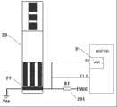
参见图2所示,公开了一种传感器试纸条20,所述传感器试纸条20具有在绝缘基底上互相平行的参比电极21、第一工作电极23和第二工作电极25,它们电气上与参比触点22、第一触点24和第二触点26互联;同时还具有导电层27等结构。不同类型的电化学生物传感器导电层27的电阻不同。电极上面固定的反应物,通过与加入的样本材料反应,产生相应于特定待测量的电荷。Referring to shown in Fig. 2, disclose a kind of sensor
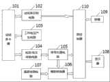
参见图3所示,本发明的电化学生物传感器测量系统包括一微控制器110,还包括一试纸条卡槽101,所述试纸条卡槽101分别连接有一用于识别不同的传感器试纸条类型的试纸条识别电路102、一用于产生电化学反应所需的工作电压的工作电压产生电路103和一用于将传感器试纸条工作电极上的电流转换成电压的电流/电压转换电路104,所述试纸条识别电路102连接至所述微控制器110,所述电流/电压转换电路104连接一信号处理电路105,所述信号处理电路105连接一模数转换器106,所述模数转换器106连接所述微控制器110,所述微控制器110连接有显示器模块108和按键模块109。Referring to Fig. 3, the electrochemical biosensor measurement system of the present invention includes a
进一步的,所述模数转换器106连接有一温度检测电路107。Further, the analog-to-
通过试纸条卡槽101实现传感器试纸条20上的参比触点22、第一触点24、第二触点26以及导电层27两端触点与电化学生物传感器测量装置的电气连接;当试纸条插入试纸条卡槽时,导电层27导通试纸条卡槽上的两个电极,引导测量装置进入测量模式;同时测量导电层的电阻,来识别电化学生物传感器的类型;工作电压产生电路利用数模转换器、模拟开关以及运算放大器等器件产生极性、幅度可变的工作电压,以适用于不同类型的试纸条;施加了工作电压,当待测样本加入后,会有流过第一工作电极23、第二工作电极25的电流,电流/电压转换电路将此电流转换为与之呈线性正相关的电压信号,电流/电压转换电路为T型网络实现的高灵敏度电流/电压转换电路;电流/电压转换电路输出的电压信号,通过信号处理电路进行放大、去噪等处理后输入到模数转换器的输入端;模数转换器将信号处理电路输入的模拟电压转换成数字量,此数字量代表了流过工作电极电流的大小;微控制器读取模数转换的结果,作去噪、校正等处理后,计算得出待测量的浓度,并将浓度及相关信息显示在显示器上;按键用于参数的设置、结果的查询等功能;温度检测电路检测温度,用于检测结果的温度系数校正;系统微控制器及其它器件均采用低功耗器件;由试纸条的插入及按键操作唤醒微控制器进入工作状态,其它绝大多数时间里处于休眠状态,并切断其它电路的电源。The
本实施方式中,微控制器110选择超低功耗微控制器MSP430。In this embodiment, the
以下,说明与本实施方式相关的电化学生物传感器测量系统的操作。Hereinafter, the operation of the electrochemical biosensor measurement system related to this embodiment will be described.
首先将传感器试纸条20插入到试纸条卡槽101中。传感器试纸条20的插入通过试纸条识别电路102起到两方面的作用:唤醒微控制器110进入工作模式,同时分压电路输出对应于不同试纸条导电层27电阻的模拟电压,由微控制器110来识别传感器试纸条20的类型。First, insert the
图4示出了试纸条识别电路的原理图。传感器试纸条20上的导电层27与阻值为R1的电阻201构成分压电路。设导电层的电阻值为Rx,则A0、P1.0点电位为 

图5示出了工作电压发生电路以及T型网络构成的电流/电压转换电路原理图。Fig. 5 shows a working voltage generating circuit and a schematic diagram of a current/voltage conversion circuit composed of a T-shaped network.
识别出传感器类型后,测量装置自适应调整工作电压。MSP430引脚P2.0控制模拟开关S1,使参比电极21的电位在Vss和2.5V之间切换。MSP430内部集成的数模转换器DAC1、DAC0的输出接到运放41、42的同相端,根据高增益运算放大器虚短路的特性,反相端电压与同相端相同,故第一工作电极23、第二工作电极25的电压即为DAC1、DAC0的输出电压。数模转换器为12位字长,取参考电压为2.5V。工作电压为工作电极与参比电极的电位差。综上所述,工作电压的调节范围为0~±2.5V,分辨率为0.61mV。After identifying the sensor type, the measuring device adaptively adjusts the operating voltage. The MSP430 pin P2.0 controls the analog switch S1 to switch the potential of the
施加工作电压、加入检测样本后,传感器内的酶和样本中相应成分发生化学反应,有与待测成分浓度相对应的电流Ia1、Ia2流过工作电极。Ia1、Ia2通过电流/电压转换电路转换成模拟电压Vdata1、Vdata2。After the working voltage is applied and the detection sample is added, the enzyme in the sensor reacts with the corresponding components in the sample, and the current Ia1 and Ia2 corresponding to the concentration of the component to be measured flow through the working electrode. Ia1 and Ia2 are converted into analog voltages Vdata1 and Vdata2 by the current/voltage conversion circuit.
图5中电路利用一种T型网络来实现高灵敏度而勿需求不切实际大的电阻。为了消除运放可能产生的振荡,而引入电阻R44、R54,其阻值很小,可以忽略。设两个数模转换器输出电压分别为VDAC1、VDAC0。The circuit in Figure 5 utilizes a T-network to achieve high sensitivity without requiring impractically large resistors. In order to eliminate the possible oscillation of the operational amplifier, resistors R44 and R54 are introduced, whose resistance value is very small and can be ignored. Suppose the output voltages of the two digital-to-analog converters are VDAC1 and VDAC0 respectively.

这个电路是靠倍乘因子来提高增益的,这样可以从一个合理的反馈电阻出发,然后乘以所需要的倍乘因子来实现高灵敏度。This circuit uses a multiplication factor to increase the gain, so you can start with a reasonable feedback resistor, and then multiply it by the required multiplication factor to achieve high sensitivity.
电流/电压转换电路的输出通过信号处理电路,即一阶低通滤波器后,输入到MSP430内部集成的模数转换器输入端,将模拟信号转换成数字量,经计算得到待测量的浓度值。The output of the current/voltage conversion circuit passes through the signal processing circuit, that is, the first-order low-pass filter, and then is input to the input terminal of the integrated analog-to-digital converter inside the MSP430, and the analog signal is converted into a digital quantity, and the concentration value to be measured is obtained by calculation .
设置温度检测电路检测环境温度,以对检测结果进行温度系数校正。温度传感器使用电压输出型的温度传感器TMP20。The temperature detection circuit is set to detect the ambient temperature, so as to correct the temperature coefficient of the detection result. As the temperature sensor, a voltage output type temperature sensor TMP20 was used.
测量结果等信息显示于显示器108上,本实施实例中采用的显示器108为MOBI2006。Information such as measurement results is displayed on the
按键模块109用于参数的设置、测量结果的查询等操作。The
MSP430通常处于LPM3低功耗模式,同时其输出的控制信号通过控制模拟开关切断其它部分电路的电源。当试纸条插入或者有按键操作时,进入中断唤醒其进入AM工作模式。这样系统的功耗被控制在了较低的水平。MSP430 is usually in LPM3 low power consumption mode, and at the same time, the control signal output by it cuts off the power supply of other parts of the circuit by controlling the analog switch. When the test strip is inserted or there is a key operation, it enters the interrupt and wakes it up to enter the AM working mode. In this way, the power consumption of the system is controlled at a lower level.
以上所述仅为本发明的优选实施例而已,并不用于限制本发明,对于本领域的技术人员来说,本发明可以有各种更改和变化。凡在本发明的精神和原则之内,所作的任何修改、等同替换、改进等,均应包含在本发明的保护范围之内。The above descriptions are only preferred embodiments of the present invention, and are not intended to limit the present invention. For those skilled in the art, the present invention may have various modifications and changes. Any modifications, equivalent replacements, improvements, etc. made within the spirit and principles of the present invention shall be included within the protection scope of the present invention.
Claims (8)
Translated fromChinesePriority Applications (1)
| Application Number | Priority Date | Filing Date | Title |
|---|---|---|---|
| CN201110247432ACN102305818A (en) | 2011-08-24 | 2011-08-24 | Measuring system for electrochemical biosensor |
Applications Claiming Priority (1)
| Application Number | Priority Date | Filing Date | Title |
|---|---|---|---|
| CN201110247432ACN102305818A (en) | 2011-08-24 | 2011-08-24 | Measuring system for electrochemical biosensor |
Publications (1)
| Publication Number | Publication Date |
|---|---|
| CN102305818Atrue CN102305818A (en) | 2012-01-04 |
Family
ID=45379699
Family Applications (1)
| Application Number | Title | Priority Date | Filing Date |
|---|---|---|---|
| CN201110247432APendingCN102305818A (en) | 2011-08-24 | 2011-08-24 | Measuring system for electrochemical biosensor |
Country Status (1)
| Country | Link |
|---|---|
| CN (1) | CN102305818A (en) |
Cited By (6)
| Publication number | Priority date | Publication date | Assignee | Title |
|---|---|---|---|---|
| CN106338596A (en)* | 2016-08-24 | 2017-01-18 | 四川长虹通信科技有限公司 | Health monitoring method, health monitoring apparatus, and electronic equipment |
| CN108872322A (en)* | 2018-08-22 | 2018-11-23 | 江苏鱼跃医疗设备股份有限公司 | With can automatic identification distinguish information test paper |
| CN111208175A (en)* | 2020-01-10 | 2020-05-29 | 三诺生物传感股份有限公司 | Sensor identification method and device and object to be tested test equipment |
| CN111751413A (en)* | 2020-05-30 | 2020-10-09 | 杭州安旭生物科技股份有限公司 | A multi-detection item testing device and method |
| CN114778631A (en)* | 2022-06-17 | 2022-07-22 | 北京华益精点生物技术有限公司 | Body index detection device and method |
| CN116559256A (en)* | 2023-04-27 | 2023-08-08 | 深圳技术大学 | Instant detection system and sensor capable of simultaneously detecting uric acid, dopamine and ascorbic acid |
Citations (5)
| Publication number | Priority date | Publication date | Assignee | Title |
|---|---|---|---|---|
| CN1419651A (en)* | 2000-03-22 | 2003-05-21 | 全麦迪科斯有限责任公司 | Electrochemical biosensor test strip with recognition electrode and readout meter using this test strip |
| CN2890916Y (en)* | 2005-09-30 | 2007-04-18 | 合世生医科技股份有限公司 | Biosensor test piece with identification function and sensor matched therewith |
| US20080112852A1 (en)* | 2002-04-25 | 2008-05-15 | Neel Gary T | Test Strips and System for Measuring Analyte Levels in a Fluid Sample |
| US20090101500A1 (en)* | 2007-10-19 | 2009-04-23 | Tien-Tsai Hsu | Test strip with identification function and test instrument using the same |
| CN101661015A (en)* | 2009-09-09 | 2010-03-03 | 上海睿兴实业有限公司 | Universal portable detector for electrochemical biosensor |
- 2011
- 2011-08-24CNCN201110247432Apatent/CN102305818A/enactivePending
Patent Citations (5)
| Publication number | Priority date | Publication date | Assignee | Title |
|---|---|---|---|---|
| CN1419651A (en)* | 2000-03-22 | 2003-05-21 | 全麦迪科斯有限责任公司 | Electrochemical biosensor test strip with recognition electrode and readout meter using this test strip |
| US20080112852A1 (en)* | 2002-04-25 | 2008-05-15 | Neel Gary T | Test Strips and System for Measuring Analyte Levels in a Fluid Sample |
| CN2890916Y (en)* | 2005-09-30 | 2007-04-18 | 合世生医科技股份有限公司 | Biosensor test piece with identification function and sensor matched therewith |
| US20090101500A1 (en)* | 2007-10-19 | 2009-04-23 | Tien-Tsai Hsu | Test strip with identification function and test instrument using the same |
| CN101661015A (en)* | 2009-09-09 | 2010-03-03 | 上海睿兴实业有限公司 | Universal portable detector for electrochemical biosensor |
Non-Patent Citations (1)
| Title |
|---|
| 佘乾顺: "微弱电流检测系统的设计与实现", 《中国优秀硕士学位论文全文数据库 信息科技辑》, no. 06, 15 June 2010 (2010-06-15)* |
Cited By (8)
| Publication number | Priority date | Publication date | Assignee | Title |
|---|---|---|---|---|
| CN106338596A (en)* | 2016-08-24 | 2017-01-18 | 四川长虹通信科技有限公司 | Health monitoring method, health monitoring apparatus, and electronic equipment |
| CN108872322A (en)* | 2018-08-22 | 2018-11-23 | 江苏鱼跃医疗设备股份有限公司 | With can automatic identification distinguish information test paper |
| CN111208175A (en)* | 2020-01-10 | 2020-05-29 | 三诺生物传感股份有限公司 | Sensor identification method and device and object to be tested test equipment |
| CN111751413A (en)* | 2020-05-30 | 2020-10-09 | 杭州安旭生物科技股份有限公司 | A multi-detection item testing device and method |
| WO2021244276A1 (en)* | 2020-05-30 | 2021-12-09 | 杭州安旭生物科技股份有限公司 | Multi-detection item test device and method |
| CN114778631A (en)* | 2022-06-17 | 2022-07-22 | 北京华益精点生物技术有限公司 | Body index detection device and method |
| CN114778631B (en)* | 2022-06-17 | 2022-12-02 | 北京华益精点生物技术有限公司 | Body index detection device and method |
| CN116559256A (en)* | 2023-04-27 | 2023-08-08 | 深圳技术大学 | Instant detection system and sensor capable of simultaneously detecting uric acid, dopamine and ascorbic acid |
Similar Documents
| Publication | Publication Date | Title |
|---|---|---|
| Kumar et al. | Environmental monitoring systems: A review | |
| CN1867826B (en) | Method and apparatus for assay of electrochemical properties | |
| US7943034B2 (en) | Method and apparatus for providing a stable voltage to an analytical system | |
| CN103399201B (en) | Universal detection chip system for weak signals of sensor | |
| CN102305818A (en) | Measuring system for electrochemical biosensor | |
| CN101975893B (en) | Differential capacitance detection circuit based on instrument amplifier and detection method thereof | |
| CN102770763B (en) | Capacitance detection in electrochemical assays | |
| CN104661593B (en) | System and method for measuring the concentration of glucose insensitive to hematocrit | |
| KR101462019B1 (en) | Blood glucose measuring instrument | |
| CN115950938B (en) | A method of manufacturing an electrochemical biosensor and an electrochemical detector | |
| CN209342650U (en) | Electrochemical-based detection device for trace elements in water environment | |
| CN115061523A (en) | A portable high-resolution potentiostatic system | |
| Trinh et al. | OPENSENS: a low-cost and multi-purpose electrochemical platform | |
| CN107045068A (en) | Portable physiological Indexs measure instrument and its detection method based on micro-fluidic paper chip | |
| Hwang et al. | CMOS VLSI potentiostat for portable environmental sensing applications | |
| US20140246335A1 (en) | Method of determining hematocrit value, quantative analysis method, and sensor chip | |
| US20190380631A1 (en) | Methods and Systems for Low Power/Low Cost Hematocrit Measurement for Blood Glucose Meter | |
| CN104684473A (en) | System and method for determining hematocrit insensitive glucose concentration | |
| CN214041538U (en) | Current and voltage detection circuit based on single chip microcomputer | |
| CN107110812A (en) | Systems and methods for electrochemical analyte measurement | |
| CN118961856A (en) | A portable, high-precision potentiostat for three-electrode electrochemical signal detection device | |
| CN205785306U (en) | A kind of hydrogen detection system based on metal-oxide gas sensor | |
| CN212341090U (en) | Heavy metal ion detection system based on microelectrode | |
| Hanson et al. | Flexible and portable electrochemical system for the detection of analytes | |
| CN102749368A (en) | Dissolved oxygen (DO) measuring system |
Legal Events
| Date | Code | Title | Description |
|---|---|---|---|
| C06 | Publication | ||
| PB01 | Publication | ||
| C10 | Entry into substantive examination | ||
| SE01 | Entry into force of request for substantive examination | ||
| C02 | Deemed withdrawal of patent application after publication (patent law 2001) | ||
| WD01 | Invention patent application deemed withdrawn after publication | Application publication date:20120104 |