CN102300593A - Porous skin with increased surface roughness and implant bonded thereto - Google Patents
Porous skin with increased surface roughness and implant bonded theretoDownload PDFInfo
- Publication number
- CN102300593A CN102300593ACN200980153743XACN200980153743ACN102300593ACN 102300593 ACN102300593 ACN 102300593ACN 200980153743X ACN200980153743X ACN 200980153743XACN 200980153743 ACN200980153743 ACN 200980153743ACN 102300593 ACN102300593 ACN 102300593A
- Authority
- CN
- China
- Prior art keywords
- powder
- machined
- metal foam
- porous
- machining
- Prior art date
- Legal status (The legal status is an assumption and is not a legal conclusion. Google has not performed a legal analysis and makes no representation as to the accuracy of the status listed.)
- Granted
Links
Images


Classifications
- A—HUMAN NECESSITIES
- A61—MEDICAL OR VETERINARY SCIENCE; HYGIENE
- A61F—FILTERS IMPLANTABLE INTO BLOOD VESSELS; PROSTHESES; DEVICES PROVIDING PATENCY TO, OR PREVENTING COLLAPSING OF, TUBULAR STRUCTURES OF THE BODY, e.g. STENTS; ORTHOPAEDIC, NURSING OR CONTRACEPTIVE DEVICES; FOMENTATION; TREATMENT OR PROTECTION OF EYES OR EARS; BANDAGES, DRESSINGS OR ABSORBENT PADS; FIRST-AID KITS
- A61F2/00—Filters implantable into blood vessels; Prostheses, i.e. artificial substitutes or replacements for parts of the body; Appliances for connecting them with the body; Devices providing patency to, or preventing collapsing of, tubular structures of the body, e.g. stents
- A61F2/02—Prostheses implantable into the body
- A61F2/30—Joints
- A61F2/3094—Designing or manufacturing processes
- A—HUMAN NECESSITIES
- A61—MEDICAL OR VETERINARY SCIENCE; HYGIENE
- A61F—FILTERS IMPLANTABLE INTO BLOOD VESSELS; PROSTHESES; DEVICES PROVIDING PATENCY TO, OR PREVENTING COLLAPSING OF, TUBULAR STRUCTURES OF THE BODY, e.g. STENTS; ORTHOPAEDIC, NURSING OR CONTRACEPTIVE DEVICES; FOMENTATION; TREATMENT OR PROTECTION OF EYES OR EARS; BANDAGES, DRESSINGS OR ABSORBENT PADS; FIRST-AID KITS
- A61F2/00—Filters implantable into blood vessels; Prostheses, i.e. artificial substitutes or replacements for parts of the body; Appliances for connecting them with the body; Devices providing patency to, or preventing collapsing of, tubular structures of the body, e.g. stents
- A61F2/02—Prostheses implantable into the body
- A61F2/28—Bones
- A—HUMAN NECESSITIES
- A61—MEDICAL OR VETERINARY SCIENCE; HYGIENE
- A61F—FILTERS IMPLANTABLE INTO BLOOD VESSELS; PROSTHESES; DEVICES PROVIDING PATENCY TO, OR PREVENTING COLLAPSING OF, TUBULAR STRUCTURES OF THE BODY, e.g. STENTS; ORTHOPAEDIC, NURSING OR CONTRACEPTIVE DEVICES; FOMENTATION; TREATMENT OR PROTECTION OF EYES OR EARS; BANDAGES, DRESSINGS OR ABSORBENT PADS; FIRST-AID KITS
- A61F2/00—Filters implantable into blood vessels; Prostheses, i.e. artificial substitutes or replacements for parts of the body; Appliances for connecting them with the body; Devices providing patency to, or preventing collapsing of, tubular structures of the body, e.g. stents
- A61F2/02—Prostheses implantable into the body
- A61F2/30—Joints
- A—HUMAN NECESSITIES
- A61—MEDICAL OR VETERINARY SCIENCE; HYGIENE
- A61L—METHODS OR APPARATUS FOR STERILISING MATERIALS OR OBJECTS IN GENERAL; DISINFECTION, STERILISATION OR DEODORISATION OF AIR; CHEMICAL ASPECTS OF BANDAGES, DRESSINGS, ABSORBENT PADS OR SURGICAL ARTICLES; MATERIALS FOR BANDAGES, DRESSINGS, ABSORBENT PADS OR SURGICAL ARTICLES
- A61L27/00—Materials for grafts or prostheses or for coating grafts or prostheses
- A61L27/50—Materials characterised by their function or physical properties, e.g. injectable or lubricating compositions, shape-memory materials, surface modified materials
- A61L27/56—Porous materials, e.g. foams or sponges
- A—HUMAN NECESSITIES
- A61—MEDICAL OR VETERINARY SCIENCE; HYGIENE
- A61F—FILTERS IMPLANTABLE INTO BLOOD VESSELS; PROSTHESES; DEVICES PROVIDING PATENCY TO, OR PREVENTING COLLAPSING OF, TUBULAR STRUCTURES OF THE BODY, e.g. STENTS; ORTHOPAEDIC, NURSING OR CONTRACEPTIVE DEVICES; FOMENTATION; TREATMENT OR PROTECTION OF EYES OR EARS; BANDAGES, DRESSINGS OR ABSORBENT PADS; FIRST-AID KITS
- A61F2/00—Filters implantable into blood vessels; Prostheses, i.e. artificial substitutes or replacements for parts of the body; Appliances for connecting them with the body; Devices providing patency to, or preventing collapsing of, tubular structures of the body, e.g. stents
- A61F2/02—Prostheses implantable into the body
- A61F2/30—Joints
- A61F2/38—Joints for elbows or knees
- A61F2/3859—Femoral components
- A—HUMAN NECESSITIES
- A61—MEDICAL OR VETERINARY SCIENCE; HYGIENE
- A61F—FILTERS IMPLANTABLE INTO BLOOD VESSELS; PROSTHESES; DEVICES PROVIDING PATENCY TO, OR PREVENTING COLLAPSING OF, TUBULAR STRUCTURES OF THE BODY, e.g. STENTS; ORTHOPAEDIC, NURSING OR CONTRACEPTIVE DEVICES; FOMENTATION; TREATMENT OR PROTECTION OF EYES OR EARS; BANDAGES, DRESSINGS OR ABSORBENT PADS; FIRST-AID KITS
- A61F2/00—Filters implantable into blood vessels; Prostheses, i.e. artificial substitutes or replacements for parts of the body; Appliances for connecting them with the body; Devices providing patency to, or preventing collapsing of, tubular structures of the body, e.g. stents
- A61F2/02—Prostheses implantable into the body
- A61F2/30—Joints
- A61F2/38—Joints for elbows or knees
- A61F2/389—Tibial components
- A—HUMAN NECESSITIES
- A61—MEDICAL OR VETERINARY SCIENCE; HYGIENE
- A61F—FILTERS IMPLANTABLE INTO BLOOD VESSELS; PROSTHESES; DEVICES PROVIDING PATENCY TO, OR PREVENTING COLLAPSING OF, TUBULAR STRUCTURES OF THE BODY, e.g. STENTS; ORTHOPAEDIC, NURSING OR CONTRACEPTIVE DEVICES; FOMENTATION; TREATMENT OR PROTECTION OF EYES OR EARS; BANDAGES, DRESSINGS OR ABSORBENT PADS; FIRST-AID KITS
- A61F2/00—Filters implantable into blood vessels; Prostheses, i.e. artificial substitutes or replacements for parts of the body; Appliances for connecting them with the body; Devices providing patency to, or preventing collapsing of, tubular structures of the body, e.g. stents
- A61F2/02—Prostheses implantable into the body
- A61F2/30—Joints
- A61F2/44—Joints for the spine, e.g. vertebrae, spinal discs
- A—HUMAN NECESSITIES
- A61—MEDICAL OR VETERINARY SCIENCE; HYGIENE
- A61F—FILTERS IMPLANTABLE INTO BLOOD VESSELS; PROSTHESES; DEVICES PROVIDING PATENCY TO, OR PREVENTING COLLAPSING OF, TUBULAR STRUCTURES OF THE BODY, e.g. STENTS; ORTHOPAEDIC, NURSING OR CONTRACEPTIVE DEVICES; FOMENTATION; TREATMENT OR PROTECTION OF EYES OR EARS; BANDAGES, DRESSINGS OR ABSORBENT PADS; FIRST-AID KITS
- A61F2/00—Filters implantable into blood vessels; Prostheses, i.e. artificial substitutes or replacements for parts of the body; Appliances for connecting them with the body; Devices providing patency to, or preventing collapsing of, tubular structures of the body, e.g. stents
- A61F2/02—Prostheses implantable into the body
- A61F2/30—Joints
- A61F2/30767—Special external or bone-contacting surface, e.g. coating for improving bone ingrowth
- A61F2002/3092—Special external or bone-contacting surface, e.g. coating for improving bone ingrowth having an open-celled or open-pored structure
- A—HUMAN NECESSITIES
- A61—MEDICAL OR VETERINARY SCIENCE; HYGIENE
- A61F—FILTERS IMPLANTABLE INTO BLOOD VESSELS; PROSTHESES; DEVICES PROVIDING PATENCY TO, OR PREVENTING COLLAPSING OF, TUBULAR STRUCTURES OF THE BODY, e.g. STENTS; ORTHOPAEDIC, NURSING OR CONTRACEPTIVE DEVICES; FOMENTATION; TREATMENT OR PROTECTION OF EYES OR EARS; BANDAGES, DRESSINGS OR ABSORBENT PADS; FIRST-AID KITS
- A61F2/00—Filters implantable into blood vessels; Prostheses, i.e. artificial substitutes or replacements for parts of the body; Appliances for connecting them with the body; Devices providing patency to, or preventing collapsing of, tubular structures of the body, e.g. stents
- A61F2/02—Prostheses implantable into the body
- A61F2/30—Joints
- A61F2/3094—Designing or manufacturing processes
- A61F2002/30968—Sintering
- A—HUMAN NECESSITIES
- A61—MEDICAL OR VETERINARY SCIENCE; HYGIENE
- A61F—FILTERS IMPLANTABLE INTO BLOOD VESSELS; PROSTHESES; DEVICES PROVIDING PATENCY TO, OR PREVENTING COLLAPSING OF, TUBULAR STRUCTURES OF THE BODY, e.g. STENTS; ORTHOPAEDIC, NURSING OR CONTRACEPTIVE DEVICES; FOMENTATION; TREATMENT OR PROTECTION OF EYES OR EARS; BANDAGES, DRESSINGS OR ABSORBENT PADS; FIRST-AID KITS
- A61F2310/00—Prostheses classified in A61F2/28 or A61F2/30 - A61F2/44 being constructed from or coated with a particular material
- A61F2310/00005—The prosthesis being constructed from a particular material
- A61F2310/00011—Metals or alloys
- A61F2310/00029—Cobalt-based alloys, e.g. Co-Cr alloys or Vitallium
- A—HUMAN NECESSITIES
- A61—MEDICAL OR VETERINARY SCIENCE; HYGIENE
- A61F—FILTERS IMPLANTABLE INTO BLOOD VESSELS; PROSTHESES; DEVICES PROVIDING PATENCY TO, OR PREVENTING COLLAPSING OF, TUBULAR STRUCTURES OF THE BODY, e.g. STENTS; ORTHOPAEDIC, NURSING OR CONTRACEPTIVE DEVICES; FOMENTATION; TREATMENT OR PROTECTION OF EYES OR EARS; BANDAGES, DRESSINGS OR ABSORBENT PADS; FIRST-AID KITS
- A61F2310/00—Prostheses classified in A61F2/28 or A61F2/30 - A61F2/44 being constructed from or coated with a particular material
- A61F2310/00005—The prosthesis being constructed from a particular material
- A61F2310/00011—Metals or alloys
- A61F2310/00035—Other metals or alloys
- A61F2310/00089—Zirconium or Zr-based alloys
- A—HUMAN NECESSITIES
- A61—MEDICAL OR VETERINARY SCIENCE; HYGIENE
- A61F—FILTERS IMPLANTABLE INTO BLOOD VESSELS; PROSTHESES; DEVICES PROVIDING PATENCY TO, OR PREVENTING COLLAPSING OF, TUBULAR STRUCTURES OF THE BODY, e.g. STENTS; ORTHOPAEDIC, NURSING OR CONTRACEPTIVE DEVICES; FOMENTATION; TREATMENT OR PROTECTION OF EYES OR EARS; BANDAGES, DRESSINGS OR ABSORBENT PADS; FIRST-AID KITS
- A61F2310/00—Prostheses classified in A61F2/28 or A61F2/30 - A61F2/44 being constructed from or coated with a particular material
- A61F2310/00005—The prosthesis being constructed from a particular material
- A61F2310/00011—Metals or alloys
- A61F2310/00035—Other metals or alloys
- A61F2310/00131—Tantalum or Ta-based alloys
- A—HUMAN NECESSITIES
- A61—MEDICAL OR VETERINARY SCIENCE; HYGIENE
- A61L—METHODS OR APPARATUS FOR STERILISING MATERIALS OR OBJECTS IN GENERAL; DISINFECTION, STERILISATION OR DEODORISATION OF AIR; CHEMICAL ASPECTS OF BANDAGES, DRESSINGS, ABSORBENT PADS OR SURGICAL ARTICLES; MATERIALS FOR BANDAGES, DRESSINGS, ABSORBENT PADS OR SURGICAL ARTICLES
- A61L2400/00—Materials characterised by their function or physical properties
- A61L2400/18—Modification of implant surfaces in order to improve biocompatibility, cell growth, fixation of biomolecules, e.g. plasma treatment
- A—HUMAN NECESSITIES
- A61—MEDICAL OR VETERINARY SCIENCE; HYGIENE
- A61L—METHODS OR APPARATUS FOR STERILISING MATERIALS OR OBJECTS IN GENERAL; DISINFECTION, STERILISATION OR DEODORISATION OF AIR; CHEMICAL ASPECTS OF BANDAGES, DRESSINGS, ABSORBENT PADS OR SURGICAL ARTICLES; MATERIALS FOR BANDAGES, DRESSINGS, ABSORBENT PADS OR SURGICAL ARTICLES
- A61L27/00—Materials for grafts or prostheses or for coating grafts or prostheses
- A61L27/28—Materials for coating prostheses
- A61L27/30—Inorganic materials
- A61L27/306—Other specific inorganic materials not covered by A61L27/303 - A61L27/32
- Y—GENERAL TAGGING OF NEW TECHNOLOGICAL DEVELOPMENTS; GENERAL TAGGING OF CROSS-SECTIONAL TECHNOLOGIES SPANNING OVER SEVERAL SECTIONS OF THE IPC; TECHNICAL SUBJECTS COVERED BY FORMER USPC CROSS-REFERENCE ART COLLECTIONS [XRACs] AND DIGESTS
- Y10—TECHNICAL SUBJECTS COVERED BY FORMER USPC
- Y10T—TECHNICAL SUBJECTS COVERED BY FORMER US CLASSIFICATION
- Y10T156/00—Adhesive bonding and miscellaneous chemical manufacture
- Y10T156/10—Methods of surface bonding and/or assembly therefor
Landscapes
- Health & Medical Sciences (AREA)
- Life Sciences & Earth Sciences (AREA)
- Public Health (AREA)
- Veterinary Medicine (AREA)
- Oral & Maxillofacial Surgery (AREA)
- Transplantation (AREA)
- Animal Behavior & Ethology (AREA)
- General Health & Medical Sciences (AREA)
- Engineering & Computer Science (AREA)
- Chemical & Material Sciences (AREA)
- Biomedical Technology (AREA)
- Vascular Medicine (AREA)
- Heart & Thoracic Surgery (AREA)
- Cardiology (AREA)
- Orthopedic Medicine & Surgery (AREA)
- Dispersion Chemistry (AREA)
- Dermatology (AREA)
- Medicinal Chemistry (AREA)
- Epidemiology (AREA)
- Manufacturing & Machinery (AREA)
- Prostheses (AREA)
- Materials For Medical Uses (AREA)
- Powder Metallurgy (AREA)
Abstract
Description
Translated fromChinese相关申请的交互参考Cross-References to Related Applications
本申请要求2008年10月29日提交的、美国临时申请号61/109,395的权利。这篇先前的申请的公开内容通过全文参考结合于本文。This application claims the benefit of US Provisional Application No. 61/109,395, filed October 29, 2008. The disclosure of this prior application is incorporated herein by reference in its entirety.
发明背景Background of the invention
发明领域field of invention
本发明一般涉及具有增加的粗糙度的表层,且更具体地涉及用于增加多孔结构的组织啮合(tissue-engaging)外表面的粗糙度而不改变所述结构的孔径(pore size)和孔隙度的方法,以及涉及将增加粗糙度的表面的整合入所述多孔结构的医用植入物。The present invention relates generally to surfaces with increased roughness, and more particularly to methods for increasing the roughness of the tissue-engaging outer surface of a porous structure without changing the pore size and porosity of the structure A method, and a medical implant involving the integration of a surface of increased roughness into the porous structure.
相关技术的描述Description of related technologies
特别是在医学领域中,植入物、装置或其它器具的表面可显著影响功能。例如,已作尝试通过提高植入物的粗糙度改善骨植入物稳定性。也已作其它尝试通过在植入物中提供骨长入(bone ingrowth)的小孔改善骨植入物稳定性。Especially in the medical field, the surface of an implant, device or other appliance can significantly affect the function. For example, attempts have been made to improve bone implant stability by increasing the roughness of the implant. Other attempts have also been made to improve bone implant stability by providing small holes in the implant for bone ingrowth.
一种在接触骨的植入物(如,整形外科植入物)中实现骨长入方法包括将金属性珠表面烧结在基底上。在植入物中实现骨长入的其它方法包括采用由钛构建的网状泡沫多孔涂层(其结合放电机械加工的(EDM)表面处理)、具有轴向沟槽的EDM表面、具有交叉影线(crosshatching)的EDM表面或光蚀刻表面。泡沫金属植入物已经显示达到比烧结的珠植入物更大的骨内生性(ingrowth)。参见,Urban,Robert M.等,“对新泡沫金属多孔涂层的生物机理和组织学应答,两种测量骨长入的测量方法的比较(Biomechanical and Histological Response to aNovel Foam Metal Porous Coating with Comparison of Two Methods forMeasuring Bone Ingrowth)”,整形外科的研究学会第54期年会学报,第1854页,2008年3月2-5日。One method of achieving bone ingrowth in a bone-contacting implant (eg, an orthopedic implant) includes sintering a metallic bead surface on a substrate. Other approaches to achieve bone ingrowth in implants include the use of reticulated foam porous coatings constructed of titanium in combination with electrical discharge machined (EDM) surface treatments, EDM surfaces with axial grooves, cross-hatched EDM surface or photoetched surface for crosshatching. Metal foam implants have been shown to achieve greater bone ingrowth than sintered bead implants. See, Urban, Robert M. et al., "Biomechanical and Histological Response to a Novel Foam Metal Porous Coating with Comparison of Two Methods for Measuring Bone Ingrowth), Proceedings of the 54th Annual Meeting of the Society for Research in Plastic Surgery, p. 1854, March 2-5, 2008.
然而,产生多孔金属泡沫向内成长结构(如,由将细微金属粉末粒子施用于多孔结构的所有表面创造的结构)可需要第二个机械加工步骤,以得到机械加工的金属泡沫结构的想要的形状和尺寸(如,公差(tolerances))。这样的机械加工可引起机械加工表面(如,组织-啮合的外表面)上的粗糙度丢失。可采用有纹理的模具在烧结过程中将压力-烧结粒子烧结至基底上,而不牺牲用于多孔珠-涂布的植入物的纹理,以维持或复原粗糙度。或者,采用放电机械加工(“EDM”),造成交叉影线图(cross hatch pattern),并且当植入时,在涂层和骨中的凹槽之间造成缝隙,可维持或复原金属性泡沫的粗糙度。因此已经证明在维持结构的孔径和孔隙度的同时,这些机制在增加多孔金属泡沫长入结构的机械加工的组织-啮合的外表面的粗糙度中是不令人满意的。However, producing a porous metal foam ingrowth structure (e.g., a structure created by applying fine metal powder particles to all surfaces of the porous structure) may require a second machining step to obtain the desired machined metal foam structure. shape and size (eg, tolerances). Such machining can cause a loss of roughness on the machined surface (eg, tissue-engaging outer surface). A textured mold can be used to sinter pressure-sintered particles onto a substrate during sintering without sacrificing texture for porous bead-coated implants to maintain or restore roughness. Alternatively, electrical discharge machining ("EDM"), which creates a cross hatch pattern and, when implanted, creates a gap between the coating and the groove in the bone, maintains or restores the metallic foam roughness. These mechanisms have thus proven unsatisfactory in increasing the roughness of the machined tissue-engaging outer surface of the porous metal foam ingrowth into the structure while maintaining the pore size and porosity of the structure.
因此,存在着一种改良的方法的需求,以提供具有避免以上讨论的缺点的改良的骨长入特性的多孔金属泡沫结构。Accordingly, a need exists for an improved method of providing porous metal foam structures with improved bone ingrowth properties that avoid the disadvantages discussed above.
发明简述Brief description of the invention
本发明的实施方案涉及增加多孔结构的经机械加工的组织接口外表面的表面粗糙度而不改变多孔结构的孔径或孔隙度。Embodiments of the present invention relate to increasing the surface roughness of the machined tissue-interfacing outer surface of a porous structure without changing the pore size or porosity of the porous structure.
在一个实施方案中,假体植入物包括机械加工的网状多孔结构。可将包括不对称粒子的粉末布置在多孔结构的经机械加工的组织接口外表面上。在多孔结构中的所述不对称粒子可具有约30%和约70%之间的孔径大小,以至于增加植入物的经机械加工的组织接口外表面的表面粗糙度,而同时基本抑制多孔结构的开口小孔的闭塞和/或基本没有修改多孔结构的孔隙度。在一个实施方案中,多孔结构可为多孔金属体。类似地,在一个实施方案中,粉末可为金属粉末。在其它的实施方案中,多孔结构和粉末可具有非-金属材料。In one embodiment, the prosthetic implant comprises a machined mesh porous structure. A powder comprising asymmetric particles can be disposed on the outer surface of the machined tissue interface of the porous structure. The asymmetric particles in the porous structure may have a pore size of between about 30% and about 70% so as to increase the surface roughness of the machined tissue interface outer surface of the implant while substantially inhibiting the porous structure Closure of the open pores and/or the porosity of the porous structure does not substantially modify. In one embodiment, the porous structure may be a porous metal body. Similarly, in one embodiment, the powder may be a metal powder. In other embodiments, the porous structure and powder may have non-metallic materials.
在另一个实施方案中,假体植入物包括先前已机械加工的网状多孔结构,在先前已机械加工的网状多孔结构的全部表面上已经施用了一层或更多层额外的粉末层。可将含不对称粒子的粉末布置在多孔结构的先前已经机械加工的组织接口外表面上。在多孔结构中的不对称粒子可具有约30%和约70%之间孔径的大小,以便增加植入物的先前已经机械加工的组织接口外表面的表面粗糙度,而同时基本抑制多孔结构的开口小孔的闭塞和/或基本不修改多孔结构的孔隙度。In another embodiment, the prosthetic implant comprises a previously machined reticulated porous structure to which one or more additional powder layers have been applied over the entire surface of the previously machined reticulated porous structure . The asymmetric particle-containing powder can be disposed on the previously machined tissue interface exterior surface of the porous structure. The asymmetric particles in the porous structure may have a size of between about 30% and about 70% of the pore diameter so as to increase the surface roughness of the previously machined tissue interface outer surface of the implant while substantially inhibiting the opening of the porous structure Occlusion of the pores and/or does not substantially modify the porosity of the porous structure.
依据另一个实施方案,提供包含施用于固体表面的机械加工的网状多孔构造(porous construct)的假体植入物。可将含不对称粉末粒子的粉末附着于多孔构造的经机械加工的组织接口外表面。粉末的粒度被设定为增加多孔构造的经机械加工的组织接口外表面的表面粗糙度,而同时基本维持多孔构造的小孔开口。According to another embodiment, a prosthetic implant comprising a machined mesh porous construct applied to a solid surface is provided. A powder comprising asymmetric powder particles can be attached to the outer surface of the machined tissue interface of the porous construct. The particle size of the powder is sized to increase the surface roughness of the machined tissue interface outer surface of the porous construct while substantially maintaining the pore openings of the porous construct.
依据还一个实施方案,提供包含先前已经机械加工的网状多孔构造的假体植入物,在所述构造的全部表面上已施用一层或更多层额外的粉末层并将该构造施用于固体表面。可将包含不对称粉末粒子的粉末附着于多孔构造的先前已经机械加工的组织接口外表面上。不对称粒子的粉末的粒度被设定为增加多孔构造的先前已经机械加工的组织接口外表面的表面粗糙度,而同时基本维持多孔构造的小孔开口。According to yet another embodiment, there is provided a prosthetic implant comprising a previously machined reticulated porous construction to which one or more additional powder layers have been applied on all surfaces of said construction and applied to solid surface. A powder comprising asymmetric powder particles can be attached to the previously machined tissue interface exterior surface of the porous construct. The powder of asymmetric particles is sized to increase the surface roughness of the previously machined tissue interface outer surface of the porous construct while substantially maintaining the pore openings of the porous construct.
依据又一个实施方案,提供包含机械加工的网状结构和粘合至网状结构的经机械加工的组织接口外表面的粉末的表层。所述粉末包含具有约75微米和约106微米之间大小的不对称钛粒子。According to yet another embodiment, there is provided a skin comprising a machined mesh structure and a powder bonded to the machined tissue-interfacing outer surface of the mesh structure. The powder comprises asymmetric titanium particles having a size between about 75 microns and about 106 microns.
依据另一个实施方案,提供包含先前已机械加工的网状结构组成的表层,所述先前已经机械加工的网状结构的全部表面上已施用一层或更多层额外的粉末层。可将包含具有约75微米和约106微米之间粒径的不对称钛粒子的粉末粘合至网状结构的经机械加工的组织接口外表面。According to another embodiment, there is provided a skin comprising a previously machined network consisting of one or more additional powder layers applied to the entire surface of said previously machined network. A powder comprising asymmetric titanium particles having a particle size between about 75 microns and about 106 microns may be bonded to the machined tissue interface outer surface of the mesh structure.
依据另外的又一个实施方案,提供用于增加多孔结构的表面粗糙度的方法。该方法包括将多孔结构机械加工为想要的形状和将包含不对称粉末粒子的粉末粘合至机械加工的多孔结构的经机械加工的组织接口外表面。将粉末粒子的大小设定为增加机械加工的多孔结构的经机械加工的组织接口外表面的粗糙度,而同时防止多孔结构的小孔的闭塞和/或维持多孔结构的孔隙度。在一个实施方案中,多孔结构为多孔金属泡沫和该粉末包含金属性粉末。在另一个实施方案中,多孔结构和粉末具有非-金属性材料。According to yet another embodiment, a method for increasing the surface roughness of a porous structure is provided. The method includes machining a porous structure into a desired shape and bonding a powder comprising asymmetric powder particles to a machined tissue-interfacing outer surface of the machined porous structure. The powder particles are sized to increase the roughness of the machined tissue interface outer surface of the machined porous structure while simultaneously preventing occlusion of the pores of the porous structure and/or maintaining the porosity of the porous structure. In one embodiment, the porous structure is a porous metal foam and the powder comprises a metallic powder. In another embodiment, the porous structure and powder are of non-metallic material.
依据再一个实施方案,提供用于增加多孔结构的表面粗糙度的方法。该方法包括将多孔结构机械加工为想要的形状和将一层或更多层额外的粉末层施用于多孔结构的全部表面。该方法还包括将包含不对称粉末粒子的粉末粘合至机械加工的多孔结构的先前已经机械加工的组织接口外表面上。所述粉末粒子的大小设定为增加机械加工的多孔结构的先前已经机械加工的组织接口外表面的粗糙度,而同时防止多孔结构的小孔闭塞和/或维持多孔结构的孔隙度。According to yet another embodiment, a method for increasing the surface roughness of a porous structure is provided. The method includes machining the porous structure into a desired shape and applying one or more additional powder layers to the entire surface of the porous structure. The method also includes adhering a powder comprising asymmetric powder particles to a previously machined tissue interface outer surface of the machined porous structure. The powder particles are sized to increase the roughness of the previously machined tissue interface outer surface of the machined porous structure while simultaneously preventing occlusion of the pores of the porous structure and/or maintaining the porosity of the porous structure.
图的简述Brief description of the graph
将在下文以参考图而详细解释的实施例实施方案的方式描述本发明,其中:The invention will be described hereinafter by way of example embodiments explained in detail with reference to the drawings, in which:
图1描绘在先技术的烧结金属泡沫预加工件(pre-form)的放大图像。采用以下步骤形成图1中显示的烧结金属泡沫预加工件:1)提供60ppi聚氨酯(PU)泡沫骨架,2)使用粘合剂,将三层细微球形金属粉末(如,球形钛粉末)涂布在所述60ppi聚氨酯(PU)泡沫骨架的全部表面制成“预加工的A”,3)随后从如参考表1于50x放大倍数下描述的“预加工的A”烧尽(burning out)PU骨架,形成绿色金属泡沫,4)随后采用电火花线切割(wire electrical discharge machining)(WEDM)方法将所述绿色金属泡沫经机械加工为要求的形状,以及,然后5)随后烧结经机械加工的绿色金属泡沫以形成所述在先技术的烧结金属泡沫预加工件;Figure 1 depicts an enlarged image of a prior art sintered metal foam pre-form. The following steps were used to form the sintered metal foam preform shown in Figure 1: 1) provide a 60ppi polyurethane (PU) foam backbone, 2) apply three layers of finely spherical metal powder (e.g., spherical titanium powder) using a binder "Preprocessed A" was made on the entire surface of the 60ppi polyurethane (PU) foam backbone, 3) the PU was subsequently burned out from "Preprocessed A" as described with reference to Table 1 at 50x magnification skeleton, forming the green metal foam, 4) subsequently machining the green metal foam into the desired shape using wire electrical discharge machining (WEDM) methods, and, then 5) subsequently sintering the machined green metal foam to form said prior art sintered metal foam preform;
图2描绘依据本发明的一个实施方案的改良的烧结金属泡沫预加工件的放大图像。可采用以下步骤形成图2中显示的改良的烧结金属泡沫预加工件:1)提供60ppi聚氨酯(PU)泡沫骨架,2)使用粘合剂,将两层细微球形金属粉末(如,球形Ti粉)涂布在所述60ppi PU泡沫骨架的全部表面,3)随后从得到的构造烧尽PU骨架以形成绿色金属泡沫,4)随后采用电火花线切割(WEDM)方法或类似的方法将所述绿色金属泡沫经机械加工为要求的形状,以形成机械加工的绿色金属泡沫,5)随后将另外一层细微球形金属粉末(如,球形Ti粉)施加于所述机械加工的绿色金属泡沫的全部表面,以形成如参考表1于50x放大倍数下描述的“预加工的B”,以及,然后6)随后烧结预加工的B以形成所述改良的烧结金属泡沫;Figure 2 depicts an enlarged image of an improved sintered metal foam preform according to one embodiment of the present invention. The modified sintered metal foam preform shown in Figure 2 can be formed using the following steps: 1) providing a 60ppi polyurethane (PU) foam backbone, 2) using a binder, two layers of finely spherical metal powder (e.g., spherical Ti powder) ) coating the entire surface of the 60ppi PU foam backbone, 3) subsequently burning out the PU backbone from the resulting construction to form a green metallic foam, 4) subsequently cutting the PU foam using a wire electric discharge (WEDM) method or similar The green metal foam is machined into the desired shape to form the machined green metal foam, 5) another layer of fine spherical metal powder (e.g., spherical Ti powder) is then applied to the entirety of the machined green metal foam surface, to form "preprocessed B" as described under 50x magnification with reference to Table 1, and, then 6) subsequent sintering of preprocessed B to form the modified sintered metal foam;
图3描绘依据本发明另一个实施方案的“粗糙的金属泡沫”的放大图像。可采用以下步形成“粗糙的金属泡沫”:1)提供如上讨论的“预加工的A”,2)采用电火花线切割(WEDM)方法或类似的方法将“预加工的A”机械加工为要求的形状,其中的机械加工步骤形成至少一个经机械加工的组织接口外表面,3)如参考表1于50x放大倍数下描述的,将至少一层不对称金属粉末粒子(如,钛或脱氢Ti(Ti dehydride)粒子)施加于所述至少一个经机械加工的组织接口外表面上,和4)烧结得到的构造,以形成所述“粗糙的金属泡沫”;Figure 3 depicts a magnified image of a "rough metal foam" according to another embodiment of the present invention. The "rough metal foam" can be formed using the following steps: 1) providing the "pre-machined A" as discussed above, 2) machining the "pre-machined A" into desired shape, wherein the machining step forms at least one machined outer surface of the tissue interface, 3) as described with reference to Table 1 at 50x magnification, at least one layer of asymmetric metal powder particles (e.g., titanium or hydrogen Ti (Ti dehydrate) particles) applied to said at least one machined tissue interface outer surface, and 4) sintering the resulting construct to form said "rough metal foam";
图4是图3的粗糙的金属泡沫的横截面的放大图像,于50x放大倍数下(大图)和85x放大倍数(插入图像)显示具有粗糙的组织接口外表面的粗糙的多孔金属泡沫结构;Figure 4 is a magnified image of a cross-section of the rough metal foam of Figure 3 showing a rough porous metal foam structure with a rough tissue interface outer surface at 50x magnification (large image) and 85x magnification (insert image);
图5分别描绘如参考表2描述的“预加工的A”、“预加工的B”和“粗糙的金属泡沫”的组织接口外表面的地形起伏图(topographicalrelief map);5 depicts topographical relief maps of the tissue interface outer surfaces of "Preprocessed A", "Preprocessed B" and "Rough Metal Foam", respectively, as described with reference to Table 2;
图6显示参考表4、采用(A)60ppi起始聚氨酯泡沫和(B)45ppi起始聚氨酯泡沫生产的机械加工和烧结金属泡沫的SEM图像(25X)。Figure 6 shows SEM images (25X) of machined and sintered metal foams produced with reference to Table 4 using (A) 60 ppi starting polyurethane foam and (B) 45 ppi starting polyurethane foam.
图7描绘用于制备具有粗糙度增加的组织-啮合的外表面的多孔泡沫结构的方法的一个实施方案。Figure 7 depicts one embodiment of a method for preparing a cellular foam structure with a tissue-engaging outer surface of increased roughness.
图8描绘用于制备具有粗糙度增加的组织-啮合的外表面的多孔泡沫结构而没有影响多孔结构的孔隙度和孔径的方法的另一个实施方案。8 depicts another embodiment of a method for preparing a porous foam structure with a tissue-engaging outer surface of increased roughness without affecting the porosity and pore size of the porous structure.
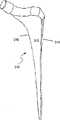
图9描绘具有粗糙的组织接口外表面的髋关节假体的股骨干的实施方案;Figure 9 depicts an embodiment of the femoral shaft of a hip prosthesis with a rough tissue interface outer surface;
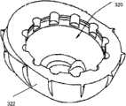
图10描绘具有粗糙的组织接口外表面的髋关节假体的髋臼杯(acetabular shell)的实施方案;Fig. 10 depicts the embodiment of the acetabular cup (acetabular shell) of the hip joint prosthesis with rough tissue interface outer surface;
图11描绘具有粗糙的组织接口外表面的肩关节假体的实施方案;和11 depicts an embodiment of a shoulder prosthesis with a rough tissue interface outer surface; and
图12描绘具有组织接口外部的膝关节假体的一个实施方案。Figure 12 depicts one embodiment of a knee prosthesis with a tissue interface exterior.
优选实施方案的详述DETAILED DESCRIPTION OF THE PREFERRED EMBODIMENT
本文公开的实施方案提供在结构的经机械加工的组织接口外表面上具有表面粗糙度增加的多孔结构和制作其的方法。经机械加工的组织接口外表面一般得益于由将粉末施用于多孔结构(如,多孔金属体、多孔泡沫材料)造成的增加的粗糙度。Embodiments disclosed herein provide porous structures having increased surface roughness on the machined tissue-interfacing outer surface of the structures and methods of making the same. Machined tissue interface exterior surfaces generally benefit from increased roughness resulting from powder application to porous structures (eg, porous metal bodies, porous foams).
一般地,可将具有粗糙度增加的组织接口外表面施用于多孔金属性结构,一种形成的结构,预加工的结构或同样的其它物体的表面。在医用物品的情况下,生物惰性材料,诸如钛、钛合金、钽、钽合金、钴-铬合金、锆、锆合金等可用于多孔结构。然而,可使用其它适宜的金属性和非-金属性材料。这样的非-金属性材料可包括骨导电陶瓷(osteoconductive ceramics),诸如,例如,磷酸钙(如,α和β磷酸三钙、羟磷灰石等)。可按任何已知的方式使该材料模压、机械加工或加工成所需的形状。再有,材料可为固体、呈现为泡沫形式(诸如,例如,聚氨酯泡沫)或泡沫,其先前已施用于如由钛、钛合金、钽、钽合金、钴-铬合金、锆、锆合金或其它适宜的金属性和非-金属性材料组成的固体金属基底上。In general, a tissue-interfacing outer surface having an increased roughness can be applied to the surface of a porous metallic structure, a formed structure, a prefabricated structure, or the like. In the case of medical articles, bioinert materials such as titanium, titanium alloys, tantalum, tantalum alloys, cobalt-chromium alloys, zirconium, zirconium alloys, etc. can be used for the porous structure. However, other suitable metallic and non-metallic materials may be used. Such non-metallic materials may include osteoconductive ceramics such as, for example, calcium phosphates (eg, alpha and beta tricalcium phosphate, hydroxyapatite, etc.). The material may be molded, machined or worked into the desired shape in any known manner. Again, the material can be solid, in the form of a foam (such as, for example, polyurethane foam) or a foam that has been previously applied to, for example, a material made of titanium, titanium alloy, tantalum, tantalum alloy, cobalt-chromium alloy, zirconium, zirconium alloy, or On a solid metal substrate of other suitable metallic and non-metallic materials.
特别地,如上所讨论的,机械加工(如电火花线切割(“WEDM”))可降低最初提供给该结构的表面粗糙度。例如,当结构为将被植入骨的医用物品时,降低的粗糙度可减少任何对骨表面的抓配(scratch-fit)和降低植入物的稳定性。如上所讨论的,可采用具有纹理的模具或采用WEDM以切割进入该结构的凹槽,使粗糙度复原。再有,如本领域已知的,在用可施用于预加工的泡沫结构全部表面的细粉末(如,粒子大小<45μm)层进行机械加工后,可复原表面粗糙度。然而,该方法在预加工的泡沫结构的经机械加工的组织接口外表面未达到所需水平的表面粗糙度(参见下表1),以增加预加工的结构对接口界面(如,骨)的抓配。此外,这样的方法不利于降低预加工的结构的孔隙度,此可导致预加工的结构中小孔的堵塞或闭塞,由此降低骨在多孔结构中向内长入(intergrow)的能力。In particular, as discussed above, machining such as wire electric discharge ("WEDM") can reduce the surface roughness initially provided to the structure. For example, when the structure is a medical article to be implanted in bone, the reduced roughness can reduce any scratch-fit to the bone surface and reduce the stability of the implant. As discussed above, the roughness can be recovered using a textured mold or using WEDM to cut grooves into the structure. Also, as is known in the art, surface roughness can be restored after machining with a layer of fine powder (eg, particle size <45 μm) that can be applied to the entire surface of the prefabricated foam structure. However, this method does not achieve the desired level of surface roughness (see Table 1 below) on the outer surface of the machined tissue interface of the prefabricated foam structure to increase the resistance of the prefabricated structure to the interface (e.g., bone). Catch match. Furthermore, such methods work against reducing the porosity of the prefabricated structure, which can lead to clogging or occlusion of small pores in the prefabricated structure, thereby reducing the ability of bone to intergrow in the porous structure.
在一些实施方案中,可选择粉末以最佳地增加粗糙度,同时维持小孔开口于表面。在优选的实施方案中,可如下文进一步描述的那样,将粒子大小在约75和106μm之间的粗粉末施用于预加工金属泡沫结构的经机械加工的组织接口外表面,以增加所述组织接口外表面的粗糙度,而不改变多孔结构的孔隙度和孔径。然而,所述粗糙粒子可具有其它适宜的大小。在一个实施方案中,多孔结构可具有约40%和约85%之间的孔隙度。在另一个实施方案中,多孔结构可具有约60%和约80%之间的孔隙度。In some embodiments, the powder can be selected to optimally increase roughness while maintaining pores open to the surface. In a preferred embodiment, a coarse powder having a particle size between about 75 and 106 μm may be applied to the machined tissue interface outer surface of a prefabricated metal foam structure to increase the tissue density as further described below. The roughness of the outer surface of the interface without changing the porosity and pore size of the porous structure. However, the coarse particles may have other suitable sizes. In one embodiment, the porous structure may have a porosity of between about 40% and about 85%. In another embodiment, the porous structure may have a porosity of between about 60% and about 80%.
在一个实施方案中,采用扫描式电子显微镜(SEM)或2D金相图像技术检测,多孔结构可具有的平均孔径约50μm和约1000μm之间。在另一个实施方案中,多孔结构可具有的平均孔径约100μm和约500μm之间。在又一个实施方案中,多孔结构可具有约200μm的平均孔径。然而,多孔结构可具有其它孔径。再有,可改变用于制成预加工的金属泡沫的多孔结构(如,聚氨酯泡沫)的孔径以影响最终孔径。In one embodiment, the porous structure may have an average pore size between about 50 μm and about 1000 μm, as detected using scanning electron microscopy (SEM) or 2D metallographic imaging techniques. In another embodiment, the porous structure may have an average pore size between about 100 μm and about 500 μm. In yet another embodiment, the porous structure may have an average pore size of about 200 μm. However, the porous structure may have other pore sizes. Also, the pore size of the porous structure (eg, polyurethane foam) used to make the prefabricated metal foam can be varied to affect the final pore size.
在优选的实施方案中,粗糙的粉末粒子的大小可为约10%和30%之间的多孔结构的孔径。在另一个实施方案中,粗糙的粉末粒子的大小可为约30%和70%之间的多孔结构的孔径。在又一个实施方案中,粗糙的粉末粒子的大小可为约40%和60%之间的多孔结构的孔径。然而,粗糙的粉末粒子可具有相对于多孔结构的孔径的其它适宜的大小,以致于使得粒子不粘合于多孔结构的经机械加工的组织接口外表面,而易于通过多孔结构的小孔,以抑制(如,防止)多孔结构中小孔的堵塞或闭塞。In a preferred embodiment, the size of the coarse powder particles may be between about 10% and 30% of the pore diameter of the porous structure. In another embodiment, the size of the coarse powder particles may be between about 30% and 70% of the pore diameter of the porous structure. In yet another embodiment, the size of the coarse powder particles may be between about 40% and 60% of the pore diameter of the porous structure. However, the coarse powder particles may have other suitable sizes relative to the pore diameter of the porous structure such that the particles do not adhere to the machined tissue interface outer surface of the porous structure but readily pass through the pores of the porous structure to Inhibits (eg, prevents) plugging or occlusion of pores in a porous structure.
可通过浸渍、喷雾、喷洒、静电方法或任何其它适当的方法施用粉末粒子。在一个实施方案中,可将粘合剂施用于经机械加工的金属泡沫结构的经机械加工的组织接口外表面。然后可将多孔结构浸渍入粗糙的粉末粒子层以用所述粗糙的粉末粒子涂布经机械加工的组织接口外表面。在另一个实施方案中,在已将粘合剂施用于所述表面之后,可将粗糙的粉末粒子喷洒在多孔结构的经机械加工的组织接口外表面上。如上所讨论的,优选粗糙的粉末粒子的大小以使得粒子不粘附于组织接口外表面使其易于通过多孔结构以致于抑制(如,防止)多孔结构中小孔的堵塞或闭塞。在又一个实施方案中,在已将粘合剂施用于所述表面之后,可将粗糙的粉末粒子喷雾于多孔结构的经机械加工的组织接口外表面上。The powder particles may be applied by dipping, spraying, sprinkling, electrostatic methods or any other suitable method. In one embodiment, the adhesive may be applied to the machined tissue-interfacing outer surface of the machined metal foam structure. The porous structure may then be impregnated into a layer of coarse powder particles to coat the outer machined tissue interface surface with the coarse powder particles. In another embodiment, coarse powder particles may be sprayed onto the machined tissue interface outer surface of the porous structure after the adhesive has been applied to the surface. As discussed above, the size of the coarse powder particles is preferably such that the particles do not adhere to the outer surface of the tissue interface so that they readily pass through the porous structure so as to inhibit (eg, prevent) clogging or occlusion of the pores in the porous structure. In yet another embodiment, coarse powder particles may be sprayed onto the machined tissue interface outer surface of the porous structure after the adhesive has been applied to the surface.
再有,粉末可具体其它性质。在一个实施方案中,粗糙的粉末粒子一般可为不对称的,其可对给定的粒子大小提供额外的粗糙度。细微和粗糙的粉末可为多种材料,诸如钛粉末,商业上为纯钛粉(“cpTi”)、氢化钛和脱氢钛。然而粉末可包括其它适宜的金属性材料,诸如钛合金、钴-铬合金、钽、锆和锆合金,以及适宜的非-金属性材料,诸如磷酸钙、羟磷灰石等。Furthermore, the powder can have other properties. In one embodiment, the coarse powder particles can generally be asymmetric, which can provide additional roughness for a given particle size. The fine and coarse powders can be of various materials such as titanium powder, commercially pure titanium powder ("cpTi"), titanium hydride and dehydrogenated titanium. The powder may however comprise other suitable metallic materials such as titanium alloys, cobalt-chromium alloys, tantalum, zirconium and zirconium alloys, as well as suitable non-metallic materials such as calcium phosphate, hydroxyapatite and the like.
可通过多种方法施用细微和粗糙的粉末。例如,可首先将粘合剂施用于多孔结构,诸如聚氨酯泡沫。然后,可将粉末层施用于多孔结构。然后,可将多孔结构烧结,这样粉末粘合于结构。在其它的实施方案中,如果需要,可将已经施用了细微和粗糙的粉末粒子的金属泡沫结构附着于某些其它结构(如,植入物基底)。Fine and coarse powders can be applied by a variety of methods. For example, the adhesive may first be applied to a porous structure, such as polyurethane foam. A powder layer can then be applied to the porous structure. The porous structure can then be sintered so that the powder is bonded to the structure. In other embodiments, the metal foam structure to which fine and coarse powder particles have been applied can be attached to some other structure (eg, an implant substrate), if desired.
更特别地,在一个实施方案中,可提供聚氨酯泡沫,可将其切成想要的大小。然后可用粘合剂充盈切后的聚氨酯泡沫。然后可将细微粉末,诸如cpTi施用于聚氨酯泡沫的全部表面,以形成起始的金属泡沫结构。在一个实施方案中,如果需要,可将细微粉末与在施用各层粉末之前施用于多孔结构的粘合剂一起施用于一或两层或多层中。在另一个实施方案中,如果需要,可将细微粉末施用于一至四层或多层中。优选地,将细微粉末施用于聚氨酯泡沫的足够的层数中,以形成具有想要的特性(如,孔眼大小、互连孔径、平均孔径、孔隙度、强度)的多孔结构,用于在最终的烧结步骤之后的具体应用(如,当该结构提供骨长入的医学应用)。如在本文使用的,小孔可为在泡沫或多孔结构外部或内部的间隙(interstitial)小孔,撑架(struts)可为限定小孔的结构元件,而腔隙可为由撑架与限定在腔隙外周上的小孔限定的容积。然后,在足以高于聚氨酯的降解温度的温度下将起始金属泡沫加热,以烧尽聚氨酯和形成绿色金属泡沫结构。然后可将绿色金属泡沫结构经机械加工(如WEDM)为想要的形状,如上所述,以形成预加工的金属泡沫结构,可导致降低预加工的金属泡沫结构的经机械加工的组织接口外表面的粗糙度。在一个实施方案中,机械加工或线切割EDM前施用于聚氨酯泡沫的粉末层数刚好足够增加泡沫强度,使之经机械加工绿色金属泡沫结构同时抑制泡沫结构的损坏。More particularly, in one embodiment, polyurethane foam can be provided, which can be cut to a desired size. The cut polyurethane foam can then be filled with adhesive. A fine powder such as cpTi can then be applied to the entire surface of the polyurethane foam to form the starting metal foam structure. In one embodiment, the finely divided powder may be applied in one or two or more layers, if desired, together with a binder that is applied to the porous structure prior to applying the powders of each layer. In another embodiment, the fine powder may be applied in one to four or more layers, if desired. Preferably, the finely divided powder is applied to sufficient layers of polyurethane foam to form a porous structure with desired properties (e.g., cell size, interconnected pore size, average pore size, porosity, strength) for use in the final Specific applications after the sintering step (eg, medical applications when the structure provides bone ingrowth). As used herein, pores may be interstitial pores external or internal to a foam or porous structure, struts may be structural elements defining pores, and cavities may be defined by struts and struts. The volume defined by the pores on the periphery of the cavity. The starting metal foam is then heated at a temperature sufficiently above the degradation temperature of the polyurethane to burn out the polyurethane and form a green metal foam structure. The green metal foam structure can then be machined (e.g., WEDM) into the desired shape, as described above, to form a prefabricated metal foam structure that can result in reduced machined tissue interface margins of the prefabricated metal foam structure. The roughness of the surface. In one embodiment, the number of powder layers applied to the polyurethane foam prior to machining or wire cutting EDM is just enough to increase the foam strength to allow machining of the green metal foam structure while inhibiting damage to the foam structure.
在机械加工绿色金属泡沫结构后,在一个实施方案中,可将额外层的细微粉末施用于预加工的金属泡沫结构的全部表面,以使多孔结构进一步增强和粗糙,在最终的烧结时达成想要的结构强度和孔径(如,为了具体的应用)。再有,如果需要可在一层或更多层施用此处的粉末。After machining the green metal foam structure, in one embodiment, an additional layer of fine powder can be applied to the entire surface of the prefabricated metal foam structure to further strengthen and roughen the porous structure to achieve the desired effect during final sintering. The desired structural strength and pore size (eg, for a specific application). Again, the powders herein can be applied in one or more layers if desired.
一旦经机械加工的预加工的金属泡沫结构具有想要的强度和孔径(如,经由施用粉末层,如上讨论的),可将粘合剂施用于多孔结构的经机械加工的组织接口外表面。在优选的实施方案中,如上所述,可将一层或更多层的粗糙的粉末粒子(如,不对称粒子)施用于预加工的金属泡沫结构的粘合剂-涂布的经机械加工的组织接口外表面,以形成粗糙的预加工件。可通过喷雾、涂刷或喷洒粗糙的粉末至粘合剂-涂布的外表面上,或通过将粘合剂-涂布的外表面浸渍在粗糙的粉末层中,将粗糙的粉末粒子施用于粘合剂-涂布的经机械加工的组织接口外表面。然后,可将粗糙的粉末烧结在粘合剂-涂布的外表面上,以形成粗糙的金属泡沫。在另一个实施方案中,可用粘合剂涂布金属粉末粒子并将所述粒子施用于预加工的金属泡沫结构的经机械加工的组织接口外表面。在一个实施方案中,在将粗糙的粉末烧结在粗糙的预加工的结构的粘合剂-涂布的外表面上之前,可将粗糙的预加工的结构附着于基底。Once the machined prefabricated metal foam structure has the desired strength and pore size (eg, via application of a powder layer, as discussed above), an adhesive can be applied to the machined tissue interface outer surface of the porous structure. In a preferred embodiment, as described above, one or more layers of coarse powder particles (e.g., asymmetric particles) may be applied to the adhesive-coated mechanically processed metal foam structure of the prefabricated The outer surface of the tissue interface to form a rough pre-machined part. Coarse powder particles can be applied to the binder-coated exterior surface by spraying, brushing or sprinkling the coarse powder, or by dipping the binder-coated exterior surface in a layer of rough powder. Adhesive-coated machined tissue interface outer surface. The coarse powder can then be sintered on the binder-coated outer surface to form a coarse metal foam. In another embodiment, metal powder particles may be coated with a binder and applied to the machined tissue interface outer surface of a prefabricated metal foam structure. In one embodiment, the roughened prefabricated structure may be attached to the substrate prior to sintering the roughened powder on the binder-coated outer surface of the roughened prefabricated structure.
在另一个实施方案中,可提供已经机械加工成相应尺寸的多孔钛泡沫预加工件。可将粘合剂层施用于预加工的结构的经机械加工的组织接口外表面,随后加上粗糙的金属粉末(诸如,例如,cpTi或氢化钛),以形成粗糙的预加工的结构。然后,可将粗糙的预加工的结构经历最终烧结,将粗糙的粉末粘合至预加工件以生产粗糙的金属泡沫结构。In another embodiment, a porous titanium foam preform may be provided which has been machined to the corresponding dimensions. An adhesive layer can be applied to the machined tissue-interfacing outer surface of the prefabricated structure, followed by rough metal powder (such as, for example, cpTi or titanium hydride) to form the roughened prefabricated structure. The rough preformed structure can then be subjected to final sintering, bonding the coarse powder to the preform to produce a rough metal foam structure.
已经检验有和没有附加粉末层的经机械加工的和烧结的钛泡沫件样品。通过检测所述表面的线性摩擦系数,测定样品的经机械加工的组织接口外表面的纹理。采用整形外科摩擦和磨损试验机(OrthoPod)检测对强硬的聚氨酯泡沫(用于模拟骨松质)的线性摩擦,将约44N正常的负荷施用于样品,其离开(part against)聚氨酯泡沫,且泡沫以位移率(displacement rate)约3.8mm/sec成弧形旋转运动。所用的线性摩擦测验方法的更多细节可在“Friction Evaluation of Orthopedic ImplantSurfaces Using a Commercially Available Testing Machine,”Gilmour等,摘要#464 World Biomaterials Congress 2008中找到,该文献的全部内容通过引用结合于本文并应该被认为是作为附后的附件A的本说明书的一部分。Machined and sintered titanium foam piece samples with and without an additional powder layer have been examined. The texture of the machined tissue-interfacing outer surface of the sample was determined by measuring the linear coefficient of friction of the surface. Using an orthopedic friction and wear tester (OrthoPod) to detect linear friction against a tough polyurethane foam (used to simulate cancellous bone), a normal load of about 44N was applied to the sample, which parted against the polyurethane foam, and the foam Rotate in an arc with a displacement rate of about 3.8mm/sec. Further details of the linear friction testing method used can be found in "Friction Evaluation of Orthopedic Implant Surfaces Using a Commercially Available Testing Machine," Gilmour et al., Abstract #464 World Biomaterials Congress 2008, the entire contents of which are incorporated herein by reference and incorporated herein by reference. should be considered as part of this specification as attached Annex A.
表1显示三种类型的烧结的Ti泡沫表面的摩擦结果:(1)自通过涂布三层细微(<45μm)球形Ti粉至60ppi PU泡沫所有表面上形成的绿色金属泡沫经WEDM机械加工的预加工件,其中在机械加工之前施用所有三层(“预加工件A”),在图1中阐释;(2)自通过涂布三层细微(<45μm)球形Ti粉至60ppi PU泡沫所有表面上形成的绿色金属泡沫通过WEDM机械加工的预加工件,其中在机械加工之前施用两层粉末而在机械加工之后施用一层(“预加工件B”),在图2中阐释;和(3)机械加工之后施用一层粗糙的(75-106μm)不对称Ti(脱氢钛)粉末至组织接口外表面的预加工件(“粗糙的金属泡沫”),在图3-4中阐释。如显示的,具有在机械加工之后施用的大的不对称粉末的表面,与其它表面对比具有最高的线性摩擦系数。Table 1 shows the tribological results for three types of sintered Ti foam surfaces: (1) WEDM machined from green metallic foam formed on all surfaces of 60 ppi PU foam by coating three layers of fine (<45 μm) spherical Ti powder. A preform, in which all three layers were applied prior to machining ("Preform A"), is illustrated in Figure 1; (2) from 60 ppi PU foam by coating three layers of fine (<45 μm) spherical Ti powder. A green metal foam formed on the surface of a preform machined by WEDM, where two layers of powder were applied before machining and one after machining ("Preform B"), is illustrated in Figure 2; and ( 3) A layer of rough (75-106 μm) asymmetric Ti (dehydrogenated titanium) powder was applied after machining to the preform (“rough metal foam”) on the outer surface of the tissue interface, illustrated in Figures 3-4. As shown, the surface with the large asymmetric powder applied after machining has the highest linear coefficient of friction compared to the other surfaces.
表1:线性摩擦测验(每组n=3)Table 1: Linear Friction Test (n=3 per group)

图1显示烧结金属泡沫“预加工件A”,其多孔金属泡沫结构的经机械加工的组织接口外表面已经不是粗糙的,如在本文实施方案中讨论的那样。预加工的金属泡沫结构具有的孔隙大小直径为约600μm而互连孔径为约200μm。小孔总体平均直径(平均中空截距长度(MVIL))为约464.4±95.4μm。非-粗糙的金属泡沫的撑架(如,定义腔隙的支架构件)的平均厚度为约150μm。金属泡沫的按平均重量测定法的孔隙度为75.2±2.7%。“预加工件A”的经机械加工的组织接口外表面的线性摩擦测验导致最大线性摩擦系数0.90±0.09。Figure 1 shows a sintered metal foam "preform A" whose porous metal foam structure has a machined tissue-interfacing outer surface that has not been roughened, as discussed in the embodiments herein. The prefabricated metal foam structure had a pore size diameter of about 600 μm and an interconnected pore size of about 200 μm. The overall average diameter of the pores (mean hollow intercept length (MVIL)) was about 464.4 ± 95.4 μm. The average thickness of the non-rough metal foam struts (eg, scaffolding components that define the cavities) is about 150 μm. The porosity of the metal foam was 75.2 ± 2.7% by weight average. Linear friction testing of the machined tissue interface outer surface of "Preform A" resulted in a maximum linear coefficient of friction of 0.90 ± 0.09.
图2显示于经机械加工的多孔金属泡沫结构(即预加工的金属泡沫结构)的全部表面上施用了细微金属粉末的烧结金属泡沫“预加工件B”。图2中的预加工件B包括在机械加工绿色金属泡沫结构之后施用于预加工的结构的全部表面的一层细微的(<45μm)球形cpTi粉。具有在机械加工之后施用的细微球形Ti粉层的“预加工件B”的经机械加工的组织接口外表面的线性摩擦测验,导致最大线性摩擦系数为0.98±0.02。Figure 2 shows a sintered metal foam "preform B" with fine metal powder applied to the entire surface of a machined porous metal foam structure (ie, a preprocessed metal foam structure). Preform B in Figure 2 included a layer of fine (<45 μm) spherical cpTi powder applied to the entire surface of the prefabricated structure after machining the green metal foam structure. Linear friction testing of the machined tissue interface outer surface of "Preform B" with a layer of fine spherical Ti powder applied after machining resulted in a maximum linear coefficient of friction of 0.98 ± 0.02.
图3和4阐释烧结的“粗糙的金属泡沫”结构,其具有依据本发明优选的实施方案实现的粗糙的经机械加工的组织接口外表面。如在图3-4中显示的那样,将金属粉末层施用于预加工的金属泡沫结构的经机械加工的组织接口外表面,这样,多孔金属泡沫的总体孔径和孔隙度基本不改变。为了增加预加工的金属泡沫的经机械加工的组织接口外表面的粗糙度,而施用于在图3和4中阐释的预加工的金属泡沫的金属粉末,是粒子大小约75-106μm的不对称钛粉末。由于该粉末仅施用于经机械加工的组织接口外表面,平均孔隙尺寸直径和互连孔径基本不同于施用粉末后的预加工的金属泡沫结构(如,粗糙的金属泡沫的MVIL为约448.9±34.5)。此外,粗糙的预加工的金属泡沫结构的平均重量测定法的孔隙度与预加工的金属泡沫结构的相比基本无变化,为约75.3±2.2%。在机械加工之后施用了粗糙的不对称Ti粉层的“粗糙的金属泡沫”的经机械加工的组织接口外表面的线性摩擦测验导致最大线性摩擦系数为1.09±0.10。Figures 3 and 4 illustrate a sintered "rough metal foam" structure having a rough machined tissue interface outer surface achieved in accordance with a preferred embodiment of the present invention. As shown in Figures 3-4, a layer of metal powder is applied to the machined tissue interface outer surface of the prefabricated metal foam structure such that the overall pore size and porosity of the porous metal foam is not substantially altered. The metal powder applied to the pre-processed metal foams illustrated in Figures 3 and 4 is asymmetric with a particle size of about 75-106 μm in order to increase the roughness of the machined tissue interface outer surface of the pre-processed metal foam Titanium powder. Since the powder is only applied to the machined outer surface of the tissue interface, the average pore size diameter and interconnected pore diameter are substantially different from the prefabricated metal foam structure after powder application (e.g., the MVIL of the rough metal foam is about 448.9 ± 34.5 ). In addition, the average gravimetric porosity of the rough prefabricated metal foam structure was substantially unchanged from that of the prefabricated metal foam structure at about 75.3 ± 2.2%. Linear friction tests of the machined tissue interface outer surface of "rough metal foam" to which a rough asymmetric Ti powder layer was applied after machining resulted in a maximum linear coefficient of friction of 1.09 ± 0.10.
如在图5中描绘的,采用白光干涉,按照以下条件测定在烧结的Ti泡沫结构的经机械加工的组织接口外表面上的金属泡沫撑架的表面粗糙度的差异:图1中显示的“预加工件A”(线切割EDM表面);“预加工件B”(线切割EDM表面加上在机械加工绿色状态金属泡沫结构之后在全部表面上施用的一层细微球形Ti粉),如在图2中显示的;和“粗糙的金属泡沫”(预加工件A加上一层在机械加工绿色状态金属泡沫结构之后施用于组织接口外表面上的粗糙的(75-106μm)不对称Ti(脱氢钛)粉),如在图3-4中显示的。表2中给出结果,其中“Ra”代表自适合测验部分表面的平面的所有点的平均粗糙度,而“SRz”代表绝大部分(largest half)放射状峰谷面积粗糙度结果的平均值。粗糙的金属泡沫Ti泡沫表面具有最大的粗糙度值,随后具有在机械加工绿色状态金属泡沫结构和机械加工的“预加工件A”Ti泡沫之后施用于全部表面的细微球形粉末的Ti泡沫“预加工件B”。这些结果为表面的触觉的反映,而大的不对称粉末涂布的Ti泡沫样品具有最粗糙的感觉。As depicted in Figure 5, using white light interferometry, the difference in the surface roughness of the metal foam scaffold on the machined tissue interface outer surface of the sintered Ti foam structure was determined according to the following conditions: " Preform A" (wire cut EDM surface); "preform B" (wire cut EDM surface plus a layer of fine spherical Ti powder applied over the entire surface after machining the green state metal foam structure), as in shown in Fig. 2; and "rough metal foam" (prefabrication A plus a layer of rough (75-106 μm) asymmetric Ti ( dehydrogenated titanium) powder), as shown in Figures 3-4. The results are given in Table 2, where "Ra" represents the average roughness of all points from the plane fitting the surface of the test part, and "SRz" represents the average value of the largest half radial peak-to-valley area roughness results. Rough metal foam Ti foam surface with maximum roughness value followed by Ti foam with fine spherical powder applied to the entire surface after machining the green state metal foam structure and the machined "Preform A" Ti foam "Pre Workpiece B". These results are a reflection of the tactile feel of the surface, with the large asymmetric powder-coated Ti foam samples having the roughest feel.
表2.白光干涉结果Table 2. White light interference results

参考图1,“预加工件A”金属泡沫结构的经机械加工的组织接口外表面的白光干涉粗糙度检测导致平均粗糙度(Ra)为2.3±0.50μm。Referring to FIG. 1 , white light interferometric roughness inspection of the machined tissue interface outer surface of the "Preform A" metal foam structure resulted in an average roughness (Ra) of 2.3 ± 0.50 μm.
参考图2,具有施用于预加工的结构全部表面的、所述额外层的细微球形金属粒子的“预加工件B”金属泡沫结构的经机械加工的组织接口外表面的白光干涉粗糙度检测导致平均粗糙度(Ra)为约6.2μm。Referring to FIG. 2 , white light interferometric roughness inspection of the machined tissue interface outer surface of the "Preform B" metal foam structure with the additional layer of fine spherical metal particles applied to the entire surface of the prefabricated structure results in The average roughness (Ra) was about 6.2 μm.
参考图3-4,粗糙的金属泡沫结构的白光干涉粗糙度检测导致平均粗糙度(Ra)的增加9.9±2.1μm,显著高于非-粗糙的金属泡沫(预加工件A或预加工件B)任一的粗糙度。Referring to Figures 3-4, white light interferometric roughness detection of the rough metal foam structure resulted in an increase in average roughness (Ra) of 9.9 ± 2.1 μm, significantly higher than that of the non-rough metal foam (preform A or preform B ) any roughness.
如图1和3-4中分别显示的,表3中给出描述预加工的金属泡沫结构和粗糙的金属泡沫结构的性质的概要。A summary describing the properties of the prefabricated metal foam structure and the rough metal foam structure is given in Table 3, as shown in Figures 1 and 3-4, respectively.
表3.烧结的预加工的金属泡沫和粗糙的金属泡沫的性质Table 3. Properties of sintered prefabricated metal foams and rough metal foams
用于使Ti泡沫表面粗糙的粉末,脱氢钛粉末-140+200目(75-106μm),导致骨界面表面具有如触觉感(tactile feel)评估的最高摩擦、最大粗糙度值和最粗糙的纹理。Powder used to roughen the surface of Ti foam, dehydrogenated titanium powder - 140+200 mesh (75-106 μm), resulting in a bone interface surface with the highest friction, maximum roughness value and roughest as assessed by tactile feel texture.
在其它的实施方案中,预加工的金属泡沫结构的孔径和撑架厚度可具有变量。再有,在其它的实施方案中,施用于经机械加工的组织接口外表面以增加其粗糙度的粉末,可具有大于106μm或小于75μm的粒子大小。在另一个实施方案中,沉积于预加工的金属泡沫结构的经机械加工的组织接口外表面上的金属粉末粒子的形状可为不是不对称的形状。再有,金属粉末粒子不必具有统一的形状。In other embodiments, the cell diameter and strut thickness of the prefabricated metal foam structure can be variable. Still, in other embodiments, the powder applied to the outer surface of the machined tissue interface to increase its roughness may have a particle size greater than 106 μm or less than 75 μm. In another embodiment, the shape of the metal powder particles deposited on the machined tissue interface outer surface of the prefabricated metal foam structure may not be asymmetrical. Also, the metal powder particles do not have to have a uniform shape.
另外的变量可包括所用的粉末的类型和施用粉末之后所采取的步骤。例如,可将不同类型和大小的粉末施用于植入物的不同部分,例如植入物的不同部分将与不同类型的组织构成界面。再有,可铺陈不同类型和大小的粉末,以致于在改变彼此涂布大小时产生,例如,分形样(fractal-like)效果的粗糙度。改变粗糙度大小可使其与周围机体组织的附着具不同机制,诸如在显微级别同时使组织内生,同时还在更小程度级别使细胞粘附至植入物表面。为了实现这样的粗糙度大小的改变,可陆续施用不同粉末,制成例如大小梯度,最上表面为小规模粗糙度和紧接其下为更大粗糙度。或者,在一个实施方案中,可陆续施用不同的粉末,制成不同种类混合的粗糙度大小。Additional variables may include the type of powder used and the steps taken after applying the powder. For example, different types and sizes of powders can be applied to different parts of the implant, eg, different parts of the implant will interface with different types of tissue. Also, powders of different types and sizes can be laid out so that when varying the coating size on each other, a roughness, for example, fractal-like effect is produced. Varying the magnitude of the roughness allows for different mechanisms of attachment to surrounding body tissue, such as simultaneous tissue ingrowth at the microscopic level, while also allowing cells to adhere to the implant surface at a lesser level. To achieve such a change in roughness size, different powders can be applied successively, making eg a size gradient with a small scale roughness on the uppermost surface and a larger roughness immediately below. Alternatively, in one embodiment, different powders may be applied sequentially to create a mix of different types of roughness.
在一些实施方案中,随着孔径增加,撑架厚度也可增加(参见表4和图6)。两者性质指示在维持开口表面孔隙度的同时用于使预加工的金属泡沫结构的经机械加工的组织接口外表面粗糙的粉末的大小范围。施用于预加工的金属泡沫结构的组织接口外表面的粉末优选其大小为抑制(如,防止)表面小孔闭塞。在优选的实施方案中,施用于经机械加工泡沫金属结构的组织接口外表面的粉末具有的大小为撑架厚度的约<100%和孔径的约≤50%,以致于有利地抑制小孔闭塞。In some embodiments, as the pore size increases, the scaffold thickness can also increase (see Table 4 and Figure 6). Both properties dictate the size range of the powder used to roughen the machined tissue interface outer surface of the prefabricated metal foam structure while maintaining open surface porosity. The powder applied to the tissue-interfacing outer surface of the prefabricated metal foam structure is preferably sized to inhibit (eg, prevent) occlusion of surface pores. In a preferred embodiment, the powder applied to the tissue interface outer surface of the machined metal foam structure has a size of about <100% of the scaffold thickness and about <50% of the pore diameter such that occlusion of the pores is advantageously inhibited .
表4.两种不同小孔密度的金属泡沫的孔径和撑架厚度。(注释:用相同数量层数的金属粉末涂布起始聚氨酯泡沫以产生每英寸60个小孔(ppi)和45ppi的预加工的金属性泡沫。)Table 4. Cell diameter and strut thickness for two metal foams with different cell densities. (Note: The starting polyurethane foam was coated with the same number of layers of metal powder to produce 60 pores per inch (ppi) and 45 ppi for the pre-processed metallic foam.)
表面致粗糙粉末的形状和大小影响粗糙的金属泡沫的粗糙度和摩擦力值(frictional values)。将烧结的预加工件A金属泡沫结构(WEDM表面)和烧结的预加工件B金属泡沫结构(具有在机械加工之后在全部表面施用的一层细微(<45)球形粉末的WEDM表面)的粗糙度和摩擦性质与具有细微不对称粉末(<45μm)或粗糙的不对称粉末(75-106μm)的任一的粗糙的金属泡沫比较,如表5中显示的那样。The shape and size of the surface-roughening powder affects the roughness and frictional values of the rough metal foam. The roughness of the sintered Preform A metal foam structure (WEDM surface) and the sintered Preform B metal foam structure (WEDM surface with a layer of fine (<45) spherical powder applied over the entire surface after machining) The degree and friction properties were compared to rough metal foams with either fine asymmetric powder (<45 μm) or coarse asymmetric powder (75-106 μm), as shown in Table 5.
表5.烧结的预加工的金属泡沫A和B(不是粗糙的)、细微不对称粉末粗糙的金属泡沫和粗糙的不对称粗糙的金属泡沫的性质Table 5. Properties of sintered prefabricated metal foams A and B (not rough), fine asymmetric powder rough metal foam and coarse asymmetric rough metal foam

粉末的使用也提供优于其它方法的利益。例如,施用这样的粉末可更简单、更容易且更经济有效,并在植入时不导入将导致骨和内生性结构之间的间隙的凹槽。不同于涂布在栅格之上,可易于将粉末施用于几乎任何任意几何学形状上。再有,至于物品的最终的粗糙度以及物品的最终几何学形状,粉末可相对精准地(如,接近公差)增加粗糙度。The use of powder also offers advantages over other methods. For example, it may be simpler, easier and more cost-effective to apply such a powder and not introduce grooves when implanted that would cause gaps between the bone and the endogenous structure. Rather than coating onto a grid, the powder can be easily applied to almost any arbitrary geometry. Again, the powder can increase the roughness with relative precision (eg, close tolerances) with respect to the final roughness of the article as well as the final geometry of the article.
本文描述的层可与多数医用物品使用。例如,可将层施用于松散金属泡沫扩增体(bulk metal foam augment)以填充骨空隙、用于膝关节植入物、髋关节植入物、肩关节或脊骨应用的金属性泡沫-涂布的植入物、胫骨托(tibial tray)、髋臼杯(an acetabular shell)、股骨干、干骨领(stemcollar)、其它膝关节股骨组件或其它医用植入物或物品。The layers described herein can be used with most medical items. For example, layers can be applied to bulk metal foam augments to fill bone voids, metallic foam-coated for knee implants, hip implants, shoulder or spine applications implants, tibial trays, an acetabular shell, femoral shaft, stemcollar, other knee-femoral components, or other medical implants or items.
图7阐释用于用具有粗糙度增加而不影响多孔结构的孔隙度和孔径的、使组织接合的机械加工的外表面制备粗糙的金属泡沫结构的方法100的一个实施方案。方法100包括将具有想要的孔径的聚氨酯泡沫切割110为想要的大小,并用粘合剂(如,热分解粘合剂)浸渍120a泡沫,之后将第一层细微粉末(如,生物惰性金属性粉末,诸如钛、钛合金、钽、钽合金、钴-铬合金、锆、锆合金等)施用于该泡沫,以形成起始金属泡沫。在阐释的实施方案中,将具有粒子大小低于45μm的细微粉末施用130a于多孔聚氨酯泡沫的全部表面上。方法100还包括用粘合剂浸渍120b起始金属泡沫,并施加130b第二层细微粉末,之后用粘合剂进一步充盈120c起始金属泡沫和施用130c第三层细微粉末。然而,可施用比三层更多或更少的层细微粉末,以致于实现如上所述的想要的起始金属泡沫的特性(如,孔径和强度需求)。方法100又包括烧尽140聚氨酯以提供绿色金属泡沫结构。然后可将绿色金属泡沫结构经机械加工150,以提供预加工的金属泡沫结构。以上的提供预加工的金属泡沫结构的步骤110-150为本领域已知。FIG. 7 illustrates one embodiment of a
有利地,在本文讨论的本发明实施方案中,方法100还包括施加180粘合剂至预加工的金属泡沫结构的骨-界面接口经机械加工的外表面和在其上施加190具有粒子大小在约75μm和106μm之间的粗糙的不对称粉末层,以形成粗糙的预加工的结构。优选地,粗糙的不对称粉末层沉积于骨-界面接口经机械加工的外表面(如,粗糙粒子大小相当于小孔,这样粒子不沉积于骨-界面接口经机械加工的外表面通过金属性泡沫结构的小孔而不堵塞或闭塞结构的小孔)。尽管方法100公开了施加一层粗糙的粉末粒子,本领域普通技术人员应该认识到,可施用任何适宜数量层数的粗糙的金属粉末粒子。方法100任选包括使粗糙的预加工的结构附着195至基底。然后将粗糙的粉末层烧结200在粗糙的预加工的结构的骨-界面接口外表面上,以形成粗糙的金属泡沫。Advantageously, in embodiments of the invention discussed herein, the
图8阐释用于用具有粗糙度增加而不影响多孔结构的孔隙度和孔径的、使组织接合的外表面制备多孔泡沫结构的方法100′的另一个实施方案。方法100′类似于图7中阐释的方法100,这样类似的步骤用同样的数字标识符识别。方法100′不同于方法100,其中起始金属泡沫经用粘合剂两次充盈120a、120b,且在机械加工绿色状态金属泡沫之前仅施用130a、130b两层细微粉末至起始金属的全部表面,以提供预加工的金属泡沫结构。如上所讨论的,形成预加工的金属泡沫结构的方法为本领域已知。FIG. 8 illustrates another embodiment of a method 100' for preparing a porous foam structure with a tissue-engaging exterior surface having an increased roughness without affecting the porosity and pore size of the porous structure. Method 100' is similar to
有利地,方法100’包括用粘合剂浸渍160预加工的金属泡沫结构和施加170第三层细微粉末至预加工的金属泡沫结构的全部表面。然而,本领域普通技术人员应该认识到,可在机械加工绿色状态金属泡沫结构之前和/或之后,施用任何适宜数量层数的金属粉末,以实现如上讨论的想要的特性的金属泡沫结构。类似地施用粘合剂层180和不对称粉末190,和烧结200至经机械加工的组织接口外表面以增加预加工的金属泡沫的粗糙度,以致于提供粗糙的金属泡沫,而不改变所述结构的总体孔径和孔隙度,以致于抑制(如,防止)堵塞粗糙的金属泡沫结构中的小孔。Advantageously, the method 100' includes impregnating 160 the prefabricated metal foam structure with a binder and applying 170 a third layer of fine powder to the entire surface of the prefabricated metal foam structure. However, one of ordinary skill in the art will recognize that any suitable number of layers of metal powder may be applied before and/or after machining the green state metal foam structure to achieve the desired properties of the metal foam structure discussed above.
图9-12中描绘了可整合粗糙的组织接口外表面于如在以上实施方案中所描述的多孔结构之上的医用植入物的实施方案。Embodiments of medical implants that may incorporate a rough tissue-interfacing outer surface over a porous structure as described in the embodiments above are depicted in FIGS. 9-12.
图9描绘如在美国专利号6,540,788中更多描述的、具有粗糙的组织接口多孔外表面的髋关节假体的股骨干310的实施方案,所述文献的内容通过引用结合于本文和应该认为是本说明书的一部分。例如,股骨干310的前/后侧312、侧面314和内侧(medial side)316的一个或更多个外表面可包括具有如上所述的粗糙的组织接口外表面的粗糙的多孔结构,以改善其在股骨腔的定位。在一个实施方案中,股骨干310的基底材料可经历表面处理(如,喷砂处理(grit blasting)),之后,可将粗糙的多孔结构(如,如上所述的粗糙的金属泡沫)施用于基底。9 depicts an embodiment of a
类似地,图10描绘如在美国专利号6,537,321中更多描述的、用于髋关节假体的髋臼杯320的实施方案,所述文献的内容通过引用结合于本文和应该认为是本说明书的一部分。髋臼杯320的外表面322可包括具有如上所讨论的粗糙的组织接口外表面的粗糙的多孔结构,以有利地增加髋臼杯320对其将要植入的骨(如,髋臼)的抓配,以及使骨长入多孔结构,以提供更具稳定性地植入髋臼杯320。Similarly, Figure 10 depicts an embodiment of an
图11描绘如在美国公布号2006-0111787中更多描述的、包括肩臼假体330的肩关节假体的实施方案,所述文献的内容通过引用结合于本文和应该认为是本说明书的一部分。肩臼假体330的锚接(anchoring)表面332、334可包括具有粗糙的组织接口外表面的粗糙的多孔结构,以利于使肩臼假体锚接于肩胛(shoulder blade)的肩胛骨中。类似地,肩关节假体的肱骨干340的骨接合表面342、344可具有具有粗糙的组织接口外表面的粗糙的多孔结构,如在以上的实施方案中描述,其可有利地改善骨中骨干的抓配,以及使骨长入至多孔结构中,以提供改善植入后的骨干的稳定性。11 depicts an embodiment of a shoulder prosthesis including a
图12描绘如在美国专利号5,954,770中更多描述的、包括股骨组件352和胫骨组件360的膝关节假体350的实施方案,所述文献的内容通过引用结合于本文和应该认为是本说明书的一部分。股骨组件假体352的骨接合表面,包括前段内部(internal anterior)354和后段(posterior)356骨节表面、膝盖骨(patellar shield)358内部表面和股骨锚接干(anchoring stem)359,可包括如在本文实施方案中公开的具有可形成的粗糙的骨-界面接口外表面的粗糙的多孔结构。类似地,胫骨干假体360的骨接合表面,包括胫骨平台(tibia plateau)362、364和胫骨骨干(tibia shaft)366的外部表面,可包括如上实施方案中描述的具有骨-界面接口外表面形成的粗糙的多孔结构,以提供增加胫骨干假体360在骨中的抓配,以及使骨长入多孔结构内,因此提供植入后胫骨干假体360的改良的稳定性。12 depicts an embodiment of a
也可将本文描述的本发明的实施方案整合入多孔扩增体(porousaugment),所述多孔扩增体可植入骨中的空隙或可用于填充骨中的空隙、裂缝、腔室或其它开口处,无论是天然产生的或是经外科手术造成的。Embodiments of the invention described herein can also be incorporated into porous augmentations that can be implanted into voids in bone or can be used to fill voids, cracks, cavities, or other openings in bone place, whether naturally occurring or surgically induced.
虽然已经从某些优选的实施方案的角度描述前述系统和方法,本领域技术人员将明白自本公开的其它实施方案。再有,鉴于本文的公开,其它的组合、省略、替代和修饰对于本领域专业技术人员而言将是显而易见的。在已经描述本发明的某些实施方案时,已经仅通过实例的形式呈现这些实施方案,且并不意欲限制本发明的范围。的确,可将本文描述的该新颖的方法和系统以多种其它形成具体表达,而不背离本发明的精神。因此,其它的组合、省略、替代和修饰对于本领域专业技术人员而言将是显而易见的。While the foregoing systems and methods have been described in terms of certain preferred embodiments, other embodiments will be apparent to those skilled in the art from this disclosure. Furthermore, other combinations, omissions, substitutions and modifications will be apparent to those skilled in the art in view of the disclosure herein. While certain embodiments of the inventions have been described, these embodiments have been presented by way of example only, and are not intended to limit the scope of the inventions. Indeed, the novel methods and systems described herein may be embodied in a variety of other forms without departing from the spirit of the invention. Therefore, other combinations, omissions, substitutions and modifications will be apparent to those skilled in the art.
Claims (10)
Applications Claiming Priority (4)
| Application Number | Priority Date | Filing Date | Title |
|---|---|---|---|
| US10939508P | 2008-10-29 | 2008-10-29 | |
| US61/109,395 | 2008-10-29 | ||
| US61/109395 | 2008-10-29 | ||
| PCT/US2009/061881WO2010053725A2 (en) | 2008-10-29 | 2009-10-23 | Porous surface layers with increased surface roughness and implants incorporating the same |
Related Child Applications (1)
| Application Number | Title | Priority Date | Filing Date |
|---|---|---|---|
| CN201410048576.5ADivisionCN103751853A (en) | 2008-10-29 | 2009-10-23 | Porous surface layers with increased surface roughness and implants incorporating the same |
Publications (2)
| Publication Number | Publication Date |
|---|---|
| CN102300593Atrue CN102300593A (en) | 2011-12-28 |
| CN102300593B CN102300593B (en) | 2014-03-19 |
Family
ID=42153481
Family Applications (2)
| Application Number | Title | Priority Date | Filing Date |
|---|---|---|---|
| CN201410048576.5APendingCN103751853A (en) | 2008-10-29 | 2009-10-23 | Porous surface layers with increased surface roughness and implants incorporating the same |
| CN200980153743.XAExpired - Fee RelatedCN102300593B (en) | 2008-10-29 | 2009-10-23 | Porous skin with increased surface roughness and implant bonded thereto |
Family Applications Before (1)
| Application Number | Title | Priority Date | Filing Date |
|---|---|---|---|
| CN201410048576.5APendingCN103751853A (en) | 2008-10-29 | 2009-10-23 | Porous surface layers with increased surface roughness and implants incorporating the same |
Country Status (10)
| Country | Link |
|---|---|
| US (2) | US20110245930A1 (en) |
| EP (1) | EP2349360B1 (en) |
| JP (1) | JP2012507359A (en) |
| KR (1) | KR20110090922A (en) |
| CN (2) | CN103751853A (en) |
| AU (1) | AU2009311470A1 (en) |
| BR (1) | BRPI0919972A2 (en) |
| CA (1) | CA2741747A1 (en) |
| RU (1) | RU2011120290A (en) |
| WO (1) | WO2010053725A2 (en) |
Cited By (5)
| Publication number | Priority date | Publication date | Assignee | Title |
|---|---|---|---|---|
| CN103584931A (en)* | 2013-10-23 | 2014-02-19 | 华南理工大学 | Bionic gradient knee femoral prosthesis structure and a production method thereof |
| CN104644290A (en)* | 2013-11-18 | 2015-05-27 | 中国科学院深圳先进技术研究院 | Porous total knee prosthesis |
| CN104840277A (en)* | 2015-05-22 | 2015-08-19 | 中奥汇成科技股份有限公司 | Artificial acetabular outer cup |
| CN105105885A (en)* | 2015-07-29 | 2015-12-02 | 深圳市义和平有限公司 | Improved artificial knee joint tibial tray with rough film and preparation method thereof |
| CN109128159A (en)* | 2018-09-21 | 2019-01-04 | 歌尔股份有限公司 | A kind of method and mold of the roughness on the surface for reducing coarse material |
Families Citing this family (62)
| Publication number | Priority date | Publication date | Assignee | Title |
|---|---|---|---|---|
| AU2003261497B2 (en) | 2002-11-08 | 2009-02-26 | Howmedica Osteonics Corp. | Laser-produced porous surface |
| US20060147332A1 (en) | 2004-12-30 | 2006-07-06 | Howmedica Osteonics Corp. | Laser-produced porous structure |
| US20180228621A1 (en) | 2004-08-09 | 2018-08-16 | Mark A. Reiley | Apparatus, systems, and methods for the fixation or fusion of bone |
| US8728387B2 (en)* | 2005-12-06 | 2014-05-20 | Howmedica Osteonics Corp. | Laser-produced porous surface |
| US20080161929A1 (en) | 2006-12-29 | 2008-07-03 | Mccormack Bruce | Cervical distraction device |
| WO2009089367A2 (en) | 2008-01-09 | 2009-07-16 | Providence Medical Technology, Inc. | Methods and apparatus for accessing and treating the facet joint |
| US9381049B2 (en) | 2008-06-06 | 2016-07-05 | Providence Medical Technology, Inc. | Composite spinal facet implant with textured surfaces |
| US8361152B2 (en) | 2008-06-06 | 2013-01-29 | Providence Medical Technology, Inc. | Facet joint implants and delivery tools |
| US11224521B2 (en) | 2008-06-06 | 2022-01-18 | Providence Medical Technology, Inc. | Cervical distraction/implant delivery device |
| US9333086B2 (en) | 2008-06-06 | 2016-05-10 | Providence Medical Technology, Inc. | Spinal facet cage implant |
| CA2725811A1 (en) | 2008-06-06 | 2009-12-10 | Providence Medical Technology, Inc. | Facet joint implants and delivery tools |
| US8267966B2 (en) | 2008-06-06 | 2012-09-18 | Providence Medical Technology, Inc. | Facet joint implants and delivery tools |
| EP2361046B1 (en) | 2008-06-06 | 2019-04-24 | Providence Medical Technology, Inc. | Cervical distraction/implant delivery device |
| WO2013112586A1 (en)* | 2012-01-24 | 2013-08-01 | Smith & Nephew, Inc. | Porous structure and methods of making same |
| US9155819B2 (en) | 2012-02-09 | 2015-10-13 | Mx Orthopedics, Corp. | Dynamic porous coating for orthopedic implant |
| US9278000B2 (en) | 2012-02-09 | 2016-03-08 | Mx Orthopedics, Corp. | Porous coating for orthopedic implant utilizing porous, shape memory materials |
| US9044321B2 (en) | 2012-03-09 | 2015-06-02 | Si-Bone Inc. | Integrated implant |
| US10363140B2 (en) | 2012-03-09 | 2019-07-30 | Si-Bone Inc. | Systems, device, and methods for joint fusion |
| EP3818947B1 (en) | 2012-05-04 | 2023-08-30 | SI-Bone, Inc. | Fenestrated implant |
| US10058409B2 (en) | 2012-09-18 | 2018-08-28 | Arthrex, Inc. | Spacer fabric mesh for use in tissue engineering applications |
| USD732667S1 (en) | 2012-10-23 | 2015-06-23 | Providence Medical Technology, Inc. | Cage spinal implant |
| USD745156S1 (en) | 2012-10-23 | 2015-12-08 | Providence Medical Technology, Inc. | Spinal implant |
| US9907654B2 (en)* | 2012-12-11 | 2018-03-06 | Dr. H.C. Robert Mathys Stiftung | Bone substitute and method for producing the same |
| WO2014145902A1 (en) | 2013-03-15 | 2014-09-18 | Si-Bone Inc. | Implants for spinal fixation or fusion |
| US11147688B2 (en) | 2013-10-15 | 2021-10-19 | Si-Bone Inc. | Implant placement |
| AU2015267055B2 (en) | 2014-05-27 | 2020-04-02 | Christopher U. Phan | Lateral mass fixation implant |
| JP2017520357A (en) | 2014-05-28 | 2017-07-27 | プロビデンス メディカル テクノロジー インコーポレイテッド | Outer mass fixing system |
| US10166033B2 (en) | 2014-09-18 | 2019-01-01 | Si-Bone Inc. | Implants for bone fixation or fusion |
| JP6542362B2 (en) | 2014-09-18 | 2019-07-10 | エスアイ−ボーン・インコーポレイテッドSi−Bone, Inc. | Matrix implant |
| RU2017125255A (en)* | 2014-12-16 | 2019-01-18 | Керамтек Гмбх | INTERDERVERSE CAGES AND INSTALLATION INSTRUMENTS |
| CN108289689A (en) | 2015-10-13 | 2018-07-17 | 普罗维登斯医疗技术公司 | Joint of vertebral column implantation material conveying device and system |
| USD841165S1 (en) | 2015-10-13 | 2019-02-19 | Providence Medical Technology, Inc. | Cervical cage |
| CN106880424A (en)* | 2015-12-16 | 2017-06-23 | 重庆润泽医药有限公司 | A kind of artificial shoulder joint prosthesis |
| AU2016369593B2 (en) | 2015-12-16 | 2021-04-01 | Nuvasive, Inc. | Porous spinal fusion implant |
| WO2017123724A1 (en)* | 2016-01-12 | 2017-07-20 | Smed-Ta/Td, Llc | Orthopaedic implants with textured porous surfaces |
| CN105748177B (en)* | 2016-04-20 | 2018-01-02 | 华南理工大学 | A kind of personalized implantable spinal prosthesis and its manufacture method with bionic micropore |
| TW201806562A (en) | 2016-06-28 | 2018-03-01 | 普羅維登斯醫療科技公司 | Spinal implant and methods of using the same |
| USD887552S1 (en) | 2016-07-01 | 2020-06-16 | Providence Medical Technology, Inc. | Cervical cage |
| US10779948B2 (en) | 2016-07-08 | 2020-09-22 | Beijing AK Medical Co., Ltd. | Acetabular defect reconstructive prosthesis |
| CN106510904B (en)* | 2016-12-12 | 2018-06-01 | 吴栋 | A kind of femoral stem component of artificial hip joint and preparation method thereof |
| EP3338815A1 (en)* | 2016-12-23 | 2018-06-27 | Sunstar Suisse SA | Bone graft substitute |
| US11033333B2 (en) | 2017-04-06 | 2021-06-15 | Stryker European Holdings I, Llc | Plate selection user interface and design tool with database |
| US11871968B2 (en) | 2017-05-19 | 2024-01-16 | Providence Medical Technology, Inc. | Spinal fixation access and delivery system |
| EP3424452B1 (en) | 2017-06-16 | 2024-03-13 | Stryker European Operations Holdings LLC | Patient-specific bridging plates |
| US11116519B2 (en) | 2017-09-26 | 2021-09-14 | Si-Bone Inc. | Systems and methods for decorticating the sacroiliac joint |
| US10307255B1 (en) | 2017-11-29 | 2019-06-04 | b-ONE Ortho, Corp. | Acetabular cup assembly |
| US11648128B2 (en) | 2018-01-04 | 2023-05-16 | Providence Medical Technology, Inc. | Facet screw and delivery device |
| ES3011907T3 (en) | 2018-03-28 | 2025-04-08 | Si Bone Inc | Threaded implants for use across bone segments |
| WO2020061464A1 (en) | 2018-09-21 | 2020-03-26 | Providence Medical Technology, Inc. | Vertebral joint access and decortication devices and methods of using |
| US10849665B2 (en) | 2018-10-29 | 2020-12-01 | Stryker European Operations Holdings Llc | Snap-fit cutting guides and plating systems |
| US11369419B2 (en) | 2019-02-14 | 2022-06-28 | Si-Bone Inc. | Implants for spinal fixation and or fusion |
| EP4613244A2 (en) | 2019-02-14 | 2025-09-10 | SI-Bone Inc. | Implants for spinal fixation and or fusion |
| USD933230S1 (en) | 2019-04-15 | 2021-10-12 | Providence Medical Technology, Inc. | Cervical cage |
| US11583408B2 (en) | 2019-05-18 | 2023-02-21 | Anjali Investments Llc | Minimally invasive posterior cervical facet arthrodesis shim implant and tools therefor |
| USD911525S1 (en) | 2019-06-21 | 2021-02-23 | Providence Medical Technology, Inc. | Spinal cage |
| JP7646654B2 (en) | 2019-11-21 | 2025-03-17 | エスアイ-ボーン・インコーポレイテッド | Rod coupling assembly for bone stabilization construct - Patent application |
| AU2020392121B2 (en) | 2019-11-27 | 2025-05-22 | Si-Bone, Inc. | Bone stabilizing implants and methods of placement across SI joints |
| EP4072452A4 (en) | 2019-12-09 | 2023-12-20 | SI-Bone, Inc. | Sacro-iliac joint stabilizing implants and methods of implantation |
| USD945621S1 (en) | 2020-02-27 | 2022-03-08 | Providence Medical Technology, Inc. | Spinal cage |
| EP4259015A4 (en) | 2020-12-09 | 2024-09-11 | SI-Bone, Inc. | SACROILIAC JOINT STABILIZATION IMPLANTS AND METHODS OF IMPLANTATION |
| US12383403B1 (en)* | 2021-04-01 | 2025-08-12 | Atlas Spine, Inc. | Method of treating a medical implant surface for osseointegration |
| WO2025038769A1 (en) | 2023-08-15 | 2025-02-20 | Si-Bone Inc. | Pelvic stabilization implants, methods of use and manufacture |
Citations (6)
| Publication number | Priority date | Publication date | Assignee | Title |
|---|---|---|---|---|
| US5658333A (en)* | 1993-06-10 | 1997-08-19 | Depuy, Inc. | Prosthesis with highly convoluted surface |
| US20030153981A1 (en)* | 2002-02-08 | 2003-08-14 | Wang Kathy K. | Porous metallic scaffold for tissue ingrowth |
| US6977095B1 (en)* | 1997-10-01 | 2005-12-20 | Wright Medical Technology Inc. | Process for producing rigid reticulated articles |
| US20070081911A1 (en)* | 2005-10-07 | 2007-04-12 | Charles Douglas K | High porosity metal biporous foam |
| CN101237834A (en)* | 2005-08-10 | 2008-08-06 | 斯恩蒂斯有限公司 | Porous implant |
| CN101264550A (en)* | 2008-04-25 | 2008-09-17 | 河北工业大学 | Application of femtosecond laser in surface treatment of titanium or titanium alloy implant materials |
Family Cites Families (6)
| Publication number | Priority date | Publication date | Assignee | Title |
|---|---|---|---|---|
| US4542539A (en)* | 1982-03-12 | 1985-09-24 | Artech Corp. | Surgical implant having a graded porous coating |
| US6132674A (en)* | 1995-10-12 | 2000-10-17 | Bristol-Myers Squibb Company | Method of making an orthopaedic implant having a porous surface |
| US20060100716A1 (en)* | 2002-06-27 | 2006-05-11 | Reto Lerf | Open-pored metal coating for joint replacement implants and method for production thereof |
| US20080199720A1 (en)* | 2007-02-21 | 2008-08-21 | Depuy Products, Inc. | Porous metal foam structures and methods |
| US8066770B2 (en)* | 2007-05-31 | 2011-11-29 | Depuy Products, Inc. | Sintered coatings for implantable prostheses |
| US8383187B2 (en)* | 2009-02-19 | 2013-02-26 | Depuy Products, Inc. | Rough porous constructs |
- 2009
- 2009-10-23RURU2011120290/15Apatent/RU2011120290A/enunknown
- 2009-10-23CNCN201410048576.5Apatent/CN103751853A/enactivePending
- 2009-10-23AUAU2009311470Apatent/AU2009311470A1/ennot_activeAbandoned
- 2009-10-23KRKR1020117010662Apatent/KR20110090922A/ennot_activeWithdrawn
- 2009-10-23CACA2741747Apatent/CA2741747A1/ennot_activeAbandoned
- 2009-10-23CNCN200980153743.XApatent/CN102300593B/ennot_activeExpired - Fee Related
- 2009-10-23JPJP2011534649Apatent/JP2012507359A/enactivePending
- 2009-10-23USUS13/126,737patent/US20110245930A1/ennot_activeAbandoned
- 2009-10-23BRBRPI0919972Apatent/BRPI0919972A2/ennot_activeApplication Discontinuation
- 2009-10-23EPEP09825211.7Apatent/EP2349360B1/enactiveActive
- 2009-10-23WOPCT/US2009/061881patent/WO2010053725A2/enactiveApplication Filing
- 2014
- 2014-01-24USUS14/163,200patent/US9168142B2/enactiveActive
Patent Citations (6)
| Publication number | Priority date | Publication date | Assignee | Title |
|---|---|---|---|---|
| US5658333A (en)* | 1993-06-10 | 1997-08-19 | Depuy, Inc. | Prosthesis with highly convoluted surface |
| US6977095B1 (en)* | 1997-10-01 | 2005-12-20 | Wright Medical Technology Inc. | Process for producing rigid reticulated articles |
| US20030153981A1 (en)* | 2002-02-08 | 2003-08-14 | Wang Kathy K. | Porous metallic scaffold for tissue ingrowth |
| CN101237834A (en)* | 2005-08-10 | 2008-08-06 | 斯恩蒂斯有限公司 | Porous implant |
| US20070081911A1 (en)* | 2005-10-07 | 2007-04-12 | Charles Douglas K | High porosity metal biporous foam |
| CN101264550A (en)* | 2008-04-25 | 2008-09-17 | 河北工业大学 | Application of femtosecond laser in surface treatment of titanium or titanium alloy implant materials |
Cited By (7)
| Publication number | Priority date | Publication date | Assignee | Title |
|---|---|---|---|---|
| CN103584931A (en)* | 2013-10-23 | 2014-02-19 | 华南理工大学 | Bionic gradient knee femoral prosthesis structure and a production method thereof |
| CN104644290A (en)* | 2013-11-18 | 2015-05-27 | 中国科学院深圳先进技术研究院 | Porous total knee prosthesis |
| CN104840277A (en)* | 2015-05-22 | 2015-08-19 | 中奥汇成科技股份有限公司 | Artificial acetabular outer cup |
| CN104840277B (en)* | 2015-05-22 | 2017-09-29 | 中奥汇成科技股份有限公司 | A kind of manual acetabulum outer cup |
| CN105105885A (en)* | 2015-07-29 | 2015-12-02 | 深圳市义和平有限公司 | Improved artificial knee joint tibial tray with rough film and preparation method thereof |
| CN109128159A (en)* | 2018-09-21 | 2019-01-04 | 歌尔股份有限公司 | A kind of method and mold of the roughness on the surface for reducing coarse material |
| CN109128159B (en)* | 2018-09-21 | 2024-02-13 | 歌尔光学科技有限公司 | A method for reducing the roughness of the surface of rough materials and a mold |
Also Published As
| Publication number | Publication date |
|---|---|
| CN102300593B (en) | 2014-03-19 |
| US9168142B2 (en) | 2015-10-27 |
| CN103751853A (en) | 2014-04-30 |
| JP2012507359A (en) | 2012-03-29 |
| EP2349360B1 (en) | 2018-12-12 |
| EP2349360A2 (en) | 2011-08-03 |
| AU2009311470A1 (en) | 2010-05-14 |
| RU2011120290A (en) | 2012-12-10 |
| CA2741747A1 (en) | 2010-05-14 |
| BRPI0919972A2 (en) | 2015-12-08 |
| US20110245930A1 (en) | 2011-10-06 |
| EP2349360A4 (en) | 2014-01-08 |
| WO2010053725A3 (en) | 2010-07-22 |
| US20140138010A1 (en) | 2014-05-22 |
| KR20110090922A (en) | 2011-08-10 |
| WO2010053725A2 (en) | 2010-05-14 |
Similar Documents
| Publication | Publication Date | Title |
|---|---|---|
| CN102300593B (en) | Porous skin with increased surface roughness and implant bonded thereto | |
| Bobyn et al. | Characteristics of bone ingrowth and interface mechanics of a new porous tantalum biomaterial | |
| US9205176B2 (en) | Anisotropic porous scaffolds | |
| EP2731638B1 (en) | Rapid manufacturing of porous metal prostheses | |
| Biemond et al. | Bone ingrowth potential of electron beam and selective laser melting produced trabecular-like implant surfaces with and without a biomimetic coating | |
| US6993406B1 (en) | Method for making a bio-compatible scaffold | |
| CA2775689C (en) | A method for attaching a porous metal layer to a metal substrate | |
| US20050048193A1 (en) | Porous metals and metal coatings for implants | |
| US20100174377A1 (en) | Reticulated particle porous coating for medical implant use | |
| WO2006091097A2 (en) | Two-dimensional and three-dimensional structures with a pattern identical to that of e.g. cancellous bone | |
| JP2008296005A (en) | Implantable artificial bone sintered coating agent | |
| US9517136B2 (en) | Variable-density implants and related methods and systems | |
| US20230096615A1 (en) | Metallic orthopaedic implant and method of making the same | |
| US20160206432A1 (en) | Implant including cartilage plug and porous metal | |
| Kluess et al. | Ceramics for joint replacement | |
| WO2005072785A1 (en) | Highly porous 3 dimensional biocompatible implant structure | |
| Fabi et al. | Porous coatings on metallic implant materials | |
| Zecca et al. | Anatomical and functional custom-made restoration techniques with Direct Metal Laser Forming technology | |
| Hermida et al. | Solution deposition of hydroxyapatite on a highly porous titanium surface enhances osseointegration | |
| Li et al. | Porous Titanium for Orthopaedic Application |
Legal Events
| Date | Code | Title | Description |
|---|---|---|---|
| C06 | Publication | ||
| PB01 | Publication | ||
| C10 | Entry into substantive examination | ||
| SE01 | Entry into force of request for substantive examination | ||
| GR01 | Patent grant | ||
| GR01 | Patent grant | ||
| CF01 | Termination of patent right due to non-payment of annual fee | Granted publication date:20140319 Termination date:20141023 | |
| EXPY | Termination of patent right or utility model |