CN102298818A - Binocular shooting fire detecting and positioning device and fire positioning method thereof - Google Patents
Binocular shooting fire detecting and positioning device and fire positioning method thereofDownload PDFInfo
- Publication number
- CN102298818A CN102298818ACN2011102382420ACN201110238242ACN102298818ACN 102298818 ACN102298818 ACN 102298818ACN 2011102382420 ACN2011102382420 ACN 2011102382420ACN 201110238242 ACN201110238242 ACN 201110238242ACN 102298818 ACN102298818 ACN 102298818A
- Authority
- CN
- China
- Prior art keywords
- fire
- binocular
- camera
- adjustment device
- monocular
- Prior art date
- Legal status (The legal status is an assumption and is not a legal conclusion. Google has not performed a legal analysis and makes no representation as to the accuracy of the status listed.)
- Granted
Links
Images


Landscapes
- Fire-Detection Mechanisms (AREA)
- Emergency Alarm Devices (AREA)
Abstract
Translated fromChinese
Description
Translated fromChinese所属技术领域:Technical field:
本发明涉及火灾智能安防监控技术领域,尤其涉及视频火灾探测、图像型火灾定位技术领域。The invention relates to the technical field of fire intelligent security monitoring, in particular to the technical field of video fire detection and image-based fire positioning.
背景技术:Background technique:
火灾定位是实现智能消防灭火的前提,传统的基于红外测距技术的火灾定位方法无法应用在机场、码头、广场等开放式高大空间,并且只能进行一维的距离测量,难以实现三维定位。随着CCD摄像机的应用和视频火灾探测技术的发展,出现了基于CCD摄像机的图像型火灾定位方法。但是利用普通CCD摄像机构成的单目摄像系统进行定位,能够确定垂直于主光轴的平面内的坐标,但沿光轴方向的坐标无法确定,因此不能进行三维定位;如果利用扫描式模拟双目摄像系统,由于获得的两幅图像必然存在时间差,与双目系统同一时间获取的两幅不同角度的图像相比也必然存在很大的区别,因此其定位精度不高;而部分双目摄像定位系统定位前必须进行复杂专业的摄像机标定工作,难以普及应用。另外,普通摄像机系统间的距离一旦确定,在精度要求范围内其定位的尺度便固定了,难以随着不同空间的不同尺度自动改变摄像机的间距,以满足定位的精度,因此难以应用在不同尺度的各种空间。专利申请公布的“一种基于计算机视觉技术的火灾智能探测、扑灭方法及系统(200910033034)”,它利用双目视差技术,对火焰的空间距离进行估计,计算坐标与相机参数有关,定位前必须对相机的参数进行标定;未考虑相机的畸变因子,定位比较粗略;它只是同时利用了两台独立的摄像机的两幅图像来处理,不具有聚焦与自适应调整功能。专利申请公布的“一种基于图像的大空间智能消防灭火系统火焰寻的方法(200910216545)”,利用多个摄像机对监控场所分区监控,初始化时每个摄像机对应一个预置位,建立查询表。发现有火灾,寻找有火灾图像的对应摄像机,根据查询表确定火焰的预置位,不能进行坐标的精准定位。Fire location is the prerequisite for intelligent fire extinguishing. The traditional fire location method based on infrared ranging technology cannot be applied to open and tall spaces such as airports, docks, and squares, and can only measure one-dimensional distances, making it difficult to achieve three-dimensional positioning. With the application of CCD cameras and the development of video fire detection technology, an image-based fire location method based on CCD cameras has emerged. However, using a monocular camera system composed of an ordinary CCD camera for positioning can determine the coordinates in the plane perpendicular to the main optical axis, but the coordinates along the optical axis cannot be determined, so three-dimensional positioning cannot be performed; The camera system, because there must be a time difference between the two images obtained, and there must be a big difference compared with the two images of different angles obtained by the binocular system at the same time, so its positioning accuracy is not high; while some binocular camera positioning Before system positioning, complex and professional camera calibration must be carried out, which is difficult to popularize and apply. In addition, once the distance between ordinary camera systems is determined, the scale of its positioning is fixed within the range of accuracy requirements, and it is difficult to automatically change the distance between cameras with different scales in different spaces to meet the accuracy of positioning, so it is difficult to apply in different scales of various spaces. "A method and system for intelligent fire detection and extinguishment based on computer vision technology (200910033034)" published in the patent application, which uses binocular parallax technology to estimate the spatial distance of the flame, and the calculated coordinates are related to camera parameters. The parameters of the camera are calibrated; the distortion factor of the camera is not considered, and the positioning is relatively rough; it only uses two images of two independent cameras for processing at the same time, and does not have the function of focusing and adaptive adjustment. The patent application published "an image-based method for finding flames in a large-space intelligent fire extinguishing system (200910216545)" uses multiple cameras to monitor the monitoring site in partitions. When initializing, each camera corresponds to a preset position, and a look-up table is established. When a fire is found, look for the corresponding camera with the fire image, and determine the preset position of the flame according to the lookup table, and the precise positioning of the coordinates cannot be performed.
发明内容:Invention content:
本发明的目的在于,针对现有技术的不足,提供一种双目摄像火灾探测与定位装置及其火灾定位方法。The object of the present invention is to provide a binocular camera fire detection and positioning device and a fire positioning method thereof, aiming at the deficiencies of the prior art.
为实现上述目的,本发明采用的技术方案如下:To achieve the above object, the technical scheme adopted in the present invention is as follows:
一种双目摄像火灾探测与定位装置,包括同属于双目摄像单元的两台参数相同的摄像头和透明防护外壳,两台摄像头设置在透明防护外壳内,两台摄像头分别通过信号传输线路与中转控制器相连接,中转控制器通过信号传输线路与监控中心的计算机相连接;其特征在于:所述双目摄像单元的透明防护外壳内还设置有实现两台摄像头在水平面上分别左右平动的单目平动调节装置,以及实现两台摄像头分别在水平面内转动的单目水平角度调节装置和由红外对射器组成的红外测距装置;所述单目平动调节装置包括固装在透明防护外壳内壁底面上的两根左右方向的平行轨道,两台转动主轴均水平设置的步进电机通过安装在转动主轴上的转动滚轮,分别支撑在平行轨道上并独立左右平移;所述单目水平角度调节装置包括有两台步进电机,其转动主轴均垂直设置,两台摄像头机壳的上端分别固定在两台步进电机的转动主轴上,在两台摄像头机壳下表面设置有伸出轴,它与设置在单目平动调节装置中的两台步进电机机壳上表面的转轴套配合,使摄像头在左右平移的同时,并能在单目水平角度调节装置中的步进电机的带动下转动;所述红外测距装置的发射器和接受器分别安装在单目平动调节装置中的两台步进电机机壳的相对侧面上;在透明防护外壳的外壁上还设置有实现双目摄像单元在竖直平面内转动的双目竖直角度调节装置,该双目竖直角度调节装置包括转动主轴成水平设置的步进电机和与建筑物顶壁固接的支撑杆,其步进电机机壳外侧固接在支撑杆的下端,步进电机的转动主轴与设置在透明防护外壳壳壁上的水平支撑轴固接成整体,使双目摄像单元在竖直平面内转动;每台步进电机、红外对射器的传输信号通过中转控制器与监控中心计算机连通。A binocular camera fire detection and positioning device, including two cameras with the same parameters belonging to the binocular camera unit and a transparent protective shell, the two cameras are arranged in the transparent protective shell, and the two cameras are respectively connected to the relay through the signal transmission line. The controllers are connected, and the transfer controller is connected with the computer of the monitoring center through a signal transmission line; it is characterized in that: the transparent protective shell of the binocular camera unit is also provided with a device to realize the two cameras respectively moving left and right on the horizontal plane. Monocular translational adjustment device, and the monocular horizontal angle adjustment device that realizes the rotation of the two cameras in the horizontal plane and the infrared distance measuring device composed of infrared reflectors; the monocular translational adjustment device includes a transparent Two parallel rails in the left and right directions on the bottom surface of the inner wall of the protective shell, and the two stepper motors with rotating spindles arranged horizontally are respectively supported on the parallel rails and independently translate left and right through the rotating rollers installed on the rotating spindle; the monocular The horizontal angle adjustment device includes two stepping motors, the rotating shafts of which are arranged vertically. The output shaft, which cooperates with the rotating shaft sleeves on the upper surface of the two stepper motor casings in the monocular translation adjustment device, enables the camera to move in the horizontal angle adjustment device while moving left and right. Driven by the motor to rotate; the transmitter and receiver of the infrared distance measuring device are respectively installed on the opposite sides of the two stepper motor casings in the monocular translation adjustment device; There is a binocular vertical angle adjustment device that realizes the rotation of the binocular camera unit in the vertical plane. The binocular vertical angle adjustment device includes a stepping motor with a rotating main shaft that is horizontally arranged and a support rod that is fixed to the top wall of the building , the outer side of the stepping motor casing is fixedly connected to the lower end of the support rod, and the rotating spindle of the stepping motor is fixedly connected with the horizontal supporting shaft arranged on the wall of the transparent protective casing, so that the binocular camera unit is in the vertical plane Rotation; the transmission signal of each stepping motor and the infrared interjector communicates with the monitoring center computer through the relay controller.
为了更好的检测监控空间,本发明装置还设置了使双目摄像单元在水平面内转动的双目水平角度调节装置:在建筑物顶壁设置有转动主轴垂直的步进电机,步进电机向下伸出的转动主轴与双目竖直角度调节装置的支撑杆固连成整体,使双目摄像单元能水平转动;双目水平角度调节装置中的步进电机的传输信号通过中转控制器与监控中心计算机连通;所述双目竖直角度调节装置的支撑杆可以是一根或两根。In order to better detect and monitor the space, the device of the present invention is also provided with a binocular horizontal angle adjustment device that makes the binocular camera unit rotate in the horizontal plane: a stepping motor that rotates the main shaft vertically is provided on the top wall of the building, and the stepping motor The rotating spindle protruding from the bottom is fixedly connected with the support rod of the binocular vertical angle adjustment device, so that the binocular camera unit can rotate horizontally; the transmission signal of the stepping motor in the binocular horizontal angle adjustment device passes through the relay controller and The monitoring center computer is connected; the support rod of the binocular vertical angle adjustment device can be one or two.
为使摄像头能稳定运行,可以在透明防护外壳内加装一根与固装在透明防护外壳内壁底面上的两根轨道平行的导轨,它与固装在单目水平角度调节装置的两台步进电机机壳上表面的顶座的通孔配合,使步进电机能沿导轨左右平动,以保证摄像头在运行过程中不发生摇晃等现象。In order to make the camera run stably, a guide rail parallel to the two tracks fixed on the bottom surface of the inner wall of the transparent protective shell can be installed in the transparent protective shell, which is connected with the two steppers fixed on the monocular horizontal angle adjustment device. The through hole of the top seat on the upper surface of the motor casing cooperates so that the stepper motor can move left and right along the guide rail to ensure that the camera does not shake during operation.
本发明的基于上述装置的火灾定位方法,它包括首先根据双目摄像火灾探测与定位装置在同一时刻获取的两幅图像,利用现有技术中的视频火灾探测算法检测现场是否存在火焰或烟雾,其特征在于,检测到存在火灾灾情后,监控中心给出信号控制警灯报警的同时,还通过中转控制器进行以下步骤:The fire location method based on the above-mentioned device of the present invention, it comprises at first according to binocular camera fire detection and location device two images acquired at the same time, utilizes the video fire detection algorithm in the prior art to detect whether there is flame or smoke at the scene, It is characterized in that, after detecting the existence of a fire disaster, the monitoring center sends out a signal to control the alarm lights and alarms, and also performs the following steps through the transfer controller:
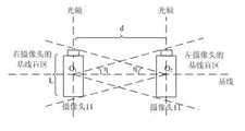
(1)基线盲区检测:从监控中心输出调控信号,转动双目水平角度调节装置的步进电机,使每台摄像头的拍摄视角与基线盲区不重合。所述基线盲区是指基线正负η角度的区域,所述基线为摄像头的水平旋转中心的连线,所述η角度由公式η=tan-1(L/2d)粗略估计,其中d为两台CCD摄像头之间的距离,L为摄像头长度尺寸。(1) Baseline blind spot detection: output control signals from the monitoring center, and turn the stepper motor of the binocular horizontal angle adjustment device so that the shooting angle of each camera does not coincide with the baseline blind spot. The baseline blind area refers to the area of the baseline positive and negative η angles, the baseline is the connection line of the horizontal rotation center of the camera, and the η angle is roughly estimated by the formula η=tan-1 (L/2d), where d is two The distance between the CCD cameras, L is the length of the camera.
(2)寻找火源根部:利用每台摄像头拍摄的火灾图像计算其中的火源根部图像坐标:使用帧差法提取图像中火焰或烟雾的边缘轮廓,取边缘轮廓的底线的坐标中心作为火源根部的图像坐标(x,y)。(2) Find the root of the fire source: use the fire image captured by each camera to calculate the image coordinates of the fire source root: use the frame difference method to extract the edge contour of the flame or smoke in the image, and take the coordinate center of the bottom line of the edge contour as the fire source Image coordinates (x, y) of the root.
(3)主动聚焦:对于每台摄像头,将其中的火源根部图像坐标(x,y)与图像的中心坐标(x0,y0)作比较,计算摄像头的偏移量(Δx,Δy)=(x,y)-(x0,y0)。所述图像的中心坐标(x0,y0)=(M/2,N/2),其中图像的分辨率为M*N,M是图像宽度像素数,N是图像高度像素数。根据摄像头的偏移量发出调控信号,转动双目竖直角度调节装置的步进电机和单目水平角度调节装置的两台步进电机,带动两台摄像头分别转动,然后重复步骤(1)、(2)、(3),直至每台摄像头拍摄到的火灾图像的火源根部图像坐标与图像中心坐标重合,完成聚焦过程。(3) Active focusing: For each camera, compare the image coordinates (x, y) of the root of the fire source with the center coordinates (x0 , y0 ) of the image, and calculate the camera offset (Δx, Δy) = (x, y) - (x0 , y0 ). The center coordinates of the image (x0 , y0 )=(M/2, N/2), wherein the resolution of the image is M*N, M is the number of pixels in the width of the image, and N is the number of pixels in the height of the image. Send a control signal according to the offset of the camera, turn the stepper motor of the binocular vertical angle adjustment device and the two stepper motors of the monocular horizontal angle adjustment device, drive the two cameras to rotate respectively, and then repeat steps (1), (2), (3), until the image coordinates of the root of the fire source of the fire image captured by each camera coincide with the coordinates of the image center, and the focusing process is completed.
(4)获取单目摄像头的偏转角度:主动聚焦完成后,根据两台单目水平角度调节装置的步进电机的初始角度和转动的角度,获取两台摄像头的水平偏转角度α、β。(4) Obtain the deflection angle of the monocular camera: after the active focusing is completed, obtain the horizontal deflection angles α and β of the two cameras according to the initial angle and the rotation angle of the stepping motors of the two monocular horizontal angle adjustment devices.
(5)自适应调整:根据偏转角度α、β,计算两台摄像头之间的夹角ψ=180-α-β,根据ψ的大小发出调控信号,移动单目平动调节装置的两台步进电机,带动两台摄像头移动,从而改变两台摄像头的间距,然后重复步骤(1)、(2)、(3)、(4)、(5),直至夹角满足5.00°<ψ<175.00°。ψ的范围可以根据高精度步进电机的步距角和摄像头的分辨率及经验来调整:步进电机步距角越小,摄像头分辨率越高,可以将ψ范围扩大;反之缩小。(5) Adaptive adjustment: Calculate the included angle ψ=180-α-β between the two cameras according to the deflection angles α and β, send a control signal according to the size of ψ, and move the two steps of the monocular translation adjustment device Enter the motor to drive the two cameras to move, thereby changing the distance between the two cameras, and then repeat steps (1), (2), (3), (4), and (5) until the included angle satisfies 5.00°<ψ<175.00 °. The range of ψ can be adjusted according to the step angle of the high-precision stepping motor and the resolution of the camera and experience: the smaller the step angle of the stepping motor, the higher the resolution of the camera, and the range of ψ can be expanded; otherwise, it can be reduced.
(6)获取双目摄像单元的偏转夹角和摄像头间距:利用红外测距装置测量两台摄像头的间距d;记录双目水平角度调节装置的步进电机和双目竖直角度调节装置的步进电机的初始角度和转动的角度,获取双目水平角度调节装置的步进电机和双目竖直角度调节装置的步进电机的最终偏转角度,进而得到双目摄像单元的水平偏转角度
(7)监控中心计算火源三维坐标:根据以下公式,计算火源三维坐标:(7) The monitoring center calculates the three-dimensional coordinates of the fire source: calculate the three-dimensional coordinates of the fire source according to the following formula:

(8)监控中心根据双目摄像火灾探测与定位装置定位出的火源根部坐标,发出灭火指令。(8) The monitoring center issues a fire extinguishing command according to the coordinates of the root of the fire source located by the binocular camera fire detection and positioning device.
本发明提供了一种集视频火灾探测和图像型火灾定位功能于一体的双目摄像火灾探测与定位装置,以及基于该装置的火灾定位方法。本发明能够准确定位火灾的位置,采用双目摄像头系统模拟人眼系统,从不同角度获取同一时刻的火灾图像,每台摄像头都能将火灾定位在平行于自己的主光轴的轴线上,双目摄像头的光轴之间存在夹角,根据两条直线只能相交于一点,因此能确定火灾的位置。本发明能够便捷的进行火灾定位,采用主动聚焦技术,从软件程序上控制摄像头将火灾聚焦到摄像头的主光轴上,然后利用简单的三角关系就能方便的计算火灾的三维坐标,计算过程中完全不需要摄像头的焦距,偏移焦距等参数,因此也无须进行复杂的摄像头标定工作。这种设计使得本发明装置的安装和操作简单便捷,更加实用。本发明的自适应调整设计使得可以根据不同空间的尺度,通过改变两台摄像头的间距改变两台摄像头间的夹角,使其在任何场所的定位都满足精度要求。The invention provides a binocular camera fire detection and positioning device integrating video fire detection and image fire positioning functions, and a fire positioning method based on the device. The invention can accurately locate the position of the fire, adopts the binocular camera system to simulate the human eye system, and obtains the fire images at the same time from different angles, and each camera can locate the fire on the axis parallel to its own main optical axis. There is an included angle between the optical axes of the camera, and two straight lines can only intersect at one point, so the location of the fire can be determined. The invention can conveniently locate the fire, adopts active focusing technology, controls the camera from the software program to focus the fire on the main optical axis of the camera, and then can conveniently calculate the three-dimensional coordinates of the fire by using a simple triangular relationship, during the calculation process There is no need for camera focal length, offset focal length and other parameters, so there is no need for complicated camera calibration work. This design makes the installation and operation of the device of the present invention simple and convenient, and more practical. The self-adaptive adjustment design of the present invention makes it possible to change the angle between the two cameras by changing the distance between the two cameras according to the scale of different spaces, so that the positioning in any place can meet the precision requirements.
本发明还会带来一定的积极效果:由于双目摄像火灾探测与定位装置的安装操作简单,无须专业的摄像头标定工作,使得普通用户也可以简单方便使用,促进消防设备的普及和应用。此外,由于本发明的自适应设计,双目摄像火灾探测与定位装置能够自动适应于不同空间场所,并且都能满足精度要求,提高了消防设备的精度,促进消防设备的智能化。The present invention also brings certain positive effects: because the installation and operation of the binocular camera fire detection and positioning device is simple and professional camera calibration is not required, ordinary users can also use it simply and conveniently, and promote the popularization and application of fire fighting equipment. In addition, due to the self-adaptive design of the present invention, the binocular camera fire detection and positioning device can automatically adapt to different spaces, and can meet the accuracy requirements, which improves the accuracy of fire-fighting equipment and promotes the intelligence of fire-fighting equipment.
附图说明Description of drawings
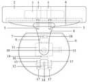
图1本发明双目摄像火灾探测与定位装置的一种实施例示意图正视图。Fig. 1 is a schematic front view of an embodiment of the binocular camera fire detection and positioning device of the present invention.
图2是图1的侧视图。FIG. 2 is a side view of FIG. 1 .
图3包含本发明装置的智能消防系统示意图。Fig. 3 is a schematic diagram of an intelligent fire protection system including the device of the present invention.
图4火源坐标计算示意图。Fig. 4 Schematic diagram of calculation of fire source coordinates.
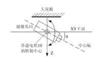
图5双目摄像单元竖直偏转角度θ范围说明图。Fig. 5 Explanatory diagram of the vertical deflection angle θ range of the binocular camera unit.
图6基线盲区示意图。Figure 6 Schematic diagram of the baseline blind zone.
图7火源根部寻找方法图。Figure 7 is a diagram of how to find the root of the fire source.
图8摄像头偏移量示意图。Figure 8 Schematic diagram of camera offset.
图9本发明方法软件流程图。Fig. 9 is a software flowchart of the method of the present invention.
具体实施方式Detailed ways
下面结合附图对本发明作进一步的说明。The present invention will be further described below in conjunction with the accompanying drawings.
实施例Example
参见图1、图2,本实施例装置的具体结构如下:Referring to Fig. 1, Fig. 2, the concrete structure of present embodiment device is as follows:
双目摄像火灾探测与定位装置由双目摄像单元、双目竖直角度调节装置、双目水平角度调节装置组成。The binocular camera fire detection and positioning device is composed of a binocular camera unit, a binocular vertical angle adjustment device, and a binocular horizontal angle adjustment device.
双目摄像单元包括透明防护外壳9,以及设置在透明防护外壳9内的两台CCD摄像头11、单目水平角度调节装置、单目平动调节装置和红外测距装置14。两台CCD摄像头11的参数相同,摄像头分辨率越高定位精度越高;单目水平角度调节装置包括两台参数相同且步距角小于0.01°的高精度步进电机6;单目平动调节装置由两根轨道17、导轨7、两台参数相同的步进电机12和橡胶转动滚轮13构成;红外测距装置14由红外对射器构成。The binocular camera unit includes a transparent
透明防护外壳9为类半球体透明防护罩,透明防护外壳9的壳壁上设置有安装通孔和输出导线的连接孔。透明防护外壳9内的两台CCD摄像头11,安装时镜头同向。两台CCD摄像头11外壳上端分别固定在两台竖向安装的步进电机6下端的转动主轴上,当两台步进电机6转动时,分别带动两台CCD摄像头11在水平面内转动。两台步进电机6机壳的上表面固装有四方形顶座18,顶座18上开有水平方向通孔,导轨7从通孔中穿过,使步进电机6可以沿着导轨7移动。导轨7的两端分别用螺钉固定在透明防护外壳9内上部的侧壁上。在透明防护外壳9内下部的侧壁上分别用螺钉固定两根左右方向的平行轨道17。两台步进电机12横向安装,其两端的转动主轴上分别安装有橡胶转动滚轮13,该滚轮13分别支撑在平行轨道17上,并通过步进电机12带动摄像头11在轨道17上左右平移。固定在透明防护外壳内侧壁上的轨道17和导轨7相互平行。两台横向安装的步进电机12机壳顶部上表面各安装有一个水平转轴套16,在两台CCD摄像头11机壳下表面分别设置有伸出轴19,该伸出轴19与水平转轴套16相配合,使得CCD摄像头11能在水平面内转动。红外测距装置14的发射器和接受器分别安装在两台步进电机12机壳相对的内侧外壁上,能通过红外线对射测量两台CCD摄像头11之间的距离。The transparent
双目竖直角度调节装置包括步距角小于0.01°的高精度步进电机10、转轴15和支撑杆8。右侧的支撑杆8下端与步进电机10机壳固定连接,其步进电机10转动主轴与透明防护外壳9的右侧固定连接。在透明防护外壳9的左侧安装有一转轴15,该转轴15与步进电机10转动主轴同轴线,转轴15的另一端套装在左侧支撑杆8下端的孔中。当高精度步进电机10转动时,带动双目摄像单元在垂直平面内转动。The binocular vertical angle adjustment device includes a high-
双目水平角度调节装置包括步距角小于0.01°的高精度步进电机3和转盘4,高精度步进电机3竖向安装,其下端的转动主轴上安装有转盘4。左右两根支撑杆8的上端用螺钉5固定连接在转盘4上。当高精度步进电机3转动时带动转盘4转动,从而带动双目摄像单元在水平面内转动。圆柱体盖形的安装盘2上开有四个安装螺孔1,通过螺钉连接装置将安装盘2固定在建筑物的顶壁上。高精度步进电机3固装在盖形安装盘2的凹槽内。The binocular horizontal angle adjustment device includes a high-
所述步进电机3、步进电机6、步进电机10、步进电机12、两台摄像头11和红外对射器14分别通过信号传输线路与中转控制器相连接,中转控制器通过信号传输线路与监控中心的计算机相连接。Described
参见图3,本发明装置可以用作智能消防系统的组成部分。智能消防系统一般有前端的图像采集系统,中端的视频图像处理与定位装置控制平台,后端的报警联动灭火系统。本发明的双目摄像火灾探测与定位装置即前端的图像采集系统,该装置模拟人眼双目系统,集视频火灾探测和火灾定位功能于一体,在火灾探测的同时对火灾进行准确定位。监控中心即中端的视频图像处理与定位装置控制平台,本发明的基于双目摄像火灾探测与定位装置的火灾定位方法的实施软件置于监控中心的计算机中,计算机利用本发明装置采集到的视频图像检测到现场有火灾的情况下,对火灾进行定位,为联动灭火提供目标位置。Referring to Fig. 3, the device of the present invention can be used as a component of an intelligent fire protection system. Intelligent fire protection systems generally have a front-end image acquisition system, a mid-end video image processing and positioning device control platform, and a rear-end alarm linkage fire extinguishing system. The binocular camera fire detection and positioning device of the present invention is the front-end image acquisition system. The device simulates the binocular system of human eyes, integrates the functions of video fire detection and fire positioning, and accurately locates the fire while detecting the fire. The monitoring center is the middle-end video image processing and positioning device control platform. The implementation software of the fire positioning method based on the binocular camera fire detection and positioning device of the present invention is placed in the computer of the monitoring center, and the computer uses the video collected by the device of the present invention. When the image detects that there is a fire on the scene, the fire is located and the target position is provided for the linkage fire extinguishing.
参见图4,初始空间坐标系的建立:定义初始安装状态(初始状态时可以使双目摄像单元的中心轴、摄像头的光轴与天花板平行,或者与墙壁的边沿平行)时,两台CCD摄像头11的水平旋转中心即两台步进电机6转动主轴中心的连线为基线,该基线的中垂线为双目摄像单元的中心轴。中心轴、基线、两台CCD摄像头11的光轴均在同一个平面内。以所述基线为X轴,所述中心轴为Y轴,垂直向下的直线为Z轴,建立空间坐标系XYZ,并称其为初始空间。基线和中心轴将随着步进电机3带动双目摄像单元转动而改变角度方位。图4中两台CCD摄像头11的位置是火灾定位后时的状态,初始状态时两台CCD摄像头11位于X轴上。O1和O2是两台CCD摄像头11的水平旋转中心即两台步进电机6的转动主轴中心,其连线O1O2是定位调整后的基线,F为火源位置。O1F是左边CCD摄像头11的光轴、O2F是右边CCD摄像头11的光轴,OD为O1O2的中垂线,且在平面O1O2F内,OD也是双目摄像单元的中心轴。为了方便标识


参见图5,步进电机10的转动主轴转动使双目摄像单元在竖直平面内上下转动,从而改变双目摄像单元的中心轴与XY平面的夹角θ。为了避免CCD摄像头倒转过来拍摄,规定θ的范围-90°<θ<90°。Referring to FIG. 5 , the rotation of the main shaft of the stepping
参见图6,O1、O2分别为两台CCD摄像头11的水平旋转中心即两台步进电机6的轴心,其连线为基线。图中可以看出两台CCD摄像头互相遮挡,存在盲区,盲区位于基线附近一定角度范围内(图中从O1、O2引出的虚线张角内的区域为基线盲区)。定义基线正负η角度的区域为盲区,称之为基线盲区。基线盲区内由于摄像头的遮挡只有一台摄像头能拍摄到火灾图像。若两台CCD摄像头11之间的距离为d,摄像头尺寸为L,η可用公式η=tan-1(L/2d)粗略估计。为了防止两台CCD摄像头11的镜头相对,进入基线盲区,规定α、β角度的范围为η<α、β<360°-η。Referring to FIG. 6 , O1 and O2 are respectively the horizontal rotation centers of the two
参见图8,(x,y)为火源根部的图像坐标,(x0,y0)为图像中心坐标即摄像头的光轴。定义CCD摄像头11的光轴相对于火源根部的图像坐标偏移量称之为摄像头的偏移量。Referring to FIG. 8 , (x, y) are the image coordinates of the root of the fire source, and (x0 , y0 ) are the image center coordinates, that is, the optical axis of the camera. The offset of the image coordinates defining the optical axis of the
参见图9,利用本发明所述装置进行火灾定位方法的具体实现步骤如下:Referring to Fig. 9, the specific implementation steps of the fire location method using the device of the present invention are as follows:
(1)火灾检测:(1) Fire detection:
对于每台摄像头传输来的图像信息,监控中心首先会利用火灾识别算法检测现场是否存在火焰或烟雾,如果不存在,则通过中转控制器控制双目摄像火灾探测与定位装置执行平常的监控工作;检测到存在火灾灾情后,监控中心给出信号控制警灯报警的同时,还通过中转控制器控制双目摄像火灾探测与定位装置进行以下(2)至(9)步骤。For the image information transmitted by each camera, the monitoring center will first use the fire recognition algorithm to detect whether there is flame or smoke on the scene. If there is no flame or smoke, the relay controller will control the binocular camera fire detection and positioning device to perform normal monitoring work; After detecting the existence of a fire disaster, the monitoring center will send a signal to control the alarm lights and at the same time, control the binocular camera fire detection and positioning device through the relay controller to perform the following steps (2) to (9).
(2)基线盲区检测:(2) Baseline blind spot detection:
检测到火灾后,监控中心首先检测火源是否位于基线盲区内。若是,监控中心控制双目水平角度调节装置的步进电机3转动,步进电机3每次转动一个步距角,带动双目摄像单元转动,从而改变双目摄像单元的基线盲区,此过程不断重复,直至基线盲区与火源位置不重合;若否,直接进行步骤(3)。After a fire is detected, the monitoring center first checks whether the fire source is within the baseline blind zone. If so, the monitoring center controls the
(3)寻找火源根部:(3) Find the root of the fire source:
监控中心利用火源根部寻找方法(参见图7)分别计算每台摄像头中的火源根部图像坐标:采集每台摄像头火灾图像,使用简单的帧差法提取各个图像中火焰或烟雾的边缘轮廓的底线,然后取底线的坐标中心作为火源根部的图像坐标(x,y)。The monitoring center uses the method of finding the fire root (see Figure 7) to calculate the image coordinates of the fire root in each camera: collect the fire images of each camera, and use a simple frame difference method to extract the edge profile of the flame or smoke in each image. The bottom line, and then take the coordinate center of the bottom line as the image coordinates (x, y) of the fire root.
(4)主动聚焦调整:(4) Active focus adjustment:
监控中心将每个摄像头的火源根部的图像坐标(x,y)与图像的中心坐标(x0,y0)作比较,计算每台CCD摄像头11的偏移量(Δx,Δy)=(x,y)-(x0,y0)。这里图像的中心坐标(x0,y0)=(M/2,N/2),其中图像的分辨率为M*N,M是图像宽度像素数,N是图像高度像素数。根据偏移量,监控中心控制双目竖直角度调节装置的步进电机10和单目水平角度调节装置的两台步进电机6转动角度,带动两台CCD摄像头11分别转动。当Δx<0时,两台步进电机6分别带动两台CCD摄像头11左转,当Δx>0时,两台步进电机6分别带动两台CCD摄像头11右转;当Δy<0时,步进电机10带动两台CCD摄像头11上转,当Δy>0时,步进电机10带动两台CCD摄像头11下转;此过程中步进电机6和步进电机10每次转动一个步距角,然后返回重复步骤(2)、(3)、(4),直至每台摄像头中的火源根部图像坐标(x,y)与图像中心坐标重合即Δx=0,Δy=0,完成聚焦过程。The monitoring center compares the image coordinates (x, y) of the fire source root of each camera with the center coordinates (x0 , y0 ) of the image, and calculates the offset (Δx, Δy)=(Δx, Δy) of each CCD camera 11 x, y) - (x0 , y0 ). Here, the center coordinates of the image (x0 , y0 )=(M/2, N/2), where the resolution of the image is M*N, where M is the number of pixels in the width of the image, and N is the number of pixels in the height of the image. According to the offset, the monitoring center controls the
(5)获取单目摄像头的偏转角度:(5) Obtain the deflection angle of the monocular camera:
主动聚焦完成后,监控中心根据步进电机6的初始角度和转动的角度,获取步进电机6的偏转角度,即各台CCD摄相头11的偏转角度α、β。After the active focusing is completed, the monitoring center obtains the deflection angle of the
(6)自适应调整:(6) Adaptive adjustment:
监控中心根据偏转角度α、β,计算两台CCD摄像头11之间的夹角ψ=180-α-β。当5.00°<ψ<175.00°时,监控中心控制双目摄像火灾探测与定位装置结束主动聚焦工作;当ψ<5.00°时,监控中心控制单目平动调节装置的两台步进电机12背向移动,增大两台CCD摄像头11之间的距离;当ψ>175.00°时,监控中心控制单目平动调节装置的两台步进电机12相向移动,减小两台CCD摄像头11之间的距离。监控中心控制单目平动调节装置的两台步进电机12移动相等距离,确保两台CCD摄像头11的中心不变。移动一定距离(可以取个固定值如0.5cm)后,必须重新聚焦,重复步骤(2)、(3)、(4)、(5)、(6),直至夹角满足5.00°<ψ<175.00°。这里初步设定5.00°<ψ<175.00°,ψ的范围可以根据高精度步进电机的步距角和摄像头的分辨率及经验来调整:步进电机步距角越小,摄像头分辨率越高,可以将ψ范围扩大;反之缩小。The monitoring center calculates the included angle ψ=180-α-β between the two
(7)获取双目摄像单元的偏转夹角和摄像头间距:(7) Obtain the deflection angle and camera spacing of the binocular camera unit:
监控中心利用红外测距装置14测量两台CCD摄像头11的间距d。监控中心根据步进电机3和步进电机10的初始角度和转动的角度,获取步进电机3最终水平偏转角度和步进电机10的最终竖直偏转角度,即得到双目摄像单元的水平偏转角度
(8)监控中心计算火源三维坐标:(8) The monitoring center calculates the three-dimensional coordinates of the fire source:
当系统主动聚焦、自适应调整后,双目摄像单元相对于初始状态在XY平面内绕Z轴顺时针(逆着Z轴方向看)旋转角度
然后将辅助坐标系X′Y′Z′绕Z′轴逆时针旋转


再将X′Y′Z′空间的坐标变换到XYZ空间的坐标:Then transform the coordinates of the X'Y'Z' space to the coordinates of the XYZ space:

得到初始空间中火源的坐标为:The coordinates of the fire source in the initial space are obtained as:

(9)监控中心根据得到的火源根部坐标,发出指令,控制联动水炮灭火,达到及时遏制火灾的目的。(9) The monitoring center issues instructions based on the obtained coordinates of the root of the fire source to control the linkage water cannon to extinguish the fire, so as to achieve the purpose of timely containing the fire.
实际应用举例:本发明自动化智能化程度高,因此其实施过程方便快捷。1.硬件安装与系统建立:双目摄像火灾探测与定位装置设计的是吊式安装,通过安装盘和安装孔将该装置安装在诸如仓库、商场、剧院等场所的天花板上,然后利用信号传输线与计算机连接,报警装置也与计算机连接。本发明装置同时可与联动灭火系统兼容组成智能消防系统。安装时以该装置中心为原点,建立空间坐标系,为了使灭火系统直接利用定位坐标,可以将水炮与双目摄像火灾探测与定位装置安装于坐标系的轴上。2.装置初始化:系统启动后,对双目摄像火灾探测与定位装置进行简单的初始化,为了省去人工测量初始角度的工作,硬件系统安装时可以保持摄像头与坐标轴平行,利用监控中心将获取的各角度α0、β0、θ0、


Claims (5)
Translated fromChinese

Priority Applications (1)
| Application Number | Priority Date | Filing Date | Title |
|---|---|---|---|
| CN 201110238242CN102298818B (en) | 2011-08-18 | 2011-08-18 | Binocular shooting fire detecting and positioning device and fire positioning method thereof |
Applications Claiming Priority (1)
| Application Number | Priority Date | Filing Date | Title |
|---|---|---|---|
| CN 201110238242CN102298818B (en) | 2011-08-18 | 2011-08-18 | Binocular shooting fire detecting and positioning device and fire positioning method thereof |
Publications (2)
| Publication Number | Publication Date |
|---|---|
| CN102298818Atrue CN102298818A (en) | 2011-12-28 |
| CN102298818B CN102298818B (en) | 2013-07-10 |
Family
ID=45359209
Family Applications (1)
| Application Number | Title | Priority Date | Filing Date |
|---|---|---|---|
| CN 201110238242Expired - Fee RelatedCN102298818B (en) | 2011-08-18 | 2011-08-18 | Binocular shooting fire detecting and positioning device and fire positioning method thereof |
Country Status (1)
| Country | Link |
|---|---|
| CN (1) | CN102298818B (en) |
Cited By (24)
| Publication number | Priority date | Publication date | Assignee | Title |
|---|---|---|---|---|
| CN104092923A (en)* | 2014-07-21 | 2014-10-08 | 国家电网公司 | Intelligent Video Ranging Method for Transmission Lines |
| CN104092922A (en)* | 2014-07-21 | 2014-10-08 | 国家电网公司 | Smart video distance control method for live bodies in substations |
| CN104436501A (en)* | 2014-12-15 | 2015-03-25 | 中国科学技术大学 | Fire extinguishing control method, device and system based on fire monitor technology |
| CN104853067A (en)* | 2014-12-12 | 2015-08-19 | 讯美电子科技有限公司 | Camera with transparent housing |
| CN105205969A (en)* | 2015-09-23 | 2015-12-30 | 陈一平 | Intelligent positioning device for three-dimensional space fire source detection |
| CN106506927A (en)* | 2016-12-09 | 2017-03-15 | 努比亚技术有限公司 | A kind of terminal and the method shot using terminal |
| CN107025428A (en)* | 2015-11-25 | 2017-08-08 | A.M.总建筑股份公司 | The infra-red radiation fire detector with complex function for the confined space |
| CN107516398A (en)* | 2017-08-09 | 2017-12-26 | 湖北泰龙互联通信股份有限公司 | A kind of technology of flame detecting and video image linkage |
| CN108805880A (en)* | 2018-05-28 | 2018-11-13 | 佘以道 | A kind of safety protecting method |
| CN109725340A (en)* | 2018-12-31 | 2019-05-07 | 成都纵横大鹏无人机科技有限公司 | Direct geographic positioning and device |
| CN109859436A (en)* | 2019-02-26 | 2019-06-07 | 浙江晶鲸科技有限公司 | Fire-disaster monitoring device and fire monitoring system with positioning function |
| CN109887025A (en)* | 2019-01-31 | 2019-06-14 | 沈阳理工大学 | Monocular self-adjusting fire point three-dimensional positioning method and device |
| CN109903507A (en)* | 2019-03-04 | 2019-06-18 | 上海海事大学 | A fire intelligent monitoring system and method based on deep learning |
| CN110057301A (en)* | 2019-04-29 | 2019-07-26 | 慧眼自动化科技(广州)有限公司 | A kind of height detecting device and detection method based on binocular 3D parallax |
| CN110849328A (en)* | 2019-11-26 | 2020-02-28 | 安徽德睿智能技术有限公司 | Crystalline silicon measuring device based on binocular vision |
| CN111444763A (en)* | 2020-02-24 | 2020-07-24 | 珠海格力电器股份有限公司 | Security control method and device, storage medium and air conditioner |
| US10728514B2 (en) | 2014-12-04 | 2020-07-28 | SZ DJI Technology Co., Ltd. | Imaging system and method |
| CN111754574A (en)* | 2020-05-28 | 2020-10-09 | 北京中科慧眼科技有限公司 | Distance testing method, device, system and storage medium based on binocular camera |
| CN111953933A (en)* | 2020-07-03 | 2020-11-17 | 北京中安安博文化科技有限公司 | Method, device, medium and electronic equipment for determining fire area |
| CN112634578A (en)* | 2020-12-17 | 2021-04-09 | 招商局重庆交通科研设计院有限公司 | Variable escape indicating system for tunnel |
| CN113053057A (en)* | 2019-12-26 | 2021-06-29 | 杭州海康微影传感科技有限公司 | Fire point positioning system and method |
| CN113413564A (en)* | 2021-05-28 | 2021-09-21 | 浙江工业大学 | Fire source positioning and fire extinguishing control method for fire-fighting robot |
| CN114267145A (en)* | 2021-12-22 | 2022-04-01 | 江苏智库智能科技有限公司 | Warehouse area intrusion detection alarm method and system |
| WO2022217671A1 (en)* | 2021-04-14 | 2022-10-20 | 中国矿业大学 | Fire monitor system having variable-viewing-angle binocular structure, and method |
Families Citing this family (1)
| Publication number | Priority date | Publication date | Assignee | Title |
|---|---|---|---|---|
| CN106851095B (en)* | 2017-01-13 | 2019-12-24 | 深圳拓邦股份有限公司 | Positioning method, device and system |
Citations (3)
| Publication number | Priority date | Publication date | Assignee | Title |
|---|---|---|---|---|
| WO2009087974A1 (en)* | 2008-01-11 | 2009-07-16 | Panasonic Corporation | Binocular camera module |
| CN101574567A (en)* | 2009-06-08 | 2009-11-11 | 南京航空航天大学 | Computer vision technique based method and system for detecting and extinguishing fire disaster intelligently |
| CN102034092A (en)* | 2010-12-03 | 2011-04-27 | 北京航空航天大学 | Active compound binocular rapid target searching and capturing system based on independent multiple-degree-of-freedom vision modules |
- 2011
- 2011-08-18CNCN 201110238242patent/CN102298818B/ennot_activeExpired - Fee Related
Patent Citations (3)
| Publication number | Priority date | Publication date | Assignee | Title |
|---|---|---|---|---|
| WO2009087974A1 (en)* | 2008-01-11 | 2009-07-16 | Panasonic Corporation | Binocular camera module |
| CN101574567A (en)* | 2009-06-08 | 2009-11-11 | 南京航空航天大学 | Computer vision technique based method and system for detecting and extinguishing fire disaster intelligently |
| CN102034092A (en)* | 2010-12-03 | 2011-04-27 | 北京航空航天大学 | Active compound binocular rapid target searching and capturing system based on independent multiple-degree-of-freedom vision modules |
Cited By (31)
| Publication number | Priority date | Publication date | Assignee | Title |
|---|---|---|---|---|
| CN104092923A (en)* | 2014-07-21 | 2014-10-08 | 国家电网公司 | Intelligent Video Ranging Method for Transmission Lines |
| CN104092922A (en)* | 2014-07-21 | 2014-10-08 | 国家电网公司 | Smart video distance control method for live bodies in substations |
| US10728514B2 (en) | 2014-12-04 | 2020-07-28 | SZ DJI Technology Co., Ltd. | Imaging system and method |
| CN104853067A (en)* | 2014-12-12 | 2015-08-19 | 讯美电子科技有限公司 | Camera with transparent housing |
| CN104436501A (en)* | 2014-12-15 | 2015-03-25 | 中国科学技术大学 | Fire extinguishing control method, device and system based on fire monitor technology |
| CN104436501B (en)* | 2014-12-15 | 2017-11-28 | 中国科学技术大学 | A kind of control extinguishing method, apparatus and system based on fire monitor technology |
| CN105205969A (en)* | 2015-09-23 | 2015-12-30 | 陈一平 | Intelligent positioning device for three-dimensional space fire source detection |
| CN107025428A (en)* | 2015-11-25 | 2017-08-08 | A.M.总建筑股份公司 | The infra-red radiation fire detector with complex function for the confined space |
| CN107025428B (en)* | 2015-11-25 | 2022-01-25 | A.M.总建筑股份公司 | Infrared radiation fire detector with composite function for limited space |
| CN106506927A (en)* | 2016-12-09 | 2017-03-15 | 努比亚技术有限公司 | A kind of terminal and the method shot using terminal |
| CN107516398A (en)* | 2017-08-09 | 2017-12-26 | 湖北泰龙互联通信股份有限公司 | A kind of technology of flame detecting and video image linkage |
| CN108805880B (en)* | 2018-05-28 | 2019-04-30 | 广东阳光世纪智能家居科技有限公司 | A kind of safety protective dining table based on gradient analysis |
| CN108805880A (en)* | 2018-05-28 | 2018-11-13 | 佘以道 | A kind of safety protecting method |
| CN109725340A (en)* | 2018-12-31 | 2019-05-07 | 成都纵横大鹏无人机科技有限公司 | Direct geographic positioning and device |
| CN109887025A (en)* | 2019-01-31 | 2019-06-14 | 沈阳理工大学 | Monocular self-adjusting fire point three-dimensional positioning method and device |
| CN109859436A (en)* | 2019-02-26 | 2019-06-07 | 浙江晶鲸科技有限公司 | Fire-disaster monitoring device and fire monitoring system with positioning function |
| CN109859436B (en)* | 2019-02-26 | 2020-07-14 | 浙江晶鲸科技有限公司 | Fire monitoring device and fire monitoring system with positioning function |
| CN109903507A (en)* | 2019-03-04 | 2019-06-18 | 上海海事大学 | A fire intelligent monitoring system and method based on deep learning |
| CN110057301A (en)* | 2019-04-29 | 2019-07-26 | 慧眼自动化科技(广州)有限公司 | A kind of height detecting device and detection method based on binocular 3D parallax |
| CN110849328A (en)* | 2019-11-26 | 2020-02-28 | 安徽德睿智能技术有限公司 | Crystalline silicon measuring device based on binocular vision |
| CN110849328B (en)* | 2019-11-26 | 2022-03-18 | 安徽德睿智能技术有限公司 | Crystalline silicon measuring device based on binocular vision |
| CN113053057A (en)* | 2019-12-26 | 2021-06-29 | 杭州海康微影传感科技有限公司 | Fire point positioning system and method |
| CN111444763A (en)* | 2020-02-24 | 2020-07-24 | 珠海格力电器股份有限公司 | Security control method and device, storage medium and air conditioner |
| CN111754574A (en)* | 2020-05-28 | 2020-10-09 | 北京中科慧眼科技有限公司 | Distance testing method, device, system and storage medium based on binocular camera |
| CN111953933B (en)* | 2020-07-03 | 2022-07-05 | 北京中安安博文化科技有限公司 | Method, device, medium and electronic equipment for determining fire area |
| CN111953933A (en)* | 2020-07-03 | 2020-11-17 | 北京中安安博文化科技有限公司 | Method, device, medium and electronic equipment for determining fire area |
| CN112634578A (en)* | 2020-12-17 | 2021-04-09 | 招商局重庆交通科研设计院有限公司 | Variable escape indicating system for tunnel |
| WO2022217671A1 (en)* | 2021-04-14 | 2022-10-20 | 中国矿业大学 | Fire monitor system having variable-viewing-angle binocular structure, and method |
| CN113413564A (en)* | 2021-05-28 | 2021-09-21 | 浙江工业大学 | Fire source positioning and fire extinguishing control method for fire-fighting robot |
| CN114267145A (en)* | 2021-12-22 | 2022-04-01 | 江苏智库智能科技有限公司 | Warehouse area intrusion detection alarm method and system |
| CN114267145B (en)* | 2021-12-22 | 2023-12-22 | 江苏智库智能科技有限公司 | Warehouse area intrusion detection alarm method and system |
Also Published As
| Publication number | Publication date |
|---|---|
| CN102298818B (en) | 2013-07-10 |
Similar Documents
| Publication | Publication Date | Title |
|---|---|---|
| CN102298818B (en) | Binocular shooting fire detecting and positioning device and fire positioning method thereof | |
| KR102805693B1 (en) | System and Method of Capturing and Generating Panoramic Three-Dimensional Images | |
| CN103278139B (en) | A kind of varifocal single binocular vision sensing device | |
| CN104079868B (en) | The laser assisted range unit and method of a kind of single-view video monitoring | |
| CN113289290B (en) | Fire-fighting robot flame automatic aiming method, device and system | |
| CN102840825B (en) | Particle locating system and method | |
| CN112329531B (en) | Linear array binocular imaging system for pipe gallery apparent disease detection and working method | |
| CN106042005B (en) | The method of work of bionic eye location tracking system | |
| CN112819943B (en) | Active vision SLAM system based on panoramic camera | |
| US10849589B2 (en) | X-ray imaging apparatus and control method thereof | |
| CN103285548B (en) | Method and device for positioning ground fire by monocular camera | |
| CN105676884B (en) | A kind of device and method that infrared thermal imaging search and track aims at | |
| CN106127115B (en) | A hybrid vision target localization method based on panoramic and conventional vision | |
| CN102636152B (en) | Active visual ranging system of movable platform | |
| CN105031868A (en) | Self-adaption fire extinguishing method based on fire scale | |
| CN111182210A (en) | A dual-pan-tilt multi-target tracking camera for binocular analysis | |
| CN114245091A (en) | Projection position correction method, projection positioning method, control device and robot | |
| CN117745827A (en) | Method and system for jointly positioning fire source and high-temperature point in space based on infrared camera and binocular camera and fire water monitor | |
| CN113041537A (en) | Fire monitor system with variable-visual-angle binocular structure and method | |
| CN119941848A (en) | Fire source identification and positioning system of firefighting robot based on binocular vision and thermal imaging | |
| CN103884272A (en) | Method and device for determination of object position, and mobile electronic device | |
| CN202582535U (en) | Active visual ranging system of movable platform | |
| CN112884845A (en) | Indoor robot obstacle positioning method based on single camera | |
| CN115337581B (en) | Fire-fighting method based on multi-view vision fire-fighting system | |
| CN205384519U (en) | Device that aims is trailed in infrared thermal imaging search |
Legal Events
| Date | Code | Title | Description |
|---|---|---|---|
| C06 | Publication | ||
| PB01 | Publication | ||
| C10 | Entry into substantive examination | ||
| SE01 | Entry into force of request for substantive examination | ||
| C14 | Grant of patent or utility model | ||
| GR01 | Patent grant | ||
| CF01 | Termination of patent right due to non-payment of annual fee | Granted publication date:20130710 Termination date:20160818 | |
| CF01 | Termination of patent right due to non-payment of annual fee |