CN102289316A - Method and apparatus for correcting touch coordinates in touch system - Google Patents
Method and apparatus for correcting touch coordinates in touch systemDownload PDFInfo
- Publication number
- CN102289316A CN102289316ACN2011101609634ACN201110160963ACN102289316ACN 102289316 ACN102289316 ACN 102289316ACN 2011101609634 ACN2011101609634 ACN 2011101609634ACN 201110160963 ACN201110160963 ACN 201110160963ACN 102289316 ACN102289316 ACN 102289316A
- Authority
- CN
- China
- Prior art keywords
- touch
- conductor
- size
- lookup table
- values
- Prior art date
- Legal status (The legal status is an assumption and is not a legal conclusion. Google has not performed a legal analysis and makes no representation as to the accuracy of the status listed.)
- Pending
Links
Images


Classifications
- G—PHYSICS
- G06—COMPUTING OR CALCULATING; COUNTING
- G06F—ELECTRIC DIGITAL DATA PROCESSING
- G06F3/00—Input arrangements for transferring data to be processed into a form capable of being handled by the computer; Output arrangements for transferring data from processing unit to output unit, e.g. interface arrangements
- G06F3/01—Input arrangements or combined input and output arrangements for interaction between user and computer
- G06F3/03—Arrangements for converting the position or the displacement of a member into a coded form
- G06F3/041—Digitisers, e.g. for touch screens or touch pads, characterised by the transducing means
- G06F3/0416—Control or interface arrangements specially adapted for digitisers
- G06F3/0418—Control or interface arrangements specially adapted for digitisers for error correction or compensation, e.g. based on parallax, calibration or alignment
- G—PHYSICS
- G06—COMPUTING OR CALCULATING; COUNTING
- G06F—ELECTRIC DIGITAL DATA PROCESSING
- G06F3/00—Input arrangements for transferring data to be processed into a form capable of being handled by the computer; Output arrangements for transferring data from processing unit to output unit, e.g. interface arrangements
- G06F3/01—Input arrangements or combined input and output arrangements for interaction between user and computer
- G06F3/03—Arrangements for converting the position or the displacement of a member into a coded form
- G06F3/041—Digitisers, e.g. for touch screens or touch pads, characterised by the transducing means
- G06F3/044—Digitisers, e.g. for touch screens or touch pads, characterised by the transducing means by capacitive means
- G06F3/0446—Digitisers, e.g. for touch screens or touch pads, characterised by the transducing means by capacitive means using a grid-like structure of electrodes in at least two directions, e.g. using row and column electrodes
Landscapes
- Engineering & Computer Science (AREA)
- General Engineering & Computer Science (AREA)
- Theoretical Computer Science (AREA)
- Human Computer Interaction (AREA)
- Physics & Mathematics (AREA)
- General Physics & Mathematics (AREA)
- Position Input By Displaying (AREA)
Abstract
Translated fromChineseDescription
Translated fromChinese相关申请的交叉引用Cross References to Related Applications
本申请要求于2010年6月18日提交的韩国专利申请No.10-2010-0058225的优先权,通过引用的方式将其整体内容合并于此。This application claims priority from Korean Patent Application No. 10-2010-0058225 filed on June 18, 2010, the entire contents of which are hereby incorporated by reference.
技术领域technical field
本发明构思的实施例一般涉及用于电子设备的显示系统。更具体地,本发明构思的实施例涉及包括诸如触摸面板之类的触摸接口的显示系统。Embodiments of the inventive concept generally relate to display systems for electronic devices. More particularly, embodiments of the inventive concept relate to a display system including a touch interface such as a touch panel.
背景技术Background technique
特定电子设备包括具有触摸接口的显示器。这种显示器通常称为触摸屏。触摸接口允许用户将诸如手指或手写笔之类的输入物体接近触摸屏放置来通过触摸屏与电子设备进行交互。略举数例,具有采用的触摸屏的设备的示例包括智能电话、自动柜员机(ATM)、电视(TV)和家用电器。Certain electronic devices include displays with touch interfaces. Such displays are often referred to as touch screens. A touch interface allows a user to interact with the electronic device through the touch screen by placing an input object, such as a finger or a stylus, in close proximity to the touch screen. Examples of devices with touch screens employed include smartphones, automated teller machines (ATMs), televisions (TVs), and home appliances, to name a few.
在触摸接口中,诸如像素坐标之类的显示坐标一般与触摸坐标有关。换句话说,当用户触摸显示器的一部分时,触摸接口生成相应于显示器被触摸的位置的触摸坐标。在显示坐标和触摸坐标之间的精确对应允许触摸接口基于用户输入精确地控制电子设备。In touch interfaces, display coordinates, such as pixel coordinates, are generally related to touch coordinates. In other words, when a user touches a portion of the display, the touch interface generates touch coordinates corresponding to where the display was touched. The precise correspondence between display coordinates and touch coordinates allows the touch interface to precisely control the electronic device based on user input.
可以使用各种技术中的一个来形成显示器,诸如液晶显示器(LCD)设备、场致发射显示器(FED)设备、有机发光显示器(OLED)设备或等离子显示面板(PDP)设备。The display may be formed using one of various technologies, such as a liquid crystal display (LCD) device, a field emission display (FED) device, an organic light emitting display (OLED) device, or a plasma display panel (PDP) device.
可以使用各种技术形成触摸屏,诸如阻性感测技术、电容性感测技术、表面声波感测技术、红外传感技术、表面弹性波感测技术和感性感测技术。Touch screens may be formed using various technologies, such as resistive sensing technology, capacitive sensing technology, surface acoustic wave sensing technology, infrared sensing technology, surface elastic wave sensing technology, and inductive sensing technology.
在使用阻性覆盖感测技术的触摸屏中,阻性材料被涂敷在玻璃或透明塑料板上,聚酯薄膜覆盖在其上,并且每隔一定间隔安装绝缘条使得聚酯薄膜的两面彼此不接触。随后,当用户将手指或其他输入物体接近触摸屏放置时,导致阻性材料的电阻或电压发生改变。可以根据电阻或电压的改变感测输入物体的位置。使用阻性覆盖感测技术的触摸屏一般可以接收草写体输入,但是它们可能遭受低透光度和低耐用性并且不能执行多点感测。In a touch screen that uses resistive overlay sensing technology, a resistive material is coated on a glass or clear plastic plate, mylar is overlaid, and insulating strips are installed at regular intervals so that the two sides of the mylar are not separated from each other. touch. Subsequently, when a user places a finger or other input object in close proximity to the touchscreen, it causes the resistance or voltage of the resistive material to change. The position of an input object can be sensed based on a change in resistance or voltage. Touch screens using resistive overlay sensing technology can generally receive cursive input, but they can suffer from low light transmission and durability and cannot perform multi-point sensing.
在使用表面声波感测技术的触摸屏中,用于发射声波的发射器和用于反射声波的反射器每隔一定间隔地附装到表面玻璃,并且接收器附装到与发射器和反射器所附装的玻璃侧相反的表面。在诸如手指的输入物体中断声波的处理路径的时刻被用来识别触摸点。In a touch screen using surface acoustic wave sensing technology, emitters for emitting sound waves and reflectors for reflecting sound waves are attached to the surface glass at regular intervals, and receivers are attached to the same surface as the emitters and reflectors. Attached to the opposite surface of the glass side. The moment at which an input object, such as a finger, interrupts the processing path of the sound waves is used to identify a touch point.
在使用红外传感技术的触摸屏中,使用红外线的线性度检测输入物体的位置。通过将作为发光设备的红外发光二极管(LED)和作为光接收设备的光敏晶体管两者相对布置来形成矩阵。由诸如手指的输入物体造成的光的拦截允许矩阵检测触摸点的位置。In a touch screen using infrared sensing technology, the linearity of infrared rays is used to detect the position of an input object. A matrix is formed by opposingly arranging infrared light emitting diodes (LEDs) as light emitting devices and phototransistors as light receiving devices. Interception of light by an input object such as a finger allows the matrix to detect the location of the touch point.
研究人员继续致力于研究以上及其他技术以力图改善触摸屏设备的性能及其他能力。Researchers continue to work on these and other techniques in an attempt to improve the performance and other capabilities of touchscreen devices.
发明内容Contents of the invention
根据本发明构思的一个实施例,提供一种操作触摸系统的方法,所述方法包括:存储用于校正触摸面板的触摸坐标值的查找表;获得响应于触摸面板上的触摸导体而生成的触摸数据并从获得的触摸数据计算触摸坐标值;测量触摸导体的尺寸;以及通过使用触摸坐标值和触摸导体的尺寸作为输入参数访问查找表来校正触摸坐标值。According to one embodiment of the inventive concept, there is provided a method of operating a touch system, the method comprising: storing a lookup table for correcting touch coordinate values of a touch panel; obtaining touch coordinates generated in response to touch conductors on the touch panel and calculating touch coordinate values from the obtained touch data; measuring the size of the touch conductor; and correcting the touch coordinate value by accessing a lookup table using the touch coordinate value and the size of the touch conductor as input parameters.
根据本发明构思的另一实施例,提供一种触摸传感系统,所述系统包括:查找表存储单元,存储用于校正触摸面板的触摸坐标值的查找表;触摸数据获得单元,响应于触摸面板上的触摸获得触摸数据;处理器,从获得的触摸数据计算触摸坐标值,并测量触摸导体的尺寸;以及触摸坐标值校正单元,通过使用触摸坐标值和导体的尺寸作为输入参数访问查找表来校正触摸坐标值。According to another embodiment of the inventive concept, there is provided a touch sensing system, the system comprising: a lookup table storage unit storing a lookup table for correcting a touch coordinate value of a touch panel; a touch data obtaining unit responding to a touch The touch on the panel obtains touch data; the processor calculates a touch coordinate value from the obtained touch data, and measures a size of the touch conductor; and a touch coordinate value correction unit accesses a lookup table by using the touch coordinate value and the size of the conductor as input parameters To correct the touch coordinate value.
根据本发明构思的另一实施例,触摸接口包括将导体尺寸和触摸输入的二维坐标映射到二维像素坐标上的三维查找表。According to another embodiment of the inventive concept, the touch interface includes a three-dimensional lookup table that maps conductor sizes and two-dimensional coordinates of a touch input to two-dimensional pixel coordinates.
本发明构思的这些及其他实施例可以改善在触摸感测系统中的触摸坐标值和像素值之间的对应,并且可以有助于提高触摸传感系统中的性能。These and other embodiments of inventive concepts may improve the correspondence between touch coordinate values and pixel values in a touch sensing system, and may contribute to improved performance in the touch sensing system.
附图说明Description of drawings
附图示出本发明构思的选择实施例。在附图中,相似的参考标号指示相似的特征。The drawings illustrate selected embodiments of the inventive concept. In the drawings, like reference numbers indicate like features.
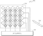
图1示出使用交互容性感测技术的触摸面板。Figure 1 shows a touch panel using interactive capacitive sensing technology.
图2示出用于处理触摸信号的触摸面板和信号处理单元。FIG. 2 illustrates a touch panel and a signal processing unit for processing touch signals.
图3A和图3B示出根据触摸面板中的导体的不同尺寸,触摸元件(cell)中的变化。3A and 3B illustrate changes in touch cells according to different sizes of conductors in the touch panel.
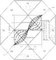
图4A到图4C示出根据触摸面板中导体的不同尺寸的、在真实坐标值和由系统获得的坐标值之间的差值。4A to 4C illustrate differences between real coordinate values and coordinate values obtained by the system according to different sizes of conductors in the touch panel.
图5是示出在根据本发明构思的实施例的触摸面板中,根据导体的不同尺寸校正触摸坐标值的方法的流程图。FIG. 5 is a flowchart illustrating a method of correcting touch coordinate values according to different sizes of conductors in a touch panel according to an embodiment of the inventive concept.
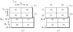
图6示出根据本发明构思实施例的用于触摸面板的像素的两个3D直接查找表。FIG. 6 illustrates two 3D direct lookup tables for pixels of a touch panel according to an embodiment of the inventive concept.
图7示出根据本发明构思实施例的、用于将3D内插法应用于触摸面板的像素的查找表。FIG. 7 illustrates a lookup table for applying a 3D interpolation method to pixels of a touch panel, according to an embodiment of the inventive concept.
图8是根据本发明构思的实施例的触摸坐标校正控制器的框图。FIG. 8 is a block diagram of a touch coordinate correction controller according to an embodiment of the inventive concept.
图9是根据本发明构思实施例的执行触摸坐标校正功能的触摸系统的框图。FIG. 9 is a block diagram of a touch system performing a touch coordinate correction function according to an embodiment of the inventive concept.
图10是根据本发明构思实施例的、包括触摸坐标校正控制器的触摸系统的框图。FIG. 10 is a block diagram of a touch system including a touch coordinate correction controller, according to an embodiment of the inventive concept.
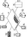
图11示出可以合并根据本发明构思实施例的触摸系统的各个系统。FIG. 11 illustrates various systems that may incorporate a touch system according to an embodiment of the inventive concept.
具体实施方式Detailed ways
将参照附图如下描述本发明构思的实施例。给出这些实施例作为教导示例并且不应该被解释为限制本发明构思的范围。Embodiments of the inventive concept will be described as follows with reference to the accompanying drawings. These examples are given as teaching examples and should not be construed as limiting the scope of the inventive concept.
在下面的描述中,在部件被称作“形成在”另一部件“之上”的情况,它可以直接地形成在另一部件之上,或者可以存在其他中间部件。相反地,在部件被称作“直接形成在”另一部件“之上”的情况,则不存在中间部件或中间层。可以以类似方式解释其他用于表述元件或层之间的关系的词(例如,“在......之间”对“直接在......之间”、“相邻”对“直接相邻”等等)。In the following description, where a component is referred to as being “formed on” another component, it may be directly formed on another component, or other intervening components may be present. In contrast, where an element is referred to as being "formed directly on" another element, there are no intervening elements or layers present. Other words used to describe the relationship between elements or layers may be interpreted in a similar fashion (e.g., "between" versus "directly between", "adjacent" for "immediately adjacent", etc.).
虽然术语第一、第二、第三等在此用作描述不同的部件,但是这些部件不限于这些术语。相反地,这些术语仅用于将一个部件与另一个区别开。因此,第一部件可以替换地称为第二部件而不脱离本发明构思的范围。Although the terms first, second, third, etc. are used herein to describe various components, the components are not limited to these terms. Rather, these terms are only used to distinguish one component from another. Therefore, the first component may be alternatively called the second component without departing from the scope of the present inventive concept.
此处使用的术语仅用于描述具体的实施例而不是试图限制本发明构思。如此处所用,单数形式“一”、“一个”和“该”同样试图包括复数形式,除非上下文另外明确指出。当在本描述中使用术语“包含”和/或“包括”时,确定了所述的部件的存在,但是没有排除其他部件的存在。The terms used herein are for describing specific embodiments only and are not intended to limit the inventive concepts. As used herein, the singular forms "a", "an" and "the" are intended to include the plural forms as well, unless the context clearly dictates otherwise. When the terms "comprising" and/or "comprising" are used in the present description, the presence of stated components is determined, but the presence of other components is not excluded.
除非另外定义,所有在此使用的术语(包括技术和科技术语)具有相同的含义,该含义通常能够被本技术领域的普通技术人员理解。诸如那些定义在通用词典中的术语应该解释为具有在相关技术领域的上下文中的含义相一致的含义,而不应该以理想化或过度正式的感觉解释,除非此处明确定义。Unless otherwise defined, all terms (including technical and scientific terms) used herein have the same meaning as commonly understood by one of ordinary skill in the art. Terms such as those defined in commonly used dictionaries should be interpreted as having meanings consistent with their meanings in the context of the relevant technical field, and should not be interpreted in an idealized or overly formal sense unless explicitly defined herein.
特定实施例涉及容性触摸传感系统(CTSS),该系统响应于诸如手指或导电棒之类的输入物体的存在来检测触摸面板中布置的电极的电容值中的变化。基于检测的变化,CTSS从触摸面板提取数据以指示输入物体使触摸面板运行(actuate)之处的坐标。典型地,触摸面板使用自电容方法或互电容方法进行操作。Certain embodiments relate to capacitive touch sensing systems (CTSS) that detect changes in the capacitance value of electrodes disposed in a touch panel in response to the presence of an input object, such as a finger or a conductive rod. Based on the detected changes, the CTSS extracts data from the touch panel to indicate the coordinates where the input object actuates the touch panel. Typically, touch panels operate using a self-capacitance method or a mutual-capacitance method.
图1示出使用交互容性感测技术的触摸面板。Figure 1 shows a touch panel using interactive capacitive sensing technology.
参照图1,将预定的电压脉冲施加于驱动电极并且在接收电极中聚集与该电压脉冲相应的电荷。在手指放置在驱动电极和接收电极之间的情况中,由点线标记的场耦合发生改变。Referring to FIG. 1, a predetermined voltage pulse is applied to a driving electrode and charges corresponding to the voltage pulse are accumulated in a receiving electrode. In the case where a finger is placed between the drive and receive electrodes, the field coupling, marked by the dotted line, changes.
使用这种触摸面板的系统感测在两个电极之间的场耦合方面的改变、确定触摸点并且在显示装置上显示触摸点。A system using such a touch panel senses a change in field coupling between two electrodes, determines a touch point, and displays the touch point on a display device.
图2示出用于处理触摸信号的触摸面板210和信号处理单元220。FIG. 2 illustrates a
参照图2,触摸系统200包括:触摸面板210,包括多个感测单元;以及信号处理单元220,响应于在导体250和触摸面板210之间的触摸来感测在触摸面板210的每个感测单元的电容中的改变。信号处理单元220还处理所述改变以生成触摸数据。2, the
触摸面板210包括以行方向排列的多个感测单元和以列方向排列的多个感测单元。如图2所示,触摸面板210包括多个行,并且在每个行中布置多个感测单元。布置在每个行中的感测单元彼此电连接,从而一行形式一个电极。触摸面板210还包括多个列,并且在每个列中布置多个感测单元。布置在每个列中的感测单元彼此电连接。The
当导体250触摸触摸面板210时信号处理单元220感测在触摸面板210的每个感测单元的电容中的改变并且生成触摸数据。通过感测在多个行中的以及在多个列中的每个传感器的电容中的改变,信号处理单元220可以确定导体250是否触摸触摸面板210并且确定触摸点。The
在导体250触摸触摸面板210的情况中,触摸面板210的实际触摸点和由信号处理单元220提取的触摸坐标可能不精确地彼此对应。例如,由于触摸面板210的像素的形状和密度、噪声环境和导体250的尺寸,实际触摸点和由触摸系统200计算的坐标可能彼此不同。In case the
CTSS一般使用加权平均法来提取触摸坐标。以下等式(1)表示这种加权平均法的示例。CTSS generally uses a weighted average method to extract touch coordinates. Equation (1) below represents an example of such a weighted average method.
等式(1)Equation (1)
在等式(1)中,表示电极的物理坐标,c表示由电极感测的触摸信号,并且N表示触摸电极或沟道(channel)的数量。根据c的相对比大体上确定坐标X和Y。例如,假设导体250触摸触摸面板210,并且相应于实际坐标p={10,20,30,40,50},信号处理单元220在=对于被认为是x轴上的显著(significant)触摸坐标的触摸坐标5、15和7,N=3,并且根据等式(1)x轴上的触摸坐标x=20x(5/27)+30x(15/27)+40x(7/27)=30.74。也就是说,最大触摸坐标值在物理坐标30附近,并且在x轴上物理坐标30的两侧的物理坐标20和物理坐标40具有几乎同样的坐标值5和7,从而结果值相应于在x轴上的坐标值大约是30的预测。In Equation (1), c denotes physical coordinates of the electrodes, c denotes touch signals sensed by the electrodes, and N denotes the number of touch electrodes or channels. The coordinates X and Y are generally determined from the relative ratio of c. For example, assuming that the
为了根据电极的形状和对齐方式(alignment)精确地校正根据等式(1)提取的坐标,感测方法可以考虑在导体250的触摸的尺寸方面的变化,如将要参考图3A和图3B所描述的那样。In order to accurately correct the coordinates extracted according to equation (1) according to the shape and alignment of the electrodes, the sensing method may account for variations in the size of the touch of the
图3A和图3B示出根据触摸面板中的导体的不同尺寸的、触摸元件中的变化。在图3A和图3B中,电极X1和电极X2在X轴和Y轴具有菱形形状。3A and 3B illustrate changes in touch elements according to different sizes of conductors in a touch panel. In FIGS. 3A and 3B , the electrodes X1 and X2 have rhombus shapes in the X-axis and Y-axis.
参照图3A,导电柱310与电极X1和电极X2的中心像素重叠之处的面积大于在导电柱310与电极X1和电极X2之间的重叠的其他面积。因此,通过中心像素获得的触摸数据值是最大的。导电柱310与电极X1的上部和下部重叠之处的面积第二大。Referring to FIG. 3A , an area where the conductive pillar 310 overlaps the central pixel of the electrodes X1 and X2 is larger than other areas where the conductive pillar 310 overlaps the electrodes X1 and X2 . Therefore, the touch data value obtained by the center pixel is the largest. The area where the conductive pillar 310 overlaps the upper and lower parts of the electrode X1 is the second largest.
参照图3B,导电柱320具有比图3A的导电柱310大的横截面。图3A和图3B的感测单元具有相同尺寸。导电柱320完全覆盖电极X1和电极X2的中心感测单元。然而,导电柱320与电极X1的上部和下部重叠之处的面积大于图3A的导电柱310的那个面积。Referring to FIG. 3B , the
如图3A和图3B所示,在电极X1和电极X2的中心坐标固定并且导电柱310和导电柱320较大的情况,c1/c2值和c1’/c2’值彼此不同,从而提取的坐标值不同,这是因为c2’增加了c2的2倍还多,而c1’未增加c1的2倍多。因此,坐标校正值必须根据导电柱310和导电柱320的接触面积而变化。换句话说,为了更精确地校正触摸坐标,还必须考虑导体的尺寸。As shown in Figure 3A and Figure 3B, in the case where the central coordinates of the electrodes X1 and X2 are fixed and the
图4A到图4C示出根据本发明构思的实施例、根据触摸面板410中的导体的不同尺寸的、在真实坐标值和由系统获得的坐标值之间的差值。4A to 4C illustrate differences between real coordinate values and coordinate values obtained by the system according to different sizes of conductors in the
参照图4A,导体(未示出)从起点411到终点413连贯地触摸触摸面板410。在x轴上布置x电极沟道x1到x6,并且在y轴上布置y电极沟道y1到y6。在起点411真实x坐标值是5而真实y坐标值是4,并且在终点413真实x坐标值是7而真实y坐标值是6。Referring to FIG. 4A , a conductor (not shown) continuously touches the
参照图4B,曲线图示出当导体连贯地触摸触摸面板410并且移动时的触摸坐标值。对于1到10的导体尺寸,“真实”值指示真实的移动坐标值。导体的1到10的尺寸可以表示为标准化的值,将这些值理解为比较值。当触摸坐标变得更接近真实坐标值时,触摸面板410的精确度趋于改善。Referring to FIG. 4B , a graph shows touch coordinate values when a conductor continuously touches the
如图4B所示,导体的最小尺寸1处的触摸坐标值在x轴上5->6->7移动,而未在Y轴上移动。由于导体的小尺寸,y轴上的触摸坐标值未接近于真实坐标值。y轴上的触摸坐标值可以反映导体的触摸点,而x轴上的触摸坐标值不能反映导体的触摸点。As shown in FIG. 4B , the touch coordinate value at the smallest size 1 of the conductor moves 5->6->7 on the x-axis, but does not move on the y-axis. Due to the small size of the conductors, the touch coordinate values on the y-axis are not close to the real coordinate values. The touch coordinate value on the y-axis can reflect the touch point of the conductor, but the touch coordinate value on the x-axis cannot reflect the touch point of the conductor.
通常,随着导体的尺寸1->2->3->4->5增加,触摸坐标值趋向于接近真实坐标值。虽然导体的尺寸方面的增加趋向于增加触摸坐标的精确度,但是这种导体的尺寸方面的增加未真实地涉及坐标的精确度和线性度根据电极的形状方面的增加。Generally, as the size of conductors 1->2->3->4->5 increases, the touch coordinate value tends to approach the real coordinate value. While an increase in the size of the conductor tends to increase the accuracy of the touch coordinates, such an increase in the size of the conductor does not really relate to an increase in the accuracy and linearity of the coordinates as a function of the shape of the electrodes.
图4B的曲线示出触摸坐标值在导体的尺寸6处趋近真实坐标值,胜于导体的尺寸9和尺寸10。当导体比触摸面板410的感测单元大得多时,导体触摸多个感测单元的全部面积,造成难以精确地确定感测单元中这样的一个感测单元:其是触摸多个感测单元的全部面积的导体的中心点。因此,为了校正触摸坐标值,可以确定导体对于感测单元的相对尺寸。The graph of FIG. 4B shows that the touch coordinate values approach the true coordinate values at
图4B的曲线图在坐标轴上示出在具有尺寸8的导体的一组坐标和一组真实坐标值之间的距离。因此,在导体的尺寸8已知的情况下,可以通过根据导体的尺寸将坐标映射到真实坐标值来校正坐标。The graph of FIG. 4B shows on the coordinate axis the distance between a set of coordinates for a conductor having a
参照图4C,在触摸面板410上重叠触摸坐标值对于导体的尺寸的变化。也就是说,作为图4A和图4B的组合的图4C示出在触摸面板410上将导体从起点411移动到终点413的过程。图4A的起点411是电极x3的下端点并且具有x坐标值5和y坐标值4。图4A的终点413结束于电极x4的上端点并且具有x坐标值7和y坐标值6。Referring to FIG. 4C , changes in the touch coordinate value with respect to the size of the conductor are overlaid on the
图5是示出根据本发明构思实施例的、根据导体的不同尺寸校正触摸坐标值的方法的流程图。FIG. 5 is a flowchart illustrating a method of correcting touch coordinate values according to different sizes of conductors, according to an embodiment of the inventive concept.
参照图5,在操作S510中,制定(prepare)用于校正触摸坐标值的查找表(LUT)。从实验数据来制定查找表以根据导体的尺寸和触摸数据来定义触摸坐标值的最新的校正值。查找表存储在可以较快速访问的触摸系统的存储器区域中。每当触摸发生,查找表就在触摸控制器的控制下生成校正的触摸坐标。将在下面更详细描述的查找表可以是直接查找表,其指示每个感测单元相对于导体尺寸的校正值。Referring to FIG. 5, in operation S510, a look-up table (LUT) for correcting touch coordinate values is prepared. A look-up table is developed from the experimental data to define the latest correction values for the touch coordinate values according to the dimensions of the conductors and the touch data. The look-up table is stored in a memory area of the touch system that can be accessed faster. Whenever a touch occurs, the lookup table generates corrected touch coordinates under the control of the touch controller. The look-up table, which will be described in more detail below, may be a direct look-up table indicating a correction value for each sensing cell with respect to the size of the conductor.
查找表中的数据量可能相当大,这会造成触摸系统的存储器的负担。因此,为了降低触摸系统的存储器负载,可以制定包括分辨率(resolution)和导体的尺寸之间的间隔的查找表,并且可以通过内插法获得中间值。内插法可以是3D内插法,因为查找表是针对2D触摸坐标值和导体的尺寸而制定的。The amount of data in the lookup table can be quite large, which can tax the memory of the touch system. Therefore, in order to reduce the memory load of the touch system, a look-up table including the separation between the resolution and the size of the conductors can be formulated, and intermediate values can be obtained by interpolation. The interpolation method may be a 3D interpolation method, since the lookup table is formulated for the 2D touch coordinate values and the dimensions of the conductors.
在操作S520中,触摸控制器响应于触摸从触摸面板接收触摸数据。随后,在操作S530中,测量感测单元的尺寸。接下来,在操作S540中,测量触摸触摸面板的导体或导体棒的触摸尺寸。In operation S520, the touch controller receives touch data from the touch panel in response to the touch. Subsequently, in operation S530, the size of the sensing unit is measured. Next, in operation S540, a touch size of a conductor or conductor bar touching the touch panel is measured.
可以通过触摸数据来测量导体或导体棒的尺寸。例如,在关于物理坐标值p={10,20,30,40,50}获得的触摸数据x1={0,3,11,4,0}和x2={0,7,17,9,0}彼此比较的情况中,虽然触摸数据x1和触摸数据x2预计具有在物理坐标值30处的触摸中心点,但是导体在触摸数据x1和触摸数据x2处具有不同尺寸。在触摸数据x1中,触摸坐标值的总和是3+11+4=18。在触摸数据x2中,触摸坐标值的总和是7+17+9=33。也就是说,生成触摸数据x2的导体的尺寸大于生成触摸数据x1的导体的尺寸。The size of a conductor or conductor bar can be measured by touching the data. For example, at touch data x1={0, 3, 11, 4, 0} and x2={0, 7, 17, 9, 0} obtained with respect to physical coordinate values p={10, 20, 30, 40, 50} } in the case of comparing with each other, although the touch data x1 and the touch data x2 are expected to have the touch center point at the physical coordinate
因为触摸方向可以变化,所以优选地通过触摸数据的多个元素(element)而不是通过触摸数据x1或触摸数据x2的单个元素来确定导体的尺寸。此外,在触摸导体的触摸面板的感测单元的尺寸预先已知的情况中,可以关于导体和感测单元之间的相对尺寸来制定查找表。因此,为了考虑导体和感测单元之间的相对尺寸,预先测量感测单元的尺寸。然而,如上所述,因为可以从触摸数据获得导体的尺寸,所以可以在特定实施例中省略测量感测单元的尺寸的操作S530。Since the touch direction may vary, it is preferable to determine the size of the conductor by multiple elements of touch data rather than by a single element of touch data x1 or touch data x2. Furthermore, in case the size of the sensing unit of the touch panel touching the conductor is known in advance, a look-up table can be formulated with respect to the relative size between the conductor and the sensing unit. Therefore, in order to consider the relative size between the conductor and the sensing unit, the size of the sensing unit is measured in advance. However, as described above, since the size of the conductor may be obtained from the touch data, operation S530 of measuring the size of the sensing unit may be omitted in certain embodiments.
在已经获得用于校正触摸坐标值的导体的尺寸和2D触摸坐标值之后,从触摸坐标计算触摸坐标值。例如,可以使用等式(1)的加权平均法计算触摸坐标值。After the size of the conductor used to correct the touch coordinate value and the 2D touch coordinate value have been obtained, the touch coordinate value is calculated from the touch coordinate. For example, the touch coordinate value can be calculated using the weighted average method of equation (1).
接下来,在操作S560中,触摸系统通过使用在操作S550中获得的触摸坐标值和导体的尺寸作为输入参数基于查找表来校正触摸坐标值。参照图6和图7如下描述校正触摸坐标值的方法。Next, in operation S560, the touch system corrects the touch coordinate value based on a lookup table by using the touch coordinate value obtained in operation S550 and the size of the conductor as input parameters. A method of correcting a touch coordinate value is described with reference to FIGS. 6 and 7 as follows.
图6示出根据本发明构思实施例的、用于触摸面板的每个像素的两个3D直接查找表。FIG. 6 illustrates two 3D direct lookup tables for each pixel of a touch panel, according to an embodiment of the inventive concept.
参照图6,3D直接查找表611和621被制定为包括用于触摸面板的每个像素和导体的各个尺寸的数据值。对于标准化的导体的尺寸8,3D直接查找表611和621分别在x轴和y轴上。在导体具有标准化的尺寸9和尺寸10的情况,x表格611的表格613和615可用于校正触摸数据,并且y表格621的表格623和表格625可用于校正触摸数据。Referring to FIG. 6 , the 3D direct lookup tables 611 and 621 are formulated to include data values for each pixel of the touch panel and respective sizes of conductors. For a
在3D直接查找表中计算的触摸坐标是x=27和y=27、并且导体的尺寸是8的情况,相应于3D直接查找表611的x=27和y=27,在x轴上的校正的触摸坐标是35,并且相应于3D直接查找表621的x=27和y=27,在Y轴上的校正的触摸坐标是33。因此,校正的触摸数据是(35,33)。校正函数的一般格式可以是


作为使用直接地相应于显示器中的全部像素值的3D直接查找表的替代,查找表可以使用内插法生成用于特定像素的值。Instead of using a 3D direct lookup table that corresponds directly to all pixel values in the display, the lookup table can use interpolation to generate the value for a particular pixel.
图7示出根据本发明构思实施例的、用于将3D内插法应用于触摸面板的像素的查找表。FIG. 7 illustrates a lookup table for applying a 3D interpolation method to pixels of a touch panel, according to an embodiment of the inventive concept.
参照图7,x轴查找表是关于x以及y坐标值25和50、用于导体

假设系统包括用于应用3D内插法的查找表,计算的触摸坐标是(x,y)=(32,45),并且导体的尺寸是

等式(2)Equation (2)
Xf=(X-xmin)/xd=(32-25)/25=0.28Xf=(X-xmin)/xd=(32-25)/25=0.28
Yf=(Y-ymin)/yd=(45-25)/25=0.8Yf=(Y-ymin)/yd=(45-25)/25=0.8

在等式(2)中,xmin、ymin和

可以根据以下等式(3)获得通过根据等式(2)和图7的查找表V(x)和V(y)获得的Xf、Yf和
等式(3)Equation (3)
X′=V(x)(25,25,6)*(1-Xf)*(1-Yf)*(1-Φf)+V(x)(50,25,6)*Xf*(1-Yf)*(1-Φf)+V(x)(25,50,6)*(1-Xf)*Yf*(1-Φf)+V(x)(25,25,8)*(1-Xf)*(1-Yf)*Φf+V(x)(50,25,8)*Xf*(1-Yf)*Φf+V(x)(25,50,8)*(1-Xf)*Yf*Φf+V(x)(50,50,6)*Xf*Yf*(1-Φf)+V(x)(50,50,8)*Xf*Yf*Φf=36.8560X'=V(x)(25,25,6)*(1-Xf )*(1-Yf )*(1-Φf )+V(x)(50,25,6)*Xf *(1-Yf )*(1-Φf )+V(x)(25,50,6)*(1-Xf )*Yf *(1-Φf )+V(x)(25 ,25,8)*(1-Xf )*(1-Yf )*Φf +V(x)(50,25,8)*Xf *(1-Yf )*Φf +V( x)(25, 50, 8)*(1-Xf )*Yf *Φf +V(x)(50, 50, 6)*Xf *Yf *(1-Φf )+V( x)(50, 50, 8)*Xf *Yf *Φf =36.8560
根据等式(3)获得Y′=49.3560。Y'=49.3560 is obtained according to equation (3).
根据等式(3)的内插法是各种内插法中的一个。可以根据情况使用适合于校正触摸坐标的内插法。根据内插法获得的触摸坐标(32,45)被校正为(36.8560,49.3560)。The interpolation method according to equation (3) is one of various interpolation methods. An interpolation method suitable for correcting touch coordinates may be used depending on the situation. The touch coordinates (32, 45) obtained by interpolation are corrected to (36.8560, 49.3560).
虽然与图6的内插法相比图7的内插法可能增加计算量,但是与图6相比降低了预先存储在查找表中的数据量。Although the interpolation method of FIG. 7 may increase the calculation amount compared with the interpolation method of FIG. 6 , the amount of data stored in the lookup table in advance is reduced compared with FIG. 6 .
图8是根据本发明构思实施例的触摸坐标校正控制器800的框图。FIG. 8 is a block diagram of a touch coordinate
参照图8,触摸坐标校正控制器800包括触摸数据获得单元810、查找表存储单元820、处理器830、触摸坐标校正单元840和感测单元尺寸获得单元850。Referring to FIG. 8 , the touch coordinate
触摸数据获得单元810获得触摸数据。触摸坐标校正控制器800在查找表存储单元820中存储查找表。查找表可以是3D直接查找表或应用内插法的3D查找表。根据内插法的应用可以使用各种类型的查找表。The touch
处理器830通过计算由触摸数据获得单元810获得的触摸数据来生成触摸坐标值,并且在必要时使用触摸数据测量导体的尺寸。The
感测单元尺寸获得单元850获得感测单元的尺寸并且使用感测单元来校正触摸坐标值。触摸坐标校正单元840使用触摸坐标值和导体的值作为输入参数来校正坐标值。选择性地使用感测单元的尺寸作为用于校正坐标值的输入参数。为了确定导体的尺寸而涉及感测单元的尺寸。触摸坐标校正单元840输出校正的坐标。The sensing unit
图9是根据本发明构思实施例的执行触摸坐标校正功能的触摸系统900的框图。FIG. 9 is a block diagram of a
参照图9,触摸系统900向触摸控制器920发送由触摸面板910生成的触摸数据以校正触摸数据。触摸控制器920使用存储在内部存储器(未示出)或外部储存器930中的查找表。触摸控制器920从发自触摸面板910的触摸数据计算触摸坐标,并且从触摸数据测量导体的尺寸。触摸控制器920通过使用触摸坐标和导体的尺寸作为参数基于LUT输出校正的触摸数据,并且在显示器940上反映校正的触摸数据。Referring to FIG. 9 , the
图10是根据本发明构思实施例的、包括触摸坐标校正控制器1021的触摸系统1000的框图。FIG. 10 is a block diagram of a
参照图10,触摸系统1000包括窗口玻璃1010、触摸面板1020和显示器1040。还将用于光学特性的偏振板1030布置在触摸面板1020和显示面板1040之间。Referring to FIG. 10 , a
触摸坐标校正控制器1021以板上芯片(COB)的形式装设在从触摸面板1020连接到主板的柔性印刷电路板(FPCB)上。然而,本发明构思的实施例不限与此,触摸坐标校正控制器1021可以布置在图形系统的主板上。The touch coordinate
窗口玻璃1010典型地由诸如丙烯或钢化玻璃的材料形成,并且保护模块免受由于外部冲击或重复触摸造成的划痕。触摸面板1020是通过使用在玻璃基底或聚对苯二甲酸乙二醇酯(PET)薄膜上由,例如,氧化铟锡(ITO)形成的透明电极、对电极进行构图(patterning)来形成的。触摸坐标校正控制器1021从每个电极检测电容变化、提取触摸坐标、执行适合的数字滤波并向主机控制器提供滤波的触摸坐标。显示器1040典型地通过组合两片由顶板和底板组成的玻璃而形成。显示驱动电路1041以玻璃衬底芯片(COG)的形式附装到移动显示面板。作为另一示例,触摸坐标校正控制器1021和显示驱动电路1041可以集成在单个半导体芯片中。The
图11示出可以合并根据本发明构思实施例的触摸系统1100的各个系统。FIG. 11 illustrates various systems that may incorporate a touch system 1100 according to an embodiment of the inventive concept.
参照图11,可以合并触摸系统1100的系统的示例包括蜂窝电话机1110、电视(TV)1120、ATM 1130、电梯1140、诸如用于地铁的售票机1150、便携式多媒体播放器(PMP)1160、电子书1170、导航设备1180,诸如此类。11, examples of systems that may incorporate touch system 1100 include cellular telephones 1110, televisions (TVs) 1120,
上述是实施例的说明,不应该解释为限制实施例。虽然已经描述少量实施例,但是本领域技术人员将容易地理解,可以在实施例中进行很多修改而不实质上脱离本发明构思的新颖教导和优点。因此,所有这种修改都包括在如权利要求中定义的本发明构思的范围内。因此,将理解地是,上文是各个实施例的说明,不被解释为限于公开的具体实施例,而且对公开的实施例和其它实施例的修改被认为是包括在所附权利要求的范围内。The above is a description of the embodiment and should not be construed as limiting the embodiment. Although a few embodiments have been described, those skilled in the art will readily appreciate that many modifications are possible in the embodiments without materially departing from the novel teachings and advantages of the inventive concept. Accordingly, all such modifications are included within the scope of the present inventive concept as defined in the claims. Therefore, it is to be understood that the above is a description of various embodiments and that it is not to be construed as limited to the particular embodiments disclosed and that modifications to the disclosed embodiments and other embodiments are intended to be included within the scope of the appended claims Inside.
Claims (20)
Translated fromChineseApplications Claiming Priority (2)
| Application Number | Priority Date | Filing Date | Title |
|---|---|---|---|
| KR1020100058225AKR20110138095A (en) | 2010-06-18 | 2010-06-18 | Coordinate correction method and device in touch system |
| KR10-2010-0058225 | 2010-06-18 |
Publications (1)
| Publication Number | Publication Date |
|---|---|
| CN102289316Atrue CN102289316A (en) | 2011-12-21 |
Family
ID=45328185
Family Applications (1)
| Application Number | Title | Priority Date | Filing Date |
|---|---|---|---|
| CN2011101609634APendingCN102289316A (en) | 2010-06-18 | 2011-06-15 | Method and apparatus for correcting touch coordinates in touch system |
Country Status (3)
| Country | Link |
|---|---|
| US (1) | US20110310038A1 (en) |
| KR (1) | KR20110138095A (en) |
| CN (1) | CN102289316A (en) |
Cited By (13)
| Publication number | Priority date | Publication date | Assignee | Title |
|---|---|---|---|---|
| CN102890585A (en)* | 2012-09-28 | 2013-01-23 | 上海电机学院 | Self-correcting method and self-correcting system for special-shaped touch screen |
| CN104020869A (en)* | 2013-02-28 | 2014-09-03 | 晨星半导体股份有限公司 | Touch panel and correction device thereof |
| CN105324755A (en)* | 2013-11-27 | 2016-02-10 | 瑞尼斯股份有限公司 | Method for correcting touch input position error and device for same |
| CN105320387A (en)* | 2014-08-01 | 2016-02-10 | 三星电子株式会社 | Semiconductor device and method of operating the same |
| CN106095157A (en)* | 2015-04-30 | 2016-11-09 | 三星显示有限公司 | Touch screen display device |
| CN106201091A (en)* | 2016-07-13 | 2016-12-07 | 北京集创北方科技股份有限公司 | The coordinate processing method of touch screen and device |
| CN106201054A (en)* | 2015-06-01 | 2016-12-07 | 高深公司 | The sensitivity correction method of the touch input device of detection touch pressure and computer readable recording medium storing program for performing |
| CN106371648A (en)* | 2015-07-21 | 2017-02-01 | 矽创电子股份有限公司 | Calibration method and capacitive sensing device |
| US9870077B2 (en) | 2013-02-07 | 2018-01-16 | Mstar Semiconductor, Inc. | Touch panel and correcting apparatus thereof |
| WO2020199170A1 (en)* | 2019-04-03 | 2020-10-08 | 深圳市柔宇科技有限公司 | Writing control method, writing board, manual writing input device and storage medium |
| CN113391717A (en)* | 2020-03-11 | 2021-09-14 | 硅工厂股份有限公司 | Touch sensing apparatus and method of detecting touch coordinates thereof |
| CN114061425A (en)* | 2020-07-30 | 2022-02-18 | 三星显示有限公司 | Coordinate correction method and electronic device |
| CN117742531A (en)* | 2024-02-20 | 2024-03-22 | 广东视安通实业有限公司 | High-precision multi-touch capacitive touch screen and etching process thereof |
Families Citing this family (30)
| Publication number | Priority date | Publication date | Assignee | Title |
|---|---|---|---|---|
| US9354748B2 (en) | 2012-02-13 | 2016-05-31 | Microsoft Technology Licensing, Llc | Optical stylus interaction |
| US9460029B2 (en) | 2012-03-02 | 2016-10-04 | Microsoft Technology Licensing, Llc | Pressure sensitive keys |
| US9075566B2 (en) | 2012-03-02 | 2015-07-07 | Microsoft Technoogy Licensing, LLC | Flexible hinge spine |
| US9870066B2 (en) | 2012-03-02 | 2018-01-16 | Microsoft Technology Licensing, Llc | Method of manufacturing an input device |
| USRE48963E1 (en) | 2012-03-02 | 2022-03-08 | Microsoft Technology Licensing, Llc | Connection device for computing devices |
| US9360893B2 (en) | 2012-03-02 | 2016-06-07 | Microsoft Technology Licensing, Llc | Input device writing surface |
| US8873227B2 (en) | 2012-03-02 | 2014-10-28 | Microsoft Corporation | Flexible hinge support layer |
| US9064654B2 (en) | 2012-03-02 | 2015-06-23 | Microsoft Technology Licensing, Llc | Method of manufacturing an input device |
| US9426905B2 (en) | 2012-03-02 | 2016-08-23 | Microsoft Technology Licensing, Llc | Connection device for computing devices |
| CN102760020B (en)* | 2012-06-29 | 2015-12-02 | 华为终端有限公司 | A kind of method of Detection capacitance formula touch-screen, device and mobile terminal |
| US8964379B2 (en) | 2012-08-20 | 2015-02-24 | Microsoft Corporation | Switchable magnetic lock |
| US8952892B2 (en)* | 2012-11-01 | 2015-02-10 | Microsoft Corporation | Input location correction tables for input panels |
| CN103809820B (en)* | 2012-11-14 | 2016-09-28 | 晨星软件研发(深圳)有限公司 | The method of touch coordinate correction and related system |
| KR20140076957A (en)* | 2012-12-13 | 2014-06-23 | 삼성전기주식회사 | Apparatus and method for sensing touch input |
| KR101992719B1 (en)* | 2012-12-20 | 2019-10-01 | 삼성디스플레이 주식회사 | Switching complex, flexible display apparatus having the same and method of generating input signal using the same |
| KR102140791B1 (en)* | 2013-10-11 | 2020-08-03 | 삼성전자주식회사 | Touch Controller, Electronic Device and Display Device including Touch Controller, and Method for Touch Sensing |
| KR20150068802A (en)* | 2013-12-12 | 2015-06-22 | 삼성전자주식회사 | Touch sensor controller and driving method thereof |
| US10120420B2 (en) | 2014-03-21 | 2018-11-06 | Microsoft Technology Licensing, Llc | Lockable display and techniques enabling use of lockable displays |
| US9710098B2 (en) | 2014-03-31 | 2017-07-18 | Samsung Display Co., Ltd. | Method and apparatus to reduce latency of touch events |
| US9558455B2 (en) | 2014-07-11 | 2017-01-31 | Microsoft Technology Licensing, Llc | Touch classification |
| US10324733B2 (en) | 2014-07-30 | 2019-06-18 | Microsoft Technology Licensing, Llc | Shutdown notifications |
| JP2016045952A (en)* | 2014-08-21 | 2016-04-04 | 株式会社コト | Actual coordinate acquisition method, detection method of input device, and program |
| US9424048B2 (en) | 2014-09-15 | 2016-08-23 | Microsoft Technology Licensing, Llc | Inductive peripheral retention device |
| JP6437775B2 (en)* | 2014-09-30 | 2018-12-12 | エルジー ディスプレイ カンパニー リミテッド | Touch panel device and touch position coordinate calculation method of touch panel |
| KR102349436B1 (en) | 2015-01-06 | 2022-01-10 | 삼성디스플레이 주식회사 | Touch sensor device and display device comprising the same |
| KR20190028962A (en) | 2017-09-11 | 2019-03-20 | 주식회사 엣지아이앤디 | Touch display apparatus of providing virtual touch |
| KR102093823B1 (en) | 2019-07-18 | 2020-03-26 | (주)컴버스테크 | Touch display apparatus of providing virtual touch |
| US12039133B2 (en) | 2020-06-03 | 2024-07-16 | Google Llc | Correcting touch inputs |
| JP7662488B2 (en)* | 2021-10-28 | 2025-04-15 | 株式会社東海理化電機製作所 | Detection device |
| CN114415857B (en)* | 2022-01-19 | 2024-02-09 | 惠州Tcl移动通信有限公司 | Terminal operation method and device, terminal and storage medium |
Citations (6)
| Publication number | Priority date | Publication date | Assignee | Title |
|---|---|---|---|---|
| US5621438A (en)* | 1992-10-12 | 1997-04-15 | Hitachi, Ltd. | Pointing information processing apparatus with pointing function |
| US20020080123A1 (en)* | 2000-12-26 | 2002-06-27 | International Business Machines Corporation | Method for touchscreen data input |
| US6535200B2 (en)* | 1999-01-25 | 2003-03-18 | Harald Philipp | Capacitive position sensor |
| US20040207606A1 (en)* | 1999-11-08 | 2004-10-21 | Atwood Stephen P. | Sensing the size of a touch point in a touch-sensitive panel employing resistive membranes |
| US20060013478A1 (en)* | 2002-09-12 | 2006-01-19 | Takeshi Ito | Image processing device |
| US20070139395A1 (en)* | 1998-01-26 | 2007-06-21 | Fingerworks, Inc. | Ellipse Fitting for Multi-Touch Surfaces |
Family Cites Families (2)
| Publication number | Priority date | Publication date | Assignee | Title |
|---|---|---|---|---|
| FI115254B (en)* | 2001-12-20 | 2005-03-31 | Nokia Corp | Use of touch screen with a touch screen |
| US7103852B2 (en)* | 2003-03-10 | 2006-09-05 | International Business Machines Corporation | Dynamic resizing of clickable areas of touch screen applications |
- 2010
- 2010-06-18KRKR1020100058225Apatent/KR20110138095A/ennot_activeWithdrawn
- 2011
- 2011-06-13USUS13/158,567patent/US20110310038A1/ennot_activeAbandoned
- 2011-06-15CNCN2011101609634Apatent/CN102289316A/enactivePending
Patent Citations (6)
| Publication number | Priority date | Publication date | Assignee | Title |
|---|---|---|---|---|
| US5621438A (en)* | 1992-10-12 | 1997-04-15 | Hitachi, Ltd. | Pointing information processing apparatus with pointing function |
| US20070139395A1 (en)* | 1998-01-26 | 2007-06-21 | Fingerworks, Inc. | Ellipse Fitting for Multi-Touch Surfaces |
| US6535200B2 (en)* | 1999-01-25 | 2003-03-18 | Harald Philipp | Capacitive position sensor |
| US20040207606A1 (en)* | 1999-11-08 | 2004-10-21 | Atwood Stephen P. | Sensing the size of a touch point in a touch-sensitive panel employing resistive membranes |
| US20020080123A1 (en)* | 2000-12-26 | 2002-06-27 | International Business Machines Corporation | Method for touchscreen data input |
| US20060013478A1 (en)* | 2002-09-12 | 2006-01-19 | Takeshi Ito | Image processing device |
Cited By (20)
| Publication number | Priority date | Publication date | Assignee | Title |
|---|---|---|---|---|
| CN102890585A (en)* | 2012-09-28 | 2013-01-23 | 上海电机学院 | Self-correcting method and self-correcting system for special-shaped touch screen |
| US9870077B2 (en) | 2013-02-07 | 2018-01-16 | Mstar Semiconductor, Inc. | Touch panel and correcting apparatus thereof |
| CN104020869A (en)* | 2013-02-28 | 2014-09-03 | 晨星半导体股份有限公司 | Touch panel and correction device thereof |
| CN104020869B (en)* | 2013-02-28 | 2017-04-12 | 晨星半导体股份有限公司 | Touch panel and correction device thereof |
| CN105324755A (en)* | 2013-11-27 | 2016-02-10 | 瑞尼斯股份有限公司 | Method for correcting touch input position error and device for same |
| CN105324755B (en)* | 2013-11-27 | 2018-04-24 | 瑞尼斯股份有限公司 | The bearing calibration of touch input position mistake and the device for it |
| CN105320387A (en)* | 2014-08-01 | 2016-02-10 | 三星电子株式会社 | Semiconductor device and method of operating the same |
| CN106095157A (en)* | 2015-04-30 | 2016-11-09 | 三星显示有限公司 | Touch screen display device |
| CN106201054A (en)* | 2015-06-01 | 2016-12-07 | 高深公司 | The sensitivity correction method of the touch input device of detection touch pressure and computer readable recording medium storing program for performing |
| CN106201054B (en)* | 2015-06-01 | 2019-04-05 | 高深公司 | Detect the sensitivity correction method and computer readable recording medium of the touch input device of touch pressure |
| CN106371648B (en)* | 2015-07-21 | 2019-03-26 | 矽创电子股份有限公司 | Calibration method and capacitive sensing device |
| CN106371648A (en)* | 2015-07-21 | 2017-02-01 | 矽创电子股份有限公司 | Calibration method and capacitive sensing device |
| CN106201091A (en)* | 2016-07-13 | 2016-12-07 | 北京集创北方科技股份有限公司 | The coordinate processing method of touch screen and device |
| CN106201091B (en)* | 2016-07-13 | 2019-01-08 | 北京集创北方科技股份有限公司 | The coordinate processing method and device of touch screen |
| WO2020199170A1 (en)* | 2019-04-03 | 2020-10-08 | 深圳市柔宇科技有限公司 | Writing control method, writing board, manual writing input device and storage medium |
| CN113348432A (en)* | 2019-04-03 | 2021-09-03 | 深圳市柔宇科技股份有限公司 | Writing control method, writing board, handwriting input device and storage medium |
| CN113391717A (en)* | 2020-03-11 | 2021-09-14 | 硅工厂股份有限公司 | Touch sensing apparatus and method of detecting touch coordinates thereof |
| CN114061425A (en)* | 2020-07-30 | 2022-02-18 | 三星显示有限公司 | Coordinate correction method and electronic device |
| CN117742531A (en)* | 2024-02-20 | 2024-03-22 | 广东视安通实业有限公司 | High-precision multi-touch capacitive touch screen and etching process thereof |
| CN117742531B (en)* | 2024-02-20 | 2024-05-07 | 广东视安通实业有限公司 | High-precision multi-touch capacitive touch screen and etching process thereof |
Also Published As
| Publication number | Publication date |
|---|---|
| US20110310038A1 (en) | 2011-12-22 |
| KR20110138095A (en) | 2011-12-26 |
Similar Documents
| Publication | Publication Date | Title |
|---|---|---|
| CN102289316A (en) | Method and apparatus for correcting touch coordinates in touch system | |
| EP3040828B1 (en) | Touch panel and display device including the same | |
| US20110242028A1 (en) | Method and apparatus for forming electrode pattern on touch panel | |
| US10067611B2 (en) | Apparatus and method for detecting a touch | |
| CN104571748B (en) | Touch controller, electronic device and display device, and touch sensing method | |
| CN103257769B (en) | A kind of electric capacity In-cell touch panel and display device | |
| CN102411447B (en) | Input detection device, method, program and computer readable medium | |
| US20120169635A1 (en) | Touchable sensing matrix unit, a co-constructed active array substrate having the touchable sensing matrix unit and a display having the co-constructed active array substrate | |
| US10234977B2 (en) | Pressure sensing touch device | |
| US20140035864A1 (en) | Capacitive touch-control panel and apparatus thereof | |
| CN101738765B (en) | Liquid crystal display panel and device integrated with touch screen and touch detection method | |
| US10394364B2 (en) | Touch pressure sensitivity correction method and computer-readable recording medium | |
| US20130027348A1 (en) | Touch sensing panel and device for detecting multi-touch signal | |
| JP2008217784A (en) | Touch panel | |
| KR20150019594A (en) | Touch sensing display device | |
| JP7744491B2 (en) | electronic equipment | |
| US8698779B2 (en) | Touch panel with unbalanced conductive patterns, and touch-controlled apparatus and method for determining multi-touch thereof | |
| US10969890B2 (en) | Display device and driving method for display device using the same | |
| US10627951B2 (en) | Touch-pressure sensitivity correction method and computer-readable recording medium | |
| KR20170069022A (en) | Display Device | |
| CN105807984B (en) | Touch recognition method for display device and display device using the method | |
| CN102193694A (en) | Electronics for Compensating Capacitance Deviations | |
| CN103455195A (en) | Touch screen device | |
| US20110285664A1 (en) | Resistive touch panel and input device using the same | |
| KR20140029981A (en) | Touch panel, terminal having the same and method for manufacturing the touch panel |
Legal Events
| Date | Code | Title | Description |
|---|---|---|---|
| C06 | Publication | ||
| PB01 | Publication | ||
| C10 | Entry into substantive examination | ||
| SE01 | Entry into force of request for substantive examination | ||
| C02 | Deemed withdrawal of patent application after publication (patent law 2001) | ||
| WD01 | Invention patent application deemed withdrawn after publication | Application publication date:20111221 |