CN102288346A - Miniaturized digital large-scale sensor array impact monitoring system - Google Patents
Miniaturized digital large-scale sensor array impact monitoring systemDownload PDFInfo
- Publication number
- CN102288346A CN102288346ACN2011101921857ACN201110192185ACN102288346ACN 102288346 ACN102288346 ACN 102288346ACN 2011101921857 ACN2011101921857 ACN 2011101921857ACN 201110192185 ACN201110192185 ACN 201110192185ACN 102288346 ACN102288346 ACN 102288346A
- Authority
- CN
- China
- Prior art keywords
- module
- data
- sensor array
- monitoring system
- monitoring
- Prior art date
- Legal status (The legal status is an assumption and is not a legal conclusion. Google has not performed a legal analysis and makes no representation as to the accuracy of the status listed.)
- Granted
Links
Images


Landscapes
- Arrangements For Transmission Of Measured Signals (AREA)
- Testing Or Calibration Of Command Recording Devices (AREA)
Abstract
Translated fromChinese
Description
Translated fromChinese技术领域technical field
本发明涉及一种小型化数字式的大规模传感器阵列冲击监测系统,尤其涉及用于大型航空结构的实时冲击区域和冲击位置确定及记录的场合。系统具有体积小,质量轻,功耗低等特点,该系统不需要信号调理及AD转换电路,通过电平比较以布尔量的形式记录传感器信号,能自动提取冲击到来时的多路有效压电传感器数据并对冲击区域及位置进行判断,可工作于主控和受控模式下,可利用组网实现大规模传感器阵列监测,监测数据和计算结果通过无线传输或外部总线,飞机机上现场总线,飞机光纤数据传输总线等发送。 The invention relates to a miniaturized digital large-scale sensor array impact monitoring system, in particular to the occasion for determining and recording the real-time impact area and impact position of a large aeronautical structure. The system has the characteristics of small size, light weight, and low power consumption. The system does not require signal conditioning and AD conversion circuits. It records sensor signals in the form of Boolean quantities through level comparison, and can automatically extract multi-channel effective piezoelectricity when the impact arrives. Sensor data and judgment on the impact area and location, can work in the master control and controlled mode, can use networking to realize large-scale sensor array monitoring, monitoring data and calculation results through wireless transmission or external bus, aircraft on-board field bus, Aircraft optical fiber data transmission bus and so on. the
背景技术Background technique
复合材料以其比强度高、比刚度大、抗疲劳性能好及材料性能可设计等一系列优点,在航空、航天、汽车等工程领域得到了日益广泛的应用,尤其是在军用、民用飞机上已开始越来越多地使用先进复合材料结构。目前国际上最先进的第四代战机F22,其树脂基复合材料的用量已达到飞机结构重量的24%。在A380客机上,复合材料结构的重量已达整机重量的25%,而在波音787客机上则高达50%。总体而言,使用复合材料结构能够达到减轻机体结构重量,提高机体结构品质的目的。 With a series of advantages such as high specific strength, high specific stiffness, good fatigue resistance and designable material properties, composite materials have been increasingly widely used in aviation, aerospace, automotive and other engineering fields, especially in military and civil aircraft. Advanced composite structures have begun to be increasingly used. At present, the most advanced fourth-generation fighter F22 in the world, the amount of resin-based composite materials has reached 24% of the weight of the aircraft structure. On the A380 passenger plane, the weight of the composite material structure has reached 25% of the whole machine weight, while on the Boeing 787 passenger plane, it is as high as 50%. Generally speaking, the use of composite material structure can achieve the purpose of reducing the weight of the body structure and improving the quality of the body structure. the
然而,层合板复合材料在服役过程中不可避免的要承受各种能量物体的冲击,比如,冰雹的冲击、飞行器翼面与空中飞鸟的碰撞、飞行器受到枪击及工具经常在维护过程中掉落在飞行器表面等。这些冲击极易造成复合材料结构的内部分层、基体开裂和纤维断裂等损伤。这些内部损伤将使层合结构的力学性能严重退化,强度可削弱35%~40%,导致承载能力大大降低,对结构的整体破坏和失效形成潜在的威胁。而且这些损伤多发生在材料内部不易从表面发现,留下严重的隐患,使得具有损伤的复合材料结构具有突发性和灾难性失效的潜在能力,并且它在损伤、失效等方面的表现却是机理复杂,现象多样,判别困难。因此很有必要对复合材料结构进行全寿命的监测,以确保结构的稳定性和安全性。人们一般通过对飞行器的定期检查防止损伤程度的升级,但对飞行器定期检 测和常规维护,需要花费很多的时间和费用,以美国的EF-111A为例,每年的检测工时大约需要8000多个小时。目前已有许多传统的已被广泛应用的无损检测技术,例如敲击、超声、X射线、电涡流射线、电位测量以及热应力场等方法。但是这些检测方法一般设备复杂、耗时耗力,特别是需要对损伤的位置有初步的了解,使用不方便,局限性大,不易做到服役环境下的实时在线监测,不适合未来大型航空、航天飞行器结构的健康监测与诊断。为此可采用被动结构健康监测与无损监测相结合的方法。利用被动结构健康监测方法实时在线获取冲击区域、位置等信息,再利用无损检测对通过被动结构监测获得的冲击区域进行进一步检测,能够大大缩短检测时间,降低维护成本。在被动结构健康监测中,为感受结构状态和环境的各类参数,有多种传感器件可用以监测,压电元件及其测量系统具有成本低、灵敏度高、频响宽、动态范围大等优点,已在健康监测研究中得到了广泛的应用。 However, laminate composites will inevitably bear the impact of various energy objects during service, such as the impact of hail, the impact of aircraft wings and birds in the air, aircraft being shot and tools often falling on the ground during maintenance. Aircraft surfaces, etc. These impacts can easily cause damage such as internal delamination, matrix cracking and fiber breakage of composite structures. These internal damages will seriously degrade the mechanical properties of the laminated structure, and the strength can be weakened by 35% to 40%, resulting in a greatly reduced bearing capacity and a potential threat to the overall damage and failure of the structure. Moreover, these damages mostly occur inside the material and are not easy to be found from the surface, leaving serious hidden dangers, making the damaged composite material structure have the potential for sudden and catastrophic failure, and its performance in terms of damage and failure is The mechanism is complex, the phenomenon is diverse, and it is difficult to distinguish. Therefore, it is necessary to monitor the whole life of the composite structure to ensure the stability and safety of the structure. People generally prevent the escalation of damage through regular inspections of aircraft, but regular inspections and routine maintenance of aircraft require a lot of time and expense. Taking the EF-111A in the United States as an example, the annual inspection man-hours are about 8,000 Hour. There are many traditional non-destructive testing techniques that have been widely used, such as percussion, ultrasonic, X-ray, eddy current ray, potential measurement and thermal stress field and other methods. However, these detection methods are generally complex in equipment, time-consuming and labor-intensive, especially require a preliminary understanding of the location of the damage, are inconvenient to use, have large limitations, and are difficult to achieve real-time online monitoring in service environments, and are not suitable for future large-scale aviation, Health monitoring and diagnostics of spacecraft structures. To this end, a combination of passive structural health monitoring and non-destructive monitoring can be used. Using the passive structural health monitoring method to obtain information such as the impact area and location online in real time, and then using non-destructive testing to further detect the impact area obtained through passive structural monitoring can greatly shorten the detection time and reduce maintenance costs. In passive structural health monitoring, in order to sense various parameters of the structural state and environment, there are many kinds of sensor devices that can be used for monitoring. Piezoelectric elements and their measurement systems have the advantages of low cost, high sensitivity, wide frequency response, and large dynamic range. , has been widely used in health monitoring research. the
但是针对大型航空结构的冲击监测,以采用24路压电元件监测冲击信号为例,按照传统高速数据采集测试方式进行监测信号采集,系统硬件采用商用的4通道高速模拟数据采集卡和4通道电荷放大调理器,那么完成该工程的实验至少需要6张数据采集卡和6台电荷调理器,外加集成此数量所需的带统一控制核心的处理器和机箱。大量应用功能独立、集成度不高的模块直接导致测试环境复杂度和测试系统调试难度的提高,以及系统体积和质量的庞大。然而,对于机载设备而言,要求其的添加不会给飞机造成过大的载重负担,而且飞机机体结构所需监测的面积很大,特别是像我国正处于研制阶段的民用大型客机C919,支持24路压电元件的监测系统是远远不够的,需要大规模的压电传感器阵列才能够满足要求。但是这样又进一步增加了监测系统的体积和质量。同时,大规模传感器阵列及飞机长时间的飞行产生的过多的冗余及无效的信息量也给系统存储器容量提出了严峻的挑战。故现有被动结构健康监测系统并不能够满足冲击监测机载设备的要求。 However, for the impact monitoring of large-scale aeronautical structures, take the use of 24 piezoelectric elements to monitor impact signals as an example, and collect monitoring signals according to the traditional high-speed data acquisition test method. The system hardware adopts commercial 4-channel high-speed analog data acquisition cards and 4-channel charge If the conditioner is enlarged, at least 6 data acquisition cards and 6 charge conditioners are needed to complete the experiment of this project, plus the processor and chassis with unified control core required to integrate this number. A large number of modules with independent application functions and low integration directly lead to the increase of the complexity of the test environment and the difficulty of debugging the test system, as well as the huge size and quality of the system. However, for airborne equipment, it is required that its addition will not cause an excessive load burden on the aircraft, and the aircraft body structure needs to monitor a large area, especially the civil large passenger aircraft C919 that is in the development stage in my country. A monitoring system that supports 24 piezoelectric elements is not enough, and a large-scale piezoelectric sensor array is needed to meet the requirements. But this further increases the volume and quality of the monitoring system. At the same time, the large-scale sensor array and the excessive redundancy and invalid information generated by the long-term flight of the aircraft also pose a severe challenge to the system memory capacity. Therefore, the existing passive structural health monitoring system cannot meet the requirements of impact monitoring airborne equipment. the
适用于机载的冲击监测系统必须具备体积小,质量轻,低功耗,安装和使用方便,监测区域大(支持传感器数量大),同时能够实时响应冲击事件,并能够存储有效冲击信号和定位结果。本发明就是在此基础上提出一种小型化数字式的大规模传感器阵列冲击监测系统。 The shock monitoring system suitable for airborne must have small size, light weight, low power consumption, easy installation and use, large monitoring area (supporting a large number of sensors), real-time response to shock events, and the ability to store effective shock signals and positioning result. On this basis, the present invention proposes a miniaturized digital large-scale sensor array impact monitoring system. the
发明内容Contents of the invention
技术问题: technical problem:
本发明要解决的问题是开发一种小型化数字式的大规模传感器阵列冲击监测系统,该系统采集通道多,监测范围广,可实现组网式监测,硬件资源开销少,系统集成度高,功耗低,适用于机载。该系统满足n路压电传感通道的连续数据采集,能判断冲击信号的到来,并依据定位最有效原则对多个通道采集到的数据进行筛选,保留有效通道的数据进行保存和传输。系统能采用信号处理计算方法得到冲击发生区域及位置。系统可工作于主控模式和受控模式。主控模式下,系统自身按照默认参数指导系统工作,监测数据和区域定位结果存于系统内部的存储卡中,待监测任务完成后通过无线或其他外部接口进行数据的上传。受控模式下,系统受外部设备或总线命令控制。系统最大限度保证监测的快速实时性。 The problem to be solved by the present invention is to develop a miniaturized digital large-scale sensor array impact monitoring system, which has many acquisition channels and a wide monitoring range, can realize networking monitoring, has less hardware resource overhead, and has a high system integration degree. Low power consumption, suitable for airborne. The system satisfies the continuous data acquisition of n piezoelectric sensing channels, can judge the arrival of impact signals, and screens the data collected by multiple channels according to the principle of the most effective positioning, and retains the data of effective channels for storage and transmission. The system can use the signal processing calculation method to obtain the impact occurrence area and location. The system can work in master control mode and controlled mode. In the master control mode, the system guides the system to work according to the default parameters. The monitoring data and regional positioning results are stored in the memory card inside the system. After the monitoring task is completed, the data is uploaded through wireless or other external interfaces. In the controlled mode, the system is controlled by external devices or bus commands. The system maximizes the fast and real-time monitoring. the
技术方案 Technical solutions
本发明是为了解决上述的技术问题,提供一种小型化数字式的大规模传感器阵列冲击监测系统。 The purpose of the present invention is to solve the above-mentioned technical problems and provide a miniaturized digital shock monitoring system with a large-scale sensor array. the
一种小型化数字式的大规模传感器阵列冲击监测系统,包括系统电源模块,信号接口模块,触发控制模块,中央处理模块,大容量板载高速存储器模块,无线射频模块,外部交互接口,以及n路压电传感器;外部监测信号通过信号接口模块输入触发控制模块,触发控制模块的输出端与中央处理模块的输入端连接,中央处理模块与大容量板载高速存储器模块双向通信,中央处理模块通过外部交互接口与外部进行数据交互,所述n路压电传感器布置于监测对象上,系统电源模块给上述模块提供电源,其中n为大于1的自然数。 A miniaturized digital large-scale sensor array impact monitoring system, including a system power supply module, a signal interface module, a trigger control module, a central processing module, a large-capacity onboard high-speed memory module, a wireless radio frequency module, an external interactive interface, and n Piezoelectric sensor; the external monitoring signal is input into the trigger control module through the signal interface module, the output terminal of the trigger control module is connected with the input terminal of the central processing module, and the central processing module communicates with the large-capacity on-board high-speed memory module bidirectionally, and the central processing module passes The external interaction interface performs data interaction with the outside. The n-way piezoelectric sensors are arranged on the monitoring object, and the system power supply module provides power to the above modules, where n is a natural number greater than 1. the
优选地,中央处理模块通过无线射频模块与外部进行数据交互。 Preferably, the central processing module performs data interaction with the outside through the radio frequency module. the
优选地,所述触发控制模块包括n个结构相同的高速电压比较器,其中n为大于1的自然数。 Preferably, the trigger control module includes n high-speed voltage comparators with the same structure, where n is a natural number greater than 1. the
优选地,所述中央处理模块由可编程逻辑器件实现,包括逻辑控制模块、自检模块、区域定位模块、通讯模块以及由其内部资源构建的标准参数化模块;标准参数化模块包括n个数据缓存器模块和有效数据和区域定位结果存储器模块;当逻辑控制模块响应触发控制模块信号后,将n个传感器经触发控制模块后的数字布尔量信号存储于n个数据缓存器模块中;同时,逻辑控制模块根据区域定位模块提供的定位结果,将有效传感器对应的数据缓存器中的数字信号存储于有效数据和区域定位结果存储器模块中,并将区域定位模块提供的定位结果也一并存入该存储器模块中;自检模块为系统自身的检测模 块,包括传感器检测和硬件检测;通讯模块为各通讯协议服务的,其中n为大于1的自然数。 Preferably, the central processing module is implemented by a programmable logic device, including a logic control module, a self-check module, an area positioning module, a communication module, and a standard parameterization module constructed by its internal resources; the standard parameterization module includes n data Buffer module and valid data and area positioning result memory module; After the logic control module responds to the signal of the trigger control module, the digital Boolean signals of n sensors after the trigger control module are stored in n data buffer modules; at the same time, According to the positioning result provided by the area positioning module, the logic control module stores the digital signal in the data buffer corresponding to the effective sensor in the effective data and area positioning result memory module, and also stores the positioning result provided by the area positioning module in the In the memory module; the self-test module is the detection module of the system itself, including sensor detection and hardware detection; the communication module serves for each communication protocol, wherein n is a natural number greater than 1. the
优选地,所述无线射频模块,通过与无线接收器的通信进行数据和命令的传输。 Preferably, the wireless radio frequency module transmits data and commands through communication with a wireless receiver. the
优选地,所述与外部的交互接口,包括Can总线接口、1553b总线接口、1773光总线接口和串行数据总线接口。 Preferably, the external interaction interface includes Can bus interface, 1553b bus interface, 1773 optical bus interface and serial data bus interface. the
本发明为尽量缩短两次冲击监测的时间间隔,即避免单线程的串行工作,使用可编程器件进行中央处理模块的构建,充发利用可编程器件的并行运行优势,逻辑控制、区域定位、自检、数据保存和数据传输将组成独立的并行工作任务,利用信号量等方式在任务间保持通信,最大限度的保证实时冲击监测。 In order to shorten the time interval between two impact monitoring as much as possible, the present invention avoids single-threaded serial work, uses programmable devices to construct the central processing module, and utilizes the advantages of parallel operation of programmable devices, logic control, area positioning, Self-inspection, data storage and data transmission will form independent parallel work tasks, and use semaphores and other methods to maintain communication between tasks to ensure real-time impact monitoring to the greatest extent. the
有益效果 Beneficial effect
(1)系统具备大型航空结构被动监测的功能电路,可实现冲击区域等冲击信息的确定。 (1) The system has a functional circuit for passive monitoring of large-scale aeronautical structures, which can realize the determination of impact information such as impact areas. the
(2)系统采集传感器电信号转换后的数字布尔量信号,极大程度降低了数据的存储负担。 (2) The system collects the digital Boolean signal converted from the electrical signal of the sensor, which greatly reduces the burden of data storage. the
(3)系统自动选择离冲击源最近的若干个传感器,舍弃多余传感器产生的无效信号,降低不必要的存储器硬件资源和总线通讯资源。 (3) The system automatically selects several sensors closest to the impact source, discards invalid signals generated by redundant sensors, and reduces unnecessary memory hardware resources and bus communication resources. the
(4)系统多任务并行的工作机制,大大缩减两次监测任务的时间间隔,提高冲击监测的实时性。 (4) The multi-task parallel working mechanism of the system greatly reduces the time interval between two monitoring tasks and improves the real-time performance of impact monitoring. the
(5)系统体积小、质量轻、功耗低、适用于机载,便于以网络形式工作,能够完成大规模的传感器阵列监测。 (5) The system is small in size, light in weight, low in power consumption, suitable for airborne, easy to work in the form of a network, and can complete large-scale sensor array monitoring. the
(6)系统提供面向航空机载应用的通用数据传输接口,方便批量数据的下载,同时,支持无线方式的数据传输。 (6) The system provides a common data transmission interface for aviation airborne applications, which facilitates the download of batch data, and at the same time, supports wireless data transmission. the
(7)系统工作于主控和受控模式下,既能以独立仪器承担监测任务,也能作为从设备参与更大型综合实验。 (7) The system works in the master control mode and the controlled mode. It can not only undertake the monitoring task as an independent instrument, but also participate in larger comprehensive experiments as a slave device. the
附图说明Description of drawings
图1是一种小型化数字式的大规模传感器阵列冲击监测系统的结构示意图; Figure 1 is a schematic structural diagram of a miniaturized digital large-scale sensor array shock monitoring system;
图2是本发明电源分配示意图; Fig. 2 is a schematic diagram of power distribution of the present invention;
图3是触发控制模块电压比较器实现结构框图,(a)利用比较器芯片实现结构图,(b)利用现场可编程模拟器件实现结构图; Figure 3 is a block diagram of the realization of the voltage comparator of the trigger control module, (a) using the comparator chip to realize the structure diagram, (b) using the field programmable analog device to realize the structure diagram;
图4是逻辑控制模块构框图; Fig. 4 is a block diagram of logic control module;
图5是可编程逻辑器件与外部大容量存储器卡的连接示意图; Fig. 5 is the connection schematic diagram of programmable logic device and external large-capacity memory card;
图6是无线射频模块的组网示意图; Figure 6 is a schematic diagram of the networking of the wireless radio frequency module;
图7是本发明外部接口连接与接口芯片示意图; Fig. 7 is a schematic diagram of external interface connection and interface chip of the present invention;
图8是实施例一的整体结构图; Fig. 8 is the overall structural diagram of embodiment one;
图9是系统组网工作结构示意图; Fig. 9 is a schematic diagram of the working structure of the system networking;
图10是实施例二的整体结构图。 Fig. 10 is an overall structural diagram of the second embodiment. the
具体实施方式Detailed ways
实施方式一: Implementation mode one:
如图1所示,本实施例的一种小型化数字式的大规模传感器阵列实时冲击监测系统,包括系统电源模块,信号接口模块,触发控制模块,中央处理模块,大容量板载高速存储器模块,无线射频模块以及系统与外部的交互接口,包括Can总线接口、1553b总线接口、1773光总线接口和RS232等串行数据总线接口。 As shown in Figure 1, a kind of miniaturized digital large-scale sensor array real-time impact monitoring system of this embodiment includes a system power supply module, a signal interface module, a trigger control module, a central processing module, and a large-capacity on-board high-speed memory module , wireless radio frequency module and the interactive interface between the system and the outside, including Can bus interface, 1553b bus interface, 1773 optical bus interface and serial data bus interface such as RS232. the
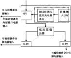
如图2所示为整个系统的电源布置情况,系统可接受外部提供的直流航空电源28V供电,系统电源模块将外部提供的电源通过DC/DC转换成系统内部各模块所需电源,包括+1.2V,+3.3V、+5V,这部分电源分别提供给系统内部不同的功能电源输入端。除信号接口模块采用无源的连接方式外,其余模块的电源供给分别为:触发控制模块+5V,中央处理模块I/O供电+3.3V,内核供电+1.2V,高速存储器模块以及系统与外部的交互接口使用+5V电源。考虑系统的集成,+5V电源由DC/DC模块转换得到外,其余低压电源均通过小体积贴片的低压差稳压器实现。同时,系统也可支持5V电源的直接供电。由于系统功耗低的特点,也可以选用电池供电或者结合能量回收的方式对系统进行供电。 As shown in Figure 2, the power supply layout of the entire system is shown. The system can accept the external DC aviation power supply of 28V. V, +3.3V, +5V, this part of the power supply is provided to the different function power input terminals inside the system respectively. Except that the signal interface module adopts passive connection mode, the power supplies of other modules are: trigger control module +5V, central processing module I/O power supply +3.3V, core power supply +1.2V, high-speed memory module and system and external The interactive interface uses +5V power supply. Considering the integration of the system, the +5V power supply is converted by the DC/DC module, and the rest of the low-voltage power supply is realized by a low-dropout regulator with a small size patch. At the same time, the system can also support direct power supply of 5V power supply. Due to the low power consumption of the system, the system can also be powered by a battery or combined with energy recovery. the
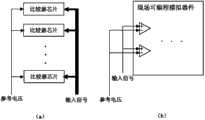
触发控制模块的功能是将压电元件产生的模拟电信号转换为数字信号,数字信号的高低电平由模块中设定的参考电压决定,该参考电压由+5V电压分压所得。当实际应用过程中,对参考电压进行调整,可以控制该系统所要监测冲击能量的等级。触发控制模块内部为n个单限电压比较器。将比较器输出结果作为数字布尔量处理。由于冲击信号通常频段处于0.2Hz到500KHz,故选择高速电压比较器芯片进行触发控制模块的构建,如图3(a)所示,或者也可以使用现场可编程模拟器件FPAA进行电压比较器的搭建,如图3(b)所示。 The function of the trigger control module is to convert the analog electrical signal generated by the piezoelectric element into a digital signal. The high and low levels of the digital signal are determined by the reference voltage set in the module, and the reference voltage is obtained by voltage division of +5V. In the actual application process, adjusting the reference voltage can control the level of impact energy to be monitored by the system. There are n single-limit voltage comparators inside the trigger control module. Treat the comparator output as a digital boolean. Since the impact signal usually has a frequency range of 0.2Hz to 500KHz, a high-speed voltage comparator chip is selected to build the trigger control module, as shown in Figure 3(a), or the field programmable analog device FPAA can be used to build the voltage comparator , as shown in Figure 3(b). the
中央处理模块采用现场可编程门阵列器件FPGA实现,它主要包括:逻辑控制模块、自检模块、区域定位模块、通讯模块以及数据存储器模块。其中数据存储器采用FPGA自带的参数化模块库构建完成。 The central processing module is implemented by a field programmable gate array device FPGA, which mainly includes: a logic control module, a self-check module, an area positioning module, a communication module and a data memory module. Among them, the data memory is constructed using the parameterized module library that comes with the FPGA. the
数据存储器包括n个数据缓存器和一个有效数据和区域定位结果存储器。n个数据缓存器用于记录每次冲击事件发生时所有传感器通路上一定时间范围内的数字布尔量信 号,有效数据和区域定位结果存储器用于在每次冲击事件发生时,根据区域定位模块的定位结果,将有效传感器通路对应的数据缓存器内部数据和区域定位结果存储于其中。 The data storage includes n data buffers and a valid data and area positioning result storage. n data buffers are used to record the digital boolean signals within a certain time range on all sensor paths when each impact event occurs, and the valid data and area positioning result memory are used to locate the area according to the area positioning module when each impact event occurs The positioning result stores the internal data of the data buffer corresponding to the effective sensor path and the area positioning result. the
区域定位模块通过对n个数据缓存器中的布尔量数据进行处理,得出离冲击位置最近的几个传感器通道号,并将处理结果实时输出给逻辑控制模块。 The area positioning module processes the Boolean data in n data buffers to obtain the channel numbers of the sensors closest to the impact position, and outputs the processing results to the logic control module in real time. the
自检模块作为绝对独立的硬件线程在FPGA内部工作,通过模块中的定时器设置,等间隔地对整个系统进行自检测工作,检测内容包括传感器和硬件系统自身。若发现传感器失效,则将该传感器从阵列结构移除,如硬件系统自身出错,则终止工作,并发出警报。 The self-inspection module works inside the FPGA as an absolutely independent hardware thread. Through the timer setting in the module, the self-inspection of the entire system is performed at equal intervals. The detection content includes the sensor and the hardware system itself. If it is found that the sensor fails, the sensor will be removed from the array structure. If the hardware system itself fails, the work will be terminated and an alarm will be issued. the
图4所示为逻辑控制模块的结构框图,它包括有:时钟产生模块、触发判断模块、连续采集模块、信息转存模块、信息传输模块和事件处理模块组成。首先,信息传输模块获取外部响应的配置信息,进行初始化配置;触发判断模块对输入进FPGA的n路数字信号进行高电平检测,当出现高电平信号时,启动连续采集模块,以一定的采样率对数字信号进行采集,采集到的数字信号存储于FPGA内部构建的数据缓存器中。信息转存模块根据区域定位模块提供的定位信息对有效传感器对应数字信号及区域定位结果进行转存,并使用信息传输模块将其存储至外部大容量存储器中。时钟产生模块用于产生其余各模块所需的时钟信号。事件处理模块主要是对自检模块产生的结果及其余模块的反馈信号进行处理。 Figure 4 shows the structural block diagram of the logic control module, which includes: a clock generation module, a trigger judgment module, a continuous acquisition module, an information transfer module, an information transmission module and an event processing module. First, the information transmission module obtains the configuration information of the external response, and performs initial configuration; the trigger judgment module detects the high level of the n-channel digital signals input into the FPGA, and when a high level signal occurs, the continuous acquisition module is started, with a certain The sampling rate collects the digital signal, and the collected digital signal is stored in the data buffer built inside the FPGA. The information dumping module dumps the corresponding digital signals of the effective sensors and the regional positioning results according to the positioning information provided by the regional positioning module, and uses the information transmission module to store them in an external large-capacity memory. The clock generating module is used to generate clock signals required by other modules. The event processing module mainly processes the results generated by the self-test module and the feedback signals of other modules. the
通讯模块为无线射频模块和外部交互接口服务,将需要传递的数据按照一定协议格式和时序发送给外部模块。 The communication module serves the radio frequency module and the external interactive interface, and sends the data to be transmitted to the external module according to a certain protocol format and timing. the
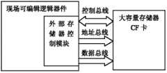
外部大容量高速数据存储器采用CF卡实现。CF卡功耗较低,容量相对较大,速度快,价格便宜。如图5所示,通过外部存储器控制模块内地址通路模块、控制命令产生模块和数据通路模块相互配合,为CF卡提供正确的地址、数据和控制命令,从而将采集得到的数据源源不断的保存入该器件中。 The external large-capacity high-speed data storage is realized by CF card. CF card has low power consumption, relatively large capacity, fast speed and cheap price. As shown in Figure 5, through the cooperation of the address path module, control command generation module and data path module in the external memory control module, the correct address, data and control commands are provided for the CF card, so that the collected data is continuously saved into the device. the
图6为无线射频模块的工作模式,该模块与外部控制中心提供的无线基站通信,在系统接收到相关指令时,无线射频模块将数据发送至基站,当监测结构庞大,使用若干冲击监测设备进行组网工作时,无线传输的方式可以规避系统与外部控制中心复杂连线的问题。通过基于IEEE802.15.4预先设计的网络通信协议将数据传递到基站,最终移交外部控制中心进行分析处理。 Figure 6 shows the working mode of the wireless radio frequency module. This module communicates with the wireless base station provided by the external control center. When the system receives relevant instructions, the wireless radio frequency module sends data to the base station. When the monitoring structure is huge, several shock monitoring devices are used for monitoring When working in a network, the wireless transmission method can avoid the problem of complex connection between the system and the external control center. The data is transmitted to the base station through a pre-designed network communication protocol based on IEEE802.15.4, and finally handed over to the external control center for analysis and processing. the
如图7所示为所设计系统与外部总线的通讯连接方式。包括有CAN总线的通信方式、 1553B的通信方式、1773的光通信方式和RS232串行的通信方式。当外部设计使用CAN总线通信模式时,系统采用内部的CAN控制器和CAN总线收发器将完成两者之间的命令和数据交互。当外部设计使用1553B总线通信模式时,系统内部采用1553B总线协议芯片完成系统与外部的交互。当外部设计使用1773光总线通信模式时,系统内部采用1773光总线控制芯片完成系统与外部的交互。 As shown in Figure 7, it is the communication connection mode between the designed system and the external bus. Including CAN bus communication mode, 1553B communication mode, 1773 optical communication mode and RS232 serial communication mode. When the external design uses the CAN bus communication mode, the system uses the internal CAN controller and CAN bus transceiver to complete the command and data interaction between the two. When the external design uses the 1553B bus communication mode, the system uses the 1553B bus protocol chip to complete the interaction between the system and the outside. When the external design uses the 1773 optical bus communication mode, the system uses the 1773 optical bus control chip to complete the interaction between the system and the outside. the
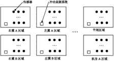
本实施例如图8所示。整体硬件集成在嵌入计算机整体式铝合金散热外壳内,各个模块以堆叠方式相互支撑。各个板卡从上往下堆叠次序依次为系统电源模块组成的1号板,触发控制模块和中央处理模块和大容量存储器组成的2号板,无线射频组成的3号板、由CAN控制器和收发器组成的4号板和1553B协议芯片、1773光总线控制芯片和串口通信芯片组成的5号板。其中,3、4、5号板卡为可选板卡,根据特定的应用场合进行合理的配置。压电传感器信号经由信号接口模块电路板,从设备机箱外侧引入。实际系统设备体积做到80mm*60mm*30mm。图9为系统以组网的形式完成大规模传感器阵列监测的结构示意图。 This embodiment is shown in Figure 8. The overall hardware is integrated in the integrated aluminum alloy cooling case embedded in the computer, and each module supports each other in a stacked manner. The stacking order of each board from top to bottom is board No. 1 composed of system power module, board No. 2 composed of trigger control module, central processing module and large-capacity memory, board No. No. 4 board composed of transceiver and No. 5 board composed of 1553B protocol chip, 1773 optical bus control chip and serial port communication chip. Among them, No. 3, 4, and 5 boards are optional boards, which can be reasonably configured according to specific applications. The piezoelectric sensor signal is introduced from the outside of the equipment case via the signal interface module circuit board. The actual system equipment volume is 80mm*60mm*30mm. Fig. 9 is a schematic structural diagram of the system completing large-scale sensor array monitoring in the form of networking. the
实施方式二: Implementation mode two:
实施方式二与实施方式一采用相同的设计原理,但是在具体的物理实现方面有所不同。实施方式二的电路制版采用柔性电路板制作,并将压电传感器集成进柔性电路板当中,形成自带处理电路的压电夹层的整体概念。将柔性板整体粘贴于被监测结构表面,省去了系统与压电传感器连线过程,增强了系统的可靠性。图10为实施方式二的整体结构示意图。
Claims (6)
Translated fromChinesePriority Applications (1)
| Application Number | Priority Date | Filing Date | Title |
|---|---|---|---|
| CN 201110192185CN102288346B (en) | 2011-07-11 | 2011-07-11 | Miniaturized digital large-scale sensor array impact monitoring system |
Applications Claiming Priority (1)
| Application Number | Priority Date | Filing Date | Title |
|---|---|---|---|
| CN 201110192185CN102288346B (en) | 2011-07-11 | 2011-07-11 | Miniaturized digital large-scale sensor array impact monitoring system |
Publications (2)
| Publication Number | Publication Date |
|---|---|
| CN102288346Atrue CN102288346A (en) | 2011-12-21 |
| CN102288346B CN102288346B (en) | 2013-07-03 |
Family
ID=45334952
Family Applications (1)
| Application Number | Title | Priority Date | Filing Date |
|---|---|---|---|
| CN 201110192185ActiveCN102288346B (en) | 2011-07-11 | 2011-07-11 | Miniaturized digital large-scale sensor array impact monitoring system |
Country Status (1)
| Country | Link |
|---|---|
| CN (1) | CN102288346B (en) |
Cited By (10)
| Publication number | Priority date | Publication date | Assignee | Title |
|---|---|---|---|---|
| CN103149383A (en)* | 2013-02-07 | 2013-06-12 | 南京航空航天大学 | Structure impact zone image alarm method based on number sequence and time reversal |
| CN104678942A (en)* | 2014-08-26 | 2015-06-03 | 北京天高智机技术开发公司 | Novel full-digital measurement and control method |
| CN105241957A (en)* | 2015-10-30 | 2016-01-13 | 常州飞智传感科技有限公司 | Automated rapid assessment method and system for structural remaining life |
| CN105842542A (en)* | 2016-04-13 | 2016-08-10 | 云南电网有限责任公司电力科学研究院 | Grounding device impacted grounding resistance measuring method and system |
| CN107317874A (en)* | 2017-07-26 | 2017-11-03 | 中国航空工业集团公司西安飞机设计研究所 | A kind of network design method of airborne many topological double crossing over structures |
| CN108169037A (en)* | 2017-12-15 | 2018-06-15 | 南京航空航天大学 | Continuous heterogeneous large area Impact monitoring network and shock zone localization method |
| CN111324070A (en)* | 2020-03-04 | 2020-06-23 | 明峰医疗系统股份有限公司 | Debugging method of CT serial detector module cluster based on FPGA |
| CN111337964A (en)* | 2020-03-25 | 2020-06-26 | 西安微电子技术研究所 | Multifunctional real-time measurement storage device for high-dynamic moving objects |
| CN113720878A (en)* | 2021-08-16 | 2021-11-30 | 中国飞机强度研究所 | Combined piezoelectric intelligent interlayer and connecting device thereof |
| CN114060093A (en)* | 2021-11-24 | 2022-02-18 | 天地科技股份有限公司 | Rock burst data acquisition substation and acquisition method |
Citations (4)
| Publication number | Priority date | Publication date | Assignee | Title |
|---|---|---|---|---|
| WO2005116603A1 (en)* | 2004-05-25 | 2005-12-08 | Tirestamp Inc. | A universal tire pressure monitoring system and wireless receiver |
| CN101000293A (en)* | 2007-01-18 | 2007-07-18 | 南京航空航天大学 | Investigating method for impact position of aircraft laminated structure and its investigating device |
| CN101701880A (en)* | 2009-08-05 | 2010-05-05 | 南京航空航天大学 | Embedded Aircraft Active and Passive Structural Health Monitoring System |
| CN101807953A (en)* | 2010-02-10 | 2010-08-18 | 南京航空航天大学 | Multichannel data integration center node of wireless sensor network |
- 2011
- 2011-07-11CNCN 201110192185patent/CN102288346B/enactiveActive
Patent Citations (4)
| Publication number | Priority date | Publication date | Assignee | Title |
|---|---|---|---|---|
| WO2005116603A1 (en)* | 2004-05-25 | 2005-12-08 | Tirestamp Inc. | A universal tire pressure monitoring system and wireless receiver |
| CN101000293A (en)* | 2007-01-18 | 2007-07-18 | 南京航空航天大学 | Investigating method for impact position of aircraft laminated structure and its investigating device |
| CN101701880A (en)* | 2009-08-05 | 2010-05-05 | 南京航空航天大学 | Embedded Aircraft Active and Passive Structural Health Monitoring System |
| CN101807953A (en)* | 2010-02-10 | 2010-08-18 | 南京航空航天大学 | Multichannel data integration center node of wireless sensor network |
Cited By (13)
| Publication number | Priority date | Publication date | Assignee | Title |
|---|---|---|---|---|
| CN103149383B (en)* | 2013-02-07 | 2015-07-01 | 南京航空航天大学 | Structure impact zone image alarm method based on number sequence and time reversal |
| CN103149383A (en)* | 2013-02-07 | 2013-06-12 | 南京航空航天大学 | Structure impact zone image alarm method based on number sequence and time reversal |
| CN104678942A (en)* | 2014-08-26 | 2015-06-03 | 北京天高智机技术开发公司 | Novel full-digital measurement and control method |
| CN104678942B (en)* | 2014-08-26 | 2017-10-24 | 北京天高智机技术开发公司 | A kind of totally digitilized investigating method |
| CN105241957B (en)* | 2015-10-30 | 2019-04-12 | 常州飞智传感科技有限公司 | A kind of structure residual life automation fast evaluation method and system |
| CN105241957A (en)* | 2015-10-30 | 2016-01-13 | 常州飞智传感科技有限公司 | Automated rapid assessment method and system for structural remaining life |
| CN105842542A (en)* | 2016-04-13 | 2016-08-10 | 云南电网有限责任公司电力科学研究院 | Grounding device impacted grounding resistance measuring method and system |
| CN107317874A (en)* | 2017-07-26 | 2017-11-03 | 中国航空工业集团公司西安飞机设计研究所 | A kind of network design method of airborne many topological double crossing over structures |
| CN108169037A (en)* | 2017-12-15 | 2018-06-15 | 南京航空航天大学 | Continuous heterogeneous large area Impact monitoring network and shock zone localization method |
| CN111324070A (en)* | 2020-03-04 | 2020-06-23 | 明峰医疗系统股份有限公司 | Debugging method of CT serial detector module cluster based on FPGA |
| CN111337964A (en)* | 2020-03-25 | 2020-06-26 | 西安微电子技术研究所 | Multifunctional real-time measurement storage device for high-dynamic moving objects |
| CN113720878A (en)* | 2021-08-16 | 2021-11-30 | 中国飞机强度研究所 | Combined piezoelectric intelligent interlayer and connecting device thereof |
| CN114060093A (en)* | 2021-11-24 | 2022-02-18 | 天地科技股份有限公司 | Rock burst data acquisition substation and acquisition method |
Also Published As
| Publication number | Publication date |
|---|---|
| CN102288346B (en) | 2013-07-03 |
Similar Documents
| Publication | Publication Date | Title |
|---|---|---|
| CN102288346A (en) | Miniaturized digital large-scale sensor array impact monitoring system | |
| Fu et al. | An event-triggered energy-efficient wireless structural health monitoring system for impact detection in composite airframes | |
| US10073811B2 (en) | Systems and methods for monitoring health of vibration damping components | |
| CN202394111U (en) | Manned carrier rocket fault detection system | |
| CN110488630B (en) | Test system and test method for controlling stability-increasing flight control computer | |
| CN104914872A (en) | Sensor dual-redundancy flight control computer system suitable for small civilian unmanned aerial vehicle | |
| CN102081145B (en) | Functional verification platform of battery management system | |
| CN204286792U (en) | A kind of two remaining Aerial weapon equipment state monitoring apparatus | |
| CN104181000A (en) | Structural health monitoring system for aircraft | |
| CN103760886A (en) | Newly-developed aviation electronic product hardware comprehensive FMECA method | |
| CN104199440B (en) | Four-unit three-bus redundancy heterogeneous GNC (guidance navigation control) system | |
| CN106526388B (en) | Unmanned aerial vehicle airborne avionics testing system and testing method | |
| CN109031131B (en) | The real-time host system of the heterogeneous polynuclear of battery testing and analog meter and method | |
| CN102183350B (en) | Real-time impact monitoring instrument and method of large-scale aviation structure | |
| CN204189212U (en) | A kind of protection composite record device | |
| CN103836767A (en) | Ground operation aircraft passenger cabin environment management and control system | |
| WO2017067034A1 (en) | Microminiature impact monitoring system with ultra-low power consumption based on diode array digitization | |
| CN105004463A (en) | Piston type propeller engine thrust measuring method and piston type propeller engine thrust measuring device | |
| Li et al. | Design of an integrated ultrasonic guided wave structural health monitoring system based on multi-channel high-speed synchronous acquisition | |
| Zhang et al. | Dual redundant flight control system design for microminiature UAV | |
| CN205280908U (en) | New energy automobile battery package test verifying attachment | |
| CN205193546U (en) | Condition monitoring system based on model aeroplane and model ship aircraft | |
| CN103837361B (en) | Compound substance machinery syndeton comprehensive monitor system | |
| CN103926861B (en) | Intelligent interface adapter of universal test equipment for aviation ammunition | |
| CN108839815A (en) | A kind of prolongable distributed aeronautic structure life monitoring device of airborne multichannel |
Legal Events
| Date | Code | Title | Description |
|---|---|---|---|
| C06 | Publication | ||
| PB01 | Publication | ||
| C10 | Entry into substantive examination | ||
| SE01 | Entry into force of request for substantive examination | ||
| C14 | Grant of patent or utility model | ||
| GR01 | Patent grant |