CN102287527A - Transmission shift mechanism - Google Patents
Transmission shift mechanismDownload PDFInfo
- Publication number
- CN102287527A CN102287527ACN2011102099910ACN201110209991ACN102287527ACN 102287527 ACN102287527 ACN 102287527ACN 2011102099910 ACN2011102099910 ACN 2011102099910ACN 201110209991 ACN201110209991 ACN 201110209991ACN 102287527 ACN102287527 ACN 102287527A
- Authority
- CN
- China
- Prior art keywords
- transmission
- shift
- fork
- shifter
- driven gear
- Prior art date
- Legal status (The legal status is an assumption and is not a legal conclusion. Google has not performed a legal analysis and makes no representation as to the accuracy of the status listed.)
- Pending
Links
Images

Classifications
- F—MECHANICAL ENGINEERING; LIGHTING; HEATING; WEAPONS; BLASTING
- F16—ENGINEERING ELEMENTS AND UNITS; GENERAL MEASURES FOR PRODUCING AND MAINTAINING EFFECTIVE FUNCTIONING OF MACHINES OR INSTALLATIONS; THERMAL INSULATION IN GENERAL
- F16H—GEARING
- F16H63/00—Control outputs from the control unit to change-speed- or reversing-gearings for conveying rotary motion or to other devices than the final output mechanism
- F16H63/02—Final output mechanisms therefor; Actuating means for the final output mechanisms
- F16H63/08—Multiple final output mechanisms being moved by a single common final actuating mechanism
- F16H63/16—Multiple final output mechanisms being moved by a single common final actuating mechanism the final output mechanisms being successively actuated by progressive movement of the final actuating mechanism
- F16H63/18—Multiple final output mechanisms being moved by a single common final actuating mechanism the final output mechanisms being successively actuated by progressive movement of the final actuating mechanism the final actuating mechanism comprising cams
Landscapes
- Engineering & Computer Science (AREA)
- General Engineering & Computer Science (AREA)
- Mechanical Engineering (AREA)
- Gear-Shifting Mechanisms (AREA)
Abstract
Description
Translated fromChinese技术领域technical field
本发明属于汽车技术领域,涉及一种汽车变速器,特别涉及一种变速器换挡机构。The invention belongs to the technical field of automobiles, relates to an automobile transmission, in particular to a transmission shift mechanism.
背景技术Background technique
汽车变速器必须配备换挡机构以实现变速器的换挡工作,传统的换挡机构是采用换挡指拨动换挡拨叉组件上的叉口架达到换挡的目的,这种结构需要多个换挡拨叉组件,且由于拨叉叉轴组件是一体的,在换挡时由换挡指带动换挡拨叉做轴向运动,会引起换挡卡滞现象。The automobile transmission must be equipped with a shifting mechanism to realize the shifting work of the transmission. The traditional shifting mechanism uses the shift finger to toggle the fork frame on the shift fork assembly to achieve the purpose of shifting. This structure requires multiple shifting The gear shift fork assembly, and because the shift fork shaft assembly is integrated, the shift finger drives the shift fork to move axially when shifting gears, which will cause shift sticking.
针对存在的问题,人们设计了各种换挡机构,有些还申请了专利,例如中国专利文献资料公开了一种变速器换挡机构[200810241299.4;公开号:CN101457832A],其包括选挡臂、换挡臂、壳体、选换挡轴、上换挡指和下换挡指;选换挡轴插入壳体内,换挡臂与选换挡轴刚性连接,选挡臂与选换挡轴轴向往复随动旋转活动连接;选换挡轴上刚性连接上换挡指和下换挡指;在所选换挡轴上设置互锁板,互锁板为角钢形,选换挡轴从互锁板的上端头插入从互锁板下端头伸出,互锁板与选换挡轴轴向随动旋转活动连接,在互锁板上对应于选换挡轴上的上换挡指和下换挡指位置分别设置有上换挡指孔和下换挡指孔。In view of existing problems, people have designed various shifting mechanisms, and some have also applied for patents. For example, Chinese patent literature discloses a transmission shifting mechanism [200810241299.4; publication number: CN101457832A], which includes a gear selection arm, a gear shifting arm, housing, selector shift shaft, upper shift finger and lower shift finger; the selector shift shaft is inserted into the housing, the shift arm is rigidly connected to the selector shift shaft, and the shift arm and select shift shaft reciprocate axially Follow-up rotation movable connection; rigidly connect the upper shift finger and the lower shift finger on the selected shift shaft; set an interlock plate on the selected shift shaft, the interlock plate is an angle steel shape, and select the shift shaft from the interlock plate The upper end of the interlocking plate is inserted and protrudes from the lower end of the interlocking plate, and the interlocking plate is movably connected with the axial follow-up rotation of the shifting shaft, and the interlocking plate corresponds to the upper shifting finger and the lower shifting finger on the shifting shaft The finger positions are respectively provided with an upper shift finger hole and a lower shift finger hole.
上述专利通过互锁板控制选换挡轴上的换挡指只带动一个拨叉转动,可以解决换挡卡滞问题,但是结构较为复杂,而且其在换挡时操作选挡臂,带动选换挡轴和互锁板移动以完成选挡,这样就必须在变速器壳体上的选换挡轴两端预留大于换挡行程的空间,这样就增加了变速器的轴向尺寸,结构复杂且占用空间较大,不适合轻便微型轿车。The above-mentioned patent uses the interlock plate to control the shift finger on the selector shaft to only drive one shift fork to rotate, which can solve the problem of shift sticking, but the structure is relatively complicated, and it operates the selector arm when shifting to drive the selector. The gear shaft and the interlock plate move to complete the gear selection, so that a space larger than the shift stroke must be reserved at both ends of the gear selection shaft on the transmission case, which increases the axial size of the transmission, and the structure is complex and takes up The space is large, not suitable for light and small cars.
发明内容Contents of the invention
本发明的目的是针对现有的技术存在上述问题,提出了一种占用空间较小、结构简单且适用性较强的变速器换挡机构。The purpose of the present invention is to solve the above-mentioned problems in the prior art, and propose a transmission shifting mechanism that occupies less space, has a simple structure and has strong applicability.
本发明的目的可通过下列技术方案来实现:一种变速器换挡机构,包括一根固连在变速器壳体上的换挡轴和套在换挡轴上的拨叉,其特征在于,所述的变速器壳体内还具有呈圆柱状的轮毂,所述轮毂与动力输入端相连,所述轮毂外侧具有与拔叉数量相同且位置对应的导轨,上述的拔叉一部分与导轨连接。The purpose of the present invention can be achieved through the following technical solutions: a transmission shift mechanism, comprising a shift shaft fixedly connected to the transmission housing and a shift fork sleeved on the shift shaft, characterized in that the There is also a cylindrical hub in the transmission housing, the hub is connected to the power input end, and the outer side of the hub has guide rails with the same number and corresponding positions as the forks, and a part of the above-mentioned forks is connected with the guide rails.
在换挡时,动力输入端带动轮毂做旋转运动。由于拨叉空套在换挡轴上,拔叉部分连接在导轨处,轮毂旋转带动导轨做相应的旋转迫使连接在导轨处的部分拨叉做相应的运动。因拨叉空套在换挡轴上,因此拨叉相对换挡轴作上下运动,拨叉的上下运动来拨动同步器齿套以实现变速器同步换挡。When shifting gears, the power input end drives the hub to rotate. Because the shift fork is vacantly sleeved on the shift shaft, the fork part is connected to the guide rail, and the rotation of the wheel hub drives the guide rail to rotate accordingly, forcing the part of the shift fork connected to the guide rail to move accordingly. Because the shift fork is vacantly sleeved on the shift shaft, the shift fork moves up and down relative to the shift shaft, and the up and down motion of the shift fork stirs the synchronizer gear sleeve to realize the synchronous shift of the transmission.
本变速器换挡机构中拨叉部分连接于导轨处,拨叉位置受到导轨限制,因此拨叉的轴向换挡调节精度较高。导轨是对应于各个换挡挡位的,能让其中一个需要换挡的拨叉轴向运动,而使其它拨叉不做轴向运动。In the shifting mechanism of the transmission, the shift fork part is connected to the guide rail, and the position of the shift fork is limited by the guide rail, so the axial shift adjustment accuracy of the shift fork is relatively high. The guide rail is corresponding to each gear shift position, and can allow one of the shift forks that needs to shift to move axially, while keeping the other shift forks from doing axial movement.
在上述的变速器换挡机构中,所述轮毂下端固连有从动齿轮,所述的壳体内还固连有电机,电机转轴上具有主动齿轮且主动齿轮与从动齿轮啮合。电机转轴旋转带动主动齿轮旋转,通过主动齿轮与从动齿轮啮合将动力传递到与从动齿轮相固连的轮毂上,带动上述的导轨旋转,采用齿轮传动具有传动效率高、传动平稳的优点。In the above transmission shifting mechanism, a driven gear is fixedly connected to the lower end of the hub, and a motor is fixedly connected to the housing. A driving gear is provided on the motor shaft and the driving gear meshes with the driven gear. The rotation of the motor shaft drives the driving gear to rotate, and the power is transmitted to the wheel hub fixedly connected with the driven gear through the meshing of the driving gear and the driven gear, which drives the above-mentioned guide rail to rotate. The use of gear transmission has the advantages of high transmission efficiency and stable transmission.
在上述的变速器换挡机构中,所述的从动齿轮与轮毂同轴心设置。从动齿轮与轮毂同心,使轮毂在旋转时能够绕其轴心线旋转。In the above transmission shifting mechanism, the driven gear is coaxially arranged with the hub. The driven gear is concentric with the hub, enabling the hub to rotate around its axis as it rotates.
在上述的变速器换挡机构中,所述的拔叉与导轨之间设有连接销,且连接销的一端与拔叉固连,连接销的另一端嵌于上述的导轨处。因连接销的一端与拔叉固连,连接销的另一端嵌于的导轨处,连接销将轮毂上的动力传递到拔叉上,使拔叉产生相应的运动并拨动同步器齿套以实现变速器同步换挡的目的。In the above transmission shifting mechanism, a connection pin is provided between the fork and the guide rail, and one end of the connection pin is fixedly connected to the fork, and the other end of the connection pin is embedded in the above guide rail. Because one end of the connecting pin is fixedly connected with the fork, and the other end of the connecting pin is embedded in the guide rail, the connecting pin transmits the power on the hub to the fork, so that the fork moves accordingly and the gear sleeve of the synchronizer is moved to Realize the purpose of transmission synchronous shifting.
在上述的变速器换挡机构中,所述的导轨上设有能沿其移动的滑块,上述连接销的另一端与滑块相连。轨上设有与连接销的另一端相连的滑块,因滑块能够更好的在导轨上滑动,具有传动效果好的优点;在一定程度上简化了连接销的结构,使其制造更加方便。In the above transmission shifting mechanism, the guide rail is provided with a slide block that can move along it, and the other end of the connecting pin is connected with the slide block. There is a slider connected to the other end of the connecting pin on the rail. Because the slider can slide better on the guide rail, it has the advantage of good transmission effect; the structure of the connecting pin is simplified to a certain extent, making it more convenient to manufacture .
在上述的变速器换挡机构中,所述的换挡轴上沿其轴向套有三个拔叉,上述轮毂上具有三个与拔叉位置对应的导轨。三个拔叉分别拨动三个同步器齿套以实现多个档位的换挡动作。In the above transmission shifting mechanism, three forks are sleeved on the shift shaft along its axial direction, and the hub has three guide rails corresponding to the positions of the forks. The three forks respectively move the three synchronizer gear sleeves to realize the shift action of multiple gears.
在上述的变速器换挡机构中,所述从动齿轮与变速器壳体之间具有用于将从动齿轮定位的定挡装置。当连接销带动拨叉使拨叉拨动同步器齿套以实现变速器同步换挡后,定挡装置将从动齿轮定位,使定位销定位,从而实现定挡的功能。In the above transmission shifting mechanism, there is a positioning device for positioning the driven gear between the driven gear and the transmission housing. When the connecting pin drives the shift fork to make the shift fork move the synchronizer gear sleeve to realize the synchronous gear shift of the transmission, the gear-fixing device will position the driven gear to position the positioning pin, thereby realizing the function of gear-fixing.
在上述的变速器换挡机构中,所述的定挡装置为从动齿轮端部沿其周向分布的若干定位孔和连接在变速器壳体上的定位件,且定位件能插入上述任意一个定位孔中。定挡时,定位件插入到定位孔中,将从动齿轮定位,每一个挡位都有至少一个定位孔与定位件相对应,使在每一个挡位都能实现定挡功能。In the above-mentioned transmission shifting mechanism, the said positioning device is a plurality of positioning holes distributed along the circumference of the driven gear end and a locating piece connected to the transmission case, and the locating piece can be inserted into any one of the above-mentioned positioning holes. in the hole. When the gear is fixed, the positioning piece is inserted into the positioning hole to position the driven gear, and each gear has at least one positioning hole corresponding to the positioning piece, so that the fixed gear function can be realized in each gear.
在上述的变速器换挡机构中,所述轮毂上导轨上下浮动的尺寸与换挡行程相等。导轨上下浮动的尺寸即使轮毂带动连接销做上下运动的位移,因导轨上下浮动的尺寸与换挡行程相等,因此连接销带动拨叉做换挡动作。In the above transmission shifting mechanism, the size of the upper and lower guide rails on the hub is equal to the shift stroke. The size of the guide rail floating up and down even if the wheel hub drives the connecting pin to move up and down, because the size of the guide rail floating up and down is equal to the shift stroke, so the connecting pin drives the shift fork to do the shifting action.
与现有技术相比,本变速器换挡机构具有以下优点:Compared with the prior art, this transmission shift mechanism has the following advantages:
1、通过设置在分布在轮毂上的导轨带动与拨叉连接的连接销来带动拨叉的移动,具有使换挡轴的安装空间较少,使整个变速器换挡机构更加简单、紧凑;1. The movement of the shift fork is driven by the guide rails arranged on the hub to drive the connecting pins connected with the shift fork, which reduces the installation space of the shift shaft and makes the entire transmission shift mechanism simpler and more compact;
2、通过设置滑块在导轨内滑动带动连接销以及拔叉的上下移动实现换挡功能,具有换挡效果好的优点。2. By setting the slider to slide in the guide rail to drive the connecting pin and the fork to move up and down to realize the shifting function, it has the advantage of good shifting effect.
附图说明Description of drawings
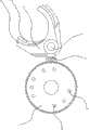
图1是本变速器换挡机构的俯视结构示意图。FIG. 1 is a schematic top view of the transmission shift mechanism.
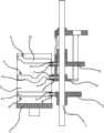
图2是本变速器换挡机构的正视结构示意图。Fig. 2 is a front structural schematic view of the shifting mechanism of the transmission.
图3是本变速器换挡机构的轮毂导轨的展开示意图。Fig. 3 is a schematic diagram of the development of the hub guide rail of the transmission shift mechanism.
图中,1、换挡轴;2、拨叉;3、轮毂;4、导轨;41、凹槽;5、从动齿轮;6、连接销;7、滑块;8、定位孔。Among the figure, 1, shift shaft; 2, shift fork; 3, wheel hub; 4, guide rail; 41, groove; 5, driven gear; 6, connecting pin; 7, slide block; 8, positioning hole.
具体实施方式Detailed ways
以下是本发明的具体实施例并结合附图,对本发明的技术方案作进一步的描述,但本发明并不限于这些实施例。The following are specific embodiments of the present invention and in conjunction with the accompanying drawings, the technical solutions of the present invention are further described, but the present invention is not limited to these embodiments.
如图1至3所示,一种变速器换挡机构,包括一根固连在变速器壳体上的换挡轴1和空套在换挡轴1上的三个拨叉2,变速器壳体内还具有呈圆柱状的轮毂3,轮毂3下端固连有从动齿轮5,从动齿轮5与轮毂3同轴心设置。轮毂3外侧具有三个分别与拔叉位置对应的弯曲的导轨4,导轨4为位于轮毂3外侧的三个凹槽41,导轨4上下浮动的尺寸与换挡行程相等。拔叉与导轨4之间均设有连接销6,连接销6的一端与相应的拔叉固连,连接销6的另一端均固连有嵌于凹槽41上的滑块7。As shown in Figures 1 to 3, a transmission shift mechanism includes a shift shaft 1 fixedly connected to the transmission case and three
壳体内还固连有电机,电机转轴上具有主动齿轮,主动齿轮与从动齿轮5相啮合。从动齿轮5与变速器壳体之间具有用于将从动齿轮5定位的定挡装置。定挡装置为从动齿轮5端部沿其周向分布的八个定位孔8和连接在变速器壳体上的定位件,定位件能插入任意一个定位孔8中。A motor is also fixedly connected in the housing, and a driving gear is arranged on the motor rotating shaft, and the driving gear and the driven gear 5 are meshed. Between the driven gear 5 and the transmission case there is a stopper for positioning the driven gear 5 . The positioning device is eight positioning holes 8 distributed along the circumference of the driven gear 5 end and a positioning piece connected to the transmission housing, and the positioning piece can be inserted into any positioning hole 8 .
在换挡时,电机转动通过主动齿轮与从动齿轮5的啮合带动轮毂3做旋转运动,因从动齿轮5与轮毂3同轴心设置,使轮毂3在旋转时能够绕其轴心线旋转,使得设置在轮毂3上的导轨4作相应的旋转运动。连接销6的一端与相应的拔叉相固连,连接销6的另一端与设置在导轨4上滑块7相连。当轮毂3旋转到一定的角度时,带动其中一块滑块7做一定的轴向滑动而另外两块滑块7不动,并带动相应的连接销6使得拨叉2移动到相应挡位的同步器齿套上实现换挡。当轮毂3旋转的不同角度时,使拨叉2移动到不同的同步器齿套上,从而使实现更换不同的挡位。When shifting gears, the rotation of the motor drives the hub 3 to rotate through the meshing of the driving gear and the driven gear 5. Because the driven gear 5 and the hub 3 are coaxially arranged, the hub 3 can rotate around its axis when rotating. , so that the
当定挡时,电机停止转动,定位件插入到从动齿轮5的定位孔8中,从动齿轮5处于固定状态使滑块7与轮毂3保持相对静止,从而达到固定拨叉2与换挡轴1的位置,实现定挡的作用。当再次需要换挡时,定位件从定位孔8分离处,电机转动再次实现换挡。When the gear is fixed, the motor stops rotating, and the positioning member is inserted into the positioning hole 8 of the driven gear 5, and the driven gear 5 is in a fixed state so that the slider 7 and the wheel hub 3 remain relatively stationary, thereby achieving the fixed
本文中所描述的具体实施例仅仅是对本发明精神作举例说明。本发明所属技术领域的技术人员可以对所描述的具体实施例做各种各样的修改或补充或采用类似的方式替代,但并不会偏离本发明的精神或者超越所附权利要求书所定义的范围。The specific embodiments described herein are merely illustrative of the spirit of the invention. Those skilled in the art to which the present invention belongs can make various modifications or supplements to the described specific embodiments or adopt similar methods to replace them, but they will not deviate from the spirit of the present invention or go beyond the definition of the appended claims range.
尽管本文较多地使用了换挡轴1、拨叉2、轮毂3、导轨4、凹槽41、从动齿轮5、连接销6、滑块7、定位孔8等术语,但并不排除使用其它术语的可能性。使用这些术语仅仅是为了更方便地描述和解释本发明的本质;把它们解释成任何一种附加的限制都是与本发明精神相违背的。Although terms such as shift shaft 1, shift
Claims (9)
Priority Applications (1)
| Application Number | Priority Date | Filing Date | Title |
|---|---|---|---|
| CN2011102099910ACN102287527A (en) | 2011-07-26 | 2011-07-26 | Transmission shift mechanism |
Applications Claiming Priority (1)
| Application Number | Priority Date | Filing Date | Title |
|---|---|---|---|
| CN2011102099910ACN102287527A (en) | 2011-07-26 | 2011-07-26 | Transmission shift mechanism |
Publications (1)
| Publication Number | Publication Date |
|---|---|
| CN102287527Atrue CN102287527A (en) | 2011-12-21 |
Family
ID=45334185
Family Applications (1)
| Application Number | Title | Priority Date | Filing Date |
|---|---|---|---|
| CN2011102099910APendingCN102287527A (en) | 2011-07-26 | 2011-07-26 | Transmission shift mechanism |
Country Status (1)
| Country | Link |
|---|---|
| CN (1) | CN102287527A (en) |
Cited By (12)
| Publication number | Priority date | Publication date | Assignee | Title |
|---|---|---|---|---|
| CN102588581A (en)* | 2012-02-28 | 2012-07-18 | 浙江吉利汽车研究院有限公司 | Gear-changing control device of automobile |
| CN103062395A (en)* | 2013-01-09 | 2013-04-24 | 浙江吉利汽车研究院有限公司杭州分公司 | Gear shifting mechanism of manual transmission |
| CN104265874A (en)* | 2014-09-30 | 2015-01-07 | 东风汽车公司 | Gear shifting control device of electronic control actuator |
| CN104781592A (en)* | 2012-09-10 | 2015-07-15 | Dti集团有限公司 | Driveline for a vehicle |
| CN106609842A (en)* | 2017-01-12 | 2017-05-03 | 西南大学 | Gearshift mechanism, gearbox and electric vehicle |
| CN107208786A (en)* | 2015-04-17 | 2017-09-26 | 宝马股份公司 | Method for controlling gear shifting in an unsynchronized claw transmission |
| CN107269831A (en)* | 2017-07-13 | 2017-10-20 | 吉林大学 | Single motor gearshift of pure electric automobile electric control mechanical type automatic speed variator |
| CN108730512A (en)* | 2018-06-15 | 2018-11-02 | 山东理工大学 | Shifting vehicle gearbox axis triangle art chute designs method |
| CN108999967A (en)* | 2018-06-15 | 2018-12-14 | 山东理工大学 | Shifting vehicle gearbox axis triangle sliding slot optimum design method |
| CN109027220A (en)* | 2018-09-13 | 2018-12-18 | 山东理工大学 | Shifting vehicle gearbox axis circle contour line art chute designs method |
| CN110778713A (en)* | 2019-12-10 | 2020-02-11 | 重庆青山工业有限责任公司 | Transmission shift park actuator |
| CN111173925A (en)* | 2020-01-22 | 2020-05-19 | 凯博易控车辆科技(苏州)股份有限公司 | Gear shifting mechanism and gear shifting method of transmission and vehicle |
Citations (5)
| Publication number | Priority date | Publication date | Assignee | Title |
|---|---|---|---|---|
| CN2806895Y (en)* | 2005-06-28 | 2006-08-16 | 刘国杰 | Motorcycle engine gearshift mechanism |
| KR20080065365A (en)* | 2007-01-09 | 2008-07-14 | 위아 주식회사 | Car transmission |
| CN201228767Y (en)* | 2008-06-16 | 2009-04-29 | 光阳工业股份有限公司 | Gear shift structure for vehicle |
| CN101625024A (en)* | 2008-07-10 | 2010-01-13 | C.R.F.阿西安尼顾问公司 | Sequential control device |
| US7963183B2 (en)* | 2009-04-06 | 2011-06-21 | Dean Pick | Sequential transmission shift system |
- 2011
- 2011-07-26CNCN2011102099910Apatent/CN102287527A/enactivePending
Patent Citations (5)
| Publication number | Priority date | Publication date | Assignee | Title |
|---|---|---|---|---|
| CN2806895Y (en)* | 2005-06-28 | 2006-08-16 | 刘国杰 | Motorcycle engine gearshift mechanism |
| KR20080065365A (en)* | 2007-01-09 | 2008-07-14 | 위아 주식회사 | Car transmission |
| CN201228767Y (en)* | 2008-06-16 | 2009-04-29 | 光阳工业股份有限公司 | Gear shift structure for vehicle |
| CN101625024A (en)* | 2008-07-10 | 2010-01-13 | C.R.F.阿西安尼顾问公司 | Sequential control device |
| US7963183B2 (en)* | 2009-04-06 | 2011-06-21 | Dean Pick | Sequential transmission shift system |
Cited By (18)
| Publication number | Priority date | Publication date | Assignee | Title |
|---|---|---|---|---|
| CN102588581B (en)* | 2012-02-28 | 2015-03-04 | 浙江吉利汽车研究院有限公司 | Gear-changing control device of automobile |
| CN102588581A (en)* | 2012-02-28 | 2012-07-18 | 浙江吉利汽车研究院有限公司 | Gear-changing control device of automobile |
| CN104781592B (en)* | 2012-09-10 | 2017-08-22 | Dti集团有限公司 | drive system for vehicle |
| CN104781592A (en)* | 2012-09-10 | 2015-07-15 | Dti集团有限公司 | Driveline for a vehicle |
| US9664280B2 (en) | 2012-09-10 | 2017-05-30 | Dti Group B.V. | Driveline for a vehicle |
| CN103062395B (en)* | 2013-01-09 | 2015-08-05 | 浙江吉利汽车研究院有限公司杭州分公司 | A kind of manual transmission gearshift |
| CN103062395A (en)* | 2013-01-09 | 2013-04-24 | 浙江吉利汽车研究院有限公司杭州分公司 | Gear shifting mechanism of manual transmission |
| CN104265874A (en)* | 2014-09-30 | 2015-01-07 | 东风汽车公司 | Gear shifting control device of electronic control actuator |
| CN107208786B (en)* | 2015-04-17 | 2019-02-22 | 宝马股份公司 | Method for controlling shifting in an asynchronous claw transmission |
| CN107208786A (en)* | 2015-04-17 | 2017-09-26 | 宝马股份公司 | Method for controlling gear shifting in an unsynchronized claw transmission |
| US10408147B2 (en) | 2015-04-17 | 2019-09-10 | Bayerische Motoren Werke Aktiengesellschaft | Method for controlling a gear change in the case of a non-synchronized dog-shift transmission |
| CN106609842A (en)* | 2017-01-12 | 2017-05-03 | 西南大学 | Gearshift mechanism, gearbox and electric vehicle |
| CN107269831A (en)* | 2017-07-13 | 2017-10-20 | 吉林大学 | Single motor gearshift of pure electric automobile electric control mechanical type automatic speed variator |
| CN108999967A (en)* | 2018-06-15 | 2018-12-14 | 山东理工大学 | Shifting vehicle gearbox axis triangle sliding slot optimum design method |
| CN108730512A (en)* | 2018-06-15 | 2018-11-02 | 山东理工大学 | Shifting vehicle gearbox axis triangle art chute designs method |
| CN109027220A (en)* | 2018-09-13 | 2018-12-18 | 山东理工大学 | Shifting vehicle gearbox axis circle contour line art chute designs method |
| CN110778713A (en)* | 2019-12-10 | 2020-02-11 | 重庆青山工业有限责任公司 | Transmission shift park actuator |
| CN111173925A (en)* | 2020-01-22 | 2020-05-19 | 凯博易控车辆科技(苏州)股份有限公司 | Gear shifting mechanism and gear shifting method of transmission and vehicle |
Similar Documents
| Publication | Publication Date | Title |
|---|---|---|
| CN102287527A (en) | Transmission shift mechanism | |
| CN101555942B (en) | Gear shift mechanism of six-speed automobile speed changer | |
| CN106801742B (en) | Transmission device of double clutch transmission | |
| CN101625024B (en) | Sequential control device | |
| CN201074673Y (en) | Control mechanism of gearbox | |
| CN102758912A (en) | Gear shift system for electric vehicle | |
| CN102588581B (en) | Gear-changing control device of automobile | |
| CN101290065A (en) | Gear selector for manual transmission | |
| CN203363113U (en) | AMT gear selecting and shifting operating mechanism | |
| CN103185135A (en) | Drive mechanism of automated electrically-controlled mechanical transmission | |
| CN111059268B (en) | Gear shifting and parking structure of gearbox and execution method | |
| CN102338213A (en) | Novel parking braking mechanism of dual clutch automatic transmission (DCT) | |
| CN112728064A (en) | Transmission gear-shifting parking structure and new energy automobile | |
| KR101512226B1 (en) | Shifting lever assembly using one shaft for agricultural machine | |
| CN104913049B (en) | Speed changer | |
| CN107269831A (en) | Single motor gearshift of pure electric automobile electric control mechanical type automatic speed variator | |
| CN205806457U (en) | Single axle gearshift mechanism of automotive transmission | |
| KR20090040074A (en) | Shift Actuator for Dual Clutch Transmission | |
| CN101328973B (en) | Double-clutch automatic transmission pre-gear shift mechanism | |
| CN101457832B (en) | Shifter of transmission | |
| CN106989166A (en) | New-energy automobile electric-controlled mechanical linear shift automatic transmission | |
| CN204921958U (en) | Fork assembly that shifts that steps down is obstructed | |
| CN103075510A (en) | Speed changer manipulating mechanism with fan-shaped interlocking plate | |
| CN207500457U (en) | The single motor gearshift of pure electric automobile electric control mechanical type automatic speed variator | |
| CN102678901A (en) | Gear selecting and shifting mechanism for cam |
Legal Events
| Date | Code | Title | Description |
|---|---|---|---|
| C06 | Publication | ||
| PB01 | Publication | ||
| C10 | Entry into substantive examination | ||
| SE01 | Entry into force of request for substantive examination | ||
| C12 | Rejection of a patent application after its publication | ||
| RJ01 | Rejection of invention patent application after publication | Application publication date:20111221 |