CN102283679B - Ultrasonic imaging system for elasticity measurement and method for measuring elasticity of biological tissue - Google Patents
Ultrasonic imaging system for elasticity measurement and method for measuring elasticity of biological tissueDownload PDFInfo
- Publication number
- CN102283679B CN102283679BCN201110222813.1ACN201110222813ACN102283679BCN 102283679 BCN102283679 BCN 102283679BCN 201110222813 ACN201110222813 ACN 201110222813ACN 102283679 BCN102283679 BCN 102283679B
- Authority
- CN
- China
- Prior art keywords
- ultrasonic
- transducer array
- tissue
- biological tissue
- low
- Prior art date
- Legal status (The legal status is an assumption and is not a legal conclusion. Google has not performed a legal analysis and makes no representation as to the accuracy of the status listed.)
- Active
Links
- 238000000034methodMethods0.000titleclaimsabstractdescription58
- 238000003384imaging methodMethods0.000titleclaimsabstractdescription55
- 238000005259measurementMethods0.000titleclaimsabstractdescription25
- 238000012545processingMethods0.000claimsabstractdescription40
- 238000002604ultrasonographyMethods0.000claimsabstractdescription40
- 238000006073displacement reactionMethods0.000claimsabstractdescription36
- 230000010355oscillationEffects0.000claimsabstractdescription33
- 230000008569processEffects0.000claimsabstractdescription30
- 239000000523sampleSubstances0.000claimsabstractdescription18
- 108010076504Protein Sorting SignalsProteins0.000claimsdescription19
- 238000001914filtrationMethods0.000claimsdescription17
- 239000008280bloodSubstances0.000claims7
- 210000004369bloodAnatomy0.000claims7
- 238000010008shearingMethods0.000claims5
- 230000008520organizationEffects0.000claims2
- 230000015572biosynthetic processEffects0.000claims1
- 238000004891communicationMethods0.000claims1
- 238000003759clinical diagnosisMethods0.000abstractdescription4
- 210000001519tissueAnatomy0.000description99
- 238000002091elastographyMethods0.000description16
- 238000012285ultrasound imagingMethods0.000description9
- 239000011159matrix materialSubstances0.000description8
- 208000019425cirrhosis of liverDiseases0.000description6
- 238000001514detection methodMethods0.000description6
- 210000005228liver tissueAnatomy0.000description5
- 230000001902propagating effectEffects0.000description5
- 238000004458analytical methodMethods0.000description4
- 230000005540biological transmissionEffects0.000description4
- 238000004364calculation methodMethods0.000description4
- 238000003745diagnosisMethods0.000description4
- 238000005516engineering processMethods0.000description4
- 230000003902lesionEffects0.000description4
- 210000004185liverAnatomy0.000description4
- 230000001052transient effectEffects0.000description4
- 238000002113ultrasound elastographyMethods0.000description4
- 230000007882cirrhosisEffects0.000description3
- 238000010586diagramMethods0.000description3
- 238000009499grossingMethods0.000description3
- 230000001939inductive effectEffects0.000description3
- 241001465754MetazoaSpecies0.000description2
- 238000011161developmentMethods0.000description2
- 230000000694effectsEffects0.000description2
- 210000000056organAnatomy0.000description2
- 238000003672processing methodMethods0.000description2
- 238000005070samplingMethods0.000description2
- 238000003491arrayMethods0.000description1
- 230000001934delayEffects0.000description1
- 238000002059diagnostic imagingMethods0.000description1
- 230000004069differentiationEffects0.000description1
- 201000010099diseaseDiseases0.000description1
- 208000037265diseases, disorders, signs and symptomsDiseases0.000description1
- 238000013399early diagnosisMethods0.000description1
- 238000002592echocardiographyMethods0.000description1
- 238000002474experimental methodMethods0.000description1
- 230000003993interactionEffects0.000description1
- 238000012986modificationMethods0.000description1
- 230000004048modificationEffects0.000description1
- 238000012544monitoring processMethods0.000description1
- 230000001575pathological effectEffects0.000description1
- 238000011297radiofrequency ablation treatmentMethods0.000description1
- 230000035945sensitivityEffects0.000description1
- 230000003068static effectEffects0.000description1
Images


Classifications
- G—PHYSICS
- G01—MEASURING; TESTING
- G01S—RADIO DIRECTION-FINDING; RADIO NAVIGATION; DETERMINING DISTANCE OR VELOCITY BY USE OF RADIO WAVES; LOCATING OR PRESENCE-DETECTING BY USE OF THE REFLECTION OR RERADIATION OF RADIO WAVES; ANALOGOUS ARRANGEMENTS USING OTHER WAVES
- G01S7/00—Details of systems according to groups G01S13/00, G01S15/00, G01S17/00
- G01S7/52—Details of systems according to groups G01S13/00, G01S15/00, G01S17/00 of systems according to group G01S15/00
- G01S7/52017—Details of systems according to groups G01S13/00, G01S15/00, G01S17/00 of systems according to group G01S15/00 particularly adapted to short-range imaging
- G01S7/52023—Details of receivers
- G01S7/52036—Details of receivers using analysis of echo signal for target characterisation
- G01S7/52042—Details of receivers using analysis of echo signal for target characterisation determining elastic properties of the propagation medium or of the reflective target
- A—HUMAN NECESSITIES
- A61—MEDICAL OR VETERINARY SCIENCE; HYGIENE
- A61B—DIAGNOSIS; SURGERY; IDENTIFICATION
- A61B8/00—Diagnosis using ultrasonic, sonic or infrasonic waves
- A61B8/08—Clinical applications
- A61B8/0833—Clinical applications involving detecting or locating foreign bodies or organic structures
- A61B8/085—Clinical applications involving detecting or locating foreign bodies or organic structures for locating body or organic structures, e.g. tumours, calculi, blood vessels, nodules
- A—HUMAN NECESSITIES
- A61—MEDICAL OR VETERINARY SCIENCE; HYGIENE
- A61B—DIAGNOSIS; SURGERY; IDENTIFICATION
- A61B8/00—Diagnosis using ultrasonic, sonic or infrasonic waves
- A61B8/48—Diagnostic techniques
- A61B8/485—Diagnostic techniques involving measuring strain or elastic properties
- A—HUMAN NECESSITIES
- A61—MEDICAL OR VETERINARY SCIENCE; HYGIENE
- A61B—DIAGNOSIS; SURGERY; IDENTIFICATION
- A61B8/00—Diagnosis using ultrasonic, sonic or infrasonic waves
- A61B8/08—Clinical applications
- A61B8/0825—Clinical applications for diagnosis of the breast, e.g. mammography
Landscapes
- Health & Medical Sciences (AREA)
- Life Sciences & Earth Sciences (AREA)
- Engineering & Computer Science (AREA)
- Physics & Mathematics (AREA)
- Medical Informatics (AREA)
- Animal Behavior & Ethology (AREA)
- Radiology & Medical Imaging (AREA)
- Nuclear Medicine, Radiotherapy & Molecular Imaging (AREA)
- Biomedical Technology (AREA)
- Heart & Thoracic Surgery (AREA)
- Biophysics (AREA)
- Molecular Biology (AREA)
- Surgery (AREA)
- Pathology (AREA)
- General Health & Medical Sciences (AREA)
- Public Health (AREA)
- Veterinary Medicine (AREA)
- Computer Networks & Wireless Communication (AREA)
- General Physics & Mathematics (AREA)
- Radar, Positioning & Navigation (AREA)
- Remote Sensing (AREA)
- Vascular Medicine (AREA)
- Ultra Sonic Daignosis Equipment (AREA)
Abstract
Translated fromChineseDescription
Translated fromChinese【技术领域】【Technical field】
本发明涉及超声成像技术,特别是涉及一种弹性测量的超声成像系统及测量生物组织弹性的方法。The invention relates to ultrasonic imaging technology, in particular to an ultrasonic imaging system for measuring elasticity and a method for measuring elasticity of biological tissue.
【背景技术】【Background technique】
传统B型超声成像以获取生物组织的生理结构信息为主,对早期病变不敏感,但是在早期病变时生物组织的力学特征已经发生了明显的变化。生物组织的弹性模量(硬度)等力学特征依赖于生物组织的分子组成以及相应的微观结构,并与其生理病理学特性紧密相关,病变组织和正常组织往往存在弹性模量(硬度)等力学特征的差异,因此检测生物组织的力学特征变化能为许多疾病的诊断提供重要依据。Traditional B-mode ultrasound imaging is mainly used to obtain physiological structure information of biological tissues, and is not sensitive to early lesions, but the mechanical characteristics of biological tissues have changed significantly during early lesions. The mechanical characteristics such as elastic modulus (hardness) of biological tissues depend on the molecular composition and corresponding microstructure of biological tissues, and are closely related to their physiological and pathological characteristics. Diseased tissues and normal tissues often have mechanical characteristics such as elastic modulus (hardness) Therefore, the detection of changes in the mechanical characteristics of biological tissues can provide an important basis for the diagnosis of many diseases.
超声弹性成像技术是近年来兴起的新型超声诊断成像技术,利用超声波信号来跟踪生物组织受力前后的形变信息,进而得到生物组织的应变、剪切模量以及弹性模量等力学特征。由于生物组织病变与其力学特征密切相关,因此超声弹性成像可以为超声成像的诊断提供重要的辅助信息,例如,超声弹性成像在乳腺癌检测、肝纤维化和肝硬化的分期诊断、动脉粥样硬化斑块早期诊断、射频消融治疗以及监控等方面具有非常广阔的应用前景。Ultrasound elastography is a new type of ultrasonic diagnostic imaging technology that has emerged in recent years. It uses ultrasonic signals to track the deformation information of biological tissues before and after stress, and then obtain the mechanical characteristics of biological tissues such as strain, shear modulus, and elastic modulus. Because biological tissue lesions are closely related to their mechanical characteristics, ultrasound elastography can provide important auxiliary information for the diagnosis of ultrasound imaging. It has very broad application prospects in early diagnosis of plaque, radiofrequency ablation treatment and monitoring.
超声弹性成像技术发展至今已衍生出多少种方法,按照施力方式的不同可以分为静态弹性成像、动态弹性成像、瞬态弹性成像和远程弹性成像。超声弹性成像技术根据机械波传导速率与组织硬度、弹性模量相关的原理,采用瞬态弹性成像的方法对肝纤维化和肝硬化进行了检测和量化,其方法如下:将一个单阵元超声换能器集成到一个低频振荡器的振动轴上,形成剪切波探头,低频振荡器发出的瞬时低频低幅振动在生物组织内形成剪切波,引起生物组织发生微小位移和形变,同时超声换能器发射超声波并接收回波信号来记录生物组织的形变,以提取生物组织的位移信息,进一步得到剪切波在生物组织中的传播情况,由于剪切波传播情况与生物组织弹性模量有直接联系,因而可以通过剪切波传播速度计算得到剪切模量和弹性模量。肝组织的弹性模量随着肝纤维化和肝硬化的发展有着显著地增大,因此这种方法具有较好的敏感性和特异性。超声瞬时弹性成像是一种无创、快速且有较好重复性的肝纤维化和肝硬化定量检测方法。然而,超声弹性成像技术无论是装置还是方法都较为复杂,实现的难度也比较大,在获取生物组织弹性信息的过程中非常的不方便。How many methods have been derived from the development of ultrasonic elastography technology, which can be divided into static elastography, dynamic elastography, transient elastography and remote elastography according to the different force application methods. Ultrasound elastography technology is based on the principle that the mechanical wave transmission rate is related to tissue hardness and elastic modulus, and adopts the method of transient elastography to detect and quantify liver fibrosis and cirrhosis. The method is as follows: a single array element ultrasound The transducer is integrated into the vibration shaft of a low-frequency oscillator to form a shear wave probe. The instantaneous low-frequency and low-amplitude vibration emitted by the low-frequency oscillator forms a shear wave in the biological tissue, causing a small displacement and deformation of the biological tissue. At the same time, the ultrasonic transducer The transducer emits ultrasonic waves and receives echo signals to record the deformation of biological tissues, so as to extract the displacement information of biological tissues, and further obtain the propagation of shear waves in biological tissues, because the propagation of shear waves is related to the elastic modulus of biological tissues Direct connection, so the shear modulus and elastic modulus can be calculated from the shear wave propagation velocity. The elastic modulus of liver tissue increases significantly with the development of liver fibrosis and cirrhosis, so this method has good sensitivity and specificity. Ultrasound transient elastography is a non-invasive, rapid and reproducible method for quantitative detection of liver fibrosis and cirrhosis. However, both the device and the method of ultrasonic elastography are relatively complicated, and the implementation is relatively difficult, which is very inconvenient in the process of obtaining elastic information of biological tissues.
【发明内容】【Content of invention】
基于此,有必要提供一种可提高便捷性的弹性测量的超声成像系统。Based on this, it is necessary to provide an ultrasound imaging system for elasticity measurement that can improve convenience.
此外,还有必要提供一种可提高便捷性的测量生物组织弹性的方法。In addition, it is also necessary to provide a method for measuring the elasticity of biological tissue that can improve convenience.
一种弹性测量的超声成像系统,包括探头、超声成像装置、控制和处理装置以及显示装置;An ultrasonic imaging system for elasticity measurement, comprising a probe, an ultrasonic imaging device, a control and processing device, and a display device;
所述探头包括:The probes include:
低频振荡驱动装置,用于产生振动并形成从体表向组织内部传播的剪切波;A low-frequency oscillating drive device for generating vibrations and forming shear waves propagating from the body surface to the interior of the tissue;
超声换能器阵列,用于向组织发射超声波信号,并接收组织超声回波信号;The ultrasonic transducer array is used to transmit ultrasonic signals to tissues and receive tissue ultrasonic echo signals;
超声成像装置,用于根据所加载的成像参数,驱动所述超声换能器阵列向生物组织发射超声波信号,并接收和处理来自所述超声换能器阵列的超声回波信号;;An ultrasonic imaging device, configured to drive the ultrasonic transducer array to transmit ultrasonic signals to biological tissues according to the loaded imaging parameters, and receive and process ultrasonic echo signals from the ultrasonic transducer array;
控制和处理装置,用于控制所述低频振荡驱动装置和超声成像装置,处理来自所述超声成像装置的超声回波信号得到所述组织的二维超声图像及弹性信息;The control and processing device is used to control the low-frequency oscillation drive device and the ultrasonic imaging device, and process the ultrasonic echo signal from the ultrasonic imaging device to obtain the two-dimensional ultrasonic image and elastic information of the tissue;
显示装置,用于显示所述组织的二维超声图像及弹性信息。The display device is used for displaying the two-dimensional ultrasonic image and elasticity information of the tissue.
优选地,所述超声换能器阵列包含多个超声换能器阵元,且所述超声换能器阵列的中间位置开设通孔,所述低频振荡驱动装置的振动轴穿过所述通孔。Preferably, the ultrasonic transducer array includes a plurality of ultrasonic transducer array elements, and a through hole is opened in the middle of the ultrasonic transducer array, and the vibration axis of the low-frequency oscillation driving device passes through the through hole .
优选地,所述通孔与所述振动轴相匹配。Preferably, the through hole matches the vibration axis.
优选地,所述振动轴穿过所述通孔伸出的长度为0.5~1.5毫米。Preferably, the length of the vibration shaft protruding through the through hole is 0.5-1.5 mm.
优选地,所述低频振荡驱动装置为低频振荡器或电机。Preferably, the low-frequency oscillation driving device is a low-frequency oscillator or a motor.
优选地,所述超声换能器阵列为线阵超声换能器、凸阵超声换能器或相控阵超声换能器中的任意一种。Preferably, the ultrasonic transducer array is any one of a linear ultrasonic transducer, a convex array ultrasonic transducer or a phased array ultrasonic transducer.
优选地,所述超声成像装置包括超声发射模块、超声接收模块及发射接收开关电路;Preferably, the ultrasonic imaging device includes an ultrasonic transmitting module, an ultrasonic receiving module and a transmitting and receiving switch circuit;
所述超声发射模块用于驱动所述超声换能器阵列发射超声波信号;The ultrasonic transmitting module is used to drive the ultrasonic transducer array to transmit ultrasonic signals;
所述超声接收模块用于接收和处理所述超声换能器阵列接收回波信号;The ultrasonic receiving module is used to receive and process the echo signals received by the ultrasonic transducer array;
所述发射接收开关电路用于隔离高压。The transmitting and receiving switch circuit is used for isolating high voltage.
优选地,所述控制和处理装置还用于对所述低频振荡驱动装置的振动幅度、频率、时间的控制,提供超声成像的参数控制,并处理来自所述超声成像装置的超声回波信号。Preferably, the control and processing device is also used to control the vibration amplitude, frequency and time of the low-frequency oscillating drive device, provide parameter control for ultrasonic imaging, and process ultrasonic echo signals from the ultrasonic imaging device.
优选地,所述超声成像装置加载所述控制和处理装置提供的成像参数,用于驱动所述超声换能器阵列发射超声波信号,接收和处理所述超声换能器阵列超声回波信号并进行波束合成。Preferably, the ultrasonic imaging device loads the imaging parameters provided by the control and processing device, and is used to drive the ultrasonic transducer array to emit ultrasonic signals, receive and process the ultrasonic echo signals of the ultrasonic transducer array and perform Beamforming.
优选地,所述超声成像装置经过波束合成后的超声回波信号进入所述控制和处理装置,经过所述控制和处理装置的处理得到组织的实时二维超声图像。Preferably, the ultrasonic echo signal after beamforming by the ultrasonic imaging device enters the control and processing device, and is processed by the control and processing device to obtain a real-time two-dimensional ultrasonic image of the tissue.
一种测量生物组织弹性的方法,包括如下步骤:A method for measuring the elasticity of biological tissue, comprising the steps of:
利用生物组织的实时二维超声图像进行定位,确定生物组织待检测区域;Use the real-time two-dimensional ultrasonic image of biological tissue to locate and determine the area to be detected in biological tissue;
控制低频振荡驱动装置产生振动并形成从体表向所述生物组织内部传播的剪切波,诱导所述生物组织发生微小形变;Controlling the low-frequency oscillating driving device to generate vibration and form a shear wave propagating from the body surface to the interior of the biological tissue, inducing micro-deformation of the biological tissue;
利用振动轴左右各一部分超声换能器阵元,根据控制和处理装置提供的参数延迟和1kHz~10KHz的高脉冲重复频率发射超声波信号并接收超声回波信号,所述超声回波信号通过波束合成形成沿振动轴中心方向的超声信号序列;Using a part of the ultrasonic transducer array elements on the left and right sides of the vibration axis, according to the parameter delay provided by the control and processing device and the high pulse repetition frequency of 1kHz to 10KHz, the ultrasonic signal is transmitted and the ultrasonic echo signal is received. The ultrasonic echo signal is synthesized by beam Forming an ultrasonic signal sequence along the center direction of the vibration axis;
利用弹性成像算法处理和计算所述超声信号序列得到生物组织待检测区域的弹性信息;processing and calculating the ultrasonic signal sequence using an elastography algorithm to obtain elastic information of the region to be detected in the biological tissue;
显示所述生物组织待检测区域的弹性信息。The elasticity information of the region to be detected of the biological tissue is displayed.
优选地,所述利用弹性成像算法处理和计算所述超声信号序列得到生物组织待检测区域的弹性信息的步骤包括:Preferably, the step of using an elastography algorithm to process and calculate the ultrasonic signal sequence to obtain the elasticity information of the region to be detected in the biological tissue includes:
对所述超声信号序列进行滤波;filtering the ultrasound signal sequence;
根据所述滤波后的超声信号序列计算由剪切波传播所造成的组织位移;calculating tissue displacement caused by shear wave propagation based on the filtered ultrasound signal sequence;
对所述组织位移进行平滑滤波和匹配滤波;performing smoothing filtering and matching filtering on the tissue displacement;
根据所述组织位移计算组织应变;calculating tissue strain based on the tissue displacement;
由所述组织应变计算得到所述生物组织中剪切波传播速度;calculating the shear wave propagation velocity in the biological tissue from the tissue strain;
根据所述生物组织中剪切波传播速度以及经验公式计算得到所述生物组织的弹性模量。The elastic modulus of the biological tissue is calculated according to the propagation velocity of the shear wave in the biological tissue and an empirical formula.
上述弹性测量的超声成像系统及测量生物组织弹性的方法,能同时获得组织二维超声图像和组织弹性信息,提高临床诊断准确性;探头可在二维超声图像引导下实现精确定位,低频振荡驱动装置与超声换能器阵列是相对独立的,超声换能器阵列并不会随着低频振荡驱动装置发生运动,即便超声换能器阵列由于低频振荡驱动装置而发生了微小运动,在进行应变估计时的运算也会抵消超声换能器阵列微小运动所造成的位移,因此无需要考虑位移补偿,提高了组织弹性测量的便捷性和精确性,降低了处理的难度。The above-mentioned ultrasonic imaging system for elasticity measurement and the method for measuring the elasticity of biological tissue can obtain tissue two-dimensional ultrasonic images and tissue elasticity information at the same time, and improve the accuracy of clinical diagnosis; The device and the ultrasonic transducer array are relatively independent, and the ultrasonic transducer array does not move with the low-frequency oscillation drive device. Even if the ultrasonic transducer array has a small movement due to the low-frequency oscillation drive device, the strain estimation The calculation of time will also offset the displacement caused by the micro-motion of the ultrasonic transducer array, so there is no need to consider displacement compensation, which improves the convenience and accuracy of tissue elasticity measurement and reduces the difficulty of processing.
【附图说明】【Description of drawings】
图1为一个实施例中弹性测量的超声成像系统的结构示意图;Fig. 1 is a structural schematic diagram of an ultrasonic imaging system for elasticity measurement in an embodiment;
图2为图1中探头的结构示意图;Fig. 2 is the structural representation of probe among Fig. 1;
图3为图2中探头另一视角的结构示意图;Fig. 3 is a structural schematic diagram of another viewing angle of the probe in Fig. 2;
图4为一个实施例中发射与接收延迟计算的示意图;Fig. 4 is a schematic diagram of transmitting and receiving delay calculation in an embodiment;
图5为一个实施例中测量生物组织弹性的方法流程图;Fig. 5 is a flow chart of a method for measuring the elasticity of biological tissue in one embodiment;
图6为图5中利用弹性成像算法计算超声信号序列得到生物组织待检测区域的弹性信息的方法流程图;Fig. 6 is a flow chart of a method for obtaining elastic information of a region of a biological tissue to be detected by using an elastography algorithm to calculate an ultrasonic signal sequence in Fig. 5;
图7为一个实施例中弹性测量的超声成像系统实际使用过程中肝脏的二维超声图像;Fig. 7 is a two-dimensional ultrasound image of the liver during the actual use of the ultrasound imaging system for elasticity measurement in an embodiment;
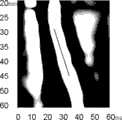
图8为图7中白色线条对应位置的应变随深度和时间的变化图像。Figure 8 is an image of the strain at the position corresponding to the white line in Figure 7 as a function of depth and time.
【具体实施方式】【Detailed ways】
图1示出了一个实施例中弹性测量的超声成像系统,该系统包括探头10、超声成像装置310、控制和处理装置330以及显示装置350。FIG. 1 shows an ultrasound imaging system for elasticity measurement in an embodiment, the system includes a
探头10包括低频振荡驱动装置110以及超声换能器阵列130。The
低频振荡驱动装置110,用于产生振动并形成从体表向组织内部传播的剪切波。The low-frequency
本实施例中,低频振荡驱动装置110为低频振荡器或电机。为通过外力或内力作用使生物组织发生微小形变,通过低频振荡驱动器110中的振动轴111发生低频低幅振动,引起向生物组织中传播的剪切波并诱导其发生微小形变。In this embodiment, the low-frequency
低频振荡驱动装置110中若剪切波的频率太高,则剪切波衰减太低,若频率太低,则衍射效应太强,这一切都不利于剪切波的传播。若低频振荡驱动装置110中剪切波振幅太小,则使得传播深度有限,剪切波振幅太大,也会使得人体有不适感,因此在优选的实施例中,低频振荡驱动装置110所产生的振动频率为10赫兹到1000赫兹,振幅为0.2毫米至2毫米。If the frequency of the shear wave in the low-frequency
超声换能器阵列130,用于向组织发射超声波信号,并接收组织超声回波信号。The
本实施例中,超声换能器阵列130为线阵超声换能器、凸阵超声换能器或相控阵超声换能器中的任意一种。超声换能器阵列130与人或动物的体表接触,以获取到生物组织的二维超声图像。通过超声换能器阵列130实时获得的二维超声图像进行精确定位,根据实际需要辅助和引导探头10进行精确的定位,具体地,二维超声图像中间位置的扫描线所对应的位置即为待检测区域,为实际的临床瞬时弹性成像过程提供了精确定位。In this embodiment, the
超声换能器阵列130与低频振荡驱动装置110集成在一起组成了弹性测量的超声成像系统的探头10,在实际的使用过程中移动探头10可实时获取到生物组织的二维超声图像。The
具体地,如图2和图3所示,超声换能器阵列130的中间位置开设通孔,低频振荡驱动装置110的振动轴111穿过通孔。本实施例中,超声换能器阵列130包含了多个换能器阵无133,且该超声换能器阵列130的中心开设通孔(图未示),该通孔的直径与振动轴111相匹配。振动轴111穿过通孔伸出的长度不能太长,如果振动轴111伸出通孔的长度太长将会使得超声换能器阵列130难以接触到人体或生物体的体表,无法成像,因此振动轴111穿过通孔所伸出的长度优选为0.5~1.5毫米。Specifically, as shown in FIG. 2 and FIG. 3 , a through hole is opened in the middle of the
超声成像装置310,根据所加载的成像参数,用于驱动所述超声换能器阵列130向生物组织发射超声波信号,并接收和处理来自超声换能器阵列130的超声回波信号。The
本实施例中,超声成像装置310用于加载控制和处理装置330提供的发射和接收延迟等成像参数,驱动超声换能器阵列130发射超声波信号,接收和处理超声回波信号并进行波束合成。In this embodiment, the
超声成像装置310经过波束合成后的超声回波信号进入控制和处理装置330,经过该控制和处理装置330的处理得到组织的实时二维超声图像。The ultrasonic echo signal after beamforming by the
具体地,超声成像装置310包括了超声发射模块311、超声接收模块313以及发射接收开关电路315。其中,超声发射模块311用于控制超声换能器阵列130发射超声波信号,超声接收模块313用于控制超声换能器阵列130接收超声回波信号,而发射接收开关电路315用于隔离高压。Specifically, the
控制和处理装置330,用于控制低频振荡驱动装置110和超声成像装置310,处理来自超声成像装置310的超声回波信号得到组织的二维超声图像及弹性信息。The control and
本实施例中,控制和处理装置330还用于对低频振荡驱动装置的振动幅度、频率、时间的控制,提供超声成像的参数控制,并处理来自超声成像装置310的超声回波信号。具体地,控制和处理装置330将根据超声波传播速度、阵元间距以及探测深度等参数进行计算,以控制超声换能器阵列130的开启时间、关闭时间、脉冲宽度以及脉冲重复率等方面。控制和处理装置330为超声成像装置310提供了精确的参数以进行扫描式聚焦。In this embodiment, the control and
在优选的实施例中,控制和处理装置330可以是计算机、单片机、现场可编程门阵列(Field-Programmable Gate Array,简称FPGA)以及ARM处理器中的至少一种。In a preferred embodiment, the control and
具体地,控制和处理装置330包括低频振荡驱动控制单元331、超声成像控制单元333以及信号处理单元335。低频振荡驱动控制单元331用于控制低频振荡驱动装置110;超声成像控制单元333用于为超声成像装置310提供成像参数;信号处理单元335用于对接收的超声回波信号进行成像处理,并计算弹性信息。Specifically, the control and
信号处理单元335对超声回波信号进行滤波、位移估计、应变估计等算法处理,以计算出低频剪切波在生物组织中的传播速度,进而计算出生物组织的弹性信息和重构出二维超声图像。例如,根据生物组织中弹性模量与剪切波传播速度的关系求出该生物组织的弹性模量,进而得到该生物组织的弹性信息,从而结合已有的生物组织、器官结构信息为临床提供更为全面、可靠的病变诊断依据。再如对于肝组织而言,计算出的剪切波传播速度为v,则肝组织弹性模量为E=3ρv2,其中,ρ为肝组织的密度。The
信号处理单元335对超声回波信号的第一次滤波主要是使用带通滤波的方法,其作用是滤除超声回波信号中的低频和高频成分,保留与超声换能器阵列130中心频率及其带宽相适应的超声波信号成分;位移估计常采用时域互相关、自相关或其他的频率处理方法,其目的是为了获取剪切波传播所造成的组织偏移;第二次滤波主要是平滑滤波和匹配滤波,其作用是滤除位移估计中的奇异点和增强与剪切波频率相当的位移成分;应变估计可采用最小二乘法、低通滤波差分法或小波分析等方法,其目的是从生物组织的位移分布得到应变分布,并尽可能减小由于差分(微分)过程中所带来的噪声干扰。The first filtering of the ultrasonic echo signal by the
如图4所示,控制和处理装置330根据超声换能器阵列130中的相邻换能器阵元间距de、标号为n的换能器阵元对应位置的超声扫描线聚焦深度DF、每次发射或接收最边缘的换能器阵元到聚焦点的距离D0、标号为i的换能器阵元到聚焦点的距离以及超声波在生物组织中的传播速度C,对标识为i的超声换能器阵元对应位置的超声扫描线,发射延迟Edelay和接收延迟Rdelay通过以下公式计算得到:As shown in FIG. 4 , the control and
即:Right now:
通过控制和处理装置330对发射延迟和接收延迟的处理,使超声波信号与对应深度相匹配。The ultrasound signal is matched to the corresponding depth by the processing of the transmission delay and the reception delay by the control and processing means 330 .
显示装置350,用于显示组织二维超声图像及弹性信息。The
在超声弹性成像系统进行弹性成像之前,超声换能器阵列130还用于向接触的待测体表发射超声波信号,并接收超声回波信号;控制和处理装置330还用于根据接收到的超声回波信号形成待测体表的实时二维超声图像;探头10用于根据实时二维超声图像进行定位,确定待测体表的待检测区域。Before the ultrasonic elastography system performs elastic imaging, the
本实施例中,在进行超声弹性成像时,首先在使超声换能器阵列130与人或动物体等的体表接触后发射超声波信号,并通过超声换能器阵列130所接收到的超声回波信号形成待测体表的实时二维超声图像,并通过显示装置350显示出来,此时根据待测体表的实时二维超声图像引导探头10在待测体表进行定位,以确定待测体表中的待检测区域。In this embodiment, when ultrasonic elastography is performed, firstly, after the
图5示出了一个实施例中测量生物组织弹性的方法,包括如下步骤:Figure 5 shows a method for measuring the elasticity of biological tissue in one embodiment, including the following steps:
步骤S110,利用生物组织的实时二维超声图像进行定位,确定生物组织待检测区域。Step S110, using the real-time two-dimensional ultrasonic image of the biological tissue for positioning, and determining the region to be detected of the biological tissue.
步骤S130,控制低频振荡驱动装置产生振动并形成从体表向生物组织内部传播的剪切波,诱导生物组织发生微小形变。Step S130, controlling the low-frequency oscillating driving device to vibrate and form a shear wave propagating from the body surface to the interior of the biological tissue, inducing micro-deformation of the biological tissue.
步骤S150,利用振动轴左右各一部分超声换能器阵元,根据控制和处理装置提供的延迟参数和1kHz~10KHz的高脉冲重复频率发射超声波信号并接收超声回波信号,超声回波信号通过波束合成形成沿振动轴中心方向的超声信号序列。Step S150, using a part of the ultrasonic transducer array elements on the left and right sides of the vibration axis to transmit ultrasonic signals and receive ultrasonic echo signals according to the delay parameters provided by the control and processing device and the high pulse repetition frequency of 1 kHz to 10 kHz, and the ultrasonic echo signals pass through the beam Synthesize to form an ultrasonic signal sequence along the center direction of the vibration axis.
本实施例中,所使用的脉冲重复率为一个较高的脉冲重复率。In this embodiment, the pulse repetition rate used is a relatively high pulse repetition rate.
步骤S170,利用弹性成像算法处理和计算超声信号序列得到生物组织待检测区域的弹性信息。Step S170, using an elastography algorithm to process and calculate the ultrasonic signal sequence to obtain elasticity information of the region to be detected in the biological tissue.
在一个具体地实施例中,如图6所示,上述利用弹性成像算法处理和计算超声信号序列得到生物组织待检测区域的弹性信息的具体过程为:In a specific embodiment, as shown in FIG. 6 , the specific process for obtaining the elasticity information of the region to be detected of the biological tissue by using the elastography algorithm to process and calculate the ultrasonic signal sequence is as follows:
步骤S171,对超声信号序列进行滤波。Step S171, filtering the ultrasonic signal sequence.
本实施例中,对超声信号序列所进行的滤波可以滤除超声回波信号中的低频和高频成分。In this embodiment, the filtering performed on the ultrasonic signal sequence can filter out low-frequency and high-frequency components in the ultrasonic echo signal.
步骤S172,根据滤波后的超声信号序列计算由剪切波传播所造成的组织位移。Step S172, calculating tissue displacement caused by shear wave propagation according to the filtered ultrasound signal sequence.
本实施例中,根据超声信号序列采用时域互相关、自相关或其他的频率处理方法进行组织位移估计,得到由剪切波传播所造成的组织位移。In this embodiment, tissue displacement is estimated by using time-domain cross-correlation, auto-correlation or other frequency processing methods according to the ultrasound signal sequence to obtain tissue displacement caused by shear wave propagation.
步骤S173,对组织位移进行平滑滤波和匹配滤波。Step S173, performing smoothing filtering and matching filtering on the tissue displacement.
本实施例中,在得到估计的组织位移后滤除组织位移中的奇异点和增强与剪切波频率相当的位移成分。In this embodiment, after obtaining the estimated tissue displacement, the singular points in the tissue displacement are filtered out and the displacement components corresponding to the frequency of the shear wave are enhanced.
步骤S174,根据组织位移计算组织应变。Step S174, calculating tissue strain according to tissue displacement.
本实施例中,生物组织的应变计算可采用采用最小二乘法、低通滤波差分法或小波分析等方法,其目的是从生物组织的位移分布得到应变分布,并尽可能减小由于差分(微分)过程中所带来的噪声干扰。In this embodiment, methods such as least squares method, low-pass filter difference method, or wavelet analysis can be used to calculate the strain of biological tissue. ) The noise interference caused by the process.
步骤S175,由组织应变计算得到生物组织中剪切波传播速度。Step S175, calculating the propagation velocity of the shear wave in the biological tissue from the tissue strain.
步骤S176,根据生物组织中剪切波传播速度以及经验公式计算得到生物组织的弹性模量。Step S176, calculating the elastic modulus of the biological tissue according to the propagation velocity of the shear wave in the biological tissue and an empirical formula.
步骤S190,显示生物组织待检测区域的弹性信息。Step S190, displaying elasticity information of the area to be detected in the biological tissue.
下面结合一个具体的实施例了详细阐述控制和处理装置330对超声回波信号序列进行计算处理得到组织弹性信息的过程。该实施例中,发射的超声波信号为50赫兹,周期T=300μs,超声波传播速度V=1500m/s,采样频率f=60MHz,在一个周期中超声换能器阵列130采样得到T*F=18000个点。因为实际上超声波的路径中存在入射与反射,因而在回波的一个来回入射深度为T*V/2=22.5cm。实验表明,在回波信号的后续处理中,每一周期内采集到的18000个点的第1000~5000是有用且足够的。采样时间总长为t=0.1s,等价于超声波信号中的t/T=333个周期,因此,取其中的300个周期的超声波信号进行分析处理,即对4000×300的矩阵分析处理。The process of calculating and processing the ultrasonic echo signal sequence by the control and
在信号处理单元335开始互相关算法之前,首先求得做互相关匹配的两份数据,第一份即为上述4000×300的数组,第二份数据舍弃原始数组的第一列数据,取其第2列数据,共4000个点作为第二份数据的第1列,取第一份数据的第3列作为第二份数据的第2列,并以此类推直至取第一份数据的第301列作为第二份数据的第300列,最后得4000×300的数组。Before the
为提高互相关匹配的精确度,需先对要进行互相关匹配的两份数据分别进行带通滤波,然后开始互相关匹配算法。所采用的互相关算法的窗长为100个点,窗间重叠率为90%,步长为10个点。在实际算法中,以第一份数据的第一列作为匹配模板与第二份数据的第一列的滑动块开始匹配运算。模板由200个点组成,滑动块为模板起始点所对应位置的100个点作为初始滑动块,模板与滑动块在同样的起始点位置开始匹配运算,一次匹配运算结束后,滑动块往深度方向滑动1个点,再一次与模板进行匹配,依次不断重复这一过程直至滑动块的末尾点移动至模板的末尾点,得到此次匹配结果的最大值及其所在的位置,插值拟合该点的相对位移后,将结果存入相对位移矩阵。然后将模板及滑动块的初始位置均往深度方向移动10个点,再次进行上述匹配过程直至该列数据点的末尾。至此,以第一份数据的第一列作为匹配模板与以第二份数据的第一列作为滑动块的匹配运算结束。然后开始进行下一个循环,以第一份数据的第二列作为匹配模板与以第二份数据的第二列作为滑动块开始新一轮的匹配运算,如是循环直至两份数据之间的互相关匹配运算完全结束为止,得到一个相对位移矩阵,矩阵大小为380×300。In order to improve the accuracy of cross-correlation matching, it is necessary to perform band-pass filtering on the two sets of data to be cross-correlation matching first, and then start the cross-correlation matching algorithm. The window length of the cross-correlation algorithm used is 100 points, the overlap rate between windows is 90%, and the step size is 10 points. In the actual algorithm, the first column of the first data is used as the matching template to start the matching operation with the slider of the first column of the second data. The template is composed of 200 points, and the slider is 100 points corresponding to the starting point of the template as the initial slider. The template and the slider start matching operation at the same starting point position. After a matching operation is completed, the slider moves to the depth direction. Slide 1 point, match with the template again, repeat this process in turn until the end point of the slider moves to the end point of the template, get the maximum value of the matching result and its position, and interpolate to fit the point After the relative displacement of , store the result in the relative displacement matrix. Then move the initial positions of the template and the
为提高位移估计的精确度,需要对互相关运算结果进行平滑滤波处理以滤去奇异点,在此之后,根据滤波后的相对位移数组可通过逐列叠加绝对位移矩阵。得到绝对位移矩阵后,需要增强位移信号,因此通过匹配滤波器来达到增强效果。In order to improve the accuracy of displacement estimation, it is necessary to smooth and filter the results of cross-correlation operations to filter out singular points. After that, according to the filtered relative displacement array, the absolute displacement matrix can be superimposed column by column. After obtaining the absolute displacement matrix, the displacement signal needs to be enhanced, so the enhanced effect is achieved through a matched filter.
由位移数组入手求取应变,首先对绝对位移做一个基于最小二乘法的5点应变估计,5点最小二乘直线拟合所得到的结果为点斜式,其中直线斜率即为中心点应变,把斜率存入一大小为375×300的应变矩阵中。Starting from the displacement array to calculate the strain, firstly make a 5-point strain estimation based on the least squares method for the absolute displacement, and the result obtained by the 5-point least squares straight line fitting is a point-slope formula, where the slope of the straight line is the central point strain, Store the slopes in a strain matrix of size 375x300.
所感兴趣的区域深度为2.5cm-4.5cm,即对应于矩阵中每一列的第100-260点,在此段区域内找到最大最小值,然后进行最小二乘直线拟合求得剪切波传播速度Vs,再根据经验公式可求得弹性模量,公式为:The depth of the area of interest is 2.5cm-4.5cm, which corresponds to the 100-260th point of each column in the matrix. Find the maximum and minimum values in this area, and then perform least squares straight line fitting to obtain the shear wave propagation Velocity Vs, and then the elastic modulus can be obtained according to the empirical formula, the formula is:
E=3ρVs2其中,ρ为组织密度。E=3ρVs2 where ρ is the tissue density.
图7示出了上述超声弹性成像系统实际使用过程中肝脏的二维超声图像,其中,白色线条表示待检测的肝脏区域,白色方框表示超声换能器阵列130聚焦位置。FIG. 7 shows a two-dimensional ultrasound image of the liver during the actual use of the above-mentioned ultrasound elastography system, where the white lines indicate the liver area to be detected, and the white squares indicate the focus position of the
图8示出了图7的白色线条对应位置的应变随时间的变化图像,其中,纵坐标表示肝脏深度,横坐标表示时间,黑色线条的斜率代表剪切波在肝组织中的传播速度。Fig. 8 shows the image of the strain over time at the position corresponding to the white line in Fig. 7, where the ordinate represents the depth of the liver, the abscissa represents time, and the slope of the black line represents the propagation speed of the shear wave in the liver tissue.
上述弹性测量的超声成像系统及测量生物组织弹性的方法,能同时获得组织二维超声图像和组织弹性信息,提高临床诊断准确性;探头可在二维超声图像引导下实现精确定位,低频振荡驱动装置与超声换能器阵列是相对独立的,超声换能器阵列并不会随着低频振荡驱动装置发生运动,即便超声换能器阵列由于低频振荡驱动装置而发生了微小运动,在进行应变估计时的运算也会抵消超声换能器阵列微小运动所造成的位移,因此无需要考虑位移补偿,提高了组织弹性测量的便捷性和精确性,降低了处理的难度。The above-mentioned ultrasonic imaging system for elasticity measurement and the method for measuring the elasticity of biological tissue can obtain tissue two-dimensional ultrasonic images and tissue elasticity information at the same time, and improve the accuracy of clinical diagnosis; The device and the ultrasonic transducer array are relatively independent, and the ultrasonic transducer array does not move with the low-frequency oscillation drive device. Even if the ultrasonic transducer array has a small movement due to the low-frequency oscillation drive device, the strain estimation The calculation of time will also offset the displacement caused by the micro-motion of the ultrasonic transducer array, so there is no need to consider displacement compensation, which improves the convenience and accuracy of tissue elasticity measurement and reduces the difficulty of processing.
上述弹性测量的超声成像系统及测量生物组织弹性的方法,由生物组织的超声二维图像可以直观地得到生物组织、器官详细的结构信息,在实际的瞬时弹性成像检测过程中还能辅助和引导探头及成像检测区域的精确定位,进而结合弹性信息为超声成像的临床诊断提供更加全面的依据,从而提高诊断的准确性和前瞻性。The above-mentioned ultrasonic imaging system for elastic measurement and the method for measuring the elasticity of biological tissue can intuitively obtain detailed structural information of biological tissue and organs from the ultrasonic two-dimensional image of biological tissue, and can also assist and guide in the actual instantaneous elastic imaging detection process The precise positioning of the probe and imaging detection area, combined with elastic information, provides a more comprehensive basis for the clinical diagnosis of ultrasound imaging, thereby improving the accuracy and prospective of diagnosis.
以上所述实施例仅表达了本发明的几种实施方式,其描述较为具体和详细,但并不能因此而理解为对本发明专利范围的限制。应当指出的是,对于本领域的普通技术人员来说,在不脱离本发明构思的前提下,还可以做出若干变形和改进,这些都属于本发明的保护范围。因此,本发明专利的保护范围应以所附权利要求为准。The above-mentioned embodiments only express several implementation modes of the present invention, and the description thereof is relatively specific and detailed, but should not be construed as limiting the patent scope of the present invention. It should be pointed out that those skilled in the art can make several modifications and improvements without departing from the concept of the present invention, and these all belong to the protection scope of the present invention. Therefore, the protection scope of the patent for the present invention should be based on the appended claims.
Claims (12)
Priority Applications (2)
| Application Number | Priority Date | Filing Date | Title |
|---|---|---|---|
| CN201110222813.1ACN102283679B (en) | 2011-08-04 | 2011-08-04 | Ultrasonic imaging system for elasticity measurement and method for measuring elasticity of biological tissue |
| PCT/CN2012/079668WO2013017105A1 (en) | 2011-08-04 | 2012-08-03 | Ultrasonic imaging system and method for measuring elasticity of biological tissues |
Applications Claiming Priority (1)
| Application Number | Priority Date | Filing Date | Title |
|---|---|---|---|
| CN201110222813.1ACN102283679B (en) | 2011-08-04 | 2011-08-04 | Ultrasonic imaging system for elasticity measurement and method for measuring elasticity of biological tissue |
Publications (2)
| Publication Number | Publication Date |
|---|---|
| CN102283679A CN102283679A (en) | 2011-12-21 |
| CN102283679Btrue CN102283679B (en) | 2014-05-21 |
Family
ID=45330633
Family Applications (1)
| Application Number | Title | Priority Date | Filing Date |
|---|---|---|---|
| CN201110222813.1AActiveCN102283679B (en) | 2011-08-04 | 2011-08-04 | Ultrasonic imaging system for elasticity measurement and method for measuring elasticity of biological tissue |
Country Status (2)
| Country | Link |
|---|---|
| CN (1) | CN102283679B (en) |
| WO (1) | WO2013017105A1 (en) |
Families Citing this family (85)
| Publication number | Priority date | Publication date | Assignee | Title |
|---|---|---|---|---|
| KR101906838B1 (en) | 2010-10-13 | 2018-10-11 | 마우이 이미징, 인코포레이티드 | Concave ultrasound transducers and 3d arrays |
| CN102283679B (en)* | 2011-08-04 | 2014-05-21 | 中国科学院深圳先进技术研究院 | Ultrasonic imaging system for elasticity measurement and method for measuring elasticity of biological tissue |
| CN102599938B (en)* | 2012-02-01 | 2015-11-25 | 无锡海斯凯尔医学技术有限公司 | A kind of combined probe for elasticity measurement |
| JP6438769B2 (en) | 2012-02-21 | 2018-12-19 | マウイ イマギング,インコーポレーテッド | Determination of material hardness using multiple aperture ultrasound. |
| WO2013148673A1 (en) | 2012-03-26 | 2013-10-03 | Maui Imaging, Inc. | Systems and methods for improving ultrasound image quality by applying weighting factors |
| WO2013153857A1 (en)* | 2012-04-13 | 2013-10-17 | 日立アロカメディカル株式会社 | Ultrasonic diagnostic device and locus display method |
| JP6270843B2 (en) | 2012-08-10 | 2018-01-31 | マウイ イマギング,インコーポレーテッド | Calibration of multiple aperture ultrasonic probes |
| US20140064513A1 (en) | 2012-09-06 | 2014-03-06 | MUSIC Group IP Ltd. | System and method for remotely controlling audio equipment |
| CN103800038B (en)* | 2012-11-12 | 2016-09-21 | 通用电气公司 | The system improved and device are for the mechanical property determining destination organization |
| CN103054552B (en)* | 2012-12-24 | 2014-12-10 | 深圳先进技术研究院 | Method and system for measuring biological tissue viscoelasticity |
| DE102014003105A1 (en)* | 2013-03-15 | 2014-09-18 | Siemens Medical Solutions Usa, Inc. | FAT RELATED TO ULTRASOUND WITH SHEAR WAVE SPREAD |
| US10743814B2 (en) | 2013-03-15 | 2020-08-18 | Siemens Medical Solutions Usa, Inc. | Fat fraction estimation using ultrasound with shear wave propagation |
| CN103431874B (en)* | 2013-09-06 | 2015-06-03 | 中国科学院深圳先进技术研究院 | Method and system for estimating acoustic radiation force pulse imaging |
| US9883848B2 (en) | 2013-09-13 | 2018-02-06 | Maui Imaging, Inc. | Ultrasound imaging using apparent point-source transmit transducer |
| WO2015040230A1 (en)* | 2013-09-23 | 2015-03-26 | Koninklijke Philips N.V. | Medical apparatus for treating cells with vibrations |
| CN104644209B (en)* | 2013-11-21 | 2017-06-20 | 通用电气公司 | Ultrasound Instrument and the vibrating device being applied thereon |
| CN103908304A (en)* | 2014-03-14 | 2014-07-09 | 中瑞科技(常州)有限公司 | Ultrasonic elastography system |
| CN105266843B (en)* | 2014-07-23 | 2018-06-08 | 通用电气公司 | The method that ultrasonic system and use ultrasonic system obtain the two-dimension elastic figure of destination organization |
| CN106794007B (en) | 2014-08-18 | 2021-03-09 | 毛伊图像公司 | Network-based ultrasound imaging system |
| CN106999162B (en)* | 2014-12-08 | 2020-05-19 | 株式会社日立制作所 | Ultrasonic diagnostic apparatus and elasticity evaluation method |
| US11109832B2 (en)* | 2015-01-29 | 2021-09-07 | Koninklijke Philips N.V. | Evaluation of cardiac infarction by real time ultrasonic strain imaging |
| KR102681141B1 (en) | 2015-03-30 | 2024-07-02 | 마우이 이미징, 인코포레이티드 | Ultrasonic imaging systems and methods for detecting object motion |
| KR101649725B1 (en) | 2015-05-14 | 2016-08-19 | 삼성전자주식회사 | Method and ultrasonic diagnotic apparatus for displaying elasticity image |
| CN104856729B (en)* | 2015-05-25 | 2018-07-31 | 无锡海斯凯尔医学技术有限公司 | The method of controlling operation thereof and elastomeric check equipment of elastomeric check equipment |
| CN113812979B (en)* | 2015-10-08 | 2024-09-13 | 梅约医学教育与研究基金会 | System and method for ultrasound elastography using continuous transducer vibration |
| CN105245766A (en)* | 2015-11-05 | 2016-01-13 | 龚万新 | Auxiliary optical vibration imaging system |
| CN105395217A (en)* | 2015-11-10 | 2016-03-16 | 中国科学院声学研究所 | probe |
| CN108778530B (en) | 2016-01-27 | 2021-07-27 | 毛伊图像公司 | Ultrasound imaging with sparse array detectors |
| CN105559830B (en)* | 2016-02-04 | 2019-02-01 | 汕头市超声仪器研究所有限公司 | It is a kind of to load code-excited ultrasonic imaging method |
| CN107095692B (en)* | 2016-02-19 | 2024-02-09 | 乐普(北京)医疗器械股份有限公司 | Ultrasonic imaging system, ultrasonic imaging method and one-dimensional displacement scanning method |
| US10675007B2 (en) | 2016-04-19 | 2020-06-09 | Siemens Medical Solutions Usa, Inc. | Frequency compounding in elasticity imaging |
| CN105748106B (en)* | 2016-04-22 | 2018-07-31 | 毛军卫 | Ultrasonic probe and ultrasonic detection equipment with the ultrasonic probe |
| CN107928703A (en)* | 2016-10-12 | 2018-04-20 | 甘肃农业大学 | A kind of biological information imaging device and method |
| US20180140279A1 (en)* | 2016-11-22 | 2018-05-24 | General Electric Company | Method and system for enhanced detection and visualization of a surgical needle in ultrasound data by performing shear wave elasticity imaging |
| CN106805997B (en)* | 2016-12-26 | 2020-08-07 | 乐普(北京)医疗器械股份有限公司 | Elastic imaging method and device |
| CN106618635B (en)* | 2017-01-12 | 2019-11-08 | 清华大学 | Shear wave elastography method and device |
| US11553901B2 (en) | 2017-04-06 | 2023-01-17 | Siemens Medical Solutions Usa, Inc. | Liver disease activity estimation with ultrasound medical imaging |
| US11523774B2 (en) | 2017-04-06 | 2022-12-13 | Siemens Medical Solutions Usa, Inc. | Tissue property estimation with ultrasound medical imaging |
| CN114360727A (en)* | 2017-04-21 | 2022-04-15 | 深圳迈瑞生物医疗电子股份有限公司 | Ultrasonic elastography device and elastography result evaluation method |
| CN107440740B (en)* | 2017-07-21 | 2021-06-25 | 无锡海斯凯尔医学技术有限公司 | Method and device for determining viscoelasticity of medium |
| JP6855347B2 (en)* | 2017-07-27 | 2021-04-07 | ゼネラル・エレクトリック・カンパニイ | Ultrasonic diagnostic equipment and its control program |
| TWI743411B (en)* | 2017-11-08 | 2021-10-21 | 美商富士膠片索諾聲公司 | Ultrasound system with high frequency detail |
| CN108065964B (en)* | 2018-01-16 | 2021-04-20 | 中国科学院苏州生物医学工程技术研究所 | Ultrasonic imaging method, device and equipment and ultrasonic imaging probe |
| CN108095766A (en)* | 2018-01-18 | 2018-06-01 | 北京索瑞特医学技术有限公司 | Combined probe and measuring system |
| CN108095765A (en)* | 2018-01-18 | 2018-06-01 | 北京索瑞特医学技术有限公司 | Combined probe and measuring system |
| CN108095763A (en)* | 2018-01-18 | 2018-06-01 | 北京索瑞特医学技术有限公司 | Combined probe and measuring system |
| CN108095764B (en)* | 2018-01-18 | 2024-05-03 | 北京索瑞特医学技术有限公司 | Composite probe and measuring system |
| CN108095762A (en)* | 2018-01-18 | 2018-06-01 | 北京索瑞特医学技术有限公司 | Combined probe and measuring system |
| FR3078484A1 (en)* | 2018-03-02 | 2019-09-06 | Echosens | METHOD FOR MEASURING A GUIDED ULTRASONIC ATTENUATION PARAMETER BY HARMONIC ELASTOGRAPHY, PROBE AND DEVICE FOR IMPLEMENTING THE METHOD |
| WO2019196033A1 (en) | 2018-04-11 | 2019-10-17 | 深圳迈瑞生物医疗电子股份有限公司 | Ultrasound elastography method and system |
| CN114848011B (en)* | 2018-04-13 | 2025-06-17 | 深圳迈瑞生物医疗电子股份有限公司 | Ultrasonic imaging method and ultrasonic imaging device |
| CN110536645B (en)* | 2018-04-28 | 2021-10-08 | 深圳迈瑞生物医疗电子股份有限公司 | A kind of ultrasonic instantaneous elasticity measurement equipment and method |
| CN110292399B (en)* | 2018-05-04 | 2022-03-08 | 深圳迈瑞生物医疗电子股份有限公司 | Method and system for measuring shear wave elasticity |
| CN109372497B (en)* | 2018-08-20 | 2022-03-29 | 中国石油天然气集团有限公司 | Ultrasonic imaging dynamic equalization processing method |
| CN109199381B (en)* | 2018-09-11 | 2021-11-02 | 合肥工业大学 | A holographic microwave elastography system and its imaging method |
| CN109259801B (en)* | 2018-09-12 | 2021-05-14 | 深圳开立生物医疗科技股份有限公司 | Shear wave elastic imaging method and device |
| WO2020077598A1 (en)* | 2018-10-18 | 2020-04-23 | 深圳迈瑞生物医疗电子股份有限公司 | Ultrasound elasticity detection method and system |
| CN110292395B (en)* | 2018-12-24 | 2021-08-17 | 深圳迈瑞生物医疗电子股份有限公司 | Ultrasonic imaging method and apparatus |
| EP3693756A1 (en)* | 2019-02-07 | 2020-08-12 | SuperSonic Imagine | An ultrasound system |
| CN111743570A (en)* | 2019-03-28 | 2020-10-09 | 无锡声美达医学技术有限公司 | Method and device for detecting ultrasonic measurement depth of ultrasonic elastic measuring instrument with image guide function |
| CN110146594A (en)* | 2019-06-06 | 2019-08-20 | 河海大学 | A kind of device and measuring method for continuously measuring cement setting and hardening rate |
| CN110301939A (en)* | 2019-07-15 | 2019-10-08 | 无锡海斯凯尔医学技术有限公司 | Imaging of tissue and parameter detecting system |
| CN110301938A (en)* | 2019-07-15 | 2019-10-08 | 无锡海斯凯尔医学技术有限公司 | Probe and tissue elasticity detection system |
| JP7672207B2 (en)* | 2019-07-26 | 2025-05-07 | エコセンス | SYSTEMS AND ASSOCIATED METHODS FOR CHARACTERIZING TISSUES - Patent application |
| CN120203627A (en)* | 2019-08-14 | 2025-06-27 | 深圳迈瑞生物医疗电子股份有限公司 | Shear wave elastic imaging method, ultrasonic imaging system and computer readable storage medium |
| CN110710988B (en)* | 2019-09-23 | 2023-03-17 | 无锡海斯凯尔医学技术有限公司 | Detection mode control circuit |
| CN114287968B (en)* | 2019-09-27 | 2024-11-29 | 深圳迈瑞生物医疗电子股份有限公司 | Elastography method, elastography system and computer-readable storage medium |
| CN110811689B (en)* | 2019-10-31 | 2020-11-27 | 汕头市超声仪器研究所股份有限公司 | A First-Order Estimation Method of Shear Wave Velocity |
| CN114340506B (en)* | 2019-12-25 | 2024-04-02 | 深圳迈瑞生物医疗电子股份有限公司 | Ultrasonic viscoelasticity measurement method, device and storage medium |
| CN113520454A (en)* | 2020-04-21 | 2021-10-22 | 深圳迈瑞生物医疗电子股份有限公司 | Ultrasonic instantaneous elasticity detection device, probe and method |
| CN111772677B (en)* | 2020-07-07 | 2023-06-13 | 意领科技有限公司 | Dimensional biological tissue elasticity detection method, detection system and storage medium |
| CN112842397A (en)* | 2020-12-30 | 2021-05-28 | 居天科技(深圳)有限公司 | Face filling ultrasonic detector |
| CN113081041B (en)* | 2021-04-06 | 2024-02-13 | 无锡海斯凯尔医学技术有限公司 | Control method, device and system of composite equipment and storage medium |
| CN113081038B (en)* | 2021-04-06 | 2024-02-13 | 无锡海斯凯尔医学技术有限公司 | Elastography method, elastography device, electronic equipment and storage medium |
| CN112998751A (en)* | 2021-04-06 | 2021-06-22 | 无锡海斯凯尔医学技术有限公司 | Tissue elasticity detection imaging method and equipment |
| CN113397600A (en)* | 2021-06-18 | 2021-09-17 | 复旦大学 | Hepatic fibrosis assessment method based on ultrasonic radio frequency signal elastic reconstruction |
| CN114224382B (en)* | 2021-12-17 | 2023-09-15 | 重庆医科大学 | Viscoelasticity measuring method and system thereof |
| WO2023116927A1 (en)* | 2021-12-24 | 2023-06-29 | 深圳市影越医疗科技有限公司 | Phonophoresis structure, elasticity measurement apparatus, probe, system, and method |
| CN114305493B (en)* | 2021-12-31 | 2025-04-25 | 深圳市影越医疗科技有限公司 | Elasticity detection probe, elasticity detection device and method |
| CN114287964B (en)* | 2021-12-31 | 2025-09-30 | 深圳市影越医疗科技有限公司 | Ultrasonic probe replaceable part, ultrasonic probe and detection method thereof |
| CN114601496B (en)* | 2022-04-08 | 2025-01-03 | 南京大学 | A three-dimensional ultrasonic shear wave elastic imaging method based on linear array |
| CN114748095A (en)* | 2022-04-12 | 2022-07-15 | 深圳欢影医疗科技有限公司 | Multi-mode ultrasonic elastography method and system thereof |
| CN114767161B (en)* | 2022-06-20 | 2022-09-23 | 深圳市影越医疗科技有限公司 | Elasticity detection device, method and system |
| CN115153638B (en)* | 2022-07-25 | 2025-07-01 | 重庆三峡医药高等专科学校 | A method for testing facial elastic modulus |
| CN116671962A (en)* | 2023-05-30 | 2023-09-01 | 无锡海斯凯尔医学技术有限公司 | Method, device and storage medium for determining tissue operating parameters based on detection device |
Citations (2)
| Publication number | Priority date | Publication date | Assignee | Title |
|---|---|---|---|---|
| CN101474083A (en)* | 2009-01-15 | 2009-07-08 | 西安交通大学 | System and method for super-resolution imaging and multi-parameter detection of vascular mechanical characteristic |
| CN102078205A (en)* | 2011-03-04 | 2011-06-01 | 深圳市一体医疗科技股份有限公司 | Displacement estimating method for measuring elasticity of viscoelastic medium and application method |
Family Cites Families (7)
| Publication number | Priority date | Publication date | Assignee | Title |
|---|---|---|---|---|
| EP1782094A2 (en)* | 2004-07-23 | 2007-05-09 | ANGELSEN, Bjorn A. J. | Ultrasound imaging using non-linear manipulation of forward propagation properties of a pulse |
| FR2889659B1 (en)* | 2005-08-12 | 2007-10-12 | Echosens Sa | IMAGEUR SYSTEM OF A HUMAN OR ANIMAL ORGAN PERMITTING THE MEASUREMENT OF THE ELASTICITY OF SAID ORGAN |
| KR101411099B1 (en)* | 2006-10-25 | 2014-06-27 | 수퍼 소닉 이매진 | Method for generating mechanical waves by creating an interfacial acoustic radiation force |
| WO2011004661A1 (en)* | 2009-07-07 | 2011-01-13 | 株式会社 日立メディコ | Ultrasonic diagnosis apparatus and ultrasonic measurement method |
| US9161736B2 (en)* | 2009-09-10 | 2015-10-20 | Hitachi Medical Corporation | Ultrasonic diagnostic apparatus and elasticity image display method |
| JP4712130B2 (en)* | 2011-01-07 | 2011-06-29 | 株式会社日立メディコ | Ultrasonic diagnostic equipment |
| CN102283679B (en)* | 2011-08-04 | 2014-05-21 | 中国科学院深圳先进技术研究院 | Ultrasonic imaging system for elasticity measurement and method for measuring elasticity of biological tissue |
- 2011
- 2011-08-04CNCN201110222813.1Apatent/CN102283679B/enactiveActive
- 2012
- 2012-08-03WOPCT/CN2012/079668patent/WO2013017105A1/enactiveApplication Filing
Patent Citations (2)
| Publication number | Priority date | Publication date | Assignee | Title |
|---|---|---|---|---|
| CN101474083A (en)* | 2009-01-15 | 2009-07-08 | 西安交通大学 | System and method for super-resolution imaging and multi-parameter detection of vascular mechanical characteristic |
| CN102078205A (en)* | 2011-03-04 | 2011-06-01 | 深圳市一体医疗科技股份有限公司 | Displacement estimating method for measuring elasticity of viscoelastic medium and application method |
Non-Patent Citations (1)
| Title |
|---|
| JP特表2010-507428A 2010.03.11 |
Also Published As
| Publication number | Publication date |
|---|---|
| CN102283679A (en) | 2011-12-21 |
| WO2013017105A1 (en) | 2013-02-07 |
Similar Documents
| Publication | Publication Date | Title |
|---|---|---|
| CN102283679B (en) | Ultrasonic imaging system for elasticity measurement and method for measuring elasticity of biological tissue | |
| US12343210B2 (en) | Determining material stiffness using multiple aperture ultrasound | |
| KR101411210B1 (en) | Method and device for measuring a mean value of visco-elasticity of a region of interest | |
| EP2881041B1 (en) | Apparatus and method for ultrasonic diagnosis | |
| JP3723663B2 (en) | Ultrasonic diagnostic equipment | |
| EP2453800B1 (en) | Spatially-fine shear wave dispersion ultrasound vibrometry sampling | |
| US11439367B2 (en) | Hybrid elastography Method, probe and device for hybrid elastography | |
| EP3040033A1 (en) | Diagnostic ultrasound apparatus and elasticity evaluation method | |
| CN106999162A (en) | Diagnostic ultrasound equipment and photoelastic evaluation method | |
| CN109717904B (en) | Elastography system | |
| CN107550458A (en) | The more characteristic imaging methods of biological tissue based on acoustoelectric effect and acoustic radiation force | |
| KR20140086626A (en) | Method for measuring the displacement of shear wave and mechanical parameters in tissue by using shear wave and the system comprising the same | |
| WO2021212578A1 (en) | Viscoelasticity measuring method, elasticity measuring method and ultrasonic measuring system | |
| CN109875608B (en) | Elastography method | |
| CN112294365A (en) | System and associated method for characterizing tissue | |
| CN106232016B (en) | Ultrasonic diagnostic device | |
| CN113520454A (en) | Ultrasonic instantaneous elasticity detection device, probe and method | |
| JP2006523485A (en) | Heart wall strain imaging | |
| CN209899434U (en) | Elastography system | |
| JP2005324072A (en) | Ultrasonic diagnostic equipment | |
| RU2794039C2 (en) | Hybrid elastography method, probe and device for hybrid elastography | |
| Jiao et al. | A shear wave endoscopic elasticity imaging approach with micro focused piezoelectric transducer | |
| JP2024504635A (en) | System and method for non-invasive determination of bladder overactivity using ultrasonic vibrometry | |
| HK40038679A (en) | System for characterizing tissue and associated method | |
| Deshmukh | REAL-TIME ELASTOGRAPHY SYSTEMS |
Legal Events
| Date | Code | Title | Description |
|---|---|---|---|
| C06 | Publication | ||
| PB01 | Publication | ||
| C10 | Entry into substantive examination | ||
| SE01 | Entry into force of request for substantive examination | ||
| C14 | Grant of patent or utility model | ||
| GR01 | Patent grant | ||
| C41 | Transfer of patent application or patent right or utility model | ||
| TR01 | Transfer of patent right | Effective date of registration:20160127 Address after:102200, Beijing Changping District science and Technology Park, super Road, No. 37 Patentee after:Lepu (Beijing) Medical Equipment Co.,Ltd. Address before:1068 No. 518055 Guangdong city in Shenzhen Province, Nanshan District City Xili University School Avenue Patentee before:Shenzhen Institutes of Advanced Technology, Chinese Academy of Science |