CN102278628A - lighting device - Google Patents
lighting deviceDownload PDFInfo
- Publication number
- CN102278628A CN102278628ACN2011101504115ACN201110150411ACN102278628ACN 102278628 ACN102278628 ACN 102278628ACN 2011101504115 ACN2011101504115 ACN 2011101504115ACN 201110150411 ACN201110150411 ACN 201110150411ACN 102278628 ACN102278628 ACN 102278628A
- Authority
- CN
- China
- Prior art keywords
- cover member
- light source
- source unit
- light
- end plate
- Prior art date
- Legal status (The legal status is an assumption and is not a legal conclusion. Google has not performed a legal analysis and makes no representation as to the accuracy of the status listed.)
- Granted
Links
Images


Classifications
- F—MECHANICAL ENGINEERING; LIGHTING; HEATING; WEAPONS; BLASTING
- F21—LIGHTING
- F21V—FUNCTIONAL FEATURES OR DETAILS OF LIGHTING DEVICES OR SYSTEMS THEREOF; STRUCTURAL COMBINATIONS OF LIGHTING DEVICES WITH OTHER ARTICLES, NOT OTHERWISE PROVIDED FOR
- F21V15/00—Protecting lighting devices from damage
- F21V15/01—Housings, e.g. material or assembling of housing parts
- F21V15/015—Devices for covering joints between adjacent lighting devices; End coverings
- F—MECHANICAL ENGINEERING; LIGHTING; HEATING; WEAPONS; BLASTING
- F21—LIGHTING
- F21K—NON-ELECTRIC LIGHT SOURCES USING LUMINESCENCE; LIGHT SOURCES USING ELECTROCHEMILUMINESCENCE; LIGHT SOURCES USING CHARGES OF COMBUSTIBLE MATERIAL; LIGHT SOURCES USING SEMICONDUCTOR DEVICES AS LIGHT-GENERATING ELEMENTS; LIGHT SOURCES NOT OTHERWISE PROVIDED FOR
- F21K9/00—Light sources using semiconductor devices as light-generating elements, e.g. using light-emitting diodes [LED] or lasers
- F21K9/20—Light sources comprising attachment means
- F21K9/27—Retrofit light sources for lighting devices with two fittings for each light source, e.g. for substitution of fluorescent tubes
- F21K9/272—Details of end parts, i.e. the parts that connect the light source to a fitting; Arrangement of components within end parts
- F—MECHANICAL ENGINEERING; LIGHTING; HEATING; WEAPONS; BLASTING
- F21—LIGHTING
- F21S—NON-PORTABLE LIGHTING DEVICES; SYSTEMS THEREOF; VEHICLE LIGHTING DEVICES SPECIALLY ADAPTED FOR VEHICLE EXTERIORS
- F21S2/00—Systems of lighting devices, not provided for in main groups F21S4/00 - F21S10/00 or F21S19/00, e.g. of modular construction
- F—MECHANICAL ENGINEERING; LIGHTING; HEATING; WEAPONS; BLASTING
- F21—LIGHTING
- F21S—NON-PORTABLE LIGHTING DEVICES; SYSTEMS THEREOF; VEHICLE LIGHTING DEVICES SPECIALLY ADAPTED FOR VEHICLE EXTERIORS
- F21S4/00—Lighting devices or systems using a string or strip of light sources
- F21S4/20—Lighting devices or systems using a string or strip of light sources with light sources held by or within elongate supports
- F21S4/28—Lighting devices or systems using a string or strip of light sources with light sources held by or within elongate supports rigid, e.g. LED bars
- F—MECHANICAL ENGINEERING; LIGHTING; HEATING; WEAPONS; BLASTING
- F21—LIGHTING
- F21V—FUNCTIONAL FEATURES OR DETAILS OF LIGHTING DEVICES OR SYSTEMS THEREOF; STRUCTURAL COMBINATIONS OF LIGHTING DEVICES WITH OTHER ARTICLES, NOT OTHERWISE PROVIDED FOR
- F21V3/00—Globes; Bowls; Cover glasses
- F21V3/04—Globes; Bowls; Cover glasses characterised by materials, surface treatments or coatings
- F21V3/06—Globes; Bowls; Cover glasses characterised by materials, surface treatments or coatings characterised by the material
- F21V3/062—Globes; Bowls; Cover glasses characterised by materials, surface treatments or coatings characterised by the material the material being plastics
- F21V3/0625—Globes; Bowls; Cover glasses characterised by materials, surface treatments or coatings characterised by the material the material being plastics the material diffusing light, e.g. translucent plastics
- F—MECHANICAL ENGINEERING; LIGHTING; HEATING; WEAPONS; BLASTING
- F21—LIGHTING
- F21V—FUNCTIONAL FEATURES OR DETAILS OF LIGHTING DEVICES OR SYSTEMS THEREOF; STRUCTURAL COMBINATIONS OF LIGHTING DEVICES WITH OTHER ARTICLES, NOT OTHERWISE PROVIDED FOR
- F21V15/00—Protecting lighting devices from damage
- F21V15/04—Resilient mountings, e.g. shock absorbers
- F—MECHANICAL ENGINEERING; LIGHTING; HEATING; WEAPONS; BLASTING
- F21—LIGHTING
- F21V—FUNCTIONAL FEATURES OR DETAILS OF LIGHTING DEVICES OR SYSTEMS THEREOF; STRUCTURAL COMBINATIONS OF LIGHTING DEVICES WITH OTHER ARTICLES, NOT OTHERWISE PROVIDED FOR
- F21V29/00—Protecting lighting devices from thermal damage; Cooling or heating arrangements specially adapted for lighting devices or systems
- F21V29/85—Protecting lighting devices from thermal damage; Cooling or heating arrangements specially adapted for lighting devices or systems characterised by the material
- F21V29/89—Metals
- F—MECHANICAL ENGINEERING; LIGHTING; HEATING; WEAPONS; BLASTING
- F21—LIGHTING
- F21V—FUNCTIONAL FEATURES OR DETAILS OF LIGHTING DEVICES OR SYSTEMS THEREOF; STRUCTURAL COMBINATIONS OF LIGHTING DEVICES WITH OTHER ARTICLES, NOT OTHERWISE PROVIDED FOR
- F21V9/00—Elements for modifying spectral properties, polarisation or intensity of the light emitted, e.g. filters
- F21V9/08—Elements for modifying spectral properties, polarisation or intensity of the light emitted, e.g. filters for producing coloured light, e.g. monochromatic; for reducing intensity of light
- F—MECHANICAL ENGINEERING; LIGHTING; HEATING; WEAPONS; BLASTING
- F21—LIGHTING
- F21W—INDEXING SCHEME ASSOCIATED WITH SUBCLASSES F21K, F21L, F21S and F21V, RELATING TO USES OR APPLICATIONS OF LIGHTING DEVICES OR SYSTEMS
- F21W2131/00—Use or application of lighting devices or systems not provided for in codes F21W2102/00-F21W2121/00
- F21W2131/30—Lighting for domestic or personal use
- F21W2131/305—Lighting for domestic or personal use for refrigerators
- F—MECHANICAL ENGINEERING; LIGHTING; HEATING; WEAPONS; BLASTING
- F21—LIGHTING
- F21W—INDEXING SCHEME ASSOCIATED WITH SUBCLASSES F21K, F21L, F21S and F21V, RELATING TO USES OR APPLICATIONS OF LIGHTING DEVICES OR SYSTEMS
- F21W2131/00—Use or application of lighting devices or systems not provided for in codes F21W2102/00-F21W2121/00
- F21W2131/40—Lighting for industrial, commercial, recreational or military use
- F21W2131/405—Lighting for industrial, commercial, recreational or military use for shop-windows or displays
- F—MECHANICAL ENGINEERING; LIGHTING; HEATING; WEAPONS; BLASTING
- F21—LIGHTING
- F21Y—INDEXING SCHEME ASSOCIATED WITH SUBCLASSES F21K, F21L, F21S and F21V, RELATING TO THE FORM OR THE KIND OF THE LIGHT SOURCES OR OF THE COLOUR OF THE LIGHT EMITTED
- F21Y2103/00—Elongate light sources, e.g. fluorescent tubes
- F21Y2103/10—Elongate light sources, e.g. fluorescent tubes comprising a linear array of point-like light-generating elements
- F—MECHANICAL ENGINEERING; LIGHTING; HEATING; WEAPONS; BLASTING
- F21—LIGHTING
- F21Y—INDEXING SCHEME ASSOCIATED WITH SUBCLASSES F21K, F21L, F21S and F21V, RELATING TO THE FORM OR THE KIND OF THE LIGHT SOURCES OR OF THE COLOUR OF THE LIGHT EMITTED
- F21Y2115/00—Light-generating elements of semiconductor light sources
- F21Y2115/10—Light-emitting diodes [LED]
- F—MECHANICAL ENGINEERING; LIGHTING; HEATING; WEAPONS; BLASTING
- F21—LIGHTING
- F21Y—INDEXING SCHEME ASSOCIATED WITH SUBCLASSES F21K, F21L, F21S and F21V, RELATING TO THE FORM OR THE KIND OF THE LIGHT SOURCES OR OF THE COLOUR OF THE LIGHT EMITTED
- F21Y2115/00—Light-generating elements of semiconductor light sources
- F21Y2115/20—Electroluminescent [EL] light sources
Landscapes
- Engineering & Computer Science (AREA)
- General Engineering & Computer Science (AREA)
- Physics & Mathematics (AREA)
- Microelectronics & Electronic Packaging (AREA)
- Optics & Photonics (AREA)
- Non-Portable Lighting Devices Or Systems Thereof (AREA)
- Arrangement Of Elements, Cooling, Sealing, Or The Like Of Lighting Devices (AREA)
Abstract
Description
Translated fromChinese本申请案基于且主张2010年6月10日分别提出申请的日本专利申请案第2010-133369号、和日本专利申请案第2010-133409号的优先权,所述两个申请案的全部内容并入本申请案作为参考。 This application is based on and claims the priority of Japanese Patent Application No. 2010-133369 and Japanese Patent Application No. 2010-133409 filed on June 10, 2010, the entire contents of which are not included This application is incorporated by reference. the
技术领域technical field
本实施方式主要涉及一种照明装置。 This embodiment mainly relates to a lighting device. the
背景技术Background technique
近年来,代替白炽灯(filament bulb)或荧光灯(fluorescent lamp),将寿命长且耗电少的固态发光元件即发光二极管用作光源的照明器具或发光二极管(Light Emitting Diode,LED)灯等的照明装置已实现商品化。针对这些照明装置,已提出有可代替广泛地使用于陈列柜(show case)或冷冻库等的储藏库或室内外的照明器具的直管形的荧光灯来使用的细长且呈直管状的灯具或LED灯。 In recent years, instead of incandescent lamps (filament bulbs) or fluorescent lamps (fluorescent lamps), solid-state light-emitting elements with long life and low power consumption, that is, light-emitting diodes, are used as light sources for lighting fixtures or light-emitting diode (Light Emitting Diode, LED) lamps. Lighting devices have been commercialized. For these lighting devices, there has been proposed a slender straight tube-shaped lamp that can be used instead of a straight tube-shaped fluorescent lamp that is widely used in storage such as a show case or a freezer, or in indoor and outdoor lighting fixtures. or LED lights. the
但是,特别是用以对冷冻库进行照明时的使用环境为-25℃左右,而且在设置于室外的情况下,盛夏的炎热天气下的温度为+40℃以上。因此,对于构成所述照明装置的零件而言,特别是对于合成树脂制的零件与金属零件而言,由于热膨胀系数不同,因此,例如在如下的构成的情况下,即,当在由热膨胀系数大的合成树脂构成的透明且呈筒状的外罩(cover)构件上,主要固定着热膨胀系数小的金属制零件多的光源单元(unit)时,外罩构件与光源单元之间会产生热膨胀系数之差,例如当在-25℃的环境温度下使用时,由合成树脂构成的外罩构件会比光源单元更大幅度地收缩,而且当暴露在室外的炎热天下时,外罩构件会比光源单元更大幅度地膨胀。 However, in particular, the operating environment for lighting the freezer is about -25°C, and if it is installed outdoors, the temperature in hot weather in midsummer is +40°C or higher. Therefore, since the thermal expansion coefficients of the components constituting the lighting device, especially synthetic resin components and metal components are different, for example, in the case of the following configuration, when the thermal expansion coefficient When a light source unit (unit) with a large number of metal parts with a small thermal expansion coefficient is mainly fixed to a transparent cylindrical cover member made of large synthetic resin, a difference in thermal expansion coefficient will occur between the cover member and the light source unit. Poor, for example, when used in an ambient temperature of -25°C, the cover member made of synthetic resin shrinks more than the light source unit, and when exposed to the hot weather outdoors, the cover member becomes larger than the light source unit Expansively. the
因此,伴随着外罩构件的膨胀或收缩的应力会对光源单元产生影响, 该应力特别会成为使安装发光二极管等的半导体而构成的电子零件发生故障的一个原因。另外,在外罩构件收缩的情况下,构件之间会产生间隙,从而也会产生对气密性或防水性造成影响的问题。因此,重要的课题在于如何顺利地构成热膨胀系数不同的构件。 Therefore, the stress accompanying the expansion or contraction of the cover member affects the light source unit, and this stress particularly becomes a cause of failure of electronic components formed by mounting semiconductors such as light emitting diodes. In addition, when the cover member shrinks, gaps are formed between the members, which also poses a problem of affecting airtightness or water resistance. Therefore, an important issue is how to smoothly configure members with different coefficients of thermal expansion. the
发明内容Contents of the invention
本发明所欲解决的课题在于提供如下的照明装置,该照明装置可抑制由伴随着外罩构件的膨胀或收缩的应力对光源单元产生的影响。 The problem to be solved by the present invention is to provide a lighting device capable of suppressing the influence of stress on the light source unit due to expansion or contraction of a cover member. the
本实施方式的照明装置包括:沿着长度方向而配设有光源部的光源单元;透光性的外罩构件,两端形成有开口且大致形成为直管状,沿着长度方向收容着所述光源单元,且透光性的外罩构件的热膨胀系数比所述光源单元的热膨胀系数更大;以及端板构件,将所述外罩构件的两端的开口予以闭塞,并且固定于所述光源单元的两端部。 The lighting device according to this embodiment includes: a light source unit provided with a light source section along the longitudinal direction; and a light-transmitting cover member having openings at both ends and being formed in a substantially straight pipe shape, and accommodating the light source along the longitudinal direction. unit, and the thermal expansion coefficient of the light-transmitting cover member is larger than that of the light source unit; and the end plate member closes the openings at both ends of the cover member and is fixed to both ends of the light source unit department. the
根据所述构成的照明装置,可抑制由伴随着外罩构件的膨胀或收缩的应力对光源单元产生的影响。 According to the lighting device having the above configuration, the influence of the stress on the light source unit due to the expansion or contraction of the cover member can be suppressed. the
附图说明Description of drawings
上述说明仅是本发明技术方案的概述,为了能够更清楚了解本发明的技术手段,并可依照说明书的内容予以实施,以下以本发明的较佳实施例并配合附图详细说明如后。 The above description is only an overview of the technical solutions of the present invention. In order to understand the technical means of the present invention more clearly and implement them according to the contents of the description, the preferred embodiments of the present invention and accompanying drawings are described in detail below. the
图1A、图1B是表示实施方式的照明器具,图1A是立体图,图1B是沿着图1A的B-B线的剖面图。 Fig. 1A and Fig. 1B are lighting fixtures showing an embodiment, Fig. 1A is a perspective view, and Fig. 1B is a cross-sectional view along line B-B of Fig. 1A . the
图2是分解地表示实施形态的照明器具的光源单元的立体图。 Fig. 2 is an exploded perspective view showing a light source unit of the lighting fixture according to the embodiment. the
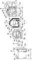
图3是分解地表示实施形态的照明器具的端部的立体图。 Fig. 3 is an exploded perspective view showing an end portion of the lighting fixture according to the embodiment. the
图4是表示实施形态的明器具的端板构件、衬垫、以及安装金属件的背面的立体图。 Fig. 4 is a perspective view showing the back side of an end plate member, a gasket, and a mounting bracket of the bright fixture according to the embodiment. the
图5A~图5B是表示实施形态的照明器具的衬垫部分,图5A是表示设置在端板构件与外罩构件之间的衬垫的部分放大的剖面图,图5B是表示电线插通部分的衬垫的部分放大的剖面图。 5A to FIG. 5B show the gasket portion of the lighting fixture according to the embodiment. FIG. 5A is a partially enlarged cross-sectional view showing the gasket provided between the end plate member and the cover member. A partially enlarged cross-sectional view of the liner. the
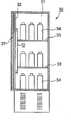
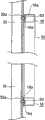
图6A~图6C是表示将实施形态的照明器具设置于陈列柜的状态,图6A是陈列柜的纵剖面图,图6B是将照明器具设置于柱而成的部分放大并将一部分予以切开来表示的剖面图,图6C是表示将照明器具安装于安装金属件的状态的立体图。 6A to 6C show the state where the lighting fixture according to the embodiment is installed in the showcase. FIG. 6A is a vertical cross-sectional view of the showcase, and FIG. 6B is an enlarged part of the lighting fixture installed on a column and a part cut away. Fig. 6C is a perspective view showing a state in which the lighting fixture is mounted on the mounting hardware. the
图7A、图7B是表示实施形态的第一变形例,图7A是表示附带灯口的灯的立体图,图7B是沿着图7A的B-B线的剖面图。 7A and 7B show a first modified example of the embodiment. FIG. 7A is a perspective view showing a lamp with a base, and FIG. 7B is a cross-sectional view along line B-B of FIG. 7A . the
图8是表示实施形态的第二变形例的立体图。 Fig. 8 is a perspective view showing a second modified example of the embodiment. the
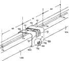
图9A、图9B是表示实施形态的第三变形例,图9A是表示连结部分的立体图,图9B是将图9A的A部分予以放大的立体图。 9A and 9B show a third modified example of the embodiment. FIG. 9A is a perspective view showing a connecting portion, and FIG. 9B is an enlarged perspective view of part A of FIG. 9A . the
符号的说明: Explanation of symbols:
10:照明装置 10: lighting device
10A、10B:照明器具 10A, 10B: lighting fixtures
11:光源单元 11: Light source unit
11a:基板 11a: Substrate
11a1:基板安装板 11a1: Substrate mounting plate
11b:LED/固态发光元件 11b: LED/solid-state light-emitting components
11c:发光部 11c: Luminous Department
11c1:连接器 11c1: connector
11d:点灯装置 11d: lighting device
11d1:电子零件 11d1: Electronic components
11d2:电路基板 11d2: circuit substrate
11d3:间隔件 11d3: spacer
11d4:绝缘外罩 11d4: Insulating cover
11e:支撑壳 11e: Support shell
11e1:开放部 11e1: Open Department
11e2:凸缘部 11e2: flange part
11e3:支撑端板 11e3: Support end plate
11e4:螺钉孔 11e4: screw holes
11f:突出片 11f: protruding piece
12:筒状外罩构件/外罩构件 12: Cylindrical cover member/cover member
12a:开口 12a: Opening
12b:光透射部 12b: Light-transmitting part
12c、13c、14c:段部 12c, 13c, 14c: section
12d、13d、14d:两侧部 12d, 13d, 14d: both sides
12e、13e、14e:支撑凸条 12e, 13e, 14e: Supporting ribs
12f:安装部 12f: Installation department
13:端板构件 13: End plate member
13a:开口部 13a: Opening part
13b:半圆形部 13b: semicircular part
13f、14f:平坦部 13f, 14f: flat part
13g、14g:凸缘部 13g, 14g: flange part
13h、14h:衬垫支撑部 13h, 14h: pad support part
13h1、14h1、15h1、16d:插通孔 13h1, 14h1, 15h1, 16d: through holes
13j:电线插通孔 13j: Wire insertion hole
14:衬垫 14: Liner
14a:开口/开口部 14a: Opening/opening part
14b:半圆形部 14b: semicircular part
14j:电线衬垫/电线衬垫部 14j: Wire packing/wire packing part
14j1:电线密封孔 14j1: Wire sealing hole
14k:凸条部 14k: Convex part
15:螺钉用衬垫 15: Gasket for screws
16:安装金属件 16: Install metal parts
16a:基底部 16a: Basal part
16b:支撑片 16b: support piece
16b1:固定片 16b1: fixed piece
16c:覆盖部 16c: Covering Department
16e:槽 16e: slot
30:陈列柜 30: Showcase
31:门 31: door
32:柱 32: column
32a:螺钉孔 32a: Screw hole
33:搁板 33: shelf
34:饮料 34: Drinks
40:附带灯口的灯 40: Lamp with socket
41:灯口构件 41: lamp port component
42:灯口接脚 42: lamp socket pin
A:部分 A: some
a1:设置间隔/间距 a1: set interval/spacing
a2:间距 a2: Spacing
B-B:线 B-B: line
C1:胶皮绝缘软电缆 C1: rubber insulated flexible cable
H:高度 H: height
h1、h2:高度尺寸 h1, h2: height dimension
L:全长 L: full length
S1:螺钉 S1: screw
S2:自攻螺钉 S2: self-tapping screw
S3:螺钉 S3: screw
W:宽度 W: width
w1:间隔尺寸 w1: interval size
具体实施方式Detailed ways
参照附图来对本发明的一个实施方式的照明装置进行说明,就某些观点而言,附图中的相同或类似的参照序号表示相同或相符的部分。 A lighting device according to one embodiment of the present invention will be described with reference to the drawings, and the same or similar reference numerals in the drawings represent the same or corresponding parts from some points of view. the
第一实施方式 first implementation
本实施方式的照明装置构成陈列柜用的呈直管状且具有防水功能的照明装置10。如图1A、图1B所示,照明装置10包括:光源单元11,具有沿着呈矩形状的基板11a的长度方向而配设有固态发光元件11b的发光部11c、及对固态发光元件进行点灯的点灯装置11d;以及透光性的筒状外罩构件12,其剖面为非圆形且在两端具有开口12a,且大致呈直管状。再者,外罩构件12是由热膨胀系数比光源单元11的热膨胀系数更大的构件构成。而且,端板构件13将外罩构件12的两端的开口12a予以闭塞,并且固定于光源单元11的两端部。 The lighting device of the present embodiment constitutes a straight pipe-shaped
光源单元11是由光源部构成,该光源部包括:发光部11c,包含呈矩形状的基板11a、与沿着基板的长度方向来配设的固态发光元件11b;以及对固态发光元件进行点灯的点灯装置11d。基板11a是由电绝缘性良好的构件构成,在本实施方式中是由呈平板状的薄且细长的矩形状的包含玻璃环氧(glass epoxy)树脂的电路基板构成,在该基板11a的表面(图1B中的上方的面)上形成有包含铜箔的配线图案(pattern)。而且,在该配线图案上,多个固态发光元件11b大致呈直线状且大致等间隔地配设成一列。 The
如图2所示,在本实施方式中,固态发光元件11b是由发光二极管(以下称为“LED”)构成,该固态发光元件11b由多个LED构成,例如由4 个表面安装器件(Surface Mounted Device,SMD)型的LED构成。借由所述各LED11b以及基板11a来构成平板状的薄且细长的矩形状的发光部11c。再者,4个所述LED11b串联地连接。另外,LED也可为如下的类型的板上芯片(Chip On Board,COB)形的LED,该类型的COB形的LED借由多个LED芯片(chip)以及由该LED芯片所激发的荧光体来发出白色(包括自然白色、日光色、以及白炽灯色)的光。 As shown in Figure 2, in this embodiment, the solid-state light-emitting
所述发光部11c支撑于基板安装板11a1。该基板安装板11a1是由具有导热性的金属构成,在本实施方式中是由呈平板状的薄且细长的矩形状的钢板构成。在该基板安装板11a1的表面上,使发光部11c以及基板安装板11a1的轴线相吻合地,沿着基板安装板11a1的长度方向来将多块发光部配设成一列,在本实施方式中是将4块发光部11c配设成一列。如图1B所示,各发光部11c借由螺钉S1而固定于基板安装板11a1。4块发光部11c借由连接器(connector)11c1而电性连接。 The
点灯装置11d是由将100V的交流电压转换为24V的直流电压并将定电流的直流电流供给至LED11b的点灯电路构成,该点灯装置11d包括:构成该点灯电路的电子零件11d1、与用以安装电子零件的电路基板11d2。该电路基板11d2与发光部11c的基板11a同样地是由呈平板状的薄且细长的矩形状的玻璃环氧树脂构成,在该电路基板11d2的单面或两个面上形成有电路图案,在该电路基板11d2的安装面上安装有多个小形的电子零件11d1。 The
如图1B所示,在与发光部11c的基板11a的发光面不同的部分,即本实施方式中的基板11a的背面即基板安装板11a1的背面,借由具有电绝缘性的合成树脂制的间隔件(spacer)11d3,即本实例中的聚对苯二甲酸乙二醇酯(Polybutylene Terephthalate,PBT)制的间隔件11d3,保持规定的间隔并利用螺钉S1来将以所述方式构成的点灯装置11d的电路基板11d2支撑于基板安装板11a1的背面。借由该螺钉S1来同时对发光部11c 的基板11a与基板安装板11a1进行固定。光源单元11是利用导线(未图示)来将构成点灯装置11d的电路基板11d2的输出端子、与发光部11c的基板11a的输入端子予以连接,该光源单元11由发光部11c与对LED11b进行点灯的点灯装置11d构成。而且,包含发光部11c与点灯装置11d的光源部配设在长度方向上。再者,在本实施方式中,由于利用1台点灯装置来将2块发光部11c予以驱动,因此,相对于4块发光部11c,构成有2台点灯装置。 As shown in FIG. 1B , the portion different from the light-emitting surface of the
如图2所示,对于以所述方式构成的光源单元11而言,发光部11c面向外方,点灯装置11d收纳在支撑壳11e内。支撑壳11e是以如下的方式构成,即,对与基板安装板11a1同样地具有导热性的金属进行压制加工,在本实施方式中,对钢板进行压制加工,借此来在上表面形成开放部11e1,在放部的两侧一体地形成凸缘部11e2,在两端一体地形成支撑端板11e3,形成细长的长条的箱体。另外,在两端的支撑端板11e3中,形成用以对后述的端板构件13进行固定的2个螺钉孔11e4。 As shown in FIG. 2, in the
所述光源单元11以长度方向沿着箱体的长度方向的方式,配设在以所述方式构成的支撑壳11e的箱体的内部。此时,以如下的方式来进行配设,即,发光部11c即各LED11b面向外方,构成点灯装置11d的电路基板11d2收纳在支撑壳11e内。再者,借由具有电绝缘性的构件,在本实施方式中借由包含硅酮(silicone)树脂的绝缘外罩11d4来将构成点灯装置11d的电路基板11d2予以覆盖,与由金属构成的支撑壳11e电性绝缘地收纳该电路基板11d2。 The
另外,光源单元11的基板安装板11a1的宽度尺寸形成为与支撑壳11e的两侧的凸缘部11e2之间的宽度尺寸大致相同的尺寸,而且,基板安装板11a1的长度尺寸形成为与支撑壳11e的长度尺寸大致相同的尺寸,借由基板安装板11a1来将支撑壳11e上表面的开放部11e1予以闭塞。基板安装板11a1也可借由螺钉或接着剂等的方法而固定于支撑壳11e两侧的凸缘 部11e2的上表面。 In addition, the width dimension of the substrate mounting plate 11a1 of the
如上所述,发光部11c面向外方且点灯装置11d收纳在支撑壳11e内的光源单元11插入且收容在筒状的外罩构件12内。如图3所示,外罩构件12是由热膨胀系数比光源单元11的热膨胀系数更大的透光性的合成树脂构成,在本实施方式中是由透明的丙烯酸树脂构成,该外罩构件12形成为在两端具有开口12a且呈长条的大致直管状的筒形。外罩构件12包括:光透射部12b,其剖面与发光部11c相对向且大致形成为半圆形;两侧部12d,具有设置于光透射部的两侧的段部12c;设置于底面的支撑凸条12e;以及安装部12f,大致呈平坦状地形成于所述支撑凸条12e的两侧。外罩构件12是以剖面形状成为非圆形的方式,借由树脂成形而一体地形成。两侧的段部12c以段部的内表面侧来对光源单元11进行定位,并且以段部的外表面侧来支撑于后述的安装金属件16。 As described above, the
长条的光源单元11从一个开口12a沿着外罩构件的长度方向而插入且收容在以所述方式构成的筒状构件即外罩构件12中。即,使因光源单元11的基板安装板11a1与支撑壳11e的凸缘部11e2重叠而朝两侧突出地构成的突出片11f的上表面,抵接于外罩构件12两侧的段部12c内表面侧的下表面,而且使支撑壳11e的下表面抵接于支撑凸条12e。接着,一面将两侧的段部12c内表面侧以及支撑凸条12e的上表面作为引导件来对光源单元11进行定位,一面从外罩构件12的一个开口12a将长条的光源单元11的一端部予以插入。换句话说,作为筒状构件的外罩构件12是以使光源单元11可在外罩构件12的轴方向上移动的方式而收容着该光源单元11,并且在与轴正交的方向上进行位置限制。借此,可简化组装作业,且可确实地将光源单元11收容在外罩构件12中。 The elongated
根据所述内容,插入且收容在外罩构件12中的光源单元11的两端部,被将外罩构件的两端的开口12a予以闭塞的端板构件13固定。如图3、图4所示,端板构件是形成为在具有电绝缘性的合成树脂制的一侧面侧具有 开口部13a的顶盖形状,在本实例中是形成为在PBT(聚对苯二甲酸乙二醇酯)制的一侧面侧具有开口部13a的顶盖形状。所述端板构件13的剖面形状是以可嵌合于外罩构件12的开口12a的方式而形成为与外罩构件12的剖面形状大致相同的外表面形状,且形成为稍小的外形尺寸。即,如图4所示,在上表面形成半圆形部13b,在该半圆形部13b的两侧形成以具有段部13c的方式而形成的两侧部13d,在底面形成支撑凸条13e,分别借由树脂成形来将平坦部13f一体地形成于所述支撑凸条的单侧。而且,将凸缘部13g一体地形成于开口部13a的外周部,使呈椭圆形状的衬垫(packing)支撑部13h一体地突出形成于顶盖的内底面的大致中央部,在该底面上形成螺钉插通用的2个插通孔13h1,该螺钉插通用的2个插通孔13h1与形成于所述支撑壳11e的支撑端板11e3的2个螺钉孔11e4连通。再者,如图4所示,衬垫支撑部13h形成为也向外表面侧突出。图中,13j是形成在开口部13a的下方的角部的用以供电源线插通的电线插通孔。 As described above, both ends of the
如图4所示,以所述方式构成的端板构件13从外罩构件12的一端的开口12a嵌入,但在本实施方式中,如图3所示,兼具有缓冲与密闭的功能的衬垫14介于且嵌入在端板构件13与外罩构件的开口之间。衬垫是由具有柔软性的构件构成,例如在本实施方式中是由硅酮橡胶构成,且形成为在一侧面侧具有开口14a的顶盖状。此外,与端板构件13的外表面形状大致相同地形成所述衬垫14的内表面形状,而且,与外罩构件12的剖面形状大致相同地形成所述衬垫14的外表面形状,且形成为稍大的外形尺寸。即,在两侧部14d底面形成支撑凸条14e,分别借由成形步骤来将平坦部14f一体地形成于支撑凸条的单侧,所述两侧部14d形成为在上表面具有半圆形部14b,且在半圆形部的两侧具有段部14c。此外,将凸缘部14g一体地形成于开口部14a的外周部,使呈椭圆形状的衬垫支撑部14h一体地突出形成于顶盖的内底面的大致中央部,在该衬垫支撑部14h的底面形成螺钉插通用的2个插通孔14h1,该2个插通孔14h1与形成于所述 端板构件13的衬垫支撑部13h的2个插通孔13h1连通。再者,衬垫支撑部14形成为向外表面侧突出。 As shown in FIG. 4 , the
如图5A、图5B所示,图中的14j是对应于端板构件13的电线插通孔13j,以密着于电线插通孔13j的方式而形成于衬垫14的电线衬垫,该电线衬垫形成有供两根电源线与一根地线插通的3个电线密封孔14j1。而且,在衬垫14的内表面以及外表面的表面上,沿着圆周方向而一体地形成有多个凸条部14k。另外,在电线衬垫部14j的3个电线密封孔14j1的内表面的表面上,也沿着外周方向而一体地形成有多个凸条部14k。另外,图中的15是由硅酮橡胶构成且呈椭圆形的薄板状的螺钉用衬垫,该螺钉用衬垫密着且嵌合于所述端板构件13的椭圆形状的衬垫支撑部13h。在该螺钉用衬垫15中,形成有与端板构件13的2个插通孔13h1连通的2个插通孔15h1。 As shown in FIGS. 5A and 5B, 14j in the figure corresponds to the
对应于外罩构件12的左右两端的开口12a,设置有以所述方式构成的一对端板构件13、一对衬垫14、以及一对螺钉用衬垫15,所述端板构件13、衬垫14以及螺钉用衬垫15固定于插入且收容在外罩构件12中的光源单元11的两端部。该固定构成在左右两端均相同,以下,如图1A所示,以左方的构成来进行说明。 Corresponding to the
首先,使衬垫14的内周部与端板构件13的外周部吻合并嵌入至该端板构件13的外周部。此时,如图5A所示,在衬垫14的内周面的表面上,沿着圆周方向而形成多个凸条部14k,凸条部利用衬垫的弹性而弯曲,借此,端板构件13的外周部与衬垫14的内周部气密地密着并嵌合。同时,衬垫14的电线衬垫14j的表面利用衬垫的弹性而气密地密着并抵接于端板构件13的电线插通孔13j的背面侧。另外,端板构件13的2个插通孔13h1与衬垫14的2个插通孔14h1相吻合地连通。此外,在衬垫14嵌合于端板构件13的状态下,各自的凸缘部13g、14g的顶点(外周部)处于同一个面而突出。 First, the inner peripheral portion of the
如上所述,将衬垫14嵌合于端板构件13经一体化而成的构件,嵌入至预先插入且收容着光源单元11的筒状的外罩构件12的两端的开口12a。对于该嵌合而言,使嵌合于端板构件13的外周部的状态下的衬垫14的外周部与外罩构件12的开口12a吻合并嵌入至该外罩构件12的开口12a。此时,如图5A所示,在衬垫14的外周面的表面上,沿着圆周方向而形成多个凸条部14k,凸条部利用衬垫的弹性而弯曲,借此,衬垫14的外周部与外罩构件12的内周部气密地密着并嵌合。同时,端板构件13的电线插通孔13j与衬垫14的电线密封孔14j1连通。此外,对于端板构件13的凸缘部13g与衬垫14的凸缘部14g而言,外周部处于同一个面而突出,并密着且抵接于外罩构件12的开口12a端面。另外,端板构件13的凸缘部13g及衬垫14的凸缘部14g的外周部与外罩构件12的外表面处于同一个面,从而使外观形状良好。 As described above, the
接着,将螺钉用衬垫15嵌合于端板构件13的衬垫支撑部13h。此时,螺钉用衬垫15的2个插通孔15h1、端板构件13的2个插通孔13h1、以及衬垫14的2个插通孔14h1分别成为连通的状态。而且,以两侧的段部12c的内表面侧作为引导件来对光源单元11进行定位,换句话说,在与外罩构件12的轴方向正交的方向上进行位置限制,因此,所述多个插通孔与2个螺钉孔11e4成为位置已对准的状态。 Next, the
在所述状态下,将两根螺钉,在本实施方式中是将自攻螺钉(tapping screw)S2插通于螺钉用衬垫15的2个插通孔15h1,该自攻螺钉S2经由端板构件13的插通孔13h1、13h1以及衬垫14的插通孔14h1、14h1而旋入且固定于光源单元11的支撑端板11e3的螺钉孔11e4、11e4。所述自攻螺钉S2同样地旋入至嵌合于左右两端的开口12a的端板构件13。借由所述自攻螺钉S2的旋入,左右的端板构件13以及衬垫14被向各个支撑端板11e3挤压(图1B中的箭头方向)。借由该挤压,衬垫14的凸缘部14g夹在端板构件13的凸缘部13g与外罩构件12的开口12a的端面之间,衬 垫14对抗其弹性而被压缩,从而气密地密着于所述凸缘部13g与开口12a的端面。 In this state, two screws, in this embodiment, a tapping screw (tapping screw) S2 are inserted into the two insertion holes 15h1 of the screw packing 15, and the tapping screw S2 passes through the end plate. The insertion holes 13h1 and 13h1 of the
外罩构件12是以如下的方式形成,即,剖面形状构成为非圆形,且具有内周面的形状平滑地连续的表面。因此,衬垫14的外周面的凸条部14k利用其柔软性而追随着外罩构件12的内周面的形状并产生变形,从而更确实地保持气密性。 The
另外,筒状的外罩构件12是由热膨胀系数大的合成树脂构成,而作为光源单元11的构成零件的支撑壳11e等是由金属构成。因此,外罩构件12与光源单元11之间会产生热膨胀系数之差,根据使用环境中的温度,由热膨胀系数大的丙烯酸树脂构成的外罩构件12与光源单元11相比,会更大幅度地膨胀或收缩,细长的呈直管状的外罩构件的长度会发生变化。 In addition, the
但是,根据本实施方式,即使当外罩构件的长度发生变化时,仍可保持气密状态。即,当因热而发生膨胀时,外罩构件12会稍微变长,但衬垫14的弹性力的伸缩会充分地吸收所述膨胀,从而成为更加密着的状态。另外,例如即使当照明装置用以对-25℃左右的冷冻库等进行照明,外罩构件12发生收缩而变短时,借由衬垫14的弹性,衬垫的凸缘部14g充分地追随着所述外罩构件12而弹性复原,从而仍保持密着的状态。 However, according to the present embodiment, even when the length of the cover member changes, the airtight state can be maintained. That is, when expansion due to heat occurs, the
另外,如上所述,光源单元11的突出片11f的上表面抵接于外罩构件12的段部12c内表面侧,而且支撑壳11e的下表面抵接于支撑凸条12e,以这些构件为引导件来进行定位,并收容该光源单元11。即,光源单元11仅支撑且固定于端板构件13,而并不固定于作为筒状构件的外罩构件12。换句话说,外罩构件12可相对于光源单元11而在轴长度方向上移动,并且在与长度方向正交的方向上,位置受到限制。 In addition, as described above, the upper surface of the protruding
因此,即使由树脂构成的外罩构件12因热而发生膨胀、收缩,该膨胀、收缩的应力也不易传递至光源单元11,从而不易对光源单元11产生影响。同时,来自外罩构件12的振动或冲击由也作为缓冲构件的衬垫14 所吸收,因此,不易传递至光源单元11,从而可构成对于振动或冲击的耐受性强的照明器具。 Therefore, even if the
另外,如上所述,衬垫14的凸缘部14g与端板构件13的凸缘部13g借由衬垫而气密地密着,同时,端板构件13的电线插通孔13j被挤压于衬垫14的电线衬垫14j,电线插通部分气密地密着。此外,两根自攻螺钉S2的头部挤压于螺钉用衬垫15的表面,螺钉插通部分气密地密着。 In addition, as described above, the
借此,如图6A~图6C所示,光源单元11的两端部借由端板构件13与衬垫14而气密地密着于外罩构件12的两端的开口12a,从而构成具有防水功能的陈列柜或冷冻库用的呈直管状的照明器具10。本实施方式中的照明器具构成为全长L约为1200mm、宽度W约为37mm、高度H约为39mm的细长的长条的照明器具。图中,16是用以将以所述方式构成的照明器具10设置于被设置部内的安装金属件,在本实施方式中是用以将以所述方式构成的照明器具10设置于陈列柜的库内的安装金属件,对具有固定的刚性且可产生弹性的构件进行压制加工,在本实施方式中是对不锈钢进行压制加工,借此来构成所述安装金属件。如图3所示,安装金属件包括:平坦的基底部16a;一对支撑片16b,借由大致向垂直方向弯折地形成基底部的两端部来产生弹性;以及覆盖部16c,从与支撑片正交的边大致向垂直方向立起。在基底部16a形成用以供固定用的螺钉插通的由长孔构成的插通孔16d,向内方将一对支撑片16b的上端部予以弯折,从而一体地形成固定片16b1。一对支撑片16b之间的间隔尺寸w1形成为与外罩构件12的宽度尺寸W2大致相等的尺寸(W1 W2),为了具有弹性,直至一对支撑片中的固定片16b1为止的高度尺寸h1形成为比直至外罩构件12的段部12c为止的高度尺寸h2稍低的尺寸(h1<h2)。为了对外罩构件12的左右两端部进行固定,准备2个具有相同构成的所述构成的安装金属件16。 Thereby, as shown in FIGS. 6A to 6C , both ends of the
以所述方式构成的照明器具10是以如下的方式而设置在陈列柜中。 如图6A~图6C所示,30是用以冷藏地储藏饮料等的双开式的陈列柜,在位于双开的门31的接缝的柱32的背面侧,设置有所述构成的照明器具10。在柱32中,沿着长度方向而预先上下地形成有2个设置用的螺钉孔32a。使形成在所述构成的安装金属件16的基底部16a的插通孔16d与所述螺钉孔吻合,将螺钉S3予以旋入来进行固定。此时,利用插通孔16d的长孔尺寸来对安装金属件16的设置位置进行调整,使上下2个安装金属件之间的尺寸与照明器具10的长度尺寸相匹配地进行固定。 The
如上所述,在固定于柱32的安装金属件16上固定照明器具10。首先,如图6C所示,外罩构件12的安装部12f对抗着一对支撑片16b的弹性,一面挤开各支撑片16b,一面插入至安装金属件16的一对支撑片16b的间隔内,外罩构件12的平坦的安装部12f抵接于安装金属件16的平坦的基底部16a。 As described above, the
借由所述插入操作,各支撑片16b的固定片16b1沿着外罩构件12的两侧部12d而弯曲并移动,借由支撑片16b的弹性,固定片16b1落入至外罩构件的段部12c的上表面。借此,固定片16b1利用由其弹性产生的弹性力而卡止于外罩构件的段部12c的外表面,照明器具10沿着纵方向即柱32的长度方向而受到固定。当将照明器具10予以拆除时,与所述相反地,利用手指等来推开各支撑片16b,将固定片16b1与段部12c的卡止状态予以解除,接着将照明器具从支撑片16b1上抽出即可。 By the inserting operation, the fixing piece 16b1 of each
再者,用于照明器具10的光源单元的电源线的配线动作是在设置照明器具之前进行的,其将预先从柱32导出的电线予以连接,在本实施方式中是将剖面为圆形状的胶皮绝缘软电缆(cabtire cable)C1予以连接。胶皮绝缘软电缆C1包括两根电源线与一根地线共计3根电线,这些电线插通在形成于照明器具10的衬垫14的电线密封孔14j1中,并连接于光源单元11的输入端子。 Furthermore, the wiring operation of the power cord for the light source unit of the
此时,如图5B所示,在电线密封孔14j1的内表面上,沿着圆周方向 而形成多个凸条部14k,凸条部利用其弹性而密着于电线C1的表面,保持电线插通部分的气密性。再者,当将电线予以连接时,在将经一体化的端板构件13以及衬垫14从光源单元11上拆除的状态下进行连接,将电线予以连接之后,再次将所述端板构件13以及衬垫14固定于光源单元11,并将外罩构件12的开口12a予以堵塞。图中的33是设置在陈列柜30的库内的上下的搁板,34是载置于各搁板并被陈列的塑料瓶(plastic bottle)等的饮料。 At this time, as shown in FIG. 5B, on the inner surface of the electric wire sealing hole 14j1, a plurality of
如上所述,使设置于门31的背面侧的照明器具10点灯之后,光源单元11中的发光部11c的各LED11b点灯而放射出光。从LED放射出的光经由外罩构件12的剖面为半圆形的光透射部12b,向大致沿着LED的配光的方向放射。该光从配设于上下方向的各LED11b向左右方向扩散,从而可在上下方向上,大致均等地对设置于上下方向的各搁板上所陈列的饮料等进行照射。另外,当库内产生的露水或溢出的水等落在照明器具10上时,对于本实施方式的照明器具10而言,由于端板构件13与外罩构件12之间、螺钉插通部分、以及电线插通部分借由衬垫14、15而保持着气密性,因此,不会被水浸入。另外,也不会被尘土或尘埃等侵入。 As described above, after lighting the
另外,各LED11b所产生的热会从由钢板构成的基板安装板11a1散逸至外罩构件12内,从而防止LED的温度上升。另外,点灯装置11d的电子零件11d1所产生的热会从由钢板构成的支撑壳11e散逸至外罩构件12内,从而防止电子零件的温度上升。再者,在所述内容中,构成了构成新颖的陈列柜用的照明器具,但本实施方式的照明器具是设置本实施方式的照明器具,来代替已设置的陈列柜中的荧光灯式的照明器具,从而也进一步节能或使寿命更长。 In addition, the heat generated by each
以上,在本实施方式中,将照明器具10纵向地设置于双开式的陈列柜30,但也可横向地设置该照明器具10。另外,不限于陈列柜,例如也可用以对室外的停车场的收费机等进行照明。在此情况下,即使在室外暴 露在风雨下,也可与所述同样地防止雨水等的水的浸入、以及尘土或尘埃等的侵入。另外,不限于所述已例示的用途,也可适用于其他的住宅用或店铺、办公室(office)等设施、业务用等的各种照明器具。 As mentioned above, in this Embodiment, although the
此外,在所述内容中构成了照明器具,但也可构成附带灯口的灯。如图7A、图7B所示,40是在外罩构件的一端部设置有灯口构件41的直管状的附带灯口的灯,借由树脂成形来将一对灯口接脚(pin)42一体地植设在由所述的具有电绝缘性的树脂构成的一个端板构件13中,从而构成所述灯口构件41。另外,灯口接脚42的一端与光源单元11的输入端子借由导线而电性连接,另一端从一个端板构件13向外方突出。 In addition, although the lighting fixture is comprised in the said content, you may comprise the lamp with a socket. As shown in FIGS. 7A and 7B , 40 is a straight tubular lamp with a cap with a
借此,由于本实施方式中的照明器具内置有点灯装置11d,因此,可提供如下的附带灯口的灯40,该附带灯口的灯40只要将本变形例中的灯口接脚42插入至例如与现有的荧光灯中的插座(socket)同样地构成且连接于电源的插座的接受侧端子,就可点灯。 Thus, since the lighting device in this embodiment has a built-in
在本实施方式中,固态发光元件是由LED构成,但也可由半导体激光(laser)、有机电致发光(Electroluminescence,EL)等的固态发光元件构成。固态发光元件呈直线状地安装于细长的矩形状的基板,但也可将多个固态发光元件配置为矩阵状,或配置为锯齿状或放射状等规则地具有固定的顺序且整体配置为面状来进行安装。 In this embodiment, the solid-state light-emitting element is composed of LEDs, but it may also be composed of solid-state light-emitting elements such as semiconductor lasers (lasers) and organic electroluminescence (Electroluminescence, EL). The solid-state light-emitting elements are linearly mounted on the elongated rectangular substrate, but it is also possible to arrange a plurality of solid-state light-emitting elements in a matrix, or in a zigzag or radial pattern, etc., with a fixed order and overall arrangement as a plane. status to install. the
另外,在本实施方式中,使用4块发光部11c来构成光源单元11,但也可将发光部11c以及点灯装置11d模块化为例如约600mm左右的长度而构成光源单元,适当地选择该模块的个数,借此来构成与用途相匹配的长度的各种照明器具。 In addition, in the present embodiment, the
另外,在本实施方式中,利用平板来构成配设有发光部11c的基板安装板11a1,并使收纳着点灯装置11d的支撑壳11e为箱体,但如图8所示,相反地也可利用箱体来构成基板安装板11a1,将发光部11c配设于箱体的外表面,并将点灯装置11d收容在箱体内部。 In addition, in the present embodiment, the substrate mounting plate 11a1 on which the
另外,外罩构件12也可以使光扩散的方式而形成为乳白色等的半透明。另外,也可利用透明或半透明的玻璃来构成所述外罩构件12。此外,也可将所述外罩构件着色为蓝色或红色等。 In addition, the
利用玻璃环氧树脂来构成基板11a以及点灯装置11d的电路基板11d2,但也可利用导热性良好的铝等的金属或陶瓷来构成所述基板11a以及点灯装置11d的电路基板11d2。另外,利用钢板来构成基板安装板11a1以及支撑壳11e,但也可利用导热性良好的铝铸件(aluminium die cast)来构成所述基板安装板11a1以及支撑壳11e,从而发挥更有效果的散热作用。 The
另外,安装金属件16也可构成为还具有用以将多台照明器具予以连结的功能。即,如图9A、图9B所示,将安装金属件16的长度方向的尺寸形成为大尺寸,并且将覆盖部16c予以削除,形成两端开放的一对基底部16a,一体地将该一对基底部的彼此相对向的开放面侧的大致一半予以连结,从而形成一体的宽阔的支撑片16b。另外,在支撑片16b与固定片16b1的分界线处,且在长度方向的大致中间部分形成一对槽16e。当照明器具10插入至该槽时,树脂制的端板构件13的凸缘部13g的下边两角部嵌合,防止器具向水平方向偏移,从而对连结的各照明器具进行定位。因此,针对连结的照明器具而分别各设置2个槽16e,以相对向的方式而分离地设置4个槽16e。 In addition, the mounting
以所述方式构成的安装金属件16能够以如下的方式来将多台照明器具予以连结并进行设置。首先,使用安装金属件16的宽阔的一个支撑片16b来对连结的一个照明器具10A的端部进行支撑。接着,将照明器具10A中的端板构件13的凸缘部13g的下边两角部嵌合于槽16e,在水平方向即长度方向上进行定位。接着,也同样地使用安装金属件16的另一个支撑片16b来对另一个照明器具10B进行支撑。然后,将照明器具10B中的端板构件13的凸缘部13g的下边的两角部嵌合于槽16e,在长度方向上进行定位。 The mounting
借此,借由安装金属件16来将2台照明器具10A、10B予以连结,使得连结部分的间隙为最小限度,且在外观上成为一根连续的长条的照明器具。另外,在将3台照明器具予以连结的情况下,再准备所述构成的安装金属件,并与所述同样地进行连结即可。如此,借由准备所需个数的所述构成的安装金属件,可简单地将所需台数的照明器具予以连结。再者,与所述同样地,在安装金属件16预先固定于被设置部的状态下,进行所述连结操作。图9A、图9B中,S3是插通于基底部16a中所形成的插通孔16d且旋入至被设置部的螺钉。 Thereby, the two
根据所述构成,可简单地利用安装金属件来将多台照明器具予以连结,同时可简单地将多台照明器具设置于被设置部。此外,由于可借由槽16e来对照明器具进行定位并连结该照明器具,因此,如图所示,可与各器具中的间距a2同样地(a1 a2),构成连结部分的相邻接的各照明器具中的LED11b的设置间隔(间距(pitch))a1。借此,连结的多台照明器具中的发光部的设置间隔大致相等,所述连结部分的间隙为最小限度,相应地成为一根更连续的照明器具,可沿着长度方向来均等地进行照明。 According to the above configuration, a plurality of lighting fixtures can be easily connected by using the attachment metal fittings, and at the same time, a plurality of lighting fixtures can be easily installed in the installation portion. In addition, since the lighting fixture can be positioned and connected by the
以上,根据本实施方式,可提供能够以如下的方式来组装的照明器具或附带灯口的灯等照明装置,作为筒状构件的外罩构件12是以可使光源单元11在轴方向上移动的方式而收容着该光源单元11,并且在与轴正交的方向上进行位置限制,利用端板构件13来对光源单元11进行支撑,借此,即便使用热膨胀系数不同的构件,也不会产生故障。 As described above, according to the present embodiment, it is possible to provide a lighting device such as a lighting fixture or a lamp with a cap that can be assembled in such a manner that the
另外,筒状的外罩构件12是由热膨胀系数大的合成树脂构成,作为光源单元11的主要构成零件的基板安装板11a1等是由金属构成,由热膨胀系数大的丙烯酸树脂构成的外罩构件12与光源单元相比,会大幅度地膨胀或收缩,外罩构件的长度会发生变化。但是,根据本实施方式,光源单元11仅固定于端板构件13,而并不固定于外罩构件12。换句话说,外罩构件12是以可使光源单元11在外罩构件12的轴方向上移动的方式而收容着该光源单元11,并且在与轴正交的方向上进行位置限制,借由端板 构件13来对所述光源单元11进行支撑,因此,即使由树脂构成的外罩构件12因热而发生膨胀、收缩,该膨胀、收缩的应力也不易施加于光源单元11,从而不会对光源单元产生影响。而且,可构成对于苛刻的使用环境的温度不易产生故障的照明装置。而且,由于来自外罩构件12的振动或冲击被衬垫14吸收,因此,不易传递至光源单元11,从而可提供对于振动或冲击的耐受性强的照明装置。另外,即使作为筒状构件的外罩构件的长度发生变化,也可借由具有缓冲功能的衬垫14的弹性力来充分地吸收该变化,从而能够提供可充分地确保气密性以及防水性的照明装置。 In addition, the
另外,外罩构件12的剖面构成为非圆形,该外罩构件12形成为内周面的形状平滑地连续的表面,因此,衬垫14利用其柔软性而追随着外罩构件的内周面的形状并产生变形,从而保持气密性。因此,可确保更确实的防水性。另外,由于外罩构件12的剖面构成为非圆形,因此,可形成底面为平坦的面的安装部12f,可使该平坦的安装部密着于安装金属件16的平坦的基底部16a,将外罩构件确实地安装于安装金属件16。同时,容易确定器具的方向性。 In addition, the cross section of the
另外,外罩构件12的段部12c构成为以内表面来对光源单元11进行定位,并且以外表面来支撑于安装金属件16,因此,可将长条的光源单元的一端部从外罩构件12的一个开口12a插入。另外,可简化组装作业,且可将光源单元11确实地安装于外罩构件12。 In addition, the
以上所述,仅是本发明的较佳实施例而已,并非对本发明作任何形式上的限制,虽然本发明已以较佳实施例揭露如上,然而并非用以限定本发明,任何熟悉本专业的技术人员,在不脱离本发明技术方案范围内,当可利用上述揭示的结构及技术内容作出些许的更动或修饰为等同变化的等效实施例,但是凡是未脱离本发明技术方案的内容,依据本发明的技术实质对以上实施例所作的任何简单修改、等同变化与修饰,均仍属于本发明技术方案的范围内。 The above description is only a preferred embodiment of the present invention, and does not limit the present invention in any form. Although the present invention has been disclosed as above with preferred embodiments, it is not intended to limit the present invention. Anyone familiar with this field Those skilled in the art, without departing from the scope of the technical solution of the present invention, may use the structure and technical content disclosed above to make some changes or modifications to equivalent embodiments with equivalent changes, but any content that does not depart from the technical solution of the present invention, Any simple modifications, equivalent changes and modifications made to the above embodiments according to the technical essence of the present invention still fall within the scope of the technical solutions of the present invention. the
Claims (4)
Translated fromChinesePriority Applications (1)
| Application Number | Priority Date | Filing Date | Title |
|---|---|---|---|
| CN201410099130.5ACN103836419B (en) | 2010-06-10 | 2011-06-07 | Lighting device |
Applications Claiming Priority (4)
| Application Number | Priority Date | Filing Date | Title |
|---|---|---|---|
| JP2010-133409 | 2010-06-10 | ||
| JP2010-133369 | 2010-06-10 | ||
| JP2010133409AJP2011258476A (en) | 2010-06-10 | 2010-06-10 | Lighting device |
| JP2010133369AJP2011258474A (en) | 2010-06-10 | 2010-06-10 | Lighting device |
Related Child Applications (1)
| Application Number | Title | Priority Date | Filing Date |
|---|---|---|---|
| CN201410099130.5ADivisionCN103836419B (en) | 2010-06-10 | 2011-06-07 | Lighting device |
Publications (2)
| Publication Number | Publication Date |
|---|---|
| CN102278628Atrue CN102278628A (en) | 2011-12-14 |
| CN102278628B CN102278628B (en) | 2014-04-16 |
Family
ID=44118307
Family Applications (2)
| Application Number | Title | Priority Date | Filing Date |
|---|---|---|---|
| CN201410099130.5AExpired - Fee RelatedCN103836419B (en) | 2010-06-10 | 2011-06-07 | Lighting device |
| CN201110150411.5AExpired - Fee RelatedCN102278628B (en) | 2010-06-10 | 2011-06-07 | lighting device |
Family Applications Before (1)
| Application Number | Title | Priority Date | Filing Date |
|---|---|---|---|
| CN201410099130.5AExpired - Fee RelatedCN103836419B (en) | 2010-06-10 | 2011-06-07 | Lighting device |
Country Status (3)
| Country | Link |
|---|---|
| US (1) | US8740405B2 (en) |
| EP (1) | EP2395278A3 (en) |
| CN (2) | CN103836419B (en) |
Cited By (2)
| Publication number | Priority date | Publication date | Assignee | Title |
|---|---|---|---|---|
| CN102563430A (en)* | 2012-02-01 | 2012-07-11 | 天宝电子(惠州)有限公司 | LED fluorescent lamp with adjustable light projecting angle |
| CN111053930A (en)* | 2014-12-05 | 2020-04-24 | 首尔伟傲世有限公司 | Ultraviolet light-emitting diode lighting device |
Families Citing this family (13)
| Publication number | Priority date | Publication date | Assignee | Title |
|---|---|---|---|---|
| JP6067246B2 (en)* | 2011-06-30 | 2017-01-25 | 株式会社東芝 | Lighting device |
| TWM432757U (en)* | 2011-10-26 | 2012-07-01 | Enlight Corp | Lamp structure and lighting device |
| CN103511870B (en)* | 2012-06-27 | 2018-03-23 | 欧司朗股份有限公司 | Lighting device |
| GB2495355B (en)* | 2012-07-02 | 2013-08-28 | Gew Ec Ltd | Ink curing apparatus |
| ITFI20120246A1 (en)* | 2012-11-15 | 2014-05-16 | Consorzio Terranuova | "LIGHTING SYSTEM AND ITS COMPONENTS" |
| KR20150045221A (en)* | 2013-10-18 | 2015-04-28 | 삼성전자주식회사 | Lighting apparatus and lighting system |
| WO2016144819A1 (en)* | 2015-03-06 | 2016-09-15 | Power Probe TEK, LLC | Flexible work light |
| DE102015205030A1 (en) | 2015-03-19 | 2016-09-22 | Osram Gmbh | Semiconductor lamp |
| EP3117992A1 (en)* | 2015-07-16 | 2017-01-18 | AGC Glass Europe | Glass panel with integrated electronic device |
| DE202016100265U1 (en)* | 2016-01-21 | 2017-04-24 | Zumtobel Lighting Gmbh | Arrangement for forming an elongated receiving space for lighting units |
| KR101879295B1 (en)* | 2018-04-19 | 2018-07-18 | 비전엑스아시아(주) | Lamp assembly |
| JP7085927B2 (en)* | 2018-07-12 | 2022-06-17 | 三菱電機株式会社 | Lamps, lamp encapsulation structures, and lighting equipment |
| DE202022102292U1 (en)* | 2022-04-28 | 2023-08-10 | Zumtobel Lighting Gmbh | Elongated lamp with end cap and sealing function |
Citations (9)
| Publication number | Priority date | Publication date | Assignee | Title |
|---|---|---|---|---|
| CN2544180Y (en)* | 2002-04-28 | 2003-04-09 | 捷丽企业有限公司 | Waterproof lamps |
| JP2007035507A (en)* | 2005-07-28 | 2007-02-08 | Patoraito:Kk | Seal member and annunciator lamp |
| JP2007122945A (en)* | 2005-10-26 | 2007-05-17 | Matsushita Electric Works Ltd | Lighting device, luminaire using it and signboard lamp |
| CN101059229A (en)* | 2007-04-30 | 2007-10-24 | 深圳市鼎立照明有限公司 | U-shaped lamp |
| CN201078609Y (en)* | 2007-07-09 | 2008-06-25 | 李勇 | LED lamp guardrail tube |
| CN201232887Y (en)* | 2008-06-20 | 2009-05-06 | 深圳市联腾科技有限公司 | Lamp strip bulkhead structure and lamp strip applying the lamp strip bulkhead structure |
| CN201259109Y (en)* | 2008-09-24 | 2009-06-17 | 浙江捷莱照明有限公司 | High power LED lighting fixture |
| KR20100009201A (en)* | 2008-07-18 | 2010-01-27 | 안철용 | Led consist fabricate illumination lamp |
| CN101691923A (en)* | 2009-09-21 | 2010-04-07 | 珠海杰莱特照明有限公司 | Sealing element and unit body light fitting |
Family Cites Families (15)
| Publication number | Priority date | Publication date | Assignee | Title |
|---|---|---|---|---|
| JPH072317Y2 (en)* | 1991-02-21 | 1995-01-25 | スタンレー電気株式会社 | Cylindrical lamp for vehicle |
| DE4307531A1 (en) | 1993-03-10 | 1994-09-15 | Kodak Ag | Device for feeding X-ray film cassettes from a storage stock to a daylight loading and unloading device |
| US6135613A (en)* | 1998-06-18 | 2000-10-24 | Hubbell Incorporated | Lighting fixture assembly sealed at opposite ends with dust covers |
| US6158882A (en)* | 1998-06-30 | 2000-12-12 | Emteq, Inc. | LED semiconductor lighting system |
| US7273300B2 (en)* | 2004-08-06 | 2007-09-25 | Lumination Llc | Curvilinear LED light source |
| GB2429112A (en)* | 2005-08-09 | 2007-02-14 | Bright Group Pty Ltd | Diffuser tube for linear LED array with mounting slots for PCB and mounting frame |
| US7976196B2 (en)* | 2008-07-09 | 2011-07-12 | Altair Engineering, Inc. | Method of forming LED-based light and resulting LED-based light |
| CN201289050Y (en)* | 2008-09-05 | 2009-08-12 | 刘耀汉 | High-gloss LED lighting light pipe |
| JP2010097917A (en)* | 2008-10-20 | 2010-04-30 | Satoshi Miyauchi | Illuminating-display device |
| US8444292B2 (en)* | 2008-10-24 | 2013-05-21 | Ilumisys, Inc. | End cap substitute for LED-based tube replacement light |
| JP2010123359A (en)* | 2008-11-19 | 2010-06-03 | Rohm Co Ltd | Led lamp |
| CN201326984Y (en)* | 2008-11-28 | 2009-10-14 | 霍尼韦尔朗能电器系统技术(广东)有限公司 | Detachable LED lamp holder |
| US20100290218A1 (en)* | 2009-05-15 | 2010-11-18 | Yang mei-ling | Led lamp tube |
| TW201109587A (en)* | 2009-09-10 | 2011-03-16 | I Chiun Precision Ind Co Ltd | LED illuminate device capability of increasing illumination |
| KR20110121927A (en)* | 2010-05-03 | 2011-11-09 | 삼성엘이디 주식회사 | Lighting device using light emitting device package |
- 2011
- 2011-06-07CNCN201410099130.5Apatent/CN103836419B/ennot_activeExpired - Fee Related
- 2011-06-07EPEP11168946.9Apatent/EP2395278A3/ennot_activeWithdrawn
- 2011-06-07CNCN201110150411.5Apatent/CN102278628B/ennot_activeExpired - Fee Related
- 2011-06-09USUS13/157,123patent/US8740405B2/ennot_activeExpired - Fee Related
Patent Citations (9)
| Publication number | Priority date | Publication date | Assignee | Title |
|---|---|---|---|---|
| CN2544180Y (en)* | 2002-04-28 | 2003-04-09 | 捷丽企业有限公司 | Waterproof lamps |
| JP2007035507A (en)* | 2005-07-28 | 2007-02-08 | Patoraito:Kk | Seal member and annunciator lamp |
| JP2007122945A (en)* | 2005-10-26 | 2007-05-17 | Matsushita Electric Works Ltd | Lighting device, luminaire using it and signboard lamp |
| CN101059229A (en)* | 2007-04-30 | 2007-10-24 | 深圳市鼎立照明有限公司 | U-shaped lamp |
| CN201078609Y (en)* | 2007-07-09 | 2008-06-25 | 李勇 | LED lamp guardrail tube |
| CN201232887Y (en)* | 2008-06-20 | 2009-05-06 | 深圳市联腾科技有限公司 | Lamp strip bulkhead structure and lamp strip applying the lamp strip bulkhead structure |
| KR20100009201A (en)* | 2008-07-18 | 2010-01-27 | 안철용 | Led consist fabricate illumination lamp |
| CN201259109Y (en)* | 2008-09-24 | 2009-06-17 | 浙江捷莱照明有限公司 | High power LED lighting fixture |
| CN101691923A (en)* | 2009-09-21 | 2010-04-07 | 珠海杰莱特照明有限公司 | Sealing element and unit body light fitting |
Non-Patent Citations (1)
| Title |
|---|
| 陈国辉: "LED日光灯管的设计", 《机电工程技术》, vol. 39, no. 05, 31 May 2010 (2010-05-31), pages 47 - 52* |
Cited By (3)
| Publication number | Priority date | Publication date | Assignee | Title |
|---|---|---|---|---|
| CN102563430A (en)* | 2012-02-01 | 2012-07-11 | 天宝电子(惠州)有限公司 | LED fluorescent lamp with adjustable light projecting angle |
| CN111053930A (en)* | 2014-12-05 | 2020-04-24 | 首尔伟傲世有限公司 | Ultraviolet light-emitting diode lighting device |
| CN111053930B (en)* | 2014-12-05 | 2022-02-22 | 首尔伟傲世有限公司 | Ultraviolet light-emitting diode lighting device |
Also Published As
| Publication number | Publication date |
|---|---|
| CN102278628B (en) | 2014-04-16 |
| US20110305013A1 (en) | 2011-12-15 |
| EP2395278A3 (en) | 2014-01-15 |
| EP2395278A2 (en) | 2011-12-14 |
| US8740405B2 (en) | 2014-06-03 |
| CN103836419A (en) | 2014-06-04 |
| CN103836419B (en) | 2016-01-20 |
Similar Documents
| Publication | Publication Date | Title |
|---|---|---|
| CN103836419B (en) | Lighting device | |
| US8262249B2 (en) | Linear solid-state lighting with broad viewing angle | |
| JP2011258474A (en) | Lighting device | |
| US8858024B2 (en) | Illuminating apparatus and illuminating module | |
| CN202561482U (en) | Light-emitting module and lighting device | |
| US8899784B2 (en) | Display box lighting module | |
| EP2503234A2 (en) | Lamp device and luminaire | |
| JP2011258476A (en) | Lighting device | |
| WO2011122518A1 (en) | Tubular lamp and lighting equipment | |
| BRPI1012796A2 (en) | low profile housing | |
| US20140204572A1 (en) | System for Adapting an Existing Florescent Light Fixture with an LED Luminaire | |
| JP4941207B2 (en) | Illumination unit and illumination lamp using the same | |
| US8162516B2 (en) | LED reading lamp | |
| KR20090010850U (en) | Lighting device using LED as light source | |
| US20160025277A1 (en) | System for adapting an existing fluorescent light fixture with an LED luminaire | |
| KR20130092211A (en) | Light emitting diode lighting equipment | |
| KR20110088709A (en) | LED lighting device | |
| JP2012054018A (en) | Light-emitting element lamp and lighting fixture | |
| KR101061218B1 (en) | Heat Sink for LED Lighting | |
| US8789976B2 (en) | Integrated multi-layered illuminating unit and integrated multi-layered illuminating assembling unit | |
| KR100945173B1 (en) | Led lighting apparatus | |
| US20170089560A1 (en) | Outdoor light | |
| KR101075881B1 (en) | LED lighting system | |
| CN201137872Y (en) | Combination structure of outdoor lamps | |
| JP2013201041A (en) | Light-emitting module, lighting device, and lighting fixture |
Legal Events
| Date | Code | Title | Description |
|---|---|---|---|
| C06 | Publication | ||
| PB01 | Publication | ||
| C10 | Entry into substantive examination | ||
| SE01 | Entry into force of request for substantive examination | ||
| C14 | Grant of patent or utility model | ||
| GR01 | Patent grant | ||
| CF01 | Termination of patent right due to non-payment of annual fee | Granted publication date:20140416 Termination date:20180607 | |
| CF01 | Termination of patent right due to non-payment of annual fee |