CN102272959A - Surface deformation electroactive polymer transducer - Google Patents
Surface deformation electroactive polymer transducerDownload PDFInfo
- Publication number
- CN102272959A CN102272959ACN2009801543356ACN200980154335ACN102272959ACN 102272959 ACN102272959 ACN 102272959ACN 2009801543356 ACN2009801543356 ACN 2009801543356ACN 200980154335 ACN200980154335 ACN 200980154335ACN 102272959 ACN102272959 ACN 102272959A
- Authority
- CN
- China
- Prior art keywords
- transducer
- electrode
- active
- layer
- conductive
- Prior art date
- Legal status (The legal status is an assumption and is not a legal conclusion. Google has not performed a legal analysis and makes no representation as to the accuracy of the status listed.)
- Pending
Links
Images


Classifications
- H—ELECTRICITY
- H10—SEMICONDUCTOR DEVICES; ELECTRIC SOLID-STATE DEVICES NOT OTHERWISE PROVIDED FOR
- H10N—ELECTRIC SOLID-STATE DEVICES NOT OTHERWISE PROVIDED FOR
- H10N30/00—Piezoelectric or electrostrictive devices
- H10N30/80—Constructional details
- G—PHYSICS
- G06—COMPUTING OR CALCULATING; COUNTING
- G06F—ELECTRIC DIGITAL DATA PROCESSING
- G06F3/00—Input arrangements for transferring data to be processed into a form capable of being handled by the computer; Output arrangements for transferring data from processing unit to output unit, e.g. interface arrangements
- G06F3/01—Input arrangements or combined input and output arrangements for interaction between user and computer
- G06F3/02—Input arrangements using manually operated switches, e.g. using keyboards or dials
- G06F3/0202—Constructional details or processes of manufacture of the input device
- H—ELECTRICITY
- H10—SEMICONDUCTOR DEVICES; ELECTRIC SOLID-STATE DEVICES NOT OTHERWISE PROVIDED FOR
- H10N—ELECTRIC SOLID-STATE DEVICES NOT OTHERWISE PROVIDED FOR
- H10N30/00—Piezoelectric or electrostrictive devices
- H10N30/20—Piezoelectric or electrostrictive devices with electrical input and mechanical output, e.g. functioning as actuators or vibrators
- H10N30/206—Piezoelectric or electrostrictive devices with electrical input and mechanical output, e.g. functioning as actuators or vibrators using only longitudinal or thickness displacement, e.g. d33 or d31 type devices
- G—PHYSICS
- G06—COMPUTING OR CALCULATING; COUNTING
- G06F—ELECTRIC DIGITAL DATA PROCESSING
- G06F3/00—Input arrangements for transferring data to be processed into a form capable of being handled by the computer; Output arrangements for transferring data from processing unit to output unit, e.g. interface arrangements
- G06F3/01—Input arrangements or combined input and output arrangements for interaction between user and computer
- G06F3/03—Arrangements for converting the position or the displacement of a member into a coded form
- G06F3/041—Digitisers, e.g. for touch screens or touch pads, characterised by the transducing means
- G06F3/044—Digitisers, e.g. for touch screens or touch pads, characterised by the transducing means by capacitive means
- H—ELECTRICITY
- H10—SEMICONDUCTOR DEVICES; ELECTRIC SOLID-STATE DEVICES NOT OTHERWISE PROVIDED FOR
- H10N—ELECTRIC SOLID-STATE DEVICES NOT OTHERWISE PROVIDED FOR
- H10N30/00—Piezoelectric or electrostrictive devices
- H10N30/01—Manufacture or treatment
- H10N30/06—Forming electrodes or interconnections, e.g. leads or terminals
- H10N30/063—Forming interconnections, e.g. connection electrodes of multilayered piezoelectric or electrostrictive parts
- H—ELECTRICITY
- H10—SEMICONDUCTOR DEVICES; ELECTRIC SOLID-STATE DEVICES NOT OTHERWISE PROVIDED FOR
- H10N—ELECTRIC SOLID-STATE DEVICES NOT OTHERWISE PROVIDED FOR
- H10N30/00—Piezoelectric or electrostrictive devices
- H10N30/80—Constructional details
- H10N30/85—Piezoelectric or electrostrictive active materials
- H10N30/857—Macromolecular compositions
- H—ELECTRICITY
- H10—SEMICONDUCTOR DEVICES; ELECTRIC SOLID-STATE DEVICES NOT OTHERWISE PROVIDED FOR
- H10N—ELECTRIC SOLID-STATE DEVICES NOT OTHERWISE PROVIDED FOR
- H10N30/00—Piezoelectric or electrostrictive devices
- H10N30/80—Constructional details
- H10N30/87—Electrodes or interconnections, e.g. leads or terminals
- H10N30/872—Interconnections, e.g. connection electrodes of multilayer piezoelectric or electrostrictive devices
- H10N30/874—Interconnections, e.g. connection electrodes of multilayer piezoelectric or electrostrictive devices embedded within piezoelectric or electrostrictive material, e.g. via connections
- H—ELECTRICITY
- H10—SEMICONDUCTOR DEVICES; ELECTRIC SOLID-STATE DEVICES NOT OTHERWISE PROVIDED FOR
- H10N—ELECTRIC SOLID-STATE DEVICES NOT OTHERWISE PROVIDED FOR
- H10N30/00—Piezoelectric or electrostrictive devices
- H10N30/80—Constructional details
- H10N30/87—Electrodes or interconnections, e.g. leads or terminals
- H10N30/875—Further connection or lead arrangements, e.g. flexible wiring boards, terminal pins
- H—ELECTRICITY
- H10—SEMICONDUCTOR DEVICES; ELECTRIC SOLID-STATE DEVICES NOT OTHERWISE PROVIDED FOR
- H10N—ELECTRIC SOLID-STATE DEVICES NOT OTHERWISE PROVIDED FOR
- H10N30/00—Piezoelectric or electrostrictive devices
- H10N30/01—Manufacture or treatment
- H10N30/09—Forming piezoelectric or electrostrictive materials
- H10N30/098—Forming organic materials
- Y—GENERAL TAGGING OF NEW TECHNOLOGICAL DEVELOPMENTS; GENERAL TAGGING OF CROSS-SECTIONAL TECHNOLOGIES SPANNING OVER SEVERAL SECTIONS OF THE IPC; TECHNICAL SUBJECTS COVERED BY FORMER USPC CROSS-REFERENCE ART COLLECTIONS [XRACs] AND DIGESTS
- Y10—TECHNICAL SUBJECTS COVERED BY FORMER USPC
- Y10S—TECHNICAL SUBJECTS COVERED BY FORMER USPC CROSS-REFERENCE ART COLLECTIONS [XRACs] AND DIGESTS
- Y10S310/00—Electrical generator or motor structure
- Y10S310/80—Piezoelectric polymers, e.g. PVDF
- Y—GENERAL TAGGING OF NEW TECHNOLOGICAL DEVELOPMENTS; GENERAL TAGGING OF CROSS-SECTIONAL TECHNOLOGIES SPANNING OVER SEVERAL SECTIONS OF THE IPC; TECHNICAL SUBJECTS COVERED BY FORMER USPC CROSS-REFERENCE ART COLLECTIONS [XRACs] AND DIGESTS
- Y10—TECHNICAL SUBJECTS COVERED BY FORMER USPC
- Y10T—TECHNICAL SUBJECTS COVERED BY FORMER US CLASSIFICATION
- Y10T29/00—Metal working
- Y10T29/42—Piezoelectric device making
Landscapes
- Engineering & Computer Science (AREA)
- General Engineering & Computer Science (AREA)
- Theoretical Computer Science (AREA)
- Physics & Mathematics (AREA)
- Human Computer Interaction (AREA)
- General Physics & Mathematics (AREA)
- Manufacturing & Machinery (AREA)
- Spectroscopy & Molecular Physics (AREA)
- General Electrical Machinery Utilizing Piezoelectricity, Electrostriction Or Magnetostriction (AREA)
- Push-Button Switches (AREA)
- Position Input By Displaying (AREA)
- Laminated Bodies (AREA)
- Micromachines (AREA)
Abstract
Translated fromChinese
Description
Translated fromChinese技术领域technical field
本发明涉及介电弹性体或电活性聚合物膜换能器。更特定而言,本发明涉及这些换能器以及它们的与表面变形有关的能力和应用。The present invention relates to dielectric elastomer or electroactive polymer film transducers. More particularly, the present invention relates to these transducers and their capabilities and applications in relation to surface deformation.
背景技术Background technique
现今使用的很多种装置依赖一种或另一种促动器将电能转换成机械能。相反,许多发电应用通过将机械作用转换成电能来操作。以此方式用于收获机械能的相同类型的促动器可被称为发电机。类似地,当该结构用于将物理激励(例如振动或压力)转换成电信号用于测量目的时,它可被表征为传感器。然而,术语“换能器”可用于在总体上指这些装置中的任一种。Many devices in use today rely on actuators of one kind or another to convert electrical energy into mechanical energy. In contrast, many power generation applications operate by converting mechanical action into electrical energy. The same type of actuator used in this way to harvest mechanical energy may be referred to as a generator. Similarly, when the structure is used to convert a physical stimulus, such as vibration or pressure, into an electrical signal for measurement purposes, it can be characterized as a sensor. However, the term "transducer" may be used to refer generally to any of these devices.
许多设计考虑青睐选择和使用高级介电弹性体材料(也被称为“电活性聚合物”(EAP))来制造换能器。这些考虑包括有势力、功率密度、功率转换/消耗、大小、重量、成本、响应时间、占空比、服务要求、环境影响等。因此,在许多应用中,EAP技术提供压电、形状记忆合金(SMA)和电磁装置(例如马达和螺线管)的理想替换。A number of design considerations favor the selection and use of advanced dielectric elastomeric materials, also known as "electroactive polymers" (EAPs), to fabricate transducers. These considerations include power, power density, power conversion/consumption, size, weight, cost, response time, duty cycle, service requirements, environmental impact, etc. Therefore, in many applications, EAP technology offers an ideal replacement for piezoelectric, shape memory alloy (SMA), and electromagnetic devices such as motors and solenoids.
EAP装置的实例和它们的应用描述于美国专利号:7,394,282;7,378,783;7,368,862;7,362,032;7,320,457;7,259,503;7,233,097;7,224,106;7,211,937;7,199,501;7,166,953;7,064,472;7,062,055;7,052,594;7,049,732;7,034,432;6,940,221;6,911,764;6,891,317;6,882,086;6,876,135;6,812,624;6,809,462;6,806,621;6,781,284;6,768,246;6,707,236;6,664,718;6,628,040;6,586,859;6,583,533;6,545,384;6,543,110;6,376,971和6,343,129;和在美国专利申请公告号:2008/0157631;2008/0116764;2008/0022517;2007/0230222;2007/0200468;2007/0200467;2007/0200466;2007/0200457;2007/0200454;2007/0200453;2007/0170822;2006/0238079;2006/0208610;2006/0208609和2005/0157893,其全部以引用方式并入本文。EAP装置的实例和它们的应用描述于美国专利号:7,394,282;7,378,783;7,368,862;7,362,032;7,320,457;7,259,503;7,233,097;7,224,106;7,211,937;7,199,501;7,166,953;7,064,472;7,062,055;7,052,594;7,049,732;7,034,432;6,940,221;6,911,764; 6,891,317;6,882,086;6,876,135;6,812,624;6,809,462;6,806,621;6,781,284;6,768,246;6,707,236;6,664,718;6,628,040;6,586,859;6,583,533;6,545,384;6,543,110;6,376,971和6,343,129;和在美国专利申请公告号:2008/0157631;2008/0116764; 2008/0022517; 2007/0230222; 2007/0200468; 2007/0200467; 2007/0200466; 2007/0200457; 2007/0200454; 2007/0200453; 2007/0170822; 2006/0238079; 2006/0208610 and 2005/2005/2005 0157893, which is hereby incorporated by reference in its entirety.
EAP换能器包括两个电极,两个电极具有可变形特征且由薄弹性体介电材料分开。当电压差施加到电极时,带相反电荷的电极相互吸引从而压缩它们之间的聚合物介电层。随着电极被拉得更靠近,介电聚合物膜由于其在平面方向中扩张(沿着x轴和y轴)而变得更薄(z轴分量收缩),即,膜的位移是在平面内。EAP膜还可配置成在正交于膜结构的方向上(沿着z轴)产生移动,即,膜的位移是在平面外。美国专利申请序列号2005/0157893公开了EAP膜构造,其提供这种平面外位移,也被称作表面变形或厚度模式偏转。An EAP transducer includes two electrodes with deformable features separated by a thin elastomeric dielectric material. When a voltage difference is applied to the electrodes, the oppositely charged electrodes attract each other, compressing the polymer dielectric layer between them. As the electrodes are pulled closer, the dielectric polymer film becomes thinner (z-axis component shrinks) due to its expansion in the plane direction (along the x- and y-axes), i.e., the displacement of the film is in-plane Inside. The EAP membrane can also be configured to produce movement in a direction normal to the membrane structure (along the z-axis), ie, displacement of the membrane is out-of-plane. US Patent Application Serial No. 2005/0157893 discloses EAP film constructions that provide this out-of-plane displacement, also known as surface deformation or thickness mode deflection.
EAP膜的材料和物理性质可以被改变且受到控制以定制由换能器经历的表面变形。更具体而言,诸如在聚合物膜与电极材料之间的相对弹性,在聚合物膜与电极材料之间的相对厚度和/或聚合物膜和/或电极材料的变化的厚度,聚合物膜和/或电极材料的物理图案(以提供局部有源和非有源区)和总体地置于EAP膜上的张力和预应变,以及施加到膜上的电压量或者在膜上感应的电容量的这样的因素可以受到控制且可以被改变以在处于有源模式时定制膜的表面特征。The material and physical properties of the EAP film can be varied and controlled to tailor the surface deformation experienced by the transducer. More specifically, such as the relative elasticity between the polymer film and the electrode material, the relative thickness between the polymer film and the electrode material and/or the varying thickness of the polymer film and/or the electrode material, the polymer film and/or the physical pattern of the electrode material (to provide localized active and non-active regions) and the tension and pre-strain generally placed on the EAP film, and the amount of voltage applied to the film or the capacitance induced on the film Such factors can be controlled and changed to tailor the surface characteristics of the film when in the active mode.
存在多种基于换能器的应用,其将受益于由这些表面变形EAP膜所提供的优点。There are a variety of transducer-based applications that would benefit from the advantages offered by these surface deformable EAP films.
发明内容Contents of the invention
本发明设法改进表面变形的基于EAP的换能器的结构和功能。本发明提供用于在各种应用中使用的定制的换能器构造,包括但不限于用于使用者接口装置(例如、键按钮、键区、触摸板、触摸屏、触摸面板、触摸传感器等)的触觉反馈,流体移动和控制机构,诸如泵和阀,制动和离合机构,发电,感测等。The present invention seeks to improve the structure and function of surface deforming EAP based transducers. The present invention provides custom transducer configurations for use in a variety of applications, including, but not limited to, for use in user interface devices (e.g., key buttons, keypads, touchpads, touch screens, touch panels, touch sensors, etc.) Haptic feedback, fluid movement and control mechanisms such as pumps and valves, brake and clutch mechanisms, power generation, sensing, etc.
该换能器包括至少一个电活性聚合物膜层,该电活性聚合物膜层包括薄介电弹性体层,其中,介电弹性体层的一部分夹在第一电极与第二电极之间,其中电极的重叠部分限定一个或多个有源膜区且膜的剩余部分限定一个或多个非有源膜区,其中有源区的激活改变了膜的厚度尺寸。一个或多个有源区与一个或多个非有源区的相对定位限定厚度模式输出轮廓或者一个或多个非有源区可相对于一个或多个有源区在中央。多个换能器可提供为成堆叠布置以提供多相功能和/或增强输出。The transducer comprises at least one electroactive polymer film layer comprising a thin dielectric elastomer layer, wherein a portion of the dielectric elastomer layer is sandwiched between a first electrode and a second electrode, wherein overlapping portions of the electrodes define one or more active film regions and the remainder of the film define one or more inactive film regions, wherein activation of the active regions changes the thickness dimension of the film. The relative positioning of the one or more active regions to the one or more non-active regions defines the thickness mode output profile or the one or more non-active regions may be central relative to the one or more active regions. Multiple transducers may be provided in a stacked arrangement to provide multiphase functionality and/or enhance output.
为了增强厚度尺寸变化的输出,至少一个无源聚合物层,该聚合物层在电活性聚合物膜的一侧的至少一部分上延伸,其中有源区的激活也改变无源层的厚度尺寸。无源层中的一个或多个无源层可机械地耦接到一个或多个刚性结构,所述一个或多个刚性结构可形成促动器的部分且在某些实施例中,充当输出机构。无源层可在有源区和非有源区的部分或全部上延伸,或者可仅在非有源区上或其部分上延伸。To enhance the output of the thickness dimension change, at least one passive polymer layer extending over at least a portion of one side of the electroactive polymer film, wherein activation of the active region also changes the thickness dimension of the passive layer. One or more of the passive layers may be mechanically coupled to one or more rigid structures, which may form part of the actuator and, in some embodiments, serve as the output mechanism. The passive layer may extend over part or all of the active region and the non-active region, or may extend only over the non-active region or part thereof.
在某些实施例中,提供电母线来将电极耦接到电源和/或耦接到彼此以提供共用接地等。特别地,第一导电层安置于非有源膜区的至少一部分上且电耦接到所述第一电极,第二导电层安置于非有源膜区的至少一部分上且电耦接到所述第二电极。该换能器还可包括在包括第一电极的位置处延伸穿过该换能器的一个或多个导电通孔和在包括第二电极的位置处延伸穿过换能器的第二导电通孔。本发明提供多种方法来在电活性换能器内形成通孔,这些方法可包括在换能器内形成通孔且利用导电材料填充它们,或替代地将导电接触件打入到换能器材料内。In certain embodiments, electrical bus bars are provided to couple the electrodes to a power source and/or to each other to provide a common ground, and the like. Specifically, the first conductive layer is disposed on at least a portion of the non-active film region and is electrically coupled to the first electrode, and the second conductive layer is disposed on at least a portion of the non-active film region and is electrically coupled to the the second electrode. The transducer may also include one or more conductive vias extending through the transducer at locations including the first electrodes and second conductive vias extending through the transducer at locations including the second electrodes. hole. The present invention provides a variety of methods to form vias in electroactive transducers, which methods may include forming vias in the transducer and filling them with a conductive material, or alternatively punching conductive contacts into the transducer within the material.
本换能器的电极层可具有任何合适的迹线(trace)图案用于目前的厚度模式应用。图案通常是对称的,但可为不对称的,其中相对的迹线从介电膜的相对侧彼此并列,其中电极并列的区域是有源的且剩余区域是非有源的,其中有源区域的激活增加了非有源区域的厚度尺寸。在某些实施例中,相应的迹线图案包括多个基本上平行的间隔开的迹线,而迹线依次可形成同心图案,基本上笔直地延伸或选择性地弯曲或呈曲线以提供新颖形状。The electrode layers of the present transducer may have any suitable trace pattern for current thickness mode applications. The pattern is usually symmetrical, but can be asymmetrical, where opposite traces are juxtaposed to each other from opposite sides of the dielectric film, where the regions where the electrodes are juxtaposed are active and the remaining regions are inactive, where the active regions are Activation increases the thickness dimension of the non-active region. In certain embodiments, the corresponding trace pattern comprises a plurality of substantially parallel spaced apart traces, which in turn may form a concentric pattern, extending substantially straight or selectively curved or curved to provide novel shape.
换能器可由电活性聚合物膜的连续条带制成,其中单独的换能器通过将它们从该条带切划(singulate)而形成。电极图案可沿着条带连续形成或者可沿着该条带离散和重复。换能器条带可被成形为构成开放空间,其特别适合于构造垫片(gasket)型促动器。The transducers may be made from a continuous strip of electroactive polymer film, wherein individual transducers are formed by singulating them from the strip. The electrode pattern may be continuously formed along the strip or may be discrete and repeated along the strip. The transducer strips can be shaped to form open spaces, which are particularly suitable for constructing gasket-type actuators.
通过阅读如将在下文中更全面地描述的本发明的细节,对于本领域技术人员而言,本发明的这些和其它特征、目的和优点将变得显而易见。These and other features, objects and advantages of the invention will become apparent to those skilled in the art from reading the details of the invention as will be more fully described hereinafter.
附图说明Description of drawings
当结合所附示意图来阅读下面的详细说明时将最佳地理解本发明。为了便于理解,使用相同的附图标记(若可行)来指代附图中共同的相似元件。包括于附图中的为下列图:The present invention is best understood from the following detailed description when read in conjunction with the accompanying illustrations. For ease of understanding, the same reference numerals are used, where applicable, to refer to similar elements common to the figures. Included in the accompanying drawings are the following figures:
图1A和图1B示意性地示出用作促动器的表面变形EAP换能器,其在激活换能器时利用聚合物表面特征来提供输出量;Figures 1A and 1B schematically illustrate a surface deformable EAP transducer used as an actuator, which utilizes polymer surface features to provide output when the transducer is activated;
图2A和图2B是本发明的促动器的示范性构造的截面图;2A and 2B are cross-sectional views of exemplary configurations of actuators of the present invention;
图3A至图3D示出用于在本换能器内做出电连接以耦接到印刷电路板(PCB)或柔性连接器的过程的各个步骤;3A to 3D illustrate various steps in the process for making an electrical connection within the present transducer for coupling to a printed circuit board (PCB) or a flexible connector;
图4A至图4D示出用于在本换能器内做出电连接以耦接到电线的过程的各个步骤;Figures 4A-4D illustrate various steps in the process for making electrical connections within the present transducer for coupling to electrical wires;
图5是具有尖锐的电接触件类型的本换能器的截面图;Figure 5 is a cross-sectional view of the present transducer of the type having sharp electrical contacts;
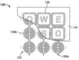
图6A和图6B分别为应用于按钮型促动器中的厚度模式换能器和电极图案的顶视图;6A and 6B are top views of thickness mode transducers and electrode patterns applied to button-type actuators, respectively;
图7示出采用图6A和图6B的按钮型促动器阵列的键区的顶部剖视图;Figure 7 shows a top cross-sectional view of a keypad employing the button-type actuator array of Figures 6A and 6B;
图8示出用于在人手形式的新颖的促动器中使用的厚度模式换能器的顶视图;Figure 8 shows a top view of a thickness mode transducer for use in a novel actuator in the form of a human hand;
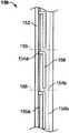
图9示出呈连续条带配置的厚度模式换能器的顶视图;Figure 9 shows a top view of a thickness mode transducer in a continuous strip configuration;
图10示出应用于垫片型促动器的厚度模式换能器的顶视图;Figure 10 shows a top view of a thickness mode transducer applied to a shim type actuator;
图11A至图11D是采用各种类型的垫片型促动器的触摸屏的截面图;11A to 11D are cross-sectional views of touch screens employing various types of pad-type actuators;
图12A至图12C分别为采用本发明的厚度模式促动器的提升阀机构的无源状态(passive state)和有源状态(active state)的截面图;12A to 12C are cross-sectional views of the passive state (passive state) and active state (active state) of the poppet valve mechanism employing the thickness mode actuator of the present invention, respectively;
图13A和图13B分别为采用本发明的厚度模式促动器的膜片型流体泵的无源状态和有源状态的截面图;13A and 13B are cross-sectional views of a passive state and an active state, respectively, of a diaphragm type fluid pump adopting the thickness mode actuator of the present invention;
图14A和图14B为采用本发明的厚度模式促动器的另一膜片型泵的截面图,其中泵分别经历排放冲程和压缩冲程;14A and 14B are cross-sectional views of another diaphragm-type pump employing the thickness mode actuator of the present invention, wherein the pump undergoes a discharge stroke and a compression stroke, respectively;
图15A和图15B为采用本发明的厚度模式促动器的蠕动泵实施例的截面图;15A and 15B are cross-sectional views of an embodiment of a peristaltic pump employing the thickness mode actuator of the present invention;
图16A和图16B是分别处于无源模式和有源模式的、采用本发明的厚度模式促动器的线性制动机构的截面图;16A and 16B are cross-sectional views of a linear braking mechanism employing the thickness mode actuator of the present invention in passive mode and active mode, respectively;
图17A和图17B为分别处于无源模式和有源模式的、采用本发明的厚度模式促动器的旋转式制动或离合机构的截面图;以及17A and 17B are cross-sectional views of a rotary braking or clutching mechanism employing the thickness mode actuator of the present invention in passive and active modes, respectively; and
图18A和图18B是本发明的厚度模式换能器的另一实施例的截面图,其中换能器的有源区域和无源区域的相对位置与上述实施例相反。18A and 18B are cross-sectional views of another embodiment of the thickness mode transducer of the present invention, in which the relative positions of the active region and the passive region of the transducer are reversed from the above embodiment.
从附图所示的本发明设想到本发明的变型。Variations of the invention are envisaged from the invention shown in the drawings.
具体实施方式Detailed ways
现将参看附图详细地描述本发明的装置、系统和方法。The apparatus, system and method of the present invention will now be described in detail with reference to the accompanying drawings.
参看图1A和图1B,提供根据本发明的一个实施例的用于将电能转换成机械能的表面变形EAP促动器10的示意图。促动器10包括EAP换能器12,该EAP换能器12具有薄弹性体介电聚合物层14和分别在电介质14的顶表面和底表面的部分上附连到介质14的顶部电极16a和底部电极16b。换能器12的包括电介质和至少两个电极的部分在本文中被称作有源区域。本发明的换能器中的任一个换能器可具有一个或多个有源区域。Referring to FIGS. 1A and 1B , a schematic illustration of a surface
当跨相反电荷的电极16a、16b施加电压差时,相反的电极彼此吸引,从而压缩之间的介电聚合物层14的部分。随着电极16a、16b被拉得更靠近(沿着Z轴),在它们之间的介电层14的部分由于其在平面方向(沿着x轴和y轴)扩展而变得更薄。对于不可压缩的聚合物,即,那些在应力下具有基本上恒定体积的聚合物,或者以别的方式保持在框架或类似物中的可压缩的聚合物,这种作用使得在有源区域(即,由电极覆盖的区域)之外,特别是沿周边地围绕有源区域的边缘(即,紧接地围绕)的柔顺的(compliant)介电材料在厚度方向(正交于由换能器膜限定的平面)移位或者凸出至平面外(out-of-plane)。这种凸出产生介电表面特征24a-d。虽然平面外表面特征24被示出相对地局限在有源区域,这种到平面外并非总是如图所示是局限的。在某些情况下,如果聚合物被预应变,那么表面特征24a-b分布于介电材料的非有源部分的表面区域上。When a voltage difference is applied across the oppositely charged
为了放大本换能器的表面特征的竖直轮廓和/或可视性,可选的无源层可被添加到换能器膜结构的一侧或两侧,其中无源层覆盖EAP膜表面区域的全部或一部分。在图1A和图1B的促动器实施例中,顶部无源层18a和底部无源层18b分别附连到EAP膜12的顶侧和底侧。促动器12的激活和因此形成的介电层12的表面特征17a-d由于添加的无源层18a、18b的厚度而被放大,如由图1B中的参考标记26a-d所示。To amplify the vertical profile and/or visibility of the surface features of the present transducer, an optional passive layer can be added to one or both sides of the transducer membrane structure, where the passive layer covers the EAP membrane surface all or part of the area. In the actuator embodiment of FIGS. 1A and 1B , a top
除了提高的聚合物/无源层表面特征26a-d之外,EAP膜12可被配置成使得一个或两个电极16a、16b被压在介电层厚度之下。因此,在激励EAP膜12且因此产生介电材料14偏转后,被压下的电极或其部分提供电极表面特征。电极16a、16c可被图案化或设计成产生定制的换能器膜表面特征,其可包括聚合物表面特征、电极表面特征和/或无源层表面特征。In addition to the enhanced polymer/passive layer surface features 26a-d, the
在图1A和图1B的促动器实施例10中,提供一个或多个结构20a、20b来便于耦接在柔顺无源平板(slab)与刚性机械结构之间的工作且引导促动器的工作输出。此处,顶部结构20a(其可呈平台、棒、杠杆、杆等形式)充当输出构件,而底部结构20b用于将促动器10耦接到固定或刚性的结构22,诸如地面。这些输出结构无需为离散部件,而是可与促动器预计要驱动的结构集成或成整体。结构20a、20b也用于限定由无源层18a、18b形成的表面特征26a-d的周边或形状。在图示实施例中,虽然聚合的促动器堆产生了促动器的非有源部分的厚度增加,如图1B所示,在激励时由促动器经历的高度净变化Δh为负。In the
本发明的EAP换能器可具有任何合适构造以提供所需厚度模式促动。举例而言,多于一个EAP膜层可用于制造换能器以用于更复杂的应用,诸如有集成感测能力的键盘按键,其中额外的EAP膜层可用作电容传感器。The EAP transducers of the present invention may have any suitable configuration to provide the desired thickness mode actuation. For example, more than one EAP film layer can be used to make transducers for more complex applications, such as keyboard keys with integrated sensing capabilities, where additional EAP film layers can be used as capacitive sensors.
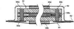
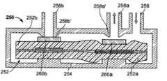
图2A示出根据本发明采用具有双EAP膜层34的堆叠的换能器32的促动器30。双层包括两个介电弹性体膜,其中顶膜34a分别夹在顶部电极34b与底部电极34c之间且底膜36a分别夹在顶部电极36b与底部电极36c之间。提供成对的导电迹线或层(通常被称作“母线”)以将电极耦接到高电压和电源的接地侧(后者未图示)。母线定位于各自的EAP膜的“非有源”部分(即,其中顶部电极和底部电极并不重叠的部分)上。顶部母线42a和底部母线42b分别定位于介电层34a的顶侧和底侧上且顶部母线44a和底部母线44b分别定位于介电层36a的顶侧和底侧上。电介质34a的顶部电极34b和电介质36a的底部电极36c,即两个朝向外的电极,通过导电弹性体通孔68a(在图2B中示出)由母线42a和44a的相互耦接而共同被偏振,导电弹性体通孔68a的形成在下文中参看图3A至图3D更详细地描述。电介质34a的底部电极34c和电介质36a的顶部电极36b,即两个朝向内的电极,也通过导电弹性体通孔68b(在图2B中示出)由母线42b和44b的相互耦接而共同被偏振。灌注材料66a、66b用于密封通孔68a、68b。当操作促动器时,当施加电压时,每个电极对的相反的电极吸引在一起。出于安全目的,接地电极可放置于堆的外侧上以便在任何尖锐的物体到达高电压电极之前使之接地,从而排除了电击危险。两个EAP膜层可由膜对膜粘合剂40b粘附在一起。粘合剂层可选地包括无源或平板层以提高性能。顶部无源层或平板50a和底部无源层52b由粘合剂层40a和粘合剂层40c而粘附到换能器结构。输出杆46a、46b可分别各自地(respectfully)由粘合剂层48a、48b耦接到顶部无源层和底部无源层。FIG. 2A shows an
本发明的促动器可采用任何合适数量的换能器层,其中层的数量可为偶数或奇数。在后一种构造中,可使用一个或多个共用接地电极和母线。此外,在安全性不成问题的情况下,高电压电极可定位于换能器堆的外侧上以更好地适应特定应用。Actuators of the present invention may employ any suitable number of transducer layers, where the number of layers may be even or odd. In the latter configuration, one or more common ground electrodes and bus bars may be used. Furthermore, where safety is not an issue, high voltage electrodes can be positioned on the outside of the transducer stack to better suit specific applications.
为了进行操作,促动器30必须电耦接到电源和控制电子器件(均未图示)。此可由促动器上或PCB上的电迹线或电线或将高电压和接地通孔68a、68b耦接到电源的或柔性连接器62或中间连接的来实现。促动器30可被包装于保护屏障材料中以密封它避免潮湿和环境污染物。此处,保护性屏障包括顶部覆盖件60和底部覆盖件64,其优选地绕PCB/柔性连接器62密封以保护促动器避免外力和应变和/或环境暴露。在某些实施例中,保护性屏障是不可渗透的以提供气密的密封。覆盖件可具有略微刚性的形式以屏蔽促动器30避免物理损坏或可为柔顺的以允许用于促动器30的促动位移的空间。在一个具体实施例中,顶部覆盖件60由成型箔制成且底部覆盖件64由柔顺的箔制成,或反之亦然,然后两个覆盖件被热密封到板/连接器62。也可使用许多其它包装材料,诸如金属化聚合物膜、PVDC、阿克拉(Aclar)、苯乙烯或烯属共聚物(styrenic or olefinic copolymer)、聚酯和聚烯烃类(polyolefins)。柔顺材料用于覆盖一个或多个输出结构,此处为杆46b,其平移(translate)促动器输出。In order to operate, the
本发明的堆叠的促动器/换能器结构(诸如刚刚描述的促动器30)的导电部件/层,由穿过堆叠结构而形成的电通孔(图2B中的68a和68b)共同耦接。图3至图5示出用于形成通孔的本发明的各种方法。The conductive components/layers of the stacked actuator/transducer structures of the present invention, such as the
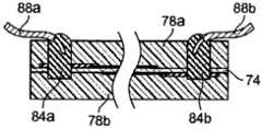
将参看图3A至图3D来描述用于图2B的促动器30中的类型的导电通孔的形成。在将促动器70(此处,由单个膜换能器构成,具有放置于介电层74的非有源部分的相对侧上的径向(diametrically)定位的母线76a、76b,一起夹在无源层78a、78b之间)层压到PCB/柔性连接器72之前或之后,堆叠的换能器/促动器结构70穿过其总厚度到PCB 72激光钻孔80以形成通孔82a、82b,如图3B所示。也可使用用于形成通孔的其它方法,诸如机械钻孔、冲孔、制模、穿孔和核化。然后由任何合适的分配方法来利用导电材料(例如在硅酮中的碳粒子)填充通孔,诸如通过注入,如图3C所示。然后,如图3D所示,导电的填充的通孔84a、84b可选地被灌注任何兼容的非导电材料,例如,硅酮,以电隔离通孔的暴露端。可替换地,可将非导电带子放置于暴露的通孔上。The formation of conductive vias of the type used in
可作为PCB或柔性连接器的替代使用标准电布线以将促动器耦接到电源和电子器件。利用这些实施例,形成到电源的电通孔和电连接的各种步骤在图4A至图4D中示出,其中与图3A至图3D中的部件和步骤相同的部件和步骤具有相同的附图标记。此处,如图4A所示,通孔82a、82b仅需在促动器厚度内钻出如此深度,使得到达母线84a、84b的程度。通孔然后被填充导电材料,如图4B所示,之后,将引线88a、88b插入于沉积的导电材料内,如图4C所示。导电填充的通孔和引线然后可被灌注覆盖,如图4D所示。Standard electrical wiring may be used instead of a PCB or flexible connector to couple the actuator to the power supply and electronics. Utilizing these embodiments, the various steps of forming electrical vias and electrical connections to the power source are shown in FIGS. 4A-4D , where the same components and steps as those in FIGS. Figure marker. Here, as shown in Figure 4A, the through
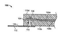
图5示出在本发明的换能器内提供导电通孔的另一方式。换能器100具有介电膜,其包括介电层104,介电层104具有夹在电极106a、106b之间的部分,而电极106a、106b依次被夹在无源聚合物层110a、110b之间。导电母线108设于EAP膜的非有源区域上。手动地或以其它方式,将具有尖锐的配置的导电接触件114通过换能器一侧钻入到穿透母线材料108的深度。导电迹线116从尖锐的接触件114的暴露端沿着PCB/柔性连接器112延伸。这种形成通孔的方法是特别高效的,因为其去除了以下步骤:钻出通孔;填充通孔,将导线放置于通孔中且灌注通孔。Figure 5 shows another way of providing conductive vias in the transducer of the present invention. The
本发明的厚度模式EAP换能器可用于具有合适构造和表面特征样式的多种促动器应用。图6至图10示出示范性厚度模式换能器/促动器应用。The thickness mode EAP transducers of the present invention can be used in a variety of actuator applications with suitable configurations and surface feature patterns. 6-10 illustrate exemplary thickness mode transducer/actuator applications.
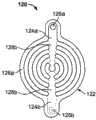
图6A示出具有圆形构造的厚度模式换能器120,其对于用于触知或触觉反馈应用中的按钮促动器是理想的,其中使用者物理地接触装置,例如,键盘、触摸屏、电话等。换能器20由薄弹性体介电聚合物层122和顶部电极图案124a和底部电极图案124b(以虚线示出底部电极图案)形成,在图6B中以隔离视图最佳地示出。电极图案124中每一个都提供具有形成同心图案的多个相对延伸的指状部127的柄部125。两个电极的柄在圆形介电层122的相对侧上彼此径向地被定位,其中它们的各自的指状部彼此并列对准以产生图6A所示的图案。虽然在此实施例中相对的电极图案相同且彼此对称,设想到其它实施例,其中相对的电极图案在形状和/或它们所占据的表面积的数量方面不对称。其中换能器材料的两个电极材料没有重叠的部分限定换能器的非有源部分128a、128b。电接触件126a、126b设于两个电极柄部中每一个电极柄部的基部以将换能器电耦接到电源和控制电子器件(均未图示)。当换能器被激活时,相对的电极指状物被吸引在一起,从而压缩在它们之间的介电材料122,其中换能器的非有源部分128a、128b凸出以如期望的那样形成绕按钮周边和/或在按钮内部的表面特征。FIG. 6A shows a
按钮促动器可呈单个输入或接触表面的形式或者可以具有多个接触表面的阵列格式来提供。当构造为阵列形式时,图6A的按钮换能器理想地用于键区促动器130,如图7所示,用于多种使用者接口装置,例如计算机键盘、电话、计算器等。换能器阵列132包括互连的电极图案的顶部阵列136a和电极图案的底部阵列136b(以虚线示出),其中两个阵列彼此相对以产生所描述的带有有源部分和非有源部分的图6A的同心换能器图案。键盘结构可呈在换能器阵列132顶部的无源层134的形式。无源层134可具有其自己的表面特征,诸如键盘边界138,其可在无源状态凸起以使得使用者能在触觉上对准他/她的手指与各自的键区,和/或进一步地在激活时放大相应按钮的周边的凸出。当按压健时,按键位于其上的各自的换能器被激活,造成厚度模式如上文所述那样地凸出,以提供返回到使用者的触觉感知。可以此方式提供任意数量的换能器且将该任意数量的换能器间隔开以适应正在所用的键区134的类型和大小。用于这些换能器阵列的制造技术的实例公开于在2008年6月27日提交且名称为“ELECTROACTIVE POLYMER TRANSDUCERS FOR SENSORYFEEDBACK APPLICATIONS”的美国专利申请第12/163,554号中,该专利申请以其全文引用的方式结合到本文中。Button actuators may be provided in the form of a single input or contact surface or may be provided in an array format with multiple contact surfaces. When configured in an array, the button transducers of FIG. 6A are ideal for use with
熟悉本领域的技术人员应了解本发明的厚度模式换能器无需对称且可采取任何构造和形状。本换能器可用于任何可想象的新颖的应用中,诸如图8所示的新颖的手形装置140。提供呈人手形式的介电材料142,其具有呈类似手形状的顶部电极图案144a和底部电极图案144b(以虚线示出下面的图案)。电极图案中的每一个电极图案分别电耦接到母线146a、146b,而母线146a、146b依次电耦接到电源和控制电子器件(均未图示)。此处,相对的电极图案彼此对准或在彼此的顶部上而非插置,从而形成交替的有源和非有源区域。因此,作为总体地在仅图案的内边缘和外边缘上形成凸起的表面特征的替代,在整个手形轮廓上(即,在非有源区域上)提供凸起的表面特征。应当注意的是在此示范性应用中的表面特征可提供视觉反馈而非触觉反馈。设想到视觉反馈可由着色、反射性材料等来增强。Those skilled in the art will appreciate that the thickness mode transducers of the present invention need not be symmetrical and may take any configuration and shape. The present transducer may be used in any imaginable novel application, such as the novel hand device 140 shown in FIG. 8 . A dielectric material 142 in the form of a human hand is provided having a top electrode pattern 144a and a bottom electrode pattern 144b in a hand-like shape (lower pattern shown in dashed lines). Each of the electrode patterns is electrically coupled to a bus bar 146a, 146b, respectively, which in turn is electrically coupled to power and control electronics (both not shown). Here, opposing electrode patterns are aligned with or on top of each other rather than interposed, thereby forming alternating active and non-active regions. Thus, instead of forming raised surface features generally on only the inner and outer edges of the pattern, raised surface features are provided over the entire hand contour (ie, on the non-active area). It should be noted that the surface features in this exemplary application may provide visual rather than tactile feedback. It is contemplated that visual feedback may be enhanced by coloring, reflective materials, and the like.
本发明的换能器膜可通过常用的基于卷材(web-based)的制造技术而高效地大量生产,特别是在换能器电极图案均匀或重复的情况下。如图9所示,可以连续条带格式提供换能器膜150,所述连续条带具有沉积或形成于介电材料152的条带上的连续的顶部电母线156a和底部电母线156b。更通常地,厚度模式特征由电耦接到相应的母线156a、156b的顶部电极图案156a和底部电极图案154b所形成的离散(即,不连续)但重复的有源区158而限定;其大小、长度、形状和图案可为了特定应用而被定制。但设想到可以连续图案形式提供一个或多个有源区。电极和母线图案可由已知的基于卷材的制造技术形成,其中然后也通过已知技术切划各自的换能器,诸如通过沿着选定的切划线155来切割条带150。应当注意的是在沿着条带连续地提供有源区的情况下,需要以高精确度来切割条带以避免使电极短路(shorting the electrodes)。这些电极的切割端可能需要灌注或另外地可能被回蚀(etch back)以避免漏电流路的形成(tracking)问题。母线156a、156b的切割端子然后耦接到电源和/或控制器以便能够促动所形成的促动器。The transducer film of the present invention can be efficiently mass-produced by common web-based manufacturing techniques, especially if the transducer electrode pattern is uniform or repeated. As shown in FIG. 9 , the
在切划之前或之后,条带或切划下的条带部分,可与任意数量的其它换能器膜条带/条带部分堆叠以提供多层结构。堆叠结构然后可被层压和机械地耦接(如果需要这样的话)促动器的刚性机械部件,诸如输出杆或类似物。Before or after scribing, the strips, or diced strip portions, can be stacked with any number of other transducer film strips/strip portions to provide a multilayer structure. The stacked structure can then be laminated and mechanically coupled (if so desired) to a rigid mechanical part of the actuator, such as an output rod or the like.
图10示出本换能器的另一变型,其中,换能器160由介电材料162的条带形成,其中在条带的相对侧上的顶部电极164a和底部电极164b被布置成矩形图案,从而构成开放区域165。电极中的每一个电极分别端接于电母线166a、166b中,电母线166a、166b具有电接触点168a、168b用于耦接到电源和电子控制器件(均未图示)。跨封闭区域165延伸的无源层(未图示)可用于换能器膜的任一侧上,从而形成垫片配置,用于环境保护和输出杆(也未图示)的机械耦接。如所配置的那样,激活换能器产生沿着换能器条带的内周边和外周边169的表面特征和有源区域164a、164b的厚度减小。应当注意是垫片促动器无需为连续的单个促动器。也可以使用一个或多个离散的促动器来勾勒(line)出区域的周边,该区域可选地利用非有源柔顺的垫片材料密封。Figure 10 shows another variation of the present transducer, in which the transducer 160 is formed from a strip of
其它垫片型促动器公开于上文引用的美国专利申请第12/163,554号中。这些类型的促动器适合于传感器(例如,触觉或振动)反馈应用,诸如用于手持多媒体装置、医疗器械、业务亭或汽车仪表面板、玩具或其它新颖的产品等应用中的触摸传感器板,触摸板和触摸屏。Other shim-type actuators are disclosed in above-referenced US Patent Application Serial No. 12/163,554. These types of actuators are suitable for sensor (e.g., tactile or vibration) feedback applications, such as touch sensor pads used in applications such as handheld multimedia devices, medical equipment, kiosks or automotive dashboards, toys or other novelty products, Touchpad and touchscreen.
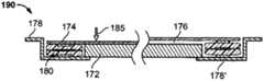
图11A至图11D是采用本发明的厚度模式促动器的变型的触摸屏的截面图,其中在四个附图中,相同的附图标记表示相似的部件。参看图11A,触摸屏装置170可包括触摸传感器板174且可选的液晶显示器(LCD)172,通常触摸传感器板174由玻璃或塑料材料制成。触摸传感器板174和液晶显示器(LCD)172被堆叠在一起且由EAP厚度模式促动器180间隔开,EAP厚度模式促动器180限定它们之间的开放空间176。总的堆叠结构由框架178结合在一起。促动器180包括由电极对184a、184b夹在中央的介电膜层182形成的换能器膜。而换能器膜依次夹在顶部和底部无源层186a、186b之间且进一步保持于输出结构对188a、188b之间,输出结构188a、188b分别机械地耦接到触摸板174和LCD 172。图11A的右侧示出当促动器为未激活时LCD与触摸板的相对位置,而图11A的左侧示出当促动器为激活时部件的相对位置,即,在使用者在箭头方向175按压触摸板174时。如从附图的左侧显而易见,当促动器180被激活时,电极184a、184b被吸引在一起,从而压缩在它们之间的介电膜182的部分,同时在有源区域之外的介电材料和无源层186a、186中形成表面特征,这些表面特征进一步被输出块188a、188b所造成的压缩力加强。因此,表面特征在与箭头175相反的方向在触摸板174上提供轻微力,其响应于按压触摸板而给予使用者触觉感知。11A to 11D are cross-sectional views of a touch screen employing a variation of the thickness mode actuator of the present invention, wherein like reference numerals represent similar components throughout the four figures. Referring to FIG. 11A , a touch screen device 170 may include a
图11B的触摸屏装置190具有类似于图11A的触摸屏装置的构造,且差别在于LCD 172完全在由矩形(或正方形等)形状的厚度模式促动器180构成的内部区域内。因此,当装置处于未激活状态(如在附图右侧所展示)时在LCD 172与触摸板174之间的间隔176显著地小于图11A的实施例中的情况,从而提供较低的轮廓设计。另外,促动器的底部输出结构188b直接搁置于框架178的后壁178′上。不论两个实施例之间的结构差别如何,装置190的功能类似于装置170,因为促动器表面特征响应于按压触摸板在与箭头185相反的方向中提供轻微触觉力。The
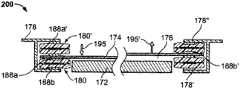
刚刚描述的两个触摸屏装置是单相装置,因为其在单个方向起作用。两个(或更多个)本垫片型促动器可被串联使用,用于产生两相(双向)触摸屏装置200,如图11C所示。装置200的构造类似于图11B的装置的构造,但添加了位于触摸板174顶部上的第二厚度模式促动器180′。两个促动器和触摸板174由框架178保持堆叠关系,框架178具有添加的向内延伸的顶部肩部178″。因此,触摸板174分别直接夹在促动器180、180′的最内部的输出块188a、188b′之间,而促动器180′的最外部的输出块188b、188a′分别支撑框架构件178′和178″。此封闭的垫片布置使得灰尘和碎屑不在空间176内的光学路径中。此处,附图的左侧示出处于有源状态的底部促动器180和处于无源状态的顶部促动器180′,其中使传感器板174在箭头195的方向上朝向LCD 172移动。相反,附图的右侧示出处于无源状态的底部促动器180且处于有源状态的顶部促动器180′,其中使传感器板174在箭头195′的方向上远离LCD 172移动。The two touch screen devices just described are single phase devices because they function in a single direction. Two (or more) of the present shim-type actuators can be used in series to create a two-phase (bi-directional)
图11D示出另一两相触摸传感器装置210,但具有定向为使电极正交于触摸传感器板的厚度模式条带促动器180对。此处,触摸板174的两相或双向移动在平面内,如由箭头205所示。为了能进行这种平面内移动,促动器180被定位成使得其EAP膜的平面正交于LCD 172和触摸板174的平面。为了维持这个位置,促动器180保持在框架178的侧壁202与触摸板174搁置于其上的内部框架构件206之间。虽然内部框架构件206附接到促动器180的输出块188a上,其和触摸板174相对于外部框架178是“浮动的”以为平面内或横向运动作好准备。这种构造提供相对紧凑的低轮廓设计,因为其排除了原本触摸板174的两相平面外运动所需的添加的空隙。两个促动器相反地工作用于两相运动。板174与支架206的组合的组件保持促动器条带180抵靠框架178的侧壁202轻微地压缩。当一个促动器为激活时,由于存储的压缩力其进一步压缩或变薄,而另一促动器则扩展。这使得板组件朝向有源促动器移动。板由于去激活第一促动器和激活第二促动器而在相反方向中移动。Figure 11D shows another two-phase
本换能器和促动器也可用于流体(即,液体、气体等)控制和移动应用中,包括阀和泵机构。图12A和图12B示出采用厚度模式促动器232的单向提升阀机构220。促动器安放于流体腔室234内,流体腔室234分别具有流体入口端口236和出口端口238。促动器232位于腔室234内使得其输出结构240与出口端口238对准。当促动器232处于无源状态时,如图12A所示,输出结构240抵靠限定阀座的出口端口的孔口238′被支撑。因此,阀具有常闭的配置。如图12B所示,促动器232的厚度模式操作在被激活时将输出结构240拉离阀座238′,从而允许腔室234内的流体通过出口端口238出来。The present transducers and actuators may also be used in fluid (ie, liquid, gas, etc.) control and movement applications, including valve and pump mechanisms. 12A and 12B illustrate a one-way
图12C示出具有流体腔室254的双向提升阀250,流体腔室254具有入口端口256和两个输出端口258a、258b,输出端口258a,258b具有相应的孔口258a′、258b′。包含在腔室内的促动器机构252包括两个可激活的部分252a、252b,各自分别具有输出结构260a、260b,分别与输出端口258a、258b对准。在图示实施例中,促动器部分252a是激活的,而促动器部分252b是未激活的,从而使流体交替通过两个出口端口流动。但是,若需要的话,这两个促动器部分可串联地被激活。应了解阀250可具有任意数量的出口端口促动器对,其中利用多个可激活部分的整体结构(如图所示)或利用多个在结构上离散的促动器实现促动功能。可串联地或独立地激活个别促动器或促动器部分,从而提供输出流动的任何组合。Figure 12C shows a
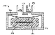
本促动器也适用于与膜片型泵一起使用。一种这样的膜片泵270在图13A和图13B中示出,其中流体腔室274分别具有入口端口276和出口端口278,具有止回阀机构来控制通过它的流体流动。厚度模式促动器272的输出结构280附接到膜片282的底侧上,其中膜片282在侧壁之间且跨腔室274的上端延伸。膜片由硬度足以在压缩压力下不弯曲或伸展的材料制成,例如,纤维加强的橡胶、硬质弹性体、填充的硅酮、薄金属膜等。激活和去激活促动器272使得膜片282分别远离和朝向入口端口和出口端口移动。在当膜片274朝向端口移动时在腔室274中造成的正压力的情况下,如图13A所示,使得出口止回阀278打开,允许流体从腔室排放。相反,在当膜片274远离端口移动时在腔室274中形成的负压力的情况下,如图13B所示,使得入口止回阀278打开,造成流体进入到腔室。This actuator is also suitable for use with diaphragm type pumps. One
图14A和图14B示出采用厚度模式多促动器机构276的另一膜片型泵。促动器具有三个可激活的部分276a-c(但可具有更多或更少的部分),其中外部两个部分276a、276c分别相对于流体腔室292的入口-出口端口274a、274b对准。膜片298在其底侧耦接到促动器部分的相应输出结构300a-c。为了从腔室292排放流体,通过激活外部促动器296a、296c打开一个或两个端口294a、294b,如图14A所示。相反,去激活外部促动器同时激活中央促动器296b,如图14B所示,则闭合两个阀端口同时也起动泵(priming the pump)用于下一排放冲程。膜片板298可以采用多种材料以便于提升阀密封,举例而言,膜可由金属箔制成且在阀区域上带有橡胶涂层。14A and 14B illustrate another diaphragm-type pump employing a thickness-
本发明的多相线性促动器机构也非常适用于与蠕动泵一起使用,诸如图15A和图15B的泵310。泵310包括具有基部312a和顶部部分或覆盖件312b的腔室或管道(其可具有任何合适的截面形状,诸如圆柱形、矩形、正方形等)。厚度模式促动器机构318此处被图示为具有四个可激活的部分,通过输出或安装结构314a而从基部312a偏移。相对的输出结构314b耦接到膜片316底侧。由结构314a、31b的偏移提供的间隔为非有源部分的厚度模式凸出和促动器条带318的有源部分的压缩作好准备。通过顺序地激活和去激活促动器318的各个有源部分来使流体在膜片316与顶部覆盖件312b之间线性地移动。可通过控制有源部分的开关速率来改变流量。可选地,固定膜片322可安装到顶部覆盖件312b的底侧来便于通过限定于两个膜片之间的通路320的流体流动动力学或提供一次性流体路径(其中促动器和壳体为非一次性的)。The polyphase linear actuator mechanism of the present invention is also well suited for use with peristaltic pumps, such as
图15B示出具有简化设计的另一蠕动泵330,其中去除了图15A的蠕动泵的一个或多个膜片和顶部输出结构。因此,促动器318的顶部无源层324采取先前膜片316的功能,其中流体流过在无源层与顶部覆盖件或312b之间的间隔326。FIG. 15B shows another
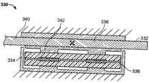
本厚度模式促动器也非常适用于制动器/离合器应用。图16A和图16B示出成比例线性制动系统330,其中可移动的构件332(诸如用于熟知的杆轴承布置的那些)可在接地结构338与制动机构334之间的间隔内线性地平移。制动器包括定位于壳体334内的厚度模式促动器机构336,壳体334也被接地。取决于构件332的表面积和阻止其移动所需的断裂力(breaking force),促动器336可具有一个或多个有源区域(即,此处采用两个有源区域)。对于最大断裂力(以及最大空隙),所有有源区域被同时激活/去激活。在无源状态,如图16A所示,促动器的输出板342处于闭合或延伸位置,从而将构件332夹持为抵靠接地垫338。在有源状态,如图16B所示,输出板342打开或退回到壳体334内,提供用于构件332线性移动的空隙。This thickness mode actuator is also well suited for brake/clutch applications. FIGS. 16A and 16B illustrate a proportional
图17A和图17B示出旋转式的制动系统350,其具有旋转盘352,旋转盘352具有盘元件352a和轴向轴杆352b。在壳体354内成堆叠关系地安装制动促动器356a、356b。盘352分别定位于朝向内的输出构件或制动或离合器垫358a、35b之间的间隔内。当促动器356a、356b为非有源且在其最高轮廓时,如图17A所示,使得它们向下夹持并阻止盘352的旋转。当促动器为有源的且处于压缩状态时,盘352被松开且允许移动穿过其。施加到盘352a的制动力的量可通过激活两个促动器之一或者串联地激活它们两者而成比例,但以降低的电压进行激活,以减小它们相应的输出移位。Figures 17A and 17B show a
迄今为止所描述的换能器/促动器实施例具有耦接到EAP换能器膜的有源区(即,包括重叠电极的区域)和非有源区的一个或读个无源层。在换能器/促动器也采用刚性输出结构的情况下,该结构定位于无源层的驻留在有源区域上方的区域上。另外,这些实施例的有源/可激活的区域相对于非有源区域被定位于中央。本发明还包括其它换能器/促动器配置。举例而言,一个或多个无源层可仅覆盖有源区或仅覆盖非有源区。此外,EAP膜的非有源区可相对于有源区定位于中央。The transducer/actuator embodiments described so far have one or more passive layers coupled to the active region (ie, the region comprising the overlapping electrodes) and the non-active region of the EAP transducer membrane. Where the transducer/actuator also employs a rigid output structure, this structure is positioned on the area of the passive layer that resides above the active area. Additionally, the active/activatable regions of these embodiments are centrally located relative to the non-active regions. The invention also includes other transducer/actuator configurations. For example, one or more passive layers may cover only active regions or only non-active regions. Additionally, the non-active region of the EAP film may be centrally located relative to the active region.
图18A和18B示出非有源区域相对于一个或多个有源区定位于内部或中央的一种变型,即,EAP膜的中央部分无重叠电极。厚度模式促动器360包括EAP换能器膜,EAP换能器膜包括夹在电极层364a、354b之间的介电层362,其中膜的中央部分365是无源的且无电极材料。EAP膜由顶部框架构件366a和底部框架构件366b中的至少一个保持拉紧或伸展状况,其中顶部框架构件366a和底部框架构件366b共同提供夹头(cartridge)配置。无源层368a、368b覆盖膜的无源部分365的顶侧和底侧中的至少一侧,其中可选的刚性约束件或输出构件370a、370b分别安装于无源层368a、368b上。在EAP由夹头框架366约束于其周边的情况下,当被激活(参看图18B)时,EAP膜的压缩使得膜材料向内收缩,如由箭头367a、367b所示,而非如同上述促动器实施例那样地向外。压缩的EAP膜碰撞无源材料368a、368b,使得其直径减小且其高度增加。这种配置变化分别对输出构件370a、370b施加向外的力。如同先前所述的促动器实施例,无源耦接的膜促动器可提供为多个、呈堆叠或平面关系以提供多相促动和/或增加促动器的输出力和/或冲程。Figures 18A and 18B show a variation in which the non-active region is positioned internally or centrally relative to the active region(s), ie, the central portion of the EAP film has no overlapping electrodes. The
可通过对介电膜和/或无源材料进行预应变而提高性能。促动器可用作按键或按钮装置且可与诸如膜开关的传感器装置堆叠或集成。底部输出构件或底部电极可用于向膜开关提供足够的压力来完成该电路或者如果底部输出构件具有导电层,则可直接完成该电路。多个促动器可以成阵列地用于诸如键区或键盘的应用。Performance can be enhanced by pre-straining the dielectric film and/or passive materials. The actuator can be used as a key or button device and can be stacked or integrated with a sensor device such as a membrane switch. The bottom output member or bottom electrode can be used to provide sufficient pressure to the membrane switch to complete the circuit or, if the bottom output member has a conductive layer, the circuit can be completed directly. Multiple actuators may be used in arrays for applications such as keypads or keyboards.
在美国专利申请公告第2005/0157893号中公开的各种介电弹性体和电极材料适用于与本发明的厚度模式换能器一起使用。一般而言,介电弹性体包括任何基本上绝缘的柔顺的聚合物,诸如硅酮橡胶或丙烯(acrylic),其响应于静电力而变形或其变形导致电场变化。在设计或选择适当聚合物时,可考虑最佳的材料、物理和化学性质。这些性质可通过明智地选择单体(monomer)(包括任何侧链(sidechain))、添加剂、交联程度、结晶度、分子量(molecular)等来制作。Various dielectric elastomers and electrode materials disclosed in US Patent Application Publication No. 2005/0157893 are suitable for use with the thickness mode transducer of the present invention. In general, dielectric elastomers include any substantially insulating, compliant polymer, such as silicone rubber or acrylic, which deforms in response to electrostatic forces or whose deformation results in a change in electric field. When designing or selecting an appropriate polymer, optimal material, physical and chemical properties can be considered. These properties can be crafted through judicious selection of monomers (including any sidechains), additives, degree of crosslinking, crystallinity, molecular weight, etc.
本文所述且适合于使用的电极包括:结构化电极,其包括金属迹线和电荷分配层;纹理化电极;导电脂,诸如碳脂或银脂;胶体悬浮液;高纵横比导电材料,诸如导电炭黑、碳原纤维(fibril)、碳纳米管、石墨烯(graphene)和金属纳米管和离子导电材料混合物。电极可由柔顺材料制成,诸如弹性体基体(matrix),其包含碳或其它导电微粒。本发明也可以采用金属和半非柔性电极。Electrodes described herein and suitable for use include: structured electrodes comprising metal traces and charge distribution layers; textured electrodes; conductive greases such as carbon or silver greases; colloidal suspensions; high aspect ratio conductive materials such as Conductive carbon black, carbon fibril (fibril), carbon nanotubes, graphene (graphene) and metal nanotubes and ion conductive material mixture. The electrodes may be made of a compliant material such as an elastomeric matrix containing carbon or other conductive particles. Metallic and semi-inflexible electrodes can also be used with the present invention.
用于本换能器中的示范性无源层材料包括但不限于例如硅酮、苯乙烯或烯属共聚物、聚氨酯、丙烯酸酯、橡胶、软聚合物、软弹性体(胶)、软聚合物泡沫或聚合物/凝胶混合物。选择一个或多个无源层和介电层的相对弹性和厚度以实现所期望的输出(例如,预期表面特征的净厚度或薄度),其中那个输出响应可被设计为线性的(例如,当被激活时,与介电层厚度成比例地放大无源层厚度)或者非线性的(例如,无源和介电层以变化的速率变得更薄或更厚)。Exemplary passive layer materials for use in the present transducer include, but are not limited to, silicone, styrene or olefinic copolymers, polyurethane, acrylate, rubber, soft polymer, soft elastomer (glue), soft polymer biofoam or polymer/gel blends. The relative elasticity and thickness of the one or more passive and dielectric layers are selected to achieve a desired output (e.g., net thickness or thinness of desired surface features), where that output response can be designed to be linear (e.g., When activated, the passive layer thickness is amplified proportionally to the dielectric layer thickness) or non-linearly (eg, the passive and dielectric layers become thinner or thicker at varying rates).
关于方法,本方法可包括与所描述的装置的使用相关联的机械和/或活动中的每一个。因此,暗示所描述的装置的使用的方法形成本发明的一部分。其它方法可集中于这些装置的制造。With respect to methods, the methods may include each of the machinery and/or activities associated with use of the described apparatus. Accordingly, methods of use suggesting the use of the described apparatus form part of the invention. Other methods may focus on the fabrication of these devices.
关于本发明的其它细节,可在相关技术领域技术人员的水平内采用材料和替代物相关的配置。关于本发明的基于方法的方面,就常用或逻辑上采用的额外行为而言,同样如此。此外,尽管已经参考可选地合并了各种特征的若干实例对本发明展开描述,但本发明并不限于如根据本发明的每个变型所构想的所描述或指示的情形。在不偏离本发明的真实精神和范围的情况下,可对本发明做出各种变化且可替代等效物(无论是否在本文中陈述或者为了简要起见而未包括)。所示出的任意数量的个别零件或子组件可集成于其设计中。这些变化或其它变化可以由组件设计原理来进行或引导。With regard to other details of the present invention, configurations relating to materials and substitutions may be employed within the level of a person skilled in the relevant art. The same is true with respect to method-based aspects of the invention insofar as additional acts are commonly or logically employed. Furthermore, although the invention has been described with reference to several examples optionally incorporating various features, the invention is not limited to what is described or indicated as conceived according to each variant of the invention. Various changes may be made to the invention and equivalents (whether or not stated herein or not included for the sake of brevity) may be substituted without departing from the true spirit and scope of the invention. Any number of individual parts or subassemblies shown may be integrated into its design. These or other changes may be made or guided by component design principles.
而且,设想到所描述的本发明变型的任何可选特征可独立地陈述和要求被保护,或者与本文所描述的特征中的一个或多个特征组合。对于单数物品的提及包括存在复数个相同物品的可能。更具体而言,如本文所用和权利要求中所用的那样,单数形式“一”、“所述”和“该”包括复数个参考物,除非另外具体地陈述。换言之,这些冠词的使用考虑到在上面的说明以及下面的权利要求中存在那种物品中的“至少一个”。还应当注意是权利要求可以被撰写为排除任何可选的元件。因此,这个陈述意在用作与权利要求元件的引用有关的排他性术语如“仅仅”、“仅”及类似词的使用或“否定”限制的使用的在先基础。在不使用这些排他性术语的情况下,权利要求中的术语“包括”应当考虑到包括任何附加的元件—与在权利要求中列举了给定数量的元件或是特征的添加可以认作改变了权利要求中阐述的元件的属性无关。另外说明,除非本文中特别限定,否则本文中使用的所有技术和科学术语都被给定尽可能地普遍理解的含义,同时保持权利要求的有效性。Furthermore, it is contemplated that any optional feature of the described inventive variants may be stated and claimed independently, or in combination with one or more of the features described herein. Reference to an item in the singular includes the possibility that there may be a plurality of the same item. More specifically, as used herein and in the claims, the singular forms "a", "the", and "the" include plural references unless specifically stated otherwise. In other words, use of these articles contemplates the presence of "at least one" of that item in the description above as well as the claims below. It should also be noted that the claims may be drafted to exclude any optional elements. Accordingly, this statement is intended to serve as a prior basis for the use of exclusive terminology such as "only," "only," and similar words or the use of a "negative" limitation in relation to the recitation of claim elements. In the absence of these exclusive terms, the term "comprising" in a claim should be considered to include any additional elements—additions to a given number of elements or features recited in a claim are deemed to alter the claim. The properties of the elements stated in the requirements are irrelevant. Also stated, unless otherwise defined herein, all technical and scientific terms used herein are to be given as commonly understood meanings as possible while maintaining claim validity.
总之,本发明的宽度不受到所提供实例的限制。In general, the breadth of the invention is not limited by the examples provided.
Claims (44)
Applications Claiming Priority (5)
| Application Number | Priority Date | Filing Date | Title |
|---|---|---|---|
| US11164808P | 2008-11-05 | 2008-11-05 | |
| US61/111648 | 2008-11-05 | ||
| US12/358,142US8222799B2 (en) | 2008-11-05 | 2009-01-22 | Surface deformation electroactive polymer transducers |
| US12/358142 | 2009-01-22 | ||
| PCT/US2009/063441WO2010054115A1 (en) | 2008-11-05 | 2009-11-05 | Surface deformation electroactive polymer transducers |
Publications (1)
| Publication Number | Publication Date |
|---|---|
| CN102272959Atrue CN102272959A (en) | 2011-12-07 |
Family
ID=42130526
Family Applications (1)
| Application Number | Title | Priority Date | Filing Date |
|---|---|---|---|
| CN2009801543356APendingCN102272959A (en) | 2008-11-05 | 2009-11-05 | Surface deformation electroactive polymer transducer |
Country Status (9)
| Country | Link |
|---|---|
| US (1) | US8222799B2 (en) |
| EP (1) | EP2347459B1 (en) |
| JP (1) | JP5684713B2 (en) |
| KR (2) | KR101535045B1 (en) |
| CN (1) | CN102272959A (en) |
| CA (1) | CA2742410A1 (en) |
| MX (1) | MX2011004695A (en) |
| TW (1) | TWI527070B (en) |
| WO (1) | WO2010054115A1 (en) |
Cited By (10)
| Publication number | Priority date | Publication date | Assignee | Title |
|---|---|---|---|---|
| CN104049787A (en)* | 2013-03-14 | 2014-09-17 | 联想(北京)有限公司 | Electronic equipment and control method |
| CN104916773A (en)* | 2014-03-14 | 2015-09-16 | 中国科学院苏州纳米技术与纳米仿生研究所 | Electro-deformation thin film array and preparation method and application thereof |
| WO2017177729A1 (en)* | 2016-04-14 | 2017-10-19 | 京东方科技集团股份有限公司 | Apparatus and system for simulating light guide plate, backlight module, and test method |
| CN107646000A (en)* | 2015-05-27 | 2018-01-30 | 罗伯特·博世有限公司 | Devices for varying pedal resistance, brake systems |
| US10115884B2 (en) | 2015-01-23 | 2018-10-30 | Boe Technology Group Co., Ltd. | Flexible display |
| CN109962643A (en)* | 2019-02-01 | 2019-07-02 | 杭州电子科技大学 | Method for reducing internal resistance of electret-based energy harvester and energy harvester |
| CN110419020A (en)* | 2017-03-29 | 2019-11-05 | 住友理工株式会社 | Vibration reminder device |
| CN111201577A (en)* | 2017-10-11 | 2020-05-26 | 瑞士单浮筒系泊公司 | Electroactive polymer device and method for manufacturing such a device |
| CN111403431A (en)* | 2019-01-02 | 2020-07-10 | 京东方科技集团股份有限公司 | Flexible body and method for controlling deformation of flexible body |
| CN117111358A (en)* | 2023-08-30 | 2023-11-24 | 长沙惠科光电有限公司 | Dimming component, edge-type backlight module, display device and dimming method thereof |
Families Citing this family (174)
| Publication number | Priority date | Publication date | Assignee | Title |
|---|---|---|---|---|
| US7952261B2 (en) | 2007-06-29 | 2011-05-31 | Bayer Materialscience Ag | Electroactive polymer transducers for sensory feedback applications |
| US9370640B2 (en) | 2007-09-12 | 2016-06-21 | Novasentis, Inc. | Steerable medical guide wire device |
| US8154527B2 (en) | 2008-01-04 | 2012-04-10 | Tactus Technology | User interface system |
| US9423875B2 (en) | 2008-01-04 | 2016-08-23 | Tactus Technology, Inc. | Dynamic tactile interface with exhibiting optical dispersion characteristics |
| US9588683B2 (en) | 2008-01-04 | 2017-03-07 | Tactus Technology, Inc. | Dynamic tactile interface |
| US8704790B2 (en) | 2010-10-20 | 2014-04-22 | Tactus Technology, Inc. | User interface system |
| US9128525B2 (en) | 2008-01-04 | 2015-09-08 | Tactus Technology, Inc. | Dynamic tactile interface |
| US8547339B2 (en) | 2008-01-04 | 2013-10-01 | Tactus Technology, Inc. | System and methods for raised touch screens |
| US9612659B2 (en) | 2008-01-04 | 2017-04-04 | Tactus Technology, Inc. | User interface system |
| US8922510B2 (en) | 2008-01-04 | 2014-12-30 | Tactus Technology, Inc. | User interface system |
| US9552065B2 (en) | 2008-01-04 | 2017-01-24 | Tactus Technology, Inc. | Dynamic tactile interface |
| US8553005B2 (en) | 2008-01-04 | 2013-10-08 | Tactus Technology, Inc. | User interface system |
| US9274612B2 (en) | 2008-01-04 | 2016-03-01 | Tactus Technology, Inc. | User interface system |
| US8570295B2 (en) | 2008-01-04 | 2013-10-29 | Tactus Technology, Inc. | User interface system |
| US9298261B2 (en) | 2008-01-04 | 2016-03-29 | Tactus Technology, Inc. | Method for actuating a tactile interface layer |
| US9430074B2 (en) | 2008-01-04 | 2016-08-30 | Tactus Technology, Inc. | Dynamic tactile interface |
| US9557915B2 (en) | 2008-01-04 | 2017-01-31 | Tactus Technology, Inc. | Dynamic tactile interface |
| US8243038B2 (en) | 2009-07-03 | 2012-08-14 | Tactus Technologies | Method for adjusting the user interface of a device |
| US9720501B2 (en) | 2008-01-04 | 2017-08-01 | Tactus Technology, Inc. | Dynamic tactile interface |
| US8947383B2 (en) | 2008-01-04 | 2015-02-03 | Tactus Technology, Inc. | User interface system and method |
| US8456438B2 (en) | 2008-01-04 | 2013-06-04 | Tactus Technology, Inc. | User interface system |
| US20160187981A1 (en) | 2008-01-04 | 2016-06-30 | Tactus Technology, Inc. | Manual fluid actuator |
| US9063627B2 (en) | 2008-01-04 | 2015-06-23 | Tactus Technology, Inc. | User interface and methods |
| US9052790B2 (en) | 2008-01-04 | 2015-06-09 | Tactus Technology, Inc. | User interface and methods |
| US9588684B2 (en) | 2009-01-05 | 2017-03-07 | Tactus Technology, Inc. | Tactile interface for a computing device |
| US8760413B2 (en)* | 2009-01-08 | 2014-06-24 | Synaptics Incorporated | Tactile surface |
| EP2239793A1 (en) | 2009-04-11 | 2010-10-13 | Bayer MaterialScience AG | Electrically switchable polymer film structure and use thereof |
| US8915151B2 (en)* | 2009-06-05 | 2014-12-23 | Sungkyunkwan University Foundation For Corporate Collaboration | Active skin for conformable tactile interface |
| CN101923417B (en)* | 2009-06-10 | 2013-06-05 | 鸿富锦精密工业(深圳)有限公司 | Touch type input device |
| WO2011003113A1 (en) | 2009-07-03 | 2011-01-06 | Tactus Technology | User interface enhancement system |
| US10164135B2 (en)* | 2009-08-07 | 2018-12-25 | Guardian Glass, LLC | Electronic device including graphene-based layer(s), and/or method or making the same |
| US8569935B1 (en)* | 2009-09-14 | 2013-10-29 | Tomasz Andrzej Kosierkiewicz | Piezoelectric shoe insert |
| US8624839B2 (en) | 2009-10-15 | 2014-01-07 | Synaptics Incorporated | Support-surface apparatus to impart tactile feedback |
| US10068728B2 (en) | 2009-10-15 | 2018-09-04 | Synaptics Incorporated | Touchpad with capacitive force sensing |
| KR101113897B1 (en) | 2009-12-07 | 2012-02-29 | 한국과학기술원 | Solenoid System Using Spiral Transparant Material of Conductivity, Apparatus Providing Passive Haptic Feedback Using the Same, Touchpad Using the Same and Control Method |
| WO2011087816A1 (en) | 2009-12-21 | 2011-07-21 | Tactus Technology | User interface system |
| CN102782617B (en) | 2009-12-21 | 2015-10-07 | 泰克图斯科技公司 | User interface system |
| US9298262B2 (en) | 2010-01-05 | 2016-03-29 | Tactus Technology, Inc. | Dynamic tactile interface |
| US8619035B2 (en) | 2010-02-10 | 2013-12-31 | Tactus Technology, Inc. | Method for assisting user input to a device |
| WO2011112984A1 (en) | 2010-03-11 | 2011-09-15 | Tactus Technology | User interface system |
| WO2011113883A1 (en) | 2010-03-17 | 2011-09-22 | Bayer Materialscience Ag | Statistic analysis of audio signals for generation of discernable feedback |
| US20110242041A1 (en)* | 2010-04-01 | 2011-10-06 | Nokia Corporation | Method and Apparatus for Performing a Function |
| WO2011133604A1 (en) | 2010-04-19 | 2011-10-27 | Tactus Technology | User interface system |
| WO2011133605A1 (en) | 2010-04-19 | 2011-10-27 | Tactus Technology | Method of actuating a tactile interface layer |
| EP2614542B1 (en)* | 2010-09-09 | 2017-07-19 | Philips Lighting Holding B.V. | Adjustable reflector based on an electroactive polymer actuator |
| US20120068938A1 (en)* | 2010-09-16 | 2012-03-22 | Research In Motion Limited | Electronic device with touch-sensitive display |
| CN103124946B (en) | 2010-10-20 | 2016-06-29 | 泰克图斯科技公司 | User interface system and method |
| DE102010042690A1 (en)* | 2010-10-20 | 2012-04-26 | Bayerische Motoren Werke Aktiengesellschaft | Input device for controlling an electronic device |
| US8704647B2 (en)* | 2010-12-21 | 2014-04-22 | Electronics And Telecommunications Research Institute | Haptic feedback case for electronic equipment |
| JP5814774B2 (en)* | 2010-12-22 | 2015-11-17 | 日本碍子株式会社 | Composite substrate and method for manufacturing composite substrate |
| DE102010056562B4 (en) | 2010-12-30 | 2018-10-11 | Snaptrack, Inc. | Electroacoustic component and method for producing the electroacoustic component |
| DE102010056572B4 (en)* | 2010-12-30 | 2018-12-27 | Snaptrack, Inc. | Electronic component and method for producing the electronic component |
| US8847890B2 (en) | 2011-01-04 | 2014-09-30 | Synaptics Incorporated | Leveled touchsurface with planar translational responsiveness to vertical travel |
| US8912458B2 (en) | 2011-01-04 | 2014-12-16 | Synaptics Incorporated | Touchsurface with level and planar translational travel responsiveness |
| US9553254B2 (en) | 2011-03-01 | 2017-01-24 | Parker-Hannifin Corporation | Automated manufacturing processes for producing deformable polymer devices and films |
| EP2689284A4 (en) | 2011-03-22 | 2014-08-20 | Bayer Ip Gmbh | Electroactive polymer actuator lenticular system |
| US9122325B2 (en)* | 2011-05-10 | 2015-09-01 | Northwestern University | Touch interface device and method for applying controllable shear forces to a human appendage |
| US10108288B2 (en) | 2011-05-10 | 2018-10-23 | Northwestern University | Touch interface device and method for applying controllable shear forces to a human appendage |
| WO2012177719A2 (en) | 2011-06-21 | 2012-12-27 | Northwestern University | Touch interface device and method for applying lateral forces on a human appendage |
| US8866774B2 (en)* | 2011-06-29 | 2014-10-21 | The Board Of Trustees Of The Leland Stanford Junior University | Low power touch screen overlays for providing tactile feedback |
| WO2013017143A1 (en)* | 2011-08-04 | 2013-02-07 | L&P Swiss Holding Ag | Diaphragm pump for a seat adjusting device and seat adjusting device |
| TW201342788A (en)* | 2011-12-09 | 2013-10-16 | Bayer Materialscience Ag | Techniques for fabricating an actuator element |
| US9220635B2 (en) | 2011-12-22 | 2015-12-29 | Douglas D. Churovich | Tactile pattern music generator and player |
| EP2828901B1 (en) | 2012-03-21 | 2017-01-04 | Parker Hannifin Corporation | Roll-to-roll manufacturing processes for producing self-healing electroactive polymer devices |
| WO2013154720A1 (en) | 2012-04-13 | 2013-10-17 | Tk Holdings Inc. | Pressure sensor including a pressure sensitive material for use with control systems and methods of using the same |
| US9761790B2 (en) | 2012-06-18 | 2017-09-12 | Parker-Hannifin Corporation | Stretch frame for stretching process |
| US9705068B2 (en) | 2012-06-19 | 2017-07-11 | Novasentis, Inc. | Ultra-thin inertial actuator |
| US9183710B2 (en) | 2012-08-03 | 2015-11-10 | Novasentis, Inc. | Localized multimodal electromechanical polymer transducers |
| US9218927B2 (en) | 2012-08-06 | 2015-12-22 | Synaptics Incorporated | Touchsurface assembly with level and planar translational responsiveness via a buckling elastic component |
| US9040851B2 (en) | 2012-08-06 | 2015-05-26 | Synaptics Incorporated | Keycap assembly with an interactive spring mechanism |
| WO2014025786A1 (en) | 2012-08-06 | 2014-02-13 | Synaptics Incorporated | Touchsurface assembly utilizing magnetically enabled hinge |
| US9177733B2 (en) | 2012-08-06 | 2015-11-03 | Synaptics Incorporated | Touchsurface assemblies with linkages |
| EP2885868A4 (en)* | 2012-08-16 | 2016-04-13 | Bayer Ip Gmbh | Rolled and compliant dielectric elastomer actuators |
| WO2014043664A1 (en)* | 2012-09-17 | 2014-03-20 | Tk Holdings Inc. | Single layer force sensor |
| US9351900B2 (en) | 2012-09-17 | 2016-05-31 | President And Fellows Of Harvard College | Soft exosuit for assistance with human motion |
| WO2014047656A2 (en) | 2012-09-24 | 2014-03-27 | Tactus Technology, Inc. | Dynamic tactile interface and methods |
| US9405417B2 (en) | 2012-09-24 | 2016-08-02 | Tactus Technology, Inc. | Dynamic tactile interface and methods |
| WO2014066576A1 (en) | 2012-10-24 | 2014-05-01 | Bayer Intellectual Property Gmbh | Polymer diode |
| WO2014074554A2 (en)* | 2012-11-06 | 2014-05-15 | Bayer Intellectual Property Gmbh | Stacked actuator apparatus, system, and method |
| US9170650B2 (en) | 2012-11-21 | 2015-10-27 | Novasentis, Inc. | EMP actuators for deformable surface and keyboard application |
| EP2923211B1 (en)* | 2012-11-21 | 2025-03-19 | KONRAD GmbH | Method and device for testing a workpiece |
| US9164586B2 (en)* | 2012-11-21 | 2015-10-20 | Novasentis, Inc. | Haptic system with localized response |
| US9357312B2 (en) | 2012-11-21 | 2016-05-31 | Novasentis, Inc. | System of audio speakers implemented using EMP actuators |
| US9053617B2 (en) | 2012-11-21 | 2015-06-09 | Novasentis, Inc. | Systems including electromechanical polymer sensors and actuators |
| EP2929574A2 (en) | 2012-12-07 | 2015-10-14 | Bayer Materialscience AG | Electroactive polymer actuated aperture |
| US10105504B2 (en) | 2012-12-18 | 2018-10-23 | Koninklijke Philips N.V. | EAP-driven air pump for patient interfaces |
| US10088936B2 (en) | 2013-01-07 | 2018-10-02 | Novasentis, Inc. | Thin profile user interface device and method providing localized haptic response |
| WO2014107677A1 (en) | 2013-01-07 | 2014-07-10 | Novasentis, Inc. | Method and localized haptic response system provided on an interior-facing surface of a housing of an electronic device |
| US9913321B2 (en)* | 2013-01-25 | 2018-03-06 | Energyield, Llc | Energy harvesting container |
| TW201502859A (en) | 2013-01-28 | 2015-01-16 | Bayer Materialscience Ag | Electroactive polymer actuators and feedback system therefor |
| US9384919B2 (en) | 2013-03-14 | 2016-07-05 | Synaptics Incorporated | Touchsurface assembly having key guides formed in a sheet metal component |
| TW201447217A (en) | 2013-03-15 | 2014-12-16 | Bayer Materialscience Ag | Electroactive polymer actuated air flow thermal management module |
| WO2014160757A2 (en) | 2013-03-26 | 2014-10-02 | Bayer Materialscience Ag | Independent tunig of audio devices employing electroactive polymer actuators |
| US9213372B2 (en) | 2013-04-19 | 2015-12-15 | Synaptics Incorporated | Retractable keyboard keys |
| JP6851197B2 (en) | 2013-05-30 | 2021-03-31 | ティーケー ホールディングス インク.Tk Holdings Inc. | Multidimensional trackpad |
| CN108670195B (en) | 2013-05-31 | 2022-05-10 | 哈佛大学校长及研究员协会 | Soft Robotic Armor for Assisting Human Movement |
| US9557813B2 (en) | 2013-06-28 | 2017-01-31 | Tactus Technology, Inc. | Method for reducing perceived optical distortion |
| US10125758B2 (en) | 2013-08-30 | 2018-11-13 | Novasentis, Inc. | Electromechanical polymer pumps |
| US9507468B2 (en) | 2013-08-30 | 2016-11-29 | Novasentis, Inc. | Electromechanical polymer-based sensor |
| US9833596B2 (en) | 2013-08-30 | 2017-12-05 | Novasentis, Inc. | Catheter having a steerable tip |
| WO2015054362A1 (en) | 2013-10-08 | 2015-04-16 | Tk Holdings Inc. | Force-based touch interface with ingrated multi-sensory feedback |
| US9666391B2 (en) | 2013-10-22 | 2017-05-30 | Novasentis, Inc. | Retractable snap domes |
| US11324655B2 (en) | 2013-12-09 | 2022-05-10 | Trustees Of Boston University | Assistive flexible suits, flexible suit systems, and methods for making and control thereof to assist human mobility |
| WO2015120186A1 (en) | 2014-02-05 | 2015-08-13 | President And Fellows Of Harvard College | Systems, methods, and devices for assisting walking for developmentally-delayed toddlers |
| EP3108510B1 (en)* | 2014-02-18 | 2018-12-26 | Parker Hannifin Corp | Electroactive polymer actuator with improved performance |
| EP3128963A4 (en) | 2014-04-10 | 2017-12-06 | President and Fellows of Harvard College | Orthopedic device including protruding members |
| DE102014005851B4 (en)* | 2014-04-22 | 2018-10-18 | Festo Ag & Co. Kg | Method and device for producing elastomer actuators |
| US9652946B2 (en) | 2014-05-02 | 2017-05-16 | Novasentis, Inc. | Hands-free, wearable vibration devices and method |
| US9576446B2 (en) | 2014-08-07 | 2017-02-21 | Novasentis, Inc. | Ultra-thin haptic switch with lighting |
| US9972768B2 (en) | 2014-08-15 | 2018-05-15 | Novasentis, Inc. | Actuator structure and method |
| KR20160031715A (en)* | 2014-09-15 | 2016-03-23 | 삼성전자주식회사 | Air current changeable full front blowing type air conditioner |
| US10434030B2 (en) | 2014-09-19 | 2019-10-08 | President And Fellows Of Harvard College | Soft exosuit for assistance with human motion |
| DE102014114212A1 (en)* | 2014-09-30 | 2016-03-31 | Bürkert Werke GmbH | diaphragm valve |
| US10466826B2 (en) | 2014-10-08 | 2019-11-05 | Joyson Safety Systems Acquisition Llc | Systems and methods for illuminating a track pad system |
| KR102533118B1 (en)* | 2014-12-17 | 2023-05-16 | 카버 싸이언티픽, 아이엔씨. | Entropic energy transfer methods and circuits |
| US20220241118A1 (en) | 2014-12-29 | 2022-08-04 | ElastiMed Ltd. | Methods and mechanisms for maintaining an electro-active polymer in a pre-stretch state and uses thereof |
| EP4284149A3 (en) | 2014-12-29 | 2024-03-06 | Elastimed Ltd. | Methods and mechanisms for maintaining an electro-active polymer in a pre-stretch state and uses thereof |
| JP6766152B2 (en) | 2014-12-29 | 2020-10-07 | エラスティメッド・リミテッドElastiMed Ltd. | Methods and Mechanisms for Maintaining Electroactive Polymers in Pre-Stretched State and Their Use |
| CN104613303B (en)* | 2015-01-16 | 2017-03-22 | 西北工业大学 | Controllable out-of-plane deformation unit based on electric active soft matter |
| JP6699119B2 (en)* | 2015-01-22 | 2020-05-27 | 株式会社リコー | Element and power generator |
| KR20170132198A (en) | 2015-03-09 | 2017-12-01 | 더 유니버시티 오브 브리티쉬 콜롬비아 | Apparatus and methods for providing tactile stimulus incorporating tri-layer actuators |
| KR101652029B1 (en)* | 2015-04-13 | 2016-08-30 | 주식회사 하이딥 | Pressure detection module and smartphone including the same |
| GB201511042D0 (en)* | 2015-06-23 | 2015-08-05 | Royal College Of Art And Kong Ming | Sensor device and method |
| US10543907B2 (en)* | 2015-07-06 | 2020-01-28 | California Institute Of Technology | Flow control technique by dielectric materials |
| DE102015214569B4 (en)* | 2015-07-31 | 2019-10-17 | Conti Temic Microelectronic Gmbh | Device for the pneumatic adjustment of a seat in a means of transport |
| US10145005B2 (en) | 2015-08-19 | 2018-12-04 | Guardian Glass, LLC | Techniques for low temperature direct graphene growth on glass |
| US10484793B1 (en) | 2015-08-25 | 2019-11-19 | Apple Inc. | Electronic devices with orientation sensing |
| RU2727067C2 (en)* | 2015-08-31 | 2020-07-17 | Конинклейке Филипс Н.В. | Converter for conversion of electric and/or radiation signal into movement or vice versa |
| KR101731173B1 (en)* | 2015-09-02 | 2017-04-28 | 한국과학기술원 | Capacitive type pressure sensor with porous dielectric layer |
| KR101859509B1 (en)* | 2015-09-15 | 2018-05-18 | 한국과학기술원 | Haptic display pannel for using wavelength and amplitude change of wrinkle pattern for generating various texture and method thereof |
| US9929485B2 (en)* | 2015-11-12 | 2018-03-27 | International Business Machines Corporation | Card edge connector using a set of electroactive polymers |
| WO2017110195A1 (en)* | 2015-12-25 | 2017-06-29 | 住友理工株式会社 | Tactile vibration presentation device |
| WO2017160751A1 (en) | 2016-03-13 | 2017-09-21 | President And Fellows Of Harvard College | Flexible members for anchoring to the body |
| CN109314127A (en) | 2016-06-13 | 2019-02-05 | 皇家飞利浦有限公司 | Actuator device and driving method comprising electroactive polymer actuator |
| EP3487666B1 (en) | 2016-07-22 | 2024-11-13 | President and Fellows of Harvard College | Controls optimization for wearable systems |
| KR102640240B1 (en)* | 2016-10-31 | 2024-02-22 | 엘지디스플레이 주식회사 | Contact sensitive device and display device including the same |
| US20180138831A1 (en)* | 2016-11-17 | 2018-05-17 | Immersion Corporation | Control of Contact Conditions For Static ESF |
| US10416768B2 (en)* | 2016-12-28 | 2019-09-17 | Immersion Corporation | Unitary sensor and haptic actuator |
| US11014804B2 (en) | 2017-03-14 | 2021-05-25 | President And Fellows Of Harvard College | Systems and methods for fabricating 3D soft microstructures |
| US10396272B2 (en)* | 2017-05-04 | 2019-08-27 | International Business Machines Corporation | Display distortion for alignment with a user gaze direction |
| GB2580810B (en)* | 2017-11-10 | 2021-06-09 | Aspen Pumps Ltd | Pumps |
| WO2019107309A1 (en)* | 2017-11-28 | 2019-06-06 | 正毅 千葉 | Dielectric elastomer drive sensor system and sheet |
| EP3759448B1 (en)* | 2018-03-01 | 2025-06-11 | Universität Basel Vizerektorat Forschung | Sensor with a dielectric elastomer transducer, corresponding utilization method and fabrication process of a dielectric elastomer transducer |
| KR102337975B1 (en)* | 2018-03-09 | 2021-12-10 | 가부시키가이샤 후지킨 | valve device |
| EP3544070A1 (en)* | 2018-03-21 | 2019-09-25 | Koninklijke Philips N.V. | Actuator device and actuation method |
| US10962791B1 (en) | 2018-03-22 | 2021-03-30 | Facebook Technologies, Llc | Apparatuses, systems, and methods for fabricating ultra-thin adjustable lenses |
| US11245065B1 (en) | 2018-03-22 | 2022-02-08 | Facebook Technologies, Llc | Electroactive polymer devices, systems, and methods |
| US11048075B1 (en) | 2018-03-29 | 2021-06-29 | Facebook Technologies, Llc | Optical lens assemblies and related methods |
| KR102113508B1 (en) | 2018-07-12 | 2020-05-22 | 한국과학기술연구원 | Tactile Feedback Device |
| US10747332B2 (en)* | 2018-09-13 | 2020-08-18 | Apple Inc. | Flexible stabilized button input device |
| US11067200B2 (en)* | 2018-10-24 | 2021-07-20 | Toyota Motor Engineering & Manufacturing North America, Inc. | Self-healing microvalve |
| US11548261B2 (en) | 2018-10-24 | 2023-01-10 | Toyota Motor Engineering & Manufacturing North America, Inc. | Structure with selectively variable stiffness |
| US10946535B2 (en) | 2018-10-25 | 2021-03-16 | Toyota Motor Engineering & Manufacturing North America, Inc. | Earthworm-like motion of soft bodied structure |
| US11088635B2 (en) | 2018-10-25 | 2021-08-10 | Toyota Motor Engineering & Manufacturing North America, Inc. | Actuator with sealable edge region |
| US11041576B2 (en) | 2018-10-25 | 2021-06-22 | Toyota Motor Engineering & Manufacturing North America, Inc. | Actuator with static activated position |
| US11081975B2 (en) | 2018-10-25 | 2021-08-03 | Toyota Motor Engineering & Manufacturing North America, Inc. | Somersaulting motion of soft bodied structure |
| US11498270B2 (en) | 2018-11-21 | 2022-11-15 | Toyota Motor Engineering & Manufacturing North America, Inc. | Programmable matter |
| US10749448B2 (en)* | 2018-11-30 | 2020-08-18 | Facebook Technologies, Llc | Engineered loading response in electroactive polymer devices having structured nanovoids |
| US11195506B2 (en) | 2018-12-03 | 2021-12-07 | Toyota Motor Engineering & Manufacturing North America, Inc. | Sound-modulating windows |
| US10859101B2 (en) | 2018-12-10 | 2020-12-08 | Toyota Motor Engineering & Manufacturing North America, Inc. | Soft-bodied actuator with pinched configuration |
| US11066016B2 (en) | 2018-12-18 | 2021-07-20 | Toyota Motor Engineering & Manufacturing North America, Inc. | Adjusting vehicle mirrors |
| US11479308B2 (en) | 2019-01-09 | 2022-10-25 | Toyota Motor Engineering & Manufacturing North America, Inc. | Active vehicle interface for crosswind management |
| US11473567B2 (en) | 2019-02-07 | 2022-10-18 | Toyota Motor Engineering & Manufacturing North America, Inc. | Programmable surface |
| JP2020167656A (en)* | 2019-03-28 | 2020-10-08 | 住友理工株式会社 | Transducer device and transducer system |
| US11411166B2 (en)* | 2019-05-17 | 2022-08-09 | International Business Machines Corporation | Conductive particle interconnect switch |
| US11411165B2 (en) | 2019-05-17 | 2022-08-09 | International Business Machines Corporation | Conductive particle interconnect switch |
| WO2021070809A1 (en)* | 2019-10-08 | 2021-04-15 | ソニー株式会社 | Actuator, method of manufacturing same, driving device, and electronic equipment |
| US11422629B2 (en) | 2019-12-30 | 2022-08-23 | Joyson Safety Systems Acquisition Llc | Systems and methods for intelligent waveform interruption |
| US11370496B2 (en)* | 2020-01-31 | 2022-06-28 | Toyota Motor Engineering & Manufacturing North America, Inc. | Programmable texture surfaces having artificial muscles |
| DE102020103474A1 (en)* | 2020-02-11 | 2021-08-12 | Bürkert Werke GmbH & Co. KG | Valve actuator and valve |
| DE102020203208A1 (en)* | 2020-03-12 | 2021-09-16 | Fraunhofer-Gesellschaft zur Förderung der angewandten Forschung eingetragener Verein | Electromechanical converter and its use |
| LU102398B1 (en)* | 2021-01-11 | 2022-07-11 | Innovationlab Gmbh | Sensor device |
| US11598331B2 (en) | 2021-02-24 | 2023-03-07 | Toyota Motor Engineering & Manufacturing North America, Inc. | Electroactive polymer actuator for multi-stage pump |
| US11941974B2 (en)* | 2022-07-20 | 2024-03-26 | Tdk Corporation | Systems, methods, and devices for haptic feedback |
Family Cites Families (45)
| Publication number | Priority date | Publication date | Assignee | Title |
|---|---|---|---|---|
| US6376971B1 (en)* | 1997-02-07 | 2002-04-23 | Sri International | Electroactive polymer electrodes |
| US6882086B2 (en)* | 2001-05-22 | 2005-04-19 | Sri International | Variable stiffness electroactive polymer systems |
| US6543110B1 (en)* | 1997-02-07 | 2003-04-08 | Sri International | Electroactive polymer fabrication |
| US6781284B1 (en)* | 1997-02-07 | 2004-08-24 | Sri International | Electroactive polymer transducers and actuators |
| US6586859B2 (en)* | 2000-04-05 | 2003-07-01 | Sri International | Electroactive polymer animated devices |
| WO1998035529A2 (en)* | 1997-02-07 | 1998-08-13 | Sri International | Elastomeric dielectric polymer film sonic actuator |
| US6891317B2 (en)* | 2001-05-22 | 2005-05-10 | Sri International | Rolled electroactive polymers |
| US7320457B2 (en)* | 1997-02-07 | 2008-01-22 | Sri International | Electroactive polymer devices for controlling fluid flow |
| US6545384B1 (en)* | 1997-02-07 | 2003-04-08 | Sri International | Electroactive polymer devices |
| US7052594B2 (en)* | 2002-01-31 | 2006-05-30 | Sri International | Devices and methods for controlling fluid flow using elastic sheet deflection |
| US6809462B2 (en)* | 2000-04-05 | 2004-10-26 | Sri International | Electroactive polymer sensors |
| US6812624B1 (en)* | 1999-07-20 | 2004-11-02 | Sri International | Electroactive polymers |
| US6806621B2 (en)* | 2001-03-02 | 2004-10-19 | Sri International | Electroactive polymer rotary motors |
| US6664718B2 (en)* | 2000-02-09 | 2003-12-16 | Sri International | Monolithic electroactive polymers |
| US7608989B2 (en)* | 1999-07-20 | 2009-10-27 | Sri International | Compliant electroactive polymer transducers for sonic applications |
| DE60037433T2 (en)* | 1999-07-20 | 2008-12-04 | Sri International, Menlo Park | Electroactive polymer generators |
| US6911764B2 (en)* | 2000-02-09 | 2005-06-28 | Sri International | Energy efficient electroactive polymers and electroactive polymer devices |
| WO2001063738A2 (en)* | 2000-02-23 | 2001-08-30 | Sri International | Electroactive polymer thermal electric generators |
| WO2001065615A2 (en)* | 2000-02-23 | 2001-09-07 | Sri International | Biologically powered electroactive polymer generators |
| US6879318B1 (en)* | 2000-10-06 | 2005-04-12 | Industrial Technology Research Institute | Touch screen mounting assembly for LCD panel and method for fabrication |
| US7166953B2 (en)* | 2001-03-02 | 2007-01-23 | Jon Heim | Electroactive polymer rotary clutch motors |
| US7233097B2 (en)* | 2001-05-22 | 2007-06-19 | Sri International | Rolled electroactive polymers |
| US6876135B2 (en)* | 2001-10-05 | 2005-04-05 | Sri International | Master/slave electroactive polymer systems |
| US6707236B2 (en)* | 2002-01-29 | 2004-03-16 | Sri International | Non-contact electroactive polymer electrodes |
| AU2003225913A1 (en)* | 2002-03-18 | 2003-10-08 | Roy David Kornbluh | Electroactive polymer devices for moving fluid |
| JP2004134216A (en)* | 2002-10-10 | 2004-04-30 | Hitachi Displays Ltd | Cathode ray tube |
| US7253735B2 (en) | 2003-03-24 | 2007-08-07 | Alien Technology Corporation | RFID tags and processes for producing RFID tags |
| JP5615479B2 (en)* | 2003-08-29 | 2014-10-29 | エスアールアイ インターナショナルSRI International | Pre-strain of electroactive polymer |
| DK1665880T3 (en)* | 2003-09-03 | 2013-02-25 | Stanford Res Inst Int | Electroactive surface deformation polymer transducers |
| US7449821B2 (en)* | 2005-03-02 | 2008-11-11 | Research Triangle Institute | Piezoelectric micromachined ultrasonic transducer with air-backed cavities |
| GB0504484D0 (en)* | 2005-03-03 | 2005-04-13 | Ultra Electronics Ltd | Haptic feedback device |
| US7915789B2 (en)* | 2005-03-21 | 2011-03-29 | Bayer Materialscience Ag | Electroactive polymer actuated lighting |
| US7521840B2 (en)* | 2005-03-21 | 2009-04-21 | Artificial Muscle, Inc. | High-performance electroactive polymer transducers |
| US7521847B2 (en)* | 2005-03-21 | 2009-04-21 | Artificial Muscle, Inc. | High-performance electroactive polymer transducers |
| US7595580B2 (en)* | 2005-03-21 | 2009-09-29 | Artificial Muscle, Inc. | Electroactive polymer actuated devices |
| US7626319B2 (en)* | 2005-03-21 | 2009-12-01 | Artificial Muscle, Inc. | Three-dimensional electroactive polymer actuated devices |
| US7750532B2 (en)* | 2005-03-21 | 2010-07-06 | Artificial Muscle, Inc. | Electroactive polymer actuated motors |
| US20070200457A1 (en)* | 2006-02-24 | 2007-08-30 | Heim Jonathan R | High-speed acrylic electroactive polymer transducers |
| US20070230222A1 (en)* | 2006-03-31 | 2007-10-04 | Drabing Richard B | Power circuitry for high-frequency applications |
| US7394282B2 (en)* | 2006-06-28 | 2008-07-01 | Intel Corporation | Dynamic transmission line termination |
| EP1919073B1 (en)* | 2006-11-03 | 2012-08-08 | Danfoss A/S | A direct acting capacitive transducer |
| US7492076B2 (en)* | 2006-12-29 | 2009-02-17 | Artificial Muscle, Inc. | Electroactive polymer transducers biased for increased output |
| US9823833B2 (en)* | 2007-06-05 | 2017-11-21 | Immersion Corporation | Method and apparatus for haptic enabled flexible touch sensitive surface |
| US7952261B2 (en)* | 2007-06-29 | 2011-05-31 | Bayer Materialscience Ag | Electroactive polymer transducers for sensory feedback applications |
| CN102272702A (en)* | 2008-11-04 | 2011-12-07 | 拜尔材料科学股份公司 | Electroactive polymer transducers for tactile feedback devices |
- 2009
- 2009-01-22USUS12/358,142patent/US8222799B2/enactiveActive
- 2009-11-05JPJP2011535671Apatent/JP5684713B2/enactiveActive
- 2009-11-05EPEP09825433.7Apatent/EP2347459B1/enactiveActive
- 2009-11-05KRKR1020147014204Apatent/KR101535045B1/ennot_activeExpired - Fee Related
- 2009-11-05TWTW098137649Apatent/TWI527070B/enactive
- 2009-11-05KRKR1020117010238Apatent/KR20110097764A/ennot_activeCeased
- 2009-11-05CACA2742410Apatent/CA2742410A1/ennot_activeAbandoned
- 2009-11-05MXMX2011004695Apatent/MX2011004695A/enactiveIP Right Grant
- 2009-11-05WOPCT/US2009/063441patent/WO2010054115A1/enactiveApplication Filing
- 2009-11-05CNCN2009801543356Apatent/CN102272959A/enactivePending
Cited By (17)
| Publication number | Priority date | Publication date | Assignee | Title |
|---|---|---|---|---|
| CN104049787A (en)* | 2013-03-14 | 2014-09-17 | 联想(北京)有限公司 | Electronic equipment and control method |
| US9535534B2 (en) | 2013-03-14 | 2017-01-03 | Lenovo (Beijing) Co., Ltd. | Electronic device and control method |
| CN104049787B (en)* | 2013-03-14 | 2017-03-29 | 联想(北京)有限公司 | A kind of electronic equipment and control method |
| CN104916773A (en)* | 2014-03-14 | 2015-09-16 | 中国科学院苏州纳米技术与纳米仿生研究所 | Electro-deformation thin film array and preparation method and application thereof |
| CN104916773B (en)* | 2014-03-14 | 2017-10-20 | 中国科学院苏州纳米技术与纳米仿生研究所 | Electrostrictive membrane array, its preparation method and application |
| US10115884B2 (en) | 2015-01-23 | 2018-10-30 | Boe Technology Group Co., Ltd. | Flexible display |
| CN107646000A (en)* | 2015-05-27 | 2018-01-30 | 罗伯特·博世有限公司 | Devices for varying pedal resistance, brake systems |
| CN107646000B (en)* | 2015-05-27 | 2020-07-31 | 罗伯特·博世有限公司 | Device for changing pedal resistance and brake system |
| WO2017177729A1 (en)* | 2016-04-14 | 2017-10-19 | 京东方科技集团股份有限公司 | Apparatus and system for simulating light guide plate, backlight module, and test method |
| US10353131B2 (en) | 2016-04-14 | 2019-07-16 | Boe Technology Group Co., Ltd. | Device, system, backlight module and test method for simulating light guide plate |
| CN110419020A (en)* | 2017-03-29 | 2019-11-05 | 住友理工株式会社 | Vibration reminder device |
| CN111201577A (en)* | 2017-10-11 | 2020-05-26 | 瑞士单浮筒系泊公司 | Electroactive polymer device and method for manufacturing such a device |
| CN111403431A (en)* | 2019-01-02 | 2020-07-10 | 京东方科技集团股份有限公司 | Flexible body and method for controlling deformation of flexible body |
| US11706992B2 (en) | 2019-01-02 | 2023-07-18 | Fuzhou Boe Optoelectronics Technology Co., Ltd. | Flexible body and method for controlling flexible body to deform |
| CN111403431B (en)* | 2019-01-02 | 2023-09-05 | 京东方科技集团股份有限公司 | Flexible body and method for controlling deformation of flexible body |
| CN109962643A (en)* | 2019-02-01 | 2019-07-02 | 杭州电子科技大学 | Method for reducing internal resistance of electret-based energy harvester and energy harvester |
| CN117111358A (en)* | 2023-08-30 | 2023-11-24 | 长沙惠科光电有限公司 | Dimming component, edge-type backlight module, display device and dimming method thereof |
Also Published As
| Publication number | Publication date |
|---|---|
| KR20110097764A (en) | 2011-08-31 |
| US8222799B2 (en) | 2012-07-17 |
| JP5684713B2 (en) | 2015-03-18 |
| EP2347459B1 (en) | 2017-08-23 |
| EP2347459A1 (en) | 2011-07-27 |
| KR101535045B1 (en) | 2015-07-09 |
| KR20140089389A (en) | 2014-07-14 |
| CA2742410A1 (en) | 2010-05-14 |
| EP2347459A4 (en) | 2014-11-19 |
| US20100109486A1 (en) | 2010-05-06 |
| JP2012508556A (en) | 2012-04-05 |
| TW201025376A (en) | 2010-07-01 |
| WO2010054115A1 (en) | 2010-05-14 |
| MX2011004695A (en) | 2011-05-30 |
| TWI527070B (en) | 2016-03-21 |
Similar Documents
| Publication | Publication Date | Title |
|---|---|---|
| EP2347459B1 (en) | Surface deformation electroactive polymer transducers | |
| US20130207793A1 (en) | Electroactive polymer transducers for tactile feedback devices | |
| US20120126959A1 (en) | Electroactive polymer transducers for tactile feedback devices | |
| JP2012508556A5 (en) | ||
| US20130044049A1 (en) | Electroactive polymer transducers for tactile feedback devices | |
| US20120206248A1 (en) | Flexure assemblies and fixtures for haptic feedback | |
| US20110128239A1 (en) | Electroactive polymer transducers for tactile feedback devices | |
| TW201126377A (en) | Electroactive polymer transducers for tactile feedback devices | |
| WO2023023095A1 (en) | System and method for an interaction surface with shape-changing tactile elements |
Legal Events
| Date | Code | Title | Description |
|---|---|---|---|
| C06 | Publication | ||
| PB01 | Publication | ||
| C10 | Entry into substantive examination | ||
| SE01 | Entry into force of request for substantive examination | ||
| C12 | Rejection of a patent application after its publication | ||
| RJ01 | Rejection of invention patent application after publication | Application publication date:20111207 |