CN102271621A - Orthotopic artificial bladder prosthesis - Google Patents
Orthotopic artificial bladder prosthesisDownload PDFInfo
- Publication number
- CN102271621A CN102271621ACN200980153977.4ACN200980153977ACN102271621ACN 102271621 ACN102271621 ACN 102271621ACN 200980153977 ACN200980153977 ACN 200980153977ACN 102271621 ACN102271621 ACN 102271621A
- Authority
- CN
- China
- Prior art keywords
- prosthesis
- membrane
- balloon
- coated
- hollow member
- Prior art date
- Legal status (The legal status is an assumption and is not a legal conclusion. Google has not performed a legal analysis and makes no representation as to the accuracy of the status listed.)
- Pending
Links
- 210000000626ureterAnatomy0.000claimsabstractdescription42
- 210000003708urethraAnatomy0.000claimsabstractdescription14
- 239000012528membraneSubstances0.000claimsdescription48
- OKTJSMMVPCPJKN-UHFFFAOYSA-NCarbonChemical compound[C]OKTJSMMVPCPJKN-UHFFFAOYSA-N0.000claimsdescription34
- 229910052799carbonInorganic materials0.000claimsdescription34
- 229920001296polysiloxanePolymers0.000claimsdescription20
- 230000000873masking effectEffects0.000claimsdescription18
- 238000000034methodMethods0.000claimsdescription12
- 238000011065in-situ storageMethods0.000claimsdescription11
- 238000004073vulcanizationMethods0.000claimsdescription7
- 239000000853adhesiveSubstances0.000claimsdescription5
- 230000001070adhesive effectEffects0.000claimsdescription5
- 238000000151depositionMethods0.000claimsdescription4
- 238000004519manufacturing processMethods0.000claimsdescription3
- 239000013464silicone adhesiveSubstances0.000claimsdescription3
- 229920002994synthetic fiberPolymers0.000claimsdescription3
- 239000012620biological materialSubstances0.000claims2
- 239000010410layerSubstances0.000description11
- 230000008569processEffects0.000description5
- 239000000560biocompatible materialSubstances0.000description2
- 230000008021depositionEffects0.000description2
- 230000017074necrotic cell deathEffects0.000description2
- 239000000523sampleSubstances0.000description2
- 229910001220stainless steelInorganic materials0.000description2
- 239000010935stainless steelSubstances0.000description2
- 210000002700urineAnatomy0.000description2
- 206010010356Congenital anomalyDiseases0.000description1
- 210000001015abdomenAnatomy0.000description1
- 239000002775capsuleSubstances0.000description1
- 239000011248coating agentSubstances0.000description1
- 238000000576coating methodMethods0.000description1
- 229920001577copolymerPolymers0.000description1
- 230000008878couplingEffects0.000description1
- 238000010168coupling processMethods0.000description1
- 238000005859coupling reactionMethods0.000description1
- 230000001419dependent effectEffects0.000description1
- -1dimethylsiloxaneChemical class0.000description1
- 201000010099diseaseDiseases0.000description1
- 208000037265diseases, disorders, signs and symptomsDiseases0.000description1
- 230000000694effectsEffects0.000description1
- 238000005516engineering processMethods0.000description1
- 230000006872improvementEffects0.000description1
- 238000003780insertionMethods0.000description1
- 230000037431insertionEffects0.000description1
- 239000007788liquidSubstances0.000description1
- 230000007246mechanismEffects0.000description1
- 229920002529medical grade siliconePolymers0.000description1
- 238000012986modificationMethods0.000description1
- 230000004048modificationEffects0.000description1
- 238000000465mouldingMethods0.000description1
- 230000001575pathological effectEffects0.000description1
- 239000002243precursorSubstances0.000description1
- 239000002296pyrolytic carbonSubstances0.000description1
- 229910052710siliconInorganic materials0.000description1
- 239000010703siliconSubstances0.000description1
- 239000002356single layerSubstances0.000description1
- 238000001356surgical procedureMethods0.000description1
Images


Classifications
- A—HUMAN NECESSITIES
- A61—MEDICAL OR VETERINARY SCIENCE; HYGIENE
- A61F—FILTERS IMPLANTABLE INTO BLOOD VESSELS; PROSTHESES; DEVICES PROVIDING PATENCY TO, OR PREVENTING COLLAPSING OF, TUBULAR STRUCTURES OF THE BODY, e.g. STENTS; ORTHOPAEDIC, NURSING OR CONTRACEPTIVE DEVICES; FOMENTATION; TREATMENT OR PROTECTION OF EYES OR EARS; BANDAGES, DRESSINGS OR ABSORBENT PADS; FIRST-AID KITS
- A61F2/00—Filters implantable into blood vessels; Prostheses, i.e. artificial substitutes or replacements for parts of the body; Appliances for connecting them with the body; Devices providing patency to, or preventing collapsing of, tubular structures of the body, e.g. stents
- A61F2/02—Prostheses implantable into the body
- A61F2/04—Hollow or tubular parts of organs, e.g. bladders, tracheae, bronchi or bile ducts
- A61F2/042—Urinary bladders
- A—HUMAN NECESSITIES
- A61—MEDICAL OR VETERINARY SCIENCE; HYGIENE
- A61F—FILTERS IMPLANTABLE INTO BLOOD VESSELS; PROSTHESES; DEVICES PROVIDING PATENCY TO, OR PREVENTING COLLAPSING OF, TUBULAR STRUCTURES OF THE BODY, e.g. STENTS; ORTHOPAEDIC, NURSING OR CONTRACEPTIVE DEVICES; FOMENTATION; TREATMENT OR PROTECTION OF EYES OR EARS; BANDAGES, DRESSINGS OR ABSORBENT PADS; FIRST-AID KITS
- A61F2/00—Filters implantable into blood vessels; Prostheses, i.e. artificial substitutes or replacements for parts of the body; Appliances for connecting them with the body; Devices providing patency to, or preventing collapsing of, tubular structures of the body, e.g. stents
- A61F2/95—Instruments specially adapted for placement or removal of stents or stent-grafts
- A61F2/958—Inflatable balloons for placing stents or stent-grafts
- A—HUMAN NECESSITIES
- A61—MEDICAL OR VETERINARY SCIENCE; HYGIENE
- A61L—METHODS OR APPARATUS FOR STERILISING MATERIALS OR OBJECTS IN GENERAL; DISINFECTION, STERILISATION OR DEODORISATION OF AIR; CHEMICAL ASPECTS OF BANDAGES, DRESSINGS, ABSORBENT PADS OR SURGICAL ARTICLES; MATERIALS FOR BANDAGES, DRESSINGS, ABSORBENT PADS OR SURGICAL ARTICLES
- A61L27/00—Materials for grafts or prostheses or for coating grafts or prostheses
- A61L27/28—Materials for coating prostheses
- A61L27/30—Inorganic materials
- A—HUMAN NECESSITIES
- A61—MEDICAL OR VETERINARY SCIENCE; HYGIENE
- A61F—FILTERS IMPLANTABLE INTO BLOOD VESSELS; PROSTHESES; DEVICES PROVIDING PATENCY TO, OR PREVENTING COLLAPSING OF, TUBULAR STRUCTURES OF THE BODY, e.g. STENTS; ORTHOPAEDIC, NURSING OR CONTRACEPTIVE DEVICES; FOMENTATION; TREATMENT OR PROTECTION OF EYES OR EARS; BANDAGES, DRESSINGS OR ABSORBENT PADS; FIRST-AID KITS
- A61F2/00—Filters implantable into blood vessels; Prostheses, i.e. artificial substitutes or replacements for parts of the body; Appliances for connecting them with the body; Devices providing patency to, or preventing collapsing of, tubular structures of the body, e.g. stents
- A61F2/02—Prostheses implantable into the body
- A61F2/04—Hollow or tubular parts of organs, e.g. bladders, tracheae, bronchi or bile ducts
- A61F2/06—Blood vessels
- A61F2/064—Blood vessels with special features to facilitate anastomotic coupling
Landscapes
- Health & Medical Sciences (AREA)
- Veterinary Medicine (AREA)
- Animal Behavior & Ethology (AREA)
- Public Health (AREA)
- Life Sciences & Earth Sciences (AREA)
- Oral & Maxillofacial Surgery (AREA)
- Transplantation (AREA)
- Engineering & Computer Science (AREA)
- Biomedical Technology (AREA)
- General Health & Medical Sciences (AREA)
- Heart & Thoracic Surgery (AREA)
- Cardiology (AREA)
- Vascular Medicine (AREA)
- Gastroenterology & Hepatology (AREA)
- Pulmonology (AREA)
- Chemical & Material Sciences (AREA)
- Urology & Nephrology (AREA)
- Medicinal Chemistry (AREA)
- Dermatology (AREA)
- Epidemiology (AREA)
- Inorganic Chemistry (AREA)
- Prostheses (AREA)
- Materials For Medical Uses (AREA)
Abstract
Description
Translated fromChinese技术领域technical field
本发明涉及一种原位人造膀胱假体(orthotopic artificial bladderprosthesis)。The invention relates to an orthotopic artificial bladder prosthesis.
背景技术Background technique
众所周知,当患者的膀胱受到损害它的正常功能的严重的不可治愈疾病影响时,用人造膀胱假体置换膀胱是合乎需要的。It is well known that replacement of the bladder with an artificial bladder prosthesis is desirable when a patient's bladder is affected by a serious incurable disease that impairs its normal function.
在为了解决该问题而开发的各种解决方案中,一种解决方案是如专利WO2007/039159中所述的那样用由柔性多层硅酮制造的可压缩膀胱置换天然膀胱,通过简单地挤压下腹来排空所述可压缩膀胱。该类型的假体通过使用缝线来提供输尿管和尿道与所述人造膀胱之间的连接。然而,用缝线缝合并不总是可行的,例如在输尿管和/或尿道由于先天性或病理性原因而被弱化和/或薄化的情况下。此外,使用缝线需要高超的手工技能并且在置换过程期间需要使用更多时间。Among the various solutions developed to solve this problem, one is the replacement of the natural bladder with a compressible bladder made of flexible multilayer silicone as described in patent WO2007/039159, by simply squeezing Lower the abdomen to empty the compressible bladder. This type of prosthesis provides a connection between the ureter and urethra and the artificial bladder by using sutures. However, suturing with sutures is not always possible, for example in cases where the ureter and/or urethra are weakened and/or thinned for congenital or pathological reasons. Furthermore, the use of sutures requires great manual skill and time-consuming use during the replacement procedure.
发明内容Contents of the invention
本发明的目的是通过提供一种原位人造膀胱假体来克服现有技术的缺陷,所述膀胱假体能够置换天然膀胱并且允许患者的生活质量显著改善。The aim of the present invention is to overcome the drawbacks of the prior art by providing an in situ artificial bladder prosthesis capable of replacing the natural bladder and allowing a significant improvement in the patient's quality of life.
本发明的另一个目的是提供这样一种原位人造膀胱假体,所述膀胱假体不需要使用缝线来将输尿管和/或尿道固定到所述人造膀胱,因此避免了组织坏死的风险。Another object of the present invention is to provide an in situ artificial bladder prosthesis which does not require the use of sutures to fix the ureters and/or urethra to the artificial bladder, thus avoiding the risk of tissue necrosis.
本发明的又一个目的是提供这样一种原位人造膀胱假体,所述膀胱假体容易生产。Yet another object of the present invention is to provide such an in situ artificial bladder prosthesis which is easy to produce.
这些目的根据具有在附带的独立权利要求1中所列出的特征的本发明来实现。These objects are achieved according to the invention having the features set out in the appended independent claim 1 .
本发明的有利实施例将在从属权利要求中一目了然。Advantageous embodiments of the invention will be apparent from the dependent claims.
根据本发明的原位人造膀胱假体包括由柔软且具有弹性的合成材料的多层式膜制造的封闭件或袋或气囊,所述多层式膜的内层不会由于尿液而性能退化,而外层适合于防止与周围组织粘连。所述原位假体还包括用于将输尿管连接到所述假体的至少两个孔和相同数量的中空构件,所述中空构件具有加宽圆形扁平底座和通过所述孔的管状部分,所述管状部分具有与输尿管的外径基本相同的内径,从而实现干涉配合而不需要使用粘合剂将输尿管固定在所述管状部分内部。然后将输尿管强制插入所述中空构件的所述管状部分内部而基本上不缩窄输尿管内腔。The in situ artificial bladder prosthesis according to the invention comprises a closure or bag or bladder made of a multilayer membrane of soft and elastic synthetic material, the inner layer of which is not degraded by urine , while the outer layer is adapted to prevent adhesion to surrounding tissue. said in situ prosthesis also comprises at least two holes for connecting ureters to said prosthesis and the same number of hollow members having a widened circular flat base and a tubular portion passing through said holes, The tubular portion has an inner diameter that is substantially the same as the outer diameter of the ureter, thereby achieving an interference fit without the need for adhesives to secure the ureter inside the tubular portion. The ureter is then forcibly inserted inside the tubular portion of the hollow member without substantially narrowing the lumen of the ureter.
附图说明Description of drawings
通过以下参考在附图中示出的本发明的纯示例性的、因此非限定性的实施例的详细描述,本发明的进一步的特征将变得更加清楚,在附图中:Further features of the invention will become clearer from the following detailed description with reference to purely exemplary, and therefore non-limiting, embodiments of the invention shown in the accompanying drawings, in which:
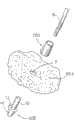
图1是原位人造膀胱假体的透视图,其中一输尿管被显示为借助于根据本发明的中空构件连接到所述假体,而其他的输尿管和尿道借助于根据现有技术的缝线连接到假体;Figure 1 is a perspective view of an in situ artificial bladder prosthesis, wherein one ureter is shown connected to said prosthesis by means of a hollow member according to the invention, while the other ureter and urethra are connected by means of sutures according to the prior art to the prosthesis;
图2是沿着图1的截面II-II获得的人造膀胱的一部分的放大横截面图;Figure 2 is an enlarged cross-sectional view of a portion of the artificial bladder taken along section II-II of Figure 1;
图3是分解剖视透视图,显示了中空构件和输尿管之间的组装;Figure 3 is an exploded perspective view showing the assembly between the hollow member and the ureter;
图4是沿长度方向居中剖切的放大截面图,显示了组装在安装于人造假体上的中空构件中的输尿管;Fig. 4 is an enlarged cross-sectional view centered along the length direction, showing the ureter assembled in the hollow member mounted on the prosthesis;
图5a和5b分别是中空构件的第二实施例的顶视图和沿长度方向居中剖切的截面图;Figures 5a and 5b are a top view and a longitudinally centered sectional view of a second embodiment of the hollow member, respectively;
图6是沿长度方向居中剖切的放大截面图,显示了安装在人造假体上的、输尿管插入其中的图5a的中空构件;Figure 6 is an enlarged cross-sectional view centrally taken along the length direction, showing the hollow member of Figure 5a mounted on an artificial prosthesis with a ureter inserted therein;
图6a是透视分解剖视图,显示了图5a的中空构件和输尿管之间的组装;Figure 6a is a perspective exploded cross-sectional view showing the assembly between the hollow member of Figure 5a and the ureter;
图7a是待联接到图5a-5b中所示的中空构件的第二实施例的原位人造膀胱假体的前体(precursor)的前视图;Figure 7a is a front view of a precursor of an in situ artificial bladder prosthesis to be coupled to the second embodiment of the hollow member shown in Figures 5a-5b;
图7b是沿着线B-B获得的图7a的截面图;Figure 7b is a cross-sectional view of Figure 7a taken along line B-B;
图7c,7d,7e是图7b中分别由C,D和E指示的细节的截面图;Figures 7c, 7d, 7e are cross-sectional views of details indicated by C, D and E respectively in Figure 7b;
图8a和8b分别是待联接到图5a-5b的中空构件的套管的顶视图和沿长度方向居中剖切的截面图。Figures 8a and 8b are respectively a top view and a centered lengthwise sectional view of a sleeve to be coupled to the hollow member of Figures 5a-5b.
具体实施方式Detailed ways
在图1中示出了呈封闭件或袋或可塌缩气囊的形式的膀胱假体,其整体上用附图标记1标示。也就是说,用于假体1的填充和排空的机构通过假体内部的空气与假体1内部的内部液体(尿液)之间的压力差的效应而工作。所述假体1的容量在100到900cm3之间。A bladder prosthesis in the form of a closure or bag or collapsible balloon is shown in FIG. 1 , which is designated as a whole by the reference number 1 . That is, the mechanism for filling and emptying of the prosthesis 1 works by the effect of the pressure difference between the air inside the prosthesis and the internal liquid (urine) inside the prosthesis 1 . The capacity of the prosthesis 1 is between 100 and 900 cm3 .
图1的假体1由多层式膜2(图2)组成(所述多层式膜由柔性硅酮制成),其具有一定的厚度使得可压缩、可变瘪或可塌缩。假体的膜优选地具有大约600微米的厚度并且由20层硅酮组成,每层硅酮具有大约30微米的厚度。所使用的硅酮例如可以由以硅强化的二甲基硅氧烷和间乙烯基硅氧烷的共聚物组成。优选地使用医用硅酮,例如已知的代码为MED 4735TM并且由Nusil Technology销售的硅酮。The prosthesis 1 of Fig. 1 consists of a multilayer membrane 2 (Fig. 2) made of flexible silicone, having a thickness such that it is compressible, collapsible or collapsible. The membrane of the prosthesis preferably has a thickness of about 600 microns and consists of 20 layers of silicone each having a thickness of about 30 microns. The silicone used may consist, for example, of a copolymer of dimethylsiloxane and m-vinylsiloxane reinforced with silicon. Preferably a medical grade silicone is used, for example the silicone known under code MED 4735™ and sold by Nusil Technology.
硅酮膜2的最外层3可以被纹理化处理以获得粗糙表面,或者它可以涂覆有热解乱层碳(turbostratic pyrolytic carbon),以便减小纤维囊粘附到假体1的风险。优选地最外层3涂覆有热解乱层碳。在另一个方面,假体1的内表面涂覆有由高生物相容性材料制成的微膜(microfilm),例如热解乱层碳,其例如具有大约0.2-0.3微米的厚度。The
在专利申请WO2007/039159中描述了用于获得所述膜的过程,该申请通过援引被完全并入本文。The process for obtaining said membrane is described in patent application WO2007/039159, which is fully incorporated herein by reference.
图1中所示的假体1还带有三个膜片部分7,所述膜片部分居中地具有孔9,9′,9″。所述膜片部分7被施加于假体1的膜2的内表面4(图4),以覆盖根据WO2007/039159中所述的事先形成于所述假体1上的孔5。The prosthesis 1 shown in FIG. 1 also has three
通常,在人造膀胱中使用尺寸大于孔5(图4)的所述膜片部分7来方便将输尿管和尿道缝合到假体1上。所述膜片部分7可以类似于形成假体1的袋的多层式膜2或没有纹理化层3。Typically, said
如图1中所示,根据本发明,输尿管6借助于管状部分10连接到膜片7,所述输尿管6插入管状部分10的内部。管状部分10形成示出于图3中的并且用附图标记200标示的中空构件的一部分。所述中空构件200还具有加宽的圆形扁平底座11,所述管状部分10从所述底座延伸。所述管状部分10具有垂直于所述圆形底座11的纵轴线,并且由于它不具有内部凹陷和/或突起而具有沿着它的长度相等的内径。在圆形底座11上布置有硅酮粘合剂500(图4),在所述中空构件200的管状部分10被插入位于膜片7上的孔9中之后,所述硅酮粘合剂允许中空构件200与膜片7成为一体,进而与假体1的膜2成为一体,如图4中所示。As shown in FIG. 1 , according to the invention, a
管状部分10具有5到30charrier(Ch)之间或5到15Ch之间的内径,1.0到10mm之间的厚度,以及不超过大约5cm的长度。圆形底座11的直径不超过其上施加有膜片7的孔5的直径。The
膜片7上的孔9通常具有5到30Ch单位之间的尺寸,并且使得允许中空构件200的管状部分10强制通过。应当注意的是1Ch相当于1/3mm。The
包括管状部分10的中空构件200优选地在内侧和外侧上涂覆有高生物相容性材料,例如热解乱层碳。The hollow member 200 comprising the
在手术阶段期间,输尿管6被强制插入中空构件200的管状部分10内部,所述管状部分由于其弹性而轻轻地夹裹输尿管6的管。输尿管被插入管状部分10内部,从而相对于中空构件200的圆形底座11突出,如图4中所示。During the operative phase, the
以此方式,不再需要借助于缝线将输尿管6固定到所述膜片部分7;在另一个方面,在图1所示现有技术中需要针对输尿管6′使用缝线。这允许避免在缝线的情况下会发生的坏死现象。另外输尿管和中空构件200之间的干涉配合避免了在输尿管表面上使用和施加粘合剂。In this way, it is no longer necessary to fix the
在本发明的另一个实施例(未在图中示出)中,并未设置膜片7,并且允许中空构件200通过的孔9直接形成于假体1的膜2上,而不必制造图1中所示的孔5并且借助于膜片7覆盖该孔。In another embodiment of the invention (not shown in the figures), no
当然,尺寸合适的中间构件200也可以用于将输尿管8连接到假体1。Of course, a suitably sized intermediate member 200 can also be used to connect the
此外,根据本发明的使用中空构件200来将输尿管6,6′固定于其上的人造假体1可以是具有代替尿道8的导管或支架的人造假体。Furthermore, the artificial prosthesis 1 according to the present invention using the hollow member 200 to fix the
作为图4中所示的实施例的替换选择,由包括构件10,11的管状主体200表示的系统可以由图5和6中所示的构件300代替。As an alternative to the embodiment shown in FIG. 4 , the system represented by the tubular body 200 comprising the
所述构件300是单部件式构件并且具有类似于先前结合构件200所述的、将输尿管插入其中的管状部分10,和借助于圆形表面13(图5b)连接到所述管状部分10的截头圆锥形部分14,所述圆形表面具有允许所述构件300粘合到人造膀胱1的内表面的功能。所述构件300由硬度为大约50肖氏硬度(Shore)的硅酮制造。The
在所述构件300的优选实施例中,管状部分10具有大约6mm的内径和大约10mm的外径,大约50mm的总长度,其中的30mm表示管状部分10的长度,以及大约20mm的圆形表面13的直径。In a preferred embodiment of said
所述单部件式构件300优选地在内部和在外部都涂覆有热解乱层碳,并且优选地与同样在内部和在外部都涂覆有所述乱层碳、但是未进行纹理化处理的人造膀胱组合使用。The one-
如上所述的所述单部件式构件300与同样在内部和在外部都涂覆有乱层碳、但是未进行纹理化处理的人造膀胱或假体1的联接是通过具有将在下文描述的一组阶段的过程实现。The
一开始,获得由柔性硅酮制造的膜2构成的、呈气囊600(图7a)的形式的假体。Initially, a prosthesis in the form of a balloon 600 ( FIG. 7 a ) is obtained consisting of a
所述膜2可以是多层的并且具有一定的厚度使得可压缩、可变瘪和可塌缩,所述厚度例如为大约600微米,由例如20层硅酮组成,每层硅酮具有大约30微米的厚度,其根据上述过程获得。替代性地,所述膜2可以是借助于硅酮模制工艺制造的单层。The
在优选实施例中,所述气囊600具有0.6mm的厚度和大约72到74mm之间的直径。In a preferred embodiment, the
在所述气囊600上形成开孔(未示出)和三个圆孔603′(图7b和7d),限定出三个大致平坦的区域,每个区域设置止挡件式盖子603(图7a和7b)。在优选实施例中,所述孔603′具有大约22mm的直径并且所述止挡件603具有大约26mm的外径。An opening (not shown) and three circular holes 603' (Fig. 7b and 7d) are formed on the
在获得所述气囊600之后,粘结面向所述气囊600的外表面601的、内部中空且由硅酮制造的截头圆锥件602(图7a),以与三个止挡件603中的一个重合。在优选实施例中,截头圆锥件602具有大约15mm的高度、直径为大约24mm的底部、大约6mm的孔内径、以及大约1mm的厚度。After obtaining said
所述截头圆锥件602在手术阶段期间充当用于插入尿道的导向件,这将在下文进行描述。在另一个方面,与两个止挡件603重合、但是没有截头圆锥件602的其他两个平坦圆形区域将用来与单部件式构件300中的上面描述的相应的构件联接,这将在下文进行描述。The frusto-
在获得硅酮气囊600之后,在掩蔽了先前提及的开孔的边缘之后,将根据现有技术在外表面601上进行乱层碳的第一次沉积,然后进行所述气囊600的第一次硫化。After obtaining the
一旦获得带有截头圆锥件602、且外表面601类似于截头圆锥件602的侧表面那样涂覆有乱层碳的气囊600,通过开孔(未在图中显示)将所述气囊第一次内外翻转,从而将外表面601和截头圆锥件602从气囊600的外侧翻到内侧。Once an
此时,与外表面601相对的内表面604变为外侧:在适当掩蔽了止挡件603的此时面向外侧的表面605以及用于内外翻转的开口的边缘之后,然后借助于乱层碳的施加来执行所述表面604的涂覆。At this point, the
随后执行第二次硫化,其后去除对止挡件603的表面605(图7c)的掩蔽。A second vulcanization is then performed, after which the masking of the surface 605 of the stopper 603 ( FIG. 7 c ) is removed.
此时,可以在没有截头圆锥件602的止挡件603的一个或两个表面605上制造通孔9(或9′)(图6和图6a),从而允许先前也涂覆了乱层碳的每个构件300的管状部分10插入和通过所述孔9,然后将表面13(图5)粘合在未涂覆乱层碳的表面605上。At this point, a through-hole 9 (or 9') can be made on one or both surfaces 605 of the
在完成粘合之后,每个构件300使其自身的圆锥形部分14(图5b)面朝着气囊600的外侧并且使管状部分10面朝着内侧。After completion of the bonding, each
类似于对气囊600所做的那样,所述单部件式构件300通过如下方式在内侧和在外侧涂覆乱层碳:掩蔽表面13、制造纵向切口、掩蔽所述切口的边缘、在具有敞开的纵向切口的构件300的两个表面上施加乱层碳、硫化、并且随后去除切口的边缘的掩蔽从而能够执行所述两个被掩蔽边缘的粘合。Similar to what was done for the
在将一个或两个构件300与气囊人造膀胱600联接之后,气囊再次内外翻转,因此返回到图6和7a中所示的状态,其中表面601、截头圆锥件602和每个所述构件300的管状部分10面向外侧,而构件300的圆锥形部分14,气囊的表面604和止挡件603的表面605变为朝着气囊600的内侧。After coupling one or both
此时,用于使气囊内外翻转的开孔的边缘可以被粘合在一起以便获得闭合的气囊600和因此闭合的膀胱。At this point, the edges of the opening for turning the balloon inside out can be glued together in order to obtain a
优选地用先前所述的粘合剂500执行上述粘合操作。The above-mentioned bonding operation is preferably performed with the adhesive 500 described previously.
优选地使用不锈钢神经外科探针或打孔器来制造通孔9(或9′)。The through hole 9 (or 9') is preferably made using a stainless steel neurosurgical probe or punch.
通过到此为止所述的过程,获得在内部和在外部都涂覆有乱层碳的人造膀胱600的原位假体1,其中截头圆锥件602和单部件式构件300的管状部分10面向外侧,从而所述原位假体准备好被植入患者体中。By the process described so far, an in situ prosthesis 1 of an
在手术期间,截头圆锥件602将由不锈钢打孔器或神经外科探针穿过以便穿刺在截头圆锥件602下方的止挡件603,并且允许尿道8进入人造膀胱,同时每个输尿管6、6′将类似于先前针对中空构件200所描述的那样被强制压到所述管状部分10内部。During surgery, the
为了给予插入所述单部件式构件300的所述管状部分10中的输尿管6,6′更大的保护,并且为了使所述管状部分具有更大的刚性,使用套管700(图8)同样也是优选的,一旦输尿管6,6′被插入,则所述套管700将从外部被施加于构件300的管状部分10,如图6中所示。In order to give greater protection to the
通过到此为止所述的过程,可以获得根据本发明的假体1的另一个实施例,其中人造膀胱1是未纹理化处理的气囊600,但是在内部和在外部涂覆有热解乱层碳,所述气囊还包括能够将所述假体1连接到所述尿道8的截头圆锥件602。此外,所述气囊提供了在内部和在外部均涂覆有热解乱层碳的单部件式构件300以作为用于固定输尿管6,6′的中空构件,其中所述单部件式构件300由截头圆锥形部分14以及连接到管状部分10的加宽底座13形成,所述管状部分10将会类似于针对构件200所描述的那样被插入通孔9,9′中,而构件300的加宽底座13将会类似于先前所述的构件200的圆形底座11那样与所述膜2的内表面605接触。Through the process described so far, another embodiment of the prosthesis 1 according to the invention can be obtained, in which the artificial bladder 1 is an
因此,在本领域技术人员所能及的范围内可以对本发明的当前实施例进行细节上的许多变化和修改而不脱离如附带权利要求中所述的本发明的范围。Accordingly, many changes and modifications in detail may be made to the present embodiment of the invention, within the purview of a person skilled in the art, without departing from the scope of the invention as set forth in the appended claims.
权利要求书(按照条约第19条的修改)Claims (as amended under Article 19 of the Treaty)
1.一种原位人造膀胱假体(1),包括:由柔软且具有弹性的合成材料的多层式膜(2)制造的封闭件或袋或气囊;以及用于将输尿管(6,6′)连接到所述假体(1)的至少两个孔(9,9′)和用于供尿道(8)或支架通过的另外的孔,其特征在于,借助于相应的中空构件(200)来提供所述输尿管(6,6′)的固定,所述中空构件包括被施加于所述多层式膜(2)内侧的加宽扁平底座(11)和穿过所述至少两个孔(9,9′)的管状部分(10),所述输尿管(6,6′)以强制方式被插入所述管状部分内部以获得干涉配合,所述管状部分(10)大致垂直于所述加宽扁平底座(11)并且具有沿其长度相等的内径,其中,由硅酮制造的所述多层式膜(2)的最外层(3)以及内表面(4)涂覆有热解乱层碳,并且包括所述管状部分(10)的所述中空构件(200)在内部和在外部都涂覆有热解乱层碳。1. An in situ artificial bladder prosthesis (1) comprising: a closure or bag or balloon made of a multilayer membrane (2) of soft and elastic synthetic material; ') connected to at least two holes (9, 9') of said prosthesis (1) and an additional hole for the passage of the urethra (8) or the stent, characterized in that, by means of a corresponding hollow member (200 ) to provide fixation of the ureter (6, 6'), the hollow member comprising a widened flat base (11) applied to the inside of the multilayer membrane (2) and passing through the at least two holes (9, 9') tubular part (10) inside which said ureter (6, 6') is inserted in a forced manner to obtain an interference fit, said tubular part (10) being approximately perpendicular to said wide flat base (11) and with equal inner diameter along its length, wherein the outermost layer (3) and the inner surface (4) of said multilayer membrane (2) made of silicone are coated with pyrolytic layer carbon, and said hollow member (200) including said tubular portion (10) is internally and externally coated with pyrolytic turbostratic carbon.
2.根据权利要求1所述的假体,其中所述至少两个孔(9,9’)在膜片(7)的相应部分中被制造,膜片(7)的所述相应部分被施加于假体(1)的所述多层式膜(2)的内表面(4)以覆盖先前在所述假体(1)中制造的孔(5)。2. Prosthesis according to claim 1, wherein said at least two holes (9, 9') are made in corresponding parts of the membrane (7) to which the on the inner surface (4) of said multilayer membrane (2) of the prosthesis (1) to cover the holes (5) previously made in said prosthesis (1).
3.根据权利要求1所述的假体,其中硅酮粘合剂(500)被置于所述加宽扁平底座(11)上,所述粘合剂将中空构件(200)牢固地连接到多层式膜(2)或膜片(7)上。3. The prosthesis according to claim 1, wherein a silicone adhesive (500) is placed on the widened flat base (11), said adhesive firmly connecting the hollow member (200) to on the multilayer film (2) or diaphragm (7).
4.根据前述权利要求中的任一项所述的假体,其中所述管状部分(10)具有5到30charrier(Ch)之间的内径以及1.0到10mm之间的厚度和不超过5cm的长度。4. The prosthesis according to any one of the preceding claims, wherein said tubular portion (10) has an inner diameter between 5 and 30 charrier (Ch) and a thickness between 1.0 and 10 mm and a length not exceeding 5 cm .
5.根据前述权利要求中的任一项所述的假体,其中所述至少两个孔(9)具有通常在5到3Ch之间的尺寸并且使得允许所述中空构件(200)的所述管状部分(10)强制通过。5. The prosthesis according to any one of the preceding claims, wherein said at least two holes (9) have a size generally between 5 and 3 Ch and are such as to allow said hollow member (200) The tubular section (10) is forced through.
6.根据前述权利要求中的任一项所述的假体,其中插入所述中空构件(200)的所述管状部分(10)中的输尿管(6,6′)相对于所述加宽扁平底座(11)突出。6. The prosthesis according to any one of the preceding claims, wherein a ureter (6, 6') inserted into said tubular portion (10) of said hollow member (200) is flattened relative to said widening The base (11) protrudes.
7.根据前述权利要求中的任一项所述的假体,其中所述多层式膜(2)由柔性硅酮制造,具有大约600微米的厚度。7. The prosthesis according to any one of the preceding claims, wherein said multilayer membrane (2) is made of flexible silicone with a thickness of about 600 micrometers.
8.根据前述权利要求中的任一项所述的假体,其中所述尿道(8)也借助于所述中空构件(200)被固定。8. Prosthesis according to any one of the preceding claims, wherein the urethra (8) is also fixed by means of the hollow member (200).
9.根据权利要求1所述的假体,其中所述人造膀胱(1)是在内部和在外部都涂覆有热解乱层碳的未进行纹理化处理的气囊(600),并且还包括适合于将所述假体连接到所述输尿管(8)的截头圆锥件(602),其特征在于,用于固定所述输尿管(6,6′)的所述中空构件是在内部和在外部都涂覆有热解乱层碳的单部件式构件(300),并且包括截头圆锥形部分(14)以及加宽底座(13),所述加宽底座连接到穿过所述至少两个孔(9,9’)的管状部分(10),所述加宽底座(13)与面朝着所述多层式膜(2)内侧的表面(605)接触。9. The prosthesis according to claim 1, wherein the artificial bladder (1) is an untextured bladder (600) coated with pyrolytic turbostratic carbon both inside and outside, and further comprising A frustoconical piece (602) suitable for connecting said prosthesis to said ureter (8), characterized in that said hollow member for fixing said ureter (6, 6') is internal and in A one-piece member (300) both externally coated with pyrolytic turbostratic carbon and comprising a frustoconical portion (14) and a widened base (13) connected to a The tubular portion (10) of each hole (9, 9'), the widened base (13) is in contact with the surface (605) facing the inside of the multilayer membrane (2).
10.根据权利要求9所述的假体,其中面朝着所述多层式膜(2)内侧的所述表面(605)是置于所述气囊(600)的外表面(601)上的盖子(603)的底表面。10. The prosthesis according to
11.一种用于制备根据权利要求9-10所述的假体的方法,包括:11. A method for preparing a prosthesis according to claims 9-10, comprising:
获得呈气囊(600)形式的假体,所述气囊具有外表面(601)和内表面(604),所述气囊(600)由柔性硅酮的膜(2)组成;Obtaining a prosthesis in the form of a balloon (600) having an outer surface (601) and an inner surface (604), said balloon (600) consisting of a membrane (2) of flexible silicone;
在所述气囊上获得开孔和三个圆孔(603′),并且用止挡件式盖子(603)闭合每个圆孔(603′);Obtain an opening and three circular holes (603') on said airbag, and close each circular hole (603') with a stopper type cover (603);
在所述盖子(603)中的一个上粘接由硅酮制成的截头圆锥件(602),所述截头圆锥件内部中空并且面朝着所述气囊(600)的外表面(601);On one of the covers (603) is glued a frusto-conical piece (602) made of silicone, hollow inside and facing the outer surface (601) of the airbag (600) );
在掩蔽所述开孔的边缘之后,在所述气囊(600)的所述外表面(601)上和在所述截头圆锥件(602)的表面上沉积乱层碳;Depositing turbostratic carbon on the outer surface (601) of the balloon (600) and on the surface of the frusto-conical member (602) after masking the edges of the opening;
第一次硫化;first vulcanization;
通过所述开孔将被硫化的所述气囊(600)内外翻转,将所述外表面(601)从所述气囊(600)的外侧翻到内侧并且将所述内表面(604)从内侧翻到外侧;The vulcanized airbag (600) is turned inside out through the opening, the outer surface (601) is turned from the outside to the inside of the airbag (600) and the inner surface (604) is turned inside out to the outside;
在适当掩蔽所述盖子(603)的面朝着所述多层式膜(2)内侧的表面(605)并且适当掩蔽所述开孔的边缘之后,通过施加乱层碳来涂覆所述内表面(604);After suitably masking the surface (605) of the cover (603) facing the inside of the multilayer membrane (2) and suitably masking the edges of the openings, the interior is coated by applying turbostratic carbon. surface(604);
第二次硫化并且去除掩蔽;Second vulcanization and removal of masking;
在不带有截头圆锥件(602)的所述止挡件(603)的所述面朝着所述多层式膜(2)内侧的表面(605)上形成通孔(9,9′),将先前涂覆了乱层碳的所述单部件式构件(300)的管状部分(10)插入所述通孔(9,9’)中,将所述加宽表面(13)粘合到未涂覆的所述面朝着内侧的表面(605);Through-holes (9, 9' are formed on said surface (605) facing the inside of said multilayer membrane (2) of said stopper (603) without frustoconical piece (602) ), inserting the tubular portion (10) of said one-piece member (300) previously coated with turbostratic carbon into said through holes (9, 9'), bonding said widened surface (13) to the uncoated said inner facing surface (605);
随后将所述气囊(600)内外翻转以使所述截头圆锥件(602)和所述单部件式构件(300)的所述管状部分(10)朝向外侧,并且随后将用于内外翻转的所述开孔的边缘粘合在一起。The balloon (600) is then turned inside out so that the frustoconical member (602) and the tubular portion (10) of the monolithic member (300) face outward, and then the The edges of the opening are glued together.
12.根据权利要求11所述的方法,其中,除了所述加宽表面(13)以外,所述单部件式构件(300)已经通过如下方式在内部和外部均涂覆以乱层碳:制造纵向切口、掩蔽所述切口的边缘、将乱层碳施加到敞开的所述单部件式构件(300)的两个表面、硫化、随后去除所述切口的边缘的掩蔽、并且随后粘合这两个被掩蔽的所述边缘。12. The method according to
Claims (13)
Translated fromChineseApplications Claiming Priority (3)
| Application Number | Priority Date | Filing Date | Title |
|---|---|---|---|
| ITMI2009A000004 | 2009-01-07 | ||
| ITMI2009A000004AIT1392503B1 (en) | 2009-01-07 | 2009-01-07 | ORTHOTOPIC ENDOPROSTHESIS OF ARTIFICIAL BLADDER |
| PCT/EP2009/009280WO2010078949A1 (en) | 2009-01-07 | 2009-12-28 | Orthotopic artificial bladder prosthesis |
Publications (1)
| Publication Number | Publication Date |
|---|---|
| CN102271621Atrue CN102271621A (en) | 2011-12-07 |
Family
ID=41258145
Family Applications (1)
| Application Number | Title | Priority Date | Filing Date |
|---|---|---|---|
| CN200980153977.4APendingCN102271621A (en) | 2009-01-07 | 2009-12-28 | Orthotopic artificial bladder prosthesis |
Country Status (15)
| Country | Link |
|---|---|
| US (1) | US20110270409A1 (en) |
| EP (1) | EP2373254B1 (en) |
| JP (1) | JP2012514481A (en) |
| KR (1) | KR20110102933A (en) |
| CN (1) | CN102271621A (en) |
| AR (1) | AR077725A1 (en) |
| AU (1) | AU2009336804B2 (en) |
| BR (1) | BRPI0919365A2 (en) |
| CA (1) | CA2749038A1 (en) |
| IL (1) | IL213944A0 (en) |
| IT (1) | IT1392503B1 (en) |
| MX (1) | MX2011007004A (en) |
| RU (1) | RU2011133041A (en) |
| WO (1) | WO2010078949A1 (en) |
| ZA (1) | ZA201105010B (en) |
Cited By (2)
| Publication number | Priority date | Publication date | Assignee | Title |
|---|---|---|---|---|
| CN104717939A (en)* | 2012-09-19 | 2015-06-17 | 安东尼奥·桑布瑟蒂 | Orthotopic artificial bladder endoprosthesis |
| CN104736104A (en)* | 2012-10-16 | 2015-06-24 | 安东尼奥·桑布瑟蒂 | Orthotopic artificial bladder endoprosthesis |
Families Citing this family (7)
| Publication number | Priority date | Publication date | Assignee | Title |
|---|---|---|---|---|
| ITLU20110004A1 (en) | 2011-03-09 | 2012-09-10 | Giuliani Giuseppe | ENDOPROSTHESIS OF ARTIFICIAL BLADDER |
| ITMI20121804A1 (en)* | 2012-10-24 | 2014-04-25 | Gianni Cancarini | BLOOD PROSTHESES |
| ITMI20132071A1 (en)* | 2013-12-12 | 2015-06-13 | Gianni Cancarini | ORTHOTOPIC ENDOPROSTHESIS OF ARTIFICIAL BLADDER |
| WO2015140251A1 (en)* | 2014-03-21 | 2015-09-24 | Antonio Sambusseti | Drainage tube for urine in silicone with carbon coating for supporting an absorbable device for tissue reconstruction of urethral segment |
| JP6672164B2 (en)* | 2014-04-14 | 2020-03-25 | ビアンカ・ドルドーニBianca DORDONI | Orthotopic prosthesis endoprosthesis and orthotopic prosthesis endoprosthesis kit |
| US20170119519A1 (en)* | 2014-06-12 | 2017-05-04 | Antonio Sambusseti | Device with a j-shaped end and with an inflatable balloon for use as support for devices for tissue reconstruction of excised tissues of the renal pelvis and/or of the ureteropelvic junction |
| KR102271744B1 (en)* | 2018-07-25 | 2021-07-01 | 가톨릭대학교 산학협력단 | Biomimetic artficial bladder and control method thereof |
Citations (6)
| Publication number | Priority date | Publication date | Assignee | Title |
|---|---|---|---|---|
| US5902337A (en)* | 1995-04-06 | 1999-05-11 | Biomedica Sviluppo Srl | Valved bladder prosthesis |
| WO2002058594A1 (en)* | 2001-01-26 | 2002-08-01 | Jan Otto Solem | Anastomosis connecting apparatus |
| US20030065344A1 (en)* | 2001-10-03 | 2003-04-03 | Kirsch Wolff M. | Method and device for creating microvascular anastomoses |
| CN1791437A (en)* | 2003-05-16 | 2006-06-21 | 布卢薄膜有限责任公司 | Medical implants comprising biocompatible coatings |
| WO2007039159A1 (en)* | 2005-10-03 | 2007-04-12 | Antonio Sambusseti | Orthotopic artificial bladder prosthesis and production method thereof |
| CN101304706A (en)* | 2005-10-03 | 2008-11-12 | 安东尼奥·桑布塞蒂 | Patch for replacing a portion of bladder wall after partial cystectomy |
Family Cites Families (7)
| Publication number | Priority date | Publication date | Assignee | Title |
|---|---|---|---|---|
| FR2116838A5 (en)* | 1970-12-09 | 1972-07-21 | Sowinski Kazimierz Maria | PROSTHESIS TO REPLACE A PATIENT'S BLADDER |
| FR2255877B1 (en)* | 1973-12-28 | 1976-10-08 | Rhone Poulenc Ind | |
| JPS59174161A (en)* | 1983-03-23 | 1984-10-02 | 呉羽化学工業株式会社 | Body compatible plastic composite material |
| JP2001503657A (en)* | 1996-11-08 | 2001-03-21 | ハウザー,ラッセル,エイ. | Transcutaneous bypass graft and fixation system |
| AU2002341979A1 (en)* | 2001-10-03 | 2003-04-14 | Loma Linda University Medical Center | Method and device for creating microvascular anastomoses |
| EA010387B1 (en)* | 2003-05-16 | 2008-08-29 | Синвеншн Аг | Method for coating substrates with a carbon-based material |
| US20060184240A1 (en)* | 2003-06-25 | 2006-08-17 | Georgia Tech Research Corporation | Annuloplasty chain |
- 2009
- 2009-01-07ITITMI2009A000004Apatent/IT1392503B1/enactive
- 2009-12-28JPJP2011543989Apatent/JP2012514481A/enactivePending
- 2009-12-28USUS13/143,121patent/US20110270409A1/ennot_activeAbandoned
- 2009-12-28MXMX2011007004Apatent/MX2011007004A/ennot_activeApplication Discontinuation
- 2009-12-28BRBRPI0919365Apatent/BRPI0919365A2/ennot_activeIP Right Cessation
- 2009-12-28EPEP09799287.9Apatent/EP2373254B1/enactiveActive
- 2009-12-28CNCN200980153977.4Apatent/CN102271621A/enactivePending
- 2009-12-28WOPCT/EP2009/009280patent/WO2010078949A1/enactiveApplication Filing
- 2009-12-28AUAU2009336804Apatent/AU2009336804B2/ennot_activeCeased
- 2009-12-28RURU2011133041/14Apatent/RU2011133041A/ennot_activeApplication Discontinuation
- 2009-12-28KRKR1020117017979Apatent/KR20110102933A/ennot_activeWithdrawn
- 2009-12-28CACA2749038Apatent/CA2749038A1/ennot_activeAbandoned
- 2010
- 2010-01-06ARARP100100017Apatent/AR077725A1/ennot_activeApplication Discontinuation
- 2011
- 2011-07-05ILIL213944Apatent/IL213944A0/enunknown
- 2011-07-07ZAZA2011/05010Apatent/ZA201105010B/enunknown
Patent Citations (6)
| Publication number | Priority date | Publication date | Assignee | Title |
|---|---|---|---|---|
| US5902337A (en)* | 1995-04-06 | 1999-05-11 | Biomedica Sviluppo Srl | Valved bladder prosthesis |
| WO2002058594A1 (en)* | 2001-01-26 | 2002-08-01 | Jan Otto Solem | Anastomosis connecting apparatus |
| US20030065344A1 (en)* | 2001-10-03 | 2003-04-03 | Kirsch Wolff M. | Method and device for creating microvascular anastomoses |
| CN1791437A (en)* | 2003-05-16 | 2006-06-21 | 布卢薄膜有限责任公司 | Medical implants comprising biocompatible coatings |
| WO2007039159A1 (en)* | 2005-10-03 | 2007-04-12 | Antonio Sambusseti | Orthotopic artificial bladder prosthesis and production method thereof |
| CN101304706A (en)* | 2005-10-03 | 2008-11-12 | 安东尼奥·桑布塞蒂 | Patch for replacing a portion of bladder wall after partial cystectomy |
Cited By (5)
| Publication number | Priority date | Publication date | Assignee | Title |
|---|---|---|---|---|
| CN104717939A (en)* | 2012-09-19 | 2015-06-17 | 安东尼奥·桑布瑟蒂 | Orthotopic artificial bladder endoprosthesis |
| US9393099B2 (en) | 2012-09-19 | 2016-07-19 | Antonio Sambusseti | Orthotopic artificial bladder endoprosthesis |
| CN104717939B (en)* | 2012-09-19 | 2016-08-24 | 安东尼奥·桑布瑟蒂 | in situ artificial bladder prosthesis |
| CN104736104A (en)* | 2012-10-16 | 2015-06-24 | 安东尼奥·桑布瑟蒂 | Orthotopic artificial bladder endoprosthesis |
| US9750597B2 (en) | 2012-10-16 | 2017-09-05 | Antonio Sambusseti | Orthotopic artificial bladder endoprosthesis |
Also Published As
| Publication number | Publication date |
|---|---|
| KR20110102933A (en) | 2011-09-19 |
| WO2010078949A1 (en) | 2010-07-15 |
| AR077725A1 (en) | 2011-09-21 |
| EP2373254A1 (en) | 2011-10-12 |
| IT1392503B1 (en) | 2012-03-09 |
| RU2011133041A (en) | 2013-02-20 |
| BRPI0919365A2 (en) | 2016-01-05 |
| IL213944A0 (en) | 2011-07-31 |
| MX2011007004A (en) | 2011-08-08 |
| JP2012514481A (en) | 2012-06-28 |
| US20110270409A1 (en) | 2011-11-03 |
| ZA201105010B (en) | 2012-09-26 |
| AU2009336804B2 (en) | 2013-08-01 |
| ITMI20090004A1 (en) | 2010-07-08 |
| AU2009336804A1 (en) | 2011-08-11 |
| CA2749038A1 (en) | 2010-07-15 |
| EP2373254B1 (en) | 2013-11-13 |
Similar Documents
| Publication | Publication Date | Title |
|---|---|---|
| CN102271621A (en) | Orthotopic artificial bladder prosthesis | |
| RU2561864C2 (en) | Prosthesis of orthotopic artificial urinary bladder | |
| JP7202374B2 (en) | valved conduit | |
| CA2603029A1 (en) | Adapter for penile prosthesis tip extender | |
| US20130317610A1 (en) | Gel-simulating and modulating buttress prosthesis | |
| JP2001508681A (en) | Heart valve prosthesis | |
| HU225202B1 (en) | An access member and a system for catheterization of the urinary bladder | |
| ITMI20072366A1 (en) | ORTHOTOPIC ENDOPROSTHESIS, POCKET, OF ARTIFICIAL BLADDER | |
| CN115515530A (en) | valved catheter prosthesis | |
| JP6159041B1 (en) | Artificial valve | |
| HK1162910A (en) | Orthotopic artificial bladder prosthesis | |
| WO2015071472A1 (en) | Orthotopic prosthesis of artificial bladder which integrates ureteral stents | |
| EP1955664A1 (en) | Device for bypass surgery | |
| US9375314B2 (en) | Prosthetic penile implants with tethered rear tip extenders and related methods | |
| ITMI20130799A1 (en) | ORTHOTOPIC ENDOPROSTHESIS OF ARTIFICIAL BLADDER WITH IMPROVED ANTI-FLUX PROPERTIES | |
| CN120659594A (en) | Biological fluid drainage device and method | |
| CN117561039A (en) | Valved conduit in a conduit prosthesis | |
| ITMI20120362U1 (en) | ORTHOTOPIC ENDOPROSTHESIS OF IMPROVED ARTIFICIAL BLADDER |
Legal Events
| Date | Code | Title | Description |
|---|---|---|---|
| C06 | Publication | ||
| PB01 | Publication | ||
| C10 | Entry into substantive examination | ||
| SE01 | Entry into force of request for substantive examination | ||
| REG | Reference to a national code | Ref country code:HK Ref legal event code:DE Ref document number:1162910 Country of ref document:HK | |
| AD01 | Patent right deemed abandoned | Effective date of abandoning:20111207 | |
| C20 | Patent right or utility model deemed to be abandoned or is abandoned | ||
| REG | Reference to a national code | Ref country code:HK Ref legal event code:WD Ref document number:1162910 Country of ref document:HK |