CN102252666A - Gyro based on conical spiral flow pipe valve-pressure-free electric pump - Google Patents
Gyro based on conical spiral flow pipe valve-pressure-free electric pumpDownload PDFInfo
- Publication number
- CN102252666A CN102252666ACN2011101675532ACN201110167553ACN102252666ACN 102252666 ACN102252666 ACN 102252666ACN 2011101675532 ACN2011101675532 ACN 2011101675532ACN 201110167553 ACN201110167553 ACN 201110167553ACN 102252666 ACN102252666 ACN 102252666A
- Authority
- CN
- China
- Prior art keywords
- cone
- conical
- pump
- gap
- type spiral
- Prior art date
- Legal status (The legal status is an assumption and is not a legal conclusion. Google has not performed a legal analysis and makes no representation as to the accuracy of the status listed.)
- Granted
Links
Images


Landscapes
- Reciprocating Pumps (AREA)
- Measuring Fluid Pressure (AREA)
Abstract
Translated fromChinese
Description
Translated fromChinese技术领域technical field
本发明涉及一种陀螺,尤其涉及一种基于无阀压电泵的陀螺。The invention relates to a top, in particular to a top based on a valveless piezoelectric pump.
背景技术Background technique
陀螺的原意为高速旋转的刚体,而现在一般将能够测量相对惯性空间的角速度和角位移的装置称为陀螺。由于陀螺具有自主导航能力的特性,所以自问世以来,就引起人们极大关注,一直是各国重点发展的技术之一。陀螺仪器不仅可以作为指示仪表,而更重要的是它可以作为自动控制系统中的一个敏感元件,即可作为信号传感器。根据需要,陀螺仪能提供准确的方位、水平等信号,以便驾驶员或用自动导航仪来控制飞机、舰船或航天飞机等航行体按一定的航线飞行,而在导弹、卫星运载器或空间探测火箭等航行体的导航中,则直接利用这些信号完成航行体的姿态控制。作为稳定器,陀螺仪器能使列车在单轨上行驶,能减小船舶在风浪中的摇摆,能使安装在飞机或卫星上的照相机相对地面稳定等等。作为精密测试仪器,陀螺仪能够为地面设施、矿山隧道、地下铁路、石油钻探以及导弹发射等提供准确的方位基准。由此可见,陀螺技术的应用范围是相当广泛的,它在现代化的国防建设和国民经济建设中均占重要的地位。The original meaning of the gyro is a rigid body rotating at high speed, but now the device that can measure the angular velocity and angular displacement relative to the inertial space is generally called a gyro. Since the gyroscope has the characteristics of autonomous navigation capability, it has attracted great attention since it came out, and it has always been one of the key technologies developed by various countries. The gyro instrument can not only be used as an indicating instrument, but more importantly, it can be used as a sensitive element in an automatic control system, that is, a signal sensor. According to the needs, the gyroscope can provide accurate azimuth, level and other signals, so that the driver or use the automatic pilot to control the aircraft, ship or space shuttle and other flying objects to fly on a certain route, while in the missile, satellite carrier or space In the navigation of flying objects such as detection rockets, these signals are directly used to complete the attitude control of the flying object. As a stabilizer, the gyro instrument can make the train run on the monorail, can reduce the sway of the ship in the wind and waves, can make the camera installed on the aircraft or satellite stable relative to the ground, and so on. As a precision testing instrument, gyroscopes can provide accurate azimuth references for ground facilities, mine tunnels, underground railways, oil drilling, and missile launches. It can be seen that the application range of gyro technology is quite extensive, and it occupies an important position in modern national defense construction and national economic construction.
虽然陀螺的诞生至今已有100多年的历史,但目前由于受到成本、技术等因素的限制,陀螺仪大多应用于舰艇、导弹、飞机等大型高性能的导航与制导系统,用在民用运载工具方面的应用却很少,因此,发明制作一种技术简单、成本低廉、可以大量应用在民用运载工具上的陀螺仪是十分必要的。Although the birth of gyroscopes has a history of more than 100 years, due to the limitation of cost and technology, gyroscopes are mostly used in large-scale high-performance navigation and guidance systems such as ships, missiles, and aircraft, and are used in civilian vehicles. Therefore, it is very necessary to invent and manufacture a gyroscope with simple technology, low cost, and can be widely used in civilian vehicles.
发明内容Contents of the invention
技术问题technical problem
本发明要解决的技术问题是提供一种加工制作简单,成本低廉,并具有较好精度的一种基于锥形螺旋流管无阀压电泵的陀螺。克服了现有的陀螺技术复杂、成本高、不能大量应用在民用运载工具上的缺点。The technical problem to be solved by the present invention is to provide a gyroscope based on a conical spiral flow tube valveless piezoelectric pump with simple processing, low cost and good precision. It overcomes the shortcomings of the existing gyro technology, which is complicated, high in cost, and cannot be widely used in civilian vehicles.
技术方案Technical solutions
为了解决上述的技术问题,本发明的基于锥形螺旋流管无阀压电泵的陀螺包括由上盖和下盖密封组成的泵体,泵体内设有容纳有压电振子的泵腔,上盖上固定设置有锥形台,锥形台底端固设在上盖上;所述的锥形台的侧面设有围绕在其轴线的锥形螺旋流管槽,锥形台外套设一锥形罩,锥形罩顶端开口并与锥形台之间有一间隙,锥形台中设有连通所述间隙和上盖上通孔的第一直流管,所述的通孔与泵腔连通;所述的锥形罩与锥形台之间为过盈配合,锥形罩将锥形螺旋流管槽的开口密封形成锥形螺旋流管;锥形台还设有与第一直流管连通的第二直流管;锥形螺旋流管槽一端与间隙连通,另一端通过上盖上的连通孔与泵腔连通;锥形台顶端固定有一压电薄膜传感器,所述的压电薄膜传感器固定安装在间隙和第一直流管之间,将第一直流管与间隙隔开而不连通,从而形成压电泵的两个流道,并且向锥形罩外引出导线;锥形罩顶端开口处固定有与间隙连通的第一导管,第二直流管与第二导管相连通,第一导管和第二导管为本发明的陀螺的两个流体进出口,第一导管与第二导管相互平行设置,并且可根据需要进行弯折,使其开口端与锥形台的轴线相平行或者相垂直。本发明中,上盖、下盖、泵腔、压电振子、刻有锥形流槽的锥形台、锥形罩以及压电薄膜传感器构成一个具有测量压差功能的锥形流管无阀压电泵,即陀螺。其中,泵的工作原理是:把压电陶瓷片和金属片作为两极,向压电振子施加交流电压,压电振子在逆压电效应下产生轴向振动,引起泵腔容积变化,驱动流体在沿锥形螺旋管道、直流管往返流动;流体在沿锥形螺旋管道往返流动的时候,由于受到地球自转、泵体受扰动而产生角速度的影响以及流体自身沿锥形螺旋流管运动时,都会产生科氏力,对沿逆时针和顺时针方向旋转的流体产生不同作用,从而使流体在通过螺旋流槽的往返方向上流动受到的阻力不同,使得整个周期内会有净流量从泵腔流入和流出,当压电振子连续振动时,流体在宏观上就会表现为单向流动,实现泵的功能。In order to solve the above-mentioned technical problems, the gyroscope based on the conical spiral flow tube valveless piezoelectric pump of the present invention includes a pump body composed of an upper cover and a lower cover sealed. The pump body is provided with a pump chamber containing a piezoelectric vibrator. A conical platform is fixed on the cover, and the bottom end of the conical platform is fixed on the upper cover; the side of the conical platform is provided with a conical spiral flow pipe groove around its axis, and a cone is arranged outside the conical platform. Shaped cover, the top of the conical cover is open and there is a gap with the conical platform, the conical platform is provided with a first direct-flow pipe connecting the gap and the through hole on the upper cover, and the through hole communicates with the pump chamber; There is an interference fit between the conical cover and the conical platform, and the conical cover seals the opening of the conical spiral flow tube groove to form a conical spiral flow tube; The second direct-current pipe; one end of the conical spiral flow pipe groove communicates with the gap, and the other end communicates with the pump chamber through the communication hole on the upper cover; a piezoelectric film sensor is fixed on the top of the conical table, and the piezoelectric film sensor is fixed Installed between the gap and the first direct-current tube, the first direct-current tube is separated from the gap without communication, thereby forming two flow channels of the piezoelectric pump, and leading out the wire to the outside of the conical cover; the top of the conical cover The opening is fixed with a first conduit communicating with the gap, and the second straight-through conduit communicates with the second conduit. The first conduit and the second conduit are two fluid inlets and outlets of the gyroscope of the present invention, and the first conduit and the second conduit communicate with each other. They are arranged in parallel, and can be bent as required so that the open end is parallel or perpendicular to the axis of the conical truss. In the present invention, the upper cover, the lower cover, the pump chamber, the piezoelectric vibrator, the conical platform engraved with the conical flow groove, the conical cover and the piezoelectric film sensor constitute a conical flow tube with the function of measuring the pressure difference without a valve. Piezoelectric pump, that is, gyro. Among them, the working principle of the pump is: the piezoelectric ceramic sheet and the metal sheet are used as two poles, and an AC voltage is applied to the piezoelectric vibrator. Flow back and forth along the tapered spiral pipe and the straight pipe; when the fluid flows back and forth along the tapered spiral pipe, due to the influence of the angular velocity generated by the earth's rotation and the disturbance of the pump body, and when the fluid itself moves along the tapered spiral flow pipe, it will The Coriolis force is generated, which has different effects on the fluid rotating in the counterclockwise and clockwise directions, so that the resistance of the fluid flowing in the reciprocating direction through the spiral flow groove is different, so that there will be a net flow from the pump chamber inflow and out in the whole cycle. When the piezoelectric vibrator vibrates continuously, the fluid will flow in one direction macroscopically, realizing the function of the pump.
所述的螺旋流管槽通过一过渡槽与上盖上的连通孔相连通,使该螺旋流管槽与泵腔之间平滑连通。The spiral flow pipe groove communicates with the communication hole on the upper cover through a transition groove, so that the spiral flow pipe groove and the pump chamber are smoothly communicated.
一般地,第一直流管与泵体上盖相垂直,第二直流管又与第一直流管相互垂直;第二直流管的轴线应当位于锥形螺旋流管槽相邻的两段流槽之间,而从锥形台内部延伸至外部。Generally, the first direct-flow pipe is perpendicular to the upper cover of the pump body, and the second direct-flow pipe is perpendicular to the first direct-flow pipe; the axis of the second direct-flow pipe should be located in the two sections of flow adjacent to the conical spiral flow pipe groove. Between the grooves, extending from the inside to the outside of the frustum.
上盖上设有定位螺孔和圆形凹坑,锥形台的底面上设有与所述的定位螺孔位置相对应的螺纹孔,定位螺孔与螺纹孔相配合将圆固定在圆形凹坑内。The upper cover is provided with a positioning screw hole and a circular pit, and the bottom surface of the conical table is provided with a threaded hole corresponding to the position of the positioning screw hole. The positioning screw hole cooperates with the threaded hole to fix the circle on the circle. In the pit.
锥形罩上与第二直流管开口相对应的位置有一圆形开孔,该圆形开孔使得第二直流管从锥形台内部延伸至外部。There is a circular opening on the conical cover corresponding to the opening of the second direct-flow pipe, and the circular opening enables the second direct-flow pipe to extend from the inside of the conical platform to the outside.
第一导管通过锥形罩上的圆形通孔与间隙连通,锥形罩上设有一微孔,压电薄膜传感器延伸出的导线从该微孔中穿出。The first conduit communicates with the gap through the circular through hole on the conical cover, and a microhole is arranged on the conical cover, and the wire extending from the piezoelectric film sensor passes through the microhole.
为降低加工难度,所述的锥形螺旋流管槽截面呈矩形。In order to reduce processing difficulty, the cross-section of the tapered spiral flow pipe groove is rectangular.
所述的压电薄膜力传感器是由具有正压电效应的压电材料制成的,其原理是利用正压电效应来实现力电转化,即当压电材料受到机械应力时,就会产生电极化,从而产生电荷,所产生的电荷多少与机械应力成正比。利用信号分析装置对所产生的电信号进行测量分析,就可以得到力的大小。The piezoelectric film force sensor is made of a piezoelectric material with a positive piezoelectric effect. Electric polarization, thereby generating charges, the amount of generated charges is proportional to the mechanical stress. The magnitude of the force can be obtained by measuring and analyzing the generated electrical signal with a signal analysis device.
以下结合附图对本发明的工作原理进行描述:将本发明的陀螺装置固定在某一平台上,建立如图10(a)所示的空间直角坐标系:自西向东方向为X轴,自南向北方向为Y轴,垂直地表向上方向为Z轴。设地球自转的角速度在Z轴的分量为流体沿锥形螺旋流管流动时的角速度为ω2,平台受到外界扰动时,产生的角速度在Z轴的分量为ωz;泵的输出压力P是由决定的,因此可表示成
向压电振子施加交流电压,泵开始工作。如图10(b)所示,当平台相对地球表面静止(不受到外界干扰),即ω=0时,由于

当平台因受到外界干扰而产生角速度时,即ωz≠0,设

设ΔP=P-P0,ΔP可以是正值,也可以是负值和零。ΔP(或P)与ω之间存在着对应关系,即对于每一个ΔP(或P)值,都有一个ω相对应,也就是说通过压电薄膜传感器测量锥形螺旋流管无阀压电泵的输出压力P,就可以得到平台受到扰动时产生的角度在Z轴上分量ωz。Assuming ΔP=PP0 , ΔP can be positive, negative or zero. There is a corresponding relationship between ΔP (or P) and ω, that is, for each ΔP (or P) value, there is a corresponding ω, that is to say, the valveless piezoelectricity of the conical spiral flow tube is measured by the piezoelectric film sensor. The output pressure P of the pump can be used to obtain the component ωz on the Z axis of the angle generated when the platform is disturbed.
将该装置的两个导管各弯折90°,固定在平台上,利用以上所述的测量压差的原理,就可以得到平台受到扰动时产生的角度在Y轴上分量ωy。The two conduits of the device are bent by 90° and fixed on the platform. Using the above-mentioned principle of measuring the pressure difference, the component ωy of the angle on the Y axis generated when the platform is disturbed can be obtained.
测量平台受到扰动时产生的角度在X轴上分量ωx的原理与以上相同。The principle of measuring the component ωx of the angle on the X axis generated when the platform is disturbed is the same as above.
综上所述,本装置对外界扰动产生的角速度有感知作用,并能通过测量输出压力ΔP(或P),就可以得到这个角速度的具体数值,即实现了陀螺的功能。To sum up, this device has a sensing effect on the angular velocity generated by external disturbances, and by measuring the output pressure ΔP (or P), the specific value of this angular velocity can be obtained, that is, the function of the gyroscope is realized.
3.有益效果:本发明的基于锥形螺旋流管无阀压电泵的陀螺具有结构简单、制作材料来源广泛、成本低廉、易于实现、耗能低、无电磁干扰、灵敏度较高等优点,可以大量应用于民用运载工具的姿态控制上。3. Beneficial effects: the gyro based on the conical spiral flow tube valveless piezoelectric pump of the present invention has the advantages of simple structure, wide source of production materials, low cost, easy realization, low energy consumption, no electromagnetic interference, high sensitivity, etc., can It is widely used in the attitude control of civilian vehicles.
附图说明Description of drawings
图1基于锥形螺旋流管无阀压电泵的陀螺整体结构俯视图;Figure 1 is a top view of the overall structure of the gyroscope based on the conical spiral flow tube valveless piezoelectric pump;
图2基于锥形螺旋流管无阀压电泵的陀螺整体结构A-A剖视图;Fig. 2 A-A cross-sectional view of the overall structure of the gyroscope based on the conical spiral flow tube valveless piezoelectric pump;
图3上盖B-B剖视图;Figure 3 B-B sectional view of the upper cover;
图4上盖主视图;Figure 4 front view of the upper cover;
图5(a)下盖主视图(b)下盖C-C剖视图;Figure 5 (a) front view of the lower cover (b) C-C sectional view of the lower cover;
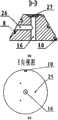
图6(a)刻有螺旋流管槽的锥形台主视图(b)D-D剖视图(c)E向视图;Fig. 6(a) front view of conical platform engraved with helical flow pipe groove (b) D-D sectional view (c) E-direction view;
图7(a)锥形罩主视图(b)F-F剖视图;Fig. 7 (a) front view of conical cover (b) F-F sectional view;
图8压电薄膜传感器的结构示意图;The structural schematic diagram of Fig. 8 piezoelectric film sensor;
图9(a)组合式锥形螺旋流管主视图(b)G-G剖视图;Figure 9 (a) front view of combined conical spiral flow tube (b) G-G sectional view;
图10陀螺测量角速度ωz(泵压差)原理示意图。Fig. 10 Schematic diagram of the principle of gyro measurement of angular velocity ωz (pump pressure difference).
具体实施方式Detailed ways
如图1、图2、图3、图4、图6所示,本实施例的基于锥形螺旋流管无阀压电泵的陀螺,包括由上盖13和下盖14密封组成的泵体,泵体内设有容纳有压电振子2的泵腔12,上盖13上固定设置有锥形台7,锥形台7底端固设在上盖13上,上盖13和下盖14通过螺栓11连接在一起;所述的锥形台7外表面设有围绕在其表面的锥形螺旋流管槽8,锥形台7外套设一锥形罩6,从而使锥形罩6覆盖在锥形螺旋流管槽8的开口上形成锥形螺旋流管;锥形罩6顶端开口并与锥形台7之间有一间隙,锥形台7中设有连通所述间隙和上盖13上通孔15的第一直流管16,所述的通孔15与泵腔12连通;锥形台7还设有与第一直流管16连通的第二直流管26,用于固定安装第二导管20,该导管作为泵的一个出入口;锥形螺旋流管槽8一端与间隙连通,另一端通过上盖5上的连通孔3与泵腔12连通;锥形台7顶端固定有一压电薄膜传感器17,所述的压电薄膜传感器17固定安装在间隙和第一直流管16之间,将第一直流管16与间隙隔开而不连通,从而形成压电泵的两个流道,而且通过锥形罩6上的小通孔18向外引出导线30;锥形罩6顶端开口处固定有与间隙连通的第一导管19,作为泵的另一个出入口。As shown in Fig. 1, Fig. 2, Fig. 3, Fig. 4 and Fig. 6, the gyroscope based on the conical spiral flow tube valveless piezoelectric pump of the present embodiment includes a pump body composed of an
如图6(c)所示,压电薄膜传感器17固定在第一直流管16顶端的阶梯状通孔27内;第二直流管26与第一直流管16相互垂直并连通,而且第二直流管26位于锥形螺旋流管槽8相邻的两段流槽之间。如图7所示,相应地,锥形罩6上与第二直流管26开口相对应的位置有一圆形开孔28,该圆形开孔28使得第二直流管26从锥形台7内部延伸至外部。As shown in Figure 6 (c), the
第一导管19与第二导管20开口端相互平行设置,且要根据需要进行弯折,开口端设置成与锥形台7的轴线平行或垂直。The open ends of the
如图3、图4、图6(a)所示,上盖13上设有定位螺孔22和圆形凹坑12,锥形台7的底面上设有与所述的定位螺孔22位置相对应的螺纹孔25,定位螺孔22与螺纹孔25相配合将锥形台7固定在圆形凹坑12内。As shown in Fig. 3, Fig. 4, Fig. 6 (a),
如图5所示,压电振子2粘结固定于下盖14上的阶梯状通孔24的阶梯处。As shown in FIG. 5 , the
如图6所示,所述的锥形螺旋流管槽8下端通过过渡槽10与连通孔3平缓连通。As shown in FIG. 6 , the lower end of the tapered spiral
如图7、图9所示,第一导管19通过锥形罩6上的圆形通孔9与间隙连通,锥形罩6上设有一微孔18,压电薄膜传感器21延伸出的导线30从该微孔18中穿出。As shown in Figures 7 and 9, the
如图8所示,压电薄膜力传感器是由压电薄膜31、双芯电缆30、小薄铜片33、导电胶34、绝缘和防湿薄膜29等构成的,压电薄膜31的两面各镀着一层导电膜,小薄铜片33粘贴在压电薄膜的表面,小薄铜片33的焊点32上焊了一种很细的弹性很好的双芯电缆30,在压电薄膜31、双芯电缆30、小薄铜片33、导电胶34涂有绝缘和防湿材料。当压电薄膜传感器两面的压力不同时,就会使压电薄膜31的两侧产生电荷,电荷信号经电荷放大器放大转成电信号后,经模数转换器到计算机接受分析、计算、并给出测试结果。在本发明中,使用压电薄膜力传感器,测量泵的输出压力。As shown in Figure 8, the piezoelectric film force sensor is made of
为了便于加工,锥形螺旋流管槽8的截面呈矩形。In order to facilitate processing, the cross section of the tapered spiral
为了防止使用过程中,陀螺各连接处产生流体渗漏,可以在各部件的连接处均匀涂硅胶密封。In order to prevent fluid leakage at the joints of the gyroscope during use, evenly apply silicone to the joints of the components for sealing.
本实施例中,上盖13、下盖14、锥形罩6均采用有机玻璃加工制造;刻有螺旋流管槽8的锥形台7可以采用铝加工制造,也可以采用有机玻璃加工制造;第一导管19、第二导管20采用市售件,可根据需求进行截取弯折;压电振子2采用市售件,直径为50mm,压电陶瓷片和金属片厚均为0.1mm,金属片的材料为黄铜;压电薄膜传感器17采用市售件,直径为10mm,厚度不超过0.1mm;螺栓(螺母)11、螺钉4为市售标准件,螺钉的规格为M2×5,螺栓的规格为M3×16,与螺栓配合的是规格为M3的六角螺母。In this embodiment, the
Claims (9)
Priority Applications (1)
| Application Number | Priority Date | Filing Date | Title |
|---|---|---|---|
| CN201110167553.2ACN102252666B (en) | 2011-06-21 | 2011-06-21 | A gyroscope based on a valveless piezoelectric pump with conical helical flow tube |
Applications Claiming Priority (1)
| Application Number | Priority Date | Filing Date | Title |
|---|---|---|---|
| CN201110167553.2ACN102252666B (en) | 2011-06-21 | 2011-06-21 | A gyroscope based on a valveless piezoelectric pump with conical helical flow tube |
Publications (2)
| Publication Number | Publication Date |
|---|---|
| CN102252666Atrue CN102252666A (en) | 2011-11-23 |
| CN102252666B CN102252666B (en) | 2014-04-23 |
Family
ID=44980083
Family Applications (1)
| Application Number | Title | Priority Date | Filing Date |
|---|---|---|---|
| CN201110167553.2AExpired - Fee RelatedCN102252666B (en) | 2011-06-21 | 2011-06-21 | A gyroscope based on a valveless piezoelectric pump with conical helical flow tube |
Country Status (1)
| Country | Link |
|---|---|
| CN (1) | CN102252666B (en) |
Cited By (1)
| Publication number | Priority date | Publication date | Assignee | Title |
|---|---|---|---|---|
| CN114353777A (en)* | 2022-01-10 | 2022-04-15 | 长春汽车工业高等专科学校 | A Piezo Synthetic Jet Gyro for Balancing Aircraft |
Citations (6)
| Publication number | Priority date | Publication date | Assignee | Title |
|---|---|---|---|---|
| US5267836A (en)* | 1992-09-28 | 1993-12-07 | Rockwell International Corporation | Madreporitic resonant pump |
| JP2001221166A (en)* | 2000-02-10 | 2001-08-17 | Furuyama Akimi | Displacement type pump with spiral pipes and fluid transfer method |
| US20060083639A1 (en)* | 2004-10-12 | 2006-04-20 | Industrial Technology Research Institute | PDMS valve-less micro pump structure and method for producing the same |
| EP1785652A1 (en)* | 2004-08-30 | 2007-05-16 | Star Micronics Co., Ltd. | Check valve and diaphragm pump |
| CN200955485Y (en)* | 2006-07-14 | 2007-10-03 | 北京工业大学 | Monolithic flow tube valveless piezoelectric pump |
| CN202119438U (en)* | 2011-06-21 | 2012-01-18 | 南京航空航天大学 | Gyro of valveless piezoelectric pump based on conic spiral flow pipe |
- 2011
- 2011-06-21CNCN201110167553.2Apatent/CN102252666B/ennot_activeExpired - Fee Related
Patent Citations (6)
| Publication number | Priority date | Publication date | Assignee | Title |
|---|---|---|---|---|
| US5267836A (en)* | 1992-09-28 | 1993-12-07 | Rockwell International Corporation | Madreporitic resonant pump |
| JP2001221166A (en)* | 2000-02-10 | 2001-08-17 | Furuyama Akimi | Displacement type pump with spiral pipes and fluid transfer method |
| EP1785652A1 (en)* | 2004-08-30 | 2007-05-16 | Star Micronics Co., Ltd. | Check valve and diaphragm pump |
| US20060083639A1 (en)* | 2004-10-12 | 2006-04-20 | Industrial Technology Research Institute | PDMS valve-less micro pump structure and method for producing the same |
| CN200955485Y (en)* | 2006-07-14 | 2007-10-03 | 北京工业大学 | Monolithic flow tube valveless piezoelectric pump |
| CN202119438U (en)* | 2011-06-21 | 2012-01-18 | 南京航空航天大学 | Gyro of valveless piezoelectric pump based on conic spiral flow pipe |
Non-Patent Citations (3)
| Title |
|---|
| 《中国优秀硕士学位论文全文数据库(工程科技Ⅱ辑)》 20110615 叶芳 "Y"形流管无阀压电泵的研究 1-9 , 第6期* |
| 叶芳: ""Y"形流管无阀压电泵的研究", 《中国优秀硕士学位论文全文数据库(工程科技Ⅱ辑)》, no. 6, 15 June 2011 (2011-06-15)* |
| 马薇等: "以PZT薄膜为驱动和传感的微型陀螺研制", 《压电与声光》, vol. 23, no. 1, 28 February 2001 (2001-02-28)* |
Cited By (1)
| Publication number | Priority date | Publication date | Assignee | Title |
|---|---|---|---|---|
| CN114353777A (en)* | 2022-01-10 | 2022-04-15 | 长春汽车工业高等专科学校 | A Piezo Synthetic Jet Gyro for Balancing Aircraft |
Also Published As
| Publication number | Publication date |
|---|---|
| CN102252666B (en) | 2014-04-23 |
Similar Documents
| Publication | Publication Date | Title |
|---|---|---|
| CN104235618B (en) | MEMS (Micro Electro Mechanical System) inertial measurement unit-based pipeline surveying and mapping and defect positioning device and pipeline surveying and mapping and defect positioning method thereof | |
| CN106969747B (en) | Static leveling system | |
| CN109282804B (en) | Single-axis fiber-optic gyroscope north-seeking algorithm | |
| CN109186638B (en) | Accelerometer servo circuit with controllable current scale factor and manufacturing process thereof | |
| CN107255475B (en) | A Symmetrical Structure Accelerometer North Finder and Dynamic Differential North Finding Method | |
| CN102331255B (en) | Gyro based on Fermat helical flow pipe valveless piezoelectric pump | |
| EP0158664A1 (en) | DEVICE FOR CORRECTING THE BAROMETER PRESSURE CAUSED BY ERRORS CAUSED BY THE WIND DIRECTION AND SPEED. | |
| CN107167626A (en) | Three-dimensional ultrasonic wind meter and wind detection method based on nonopiate survey wind formation | |
| CN103760616B (en) | Magnetic fluid compound gravity gradiometer | |
| CN202149775U (en) | Spinning top based on spiral flow tube valveless piezoelectric pump | |
| CN102252666B (en) | A gyroscope based on a valveless piezoelectric pump with conical helical flow tube | |
| Elaswad et al. | Basic and advanced inertial navigation fluid-based technology | |
| CN202119438U (en) | Gyro of valveless piezoelectric pump based on conic spiral flow pipe | |
| CN202119439U (en) | Gyro based on involute flow pipe electric pump free of valve pressure | |
| CN106917621B (en) | Small-aperture single-gyroscope horizontal well rotation directional inclination measurement device and method | |
| CN202599385U (en) | Continuous anchor cable on-way displacement measuring instrument | |
| CN205919910U (en) | From floating seabed temperature detect system | |
| CN202149777U (en) | Gyroscope based on Fermat spiral flow pipe valveless piezoelectric pump | |
| CN102338636B (en) | Gyroscope based on valveless piezoelectric pump of spiral flow pipe | |
| Tao et al. | Design of a MEMS sensor array for dam subsidence monitoring based on dualsensor cooperative measurements. | |
| CN202149776U (en) | Gyroscope based on Archimedean spiral flow pipe valveless piezoelectric pump | |
| CN102435184B (en) | Gyro based on lituus flow tube valveless piezoelectric pump | |
| CN114353777A (en) | A Piezo Synthetic Jet Gyro for Balancing Aircraft | |
| CN103245793A (en) | Method for measuring speed of ocean current through integrated navigation | |
| CN102338635B (en) | Gyro based on Archimedes spiral flow tube valveless piezoelectric pump |
Legal Events
| Date | Code | Title | Description |
|---|---|---|---|
| C06 | Publication | ||
| PB01 | Publication | ||
| C10 | Entry into substantive examination | ||
| SE01 | Entry into force of request for substantive examination | ||
| CB03 | Change of inventor or designer information | ||
| CB03 | Change of inventor or designer information | Inventor after:Zhang Jianhui Inventor after:Wang Jingshan Inventor after:Zhang Quan Inventor after:Tan Zhenzhen Inventor before:Zhang Jianhui Inventor before:Wang Jingshan | |
| COR | Change of bibliographic data | Free format text:CORRECT: INVENTOR; FROM: ZHANG JIANHUI WANG JINGSHAN TO: ZHANG JIANHUI WANG JINGSHAN ZHANG QUAN TAN ZHENZHEN | |
| C14 | Grant of patent or utility model | ||
| GR01 | Patent grant | ||
| CF01 | Termination of patent right due to non-payment of annual fee | ||
| CF01 | Termination of patent right due to non-payment of annual fee | Granted publication date:20140423 Termination date:20160621 |