CN102248947A - Object and vehicle detecting and tracking using a 3-D laser rangefinder - Google Patents
Object and vehicle detecting and tracking using a 3-D laser rangefinderDownload PDFInfo
- Publication number
- CN102248947A CN102248947ACN2011101209519ACN201110120951ACN102248947ACN 102248947 ACN102248947 ACN 102248947ACN 2011101209519 ACN2011101209519 ACN 2011101209519ACN 201110120951 ACN201110120951 ACN 201110120951ACN 102248947 ACN102248947 ACN 102248947A
- Authority
- CN
- China
- Prior art keywords
- target
- points
- vehicle
- dynamic
- ground
- Prior art date
- Legal status (The legal status is an assumption and is not a legal conclusion. Google has not performed a legal analysis and makes no representation as to the accuracy of the status listed.)
- Granted
Links
Images


Classifications
- G—PHYSICS
- G01—MEASURING; TESTING
- G01S—RADIO DIRECTION-FINDING; RADIO NAVIGATION; DETERMINING DISTANCE OR VELOCITY BY USE OF RADIO WAVES; LOCATING OR PRESENCE-DETECTING BY USE OF THE REFLECTION OR RERADIATION OF RADIO WAVES; ANALOGOUS ARRANGEMENTS USING OTHER WAVES
- G01S17/00—Systems using the reflection or reradiation of electromagnetic waves other than radio waves, e.g. lidar systems
- G01S17/02—Systems using the reflection of electromagnetic waves other than radio waves
- G01S17/06—Systems determining position data of a target
- G01S17/42—Simultaneous measurement of distance and other co-ordinates
- G—PHYSICS
- G01—MEASURING; TESTING
- G01S—RADIO DIRECTION-FINDING; RADIO NAVIGATION; DETERMINING DISTANCE OR VELOCITY BY USE OF RADIO WAVES; LOCATING OR PRESENCE-DETECTING BY USE OF THE REFLECTION OR RERADIATION OF RADIO WAVES; ANALOGOUS ARRANGEMENTS USING OTHER WAVES
- G01S17/00—Systems using the reflection or reradiation of electromagnetic waves other than radio waves, e.g. lidar systems
- G01S17/88—Lidar systems specially adapted for specific applications
- G01S17/89—Lidar systems specially adapted for specific applications for mapping or imaging
- G—PHYSICS
- G01—MEASURING; TESTING
- G01S—RADIO DIRECTION-FINDING; RADIO NAVIGATION; DETERMINING DISTANCE OR VELOCITY BY USE OF RADIO WAVES; LOCATING OR PRESENCE-DETECTING BY USE OF THE REFLECTION OR RERADIATION OF RADIO WAVES; ANALOGOUS ARRANGEMENTS USING OTHER WAVES
- G01S17/00—Systems using the reflection or reradiation of electromagnetic waves other than radio waves, e.g. lidar systems
- G01S17/88—Lidar systems specially adapted for specific applications
- G01S17/93—Lidar systems specially adapted for specific applications for anti-collision purposes
- G01S17/931—Lidar systems specially adapted for specific applications for anti-collision purposes of land vehicles
- G—PHYSICS
- G01—MEASURING; TESTING
- G01S—RADIO DIRECTION-FINDING; RADIO NAVIGATION; DETERMINING DISTANCE OR VELOCITY BY USE OF RADIO WAVES; LOCATING OR PRESENCE-DETECTING BY USE OF THE REFLECTION OR RERADIATION OF RADIO WAVES; ANALOGOUS ARRANGEMENTS USING OTHER WAVES
- G01S7/00—Details of systems according to groups G01S13/00, G01S15/00, G01S17/00
- G01S7/48—Details of systems according to groups G01S13/00, G01S15/00, G01S17/00 of systems according to group G01S17/00
- G01S7/4808—Evaluating distance, position or velocity data
- B—PERFORMING OPERATIONS; TRANSPORTING
- B60—VEHICLES IN GENERAL
- B60W—CONJOINT CONTROL OF VEHICLE SUB-UNITS OF DIFFERENT TYPE OR DIFFERENT FUNCTION; CONTROL SYSTEMS SPECIALLY ADAPTED FOR HYBRID VEHICLES; ROAD VEHICLE DRIVE CONTROL SYSTEMS FOR PURPOSES NOT RELATED TO THE CONTROL OF A PARTICULAR SUB-UNIT
- B60W30/00—Purposes of road vehicle drive control systems not related to the control of a particular sub-unit, e.g. of systems using conjoint control of vehicle sub-units
- B60W30/08—Active safety systems predicting or avoiding probable or impending collision or attempting to minimise its consequences
- B60W30/095—Predicting travel path or likelihood of collision
- B60W30/0956—Predicting travel path or likelihood of collision the prediction being responsive to traffic or environmental parameters
- G—PHYSICS
- G08—SIGNALLING
- G08G—TRAFFIC CONTROL SYSTEMS
- G08G1/00—Traffic control systems for road vehicles
- G08G1/16—Anti-collision systems
- G08G1/165—Anti-collision systems for passive traffic, e.g. including static obstacles, trees
- G—PHYSICS
- G08—SIGNALLING
- G08G—TRAFFIC CONTROL SYSTEMS
- G08G1/00—Traffic control systems for road vehicles
- G08G1/16—Anti-collision systems
- G08G1/166—Anti-collision systems for active traffic, e.g. moving vehicles, pedestrians, bikes
Landscapes
- Physics & Mathematics (AREA)
- Engineering & Computer Science (AREA)
- Computer Networks & Wireless Communication (AREA)
- Electromagnetism (AREA)
- General Physics & Mathematics (AREA)
- Radar, Positioning & Navigation (AREA)
- Remote Sensing (AREA)
- Traffic Control Systems (AREA)
- Optical Radar Systems And Details Thereof (AREA)
Abstract
Translated fromChinese
Description
Translated fromChinese技术领域technical field
本发明总体上涉及目标检测方法和系统,且更具体地涉及使用三维激光测距仪来检测和跟踪车辆附近的静止和移动目标两者的目标检测方法和系统,从而给下游车辆控制应用提供输入源。The present invention relates generally to object detection methods and systems, and more particularly to object detection methods and systems that use three-dimensional laser range finders to detect and track both stationary and moving objects in the vicinity of a vehicle to provide input to downstream vehicle control applications source.
背景技术Background technique
许多现代车辆包括用于安全和导航辅助的各种复杂电子系统。在一些车辆中,这些系统包括目标检测和适应性巡航控制系统,其可以警告驾驶员车辆附近的障碍物,或甚至控制车辆制动器或转向装置以保持距另一个车辆或目标的安全距离。然而,本领域已知且在市场上可用的目标检测系统在它们可以多好地检测和跟踪目标以及目标数据可以多可靠地用于车辆控制目的方面具有限制。Many modern vehicles include various complex electronic systems for safety and navigation aids. In some vehicles, these systems include object detection and adaptive cruise control systems, which can warn the driver of obstacles near the vehicle, or even control the vehicle's brakes or steering to maintain a safe distance from another vehicle or object. However, object detection systems known in the art and available on the market have limitations in how well they can detect and track objects and how reliably object data can be used for vehicle control purposes.
当今车辆中可用的大多数目标检测系统使用基于雷达或照相机的视觉技术。这些系统通常具有在实际驾驶情况中通常发现的杂乱环境中的目标之间进行区分的问题。它们可能能够检测目标的二维形状,但是不能确定目标高度,从而不能确定目标实际上是否为地面或道路表面特征。或者它们可能能够检测目标的存在,但是不能基于相对速度或三维特性在紧密隔开的目标之间进行区分。最后,由于缺乏反射或缺乏目标的颜色差异,现有基于雷达或照相机的目标检测系统可能完全不能检测一些目标。Most object detection systems available in vehicles today use radar- or camera-based vision technology. These systems often have the problem of distinguishing between objects in the cluttered environment typically found in real driving situations. They may be able to detect the two-dimensional shape of an object, but cannot determine object height and thus whether the object is actually a ground or road surface feature. Or they may be able to detect the presence of objects, but not distinguish between closely spaced objects based on relative velocity or three-dimensional properties. Finally, existing radar- or camera-based object detection systems may fail to detect some objects at all due to lack of reflection or lack of color differences of the objects.
需要一种可靠和稳固的目标检测系统,其可以将目标彼此或者与地平面进行区分,其可以可靠地跟踪所检测目标相对于地面以及相对于主车辆的位置和速度两者,其可以在实际世界驾驶的杂乱环境中执行这些任务。这种系统可以允许在开发先进车辆系统(例如,半自主驾驶系统)中的显著突破。There is a need for a reliable and robust object detection system that can distinguish objects from each other or from the ground plane, that can reliably track the position and velocity of detected objects both relative to the ground and relative to the host vehicle, and that can be used in real time Perform these tasks in the cluttered environment of the world of driving. Such a system could allow a significant breakthrough in the development of advanced vehicle systems (eg, semi-autonomous driving systems).
发明内容Contents of the invention
根据本发明的教导,公开了一种使用三维激光测距仪来检测和跟踪车辆附近的目标的方法和系统。所述方法从激光测距仪接收点云,其中,所述点表示测距仪感测一些目标存在的空间位置。算法首先基于先前地平面位置、来自于底盘动态传感器的数据、以及应用于点云数据的特征矢量计算来估计地平面位置。也可以构造不平坦的分段地表面。接下来,基于点云数据结合地表面计算静止目标的平面图占位映射和标高映射。最后,检测和跟踪动态目标,感测相对于地面移动的目标,例如其它车辆、行人和动物。方法的输出是静止和动态目标集合,包括其大小和形状、距离以及相对于地面和主车辆的速度。该输出数据可以由下游应用使用,例如碰撞避免或半自主驾驶系统。In accordance with the teachings of the present invention, a method and system for detecting and tracking objects near a vehicle using a three-dimensional laser range finder is disclosed. The method receives a point cloud from a laser range finder, wherein the points represent spatial locations where the range finder senses the presence of some objects. The algorithm first estimates the ground level position based on the previous ground level position, data from the chassis dynamics sensors, and eigenvector calculations applied to the point cloud data. Uneven segmented ground surfaces can also be constructed. Next, the floor plan occupancy mapping and elevation mapping of the stationary target are calculated based on the point cloud data and the ground surface. Finally, detect and track dynamic objects, sensing objects that move relative to the ground, such as other vehicles, pedestrians, and animals. The output of the method is a collection of stationary and dynamic objects, including their size and shape, distance, and velocity relative to the ground and the host vehicle. This output data can be used by downstream applications, such as collision avoidance or semi-autonomous driving systems.
方案1. 一种用于检测和跟踪车辆附近的目标的方法,所述方法包括:
从激光测距仪提供多个扫描点,所述扫描点表示车辆周围空间中的激光测距仪已经检测到目标的位置;providing a plurality of scan points from the laser rangefinder, the scan points representing locations in the space surrounding the vehicle where the laser rangefinder has detected the target;
使用扫描点和车辆动态数据来建立地平面的位置;Use scan points and vehicle dynamics data to establish the location of the ground plane;
使用扫描点和地平面的位置来构造目标占位映射和目标标高映射;以及using the locations of the scan points and the ground plane to construct the target occupancy map and target elevation map; and
使用扫描点和目标占位映射来生成动态目标数据,其中,所述动态目标数据识别和跟踪移动的目标。The scan points and target occupancy maps are used to generate dynamic target data that identifies and tracks moving targets.
方案2. 根据方案1所述的方法,其中,使用扫描点和车辆动态数据来建立地平面的位置包括:
使用车辆俯仰角和倾侧角数据来从先前地平面位置计算预测地平面位置;using the vehicle pitch and roll data to calculate a predicted ground level position from a previous ground level position;
在扫描点上执行选通操作,其中,选通操作使用预测地平面位置来识别要在地平面计算中包括的点集合;performing a gating operation on the scanned points, wherein the gating operation uses the predicted ground level location to identify a set of points to include in the ground level calculation;
生成矩阵,所述矩阵包含要在地平面计算中包括的点集合;generating a matrix containing the set of points to be included in the ground plane calculation;
在矩阵上执行特征值分解,以识别最小特征值以及与最小特征值相关的特征矢量;以及performing an eigenvalue decomposition on the matrix to identify the smallest eigenvalue and the eigenvector associated with the smallest eigenvalue; and
使用与最小特征值相关的特征矢量来确定地平面的方程。Use the eigenvector associated with the smallest eigenvalue to determine the equation for the ground plane.
方案3. 根据方案2所述的方法,还包括使用卡尔曼滤波器提供更新地平面位置。Option 3. The method according to
方案4. 根据方案1所述的方法,其中,使用扫描点和地平面的位置来构造目标占位映射和目标标高映射包括:Scheme 4. The method according to
将每个扫描点投影到地平面以确定每个扫描点的地平面相交点和法向矢量;Project each scan point onto the ground plane to determine the ground plane intersection and normal vector for each scan point;
使用所有扫描点的法向矢量来构建目标标高映射,其中,所述目标标高映射示出了在车辆周围空间中检测的所有目标的高度信息;以及using the normal vectors of all scan points to construct an object elevation map showing height information for all objects detected in the space around the vehicle; and
使用所有扫描点的地平面相交点来构建目标占位映射,其中,所述目标占位映射示出了在车辆周围空间中检测的所有目标的位置信息。The ground plane intersection of all scan points is used to construct an object occupancy map showing position information of all objects detected in the space around the vehicle.
方案5. 根据方案1所述的方法,其中,使用扫描点和目标占位映射来生成动态目标数据包括:Scheme 5. The method according to
从扫描点去除地面点以生成目标点集合;remove ground points from scan points to generate a set of target points;
使用最近计算的目标占位映射;Use the most recently computed target occupancy map;
构造相似性曲线以确定哪些目标点一起移动;construct similarity curves to determine which target points move together;
将一起移动的目标点组聚类成动态目标;Clustering groups of target points that move together into dynamic targets;
将动态目标分类成目标类型,其中,目标类型包括车辆、行人、自行车和动物;Classify dynamic targets into target types, where target types include vehicles, pedestrians, bicycles and animals;
计算动态目标的质心;以及Compute the centroid of the dynamic object; and
跟踪动态目标以生成动态目标数据。Track dynamic goals to generate dynamic goal data.
方案6. 根据方案5所述的方法,其中,将一起移动的目标点组聚类成动态目标使用深度优先搜索策略。Scheme 6. The method according to scheme 5, wherein clustering target point groups moving together into dynamic targets uses a depth-first search strategy.
方案7. 根据方案5所述的方法,其中,跟踪动态目标使用卡尔曼滤波器。Scheme 7. The method according to scheme 5, wherein the tracking dynamic target uses a Kalman filter.
方案8. 根据方案5所述的方法,其中,动态目标数据包括每个动态目标相对于地面的纵向和横向位置以及纵向和横向速度。Item 8. The method according to item 5, wherein the dynamic target data includes longitudinal and lateral positions and longitudinal and lateral velocities of each dynamic target relative to the ground.
方案9. 根据方案1所述的方法,还包括在车辆应用中使用目标占位映射和动态目标数据。Embodiment 9. The method of
方案10. 一种用于检测和跟踪车辆附近的目标的方法,所述方法包括:
从激光测距仪提供多个扫描点,所述扫描点表示车辆周围空间中的激光测距仪已经检测到目标的位置;providing a plurality of scan points from the laser rangefinder, the scan points representing locations in the space surrounding the vehicle where the laser rangefinder has detected the target;
使用扫描点和车辆动态数据来建立地表面的定义;Use scan points and vehicle dynamics data to establish the definition of the ground surface;
使用扫描点和地表面的定义来构造目标占位映射和目标标高映射;Use scan points and ground surface definitions to construct target occupancy maps and target elevation maps;
使用扫描点和目标占位映射来生成动态目标数据,其中,所述动态目标数据识别和跟踪移动的目标;以及using the scan points and target occupancy maps to generate dynamic target data, wherein the dynamic target data identifies and tracks moving targets; and
在车辆应用中使用目标占位映射和动态目标数据。Use object occupancy mapping and dynamic object data in vehicle applications.
方案11. 根据方案10所述的方法,其中,使用扫描点和车辆动态数据来建立地表面的定义包括使用维诺图方法来构造不平坦地表面分段。Embodiment 11. The method of
方案12. 根据方案10所述的方法,其中,使用扫描点和地表面的定义来构造目标占位映射和目标标高映射包括:
将每个扫描点投影到地表面以确定每个扫描点的地表面相交点和法向矢量;Project each scan point onto the ground surface to determine the ground surface intersection and normal vector for each scan point;
使用所有扫描点的法向矢量来构建目标标高映射,其中,所述目标标高映射示出了在车辆周围空间中检测的所有目标的高度信息;以及using the normal vectors of all scan points to construct an object elevation map showing height information for all objects detected in the space around the vehicle; and
使用所有扫描点的地表面相交点来构建目标占位映射,其中,所述目标占位映射示出了在车辆周围空间中检测的所有目标的位置信息。The ground surface intersection points of all scan points are used to construct an object occupancy map showing position information of all objects detected in the space around the vehicle.
方案13. 根据方案10所述的方法,其中,使用扫描点和目标占位映射来生成动态目标数据包括:Scheme 13. The method according to
从扫描点去除地面点以生成目标点集合;remove ground points from scan points to generate a set of target points;
使用最近计算的目标占位映射;Use the most recently computed target occupancy map;
构造相似性曲线以确定哪些目标点一起移动;construct similarity curves to determine which target points move together;
将一起移动的目标点组聚类成动态目标;Clustering groups of target points that move together into dynamic targets;
将动态目标分类成目标类型,其中,目标类型包括车辆、行人、自行车和动物;Classify dynamic targets into target types, where target types include vehicles, pedestrians, bicycles and animals;
计算动态目标的质心;以及Compute the centroid of the dynamic object; and
跟踪动态目标以生成动态目标数据。Track dynamic goals to generate dynamic goal data.
方案14. 根据方案13所述的方法,其中,将一起移动的目标点组聚类成动态目标包括构造相似性曲线、使用深度优先搜索策略以及使用具有散列表的网格数据结构。
方案15. 一种用于检测和跟踪车辆附近的目标的系统,所述系统包括:Embodiment 15. A system for detecting and tracking objects near a vehicle, the system comprising:
车辆中的激光测距仪,用于提供多个扫描点,所述扫描点表示车辆周围空间中的激光测距仪已经检测到目标的位置;a laser rangefinder in the vehicle for providing a plurality of scan points representing locations in the space surrounding the vehicle where the laser rangefinder has detected the target;
第一处理器,所述第一处理器配置成使用扫描点来计算地表面且生成目标占位映射;a first processor configured to use the scan points to calculate a ground surface and generate a target occupancy map;
第二处理器,所述第二处理器配置成使用目标占位映射和扫描点来识别和跟踪动态目标;以及a second processor configured to identify and track a dynamic target using the target occupancy map and scan points; and
共享存储器模块,用于在第一处理器和第二处理器之间共享数据。A shared memory module for sharing data between the first processor and the second processor.
方案16. 根据方案15所述的系统,其中,第一处理器包括地表面跟踪模块,所述地表面跟踪模块包括:选通算法,用于识别要在地平面计算矩阵中包括的点集合;以及特征值分解算法,用于从地平面计算矩阵计算地平面的方程。
方案17. 根据方案16所述的系统,其中,第一处理器中的地表面跟踪模块还包括地表面分段算法,其使用维诺图方法来构造不平坦地表面分段。Item 17. The system of
方案18. 根据方案15所述的系统,其中,第一处理器包括目标占位模块,所述目标占位模块包括:地表面投影算法,用于将所有扫描点正交地投影到地表面;标高映射构造算法,用于构造标高映射,标高映射示出了在车辆周围空间中检测的所有目标的高度信息;以及占位映射构造算法,用于构造占位映射,占位映射示出了在车辆周围空间中检测的所有目标的位置信息。
方案19. 根据方案15所述的系统,其中,第二处理器包括目标聚类模块,用于将一起移动的目标点聚类成动态目标;目标分类模块,用于将动态目标分类成目标类型;以及目标跟踪模块,用于提供关于每个动态目标的位置和速度信息。Scheme 19. The system according to scheme 15, wherein the second processor includes a target clustering module for clustering target points moving together into dynamic targets; a target classification module for classifying the dynamic targets into target types ; and a target tracking module for providing position and velocity information about each dynamic target.
方案20. 根据方案15所述的系统,还包括车辆中的第二激光测距仪。
本发明的附加特征从以下说明和所附权利要求结合附图显而易见。Additional features of the present invention will become apparent from the following description and appended claims when taken in conjunction with the accompanying drawings.
附图说明Description of drawings
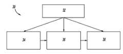
图1是根据本发明实施例的可以用于目标检测和跟踪的硬件系统的框图;Fig. 1 is a block diagram of a hardware system that can be used for target detection and tracking according to an embodiment of the present invention;
图2是使用图1的硬件系统的元件来检测和跟踪目标的软件系统的框图;2 is a block diagram of a software system for detecting and tracking targets using elements of the hardware system of FIG. 1;
图3是由图2的软件系统的地平面跟踪模块使用的过程的流程图;3 is a flowchart of a process used by the ground level tracking module of the software system of FIG. 2;
图4是用于计算分段地表面的投影到地平面(可能不是平坦的)的点集合的维诺图;Figure 4 is a Voronoi diagram of the set of points used to calculate the projection of the segmented ground surface onto the ground plane (which may not be flat);
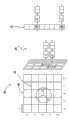
图5是示出了扫描点如何以网格设置以改进分段地表面计算的效率的简图;Figure 5 is a diagram showing how scan points are arranged in a grid to improve the efficiency of segmented ground surface calculations;
图6是由图2的软件系统的静止占位映射模块使用的过程的流程图;FIG. 6 is a flowchart of a process used by the static occupancy mapping module of the software system of FIG. 2;
图7是由图2的软件系统的静止占位映射模块产生的二元占位映射的示例;7 is an example of a binary occupancy map generated by a static occupancy mapping module of the software system of FIG. 2;
图8是由图2的软件系统的动态目标跟踪模块使用的过程的流程图;和8 is a flowchart of a process used by the dynamic object tracking module of the software system of FIG. 2; and
图9是示出了在图2的软件系统的动态目标跟踪模块中扫描点如何聚类成目标的简图。FIG. 9 is a diagram illustrating how scan points are clustered into objects in the dynamic object tracking module of the software system of FIG. 2 .
具体实施方式Detailed ways
涉及使用三维激光测距仪的目标检测和跟踪的方法和系统的本发明实施例的以下阐述本质上仅仅是示例性的且绝不旨在限制本发明或其应用或使用。The following description of embodiments of the invention relating to methods and systems for object detection and tracking using a three-dimensional laser range finder is merely exemplary in nature and is in no way intended to limit the invention or its application or use.
车辆碰撞避免和半自主驾驶系统需要关于其周围环境中的目标的非常精确的信息以便有效。使用基于雷达或照相机的视觉技术的常规目标检测系统可能具有辨别杂乱环境中的目标的问题,这在实际世界驾驶情况下是典型的。例如,基于雷达的系统可能不会可靠地检测非金属目标,例如分立路边、石头和植物。基于照相机的视觉系统可能难以在类似颜色或亮度的目标之间进行辨别,且不能直接地测量距目标的测距或范围。在本发明中,三维(3-D)激光测距仪用于获取点云,表示主车辆附近的目标,特定算法用于计算车辆周围空间中的地平面以及静止和动态目标的映射。Vehicle collision avoidance and semi-autonomous driving systems require very precise information about objects in their surroundings in order to be effective. Conventional object detection systems using radar- or camera-based vision techniques can have problems discerning objects in cluttered environments, which is typical in real-world driving situations. For example, radar-based systems may not reliably detect non-metallic targets such as discrete road curbs, stones, and vegetation. Camera-based vision systems may have difficulty distinguishing between objects of similar color or brightness, and cannot directly measure range or range from an object. In the present invention, a three-dimensional (3-D) laser rangefinder is used to acquire a point cloud representing objects near the host vehicle, and specific algorithms are used to calculate the ground plane and the mapping of stationary and dynamic objects in the space around the vehicle.
图1是可以用于根据本发明的目标检测和跟踪的硬件系统10的框图。车辆12包含能够三维地快速扫描车辆12周围环境的3-D激光测距仪14。如果适当,可以使用多于一个的激光测距仪14,以更完全和快速地扫描整个360度视界。激光测距仪14使用有时称为光检测和测距(LIDAR)的技术,且提供表示激光碰到的目标的点云数据。所述点可以由激光测距仪14按照方位和仰角加上测距来表示,其可以容易地转换为相对于附连到车辆12的本地坐标框架的(x, y, z)点数据。激光测距仪14将点云数据提供给可现场编程的门阵列(FPGA)16,其是设计成由顾客配置(在该情况下是车辆制造商,在制造之后)的集成电路。FIG. 1 is a block diagram of a
FPGA 16从测距仪14接收点云数据且执行涉及地平面和目标检测的一系列计算。FPGA 16的能够可以由任何合适处理器处理,包括通用电子控制单元或者专用集成电路(ASIC)。专用集成电路是针对特定用途定制的集成电路,而不旨在用于通用用途。由于ASIC的高开发成本以及全功能电子控制单元的高成本,在硬件系统10的优选实施例中设想FPGA 16。
FPGA 16将其输出发送到另一个处理器,在该情况下是数字信号处理器(DAP)18。DSP 18基于点云数据和先前计算的目标数据来执行下述的附加计算,从而得到车辆12附近的地平面、静止目标和动态目标的完整表示。FPGA 16和DSP 18两者均接入共享存储器模块20。
图2是使用硬件系统10的元件检测和跟踪目标的软件系统30的框图。总图像处理模块32管理整个软件系统30的功能。地平面跟踪模块34使用点云数据和其它信息以估计地表面的当前位置,如下文详细所述。接下来,静止占位映射模块36使用点云数据和先前计算的地表面作为输入来计算所有检测目标的位置和高度。下文还将提供静止占位映射模块36中的计算细节。最后,动态目标跟踪模块38使用下文详细描述的方法来计算移动目标的形状、位置和速度。FIG. 2 is a block diagram of a
图3是由软件系统30的地平面跟踪模块34使用的过程的流程图40。过程在框42开始,由总图像处理模块32指导,例如在车辆发动机启动时。过程在决策菱形块44等待来自于先前地平面估计的新数据变得可用。在框46,来自于先前计算步骤的估计地平面用作新地平面计算的基础或起始点。在车辆12启动之后过程的第一关,在没有紧接先前地平面数据可用时,在框46可以使用来自于车辆12先前操作的最后一个地平面或者在框46可以使用基于车辆标称行驶高度的缺省值。在框48,作出关于地平面相对于来自于框46的先前地平面的预期移动的预测。框48处的预测基于许多现代车辆中可用类型的车载惯性测量单元(IMU)。来自于框48处的预测中使用的IMU的数据包括车辆俯仰角和侧倾角,如果这些角度从先前地平面计算以来已经发生变化,其将对地平面的位置和取向具有显著影响。FIG. 3 is a flowchart 40 of a process used by the ground
在框50,提供来自于激光测距仪14的最近点云数据。这包括所有点数据,包括表示远高于地面水平的高目标的点。在框52,在点云数据上进行选通或滤波,以仅仅选择被估计表示地平面的点。框52处的选通操作通过计算每个点距预测地平面的距离来进行。限定阈值高度,例如0.25米,且距地平面距离小于阈值的任何点被认为是地面点。所有其它点(即,距地平面距离大于阈值距离的点)被认为是目标点,且在地平面计算中不使用。At
在框54,表示地平面的点集合用于进一步分析。要注意的是,在框54处提供的点不都处于一个平面内。相反,从框52处的选通操作输出的点(其在框54使用)是被认为由地面或道路表面返回的点,且这些点用于确定最佳地拟合所述点的平面的计算。在框56,来自于框54的地面点放置在4×N矩阵中,且在矩阵上进行特征值分解,目标是寻找由以下方程表示的地平面:At block 54, the set of points representing the ground plane is used for further analysis. Note that the points provided at box 54 do not all lie in one plane. Instead, the points output from the gating operation at box 52 (which are used at box 54) are points considered to be returned by the ground or road surface, and these points are used in the calculation to determine the plane that best fits the points . At
Ax+By+Cz+D=0 (1)Ax+By+Cz+D=0 (1)
框56的动作如下进行。来自于框54的N个地面点中的每个的(x, y, z)坐标用于填充4×N矩阵的前三列,第四列为数字1。即,矩阵的第一行将包括第一个地面点的坐标加上数字1,如下:[x1, y1, z1, 1]。矩阵的第二行将包括第二个地面点的坐标加上数字1,如下:[x2, y2, z2, 1]。由此,4×N矩阵用来自于框54的所有地面点填充。然后,可以在矩阵上进行特征值分解,从而产生一组特征值和特征矢量,如下文所述。最小特征值可以认为具有来自于最佳地拟合矩阵中包含的点数据的平面方程的系数[A, B, C, D]。在框58,使用方程(1)和在框56刚刚确定的系数[A, B, C, D]限定更新地平面,且过程循环回到决策菱形块44。The action of
以下是在流程图40所示过程中使用的计算的详细讨论。在框48,假定主车辆的俯仰角速度和侧倾角速度的IMU测量值分别为 


nTp+d=0 (2)nT p + d = 0 (2)
其中,n表示地平面的单位法线矢量(即,||n||=1),|d|表示从3D传感器到地平面的距离,p表示平面上的点。where n denotes the unit normal vector of the ground plane (ie, ||n||=1), |d| denotes the distance from the 3D sensor to the ground plane, and p denotes a point on the plane.
地平面的法线n可以表示为相对于主车辆坐标系的俯仰角(


只要新数据到达,算法就开始。假定先前时间瞬时的地平面为x,当前时间瞬时的状态矢量表示为x′。那么系统动态方程可以写为:The algorithm starts whenever new data arrives. Assume that the ground plane at the previous time instant is x, and the state vector at the current time instant is denoted as x'. Then the system dynamic equation can be written as:

或者简短地写为:or shortly written as:

其中,ΔT是取样时间间隔,

预测地平面x′可以转换为笛卡尔方程形式:,其中,

假定是从点p到地平面的距离。在流程图40中框52处的选通操作通过以下标准从来自于3D传感器的收集3D点云选择地面点:如果D≤TH,那么点p是地面点且被选择;否则p是目标或障碍物点。在此,TH是高度阈值,例如0.25米。assumed is the distance from point p to the ground plane. The gating operation at
假定地面点集合表示为:

其中,
方程(4)的解是矩阵D的最小特征值的特征矢量,即:The solution to equation (4) is the eigenvector of the smallest eigenvalue of matrix D, namely:

其中,λm是最小特征值。Among them, λm is the minimum eigenvalue.
假定


因而,卡尔曼滤波器测量方程可以写成俯仰角(


或者简短地写为:or shortly written as:

其中

基于方程(4)和(9)的扩展卡尔曼滤波器过程在流程图40中的框58处应用于更新地平面操作。The extended Kalman filter process based on equations (4) and (9) is applied at
要注意的是,地平面跟踪模块34以及流程图40的过程的输出是数学意义上的真实平面。即,地平面不由3-D空间中的可能模糊点群表示,而相反由方程(2)的确定数学公式表示。Note that the output of the ground
上述地平面仅仅是道路表面的近似。存在道路表面不平坦的许多情况:例如,排水梯度、趋近斜坡道路、诸如坑和石头的小不连续物、以及具有超高的道路。为了考虑此,还可以将道路表示为分块或分段表面,而不是平面表面。The ground plane above is only an approximation of the road surface. There are many cases where road surfaces are uneven: for example, drainage gradients, roads approaching slopes, small discontinuities such as pots and stones, and roads with superelevation. To account for this, roads can also be represented as tiled or segmented surfaces rather than planar surfaces.
假定平面地面近似为方程nTp+d=0(即,上述地平面跟踪模块的结果),那么3D点p可以表示为从地平面投影点p′到标高e的映射或者由样本集合
图4示出了地平面上的投影点{p′}的维诺图200。在图200中,点p′的邻域可以定义为维诺单元与单元p′共用共同边缘的点;例如,单元204-216中的点a、b、c、d、e、f、g是维诺图意义上的单元202中的点p′的邻域。因而,可以构造曲线G1=(V, E),其中,矢量集合是投影点集合{p′};边缘集合E仅仅包括在维诺图200中将每个点连接到其直接邻域的边缘。FIG. 4 shows a Voronoi diagram 200 of a projected point {p'} on the ground plane. In graph 200, the neighborhood of point p' can be defined as the points where Voronoi cells share a common edge with cell p'; for example, points a, b, c, d, e, f, g in cells 204-216 are The neighborhood of point p' in cell 202 in the sense of a Voronoi diagram. Thus, the curve G1 =(V, E) can be constructed, where the set of vectors is the set of projected points {p'}; the set of edges E includes only the edges connecting each point to its immediate neighbors in the Voronoi diagram 200 .
每个边缘


其中ei和ej分别是顶点vi和vj的标高。where ei and ej are the elevations of vertices vi and vj respectively.
接下来,基于曲线的有效方法用于将3D点云分段成一组平滑表面。分段是将V分成不重叠子集,使得每个子集V′形成子曲线
定义谓项(二元函数)P,用于评估在两个部分Γ1和Γ2之间是否存在边界:Define a predicate (binary function) P that evaluates whether a boundary exists between two parts Γ1 and Γ2 :

其中,函数表示两个部分


部分Γ的内部差度量定义为在部分最小生成树中的边缘中的最大权重。


试探函数τ调整至这样的程度,相互差必须大于其内部偏差以便确定是否存在边界条件。试探函数τ的两个示例列举如下。The trial function τ is adjusted to such an extent that the mutual difference must be greater than its internal deviation in order to determine whether a boundary condition exists. Two examples of the trial function τ are listed below.
第一,阈值函数基于部分的大小:First, the threshold function is based on the size of the section:

其中,|Γ|是集合Γ的大小。方程(14)意味着对于小的部分大小,我们需要边界的较强显著性。参数ks的大值引起对大尺寸部分的偏好。where |Γ| is the size of the set Γ. Equation (14) implies that for small portion sizes we need stronger saliency of the boundaries. Large values of the parameter ks induce a preference for large sized portions.
第二,阈值函数基于距主车辆所定位的原点的距离:Second, the threshold function is based on the distance from the origin where the host vehicle is located:

其中,r|Γ|表示部分Γ的平均位置,kr是预先选定参数。where r|Γ| represents the average position of part Γ and kr is a pre-selected parameter.
方程(15)意味着附近部分需要比遥远的部分更强的边界显著性。这是因为扫描点在附近区域比远距离区域(较少信息)中更密(更多信息)。参数kr的较小值引起对附近区域中大尺寸部分的偏好。Equation (15) implies that nearby parts require stronger boundary saliency than distant parts. This is because the scan points are denser (more informative) in nearby regions than in distant regions (less informative). Smaller values of the parameter kr cause a preference for large-sized fractions in nearby areas.
现在可以定义基于曲线的分段算法。输入是具有N个顶点和M个边缘的曲线G1=(V, E)。输出是V分段成部分
1) 通过非减边缘权重将E分类为(e1, e2, …, eM)1) Classify E as (e1 , e2 , …, eM ) by non-subtractive edge weights
2) 用部段C0开始,其中,每个顶点处于其自己的部分中2) Start with section C0 where each vertex is in its own section
3) 基于Cn-1构造分区Cn,如下:3) Construct partition Cn based on Cn-1 , as follows:
a) 直接将Cn-1复制到Cna) Copy Cn-1 directly to Cn
b) 假定(vi, vj)为边缘en,排序边缘列表中的第n个边缘;如果vi和vj处于独立部分Γi和Γj中,且谓项P(Γ1,Γ2)为假,那么将两个部分Γi和Γj合并成Cn的Γi,且从Cn去除Γjb) Suppose (vi , vj ) is an edge en , sort the nth edge in the edge list; if vi and vj are in independent parts Γi and Γj , and the predicate P(Γ1 ,Γ2 ) is false, then the two parts Γi and Γj are merged into Γi of Cn , and Γj is removed from Cn
c) 对于n=1, … ,M,重复步骤3)c) For n=1, … ,M, repeat step 3)
4) 将集合CM输出为C4) Output the set CM as C
一旦获得来自于上述算法的分段结果,就可以识别地表面点集合Γgound,其为包围主车辆位置(即车辆坐标框架的原点)的C中的最大部分。Once the segmented results from the above algorithm are obtained, the set of ground surface points Γgoound can be identified, which is the largest part of C that encloses the host vehicle position (ie the origin of the vehicle's coordinate frame).
上述内容阐述在仅知道3D点云时的一般方法。直接应用该方法可能是计算量大的。在以下说明中,假定除了3D位置之外,对于每个扫描点,已知扫描光栅网格的位置,即相应象素的行和列。在此,算法可以重新设计以利用该光栅网格信息,以便改进计算效率。The foregoing illustrates a general approach when only the 3D point cloud is known. Applying this method directly can be computationally expensive. In the following description it is assumed that in addition to the 3D position, for each scanning point, the position of the scanned raster grid, ie the row and column of the corresponding pixel, is known. Here, algorithms can be redesigned to take advantage of this raster mesh information in order to improve computational efficiency.
图5是示出了测距仪扫描点如何以二维网格设置的简图240。由于大多数3D测距仪传感器(例如激光测距仪14)的物理设计,扫描点可以如简图240所示组织。每个象素表示具体球面角且包含对最接近障碍物表面的距离测量。传感器沿水平扫描线242和竖直扫描线244扫描,且自然地产生网格曲线G2=(V, E),其中,V是投影点集合,边缘E仅包括从象素到其邻域明显的边缘。简图240示出了在内部3×3网格中边缘从象素246到其8个邻域(N、NE、E、SE、S、SW、W、NW)明显的示例。FIG. 5 is a diagram 240 showing how rangefinder scan points are arranged in a two-dimensional grid. Due to the physical design of most 3D rangefinder sensors (eg, laser rangefinder 14 ), scan points may be organized as shown in
每个边缘

其中,(p’i, ei)和(p’j, ej)分别表示顶点vi和vj的投影和标高,Tsep是距离阈值(例如,1.2 m)。要注意的是,具有无穷大权重的边缘可以从E去除。where (p'i , ei ) and (p'j , ej ) denote the projection and elevation of vertices vi and vj , respectively, and Tsep is the distance threshold (eg, 1.2 m). Note that edges with infinite weights can be removed from E.
要注意的是,修正分段算法将水平和竖直边缘处理解耦。上述四步骤分段算法首先独立地应用于每个水平扫描线,仅考虑水平边缘(即,简图240中的边缘E和W)。然后,水平扫描线中的分段片段使用竖直边缘(即,简图240中的NW、N、NE、SW、S和SE)基于限定谓项值合并。Note that the modified segmentation algorithm decouples horizontal and vertical edge processing. The four-step segmentation algorithm described above is first applied to each horizontal scan line independently, considering only horizontal edges (ie, edges E and W in diagram 240 ). The segmented segments in the horizontal scan line are then merged using vertical edges (ie, NW, N, NE, SW, S, and SE in diagram 240 ) based on the defined predicate values.
修正分段算法的输入是具有N个顶点的网格曲线G2=(V, E)。边缘集合

1)对于每个水平扫描线r:1) For each horizontal scanline r:
a)构建子曲线Gr=(Vr, Er),其中,顶点Vr是第r个扫描线;
b)将上述四步骤分段算法应用于行曲线Grb) Apply the above four-step segmental algorithm to the row curve Gr
2)通过非减边缘权重将所有竖直边缘EV分类为(e1, e2, …, )2) Classify all vertical edges EV into (e1 , e2 , …, )
3)用部段C0开始,其中,包含在步骤1)和2)中获得的所有部分3) Start with section C0 , which contains all sections obtained in steps 1) and 2)
4)基于Cn-1构造分区Cn,如下:4) Construct partition Cn based on Cn-1 , as follows:
a)直接将Cn-1复制到Cna) Copy Cn-1 directly to Cn
b)假定(vi, vj)为边缘en,排序竖直边缘列表中的第n个边缘;如果vi和vj处于独立部分Γi和Γj中,且谓项P(Γi,Γj)为假,那么将两个部分Γi和Γj合并成Cn的Γi,且从Cn去除Γjb) Suppose (vi , vj ) is an edge en , sort the nth edge in the vertical edge list; if vi and vj are in independent parts Γi and Γj , and the predicate P(Γi ,Γj ) is false, then the two parts Γi and Γj are merged into Γi of Cn , and Γj is removed from Cn
c)对于G2中的每个竖直边缘(即,n=1, … ,Mv),重复步骤4)c) For each vertical edge inG2 (ie, n=1, ... , Mv ), repeat step 4)
5)将集合CM输出为C5) Output the set CM as C
基于扫描点数据,上述讨论给计算地表面(平坦平面或分段表面表示)的准确表示提供多个方法。在定义地表面且地面点与所有扫描点集合不同的情况下,现在可以识别静止和动态目标。The above discussion provides several methods for computing an accurate representation of the ground surface (flat planar or segmented surface representation) based on scanned point data. In cases where a ground surface is defined and the ground point differs from the set of all scan points, stationary and moving targets can now be identified.
图6是由软件系统30的静止占位映射模块36使用的过程的流程图60。静止占位映射模块36的目的是限定在车辆12的感兴趣范围内的所有静止目标的位置、形状和高度。每当地平面跟踪模块34提供更新地平面时或者以任何其它合适时间间隔,静止占位映射模块36可以通过总图像处理模块32调用。在框62,提供来自于激光测距仪14的3-D扫描点。在框62,可以从扫描点去除地面点,从而其余扫描点均表示地面上方的目标。在框64,从地平面跟踪模块34提供更新地平面或表面。在框66,来自于框62的所有扫描点投影到地平面或表面上,如下文详细描述中所述。在框66所有扫描点投影到地表面提供一组矢量,每个矢量从扫描点法向于地平面或表面延伸。FIG. 6 is a flowchart 60 of a process used by the stationary
在框66处生成的矢量然后可以用于在框68构造2-D标高映射。2-D标高映射示出了由扫描点表示的所有目标相对于地平面或表面的高度和位置。在框70,可以构造二元占位映射,示出了车辆12的感兴趣范围内的所有目标在地平面中的位置。框70的构造二元占位映射通过获取地平面或表面中的来自于框66的法线矢量相交的所有点而开始。这些地平面投影点中的每个分配阈值目标大小,例如10平方厘米,这导致地平面中的第一组2-D形状。2-D形状可以在它们接触或重叠时聚类在一起,从而在地平面中提供第二组较大的2-D形状,每个表示由一些静止目标占据的区域。The vector generated at box 66 may then be used to construct a 2-D elevation map at box 68 . The 2-D elevation map shows the height and position of all objects represented by the scan points relative to the ground level or surface. At block 70 , a binary occupancy map may be constructed showing the locations in the ground plane of all objects within the range of interest of the
以下是流程图60中使用的计算的详细讨论。A detailed discussion of the calculations used in flowchart 60 follows.
假定Gnd表示标记为地面的扫描点集合。其余扫描点,表示目标的扫描点,可以写为O=Sen-Gnd,其中,Sen是传感器扫描点云集合。Assume that Gnd denotes the set of scan points marked as ground. The remaining scanning points represent the scanning points of the target, which can be written as O=Sen-Gnd, where Sen is the collection of sensor scanning point clouds.
假定

其中,

然后,二元静止占位映射可以构造为:The binary stationary occupancy map can then be constructed as:
(18) (18)
其中,

图7是由静止占位映射模块36产生的二元静态占位映射80的示例。二元静态占位映射80示出了车辆12处于中心,由表示激光测距仪14的扫描图案的同心圆弧84环绕。多个目标86填充占位映射80,其中,每个目标86表示由激光测距仪14返回碰到的点群,点投影到地平面上。这些是确定为占位的点qk,如上所述。在该示例中可以看出,目标86沿车辆12行驶的道路的路边定位。上述2-D标高映射给占位映射80中包含的占位信息增加高度信息。FIG. 7 is an example of a binary static occupancy map 80 produced by the static
在静止占位映射模块36已经执行之后,如上所述,动态目标跟踪模块38可以被调用。图8是由软件系统30的动态目标跟踪模块38使用的过程的流程图100。动态目标跟踪模块38的目的是限定在车辆12的感兴趣范围内所有移动目标或者具有非零地面速度的目标的位置、形状和速度。每当静止占位映射模块36提供更新占位映射时或者以任何其它合适时间间隔,动态目标跟踪模块38可以通过总图像处理模块32调用。在框102,提供来自于激光测距仪14的3-D扫描点。在框104,从扫描点数据去除地面点,其中,地面点在流程图40所示过程的框54处识别。在框104去除地面点之后,表示目标的扫描点可以被进一步处理以识别动态或移动目标。After the stationary
在框106,最近静态占位映射(静态占位映射80是其中一个示例)由静止占位映射模块36提供。在框108,构造相似性曲线以确定哪些目标点与哪些其它点相关,即哪些点被认为来自于同一目标。在框110,完成目标聚类且确定动态目标的形状和大小。在框112,完成每个动态目标的分类,使得每个动态目标可以基于其形状和大小识别为车辆、行人、自行车、动物或一些其它类型的移动目标。在框114,每个动态目标的质心从目标形状计算,且在框116跟踪目标的位置和速度。在框118,输出动态目标数据,包括所有动态目标的大小、形状、潜在身份、位置和速度。At block 106 , a recent static occupancy map, of which static occupancy map 80 is an example, is provided by static
以下是流程图100中使用的计算的详细讨论。A detailed discussion of the calculations used in flowchart 100 follows.
在提供目标点集合和占位映射之后,构造相似性曲线,定义为G3=(V, E),其中,顶点集合定义为地面上方的点,即

本文提出了基于连接部分划分方法的有效O(No)聚类算法。深度优先搜索(DFS)策略应用于曲线G3。This paper presents an efficient O(No ) clustering algorithm based on the connected part partition method. A depth-first search (DFS) strategy is applied to curveG3 .
DFS聚类函数在下文描述,其需要输入V和Tsep,且输出集合列表L={S1,…,Sc}。The DFS clustering function is described below, which requires input V and Tsep , and outputs a set list L={S1 , . . . , Sc }.
1)对于V中的每个点,1) For each point in V ,
a)如果未被访问,那么生成空集合S且附加到集合列表La) if is not visited, then an empty collection S is generated and appended to the collection list L
b)使用自变量、S、V和Tsep调用DFS函数b) Using an independent variable , S, V and Tsep call the DFS function
DFS函数在下文描述,其需要输入q、S、V和Tsep,且输出集合S。The DFS function is described below, which requires inputs q, S, V and Tsep , and outputs a set S.
1)将点q插入到集合S中1) Insert point q into set S
2)标记q为已访问点2) Mark q as a visited point
3)如果存在另一个
a)使用自变量p、S、V和Tsep递推地调用DFS函数a) Recursively call the DFS function with the arguments p, S, V and Tsep
要注意的是,在上述算法中,DFS策略在G3中采用,但是不需要曲线G3的明确构建。DFS函数中的步骤3具有恒定时间复杂性(即,O(1))实施。图9是示出了点如何使用DFS策略聚类成目标的简图250。网格数据结构260设计成保持V中的点。每个点基于其在X-Y平面中的位置分配给一单元,例如,点q=(x, y, z)位于表示为q单元的单元中。如果多于两个点落入一单元中,那么使用关联列表280。It is to be noted that in the above algorithm, the DFS strategy is adopted inG3 , but no explicit construction of curveG3 is required. Step 3 in the DFS function has a constant time complexity (ie, O(1)) implementation. FIG. 9 is a diagram 250 showing how points are clustered into objects using a DFS strategy.
要注意的是,对于每个点q,其具有连接到q的边缘的所有直接邻域位于以保持点q的单元为中心的3×3网格中。这可以在简图250中看出,通过观察中心在单元(0,0)内的半径Δ的所有圆处于3×3网格262内。因而,DFS函数中的步骤3可以变为:Note that for each point q, all its immediate neighbors with edges connected to q lie in a 3×3 grid centered on the cell holding point q. This can be seen in the
3)如果存在属于以q单元为中心的3×3网格的另一个p,使得||p-q||<Tsep3) If there exists another p belonging to a 3×3 grid centered at cell q such that ||pq||<Tsep
假定在3×3网格262内存在恒定数量的点,步骤3的复杂性是时间恒定的,即O(1)。如DFS聚类函数中所述,集合V中的每个点仅被访问一次,因而,整个聚类算法的复杂性是O(No)。Assuming a constant number of points within a
如简图250所示,网格中3D点的分布是稀疏的,即不是所有单元都有点占据。因而,散列表282可以用于实施网格。每个占据单元基于其单元指数映射到表项中:例如,单元(0,0)映射到第三表项284中,单元(-1,1)映射到第八表项286中。As shown in the
目标群的质心定义为群的样本均值。假定第c个集合(目标群)
群的几何大小可以通过以下矩阵的特征分解来计算:The geometric size of the group can be calculated by the eigendecomposition of the following matrix:

即,

然后计算点pj分别与三个主轴线(三个特征矢量)的点积的最小和最大值。例如,沿主轴线un的大小可以写为。群的大小可以用于将群分类为车辆、行人、自行车、动物等。Then compute the minimum and maximum values of the dot products of points pj with the three principal axes (three eigenvectors), respectively. For example, the magnitude along the main axisu can be written as . The size of the group can be used to classify the group as vehicles, pedestrians, bicycles, animals, etc.
卡尔曼滤波器用于跟踪目标群的质心。轨迹的状态矢量定义为
恒速模型(CV)用作目标动态模型。因而,轨迹的新状态矢量s′可以根据s预测:A constant velocity model (CV) is used as the target dynamic model. Thus, the new state vector s′ of the trajectory can be predicted from s:

其中,,vCV是零均值高斯白色噪音矢量,ΔT是取样时间间隔。in, ,vCV is the zero-mean Gaussian white noise vector, ΔT is the sampling time interval.
假定目标群质心,跳过z分量。测量方程可以写成:hypothetical target group centroid , skipping the z component. The measurement equation can be written as:

其中,
然后,卡尔曼滤波器应用于方程(21)和(22)以估计状态矢量。轨迹的几何信息使用群的几何形状的值(例如,沿主轴线的大小)。Then, a Kalman filter is applied to equations (21) and (22) to estimate the state vector. The geometric information of the trajectory uses the value of the geometry of the group (for example, the size along the main axis).
由软件系统30的模块36和38产生的静止目标映射和动态目标跟踪数据提供车辆12附近的目标的完整和准确表示。通过使用上述激光扫描技术和特定数据处理算法,所公开的方法和系统可以克服其它目标检测系统经历的许多问题,从而给车辆上的下游应用(例如碰撞避免和半自主驾驶系统)提供质量更好的信息。The stationary object mapping and dynamic object tracking data generated by
前述说明仅仅公开和描述本发明的示例性实施例。本领域技术人员从这种说明和附图以及权利要求书将容易认识到,能够对本发明进行各种变化、修改和变型,而不偏离由所附权利要求书限定的本发明的精神和范围。The foregoing description discloses and describes merely exemplary embodiments of the present invention. From the description and drawings, as well as the claims, those skilled in the art will readily appreciate that various changes, modifications and variations can be made to the present invention without departing from the spirit and scope of the invention as defined by the appended claims.
Claims (10)
Translated fromChineseApplications Claiming Priority (3)
| Application Number | Priority Date | Filing Date | Title |
|---|---|---|---|
| US12/778766 | 2010-05-12 | ||
| US12/778,766US8260539B2 (en) | 2010-05-12 | 2010-05-12 | Object and vehicle detection and tracking using 3-D laser rangefinder |
| US12/778,766 | 2010-05-12 |
Publications (2)
| Publication Number | Publication Date |
|---|---|
| CN102248947Atrue CN102248947A (en) | 2011-11-23 |
| CN102248947B CN102248947B (en) | 2013-09-18 |
Family
ID=44912497
Family Applications (1)
| Application Number | Title | Priority Date | Filing Date |
|---|---|---|---|
| CN2011101209519AExpired - Fee RelatedCN102248947B (en) | 2010-05-12 | 2011-05-11 | Object and vehicle detecting and tracking using a 3-D laser rangefinder |
Country Status (3)
| Country | Link |
|---|---|
| US (1) | US8260539B2 (en) |
| CN (1) | CN102248947B (en) |
| DE (1) | DE102011100927B4 (en) |
Cited By (27)
| Publication number | Priority date | Publication date | Assignee | Title |
|---|---|---|---|---|
| CN103065151A (en)* | 2012-11-04 | 2013-04-24 | 北京工业大学 | Vehicle identification method based on depth information |
| CN103942964A (en)* | 2014-04-08 | 2014-07-23 | 华南理工大学 | Bicycle group positioning and detecting device and method based on laser scanning |
| CN104035439A (en)* | 2012-03-15 | 2014-09-10 | 通用汽车环球科技运作有限责任公司 | BAYESIAN NETWORK TO TRACK OBJECTS USING SCAN POINTS USING MULTIPLE LiDAR SENSORS |
| CN104252630A (en)* | 2013-06-26 | 2014-12-31 | 现代摩比斯株式会社 | Object recognition system |
| CN104517281A (en)* | 2013-10-08 | 2015-04-15 | 现代自动车株式会社 | Apparatus and method for recognizing vehicle |
| CN104885122A (en)* | 2012-12-25 | 2015-09-02 | 本田技研工业株式会社 | Vehicle periphery monitoring device |
| CN104933708A (en)* | 2015-06-07 | 2015-09-23 | 浙江大学 | Barrier detection method in vegetation environment based on multispectral and 3D feature fusion |
| CN105606023A (en)* | 2015-12-18 | 2016-05-25 | 武汉万集信息技术有限公司 | Vehicle profile dimensions measuring method and system |
| CN106485950A (en)* | 2015-08-31 | 2017-03-08 | 通用汽车环球科技运作有限责任公司 | The method and apparatus evaded for rear cross wagon flow |
| CN107193011A (en)* | 2016-03-15 | 2017-09-22 | 山东理工大学 | A kind of method for being used to quickly calculate car speed in automatic driving car area-of-interest |
| CN107390679A (en)* | 2017-06-13 | 2017-11-24 | 合肥中导机器人科技有限公司 | Storage device, laser navigation fork truck |
| CN108732589A (en)* | 2017-04-24 | 2018-11-02 | 百度(美国)有限责任公司 | The training data of Object identifying is used for using 3D LIDAR and positioning automatic collection |
| CN108928390A (en)* | 2017-05-29 | 2018-12-04 | 三菱电机株式会社 | Automatic steering control device and rotating direction control method |
| CN109716160A (en)* | 2017-08-25 | 2019-05-03 | 北京嘀嘀无限科技发展有限公司 | For detecting the method and system of vehicle environmental information |
| CN109808700A (en)* | 2017-11-21 | 2019-05-28 | 通用汽车环球科技运作有限责任公司 | System and method for mapping road-disturbing objects in autonomous vehicles |
| CN110211388A (en)* | 2019-05-27 | 2019-09-06 | 武汉万集信息技术有限公司 | Multilane free-flow vehicle matching process and system based on 3D laser radar |
| CN110235027A (en)* | 2017-04-28 | 2019-09-13 | 深圳市大疆创新科技有限公司 | More object trackings based on LIDAR point cloud |
| CN110481559A (en)* | 2018-05-15 | 2019-11-22 | 通用汽车环球科技运作有限责任公司 | The method that effective volume for 3D sensor integrates |
| CN110663060A (en)* | 2017-05-25 | 2020-01-07 | 宝马股份公司 | Method, device and system for representing environment elements and vehicle/robot |
| CN110796128A (en)* | 2020-01-06 | 2020-02-14 | 中智行科技有限公司 | Ground point identification method and device, storage medium and terminal equipment |
| CN110832348A (en)* | 2016-12-30 | 2020-02-21 | 迪普迈普有限公司 | Point cloud data enrichment for high definition maps of autonomous vehicles |
| CN110826357A (en)* | 2018-08-07 | 2020-02-21 | 北京市商汤科技开发有限公司 | Method, device, medium and equipment for three-dimensional detection and intelligent driving control of object |
| CN110914707A (en)* | 2017-04-25 | 2020-03-24 | 图森有限公司 | System and method for vehicle position and velocity estimation based on camera and LIDAR data |
| RU199219U1 (en)* | 2020-03-23 | 2020-08-24 | Акционерное общество "Научно-исследовательский институт "Полюс" им. М.Ф. Стельмаха" (АО "НИИ "Полюс" им. М.Ф. Стельмаха") | LASER RANGEFINDER |
| CN113039580A (en)* | 2018-11-05 | 2021-06-25 | 图森有限公司 | System and method for detecting trailer angle |
| US20230215026A1 (en)* | 2022-01-03 | 2023-07-06 | GM Global Technology Operations LLC | On-vehicle spatial monitoring system |
| US12313743B2 (en) | 2021-08-26 | 2025-05-27 | The Hong Kong University Of Science And Technology | Method and electronic device for performing 3D point cloud object detection using neural network |
Families Citing this family (96)
| Publication number | Priority date | Publication date | Assignee | Title |
|---|---|---|---|---|
| CA2763826C (en) | 2009-06-17 | 2020-04-07 | 3Shape A/S | Focus scanning apparatus |
| US9090263B2 (en)* | 2010-07-20 | 2015-07-28 | GM Global Technology Operations LLC | Lane fusion system using forward-view and rear-view cameras |
| JP5772446B2 (en)* | 2010-09-29 | 2015-09-02 | 株式会社ニコン | Image processing apparatus and image processing program |
| US9650893B2 (en) | 2011-04-01 | 2017-05-16 | Joy Mm Delaware, Inc. | Imaging-based interface sensor and control device for mining machines |
| US20120253583A1 (en)* | 2011-04-01 | 2012-10-04 | David Kevin Herdle | Imaging-based proximity detection systems for mining machines |
| US8565958B1 (en)* | 2011-06-02 | 2013-10-22 | Google Inc. | Removing extraneous objects from maps |
| ES2699529T3 (en) | 2011-07-15 | 2019-02-11 | 3Shape As | Detection of a moving object when scanning a rigid object in 3D |
| JP5786941B2 (en)* | 2011-08-25 | 2015-09-30 | 日産自動車株式会社 | Autonomous driving control system for vehicles |
| JP5904475B2 (en)* | 2011-10-10 | 2016-04-13 | ボルボ グループ ノース アメリカ,エルエルシー | Garbage truck control system and method for controlling garbage truck |
| WO2013098995A1 (en)* | 2011-12-28 | 2013-07-04 | トヨタ自動車株式会社 | Obstruction determination device |
| US9195914B2 (en) | 2012-09-05 | 2015-11-24 | Google Inc. | Construction zone sign detection |
| US8996228B1 (en)* | 2012-09-05 | 2015-03-31 | Google Inc. | Construction zone object detection using light detection and ranging |
| US9056395B1 (en)* | 2012-09-05 | 2015-06-16 | Google Inc. | Construction zone sign detection using light detection and ranging |
| US9227563B2 (en) | 2012-09-14 | 2016-01-05 | Bendix Commercial Vehicle Systems Llc | Backward movement indicator apparatus for a vehicle |
| US9720412B1 (en) | 2012-09-27 | 2017-08-01 | Waymo Llc | Modifying the behavior of an autonomous vehicle using context based parameter switching |
| CN103064086B (en)* | 2012-11-04 | 2014-09-17 | 北京工业大学 | Vehicle tracking method based on depth information |
| US9267792B2 (en)* | 2013-01-21 | 2016-02-23 | Systèmes Pavemetrics Inc. | Method and apparatus for compensating lateral displacements and low speed variations in the measure of a longitudinal profile of a surface |
| US10347127B2 (en)* | 2013-02-21 | 2019-07-09 | Waymo Llc | Driving mode adjustment |
| US9070202B2 (en)* | 2013-03-14 | 2015-06-30 | Nec Laboratories America, Inc. | Moving object localization in 3D using a single camera |
| US9297892B2 (en)* | 2013-04-02 | 2016-03-29 | Delphi Technologies, Inc. | Method of operating a radar system to reduce nuisance alerts caused by false stationary targets |
| US9164511B1 (en) | 2013-04-17 | 2015-10-20 | Google Inc. | Use of detected objects for image processing |
| US8825260B1 (en)* | 2013-07-23 | 2014-09-02 | Google Inc. | Object and ground segmentation from a sparse one-dimensional range data |
| JP6149676B2 (en)* | 2013-10-09 | 2017-06-21 | 富士通株式会社 | Image processing apparatus, image processing method, and program |
| KR101519261B1 (en)* | 2013-12-17 | 2015-05-11 | 현대자동차주식회사 | Monitoring method and automatic braking apparatus |
| CN103809186B (en)* | 2013-12-20 | 2016-10-05 | 长沙中联重科环卫机械有限公司 | Curb detection system, method and device and engineering machinery |
| KR20150078881A (en)* | 2013-12-31 | 2015-07-08 | 현대자동차주식회사 | Method for measureling position of vehicle using cloud computing |
| US8886387B1 (en) | 2014-01-07 | 2014-11-11 | Google Inc. | Estimating multi-vehicle motion characteristics by finding stable reference points |
| US10010387B2 (en) | 2014-02-07 | 2018-07-03 | 3Shape A/S | Detecting tooth shade |
| FR3019361B1 (en) | 2014-03-28 | 2017-05-19 | Airbus Helicopters | METHOD FOR DETECTING AND VISUALIZING ARTIFICIAL OBSTACLES IN A ROTARY WING AIRCRAFT |
| DE102014005181A1 (en) | 2014-04-03 | 2015-10-08 | Astrium Gmbh | Position and orientation of objects |
| US20150285639A1 (en)* | 2014-04-04 | 2015-10-08 | Umm-Al-Qura University | Method and system for crowd sensing to be used for automatic semantic identification |
| US9614346B2 (en)* | 2014-04-13 | 2017-04-04 | Hong Kong Baptist University | Organic laser for measurement |
| DE102014208967A1 (en) | 2014-05-13 | 2015-11-19 | Bayerische Motoren Werke Aktiengesellschaft | Environment map for driving surfaces with any height gradient |
| US9798007B2 (en) | 2014-07-01 | 2017-10-24 | Sikorsky Aircraft Corporation | Obstacle data model construction system with range sensor shadows and use in motion planning |
| US9541404B2 (en)* | 2014-08-29 | 2017-01-10 | Samsung Electronics Co., Ltd. | System for determining the location of entrances and areas of interest |
| US10185030B2 (en) | 2014-09-05 | 2019-01-22 | GM Global Technology Operations LLC | Object boundary detection for automotive radar imaging |
| US9990550B2 (en) | 2014-09-19 | 2018-06-05 | Bendix Commercial Vehicle Systems Llc | Wide baseline object detection stereo system |
| JP6270746B2 (en)* | 2015-01-06 | 2018-01-31 | オムロンオートモーティブエレクトロニクス株式会社 | Object detection device and vehicle collision prevention control device |
| US9592828B2 (en)* | 2015-04-13 | 2017-03-14 | Nec Corporation | Long term driving danger prediction system |
| JP6337834B2 (en)* | 2015-05-19 | 2018-06-06 | 株式会社デンソー | Protection control device |
| KR102490602B1 (en)* | 2015-09-04 | 2023-01-19 | 현대모비스 주식회사 | Device for recognizing of obstacle around the vehicle and method thereof |
| US10415978B2 (en) | 2015-11-20 | 2019-09-17 | Samsung Electronics Co., Ltd. | Landmark location determination |
| JP6657934B2 (en)* | 2015-12-25 | 2020-03-04 | トヨタ自動車株式会社 | Object detection device |
| US9707961B1 (en)* | 2016-01-29 | 2017-07-18 | Ford Global Technologies, Llc | Tracking objects within a dynamic environment for improved localization |
| DE102016105536A1 (en)* | 2016-03-24 | 2017-09-28 | Valeo Schalter Und Sensoren Gmbh | Method for detecting at least one object, device of a sensor device, sensor device and driver assistance system with at least one sensor device |
| JP6638531B2 (en)* | 2016-04-07 | 2020-01-29 | トヨタ自動車株式会社 | Peripheral object detection device |
| WO2018127789A1 (en)* | 2017-01-03 | 2018-07-12 | Innoviz Technologies Ltd. | Lidar systems and methods for detection and classification of objects |
| US10838067B2 (en)* | 2017-01-17 | 2020-11-17 | Aptiv Technologies Limited | Object detection system |
| EP3392834B1 (en) | 2017-04-17 | 2019-12-25 | HTC Corporation | 3d model reconstruction method, electronic device, and non-transitory computer readable storage medium |
| US20190005667A1 (en)* | 2017-07-24 | 2019-01-03 | Muhammad Zain Khawaja | Ground Surface Estimation |
| CN109509260B (en)* | 2017-09-14 | 2023-05-26 | 阿波罗智能技术(北京)有限公司 | Labeling method, equipment and readable medium of dynamic obstacle point cloud |
| JP6753383B2 (en)* | 2017-10-23 | 2020-09-09 | 株式会社Soken | Object detection device |
| TWI651686B (en)* | 2017-11-30 | 2019-02-21 | 國家中山科學研究院 | Optical radar pedestrian detection method |
| TWI652449B (en)* | 2017-12-11 | 2019-03-01 | 財團法人車輛研究測試中心 | Dynamic ground detection method for three-dimensional sensor |
| US10303178B1 (en) | 2017-12-15 | 2019-05-28 | Waymo Llc | Collision mitigation static occupancy grid |
| CN108460791A (en)* | 2017-12-29 | 2018-08-28 | 百度在线网络技术(北京)有限公司 | Method and apparatus for handling point cloud data |
| EP3546983B1 (en)* | 2018-03-28 | 2021-12-08 | Aptiv Technologies Limited | Method for identifying objects in a traffic space |
| US10921455B2 (en)* | 2018-04-05 | 2021-02-16 | Apex.AI, Inc. | Efficient and scalable three-dimensional point cloud segmentation for navigation in autonomous vehicles |
| US10884422B2 (en)* | 2018-04-16 | 2021-01-05 | Baidu Usa Llc | Method for generating trajectories for autonomous driving vehicles (ADVS) |
| US11035943B2 (en)* | 2018-07-19 | 2021-06-15 | Aptiv Technologies Limited | Radar based tracking of slow moving objects |
| US10627516B2 (en)* | 2018-07-19 | 2020-04-21 | Luminar Technologies, Inc. | Adjustable pulse characteristics for ground detection in lidar systems |
| JP7123430B2 (en)* | 2018-07-30 | 2022-08-23 | 学校法人千葉工業大学 | Map generation system and moving object |
| CN109255302A (en)* | 2018-08-15 | 2019-01-22 | 广州极飞科技有限公司 | Object recognition methods and terminal, mobile device control method and terminal |
| US10914813B2 (en)* | 2018-08-21 | 2021-02-09 | Aptiv Technologies Limited | Classifying potentially stationary objects tracked by radar |
| CN109146898B (en) | 2018-09-07 | 2020-07-24 | 百度在线网络技术(北京)有限公司 | Simulation data volume enhancing method and device and terminal |
| CN109215136B (en)* | 2018-09-07 | 2020-03-20 | 百度在线网络技术(北京)有限公司 | Real data enhancement method and device and terminal |
| CN109143242B (en) | 2018-09-07 | 2020-04-14 | 百度在线网络技术(北京)有限公司 | Obstacle absolute velocity estimation method, system, computer device, and storage medium |
| CN109190573B (en)* | 2018-09-12 | 2021-11-12 | 阿波罗智能技术(北京)有限公司 | Ground detection method applied to unmanned vehicle, electronic equipment and vehicle |
| US10983530B2 (en)* | 2018-10-31 | 2021-04-20 | Wipro Limited | Method and system for determining an accurate position of an autonomous vehicle |
| CN109613547B (en)* | 2018-12-28 | 2022-05-27 | 芜湖哈特机器人产业技术研究院有限公司 | A Reflector-based Occupation Grid Map Construction Method |
| CN109703568B (en) | 2019-02-19 | 2020-08-18 | 百度在线网络技术(北京)有限公司 | Method, device and server for learning driving strategy of automatic driving vehicle in real time |
| CN109712421B (en) | 2019-02-22 | 2021-06-04 | 百度在线网络技术(北京)有限公司 | Method, apparatus and storage medium for speed planning of autonomous vehicles |
| US11776143B2 (en)* | 2019-03-28 | 2023-10-03 | Nec Corporation | Foreign matter detection device, foreign matter detection method, and program |
| KR20220031574A (en) | 2019-06-04 | 2022-03-11 | 플리어 언맨드 에어리얼 시스템즈 에이에스 | 3D positioning and mapping system and method |
| IL290083B2 (en)* | 2019-07-26 | 2025-07-01 | Deka Products Lp | System and method for free space estimation |
| CN115122323A (en)* | 2019-08-09 | 2022-09-30 | 科沃斯机器人股份有限公司 | Autonomous mobile device |
| EP3800886B1 (en) | 2019-10-01 | 2025-03-12 | BlackBerry Limited | Angular mode for tree-based point cloud coding |
| WO2021084295A1 (en) | 2019-10-31 | 2021-05-06 | Blackberry Limited | Angular priors for improved prediction in tree-based point cloud coding |
| KR102821638B1 (en) | 2019-10-31 | 2025-06-16 | 블랙베리 리미티드 | Method and system for azimuth prior information and tree representation for cloud compression |
| US12236651B2 (en) | 2019-10-31 | 2025-02-25 | Blackberry Limited | Angular prior and direct coding mode for tree representation coding of a point cloud |
| US11548433B2 (en)* | 2019-12-06 | 2023-01-10 | Karma Automotive Llc | Automotive directional dark area pathway illumination |
| CN112995758B (en)* | 2019-12-13 | 2024-02-06 | 鹏城实验室 | Encoding methods, decoding methods, storage media and equipment for point cloud data |
| JP7378302B2 (en)* | 2020-01-23 | 2023-11-13 | 日産自動車株式会社 | Object detection method and object detection device |
| US12118798B2 (en)* | 2020-08-25 | 2024-10-15 | Ford Global Technologies, Llc | Autonomous vehicle system for performing object detections using a logistic cylinder pedestrian model |
| CN112668653A (en)* | 2020-12-30 | 2021-04-16 | 北京百度网讯科技有限公司 | Loop detection method, device, equipment and medium based on laser radar map |
| US11328601B1 (en) | 2021-02-22 | 2022-05-10 | Volvo Car Corporation | Prevention of low-speed sideswipe collisions with non-moving objects |
| US11635507B2 (en)* | 2021-03-03 | 2023-04-25 | Adobe Inc. | Systems for estimating three-dimensional trajectories of physical objects |
| DE102021204985A1 (en) | 2021-05-18 | 2022-11-24 | Robert Bosch Gesellschaft mit beschränkter Haftung | Method and device for processing a 3D point cloud representing an environment |
| US11768289B2 (en)* | 2021-05-24 | 2023-09-26 | Caterpillar Paving Products Inc. | Work machine with LiDAR having reduced false object detection |
| US12325450B2 (en)* | 2021-08-23 | 2025-06-10 | Ford Global Technologies, Llc | Systems and methods for generating multilevel occupancy and occlusion grids for controlling navigation of vehicles |
| CN113920134B (en)* | 2021-09-27 | 2022-06-07 | 山东大学 | A method and system for segmentation of slope ground point cloud based on multi-line lidar |
| CN114780603A (en)* | 2022-03-11 | 2022-07-22 | 浙江华东工程数字技术有限公司 | Intelligent rolling system and method based on BIM digitization |
| CN114674226B (en)* | 2022-03-25 | 2022-12-13 | 北京城建设计发展集团股份有限公司 | Method for scanning and rapidly capturing boundary of prefabricated component |
| FR3141534B1 (en)* | 2022-10-26 | 2025-02-21 | Continental Autonomous Mobility Germany GmbH | Method for processing data acquired from a radar sensor |
| CN116645335A (en)* | 2023-05-09 | 2023-08-25 | 联合汽车电子有限公司 | Road surface pothole detection method and readable storage medium |
| SE547398C2 (en)* | 2024-07-09 | 2025-09-16 | Terranet Tech Ab | Processing of data from event-based sensors |
Citations (6)
| Publication number | Priority date | Publication date | Assignee | Title |
|---|---|---|---|---|
| US20030114964A1 (en)* | 2001-12-19 | 2003-06-19 | Ford Global Technologies, Inc. | Simple classification scheme for vehicle/pole/pedestrian detection |
| EP1396833A1 (en)* | 2002-09-05 | 2004-03-10 | Honda Giken Kogyo Kabushiki Kaisha | Vehicle control system, program and method |
| US20050007450A1 (en)* | 2002-12-13 | 2005-01-13 | Duane Hill | Vehicle mounted system and method for capturing and processing physical data |
| WO2005004035A2 (en)* | 2003-07-02 | 2005-01-13 | Sarnoff Corporation | Method and apparatus for ground detection and removal in vision systems |
| US20070021915A1 (en)* | 1997-10-22 | 2007-01-25 | Intelligent Technologies International, Inc. | Collision Avoidance Methods and Systems |
| US20070027612A1 (en)* | 2005-07-26 | 2007-02-01 | Barfoot Timothy D | Traffic management system for a passageway environment |
Family Cites Families (9)
| Publication number | Priority date | Publication date | Assignee | Title |
|---|---|---|---|---|
| DE4115747C2 (en) | 1991-05-14 | 1998-02-26 | Hipp Johann F | Device and method for situation, obstacle and object detection |
| DE10258794A1 (en) | 2002-12-16 | 2004-06-24 | Ibeo Automobile Sensor Gmbh | Detecting/tracking objects, e.g. before vehicles, involves using object profile from image points to predict contours for objects in preceding cycle starting from respective profile in preceding cycle |
| DE10319700A1 (en) | 2003-05-02 | 2004-11-18 | Ibeo Automobile Sensor Gmbh | Method and device for determining a probability of a collision of a vehicle with an object |
| DE10353347A1 (en) | 2003-11-14 | 2005-06-02 | Ibeo Automobile Sensor Gmbh | Method for detecting pedestrians |
| EP1709568A4 (en) | 2003-12-15 | 2009-07-29 | Sarnoff Corp | Method and apparatus for object tracking prior to imminent collision detection |
| EP1641268A4 (en) | 2004-06-15 | 2006-07-05 | Matsushita Electric Industrial Co Ltd | MONITOR AND MONITOR OF VEHICLE PERIPHERY |
| JP4341564B2 (en) | 2005-02-25 | 2009-10-07 | 株式会社豊田中央研究所 | Object judgment device |
| US7711147B2 (en) | 2006-07-28 | 2010-05-04 | Honda Motor Co., Ltd. | Time-to-contact estimation device and method for estimating time to contact |
| WO2009033286A1 (en) | 2007-09-14 | 2009-03-19 | Magna International Inc. | Object detection and ranging method |
- 2010
- 2010-05-12USUS12/778,766patent/US8260539B2/ennot_activeExpired - Fee Related
- 2011
- 2011-05-09DEDE102011100927.6Apatent/DE102011100927B4/ennot_activeExpired - Fee Related
- 2011-05-11CNCN2011101209519Apatent/CN102248947B/ennot_activeExpired - Fee Related
Patent Citations (6)
| Publication number | Priority date | Publication date | Assignee | Title |
|---|---|---|---|---|
| US20070021915A1 (en)* | 1997-10-22 | 2007-01-25 | Intelligent Technologies International, Inc. | Collision Avoidance Methods and Systems |
| US20030114964A1 (en)* | 2001-12-19 | 2003-06-19 | Ford Global Technologies, Inc. | Simple classification scheme for vehicle/pole/pedestrian detection |
| EP1396833A1 (en)* | 2002-09-05 | 2004-03-10 | Honda Giken Kogyo Kabushiki Kaisha | Vehicle control system, program and method |
| US20050007450A1 (en)* | 2002-12-13 | 2005-01-13 | Duane Hill | Vehicle mounted system and method for capturing and processing physical data |
| WO2005004035A2 (en)* | 2003-07-02 | 2005-01-13 | Sarnoff Corporation | Method and apparatus for ground detection and removal in vision systems |
| US20070027612A1 (en)* | 2005-07-26 | 2007-02-01 | Barfoot Timothy D | Traffic management system for a passageway environment |
Cited By (44)
| Publication number | Priority date | Publication date | Assignee | Title |
|---|---|---|---|---|
| CN104035439A (en)* | 2012-03-15 | 2014-09-10 | 通用汽车环球科技运作有限责任公司 | BAYESIAN NETWORK TO TRACK OBJECTS USING SCAN POINTS USING MULTIPLE LiDAR SENSORS |
| CN104035439B (en)* | 2012-03-15 | 2017-04-26 | 通用汽车环球科技运作有限责任公司 | BAYESIAN NETWORK TO TRACK OBJECTS USING SCAN POINTS USING MULTIPLE LiDAR SENSORS |
| CN103065151B (en)* | 2012-11-04 | 2017-02-22 | 北京工业大学 | Vehicle identification method based on depth information |
| CN103065151A (en)* | 2012-11-04 | 2013-04-24 | 北京工业大学 | Vehicle identification method based on depth information |
| CN104885122A (en)* | 2012-12-25 | 2015-09-02 | 本田技研工业株式会社 | Vehicle periphery monitoring device |
| CN104885122B (en)* | 2012-12-25 | 2017-06-23 | 本田技研工业株式会社 | Vehicle periphery monitoring device |
| CN104252630A (en)* | 2013-06-26 | 2014-12-31 | 现代摩比斯株式会社 | Object recognition system |
| CN104252630B (en)* | 2013-06-26 | 2018-03-20 | 现代摩比斯株式会社 | Object identification system |
| CN104517281A (en)* | 2013-10-08 | 2015-04-15 | 现代自动车株式会社 | Apparatus and method for recognizing vehicle |
| CN104517281B (en)* | 2013-10-08 | 2019-08-20 | 现代自动车株式会社 | The device and method of vehicle for identification |
| CN103942964B (en)* | 2014-04-08 | 2016-05-04 | 华南理工大学 | A kind of bicycle group locating and detecting device and method based on laser scanning |
| CN103942964A (en)* | 2014-04-08 | 2014-07-23 | 华南理工大学 | Bicycle group positioning and detecting device and method based on laser scanning |
| CN104933708A (en)* | 2015-06-07 | 2015-09-23 | 浙江大学 | Barrier detection method in vegetation environment based on multispectral and 3D feature fusion |
| CN106485950A (en)* | 2015-08-31 | 2017-03-08 | 通用汽车环球科技运作有限责任公司 | The method and apparatus evaded for rear cross wagon flow |
| CN105606023A (en)* | 2015-12-18 | 2016-05-25 | 武汉万集信息技术有限公司 | Vehicle profile dimensions measuring method and system |
| CN107193011A (en)* | 2016-03-15 | 2017-09-22 | 山东理工大学 | A kind of method for being used to quickly calculate car speed in automatic driving car area-of-interest |
| US12223593B2 (en) | 2016-12-30 | 2025-02-11 | Nvidia Corporation | Detection of misalignment hotspots for high definition maps for navigating autonomous vehicles |
| CN110832348B (en)* | 2016-12-30 | 2023-08-15 | 辉达公司 | Point cloud data enrichment for high-definition maps of autonomous vehicles |
| CN110832348A (en)* | 2016-12-30 | 2020-02-21 | 迪普迈普有限公司 | Point cloud data enrichment for high definition maps of autonomous vehicles |
| CN108732589B (en)* | 2017-04-24 | 2022-05-13 | 百度(美国)有限责任公司 | Automatic acquisition of training data for object recognition using 3D LIDAR and localization |
| CN108732589A (en)* | 2017-04-24 | 2018-11-02 | 百度(美国)有限责任公司 | The training data of Object identifying is used for using 3D LIDAR and positioning automatic collection |
| CN110914707B (en)* | 2017-04-25 | 2023-11-07 | 图森有限公司 | Systems and methods for vehicle position and speed estimation based on camera and LIDAR data |
| CN110914707A (en)* | 2017-04-25 | 2020-03-24 | 图森有限公司 | System and method for vehicle position and velocity estimation based on camera and LIDAR data |
| CN110235027A (en)* | 2017-04-28 | 2019-09-13 | 深圳市大疆创新科技有限公司 | More object trackings based on LIDAR point cloud |
| CN110663060A (en)* | 2017-05-25 | 2020-01-07 | 宝马股份公司 | Method, device and system for representing environment elements and vehicle/robot |
| CN110663060B (en)* | 2017-05-25 | 2023-08-08 | 宝马股份公司 | Method, device, system and vehicle/robot for representing environmental elements |
| CN108928390B (en)* | 2017-05-29 | 2021-06-08 | 三菱电机株式会社 | Automatic steering control device and steering control method |
| CN108928390A (en)* | 2017-05-29 | 2018-12-04 | 三菱电机株式会社 | Automatic steering control device and rotating direction control method |
| CN107390679A (en)* | 2017-06-13 | 2017-11-24 | 合肥中导机器人科技有限公司 | Storage device, laser navigation fork truck |
| CN109716160A (en)* | 2017-08-25 | 2019-05-03 | 北京嘀嘀无限科技发展有限公司 | For detecting the method and system of vehicle environmental information |
| CN109716160B (en)* | 2017-08-25 | 2022-12-02 | 北京航迹科技有限公司 | Method and system for detecting vehicle environmental information |
| CN109808700A (en)* | 2017-11-21 | 2019-05-28 | 通用汽车环球科技运作有限责任公司 | System and method for mapping road-disturbing objects in autonomous vehicles |
| CN110481559A (en)* | 2018-05-15 | 2019-11-22 | 通用汽车环球科技运作有限责任公司 | The method that effective volume for 3D sensor integrates |
| CN110826357A (en)* | 2018-08-07 | 2020-02-21 | 北京市商汤科技开发有限公司 | Method, device, medium and equipment for three-dimensional detection and intelligent driving control of object |
| CN110826357B (en)* | 2018-08-07 | 2022-07-26 | 北京市商汤科技开发有限公司 | Method, device, medium and equipment for three-dimensional detection and intelligent driving control of object |
| CN113039580A (en)* | 2018-11-05 | 2021-06-25 | 图森有限公司 | System and method for detecting trailer angle |
| CN113039580B (en)* | 2018-11-05 | 2023-12-15 | 图森有限公司 | On-board control system for tractors and trailers and method of determining angle between tractor and trailer |
| CN110211388A (en)* | 2019-05-27 | 2019-09-06 | 武汉万集信息技术有限公司 | Multilane free-flow vehicle matching process and system based on 3D laser radar |
| CN110796128A (en)* | 2020-01-06 | 2020-02-14 | 中智行科技有限公司 | Ground point identification method and device, storage medium and terminal equipment |
| CN110796128B (en)* | 2020-01-06 | 2020-04-03 | 中智行科技有限公司 | Ground point identification method and device, storage medium and terminal equipment |
| RU199219U1 (en)* | 2020-03-23 | 2020-08-24 | Акционерное общество "Научно-исследовательский институт "Полюс" им. М.Ф. Стельмаха" (АО "НИИ "Полюс" им. М.Ф. Стельмаха") | LASER RANGEFINDER |
| US12313743B2 (en) | 2021-08-26 | 2025-05-27 | The Hong Kong University Of Science And Technology | Method and electronic device for performing 3D point cloud object detection using neural network |
| US20230215026A1 (en)* | 2022-01-03 | 2023-07-06 | GM Global Technology Operations LLC | On-vehicle spatial monitoring system |
| US12086996B2 (en)* | 2022-01-03 | 2024-09-10 | GM Global Technology Operations LLC | On-vehicle spatial monitoring system |
Also Published As
| Publication number | Publication date |
|---|---|
| DE102011100927B4 (en) | 2014-08-28 |
| US8260539B2 (en) | 2012-09-04 |
| DE102011100927A1 (en) | 2011-12-29 |
| US20110282581A1 (en) | 2011-11-17 |
| CN102248947B (en) | 2013-09-18 |
Similar Documents
| Publication | Publication Date | Title |
|---|---|---|
| CN102248947B (en) | Object and vehicle detecting and tracking using a 3-D laser rangefinder | |
| EP3229041B1 (en) | Object detection using radar and vision defined image detection zone | |
| Chen et al. | Gaussian-process-based real-time ground segmentation for autonomous land vehicles | |
| CN113673282B (en) | Target detection method and device | |
| CN116385997B (en) | Vehicle-mounted obstacle accurate sensing method, system and storage medium | |
| US8605947B2 (en) | Method for detecting a clear path of travel for a vehicle enhanced by object detection | |
| EP4078535A1 (en) | Methods and systems for constructing map data using poisson surface reconstruction | |
| US11361484B1 (en) | Methods and systems for ground segmentation using graph-cuts | |
| CN110674705B (en) | Small-sized obstacle detection method and device based on multi-line laser radar | |
| US20230266473A1 (en) | Method and system for object detection for a mobile robot with time-of-flight camera | |
| CN104635233B (en) | Objects in front state estimation and sorting technique based on vehicle-mounted millimeter wave radar | |
| US7103213B2 (en) | Method and apparatus for classifying an object | |
| US20050232463A1 (en) | Method and apparatus for detecting a presence prior to collision | |
| CN114325634B (en) | A highly robust method for extracting traversable areas in wild environments based on LiDAR | |
| JP2015207281A (en) | Solid detector, solid detection method, solid detection program, and mobile body equipment control system | |
| CN112286178B (en) | Identification system, vehicle control system, identification method, and storage medium | |
| CN112744217B (en) | Collision detection method, travel path recommendation device, and storage medium | |
| JP2021185365A (en) | Self-position estimation device, self-position estimation method, program, and recording medium | |
| Cheng et al. | Ground segmentation algorithm based on 3D LiDAR point cloud | |
| EP4260096A1 (en) | Perception for point clouds | |
| US20240151855A1 (en) | Lidar-based object tracking | |
| JP6340849B2 (en) | Image processing apparatus, image processing method, image processing program, and mobile device control system | |
| WO2021215199A1 (en) | Information processing device, image capturing system, information processing method, and computer program | |
| CN116125440A (en) | Method and device for determining the maximum operating range of a lidar sensor | |
| Nedevschi et al. | Stereovision-based sensor for intersection assistance |
Legal Events
| Date | Code | Title | Description |
|---|---|---|---|
| C06 | Publication | ||
| PB01 | Publication | ||
| C10 | Entry into substantive examination | ||
| SE01 | Entry into force of request for substantive examination | ||
| C14 | Grant of patent or utility model | ||
| GR01 | Patent grant | ||
| CF01 | Termination of patent right due to non-payment of annual fee | ||
| CF01 | Termination of patent right due to non-payment of annual fee | Granted publication date:20130918 |