CN102245112A - Composite Anchor - Google Patents
Composite AnchorDownload PDFInfo
- Publication number
- CN102245112A CN102245112ACN2009801506126ACN200980150612ACN102245112ACN 102245112 ACN102245112 ACN 102245112ACN 2009801506126 ACN2009801506126 ACN 2009801506126ACN 200980150612 ACN200980150612 ACN 200980150612ACN 102245112 ACN102245112 ACN 102245112A
- Authority
- CN
- China
- Prior art keywords
- anchor
- proximal part
- bone
- hole
- distal portions
- Prior art date
- Legal status (The legal status is an assumption and is not a legal conclusion. Google has not performed a legal analysis and makes no representation as to the accuracy of the status listed.)
- Granted
Links
Images


Classifications
- A—HUMAN NECESSITIES
- A61—MEDICAL OR VETERINARY SCIENCE; HYGIENE
- A61B—DIAGNOSIS; SURGERY; IDENTIFICATION
- A61B17/00—Surgical instruments, devices or methods
- A61B17/04—Surgical instruments, devices or methods for suturing wounds; Holders or packages for needles or suture materials
- A61B17/0401—Suture anchors, buttons or pledgets, i.e. means for attaching sutures to bone, cartilage or soft tissue; Instruments for applying or removing suture anchors
- A61B2017/044—Suture anchors, buttons or pledgets, i.e. means for attaching sutures to bone, cartilage or soft tissue; Instruments for applying or removing suture anchors with a threaded shaft, e.g. screws
- A—HUMAN NECESSITIES
- A61—MEDICAL OR VETERINARY SCIENCE; HYGIENE
- A61B—DIAGNOSIS; SURGERY; IDENTIFICATION
- A61B17/00—Surgical instruments, devices or methods
- A61B17/04—Surgical instruments, devices or methods for suturing wounds; Holders or packages for needles or suture materials
- A61B17/0401—Suture anchors, buttons or pledgets, i.e. means for attaching sutures to bone, cartilage or soft tissue; Instruments for applying or removing suture anchors
- A61B2017/0445—Suture anchors, buttons or pledgets, i.e. means for attaching sutures to bone, cartilage or soft tissue; Instruments for applying or removing suture anchors cannulated, e.g. with a longitudinal through-hole for passage of an instrument
- A—HUMAN NECESSITIES
- A61—MEDICAL OR VETERINARY SCIENCE; HYGIENE
- A61B—DIAGNOSIS; SURGERY; IDENTIFICATION
- A61B17/00—Surgical instruments, devices or methods
- A61B17/04—Surgical instruments, devices or methods for suturing wounds; Holders or packages for needles or suture materials
- A61B17/0401—Suture anchors, buttons or pledgets, i.e. means for attaching sutures to bone, cartilage or soft tissue; Instruments for applying or removing suture anchors
- A61B2017/0446—Means for attaching and blocking the suture in the suture anchor
- A61B2017/0448—Additional elements on or within the anchor
- A61B2017/0451—Cams or wedges holding the suture by friction
- A—HUMAN NECESSITIES
- A61—MEDICAL OR VETERINARY SCIENCE; HYGIENE
- A61B—DIAGNOSIS; SURGERY; IDENTIFICATION
- A61B17/00—Surgical instruments, devices or methods
- A61B17/04—Surgical instruments, devices or methods for suturing wounds; Holders or packages for needles or suture materials
- A61B17/0401—Suture anchors, buttons or pledgets, i.e. means for attaching sutures to bone, cartilage or soft tissue; Instruments for applying or removing suture anchors
- A61B2017/0446—Means for attaching and blocking the suture in the suture anchor
- A61B2017/0458—Longitudinal through hole, e.g. suture blocked by a distal suture knot
- A—HUMAN NECESSITIES
- A61—MEDICAL OR VETERINARY SCIENCE; HYGIENE
- A61B—DIAGNOSIS; SURGERY; IDENTIFICATION
- A61B17/00—Surgical instruments, devices or methods
- A61B17/04—Surgical instruments, devices or methods for suturing wounds; Holders or packages for needles or suture materials
- A61B17/0401—Suture anchors, buttons or pledgets, i.e. means for attaching sutures to bone, cartilage or soft tissue; Instruments for applying or removing suture anchors
- A61B2017/0464—Suture anchors, buttons or pledgets, i.e. means for attaching sutures to bone, cartilage or soft tissue; Instruments for applying or removing suture anchors for soft tissue
Landscapes
- Health & Medical Sciences (AREA)
- Surgery (AREA)
- Life Sciences & Earth Sciences (AREA)
- Medical Informatics (AREA)
- Nuclear Medicine, Radiotherapy & Molecular Imaging (AREA)
- Engineering & Computer Science (AREA)
- Biomedical Technology (AREA)
- Heart & Thoracic Surgery (AREA)
- Rheumatology (AREA)
- Molecular Biology (AREA)
- Animal Behavior & Ethology (AREA)
- General Health & Medical Sciences (AREA)
- Public Health (AREA)
- Veterinary Medicine (AREA)
- Surgical Instruments (AREA)
- Prostheses (AREA)
Abstract
Translated fromChinese
Description
Translated fromChinese相关申请的交叉引用Cross References to Related Applications
本申请是PCT国际专利申请,其要求于2008年12月15日提交的美国专利申请No.61/122512的权益,该文献以引用的方式全文结合到本文中。This application is a PCT International Patent Application claiming the benefit of US Patent Application No. 61/122512 filed December 15, 2008, which is hereby incorporated by reference in its entirety.
技术领域technical field
本公开涉及用于修复组织的装置和方法。The present disclosure relates to devices and methods for repairing tissue.
背景技术Background technique
关节镜手术通常需要将软组织再附连到骨上。为了实现该目的,锚定器被植入骨中,附连到锚定器的缝线穿过组织以将组织牢固地固定到位。该锚定器可以是单体式设计或者可以是多件式设计。这些锚定器可以由允许锚定器随时间被身体吸收的材料制成。然而,由这种可吸收材料制成的缝线锚定器可能不允许在锚定器降解期间将组织稳固地保持靠在骨上,从而不允许将组织再次附连到骨上。另外,这些锚定器不允许锚定器和用来将锚定器插入到骨中的装置之间的足够表面接触,从而降低了使用者将大量扭矩施加到该锚定器上的能力。结果,迫使使用者在插入该锚定器之前在骨中产生孔,从而给手术增加了程序步骤以及时间。Arthroscopic surgery typically requires reattachment of soft tissue to bone. To accomplish this, an anchor is implanted in the bone, and sutures attached to the anchor are threaded through the tissue to securely hold the tissue in place. The anchor may be of one-piece design or may be of multi-piece design. These anchors can be made of a material that allows the anchors to be absorbed by the body over time. However, suture anchors made of such absorbable materials may not allow the tissue to be held firmly against the bone during anchor degradation, thereby allowing reattachment of the tissue to the bone. Additionally, these anchors do not allow sufficient surface contact between the anchor and the device used to insert the anchor into the bone, thereby reducing the user's ability to apply large amounts of torque to the anchor. As a result, the user is forced to create a hole in the bone before inserting the anchor, adding procedural steps and time to the procedure.
发明内容Contents of the invention
在一个方面,本发明涉及复合材料锚定器。该锚定器包括具有螺纹外表面的管状近端部分以及联接到该近端部分的远端部分,该远端部分包括顶部部分、底部部分以及通孔,其中顶部部分配置成布置在该近端部分的管道中。In one aspect, the invention relates to composite anchors. The anchor includes a tubular proximal portion having a threaded outer surface and a distal portion coupled to the proximal portion, the distal portion comprising a top portion, a bottom portion and a through hole, wherein the top portion is configured to be disposed at the proximal end part of the pipeline.
在一个实施例中,远端部分的顶部部分包括至少两个侧部以及定位在该至少两个侧部之间的中间部分。在另一个实施例中,底部部分大致是圆锥形的。在又一个实施例中,该至少两个侧部大致是梯形的并且该中间部分大致是圆形的。在另外的实施例中,该通孔定位在远端部分的底部部分中。在又一个实施例中,该锚定器进一步包括至少一条布置在通孔中并延伸穿过近端部分的管道的缝线。In one embodiment, the top portion of the distal portion includes at least two side portions and an intermediate portion positioned between the at least two side portions. In another embodiment, the bottom portion is generally conical. In yet another embodiment, the at least two side portions are generally trapezoidal and the middle portion is generally circular. In further embodiments, the through hole is located in the bottom portion of the distal portion. In yet another embodiment, the anchor further comprises at least one suture disposed in the through hole and extending through the conduit of the proximal portion.
在一个实施例中,近端部分和远端部分都包括可吸收材料。在另一个实施例中,近端部分包括可吸收材料而远端部分包括不可吸收材料。在又一个实施例中,该可吸收材料包括聚合物材料并且该不可吸收材料包括聚合物材料。在另一个实施例中,可吸收材料包括聚合物材料并且不可吸收材料包括金属材料。In one embodiment, both the proximal portion and the distal portion comprise absorbable material. In another embodiment, the proximal portion comprises absorbable material and the distal portion comprises non-absorbable material. In yet another embodiment, the absorbable material includes a polymeric material and the non-absorbable material includes a polymeric material. In another embodiment, the absorbable material includes a polymeric material and the nonabsorbable material includes a metallic material.
在另一个方面,本公开涉及修复方法。该方法包括提供复合材料锚定器,该复合材料锚定器包括管状近端部分;联接到该近端部分的远端部分,该远端部分包括顶部部分、底部部分以及通孔,其中顶部部分配置成布置在该近端部分的管道中;以及至少一条布置在通孔中并延伸穿过近端部分的管道的缝线;将锚定器插入骨中;将软组织放置在孔上并将缝线插入穿过软组织;以及将缝线打结以将软组织固定到骨上。In another aspect, the present disclosure relates to repair methods. The method includes providing a composite anchor comprising a tubular proximal portion; a distal portion coupled to the proximal portion, the distal portion comprising a top portion, a bottom portion and a through hole, wherein the top portion Configured to be placed in the canal of the proximal portion; and at least one suture disposed in the through hole and extending through the canal of the proximal portion; inserting the anchor into the bone; placing soft tissue over the hole and suturing A suture is inserted through the soft tissue; and the suture is tied to secure the soft tissue to the bone.
在一个实施例中,通过旋进锚定器将锚定器插入到骨中。在另一个实施例中,该方法进一步包括在将锚定器插入骨中之前在骨中产生孔。在又一个实施例中,近端部分包括螺纹外表面。In one embodiment, the anchor is inserted into the bone by screwing in the anchor. In another embodiment, the method further includes creating a hole in the bone prior to inserting the anchor into the bone. In yet another embodiment, the proximal portion includes a threaded outer surface.
本发明进一步的应用领域从下文提供的详细说明将变得显而易见。应当理解的是,详细说明和具体示例虽然示出了本发明的优选实施例,但是它们仅旨在描述目的且不旨在限制本发明的范围。Further areas of applicability of the present invention will become apparent from the detailed description provided hereinafter. It should be understood that the detailed description and specific examples, while indicating the preferred embodiment of the invention, are intended for purposes of illustration only and are not intended to limit the scope of the invention.
附图说明Description of drawings
被包括在说明书中并形成说明书一部分的附图描述了本发明的实施例,并且连同书面说明书一起用于解释本发明的原理、特性和特征,在附图中:The accompanying drawings, which are incorporated in and form a part of this specification, illustrate embodiments of the invention and together with the written description serve to explain the principles, features and characteristics of the invention, in which:
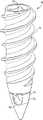
图1示出了本发明的复合材料锚定器的透视图。Figure 1 shows a perspective view of a composite anchor of the present invention.
图2示出了图1的复合材料锚定器的近端部分的透视图。FIG. 2 shows a perspective view of a proximal portion of the composite anchor of FIG. 1 .
图3示出了图2的近端部分的横截面视图。FIG. 3 shows a cross-sectional view of the proximal portion of FIG. 2 .
图4示出了图1的复合材料锚定器的远端部分的透视图。FIG. 4 shows a perspective view of the distal portion of the composite anchor of FIG. 1 .
图5示出了图1的复合材料锚定器的横截面视图。FIG. 5 shows a cross-sectional view of the composite anchor of FIG. 1 .
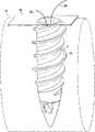
图6A-6C示出了通过使用图1的复合材料锚定器的修复方法。6A-6C illustrate a method of repair by using the composite anchor of FIG. 1 .
具体实施方式Detailed ways
优选实施例的下述描述本质上仅为示例性的,并且决不旨在限制本发明、其应用或使用。The following description of preferred embodiments is merely exemplary in nature and is in no way intended to limit the invention, its application or uses.
图1-5示出了本公开的复合材料锚定器10。锚定器10包括近端部分11和联接到近端部分11的远端部分12。近端部分11包括管道11a、配置成安置远端部分12的内表面11b以及用来将锚定器10插入到骨中的递送装置(未示出),其将在下文作进一步描述,以及包括螺纹11d的外表面11c。远端部分12包括底部部分12a、顶部部分12b以及定位在底部部分12a中的通孔12c。为了允许更容易地将锚定器10插入到骨中,底部部分12a大致为圆锥形,其将在下文作进一步描述。顶部部分12b包括至少两个侧部12d以及定位在该至少两个侧部12d之间的中间部分12e。侧部12d是梯形的并且中间部分12e大致是圆形的。如图5所示,侧部12d的形状顺应内表面11b的形状以便允许侧部12d接合内表面11b并且从而当远端部分12放置在近端部分11的管道11a中时将远端部分12与近端部分11联接。1-5 illustrate a
图6A-6C示出了通过使用本公开的复合材料锚定器来修复的方法。如图6A所示,锚定器10包括至少一条缝线20,其被安置在通孔12c中并且具有延伸通过近端部分11的管道11a的端部20a、20b,使得缝线20被安置在中间部分12e上。如图6B所示,通过使用递送装置40旋进,将锚定器10插入到骨30中。递送装置40延伸了大致近端部分11的长度,从而在锚定器10和递送装置40之间提供足够量的表面接触以允许使用者施加的扭矩比起递送装置40延伸小于大致近端部分11长度所将允许的量更大。在锚定器10上施加更大量的扭矩的能力允许用户将锚定器10插入到骨30中,特别是诸如皮层质骨的硬骨中,而无需在插入锚定器10之前首先在骨30中产生孔,从而在手术中节省了时间。6A-6C illustrate a method of repair by using the composite anchors of the present disclosure. As shown in FIG. 6A , the
在将锚定器10放入到骨30中之后,移去递送装置40并且将软组织50放在骨30上邻近锚定器10布置。然后将缝线端部20a、20b插入穿过软组织50并且打结以将软组织50固定到骨30上,如图6C所示。After
为了本公开的目的,近端部分11包括可吸收材料,诸如可吸收聚合物材料,并且远端部分12包括不可吸收材料,诸如不可吸收聚合物材料或金属材料。可以使用任何的可吸收聚合物材料。可以使用包括了填充物的可吸收材料,该填充物诸如硫酸钙、碳酸钙、磷酸钙、纤维或其它提供增强的强度、骨传导、减低的聚合物pH水平或其它益处的填充物材料。可以使用诸如聚醚醚酮(PEEK)的不可吸收聚合物材料或其它的不可吸收聚合物材料。类似地,金属材料可包括不锈钢、钛或本领域技术人员已知的另外的金属材料。For the purposes of this disclosure, the
相信具有可吸收近端部分11和不可吸收远端部分12的锚定器10将充分减少在近端部分11降解期间软组织50变得松散的可能性。另外,具有复合布置的锚定器提供给外科医生在手术期间使用锚定器类型的更多选择。当前的两件式缝线锚定器整体由金属材料或非金属材料构成。It is believed that an
为了本公开的目的,锚定器10的近端部分11和锚定器10的远端部分12通过近端部分11和远端部分12之间的干涉配合来联接。然而,部件11、12可以通过超声焊接或本领域技术人员已知的另外的联接方法来联接。另外,对于内表面11b、侧部12d、中间部分12e以及底部部分12a来说可能具有不同的形状。此外,除螺纹以外的特征可以呈现在近端部分11的外表面11c上。相反,外表面11c可包括倒钩或允许锚定器10轴向推进到骨30中的其它表面特征。此外,可以布置多于一条缝线到通孔12c中并穿过管道11a。更多地,在将锚定器10插入骨30之前可以在骨30中形成孔。For the purposes of this disclosure, the
由于在不偏离本发明的范围的前提下可对如上关于相应附图描述的示例性实施例进行各种修改,因此本发明旨在将包含在前述说明以及在附图中示出的所有内容应解释为描述性而不是限制性的。因而,本发明的广泛性和范围不应受任何上述示例性实施例限制,而是仅应当根据所附下述权利要求书及其等同物限定。Since various modifications may be made to the exemplary embodiments as described above with respect to the corresponding drawings without departing from the scope of the invention, it is intended that all matter contained in the foregoing description and shown in the accompanying drawings shall be interpreted as descriptive and not restrictive. Thus, the breadth and scope of the present invention should not be limited by any of the above-described exemplary embodiments, but should be defined only in accordance with the following claims appended hereto and their equivalents.
Claims (14)
Applications Claiming Priority (3)
| Application Number | Priority Date | Filing Date | Title |
|---|---|---|---|
| US12251208P | 2008-12-15 | 2008-12-15 | |
| US61/122512 | 2008-12-15 | ||
| PCT/US2009/066966WO2010071742A1 (en) | 2008-12-15 | 2009-12-07 | Composite anchor |
Publications (2)
| Publication Number | Publication Date |
|---|---|
| CN102245112Atrue CN102245112A (en) | 2011-11-16 |
| CN102245112B CN102245112B (en) | 2015-04-01 |
Family
ID=41479267
Family Applications (1)
| Application Number | Title | Priority Date | Filing Date |
|---|---|---|---|
| CN200980150612.6AExpired - Fee RelatedCN102245112B (en) | 2008-12-15 | 2009-12-07 | Composite Anchor |
Country Status (6)
| Country | Link |
|---|---|
| US (2) | US8771315B2 (en) |
| EP (1) | EP2375995A1 (en) |
| JP (1) | JP2012511956A (en) |
| CN (1) | CN102245112B (en) |
| AU (1) | AU2009327446B2 (en) |
| WO (1) | WO2010071742A1 (en) |
Cited By (2)
| Publication number | Priority date | Publication date | Assignee | Title |
|---|---|---|---|---|
| CN106456154A (en)* | 2014-03-06 | 2017-02-22 | 史密夫和内修有限公司 | Two-piece knotless suture anchor |
| CN107809960A (en)* | 2015-06-30 | 2018-03-16 | 史密夫和内修有限公司 | Suture anchor system with thread plug |
Families Citing this family (47)
| Publication number | Priority date | Publication date | Assignee | Title |
|---|---|---|---|---|
| US20240398404A1 (en)* | 2006-07-20 | 2024-12-05 | Lee D. Kaplan | Surgical instruments |
| US8632568B2 (en)* | 2007-09-24 | 2014-01-21 | Stryker Corporation | Suture anchor having a suture engaging structure and inserter arrangement |
| US8197511B2 (en) | 2007-09-24 | 2012-06-12 | Miller M Todd | Suture anchor having a suture engaging structure and inserter arrangement |
| US20230309988A1 (en)* | 2007-10-27 | 2023-10-05 | Parcus Medical, Llc | Suture anchor |
| US20090281581A1 (en) | 2008-05-06 | 2009-11-12 | Berg Jeffery H | Method and device for securing sutures to bones |
| US8771315B2 (en) | 2008-12-15 | 2014-07-08 | Smith & Nephew, Inc. | Composite anchor |
| US8845725B2 (en)* | 2009-04-17 | 2014-09-30 | Lumaca Orthopaedics Pty Ltd | Tenodesis system |
| WO2011056701A1 (en)* | 2009-10-28 | 2011-05-12 | Smith & Nephew, Inc. | Threaded suture anchor |
| FR2960763B1 (en)* | 2010-06-03 | 2013-08-02 | Tornier Sa | SUTURE IMPLANT |
| US8469998B2 (en) | 2010-08-30 | 2013-06-25 | Depuy Mitek, Llc | Knotless suture anchor |
| US8435264B2 (en) | 2010-08-30 | 2013-05-07 | Depuy Mitek, Llc | Knotless suture anchor and driver |
| US8460340B2 (en) | 2010-08-30 | 2013-06-11 | Depuy Mitek, Llc | Knotless suture anchor |
| CN105326533B (en) | 2010-09-24 | 2017-12-08 | 斯博特威尔丁股份有限公司 | Apparatus and method for suture holdfast to be fixed in sclerous tissues |
| JP5989759B2 (en)* | 2011-03-22 | 2016-09-07 | スミス アンド ネフュー インコーポレーテッド | Mooring system and feeding device for use with the mooring system |
| CA2840186A1 (en) | 2011-06-23 | 2012-12-27 | DePuy Synthes Products, LLC | Suture anchor system and method |
| US9107653B2 (en)* | 2011-09-22 | 2015-08-18 | Arthrex, Inc. | Tensionable knotless anchors with splice and methods of tissue repair |
| US20130123809A1 (en) | 2011-11-11 | 2013-05-16 | VentureMD Innovations, LLC | Transosseous attachment instruments |
| US10470756B2 (en) | 2011-11-16 | 2019-11-12 | VentureMD Innovations, LLC | Suture anchor and method |
| US10136883B2 (en) | 2011-11-16 | 2018-11-27 | VentureMD Innovations, LLC | Method of anchoring a suture |
| US10548585B2 (en) | 2011-11-16 | 2020-02-04 | VentureMD Innovations, LLC | Soft tissue attachment |
| US10675014B2 (en) | 2011-11-16 | 2020-06-09 | Crossroads Extremity Systems, Llc | Knotless soft tissue attachment |
| US8858596B2 (en) | 2012-03-20 | 2014-10-14 | Stryker Corporation | Suture anchor having a suture engaging structure |
| US12390258B2 (en) | 2012-07-18 | 2025-08-19 | Jmea Corporation | Methods and apparatus for implanting prostheses |
| US9198704B2 (en) | 2012-07-18 | 2015-12-01 | Jmea Corporation | Impact and drive system for prosthesis deployment device |
| US9687221B2 (en) | 2013-02-13 | 2017-06-27 | Venture MD Innovations, LLC | Method of anchoring a suture |
| CN105188562B (en) | 2013-03-06 | 2019-02-26 | 史密夫和内修有限公司 | Micro Anchor |
| US10980236B2 (en) | 2014-11-04 | 2021-04-20 | Allied Bioscience, Inc. | Broad spectrum antimicrobial coatings comprising combinations of organosilanes |
| US10258401B2 (en) | 2015-07-17 | 2019-04-16 | Kator, Llc | Transosseous guide |
| US10820918B2 (en) | 2015-07-17 | 2020-11-03 | Crossroads Extremity Systems, Llc | Transosseous guide and method |
| US9962174B2 (en) | 2015-07-17 | 2018-05-08 | Kator, Llc | Transosseous method |
| US10226243B2 (en) | 2015-08-04 | 2019-03-12 | Kator, Llc | Transosseous suture anchor |
| US12383253B2 (en) | 2015-08-04 | 2025-08-12 | Crossroads Extremity Systems, Llc | Suture anchor |
| US10265060B2 (en) | 2015-08-20 | 2019-04-23 | Arthrex, Inc. | Tensionable constructs with multi-limb locking mechanism through single splice and methods of tissue repair |
| US10335136B2 (en) | 2015-08-20 | 2019-07-02 | Arthrex, Inc. | Tensionable constructs with multi-limb locking mechanism through single splice and methods of tissue repair |
| US10368855B2 (en) | 2015-10-20 | 2019-08-06 | Arthrex, Inc. | Surgical constructs for tissue repair |
| US10061399B2 (en) | 2016-07-15 | 2018-08-28 | Apple Inc. | Capacitive gap sensor ring for an input device |
| US10893933B2 (en) | 2017-02-24 | 2021-01-19 | James Jastifer | Tissue anchors, kits, and associated methods |
| US10383618B2 (en) | 2017-03-13 | 2019-08-20 | Medos International Sarl | Methods and devices for knotless suture anchoring |
| US10463357B2 (en) | 2017-03-13 | 2019-11-05 | Medos International Sarl | Methods and devices for knotless suture anchoring |
| US10758224B2 (en) | 2017-03-27 | 2020-09-01 | Trimed, Incorporated | System and method controlling a relationship between first and second bodies on a person |
| US10639026B2 (en) | 2017-07-27 | 2020-05-05 | Medos International Sarl | Knotless suture anchoring using two awl shafts |
| WO2019123116A1 (en)* | 2017-12-20 | 2019-06-27 | Peach Dian Samuel | A medical anchor |
| USD921479S1 (en)* | 2018-11-27 | 2021-06-08 | International Life Sciences LLC | Eyelet interference screw |
| USD914213S1 (en)* | 2019-10-07 | 2021-03-23 | Maruho Medical, Inc. | Suture anchor |
| USD914212S1 (en)* | 2019-10-07 | 2021-03-23 | Maruho Medical, Inc. | Suture anchor |
| USD985421S1 (en)* | 2021-05-07 | 2023-05-09 | Classic Home & Garden, LLC | Plug |
| US11350926B1 (en)* | 2021-12-16 | 2022-06-07 | Christopher Ninh | Continuous loop suture assembly and related surgical techniques |
Citations (4)
| Publication number | Priority date | Publication date | Assignee | Title |
|---|---|---|---|---|
| WO2002021997A2 (en)* | 2000-09-12 | 2002-03-21 | Axya Medical, Inc. | Apparatus and method for securing suture to bone |
| WO2006099109A2 (en)* | 2005-03-10 | 2006-09-21 | Tyco Healthcare Group Lp | Suture anchors |
| WO2007078281A2 (en)* | 2005-12-22 | 2007-07-12 | West Hugh S Jr | Bone anchors for use in attaching soft tissue to bone |
| EP2085033A1 (en)* | 2008-01-30 | 2009-08-05 | Arthrex Inc. | Pointed tip implant and interference device for fixing suture and tissue to bone without predrilling |
Family Cites Families (46)
| Publication number | Priority date | Publication date | Assignee | Title |
|---|---|---|---|---|
| US4537185A (en)* | 1983-06-10 | 1985-08-27 | Denis P. Stednitz | Cannulated fixation screw |
| US4870957A (en)* | 1988-12-27 | 1989-10-03 | Marlowe Goble E | Ligament anchor system |
| US5100405A (en) | 1990-09-07 | 1992-03-31 | Mclaren Alexander C | Locking cap for medical implants |
| CA2062012C (en)* | 1991-03-05 | 2003-04-29 | Randall D. Ross | Bioabsorbable interference bone fixation screw |
| US5383905A (en)* | 1992-10-09 | 1995-01-24 | United States Surgical Corporation | Suture loop locking device |
| US5505735A (en)* | 1993-06-10 | 1996-04-09 | Mitek Surgical Products, Inc. | Surgical anchor and method for using the same |
| US5370662A (en)* | 1993-06-23 | 1994-12-06 | Kevin R. Stone | Suture anchor assembly |
| US5584835A (en)* | 1993-10-18 | 1996-12-17 | Greenfield; Jon B. | Soft tissue to bone fixation device and method |
| US5417712A (en)* | 1994-02-17 | 1995-05-23 | Mitek Surgical Products, Inc. | Bone anchor |
| US5957953A (en) | 1996-02-16 | 1999-09-28 | Smith & Nephew, Inc. | Expandable suture anchor |
| US5733307A (en)* | 1996-09-17 | 1998-03-31 | Amei Technologies, Inc. | Bone anchor having a suture trough |
| US5948001A (en)* | 1996-10-03 | 1999-09-07 | United States Surgical Corporation | System for suture anchor placement |
| CA2217406C (en)* | 1996-10-04 | 2006-05-30 | United States Surgical Corporation | Suture anchor installation system with disposable loading unit |
| US6436124B1 (en)* | 1996-12-19 | 2002-08-20 | Bionx Implants Oy | Suture anchor |
| US5935129A (en)* | 1997-03-07 | 1999-08-10 | Innovasive Devices, Inc. | Methods and apparatus for anchoring objects to bone |
| JP2000166937A (en) | 1998-11-30 | 2000-06-20 | Takiron Co Ltd | In-vivo decomposition absorptive screw |
| JP4336023B2 (en) | 1999-05-12 | 2009-09-30 | 浩平 窪田 | Implant screw |
| US6517542B1 (en)* | 1999-08-04 | 2003-02-11 | The Cleveland Clinic Foundation | Bone anchoring system |
| US6923824B2 (en)* | 2000-09-12 | 2005-08-02 | Axya Medical, Inc. | Apparatus and method for securing suture to bone |
| ES2378608T3 (en) | 2000-12-22 | 2012-04-16 | Tyco Healthcare Group Lp | Suture screw |
| US6916321B2 (en)* | 2001-09-28 | 2005-07-12 | Ethicon, Inc. | Self-tapping resorbable two-piece bone screw |
| US7517357B2 (en)* | 2003-01-09 | 2009-04-14 | Linvatec Biomaterials | Knotless suture anchor |
| US7582107B2 (en) | 2003-02-03 | 2009-09-01 | Integra Lifesciences Corporation | Compression screw apparatuses, systems and methods |
| US8016865B2 (en) | 2003-09-29 | 2011-09-13 | Depuy Mitek, Inc. | Method of performing anterior cruciate ligament reconstruction using biodegradable interference screw |
| US8579940B2 (en) | 2004-04-06 | 2013-11-12 | Arthrex, Inc. | Suture anchor with apertures at tip |
| US7938847B2 (en) | 2006-01-04 | 2011-05-10 | Tornier, Inc. | Ring cinch assembly to attach bone to tissue |
| US7976565B1 (en)* | 2004-12-07 | 2011-07-12 | Biomet Sports Medicine, Llc | Expanding suture anchor having an actuator pin |
| US20060149258A1 (en) | 2004-12-14 | 2006-07-06 | Sousa Joaquim P G | Surgical tool and method for fixation of ligaments |
| US20080208253A1 (en)* | 2006-05-18 | 2008-08-28 | Dreyfuss Peter J | Self-punching swivel anchor and method for knotless fixation of tissue |
| US20070161985A1 (en) | 2005-12-05 | 2007-07-12 | Kentomia, Llc . | Screws configured to engage bones, and methods of attaching implants to skeletal regions |
| JP2008029746A (en) | 2006-07-31 | 2008-02-14 | Takiron Co Ltd | Interference screw for fixing tendon or ligament, and fixation set for tendon or ligament |
| US20070219558A1 (en)* | 2006-03-15 | 2007-09-20 | Allen Deutsch | Method and apparatus for arthroscopic surgery using suture anchors |
| US20070219557A1 (en)* | 2006-03-17 | 2007-09-20 | Bourque Bernard J | Soft tissue fixation |
| US20080009904A1 (en)* | 2006-03-17 | 2008-01-10 | Bourque Barnard J | Soft Tissue Fixation |
| US7828820B2 (en)* | 2006-03-21 | 2010-11-09 | Biomet Sports Medicine, Llc | Method and apparatuses for securing suture |
| US7862573B2 (en)* | 2006-04-21 | 2011-01-04 | Darois Roger E | Method and apparatus for surgical fastening |
| US8821542B2 (en)* | 2006-10-31 | 2014-09-02 | Depuy Mitek, Llc | Suture management system |
| DE102006062401A1 (en)* | 2006-12-21 | 2008-06-26 | Karl Storz Gmbh & Co. Kg | Device for introducing an anchor element into a bone |
| US8758406B2 (en)* | 2007-03-05 | 2014-06-24 | Tomier, Inc. | Tack anchor systems, bone anchor systems, and methods of use |
| AU2008316604B2 (en) | 2007-10-25 | 2014-11-06 | Smith & Nephew, Inc. | Anchor assembly |
| WO2009076526A1 (en)* | 2007-12-13 | 2009-06-18 | Smith & Nephew, Inc. | Anchoring system |
| US8974494B2 (en) | 2008-07-17 | 2015-03-10 | Smith & Nephew, Inc. | Surgical devices |
| CN102098968B (en)* | 2008-07-17 | 2015-07-22 | 史密夫和内修有限公司 | Anchor |
| CN103705280B (en) | 2008-11-26 | 2017-11-14 | 史密夫和内修有限公司 | Tissue repair device |
| US8771315B2 (en) | 2008-12-15 | 2014-07-08 | Smith & Nephew, Inc. | Composite anchor |
| US9089377B2 (en) | 2009-02-23 | 2015-07-28 | Orthopediatrics Corp. | Bone screw |
- 2009
- 2009-12-07USUS12/632,220patent/US8771315B2/enactiveActive
- 2009-12-07WOPCT/US2009/066966patent/WO2010071742A1/enactiveApplication Filing
- 2009-12-07JPJP2011540802Apatent/JP2012511956A/enactivePending
- 2009-12-07AUAU2009327446Apatent/AU2009327446B2/ennot_activeCeased
- 2009-12-07EPEP09771445Apatent/EP2375995A1/ennot_activeWithdrawn
- 2009-12-07CNCN200980150612.6Apatent/CN102245112B/ennot_activeExpired - Fee Related
- 2014
- 2014-05-12USUS14/275,399patent/US9386977B2/enactiveActive
Patent Citations (4)
| Publication number | Priority date | Publication date | Assignee | Title |
|---|---|---|---|---|
| WO2002021997A2 (en)* | 2000-09-12 | 2002-03-21 | Axya Medical, Inc. | Apparatus and method for securing suture to bone |
| WO2006099109A2 (en)* | 2005-03-10 | 2006-09-21 | Tyco Healthcare Group Lp | Suture anchors |
| WO2007078281A2 (en)* | 2005-12-22 | 2007-07-12 | West Hugh S Jr | Bone anchors for use in attaching soft tissue to bone |
| EP2085033A1 (en)* | 2008-01-30 | 2009-08-05 | Arthrex Inc. | Pointed tip implant and interference device for fixing suture and tissue to bone without predrilling |
Cited By (3)
| Publication number | Priority date | Publication date | Assignee | Title |
|---|---|---|---|---|
| CN106456154A (en)* | 2014-03-06 | 2017-02-22 | 史密夫和内修有限公司 | Two-piece knotless suture anchor |
| CN106456154B (en)* | 2014-03-06 | 2021-01-05 | 史密夫和内修有限公司 | Two-part knotless suture anchor |
| CN107809960A (en)* | 2015-06-30 | 2018-03-16 | 史密夫和内修有限公司 | Suture anchor system with thread plug |
Also Published As
| Publication number | Publication date |
|---|---|
| US9386977B2 (en) | 2016-07-12 |
| JP2012511956A (en) | 2012-05-31 |
| AU2009327446B2 (en) | 2015-10-15 |
| AU2009327446A1 (en) | 2011-07-07 |
| US20100152773A1 (en) | 2010-06-17 |
| WO2010071742A1 (en) | 2010-06-24 |
| US8771315B2 (en) | 2014-07-08 |
| US20140343605A1 (en) | 2014-11-20 |
| EP2375995A1 (en) | 2011-10-19 |
| CN102245112B (en) | 2015-04-01 |
Similar Documents
| Publication | Publication Date | Title |
|---|---|---|
| CN102245112B (en) | Composite Anchor | |
| CN103826544B (en) | Anchor system and delivery device for use therewith | |
| JP5571076B2 (en) | anchor | |
| US9687224B2 (en) | Anchor assembly | |
| US20200155143A1 (en) | Threaded suture anchor | |
| US7686838B2 (en) | External bullet anchor apparatus and method for use in surgical repair of ligament or tendon | |
| JP5899124B2 (en) | Compound tightening screw and device | |
| US8454654B2 (en) | Anchoring system | |
| US20090018561A1 (en) | Medical device for repair of tissue and method for implantation and fixation | |
| US9492157B2 (en) | Bone anchor apparatus and method | |
| JP2018538026A (en) | Suture anchor assembly with sliding fit tip | |
| US12042139B2 (en) | Knotless suture anchors |
Legal Events
| Date | Code | Title | Description |
|---|---|---|---|
| C06 | Publication | ||
| PB01 | Publication | ||
| C10 | Entry into substantive examination | ||
| SE01 | Entry into force of request for substantive examination | ||
| C14 | Grant of patent or utility model | ||
| GR01 | Patent grant | ||
| CF01 | Termination of patent right due to non-payment of annual fee | Granted publication date:20150401 Termination date:20181207 | |
| CF01 | Termination of patent right due to non-payment of annual fee |